US6162169A - Transducer arrangement for partially or fully implantable hearing aids - Google Patents
Transducer arrangement for partially or fully implantable hearing aidsDownload PDFInfo
- Publication number
- US6162169A US6162169AUS09/275,872US27587299AUS6162169AUS 6162169 AUS6162169 AUS 6162169AUS 27587299 AUS27587299 AUS 27587299AUS 6162169 AUS6162169 AUS 6162169A
- Authority
- US
- United States
- Prior art keywords
- housing
- transducer
- vibratory
- component
- coupling element
- Prior art date
- Legal status (The legal status is an assumption and is not a legal conclusion. Google has not performed a legal analysis and makes no representation as to the accuracy of the status listed.)
- Expired - Lifetime
Links
Images

Classifications
- H—ELECTRICITY
- H04—ELECTRIC COMMUNICATION TECHNIQUE
- H04R—LOUDSPEAKERS, MICROPHONES, GRAMOPHONE PICK-UPS OR LIKE ACOUSTIC ELECTROMECHANICAL TRANSDUCERS; DEAF-AID SETS; PUBLIC ADDRESS SYSTEMS
- H04R25/00—Deaf-aid sets, i.e. electro-acoustic or electro-mechanical hearing aids; Electric tinnitus maskers providing an auditory perception
- H04R25/60—Mounting or interconnection of hearing aid parts, e.g. inside tips, housings or to ossicles
- H04R25/604—Mounting or interconnection of hearing aid parts, e.g. inside tips, housings or to ossicles of acoustic or vibrational transducers
- H04R25/606—Mounting or interconnection of hearing aid parts, e.g. inside tips, housings or to ossicles of acoustic or vibrational transducers acting directly on the eardrum, the ossicles or the skull, e.g. mastoid, tooth, maxillary or mandibular bone, or mechanically stimulating the cochlea, e.g. at the oval window
- H—ELECTRICITY
- H04—ELECTRIC COMMUNICATION TECHNIQUE
- H04R—LOUDSPEAKERS, MICROPHONES, GRAMOPHONE PICK-UPS OR LIKE ACOUSTIC ELECTROMECHANICAL TRANSDUCERS; DEAF-AID SETS; PUBLIC ADDRESS SYSTEMS
- H04R2225/00—Details of deaf aids covered by H04R25/00, not provided for in any of its subgroups
- H04R2225/67—Implantable hearing aids or parts thereof not covered by H04R25/606
- H—ELECTRICITY
- H04—ELECTRIC COMMUNICATION TECHNIQUE
- H04R—LOUDSPEAKERS, MICROPHONES, GRAMOPHONE PICK-UPS OR LIKE ACOUSTIC ELECTROMECHANICAL TRANSDUCERS; DEAF-AID SETS; PUBLIC ADDRESS SYSTEMS
- H04R25/00—Deaf-aid sets, i.e. electro-acoustic or electro-mechanical hearing aids; Electric tinnitus maskers providing an auditory perception
- H04R25/55—Deaf-aid sets, i.e. electro-acoustic or electro-mechanical hearing aids; Electric tinnitus maskers providing an auditory perception using an external connection, either wireless or wired
- H04R25/558—Remote control, e.g. of amplification, frequency
Definitions
- This inventionrelates to the field of transducers for partially or fully implantable hearing aids for direct mechanical excitation of the middle or inner ear. More specifically, this invention relates to such transducers including a housing which can be fixed at the implantation site with respect to the skull and a coupling element which can move with respect to the housing, the housing accommodating an electromechanical transducer by which the coupling element can transmit vibrations from the electromechanical transducer to the middle ear ossicle or directly to the inner ear.
- a transducer arrangement of this general typeis known from U.S. Pat. No. 5,277,694.
- one wall of a housingbe made as a vibrating membrane with an electromechanically active heteromorphic composite element with a piezoelectric ceramic disk attached to the side of the membrane inside the housing.
- a hearing aid transducer built in this mannercan be implanted without difficulty and generally good results have been achieved.
- the coupling element driven by the piezoelectric ceramic diskdoes not create sufficient deflections to provide adequate loudness level for patients with medium and more serious hearing loss. This insufficient deflection has been attributed, in part, to be caused by the low electrical voltages required for such implants.
- U.S. Pat. No. 5,624,376discloses a transducer for partially or fully implantable hearing aids based on the electromagnetic principle in which a permanent magnet, together with two assigned pole pieces, is loosely suspended in a cylindrical housing.
- An induction coilwhich interacts with the permanent magnet is positioned in a cylindrical air gap bounded by the pole pieces and is permanently joined to one housing wall.
- a grounded portionconsisting of the permanent magnet and the pole pieces is vibrated.
- This grounded portionis mechanically coupled to the housing which is designed for attachment to a vibratory structure of the ear.
- the grounded portionis vibrated, the resulting vibration of the housing stimulates the vibratory structure of the ear.
- the primary object of the present inventionis to devise a hearing aid transducer which is mechanically coupled to a middle ear ossicle or directly to the inner ear for transmission of vibration.
- a second object of the present inventionis to devise a hearing aid transducer of the initially mentioned type which can generate even relatively low frequency vibrations with sufficient amplitude while using relatively little energy.
- Yet another object of the present inventionis to devise a hearing aid transducer which accomplishes the above objectives and may be surgically implanted without difficulty.
- an electromechanical hearing aid transducerincluding an electromagnet arrangement with an electromagnetic component which is fixed relative to the housing and a vibratory component which is connected to the coupling element such that the vibrations of the vibratory component are transferred to the coupling element.
- the present inventionhas advantages over the prior art hearing aid transducers in that the present transducer may be implanted easily without the problems associated with the piezoelectric transducer disclosed in U.S. Pat. No. 5,277,694 and be implanted with respect to a bony portion of the skull.
- the frequency response of the present transduceris improved especially at low frequencies of the hearing range so that adequate hearing loudness is achieved despite the low operating electrical voltages required in such implants.
- one wall of the housingmay be made to vibrate and may be formed as a vibratory membrane with a vibratory component attached to the side of the membrane inside the housing and the coupling element connected to the side of the membrane outside the housing.
- the housingis preferably made to be hermetically sealed and biocompatible.
- the preferred embodimentis advantageously made cylindrical and has one peripheral wall and two circular end walls which run essentially parallel to one another. One of the two circular end walls forms the vibratory membrane while the other circular end wall can be integrally joined to the peripheral wall of the housing.
- both the vibratory component and also the coupling elementare attached essentially at the center of the vibratory membrane.
- a vibratory componentwhich may be a permanent magnet, is connected to the side of the membrane inside the housing.
- An electromagnetic elementsuch as a coil is permanently attached within the housing and is operable to cause vibration of the permanent magnet.
- the permanent magnetmay be made as a magnetic pin and the electromagnetic component may be made as a ring coil with a center opening where the vibratory component such as the magnetic pin may be positioned. This yields a transducer with an especially small mass which is moved to create the vibration which promptly and accurately reflect changes in the electrical signal applied to the electromagnetic element.
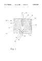
- FIG. 1shows a sectional view of a transducer in accordance with the preferred embodiment of the present invention.
- FIG. 2shows a sectional view of a human ear with an implanted hearing aid including a transducer in accordance with the present invention as illustrated in FIG. 1.
- FIG. 1shows an implantable transducer arrangement for a hearing aid for direct mechanical excitation of the middle or inner ear including an electromechanical transducer 10 in accordance with the preferred embodiment of the present invention.
- a detectorsuch as a microphone 58 (as shown in FIG. 2), may be provided and is preferably implanted to receive the sound.
- the transducer 10is equipped with a hermetically sealed, biocompatible cylindrical housing 14.
- the housing 14is preferably made of metal, for example, titanium, niobium, tantalum, iridium or their alloys and is filled with an inert gas 16.
- the housing 14has one peripheral wall 11 and two circular end walls 12 and 18 which are substantially perpendicular to the peripheral wall 11.
- the end wall 12may be integrally joined to the peripheral wall 11 of the housing.
- the end wall 18 of the housing 14is made as a thin vibratory membrane 18 with a coupling element 20 fixedly attached to the side of the vibratory membrane 18 outside the housing 14.
- the coupling element 20is preferably welded or cemented to the center of the vibratory membrane 18 and provides mechanical vibrational coupling to the middle ear ossicle or directly to the inner ear.
- the electromagnet arrangementincludes an electromagnetic component 32 and a vibratory component 30.
- the vibratory component 30is provided at the center of the vibratory membrane 18 on the side of the vibratory membrane 18 inside the housing 14.
- the vibratory component 30may be a pin or rod shaped permanent magnet and may be attached to the vibratory membrane 18 by an adhesive or other attaching means.
- the electromagnetic component 32is also provided within the housing 14 and is permanently fixed, for example, by cementing it to the housing 14.
- the electromagnetic component 32may be a coil or a ring coil with a central opening so that the vibratory component 30 may be positioned and displaced within the central opening of the electromagnetic component 32 as illustrated in FIG. 1.
- an electrically insulating, hermetic penetration 26is provided on the end wall 12 so that the terminals 36, which are electrically connected to the electromagnetic component 32 by wires 34, may be routed out of the housing 14.
- Excitation of the electromagnetic component 32 by application of an AC voltage to the terminals 36causes a displacement of the vibratory component 30 relative to the housing-mounted electromagnetic component 32 thereby causing deflection of the vibratory membrane 18.
- the electromagnetic component 32may be a ring coil and the vibratory component 30 may be a permanent pin magnet.
- the deflection of the vibratory membrane 18is transmitted via the coupling element 20 to the middle-ear ossicle or directly to the inner ear.
- the coupling element 20may be made as a connecting rod and can be connected to the ossicular chain, for example, by a thin wire or hollow wire clip or a clip of carbon fiber-reinforced composite. Suitable arrangements of this type are described in commonly owned, co-pending U.S. Pat. application Ser. No. 09/042,805 which is hereby incorporated by reference.
- FIG. 2shows an implanted hearing aid 51 which is equipped with a transducer 10 of the above described type as implanted in a human ear 100.
- the hearing aid 51includes a battery unit 53, a charging reception coil 54, and an electronic module 55. These components are accommodated in a hermetically sealed housing 56 which can be implanted in the mastoid region 57.
- the transducer 10 and a microphone 58are connected via wires 59 and 60 to the electronic module 55.
- the coupling element 20(illustrated penetrating through an opening on the incus) is coupled to the ossicular chain 62.
- the portable charging unit 63includes a charging transmission coil 64 which can be inductively coupled to the charging reception coil 54 for transcutaneous charging of the battery unit 53.
- a remote control unit 65may also be provided.
- a hearing aid of this general typeis exemplified in U.S. Pat. No. 5,277,694 and therefore, need not be discussed in further detail here.
Landscapes
- Health & Medical Sciences (AREA)
- General Health & Medical Sciences (AREA)
- Otolaryngology (AREA)
- Neurosurgery (AREA)
- Physics & Mathematics (AREA)
- Engineering & Computer Science (AREA)
- Acoustics & Sound (AREA)
- Signal Processing (AREA)
- Prostheses (AREA)
- Electrotherapy Devices (AREA)
Abstract
Description
Claims (10)
Applications Claiming Priority (2)
| Application Number | Priority Date | Filing Date | Title |
|---|---|---|---|
| DE19840212 | 1998-09-03 | ||
| DE19840212ADE19840212C2 (en) | 1998-09-03 | 1998-09-03 | Transducer arrangement for partially or fully implantable hearing aids |
Publications (1)
| Publication Number | Publication Date |
|---|---|
| US6162169Atrue US6162169A (en) | 2000-12-19 |
Family
ID=7879710
Family Applications (1)
| Application Number | Title | Priority Date | Filing Date |
|---|---|---|---|
| US09/275,872Expired - LifetimeUS6162169A (en) | 1998-09-03 | 1999-03-25 | Transducer arrangement for partially or fully implantable hearing aids |
Country Status (6)
| Country | Link |
|---|---|
| US (1) | US6162169A (en) |
| EP (1) | EP0984663B1 (en) |
| AU (1) | AU760815B2 (en) |
| CA (1) | CA2274211C (en) |
| DE (2) | DE19840212C2 (en) |
| DK (1) | DK0984663T3 (en) |
Cited By (20)
| Publication number | Priority date | Publication date | Assignee | Title |
|---|---|---|---|---|
| US20020138115A1 (en)* | 2001-03-26 | 2002-09-26 | Cochlear Limited | Totally implantable hearing system |
| US6537200B2 (en) | 2000-03-28 | 2003-03-25 | Cochlear Limited | Partially or fully implantable hearing system |
| US6554762B2 (en) | 2000-08-25 | 2003-04-29 | Cochlear Limited | Implantable hearing system with means for measuring its coupling quality |
| US6592512B2 (en) | 2000-08-11 | 2003-07-15 | Phonak Ag | At least partially implantable system for rehabilitation of a hearing disorder |
| US6689045B2 (en) | 1998-09-24 | 2004-02-10 | St. Croix Medical, Inc. | Method and apparatus for improving signal quality in implantable hearing systems |
| US6697674B2 (en) | 2000-04-13 | 2004-02-24 | Cochlear Limited | At least partially implantable system for rehabilitation of a hearing disorder |
| US20040039244A1 (en)* | 2001-09-06 | 2004-02-26 | Kai Kroll | Method for creating a coupling between a device and an ear structure in an implantable hearing assistance device |
| US20040097785A1 (en)* | 2002-11-20 | 2004-05-20 | Phonak Ag | Implantable transducer for hearing aids and process for tuning the frequency response of one such transducer |
| US20040147804A1 (en)* | 2003-01-27 | 2004-07-29 | Schneider Robert Edwin | Implantable hearing aid transducer with advanceable actuator to facilitate coupling with the auditory system |
| WO2006058368A1 (en)* | 2004-11-30 | 2006-06-08 | Cochlear Acoustics Ltd | Implantable actuator for hearing aid applications |
| US20070014423A1 (en)* | 2005-07-18 | 2007-01-18 | Lotus Technology, Inc. | Behind-the-ear auditory device |
| US7226406B2 (en) | 2000-09-25 | 2007-06-05 | Cochlear Limited | At least partially implantable hearing system |
| US20080051623A1 (en)* | 2003-01-27 | 2008-02-28 | Schneider Robert E | Simplified implantable hearing aid transducer apparatus |
| US20080205679A1 (en)* | 2005-07-18 | 2008-08-28 | Darbut Alexander L | In-Ear Auditory Device and Methods of Using Same |
| WO2011113468A1 (en)* | 2010-03-15 | 2011-09-22 | Advanced Bionics Ag | Hearing aid and method of implanting a hearing aid |
| WO2012045852A2 (en) | 2010-10-08 | 2012-04-12 | 3Win N.V. | Implantable actuator for hearing applications |
| US9179226B2 (en) | 2008-02-07 | 2015-11-03 | Advanced Bionics Ag | Partially implantable hearing device |
| US9729981B2 (en) | 2011-05-12 | 2017-08-08 | Cochlear Limited | Identifying hearing prosthesis actuator resonance peak(s) |
| US10321247B2 (en) | 2015-11-27 | 2019-06-11 | Cochlear Limited | External component with inductance and mechanical vibratory functionality |
| US11245991B2 (en) | 2013-03-15 | 2022-02-08 | Cochlear Limited | Determining impedance-related phenomena in vibrating actuator and identifying device system characteristics based thereon |
Families Citing this family (5)
| Publication number | Priority date | Publication date | Assignee | Title |
|---|---|---|---|---|
| DE19858399C2 (en)* | 1998-12-17 | 2003-02-20 | Phonak Ag Staefa | Electroacoustic transducer for hearing aids for airborne sound radiation in the external auditory canal |
| DE19859171C2 (en)* | 1998-12-21 | 2000-11-09 | Implex Hear Tech Ag | Implantable hearing aid with tinnitus masker or noiser |
| DE19931788C1 (en) | 1999-07-08 | 2000-11-30 | Implex Hear Tech Ag | Implanted mechanical coupling device for auditory ossicle chain in hearing aid system has associated settling device for movement of coupling device between open and closed positions |
| DE19935029C2 (en) | 1999-07-26 | 2003-02-13 | Phonak Ag Staefa | Implantable arrangement for mechanically coupling a driver part to a coupling point |
| DE10031832C2 (en) | 2000-06-30 | 2003-04-30 | Cochlear Ltd | Hearing aid for the rehabilitation of a hearing disorder |
Citations (8)
| Publication number | Priority date | Publication date | Assignee | Title |
|---|---|---|---|---|
| US3870832A (en)* | 1972-07-18 | 1975-03-11 | John M Fredrickson | Implantable electromagnetic hearing aid |
| DE4221866A1 (en)* | 1992-07-03 | 1994-01-05 | Guenter Hortmann | Hearing aid exciting inner ear with implanted electromechanical converter - converts electrical signals supplied to it into transmitted mechanical vibrations and converter is designed as intra-cochlear liquid sound transmitter |
| US5277694A (en)* | 1991-02-13 | 1994-01-11 | Implex Gmbh | Electromechanical transducer for implantable hearing aids |
| US5282858A (en)* | 1991-06-17 | 1994-02-01 | American Cyanamid Company | Hermetically sealed implantable transducer |
| US5554096A (en)* | 1993-07-01 | 1996-09-10 | Symphonix | Implantable electromagnetic hearing transducer |
| US5558618A (en)* | 1995-01-23 | 1996-09-24 | Maniglia; Anthony J. | Semi-implantable middle ear hearing device |
| US5624376A (en)* | 1993-07-01 | 1997-04-29 | Symphonix Devices, Inc. | Implantable and external hearing systems having a floating mass transducer |
| US5772575A (en)* | 1995-09-22 | 1998-06-30 | S. George Lesinski | Implantable hearing aid |
Family Cites Families (3)
| Publication number | Priority date | Publication date | Assignee | Title |
|---|---|---|---|---|
| FR712903A (en)* | 1931-02-17 | 1931-10-26 | Acoustic horn for hard of hearing people | |
| US3882285A (en)* | 1973-10-09 | 1975-05-06 | Vicon Instr Company | Implantable hearing aid and method of improving hearing |
| US4628907A (en)* | 1984-03-22 | 1986-12-16 | Epley John M | Direct contact hearing aid apparatus |
- 1998
- 1998-09-03DEDE19840212Apatent/DE19840212C2/ennot_activeExpired - Fee Related
- 1998-11-12DEDE59814473Tpatent/DE59814473D1/ennot_activeExpired - Lifetime
- 1998-11-12DKDK98121495.0Tpatent/DK0984663T3/enactive
- 1998-11-12EPEP98121495Apatent/EP0984663B1/ennot_activeExpired - Lifetime
- 1999
- 1999-03-25USUS09/275,872patent/US6162169A/ennot_activeExpired - Lifetime
- 1999-03-30AUAU22508/99Apatent/AU760815B2/ennot_activeCeased
- 1999-06-11CACA002274211Apatent/CA2274211C/ennot_activeExpired - Fee Related
Patent Citations (8)
| Publication number | Priority date | Publication date | Assignee | Title |
|---|---|---|---|---|
| US3870832A (en)* | 1972-07-18 | 1975-03-11 | John M Fredrickson | Implantable electromagnetic hearing aid |
| US5277694A (en)* | 1991-02-13 | 1994-01-11 | Implex Gmbh | Electromechanical transducer for implantable hearing aids |
| US5282858A (en)* | 1991-06-17 | 1994-02-01 | American Cyanamid Company | Hermetically sealed implantable transducer |
| DE4221866A1 (en)* | 1992-07-03 | 1994-01-05 | Guenter Hortmann | Hearing aid exciting inner ear with implanted electromechanical converter - converts electrical signals supplied to it into transmitted mechanical vibrations and converter is designed as intra-cochlear liquid sound transmitter |
| US5554096A (en)* | 1993-07-01 | 1996-09-10 | Symphonix | Implantable electromagnetic hearing transducer |
| US5624376A (en)* | 1993-07-01 | 1997-04-29 | Symphonix Devices, Inc. | Implantable and external hearing systems having a floating mass transducer |
| US5558618A (en)* | 1995-01-23 | 1996-09-24 | Maniglia; Anthony J. | Semi-implantable middle ear hearing device |
| US5772575A (en)* | 1995-09-22 | 1998-06-30 | S. George Lesinski | Implantable hearing aid |
Cited By (38)
| Publication number | Priority date | Publication date | Assignee | Title |
|---|---|---|---|---|
| US6689045B2 (en) | 1998-09-24 | 2004-02-10 | St. Croix Medical, Inc. | Method and apparatus for improving signal quality in implantable hearing systems |
| US6537200B2 (en) | 2000-03-28 | 2003-03-25 | Cochlear Limited | Partially or fully implantable hearing system |
| US20040172102A1 (en)* | 2000-04-13 | 2004-09-02 | Cochlear Limited | At least partially implantable system for rehabilitation of a hearing disorder |
| US6697674B2 (en) | 2000-04-13 | 2004-02-24 | Cochlear Limited | At least partially implantable system for rehabilitation of a hearing disorder |
| US6592512B2 (en) | 2000-08-11 | 2003-07-15 | Phonak Ag | At least partially implantable system for rehabilitation of a hearing disorder |
| US6554762B2 (en) | 2000-08-25 | 2003-04-29 | Cochlear Limited | Implantable hearing system with means for measuring its coupling quality |
| US8105229B2 (en) | 2000-09-15 | 2012-01-31 | Cochlear Limited | At least partially implantable hearing system |
| US20070249890A1 (en)* | 2000-09-15 | 2007-10-25 | Cochlear Limited | At least partially implantable hearing system |
| US7226406B2 (en) | 2000-09-25 | 2007-06-05 | Cochlear Limited | At least partially implantable hearing system |
| US20020138115A1 (en)* | 2001-03-26 | 2002-09-26 | Cochlear Limited | Totally implantable hearing system |
| US6807445B2 (en) | 2001-03-26 | 2004-10-19 | Cochlear Limited | Totally implantable hearing system |
| US6875166B2 (en) | 2001-09-06 | 2005-04-05 | St. Croix Medical, Inc. | Method for creating a coupling between a device and an ear structure in an implantable hearing assistance device |
| US20040039244A1 (en)* | 2001-09-06 | 2004-02-26 | Kai Kroll | Method for creating a coupling between a device and an ear structure in an implantable hearing assistance device |
| EP1422971A1 (en)* | 2002-11-20 | 2004-05-26 | Phonak Ag | Implantable transducer for hearing systems and method for adjusting the frequency response of such a transducer |
| AU2003204136B2 (en)* | 2002-11-20 | 2008-11-20 | Phonak Ag | Implantable Transducer for Hearing Aids and Process for Tuning the Frequency Response of One Such Transducer |
| US6855104B2 (en) | 2002-11-20 | 2005-02-15 | Phonak Ag | Implantable transducer for hearing aids and process for tuning the frequency response of one such transducer |
| US20040097785A1 (en)* | 2002-11-20 | 2004-05-20 | Phonak Ag | Implantable transducer for hearing aids and process for tuning the frequency response of one such transducer |
| US7278963B2 (en)* | 2003-01-27 | 2007-10-09 | Otologics, Llc | Implantable hearing aid transducer with advanceable actuator to facilitate coupling with the auditory system |
| US20040147804A1 (en)* | 2003-01-27 | 2004-07-29 | Schneider Robert Edwin | Implantable hearing aid transducer with advanceable actuator to facilitate coupling with the auditory system |
| US8366601B2 (en) | 2003-01-27 | 2013-02-05 | Cochlear Limited | Simplified implantable hearing aid transducer apparatus |
| US20080051623A1 (en)* | 2003-01-27 | 2008-02-28 | Schneider Robert E | Simplified implantable hearing aid transducer apparatus |
| US7905824B2 (en) | 2003-01-27 | 2011-03-15 | Otologics, Llc | Implantable hearing aid transducer with advanceable actuator to faciliate coupling with the auditory system |
| US20080249351A1 (en)* | 2003-01-27 | 2008-10-09 | Robert Edwin Schneider | Implantable hearing aid transducer with advanceable actuator to faciliate coupling with the auditory system |
| JP4864901B2 (en)* | 2004-11-30 | 2012-02-01 | アドバンスド・バイオニクス・アクチエンゲゼルシャフト | Implantable actuator for hearing aid |
| US8602964B2 (en) | 2004-11-30 | 2013-12-10 | Cochlear Limited | Implantable actuator for hearing aid applications |
| AU2005312331B2 (en)* | 2004-11-30 | 2010-04-22 | Cochlear Acoustics Ltd | Implantable actuator for hearing aid applications |
| US20080188707A1 (en)* | 2004-11-30 | 2008-08-07 | Hans Bernard | Implantable Actuator For Hearing Aid Applications |
| WO2006058368A1 (en)* | 2004-11-30 | 2006-06-08 | Cochlear Acoustics Ltd | Implantable actuator for hearing aid applications |
| US20070014423A1 (en)* | 2005-07-18 | 2007-01-18 | Lotus Technology, Inc. | Behind-the-ear auditory device |
| US20070127757A2 (en)* | 2005-07-18 | 2007-06-07 | Soundquest, Inc. | Behind-The-Ear-Auditory Device |
| US20080205679A1 (en)* | 2005-07-18 | 2008-08-28 | Darbut Alexander L | In-Ear Auditory Device and Methods of Using Same |
| US9179226B2 (en) | 2008-02-07 | 2015-11-03 | Advanced Bionics Ag | Partially implantable hearing device |
| WO2011113468A1 (en)* | 2010-03-15 | 2011-09-22 | Advanced Bionics Ag | Hearing aid and method of implanting a hearing aid |
| US9215537B2 (en) | 2010-03-15 | 2015-12-15 | Advanced Bionics Ag | Hearing aid and method of implanting a hearing aid |
| WO2012045852A2 (en) | 2010-10-08 | 2012-04-12 | 3Win N.V. | Implantable actuator for hearing applications |
| US9729981B2 (en) | 2011-05-12 | 2017-08-08 | Cochlear Limited | Identifying hearing prosthesis actuator resonance peak(s) |
| US11245991B2 (en) | 2013-03-15 | 2022-02-08 | Cochlear Limited | Determining impedance-related phenomena in vibrating actuator and identifying device system characteristics based thereon |
| US10321247B2 (en) | 2015-11-27 | 2019-06-11 | Cochlear Limited | External component with inductance and mechanical vibratory functionality |
Also Published As
| Publication number | Publication date |
|---|---|
| DE19840212A1 (en) | 2000-03-23 |
| EP0984663A3 (en) | 2006-05-17 |
| EP0984663B1 (en) | 2010-10-27 |
| DK0984663T3 (en) | 2011-02-14 |
| CA2274211C (en) | 2002-07-09 |
| DE59814473D1 (en) | 2010-12-09 |
| DE19840212C2 (en) | 2001-08-02 |
| CA2274211A1 (en) | 2000-03-03 |
| AU760815B2 (en) | 2003-05-22 |
| EP0984663A2 (en) | 2000-03-08 |
| AU2250899A (en) | 2000-03-16 |
Similar Documents
| Publication | Publication Date | Title |
|---|---|---|
| US6162169A (en) | Transducer arrangement for partially or fully implantable hearing aids | |
| US6123660A (en) | Partially or fully implantable hearing aid | |
| US5558618A (en) | Semi-implantable middle ear hearing device | |
| US5456654A (en) | Implantable magnetic hearing aid transducer | |
| US7753838B2 (en) | Implantable transducer with transverse force application | |
| AU2009324613B2 (en) | Skull vibrational unit | |
| US6005955A (en) | Middle ear transducer | |
| US6171229B1 (en) | Ossicular transducer attachment for an implantable hearing device | |
| US5277694A (en) | Electromechanical transducer for implantable hearing aids | |
| US6161046A (en) | Totally implantable cochlear implant for improvement of partial and total sensorineural hearing loss | |
| CA2071240C (en) | Hermetically sealed implantable transducer | |
| AU778293B2 (en) | At least partially implantable hearing system for rehabilitation of a hearing disorder | |
| US6726618B2 (en) | Hearing aid with internal acoustic middle ear transducer | |
| US7524278B2 (en) | Hearing aid system and transducer with hermetically sealed housing | |
| US20170070828A1 (en) | Implantable middle ear transducer having improved frequency response | |
| US7297101B2 (en) | Method and apparatus for minimally invasive placement of sensing and driver assemblies to improve hearing loss | |
| SE533430C2 (en) | Implantable vibrator | |
| AU2012216732B2 (en) | Skull vibrational unit |
Legal Events
| Date | Code | Title | Description |
|---|---|---|---|
| AS | Assignment | Owner name:IMPLEX AKTIENGESELLSCHAFT HEARING TECHNOLOGY, GERM Free format text:ASSIGNMENT OF ASSIGNORS INTEREST;ASSIGNOR:LEYSIEFFER, HANS;REEL/FRAME:010015/0130 Effective date:19990601 | |
| STCF | Information on status: patent grant | Free format text:PATENTED CASE | |
| AS | Assignment | Owner name:PHONAK AG, SWITZERLAND Free format text:GERMAN COPY OF THE COURT OF BANKRUPTCY DOCUMENT, EXECUTED AGUGUST 1, 2001; ENGLISH TRANSLATION OF THE COURT OF BANKRUPTCY DOCUMENT; VERIFICATION OF TRANSLATION OF THE COURT OF BANKRUPTCY DOCUMENT;ASSIGNOR:IMPLEX AG HEARING TECHNOLOGY;REEL/FRAME:012520/0862 Effective date:20011212 | |
| FPAY | Fee payment | Year of fee payment:4 | |
| FEPP | Fee payment procedure | Free format text:PAT HOLDER NO LONGER CLAIMS SMALL ENTITY STATUS, ENTITY STATUS SET TO UNDISCOUNTED (ORIGINAL EVENT CODE: STOL); ENTITY STATUS OF PATENT OWNER: LARGE ENTITY | |
| FEPP | Fee payment procedure | Free format text:PETITION RELATED TO MAINTENANCE FEES FILED (ORIGINAL EVENT CODE: PMFP); ENTITY STATUS OF PATENT OWNER: LARGE ENTITY | |
| FEPP | Fee payment procedure | Free format text:ENTITY STATUS SET TO UNDISCOUNTED (ORIGINAL EVENT CODE: BIG.); ENTITY STATUS OF PATENT OWNER: LARGE ENTITY | |
| FPAY | Fee payment | Year of fee payment:8 | |
| FPAY | Fee payment | Year of fee payment:12 |