US6162123A - Interactive electronic sword game - Google Patents
Interactive electronic sword gameDownload PDFInfo
- Publication number
- US6162123A US6162123AUS08/977,806US97780697AUS6162123AUS 6162123 AUS6162123 AUS 6162123AUS 97780697 AUS97780697 AUS 97780697AUS 6162123 AUS6162123 AUS 6162123A
- Authority
- US
- United States
- Prior art keywords
- sword
- game
- flywheel
- controller
- housing
- Prior art date
- Legal status (The legal status is an assumption and is not a legal conclusion. Google has not performed a legal analysis and makes no representation as to the accuracy of the status listed.)
- Expired - Lifetime
Links
Images


Classifications
- A—HUMAN NECESSITIES
- A63—SPORTS; GAMES; AMUSEMENTS
- A63F—CARD, BOARD, OR ROULETTE GAMES; INDOOR GAMES USING SMALL MOVING PLAYING BODIES; VIDEO GAMES; GAMES NOT OTHERWISE PROVIDED FOR
- A63F13/00—Video games, i.e. games using an electronically generated display having two or more dimensions
- A63F13/20—Input arrangements for video game devices
- A63F13/21—Input arrangements for video game devices characterised by their sensors, purposes or types
- A63F13/211—Input arrangements for video game devices characterised by their sensors, purposes or types using inertial sensors, e.g. accelerometers or gyroscopes
- A—HUMAN NECESSITIES
- A63—SPORTS; GAMES; AMUSEMENTS
- A63F—CARD, BOARD, OR ROULETTE GAMES; INDOOR GAMES USING SMALL MOVING PLAYING BODIES; VIDEO GAMES; GAMES NOT OTHERWISE PROVIDED FOR
- A63F13/00—Video games, i.e. games using an electronically generated display having two or more dimensions
- A63F13/20—Input arrangements for video game devices
- A63F13/21—Input arrangements for video game devices characterised by their sensors, purposes or types
- A63F13/213—Input arrangements for video game devices characterised by their sensors, purposes or types comprising photodetecting means, e.g. cameras, photodiodes or infrared cells
- A—HUMAN NECESSITIES
- A63—SPORTS; GAMES; AMUSEMENTS
- A63F—CARD, BOARD, OR ROULETTE GAMES; INDOOR GAMES USING SMALL MOVING PLAYING BODIES; VIDEO GAMES; GAMES NOT OTHERWISE PROVIDED FOR
- A63F13/00—Video games, i.e. games using an electronically generated display having two or more dimensions
- A63F13/20—Input arrangements for video game devices
- A63F13/24—Constructional details thereof, e.g. game controllers with detachable joystick handles
- A63F13/245—Constructional details thereof, e.g. game controllers with detachable joystick handles specially adapted to a particular type of game, e.g. steering wheels
- A—HUMAN NECESSITIES
- A63—SPORTS; GAMES; AMUSEMENTS
- A63F—CARD, BOARD, OR ROULETTE GAMES; INDOOR GAMES USING SMALL MOVING PLAYING BODIES; VIDEO GAMES; GAMES NOT OTHERWISE PROVIDED FOR
- A63F13/00—Video games, i.e. games using an electronically generated display having two or more dimensions
- A63F13/25—Output arrangements for video game devices
- A63F13/28—Output arrangements for video game devices responding to control signals received from the game device for affecting ambient conditions, e.g. for vibrating players' seats, activating scent dispensers or affecting temperature or light
- A63F13/285—Generating tactile feedback signals via the game input device, e.g. force feedback
- A—HUMAN NECESSITIES
- A63—SPORTS; GAMES; AMUSEMENTS
- A63F—CARD, BOARD, OR ROULETTE GAMES; INDOOR GAMES USING SMALL MOVING PLAYING BODIES; VIDEO GAMES; GAMES NOT OTHERWISE PROVIDED FOR
- A63F13/00—Video games, i.e. games using an electronically generated display having two or more dimensions
- A63F13/40—Processing input control signals of video game devices, e.g. signals generated by the player or derived from the environment
- A63F13/42—Processing input control signals of video game devices, e.g. signals generated by the player or derived from the environment by mapping the input signals into game commands, e.g. mapping the displacement of a stylus on a touch screen to the steering angle of a virtual vehicle
- A63F13/426—Processing input control signals of video game devices, e.g. signals generated by the player or derived from the environment by mapping the input signals into game commands, e.g. mapping the displacement of a stylus on a touch screen to the steering angle of a virtual vehicle involving on-screen location information, e.g. screen coordinates of an area at which the player is aiming with a light gun
- A—HUMAN NECESSITIES
- A63—SPORTS; GAMES; AMUSEMENTS
- A63F—CARD, BOARD, OR ROULETTE GAMES; INDOOR GAMES USING SMALL MOVING PLAYING BODIES; VIDEO GAMES; GAMES NOT OTHERWISE PROVIDED FOR
- A63F13/00—Video games, i.e. games using an electronically generated display having two or more dimensions
- A63F13/40—Processing input control signals of video game devices, e.g. signals generated by the player or derived from the environment
- A63F13/42—Processing input control signals of video game devices, e.g. signals generated by the player or derived from the environment by mapping the input signals into game commands, e.g. mapping the displacement of a stylus on a touch screen to the steering angle of a virtual vehicle
- A63F13/428—Processing input control signals of video game devices, e.g. signals generated by the player or derived from the environment by mapping the input signals into game commands, e.g. mapping the displacement of a stylus on a touch screen to the steering angle of a virtual vehicle involving motion or position input signals, e.g. signals representing the rotation of an input controller or a player's arm motions sensed by accelerometers or gyroscopes
- A—HUMAN NECESSITIES
- A63—SPORTS; GAMES; AMUSEMENTS
- A63F—CARD, BOARD, OR ROULETTE GAMES; INDOOR GAMES USING SMALL MOVING PLAYING BODIES; VIDEO GAMES; GAMES NOT OTHERWISE PROVIDED FOR
- A63F13/00—Video games, i.e. games using an electronically generated display having two or more dimensions
- A63F13/50—Controlling the output signals based on the game progress
- A63F13/54—Controlling the output signals based on the game progress involving acoustic signals, e.g. for simulating revolutions per minute [RPM] dependent engine sounds in a driving game or reverberation against a virtual wall
- A—HUMAN NECESSITIES
- A63—SPORTS; GAMES; AMUSEMENTS
- A63F—CARD, BOARD, OR ROULETTE GAMES; INDOOR GAMES USING SMALL MOVING PLAYING BODIES; VIDEO GAMES; GAMES NOT OTHERWISE PROVIDED FOR
- A63F13/00—Video games, i.e. games using an electronically generated display having two or more dimensions
- A63F13/80—Special adaptations for executing a specific game genre or game mode
- A63F13/833—Hand-to-hand fighting, e.g. martial arts competition
- A—HUMAN NECESSITIES
- A63—SPORTS; GAMES; AMUSEMENTS
- A63F—CARD, BOARD, OR ROULETTE GAMES; INDOOR GAMES USING SMALL MOVING PLAYING BODIES; VIDEO GAMES; GAMES NOT OTHERWISE PROVIDED FOR
- A63F13/00—Video games, i.e. games using an electronically generated display having two or more dimensions
- A63F13/90—Constructional details or arrangements of video game devices not provided for in groups A63F13/20 or A63F13/25, e.g. housing, wiring, connections or cabinets
- A63F13/92—Video game devices specially adapted to be hand-held while playing
- G—PHYSICS
- G06—COMPUTING OR CALCULATING; COUNTING
- G06F—ELECTRIC DIGITAL DATA PROCESSING
- G06F3/00—Input arrangements for transferring data to be processed into a form capable of being handled by the computer; Output arrangements for transferring data from processing unit to output unit, e.g. interface arrangements
- G06F3/01—Input arrangements or combined input and output arrangements for interaction between user and computer
- G06F3/016—Input arrangements with force or tactile feedback as computer generated output to the user
- G—PHYSICS
- G06—COMPUTING OR CALCULATING; COUNTING
- G06F—ELECTRIC DIGITAL DATA PROCESSING
- G06F3/00—Input arrangements for transferring data to be processed into a form capable of being handled by the computer; Output arrangements for transferring data from processing unit to output unit, e.g. interface arrangements
- G06F3/01—Input arrangements or combined input and output arrangements for interaction between user and computer
- G06F3/03—Arrangements for converting the position or the displacement of a member into a coded form
- G06F3/033—Pointing devices displaced or positioned by the user, e.g. mice, trackballs, pens or joysticks; Accessories therefor
- G06F3/0346—Pointing devices displaced or positioned by the user, e.g. mice, trackballs, pens or joysticks; Accessories therefor with detection of the device orientation or free movement in a 3D space, e.g. 3D mice, 6-DOF [six degrees of freedom] pointers using gyroscopes, accelerometers or tilt-sensors
- A—HUMAN NECESSITIES
- A63—SPORTS; GAMES; AMUSEMENTS
- A63F—CARD, BOARD, OR ROULETTE GAMES; INDOOR GAMES USING SMALL MOVING PLAYING BODIES; VIDEO GAMES; GAMES NOT OTHERWISE PROVIDED FOR
- A63F13/00—Video games, i.e. games using an electronically generated display having two or more dimensions
- A63F13/20—Input arrangements for video game devices
- A63F13/23—Input arrangements for video game devices for interfacing with the game device, e.g. specific interfaces between game controller and console
- A—HUMAN NECESSITIES
- A63—SPORTS; GAMES; AMUSEMENTS
- A63F—CARD, BOARD, OR ROULETTE GAMES; INDOOR GAMES USING SMALL MOVING PLAYING BODIES; VIDEO GAMES; GAMES NOT OTHERWISE PROVIDED FOR
- A63F13/00—Video games, i.e. games using an electronically generated display having two or more dimensions
- A63F13/30—Interconnection arrangements between game servers and game devices; Interconnection arrangements between game devices; Interconnection arrangements between game servers
- A63F13/33—Interconnection arrangements between game servers and game devices; Interconnection arrangements between game devices; Interconnection arrangements between game servers using wide area network [WAN] connections
- A63F13/335—Interconnection arrangements between game servers and game devices; Interconnection arrangements between game devices; Interconnection arrangements between game servers using wide area network [WAN] connections using Internet
- A—HUMAN NECESSITIES
- A63—SPORTS; GAMES; AMUSEMENTS
- A63F—CARD, BOARD, OR ROULETTE GAMES; INDOOR GAMES USING SMALL MOVING PLAYING BODIES; VIDEO GAMES; GAMES NOT OTHERWISE PROVIDED FOR
- A63F2300/00—Features of games using an electronically generated display having two or more dimensions, e.g. on a television screen, showing representations related to the game
- A63F2300/10—Features of games using an electronically generated display having two or more dimensions, e.g. on a television screen, showing representations related to the game characterized by input arrangements for converting player-generated signals into game device control signals
- A63F2300/1025—Features of games using an electronically generated display having two or more dimensions, e.g. on a television screen, showing representations related to the game characterized by input arrangements for converting player-generated signals into game device control signals details of the interface with the game device, e.g. USB version detection
- A—HUMAN NECESSITIES
- A63—SPORTS; GAMES; AMUSEMENTS
- A63F—CARD, BOARD, OR ROULETTE GAMES; INDOOR GAMES USING SMALL MOVING PLAYING BODIES; VIDEO GAMES; GAMES NOT OTHERWISE PROVIDED FOR
- A63F2300/00—Features of games using an electronically generated display having two or more dimensions, e.g. on a television screen, showing representations related to the game
- A63F2300/10—Features of games using an electronically generated display having two or more dimensions, e.g. on a television screen, showing representations related to the game characterized by input arrangements for converting player-generated signals into game device control signals
- A63F2300/1037—Features of games using an electronically generated display having two or more dimensions, e.g. on a television screen, showing representations related to the game characterized by input arrangements for converting player-generated signals into game device control signals being specially adapted for converting control signals received from the game device into a haptic signal, e.g. using force feedback
- A—HUMAN NECESSITIES
- A63—SPORTS; GAMES; AMUSEMENTS
- A63F—CARD, BOARD, OR ROULETTE GAMES; INDOOR GAMES USING SMALL MOVING PLAYING BODIES; VIDEO GAMES; GAMES NOT OTHERWISE PROVIDED FOR
- A63F2300/00—Features of games using an electronically generated display having two or more dimensions, e.g. on a television screen, showing representations related to the game
- A63F2300/10—Features of games using an electronically generated display having two or more dimensions, e.g. on a television screen, showing representations related to the game characterized by input arrangements for converting player-generated signals into game device control signals
- A63F2300/105—Features of games using an electronically generated display having two or more dimensions, e.g. on a television screen, showing representations related to the game characterized by input arrangements for converting player-generated signals into game device control signals using inertial sensors, e.g. accelerometers, gyroscopes
- A—HUMAN NECESSITIES
- A63—SPORTS; GAMES; AMUSEMENTS
- A63F—CARD, BOARD, OR ROULETTE GAMES; INDOOR GAMES USING SMALL MOVING PLAYING BODIES; VIDEO GAMES; GAMES NOT OTHERWISE PROVIDED FOR
- A63F2300/00—Features of games using an electronically generated display having two or more dimensions, e.g. on a television screen, showing representations related to the game
- A63F2300/10—Features of games using an electronically generated display having two or more dimensions, e.g. on a television screen, showing representations related to the game characterized by input arrangements for converting player-generated signals into game device control signals
- A63F2300/1062—Features of games using an electronically generated display having two or more dimensions, e.g. on a television screen, showing representations related to the game characterized by input arrangements for converting player-generated signals into game device control signals being specially adapted to a type of game, e.g. steering wheel
- A—HUMAN NECESSITIES
- A63—SPORTS; GAMES; AMUSEMENTS
- A63F—CARD, BOARD, OR ROULETTE GAMES; INDOOR GAMES USING SMALL MOVING PLAYING BODIES; VIDEO GAMES; GAMES NOT OTHERWISE PROVIDED FOR
- A63F2300/00—Features of games using an electronically generated display having two or more dimensions, e.g. on a television screen, showing representations related to the game
- A63F2300/10—Features of games using an electronically generated display having two or more dimensions, e.g. on a television screen, showing representations related to the game characterized by input arrangements for converting player-generated signals into game device control signals
- A63F2300/1087—Features of games using an electronically generated display having two or more dimensions, e.g. on a television screen, showing representations related to the game characterized by input arrangements for converting player-generated signals into game device control signals comprising photodetecting means, e.g. a camera
- A—HUMAN NECESSITIES
- A63—SPORTS; GAMES; AMUSEMENTS
- A63F—CARD, BOARD, OR ROULETTE GAMES; INDOOR GAMES USING SMALL MOVING PLAYING BODIES; VIDEO GAMES; GAMES NOT OTHERWISE PROVIDED FOR
- A63F2300/00—Features of games using an electronically generated display having two or more dimensions, e.g. on a television screen, showing representations related to the game
- A63F2300/20—Features of games using an electronically generated display having two or more dimensions, e.g. on a television screen, showing representations related to the game characterised by details of the game platform
- A63F2300/204—Features of games using an electronically generated display having two or more dimensions, e.g. on a television screen, showing representations related to the game characterised by details of the game platform the platform being a handheld device
- A—HUMAN NECESSITIES
- A63—SPORTS; GAMES; AMUSEMENTS
- A63F—CARD, BOARD, OR ROULETTE GAMES; INDOOR GAMES USING SMALL MOVING PLAYING BODIES; VIDEO GAMES; GAMES NOT OTHERWISE PROVIDED FOR
- A63F2300/00—Features of games using an electronically generated display having two or more dimensions, e.g. on a television screen, showing representations related to the game
- A63F2300/40—Features of games using an electronically generated display having two or more dimensions, e.g. on a television screen, showing representations related to the game characterised by details of platform network
- A63F2300/407—Data transfer via internet
- A—HUMAN NECESSITIES
- A63—SPORTS; GAMES; AMUSEMENTS
- A63F—CARD, BOARD, OR ROULETTE GAMES; INDOOR GAMES USING SMALL MOVING PLAYING BODIES; VIDEO GAMES; GAMES NOT OTHERWISE PROVIDED FOR
- A63F2300/00—Features of games using an electronically generated display having two or more dimensions, e.g. on a television screen, showing representations related to the game
- A63F2300/50—Features of games using an electronically generated display having two or more dimensions, e.g. on a television screen, showing representations related to the game characterized by details of game servers
- A—HUMAN NECESSITIES
- A63—SPORTS; GAMES; AMUSEMENTS
- A63F—CARD, BOARD, OR ROULETTE GAMES; INDOOR GAMES USING SMALL MOVING PLAYING BODIES; VIDEO GAMES; GAMES NOT OTHERWISE PROVIDED FOR
- A63F2300/00—Features of games using an electronically generated display having two or more dimensions, e.g. on a television screen, showing representations related to the game
- A63F2300/60—Methods for processing data by generating or executing the game program
- A63F2300/6063—Methods for processing data by generating or executing the game program for sound processing
- A63F2300/6081—Methods for processing data by generating or executing the game program for sound processing generating an output signal, e.g. under timing constraints, for spatialization
- A—HUMAN NECESSITIES
- A63—SPORTS; GAMES; AMUSEMENTS
- A63F—CARD, BOARD, OR ROULETTE GAMES; INDOOR GAMES USING SMALL MOVING PLAYING BODIES; VIDEO GAMES; GAMES NOT OTHERWISE PROVIDED FOR
- A63F2300/00—Features of games using an electronically generated display having two or more dimensions, e.g. on a television screen, showing representations related to the game
- A63F2300/60—Methods for processing data by generating or executing the game program
- A63F2300/64—Methods for processing data by generating or executing the game program for computing dynamical parameters of game objects, e.g. motion determination or computation of frictional forces for a virtual car
- A—HUMAN NECESSITIES
- A63—SPORTS; GAMES; AMUSEMENTS
- A63F—CARD, BOARD, OR ROULETTE GAMES; INDOOR GAMES USING SMALL MOVING PLAYING BODIES; VIDEO GAMES; GAMES NOT OTHERWISE PROVIDED FOR
- A63F2300/00—Features of games using an electronically generated display having two or more dimensions, e.g. on a television screen, showing representations related to the game
- A63F2300/80—Features of games using an electronically generated display having two or more dimensions, e.g. on a television screen, showing representations related to the game specially adapted for executing a specific type of game
- A63F2300/8029—Fighting without shooting
- G—PHYSICS
- G06—COMPUTING OR CALCULATING; COUNTING
- G06F—ELECTRIC DIGITAL DATA PROCESSING
- G06F2203/00—Indexing scheme relating to G06F3/00 - G06F3/048
- G06F2203/01—Indexing scheme relating to G06F3/01
- G06F2203/013—Force feedback applied to a game
Definitions
- the present inventionrelates to interactive electronic games. More specifically, the present invention provides an apparatus in which a participant may input velocity and position information into an electronic game and receive physical feedback through the apparatus from the electronic game.
- Electronic game inputtraditionally, has been limited to joy sticks, button paddles, multi-button inputs, trackballs and even a gyro mouse that has a gyroscope means for determining the orientation of the mouse.
- Nintendohas deployed a "rumble" device to provide vibratory feedback to game console users.
- Traditional computer input meansare well know to those in the arts and require no further discussion.
- the gyro-mouseprovides a means for using the gyroscopic effect in a computer input device to recover user input.
- the gyro-mouseprovides a gyroscope contained within a ball so that ball may be rotated. This rotation translates into two dimensional or three dimensional motion for software receiving the gyro-mouse input to display on a computer screen.
- the gyro-mouseis somewhat an extension of the track ball paradigm for a computer input device.
- the gyroscopic effecthas also been harnessed for practical commercial applications.
- One of the more interesting gyroscopic effectsis brought about through the principal of conservation of angular momentum.
- a gyroscopecreates a force at right angles to a force that attempts to "topple" the gyroscope.
- Gyroscopesare also known to have precession due to the earth's effect on the gyroscope. Gyroscope procession is not especially pertinent to the present invention, however, its principals and mathematical proofs and formula are herein incorporated by reference.
- the navigational artsalso provide a means for harnessing gyroscopic phenomena to determine the inertial position of a vehicle such as an aircraft.
- the gyroscopeIn an inertial navigation system, the gyroscope is mounted in a double gimballed arrangement and allowed to rotate without resistance in all directions. As the aircraft turns, rotates, and/or changes direction the gyroscopic effect keeps the inertial navigation gyroscope at the same angle.
- High precision meansare used to determine how much the gyrostat has rotated, in actuality the aircraft rotating around the gyroscope, and this measurement in combination with high precision accelerometers provides a means for tracking the change in an aircraft direction.
- This instrumentalityin conjunction with precision timing and velocity measurements provides a means for continuously determining an aircraft navigational position.
- a large gyroscopecan be used to create an effect that in some aspects is the reverse that of an inertial navigation system.
- a large gyrostat mass(the flywheel) can be use to stabilize or position certain objects such as spacecraft.
- large flywheels and high torque motors and brakesare used to topple the flywheel. The spacecraft then feels a moment of thrust at right angles to the torque that is applied to the gyrostat.
- gyrostatsare used to stabilize platforms such as cameras and other precision instruments, in general by attaching a gyrostat to the instrument platform.
- Gyrostatshave been used in conjunction with wheels to provide linear propulsion.
- U.S. Pat. No. 5,090,260incorporated herein by reference in its entirety, provides a means for translating the gyrostatic toppling effect into a linear force for propulsion.
- the present inventionis an electronic game with interactive input and output through a new, novel and non-obvious player interface apparatus.
- the new player interface apparatusmay be a hand held apparatus that may use sensors to determine the position of the apparatus and the gyrostatic effect to provide tactile feedback to the user. More particularly, in one embodiment of the present invention, the apparatus may be used in conjunction with software to create an electronic interactive sword game.
- the hand held apparatusis preferably about the size of a three and/or four D-size cell battery flashlight and is adapted to be held by either one and/or two hands.
- the sword type devicemay be ornamentally decorated to resemble the hilt and/or handle part of a traditional and/or futuristic sword. Contained within the sword housing is a gyrostatic propulsion device from which the gyrostatic toppling effect is utilized to create a torque and/or the feel of sword blows on the sword handle and, thus, on the player holding the sword apparatus.
- one or more gyrostat(s) inside the sword apparatusmay be used as the "propulsion" gyrostat, hereinafter, the “propulsion gyrostat.”
- the propulsion gyrostatmay be configured with a relatively "large” mass flywheel and a high speed electric motor to spin the flywheel and, thus, provide a source of gyrostatic power.
- the flywheel of the propulsion gyrostatmay be configured in a double gimbal housing wherein each axis of freedom, for example, the pitch and yaw of the flywheel, may be controlled by high torque electric motors.
- the propulsion gyrostatmay be "toppled” in such a way as to create a calibrated torque on the whole sword apparatus, e.g., the sword housing.
- This calibrated torquemay be used to simulate, inter alia, a sword blow as felt at a sword's handle.
- successive sword blowse.g., torque provided by the propulsion gyrostat to provide the "feel" of sword blows, and interactions with virtual swordsman opponents
- the present inventionprovides a novel and exciting interactive sword game that physically involves the player interactivity with the game.
- the present inventionworks in conjunction with an electronic game and/or under the control of the electronic game.
- game "play” and/or plot featurescan be used to enhance the effectiveness of the present invention in creating the illusion of sword fighting.
- game "play” and/or plot elementsmay be used to encourage the player to conserve the rotational energy stored in the propulsion gyrostat. This conservation of energy may be rewarded in the game interaction by producing more "powerful" sword strikes when the propulsion gyrostat of the sword apparatus is at full power storage, e.g., optimal rotational speed and/or a large flywheel in the sword apparatus. Keeping the propulsion gyrostat at full and/or near full power storage allows the sword apparatus to create the maximum impulse torque available thereby creating the most effective and powerful sword illusion.
- the sword apparatus of the present inventionmay not need a blade but the blade may be represented in the virtual space in the game itself. This may be done either on the computer screen or through the use of virtual reality glasses and/or other display apparatus. Thus, in the virtual reality domain, the computer may generate a sword blade that appears to extend from the hand held sword apparatus of the present invention. However, a plastic blade and/or other ornamental blade extending from the apparatus is within the scope of the present invention.
- gyrostat propulsion instrumentality of the present inventionmay be controlled accordingly to provide the appropriate feedback to simulate the virtual instrument.
- the gyrostat feedback meansmay be used to simulate events such as the "kick" from a gun, or the "crush" of a hammer blow.
- Another feature of the present inventionis to have a macro gyroscopically powered inertia navigational means on-board the hand held device.
- a macro gyroscopically powered inertia navigational meanson-board the hand held device.
- Such a small appparatusis available from Sony Corporation.
- the gyroscopic inertial positioning systemmay keep the computer game apprised of the spatial attitude and/or location of the sword apparatus in such a way that the game may provide the proper moments of torque on the motors to provide feedback to the player .
- Yet another feature of the present inventionis to use sensors, e.g., a receiver and/or a transmitter, on the sword apparatus and an array of sensors, e.g., receivers and/or transmitters, external and/or internal to the sword apparatus to determine the spatial attitude and/or location of the sword apparatus.
- the sword apparatususes infrared blasters, e.g., high output infrared transmitters such as those found on modern universal remote television controls, to output a pulse and/or timed emission of infrared light which may then be received at the remote sensors, which in the preferred embodiment are infrared receivers, whereupon the timing and/or phase differential of the received signals may be used to triangulate and determine the spatial position of the sword apparatus.
- An infrared output at both the top and the bottom of the sword apparatusmay be used to determine the attitude of the sword apparatus and is within the scope of the present invention.
- Game play and/or game plotmay be used to encourage the player to maintain the sword apparatus within a predetermined field of play. For example, if the gaming program determines that the sword apparatus is positioned near the edge of a predetermined game field, the game software of the present invention may produce a virtual attack and/or event on the player from the center and/or opposite side of the game field to encourage the player to move the sword apparatus toward the "center" of the predetermined game field. It is understood the that the game of the present invention may also use a "mysterious" force feature, discussed further below, to encourage the player to move the sword apparatus toward the center of the predetermined game field.
- the present inventionmay have a gyrostat of sufficiently high mass and may be "spun” at a sufficiently high speed in order to convey to the player, through the gyrostatic toppling effect, the desired tactile game effect and/or torque on the player.
- the torque on the propulsion gyrostatmay be a calibrated and/or variable force and, therefore, the effect may be a calibrated and/or variable force imparted to the player.
- the fictitious "light saber" swordas popularized in the Star WarsTM fictionalized universe may be an appropriate metaphor for the game of the present invention.
- the game effects and/or game plotmay be optimized to work in conjunction with the sword apparatus of the present invention.
- the blow of crossing swordsmay use a calibrated and/or variable tactile feedback to the player where low energy storage in the propulsion gyrostat may be coordinated with game interaction such as allowing an opponent's sword to partially and/or completely pass through the players "light saber" defense.
- the light saber metaphormay allow the light saber virtual blade to strike through objects and, thus, may require a relatively small tactile feedback amount, thus, creating the illusion of a powerful virtual sword that can strike through objects.
- the light saber metaphormay be most appropriate, here, because the light saber metaphor may allow a player to strike through walls, e.g., the light saber may cut through the virtual walls. However, the player may still feel feedback as the sword passes through a virtual reality object, e.g. walls. Allowing the object to pass through the virtual reality object without stopping it "cold", thus, allows the system to conserve its rotational energy for other interactions with the game.
- Another interesting aspect of the present inventionis the ability of the software to lead the players movements as well as provide impact feedback.
- a good example of thiswould be, again, the Star WarsTM metaphor where the player is told to "feel the force.”
- the game of the present inventionmay apply a "mysterious force", discussed further below, which is essentially a small torque from the propulsion gyrostat whereby the sword device may "lead” the player's sword blows and/or movement.
- Another aspect of the present inventionis the ability to network multiple game play stations to allow virtual sword fights between multiple players and/or the coordinated efforts of multiple participants.
- conventional modem meansmay be used to connect game stations in a back-to-back configuration. Telemetry between the game stations may be used to convey positional, attitudinal and inertial mass, explained further below, of the respective sword devices between game stations.
- multiple playersmay network together with a server computer acting as the communication hub between multiple game stations.
- a low cost networksuch as the internet may be used as the network transport protocol.
- one game stationmay be configured as a master station, acting as a communication master and other game stations may be networked to the master station.
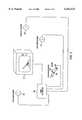
- FIG. 1shows a cross sectional profile of one configuration of the sword game of the present invention.
- Sword housing 200power supply 900, power supply cord 910, data link to game controller 510, control logic 499, voltage control circuits for the motors and sensor inputs 400, gyrostat position detector circuit and positional gyroscope 600, safety switch 201, safety switch lever 202, propulsion gyroscope device 500, Speaker 203, infrared receivers and/or blasters 300, 302 and 304. It is understood that the infrared detectors and blasters are interchangeable into different operable configurations.
- FIG. 2shows a detailed diagram of control circuit 400 and the propulsion gyrostat device 500.
- FIG. 3shows a configuration of the present invention showing the game controller remote infrared blasters, television display, game controller and the sword device 200 of the present invention.
- FIG. 4shows a block diagram of control circuit 400, showing the controller output and sensor input.
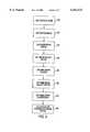
- FIG. 5shows a block diagram of the calculate blow routine which among other things, is a routine called from the game software to calculate the severity of a sword blow.
- FIG. 6shows a block diagram of a procedure for outputting the sword blow to the propulsion gyrostat 500.
- FIG. 7shows a block diagram of the gyro position control procedural loop which controls the position and the torque on the propulsion gyrostat.
- FIG. 8is a block diagram showing the mysterious force procedure which is a part of the integration between the game software and the sword hardware apparatus of the present invention.
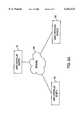
- FIG. 9Ais a block diagram showing a networked application of the present invention.
- FIG. 9Bshows a message protocol format that may be used in a multiplayer configuration.
- FIG. 10shows a depiction of the sword apparatus in sword contact with a virtual opponent.
- the sword game of the present inventionhas a sword housing 200 not to scale which is preferably made of a plastic material that is light weight yet strong enough to handle the forces imparted by the propulsion gyrostat.
- the torque forces from the present inventionmay be able to approximate the feel of a real sword battle, therefore, the material for the housing, 200, should be of sufficient strength to safely handle the torque imparted by the torque propulsion system 500.
- the sword housing 200may be made of metal, cast aluminum, plastic or other materials known. to those in the art, for handling this amount of torque.
- the housing 200may also serve as a safety enclosure if the propulsion gyrostat contained in block 500 were to have catastrophic failure and become free of its bearings.
- Block 900represents an external power supply.
- the power supply 900may be used to rectify household voltage into usable voltages for the sword game of the present invention.
- the sword apparatus of the present inventionmay have sufficient current draw to require a separate power supply and this current draw may not be available from the voltage outputs from a standard personal computer and/or game controller device.
- the high current draw of the present inventionmay be due to the high torque motors of propulsion gyrostat 500 necessary for the torque propulsion.
- power supply line 910may be coupled into the data line 510 to integrate power lines 910 and 510 into a single cord for data controls and power to the sword apparatus.
- power supply line 910may be coupled into the data line 510 to integrate power lines 910 and 510 into a single cord for data controls and power to the sword apparatus.
- the sword housing 200may be adapted to receive a speaker 203 to provide an audio output for game sounds.
- Speaker 203may be connected by line 204 to control circuits 400.
- Control circuits 400may contain a digital
- Block 499may represent the circuit board for the control circuits of the present invention.
- Control circuits 499may have a suitable communication means such as a USART and/or ethernet and/or universal serial bus interface to receive data signals from the game controller 240. It is within the scope of the present invention to use external circuits and use analog controls signals and/or wireless analog and/or digital control signal to provide an interface between the sword apparatus and the game controller 240.
- circuits 499may contain a suitable protocol communications device or procedure to establish communications between the sword device and game controller 240. Circuits 499 may also contain the processing elements necessary for control and/or execution of software and/or software elements to effect control of the sword apparatus of the present invention. The control functions and/or part or parts of the control function may be moved into the game controller 240.
- Block 400may represent the control circuits necessary for the analog drive voltages for the propulsion gyrostat means 500. It is understood that because of the high torque available from the propulsion gyrostat 500 separate control circuits such as high powered transistors and/or FETs may require separate circuits 400 to generate sufficiently large drive currents and/or voltages.
- the control circuits 400 and the digital control circuits and/or microprocessor circuit 499may be placed into a single integrated circuit, group of circuits and/or on the same circuit board.
- Block diagram element 600may represent a gyrostat positioning system to determine the attitude of the sword apparatus of the present invention.
- One such miniature deviceis commercially available from Sony Electronics and or functionally as the device employed in U.S. Pat. No. 4,959,725, the relevant herein incorporated by reference.
- Positional device element 600may be used to determine the position of the sword and the attitude of the sword in the X, Y and Z axes.
- Switch 201 and switch arm 202may be a safety switch, in the "deadman" circuit configuration, held in place by the player's grip on the apparatus.
- the gamemay be equipped with suitable straps, such as velcro straps and/or gloves, to maintain the sword within a player's hands and not allow the sword to flip out of a sword player's hands, much like a hand guard served in part, on traditional swords.
- the circular devices depicted at 300, 302 and 304may be either infrared receivers or infrared blasters or transmitters. These sensors and more, not shown, may extend around housing 200 to detect the position of a sword and/or the spatial coordinates of X, Y and Z as is denoted and further discussed in FIG. 3.
- block 400may contain the drive circuits necessary to drive the analog motors 20, 22 (not shown), 30, 35, 40 and 50.
- motors 30, 35, 40, 50, 20 and 22may be high torque motors such as those available from the radio controlled model cars and/or other devices from the hobby arts.
- motors 20 and 22may be high velocity motors capable of spinning the main propulsion flywheel 10 up to a sufficient velocity to impart the necessary torque to the player.
- the energy stored in the propulsion gyrostatis a factor of rotational velocity and the mass of the flywheel 10.
- flywheel 10 and motors 20 and 22may have mechanical assistance, e.g., gears, in rotating flywheel 10 and may also include a small transmission to help the motors 20 and 22 initially start the flywheel 10 and then shift gears into a higher speed to impart a greater rotation to flywheel 10.
- flywheel 10 and motors 20 and 22 and are the main inertial drives of the apparatusit is understood that a suitable high speed motor may be obtained from the disk drive technology arts wherein a very flat motor is available to spin a disk at a very high rotational speed.
- the main flywheel 10is shown mounted in a double gimballed configuration.
- the first gimbalbeing along an axes between motors 30 and 35.
- the second gimballed axesis between motors 40 and 50.
- Thisis a (two axes of freedom) double gimballed apparatus meaning that both "pitch” and "yaw" of the main propulsion flywheel 10 may be controlled in two axes of freedom.
- Other mechanical configurations of double gimballed gyroscopic apparatusare known to those skilled in the art and are within the scope of the present invention. It is also understood that a single gimballed embodiment is within the scope of the invention that may utilize two and/or more gyrostats.
- Two propulsion gyrostats in a single gimballed configurationmay be utilized by coordinating the toppling force on the two gyrostats to create the necessary torque action on the player desired by the present invention. It is also within the scope of the present invention to utilize two double gimballed gyrostats, one at the top of the sword and one at the bottom of the sword (not shown) in a "bar bell" like configuration. Such a dual gyrostatic propulsion configuration may be used to impart additional torque on the sword housing 200 to provide a more realistic simulation of the sword battle.
- Sensors 37 and 38are positional sensors that may be infrared and/or light-based sensors which may reflect off disks 100 and 90 respectfully.
- Disk 90 and disk 100may be reflectively "bar-coded" to indicate the position of the flywheel within the gimbals via the coding of the reflected light from sensors 37 and 38 off of the disks. These positional sensors may be necessary to obtain the position of the flywheel 10, e.g., the pitch and yaw position, in order to calculate which way the propulsion gyrostat should be toppled to create the desired torque.
- Contacts 110 and 95are shown as a means for transferring power and signals from the outer gimbal to the inner gimbal. Such power transfer may be accomplished by utilizing conductive metal ring fixated to disk 100 and disk 90 and pressure contacts at 110 and 95 keeping in contact with the conductive metal rings.
- the main propulsion gyrostatis shown at 10. Spokes 15 hold the propulsion gyrostat to the axes 60 of the main drive motor 20. It is understood that an additional drive motor 22 may also be used.
- Housing 70shows the housing of the first gimbal securing motor 20 and 22 and flywheel 10 to the first gimbal housing 70. The first housing 70 extends around to the mounting axles 31 and 32, connected to toppling motors 35 and 30 respectively.
- Drive motors 35 and 30may impart the toppling torque in the first gimballed axes. It is understood that motors 30 and 35 may be replaced with a single motor and that configuration is within the scope of the present invention.
- Circular ring 80depicts the second gimbal housing holding motors 30 and 35 to a second gimbal arrangement.
- the second gimbal housing 80connects the inner gimbal and motor drives 30 and 35 to the outer gimbal 80 through axles 81 and 82.
- Axles 81 and 82are connected to the second gimbal drive motors 40 and 50.
- a two motor configurationis shown as a means for imparting the maximum torque available from small electric motors such as those available from the hobby and toy arts.
- toppling motorsmay work in tandem to impart a toppling torque in the same direction, likewise motors 35 and 30 may also work in tandem to impart the maximum toppling effect on the drive gyrostat, the drive flywheel 10.
- motors 50 and 40may be replaced by a single suitably high torque motor. It is also within the scope of the present invention to use configurations that give motors 40 and 50 a mechanical advantage for toppling the drive flywheel 10 via the inner gimbal. Inner and outer gimbal brakes and/or clutches (not shown) may be used to temporarily lock a gimbal axes while a toppling force is applied to the second gimbal axes, such as disclosed in U.S. Pat. No. 5,437,420, the relevant portions herein again incorporated by reference.
- Function circuit board 400is shown as providing the analog drive voltages for the motors described above.
- FIG. 3shows the present invention in a deployment perspective showing a television and/or display 205 in a virtual reality and/or the game reality space can be projected 205 from game controller 240 in conjunction with sword housing 200.
- television 205may be replaced with a suitable display such as a high definition television and/or a computer display and game controller may be embodied in personal computer software and/or a personal computer hardware apparatus and/or dedicated hardware.
- Infrared blaster and/or receivers 210, 220 and 230may work in conjunction with infrared receivers and/or blasters 300, 302 and 304 to determine the position of the sword in real coordinates.
- the real coordinatesmay be determined by a timed burst from infrared blasters 210, 220 and 230 and the time delay of the burst received at any one of the sensors 300, 302 or 304 which may then be used to triangulate the position of the sword in real coordinates.
- television and/or display 205may be replaced with virtual reality glasses and/or helmet arrangement.
- the virtual reality glasses and/or helmetmay use two displays stereoscopically disposed in front of a player's eyes to give a three dimensional representation of the virtual playing field.
- infrared sensors 210, 220 and 230may be supplemented with additional infrared sensors to provide suitable determination of the real positional coordinates of the sword 200 and/or players head attitude and/or real position in respect to the virtual reality game.
- this positioning informationmay be used by the game to encourage the player to re-center the sword 200 and/or to keep the sword 200 in a predetermined playing field of the game.
- Infrared blastersshown at 210, 220 and 230 may be reversed, that is they may be infrared receivers and the infrared blaster may be located at 300, 302 and 304. In such a configuration a single and/or multiple infrared burst(s) may be output from 300, 302 and 304 and the timing of receiving or reception could be determined at 210, 220 and 230 in order to triangulate the real position of the sword 200.
- the gamehas a suitable calibration mode for configuring the sensor array.
- FIG. 4shows a block diagram of the control circuits 400 of the present invention.
- a controller 401may be used in conjunction with drive circuits at 402, 404 and 406 to provide the voltages and currents necessary to provide the energy for rotation of the propulsion gyrostat motor 20 and/or 22 (not shown) and toppling motors 30, 35, 40 and 50.
- Block 402may depict the main drive circuit for the rotation of the propulsion drive motor 20 and/or 22.
- Block 404may depict the drive circuitry for toppling motors 30 and 35.
- Block 406may depict the drive circuitry for toppling motors 40 and 50.
- blocks 404 and 406are representative of circuitry necessary to drive the high torque motors for the tumbling action of the present invention, these circuits may be incorporated into an application specific integrated circuit and/or incorporated with controller 401. They may also be discrete high current components such as MOSFET devices.
- Blocks 408 and 410are representative of the circuits necessary to determine the position of the propulsion drive 10 from sensors 37 and 38 respectively. Such sensors may include, as previously noted, sensors 37 and 38 as optical sensors that reflect off disks 100 and disk 90 respectively to determine the pitch and yaw position of propulsion drive 10. The circuits of blocks 408 and 410 may work in conjunction with controller 401 to determine the propulsion drive 10 position.
- Block 414may represent the circuitry necessary to work in conjunction with sensor 21 to determine the rotational velocity of propulsion drive 10.
- the rotational velocity of the propulsion drive motor 10may vary as game play ensues. Determining the rotational frequency of propulsion flywheel 10, may also be accomplished by measuring the reflected voltage from motor drive 20 and/or 22. The reflected voltage, current and/or power factor vector may be used to determine an approximate rotational velocity and/or speed of propulsion drive 10.
- Blocks 416, 418 and 420may represent the circuitry necessary for positional sensors 602, 604 and 606 to determine the pitch, yaw and/or attitude of the sword 200 when a mini-gyroscope is used to determine the position of the sword 200. Sensors 602, 604 and 606 may be incorporated into functional block 600.
- FIG. 5shows a block diagram representing a procedure that may be used to calculate a simulated sword blow.
- This routinemay make the initial calculation for the torque force to be applied to the pitch and yaw motor drives at outputs 404 and 406.
- the calculate blow routine 520may be called when an "attacking" sword and/or other virtual object(s) comes into contact with the calculated position for the player's virtual embodiment of the sword.
- the calculate blow routine 520 routinemay receive an impact point in the x, y, and z coordinates of the virtual space and when applicable the attacking sword velocity.
- Block 522 labeled "get position sword hilt"is a routine that may retrieve the actual position of a player's sword apparatus 200 from sensor 600 and/or by the other means of sensors 300, 302 and 304.
- the retrieved hilt pointmay be used to determine the distance from the sword hilt that a sword impact occurred. This distance may, in turn, be used to determine the amount of leverage, e.g., the amount of "twisting force", that the attacking sword blow may have on the sword apparatus 200.
- the next block 524may calculate the sword's idealized mass.
- sword apparatuswith different mass flywheels and/or rotational frequency
- the sword's idealized massmay be derived, at least in part, from a variable mass M, which may be the actual mass of the propulsion gyrostat and the variable omega which may be the instantaneous and/or present angular velocity and/or rotational frequency of the propulsion gyrostat.
- a variable mass Mwhich may be the actual mass of the propulsion gyrostat
- omegawhich may be the instantaneous and/or present angular velocity and/or rotational frequency of the propulsion gyrostat.
- Block 526 labeled "get sword velocity vector”may determine the sword velocity vector, e.g., the direction and speed of the sword, by successively determining the position of the player's sword and then determine from the change in position the velocity of the sword apparatus 200.
- the virtual swordmay have an idealized and/or virtual mass that is different from the actual mass and/or inertial mass of the actual apparatus 200.
- the virtual massmay be represented and/or idealized as a heavy broad sword. Since a real broadsword may be a very heavy instrument, its virtual mass may also have a certain amount of momentum because of its idealized weight and velocity.
- the resultant of procedural blocks 524 and 526is a vector providing the player's virtual sword direction and force at the impact point.
- the next procedural block 528 "get game sword position"yields a value from the game software, much like the resultant from procedural blocks described above, which provides the position of the sword hilt from the attacking virtual sword.
- Block 530 labeled “get game sword velocity vector”is a vector, from the game software, providing the velocity and virtual mass of the attacking sword, similar to procedural blocks 524 and 526 described above.
- the virtual attacking swordmay also have a virtual mass idealized from a fictionalized attacking broad sword. That is, once the heavy broad sword is in "motion", it may have a momentum from its mass and velocity.
- Procedural block 532 labeled "get game sword blow intensity”is the force of the attacking blow at the position of the strike.
- the results of procedural blocks 528, 530 and 532is a vector providing the direction and force at the impact point of both the attacking virtual sword and the virtual sword projected from the player's sword apparatus 200. By taking the cross product of these vectors, the factors such as angle of the sword attack, how far from the hilt the strike may be taken into account when calculating the resultant vectors.
- procedural block 534 labeled "calculated blow/return blow torque vector”is a product of the two vectors, that is, the vector providing the player's sword direction and force at the impact point and the attacking sword vector providing the direction and force of the impact point idealized at right after impact.
- the two swordsmay "bounce" off each other with an idealized impact.
- FIG. 6shows the call sword blow procedure which is used in conjunction with the procedures of FIG. 5 to calculate the actual values of the torque outputs for the pitch and yaw gyrostat toppling motors that provides the simulated impact of the sword at the player's sword apparatus 200.
- Procedural block 540 labeled "call sword blow”may denote the name of the software routine to perform the aforementioned torque output calculations.
- step by step procedural blocks, 542 labeled "get gyro position”may be from sensors 408 and 410 and may determine the attitude of the position of the propulsion gyrostat 10. This calculation may be important for the torque calculation because the gyrostatic force acts at a right angle to which the toppling force is applied.
- the toppling torque applied to the propulsion gyrostatmay be applied at a right angle to the propulsion gyrostat to achieve the desired torque effect.
- the next block 544 labeled “get gyro rotation”may be from sensor 418 and may indicate the angular velocity and/or rotational speed of the propulsion gyrostat 10.
- the next procedural block 546 labeled “get calibration factors”may provide operating parameters for the particular sword apparatus for which the torque output calculation is being determined. For example, as discussed above, a sword apparatus with two or more propulsion gyrostats is within the scope of the present invention.
- block 546may be utilized to retrieve the particular calibration factors for the particular sword apparatus for which the torque calculations are being calculated. It is understood that the calibration parameters may be encoded in a memory location associated with and/or within controller 401.
- the actual inertial mass of the swordwhich is the rotational frequency of the propulsion gyrostat times the mass of the propulsion gyrostat, may be greater than the virtual mass and/or idealized mass of the sword in order to provide excess torque and game action capacity for sword blows, e.g, at any given moment in game play the rotational frequency of the propulsion gyrostat may not be at the maximum rotational frequency and, therefore, the maximum torque effect on the sword apparatus may not be instantaneously available.
- the next procedural block 548may calculate the value of the torque for output to controllers 404 and 406.
- This calculationmay use the instantaneous inertial mass available, the desired torque amount and a compensating factor to resolve any non-linearities in the toppling motor response, as determined by conventional control systems principals, to calculate the output value.
- the sum of these torquesmay provide a toppling force at a right angle to the desired torque for the sword apparatus 200.
- the next procedural block 550 labeled "output impulse torque 1 and torque 2"are numerical value that may represent a value for eventual output to the toppling motors.
- these torque valuesare output to a predetermined memory location in controller 401 that, as will be discussed further below, are accessed by the gyrostat position control routine detailed in FIG. 7.
- torque 1 and torque 2may be a vector and/or an angular equation that takes into account the rotation of the propulsion gyrostat as torque is applied in order to translate what may be an angular torque output, due to the change in the angular position of the propulsion gyrostat, to translate the toppling force into a linear and/or straight line torque effect on the sword apparatus 200.
- Procedural block 552 labeled "gyro position control"denotes that the values of block 550 may be output to a memory location and/or data buffer and/or queue that will be accessed by the gyrostat position control routine detailed in FIG. 7.
- Procedural block 552also provides that the call sword blow routine 540 may then terminate normally and exit and/or return.
- FIG. 7shows the gyrostat position control procedure 560.
- the gyrostat position control proceduremay be the control loop that controls the output to torque control 404 and 406 and governs the position and/or toppling of the propulsion gyroscope 10.
- the gyrostat position control proceduremay operate in a continuous loop and may be the master routine that takes into account the sword blow torque and the "mysterious force factor", as will be discussed below, and the torque output required to cancel the force of a player rotating the sword apparatus 200 when no torque and/or tactile feedback or output on the sword apparatus 200 is desired.
- procedural block 562 labeled “initialize position”may provide that when the sword is initially powered on this procedure moves the propulsion gyrostat to an initial position. For example, “toppling” or rotating the propulsion gyrostat to top dead center while it initially spins up. This may be used to initially provision software variables in the game controller 240.
- Procedural block 564 "get sword position”may be the sword position from block 600 and/or sensors array in the 300 series which may be used to determine the sword device 200 position.
- Block 566may be a wait state that may be used to pause the procedural loop.
- Procedural block 568 labeled "get sword position”which may be a routine that may be identical to block 564 and may be used to get a second sword position.
- Procedural block 570may use the first position from procedural block 564 and the second sword position 568 to calculate the change and/or delta in the sword apparatus 200 position, that is, the change and/or attitude in the position of the sword apparatus 200.
- Procedural block 572 "get gyro position"may determine, from sensors 408 and 410, the position of the propulsion gyrostat 10.
- Procedural block 574may be used to calculate the tracking torque 1 and torque 2, although it is labeled "tracking torque" it may actually be a tracking voltage that topples the propulsion gyrostat to compensate for the change in the sword position from the first sword position calculated at 564 and the second sword position determined at 568.
- the tracking voltagemay be used to topple the propulsion gyrostat in such a way as to track the position of the sword apparatus 200 so as to minimize the torque felt at the sword apparatus 200 in response to movement of the apparatus, e.g., by the player, when no torque is desired.
- the toppling motors in the relaxed and/or non-energized state in conjunction with any mechanical advantage mechanism used to couple the toppling motors to the propulsion gyrostat flywheel 10may allow the propulsion gyrostat sufficient freedom of rotation so as to not require the tracking voltage output.
- the propulsion gyrostatwere to remain fixed and the player moved and/or changed the attitude of the sword apparatus 200, the player may feel an undesired torque at a right angle to the rotational force applied by the player.
- the mechanical linkagegenerally denoted in FIG. 2, may provide a predetermined mechanical degree of freedom in the coupling of the toppling motors with the propulsion flywheel 10.
- the predetermined degree of freedommay be used by the gyrostat position control routine 560 to provide a delay and/or predetermined degree of mechanical freedom to allow the calculation of the tracking voltages from block 574 to rotate and/or to allow the propulsion gyrostat to rotate and track the player's movement of the sword apparatus 200 without the player receiving an untoward amount of undesirable tactile feedback.
- the tracking voltage calculationmay only be an approximate calculation and yet be a mitigating factor for undesirable torque effect, e.g., some residual torque felt by the player may actually add a desirable strangeness of the tactical feel of the sword apparatus 200.
- the next procedural block 580 labeled "get gyro effects"accesses the torque calculated for the sword blow, from FIG.
- Procedural block 580"get gyro effects" calculates the sum of the tracking voltages from block 574, the sword blow torque from FIG. 6 and the mysterious force torque from FIG. 8 to combine these three torque vectors to determine a tracking voltage and/or voltages to create the toppling torque for the propulsion gyrostat 10.
- Block 582outputs torque voltages 1 and torque voltages 2 to torque motor controllers 404 and 406. These torque voltages are used to topple the propulsion gyrostat 10 of the present invention to provide the gyrostatic effect of the sword apparatus 200.
- the output at block 582may merely be the tracking torques from block 574 that attempts to topple the propulsion gyrostat so as to track the player's movement of sword apparatus 200.
- the dominant factor in the gyro effects calculation 580 and, therefore, the output at 582may be the sword blow providing a strong output providing a strong torque at the sword apparatus 200.
- the dominant forcemay be the "mysterious" force from FIG. 8, which will be discussed further below, which attempts to lead the player's sword movement through what may be subtle torque on the sword apparatus 200.
- the "mystery" torquemay be strong or subtle on sword apparatus 200 depending on pre-programmed parameters.
- Procedural block 584checks whether the controller 401 has issued a shut down command, if yes, the gyrostat position control loop exits at 586, if no, the procedure is passed to sword position routine 564 and the control loop goes on continuously (that is, until a shut down command is received).
- the check shutdown routine 584may check the dead-man switch shown as FIG. 1, switch 201, as to whether the player still has a sword in his hands and whether the controller may continue to output torque.
- FIG. 8shows the "mysterious" force calculation at procedural block 590.
- the mysterious force in the light saber metaphormay be a fanciful force as fictionalized in the Star WarsTM story line that the sword apparatus 200 will actually lead the player to a future sword impact.
- Another use of the "mysterious" forcemay be for a swordsman training mode to teach sword fighting techniques.
- the mysterious force calculationmay be performed at procedural block 591 by first getting a desired virtual x, y, and z point for the virtual sword.
- the game softwareprovides this coordinate as it, by definition, is a point and/or coordinate wherein an game event will occur within the game domain's future.
- Procedural block 592may determine the sword apparatus 200 base point, as discussed above, from sensors 600 gyrostatic determination and/or sensors 300 external determination.
- the base pointis understood to be the hilt of the sword apparatus 200 and/or the sword handle of sword apparatus 200.
- Procedural block 593may get the sword position or attitude, e.g., the angular position of the sword apparatus 200 and, thus, may determine the virtual location of the virtual sword blade extending from the sword apparatus 200.
- Procedural block 594may calculate the smallest change in position of the virtual sword location to the game provided X, Y and Z coordinates, e.g., some "future event.”
- Procedural block 595may calculate a torque for the necessary pitch and yaw for the propulsion gyrostat, which may calculate a torque to move the virtual sword to intersect the desired X, Y and Z coordinate and/or provide a torque in the direction of the desired X, Y, and Z coordinates.
- Block 596is the mysterious force factor parameter which may be a constant that is multiplied by the torque from block 595 to provide a mysterious force that is either strong, if the mysterious force factor is a large number, or subtle if the mysterious force factor is a small constant.
- the game metaphor and/or plot linemay be adapted to provide the player additional incentive to have a subtle mysterious force factor, again, to coordinate the game play and/or the plot with the conservation of the angular momentum of the propulsion gyrostat.
- the next procedural block 597may output a torque for controllers 404 and 406 to the gyro position control procedure depicted in FIG. 7. It is understood that this torque calculation may take into account the position of the propulsion gyrostat from sensor circuits 408 and 410 as well as the angular momentum of the propulsion gyrostat from sensor circuit 414 and as well as taking into account the mass factors from the controller for the particular propulsion gyrostat used by the particular sword apparatus 200.
- Procedural block 597may output the mysterious force torque via a memory location or other suitable buffer structure back to FIG. 7 as previously discussed.
- this routinemay be configured so as to accept other factors that may effect the sword blow calculation, such as to accommodate for when the sword apparatus 200 for the virtual sword apparatus passes through an object in the game domain such as a tree or wall that as previously discussed in the light saber metaphor and thereby may allow the sword to pass through or strike through while providing some tactile feedback to the sword apparatus 200 denoting the striking through of an object.
- Thismay be accomplished by reducing the sword blow intensity factor to provide an impulse from an object, e.g., idealized as a very small virtual mass, that may allow the sword apparatus idealized momentum to strike through the object. That is, the conservation of momentum equations may allow the virtual sword to follow through an object when the object struck has a small mass relative to the virtual sword mass.
- a comprehensive output for motor controller 404 and 406 to control the propulsion gyrostatmay be accomplished through these inter-related demands on the sword movement and/or interactions with the game plot and/or game play metaphor to give a player the incentive to conserve angular momentum of the sword apparatus 200.
- a comprehensive controller outputis disclosed and allows sword apparatus 200 to be completely controlled by the game controller 240 at FIG. 3.
- FIG. 9Ashows the game controllers of the present invention in a network configuration.
- Game controller 702may be configured as the master and game controllers 704 and 706 may be in a slave configuration.
- a network 708is shown which may be a TCP/IP network such as the Internet.
- the game station programmed as the mastersends, receives and coordinates the information transfer from the "slave" configured stations. Information may be transferred between the stations using the communication data packet shown in FIG. 9B.
- the communication packetprovides a terminal identification 750, position information for a sword apparatus 752, attitude information for a sword apparatus 754, velocity information for a sword apparatus 756, resultant force vector information 758 and sword parameter information 760.
- the slave configured game stationmay periodically send this information packet to the master configured game controller.
- the master configured game controllermay in turn, use this information to generate a virtual opponent having a virtual sword representation that is mapped into the game space.
- the master configured game stationmay relay the information from a first slave configured game terminal to a second slave configured game terminal.
- the master configured game stationcoordinates the calculation of the resultant force vector for the slave configuration game station's control output. It is understood that data packet shown in 9B may be framed with the suitable protocol overhead and transparent bits.
- sword apparatus 200is shown in a player's hand 1000 in combat with a virtual sword 1002 and virtual opponent 1004.
- a virtual sword bladeis shown at 1006 as idealized as extending from the sword apparatus 200 as may be viewed through virtual reality goggles on a player's 1000 eyes.
- the opponent's sword 1002 opponent 1004 and opponent sword blade 1008are, in this example, a virtual representation.
- the game controller 240may track the position and attitude of sword apparatus 200.
- the positional and attitude informationmay be used by the game controller software to project and track the virtual blade 1006.
- the game controller software 240may determine and track the velocity of the blade 1006 by using the differential positioning method described above.
- the game controller 240 softwaremay also create and track the position of blade 1006 in the game space coordinate system.
- the game controller 240may create and track the position of blade 1008.
- the game controller softwaremay determine when the position information of blade 1006 and the position information of blade 1008 indicates a collision of the blades by tracking the area from line 1014 which has a radius 1018 and the area from line 1016 which has a radius 1020 and logically comparing the points to determine whether there is an intersection.
- the intersection pointmay be passed to the procedures described above in FIGS. 5, 6 and 7.
- a vector 1012is determined that provides the force of the sword blow, for blade 1006, at the point of intersection.
- a vector 1010is also determined providing the force of the attacking sword at the point of intersection.
- a resultant vector 1022may be determined to provide the force vector for the resultant force at the point of intersection.
- the vector 1024may also be calculated with the conservation of energy equations to provide the resultant force at the intersection point for the attacking sword 1002.
- the resultant force vector 1022may be used in conjunction with the distance between the point of intersection and the sword hilt 1026 to approximate the torque generated at the point the player 1000 is gripping the sword apparatus 200.
- the torqueis the distance times the force vector 1022.
- This torque output approximationmay be used, inter alia, by the procedures described above to calculate the output torques and/or toppling force for the propulsion gyrostat.
- the above described proceduresoften use vectors and Cartesian coordinates to describe the present invention. Other coordinate systems such as spherical and cylindrical are also within the scope of the present invention.
Landscapes
- Engineering & Computer Science (AREA)
- Multimedia (AREA)
- Human Computer Interaction (AREA)
- General Engineering & Computer Science (AREA)
- Theoretical Computer Science (AREA)
- Physics & Mathematics (AREA)
- General Physics & Mathematics (AREA)
- Acoustics & Sound (AREA)
- Toys (AREA)
- User Interface Of Digital Computer (AREA)
Abstract
Description
Claims (35)
Priority Applications (6)
| Application Number | Priority Date | Filing Date | Title |
|---|---|---|---|
| US08/977,806US6162123A (en) | 1997-11-25 | 1997-11-25 | Interactive electronic sword game |
| US09/665,669US6902482B1 (en) | 1997-11-25 | 2000-09-20 | Interactive electronic game having gyroscopic output effect |
| US10/971,349US7247097B2 (en) | 1997-11-25 | 2004-10-22 | Electronic sword game with input and feedback |
| US11/772,703US7871330B2 (en) | 1997-11-25 | 2007-07-02 | Electronic sword game with input and feedback |
| US12/965,485US8485903B2 (en) | 1997-11-25 | 2010-12-10 | Electronic gaming device with feedback |
| US13/943,575US8777748B2 (en) | 1997-11-25 | 2013-07-16 | Electronic gaming device with feedback |
Applications Claiming Priority (1)
| Application Number | Priority Date | Filing Date | Title |
|---|---|---|---|
| US08/977,806US6162123A (en) | 1997-11-25 | 1997-11-25 | Interactive electronic sword game |
Related Child Applications (1)
| Application Number | Title | Priority Date | Filing Date |
|---|---|---|---|
| US09/665,669ContinuationUS6902482B1 (en) | 1997-11-25 | 2000-09-20 | Interactive electronic game having gyroscopic output effect |
Publications (1)
| Publication Number | Publication Date |
|---|---|
| US6162123Atrue US6162123A (en) | 2000-12-19 |
Family
ID=25525532
Family Applications (6)
| Application Number | Title | Priority Date | Filing Date |
|---|---|---|---|
| US08/977,806Expired - LifetimeUS6162123A (en) | 1997-11-25 | 1997-11-25 | Interactive electronic sword game |
| US09/665,669Expired - LifetimeUS6902482B1 (en) | 1997-11-25 | 2000-09-20 | Interactive electronic game having gyroscopic output effect |
| US10/971,349Expired - Fee RelatedUS7247097B2 (en) | 1997-11-25 | 2004-10-22 | Electronic sword game with input and feedback |
| US11/772,703Expired - Fee RelatedUS7871330B2 (en) | 1997-11-25 | 2007-07-02 | Electronic sword game with input and feedback |
| US12/965,485Expired - Fee RelatedUS8485903B2 (en) | 1997-11-25 | 2010-12-10 | Electronic gaming device with feedback |
| US13/943,575Expired - Fee RelatedUS8777748B2 (en) | 1997-11-25 | 2013-07-16 | Electronic gaming device with feedback |
Family Applications After (5)
| Application Number | Title | Priority Date | Filing Date |
|---|---|---|---|
| US09/665,669Expired - LifetimeUS6902482B1 (en) | 1997-11-25 | 2000-09-20 | Interactive electronic game having gyroscopic output effect |
| US10/971,349Expired - Fee RelatedUS7247097B2 (en) | 1997-11-25 | 2004-10-22 | Electronic sword game with input and feedback |
| US11/772,703Expired - Fee RelatedUS7871330B2 (en) | 1997-11-25 | 2007-07-02 | Electronic sword game with input and feedback |
| US12/965,485Expired - Fee RelatedUS8485903B2 (en) | 1997-11-25 | 2010-12-10 | Electronic gaming device with feedback |
| US13/943,575Expired - Fee RelatedUS8777748B2 (en) | 1997-11-25 | 2013-07-16 | Electronic gaming device with feedback |
Country Status (1)
| Country | Link |
|---|---|
| US (6) | US6162123A (en) |
Cited By (99)
| Publication number | Priority date | Publication date | Assignee | Title |
|---|---|---|---|---|
| US6374208B1 (en)* | 1999-03-11 | 2002-04-16 | Robert D. Ferris | System and method for adapting a PC-based application to an automated format |
| US20020082079A1 (en)* | 2000-12-22 | 2002-06-27 | Jani Mantyjarvi | Method for controlling a terminal display and a terminal |
| US20020151337A1 (en)* | 2001-03-29 | 2002-10-17 | Konami Corporation | Video game device, video game method, video game program, and video game system |
| US20020191011A1 (en)* | 2001-06-04 | 2002-12-19 | Firooz Rasouli | Virtual remote touch system |
| US6524186B2 (en)* | 1998-06-01 | 2003-02-25 | Sony Computer Entertainment, Inc. | Game input means to replicate how object is handled by character |
| US20030078086A1 (en)* | 2001-10-19 | 2003-04-24 | Konami Corporation | Game device, and game system |
| US20040009814A1 (en)* | 2000-08-31 | 2004-01-15 | Sung-Ha Kim | Whole-body controlling apparatus for fight game |
| US20040038730A1 (en)* | 2001-09-28 | 2004-02-26 | Satoshi Suda | Video slot gaming machine |
| US20040063480A1 (en)* | 2002-09-30 | 2004-04-01 | Xiaoling Wang | Apparatus and a method for more realistic interactive video games on computers or similar devices |
| US20040092311A1 (en)* | 2002-04-05 | 2004-05-13 | Weston Denise Chapman | Live-action interactive adventure game |
| FR2848870A1 (en)* | 2002-12-18 | 2004-06-25 | Sylvius | Electronic game system with an actuator element whose movement and attitude is used to control the movement of virtual elements on a display |
| EP1460521A2 (en) | 2003-03-19 | 2004-09-22 | Alps Electric Co., Ltd. | Force-feedback input device |
| WO2004111819A1 (en)* | 2003-06-09 | 2004-12-23 | Immersion Corporation | Interactive gaming systems with haptic feedback |
| US20050076161A1 (en)* | 2003-10-03 | 2005-04-07 | Amro Albanna | Input system and method |
| US20050080714A1 (en)* | 2003-09-30 | 2005-04-14 | Cmarket, Inc. | Method and apparatus for combining items in an on-line charitable auction or fund raising event |
| US20050085298A1 (en)* | 1997-11-25 | 2005-04-21 | Woolston Thomas G. | Electronic sword game with input and feedback |
| WO2005033888A3 (en)* | 2003-10-03 | 2005-09-15 | Qmotions Inc | Input system and method |
| US20050228744A1 (en)* | 2004-04-09 | 2005-10-13 | Cmarket, Inc. | Method and apparatus for modifying the winning bid in an on-line auction to benefit a charitable organization |
| US20050228742A1 (en)* | 2004-04-09 | 2005-10-13 | Cmarket, Inc. | Method and apparatus for creating and conducting on-line charitable fund raising activities with competitive events |
| US20050228746A1 (en)* | 2004-04-09 | 2005-10-13 | Cmarket, Inc. | Method and apparatus for contribution based placement of donor advertisements |
| US20050228745A1 (en)* | 2004-04-09 | 2005-10-13 | Cmarket, Inc. | Method and apparatus for conducting on-line auction events in coordination with incentive promotion for bidders |
| US20050246265A1 (en)* | 2004-04-09 | 2005-11-03 | Cmarket, Inc. | Method and apparatus for assigning value to an item donated to an on-line charitable auction or fund raising event |
| US7029400B2 (en) | 2002-08-01 | 2006-04-18 | Creative Kingdoms, Llc | Interactive water attraction and quest game |
| US7070500B1 (en)* | 1999-09-07 | 2006-07-04 | Konami Corporation | Musical player-motion sensing game system |
| US20060148563A1 (en)* | 2005-01-04 | 2006-07-06 | Pixart Imaging Inc. | Gaming peripheral apparatus for a gaming computing device |
| US7113193B2 (en) | 2000-07-21 | 2006-09-26 | Sony Computer Entertainment Inc. | Method for color transition detection |
| US20070043629A1 (en)* | 2004-09-29 | 2007-02-22 | Cmarket, Inc. | Method and apparatus for creating a catalog for an on-line charitable auction or fund raising event from a virtual consignment database in accordance with an organization profile |
| US20070060245A1 (en)* | 2005-08-19 | 2007-03-15 | Wms Gaming Inc. | Wagering game with preview feature for a winning payline |
| US20070066396A1 (en)* | 2002-04-05 | 2007-03-22 | Denise Chapman Weston | Retail methods for providing an interactive product to a consumer |
| US20070139375A1 (en)* | 1995-12-01 | 2007-06-21 | Immersion Corporation | Providing force feedback to a user of an interface device based on interactions of a user-controlled cursor in a graphical user interface |
| US20070191116A1 (en)* | 2003-12-09 | 2007-08-16 | Gardiner Adrian B | Game |
| US20080065513A1 (en)* | 2006-08-31 | 2008-03-13 | Cmarket, Inc. | Method and apparatus for sponsoring a consignable item in an on-line charitable auction or fund raising event |
| US20080070682A1 (en)* | 2006-08-15 | 2008-03-20 | Nintendo Of America Inc. | Systems and methods for providing educational games for use by young children, and digital storage mediums for storing the educational games thereon |
| US20080192070A1 (en)* | 2002-02-07 | 2008-08-14 | Microsoft Corporation | Manipulating objects displayed on a display screen |
| US20080192005A1 (en)* | 2004-10-20 | 2008-08-14 | Jocelyn Elgoyhen | Automated Gesture Recognition |
| US7445550B2 (en) | 2000-02-22 | 2008-11-04 | Creative Kingdoms, Llc | Magical wand and interactive play experience |
| US20080280660A1 (en)* | 1999-10-04 | 2008-11-13 | Ssd Company Limited | Sensing ball game machine |
| US7488231B2 (en) | 2000-10-20 | 2009-02-10 | Creative Kingdoms, Llc | Children's toy with wireless tag/transponder |
| US20090048069A1 (en)* | 2007-08-13 | 2009-02-19 | Richard Sheedy | Boxing device and related methods |
| US7500917B2 (en)* | 2000-02-22 | 2009-03-10 | Creative Kingdoms, Llc | Magical wand and interactive play experience |
| EP1933284A3 (en)* | 2006-12-11 | 2009-04-01 | Kabushiki Kaisha Square Enix (also trading as Square Enix Co., Ltd.) | Game device, game advancing method, program, and recording medium |
| US20090096714A1 (en)* | 2006-03-31 | 2009-04-16 | Brother Kogyo Kabushiki Kaisha | Image display device |
| US7591703B2 (en) | 2006-06-09 | 2009-09-22 | Mattel, Inc. | Interactive DVD gaming systems |
| US7614958B2 (en) | 2001-11-16 | 2009-11-10 | Creative Kingdoms, Llc | Interactive quest game |
| US20090280901A1 (en)* | 2008-05-09 | 2009-11-12 | Dell Products, Lp | Game controller device and methods thereof |
| US7636080B2 (en) | 1995-12-01 | 2009-12-22 | Immersion Corporation | Networked applications including haptic feedback |
| US20100007528A1 (en)* | 2008-07-11 | 2010-01-14 | Nintendo Co., Ltd. | Expanding operating device and operating system |
| US7674184B2 (en) | 2002-08-01 | 2010-03-09 | Creative Kingdoms, Llc | Interactive water attraction and quest game |
| US7749089B1 (en) | 1999-02-26 | 2010-07-06 | Creative Kingdoms, Llc | Multi-media interactive play system |
| US20100248844A1 (en)* | 2009-03-25 | 2010-09-30 | Souichi Nakajima | Game apparatus and recording medium recording game program |
| US20100292007A1 (en)* | 2007-06-26 | 2010-11-18 | Nintendo Of America Inc. | Systems and methods for control device including a movement detector |
| US7850527B2 (en) | 2000-02-22 | 2010-12-14 | Creative Kingdoms, Llc | Magic-themed adventure game |
| US7874918B2 (en) | 2005-11-04 | 2011-01-25 | Mattel Inc. | Game unit with motion and orientation sensing controller |
| US7878905B2 (en) | 2000-02-22 | 2011-02-01 | Creative Kingdoms, Llc | Multi-layered interactive play experience |
| US20110068937A1 (en)* | 2009-09-21 | 2011-03-24 | Hon Hai Precision Industry Co., Ltd. | Motion sensing controller and game apparatus having same |
| US20110309919A1 (en)* | 2010-06-22 | 2011-12-22 | Microsoft Corporation | Providing Directional Force Feedback In Freespace |
| US8133115B2 (en) | 2003-10-22 | 2012-03-13 | Sony Computer Entertainment America Llc | System and method for recording and displaying a graphical path in a video game |
| ITMI20102049A1 (en)* | 2010-11-04 | 2012-05-05 | Michele Antolini | APTIC DIRECTION INDICATOR |
| US8204272B2 (en) | 2006-05-04 | 2012-06-19 | Sony Computer Entertainment Inc. | Lighting control of a user environment via a display device |
| US8243089B2 (en) | 2006-05-04 | 2012-08-14 | Sony Computer Entertainment Inc. | Implementing lighting control of a user environment |
| US8284310B2 (en) | 2005-06-22 | 2012-10-09 | Sony Computer Entertainment America Llc | Delay matching in audio/video systems |
| US8289325B2 (en) | 2004-10-06 | 2012-10-16 | Sony Computer Entertainment America Llc | Multi-pass shading |
| US20120306750A1 (en)* | 2010-02-11 | 2012-12-06 | Igor Karasin | Gesture based computer interface system and method |
| US8330587B2 (en) | 2007-07-05 | 2012-12-11 | Tod Anthony Kupstas | Method and system for the implementation of identification data devices in theme parks |
| US8441444B2 (en) | 2000-09-28 | 2013-05-14 | Immersion Corporation | System and method for providing directional tactile sensations |
| US8461468B2 (en) | 2009-10-30 | 2013-06-11 | Mattel, Inc. | Multidirectional switch and toy including a multidirectional switch |
| US8485879B2 (en) | 2009-12-24 | 2013-07-16 | Jason McCarhy | Fight analysis system |
| US8508469B1 (en)* | 1995-12-01 | 2013-08-13 | Immersion Corporation | Networked applications including haptic feedback |
| US8542105B2 (en) | 2009-11-24 | 2013-09-24 | Immersion Corporation | Handheld computer interface with haptic feedback |
| US20130265434A1 (en)* | 2012-04-06 | 2013-10-10 | Canon Kabushiki Kaisha | Image processing apparatus and image processing method |
| US8651953B2 (en) | 2007-02-01 | 2014-02-18 | Mattel, Inc. | Electronic game device and method of using the same |
| US8696482B1 (en) | 2010-10-05 | 2014-04-15 | Swingbyte, Inc. | Three dimensional golf swing analyzer |
| US9086727B2 (en) | 2010-06-22 | 2015-07-21 | Microsoft Technology Licensing, Llc | Free space directional force feedback apparatus |
| US20150294480A1 (en)* | 2005-10-26 | 2015-10-15 | Sony Computer Entertainment Inc. | Control Device for Communicating Visual Information |
| US9211439B1 (en) | 2010-10-05 | 2015-12-15 | Swingbyte, Inc. | Three dimensional golf swing analyzer |
| US9342817B2 (en) | 2011-07-07 | 2016-05-17 | Sony Interactive Entertainment LLC | Auto-creating groups for sharing photos |
| CN105744339A (en)* | 2009-05-29 | 2016-07-06 | Lg电子株式会社 | Image display apparatus and operating method thereof |
| US9446319B2 (en) | 2003-03-25 | 2016-09-20 | Mq Gaming, Llc | Interactive gaming toy |
| US20170206709A1 (en)* | 2016-01-19 | 2017-07-20 | Disney Enterprises, Inc. | Systems and methods for augmenting an appearance of a hilt to simulate a bladed weapon |
| US20170203225A1 (en)* | 2016-01-19 | 2017-07-20 | Disney Enterprises, Inc. | Systems and methods for using a gyroscope to change the resistance of moving a virtual weapon |
| EP3216500A1 (en)* | 2016-03-07 | 2017-09-13 | HTC Corporation | Accessory management of virtual reality system |
| WO2017169040A1 (en)* | 2016-03-30 | 2017-10-05 | Sony Corporation | Information processing apparatus, information processing method, and non-transitory computer-readable medium |
| US20170282081A1 (en)* | 1999-05-12 | 2017-10-05 | Wilbert Quinc Murdock | Transmitting Sensor Data Created in a Game Environment to a Set of Processors Outside the Game Environment Based on Predefined Event Determinations |
| US20170358235A1 (en)* | 2013-05-03 | 2017-12-14 | John James Daniels | Accelerated Learning, Entertainment and Cognitive Therapy Using Augmented Reality Comprising Combined Haptic, Auditory, and Visual Stimulation |
| US10101157B2 (en) | 2015-09-14 | 2018-10-16 | Eric Bharucha | Free-space force feedback system |
| US10124210B2 (en) | 2015-03-13 | 2018-11-13 | KO Luxembourg SARL | Systems and methods for qualitative assessment of sports performance |
| US10213645B1 (en) | 2011-10-03 | 2019-02-26 | Swingbyte, Inc. | Motion attributes recognition system and methods |
| US10481680B2 (en) | 2018-02-02 | 2019-11-19 | Disney Enterprises, Inc. | Systems and methods to provide a shared augmented reality experience |
| US10546431B2 (en) | 2018-03-29 | 2020-01-28 | Disney Enterprises, Inc. | Systems and methods to augment an appearance of physical object for an augmented reality experience |
| US10587834B2 (en) | 2016-03-07 | 2020-03-10 | Disney Enterprises, Inc. | Systems and methods for tracking objects for augmented reality |
| US10786736B2 (en) | 2010-05-11 | 2020-09-29 | Sony Interactive Entertainment LLC | Placement of user information in a game space |
| US10916061B2 (en) | 2019-04-24 | 2021-02-09 | Disney Enterprises, Inc. | Systems and methods to synchronize real-world motion of physical objects with presentation of virtual content |
| US10918949B2 (en) | 2019-07-01 | 2021-02-16 | Disney Enterprises, Inc. | Systems and methods to provide a sports-based interactive experience |
| US10974132B2 (en) | 2018-10-02 | 2021-04-13 | Disney Enterprises, Inc. | Systems and methods to provide a shared interactive experience across multiple presentation devices based on detection of one or more extraterrestrial bodies |
| US11014008B2 (en) | 2019-03-27 | 2021-05-25 | Disney Enterprises, Inc. | Systems and methods for game profile development based on virtual and/or real activities |
| CN113209605A (en)* | 2021-06-04 | 2021-08-06 | 歌尔科技有限公司 | Force feedback device, gamepad and system |
| US11117033B2 (en) | 2010-04-26 | 2021-09-14 | Wilbert Quinc Murdock | Smart system for display of dynamic movement parameters in sports and training |
| US20220370897A1 (en)* | 2019-10-25 | 2022-11-24 | P&I Company | Fishing simulation apparatus and method |
| US11663783B2 (en) | 2016-02-10 | 2023-05-30 | Disney Enterprises, Inc. | Systems and methods for using augmented reality with the internet of things |
Families Citing this family (63)
| Publication number | Priority date | Publication date | Assignee | Title |
|---|---|---|---|---|
| US20060282873A1 (en)* | 2002-07-27 | 2006-12-14 | Sony Computer Entertainment Inc. | Hand-held controller having detectable elements for tracking purposes |
| US20060264260A1 (en)* | 2002-07-27 | 2006-11-23 | Sony Computer Entertainment Inc. | Detectable and trackable hand-held controller |
| US7782297B2 (en)* | 2002-07-27 | 2010-08-24 | Sony Computer Entertainment America Inc. | Method and apparatus for use in determining an activity level of a user in relation to a system |
| US8570378B2 (en) | 2002-07-27 | 2013-10-29 | Sony Computer Entertainment Inc. | Method and apparatus for tracking three-dimensional movements of an object using a depth sensing camera |
| US9393487B2 (en)* | 2002-07-27 | 2016-07-19 | Sony Interactive Entertainment Inc. | Method for mapping movements of a hand-held controller to game commands |
| US8313380B2 (en) | 2002-07-27 | 2012-11-20 | Sony Computer Entertainment America Llc | Scheme for translating movements of a hand-held controller into inputs for a system |
| US7665041B2 (en)* | 2003-03-25 | 2010-02-16 | Microsoft Corporation | Architecture for controlling a computer using hand gestures |
| US8745541B2 (en)* | 2003-03-25 | 2014-06-03 | Microsoft Corporation | Architecture for controlling a computer using hand gestures |
| US7510477B2 (en)* | 2003-12-11 | 2009-03-31 | Argentar Eric J | Control apparatus for use with a computer or video game system |
| US8070571B2 (en)* | 2003-12-11 | 2011-12-06 | Eric Argentar | Video game controller |
| EP1759529A4 (en) | 2004-04-30 | 2009-11-11 | Hillcrest Lab Inc | FREE SPACE POINTING DEVICE AND ASSOCIATED METHODS |
| CA2511058A1 (en)* | 2004-06-28 | 2005-12-28 | Morsonic Inc. | System and method for real time effects automation |
| US8137195B2 (en)* | 2004-11-23 | 2012-03-20 | Hillcrest Laboratories, Inc. | Semantic gaming and application transformation |
| WO2006099596A1 (en)* | 2005-03-17 | 2006-09-21 | Massachusetts Institute Of Technology | System for and method of motion and force synchronization with time delay reduction in multi-user shared virtual environments |
| JP4805633B2 (en) | 2005-08-22 | 2011-11-02 | 任天堂株式会社 | Game operation device |
| US7927216B2 (en) | 2005-09-15 | 2011-04-19 | Nintendo Co., Ltd. | Video game system with wireless modular handheld controller |
| US8313379B2 (en) | 2005-08-22 | 2012-11-20 | Nintendo Co., Ltd. | Video game system with wireless modular handheld controller |
| US8870655B2 (en) | 2005-08-24 | 2014-10-28 | Nintendo Co., Ltd. | Wireless game controllers |
| JP4262726B2 (en) | 2005-08-24 | 2009-05-13 | 任天堂株式会社 | Game controller and game system |
| US8308563B2 (en) | 2005-08-30 | 2012-11-13 | Nintendo Co., Ltd. | Game system and storage medium having game program stored thereon |
| US8157651B2 (en) | 2005-09-12 | 2012-04-17 | Nintendo Co., Ltd. | Information processing program |
| US20070093295A1 (en)* | 2005-10-26 | 2007-04-26 | Chii-Moon Liou | Wireless controller for game machine |
| US7752545B2 (en)* | 2006-03-15 | 2010-07-06 | Microsoft Corporation | Generator system |
| JP5330640B2 (en)* | 2006-05-09 | 2013-10-30 | 任天堂株式会社 | GAME PROGRAM, GAME DEVICE, GAME SYSTEM, AND GAME PROCESSING METHOD |
| USRE48417E1 (en) | 2006-09-28 | 2021-02-02 | Sony Interactive Entertainment Inc. | Object direction using video input combined with tilt angle information |
| US8781151B2 (en)* | 2006-09-28 | 2014-07-15 | Sony Computer Entertainment Inc. | Object detection using video input combined with tilt angle information |
| US8310656B2 (en)* | 2006-09-28 | 2012-11-13 | Sony Computer Entertainment America Llc | Mapping movements of a hand-held controller to the two-dimensional image plane of a display screen |
| US20080096657A1 (en)* | 2006-10-20 | 2008-04-24 | Sony Computer Entertainment America Inc. | Method for aiming and shooting using motion sensing controller |
| US20080096654A1 (en)* | 2006-10-20 | 2008-04-24 | Sony Computer Entertainment America Inc. | Game control using three-dimensional motions of controller |
| JP5177615B2 (en)* | 2006-12-01 | 2013-04-03 | 任天堂株式会社 | GAME PROGRAM, GAME DEVICE, GAME SYSTEM, AND GAME PROCESSING METHOD |
| US20090017910A1 (en)* | 2007-06-22 | 2009-01-15 | Broadcom Corporation | Position and motion tracking of an object |
| TW200833398A (en)* | 2007-02-09 | 2008-08-16 | Pixart Imaging Inc | Method and system of interactive game with warning function |
| TWI383825B (en)* | 2007-02-09 | 2013-02-01 | Pixart Imaging Inc | Interactive game method with alarm function and system thereof |
| US20080220693A1 (en)* | 2007-03-07 | 2008-09-11 | Cuisinier Jarret P | Toy sword device and game |
| US20090017799A1 (en)* | 2007-07-13 | 2009-01-15 | Sony Ericsson Mobile Communications Ab | System, device and method for transmitting a file by use of a throwing gesture to a mobile terminal |
| US20090093183A1 (en)* | 2007-09-01 | 2009-04-09 | Bernadine Marie Randle | Novelty light-up and action toy |
| US8574079B2 (en)* | 2007-11-13 | 2013-11-05 | Spielo International Canada, Ulc | Wireless wagering system |
| US8143729B2 (en)* | 2008-01-25 | 2012-03-27 | International Rectifier Corporation | Autoclave capable chip-scale package |
| US20100075284A1 (en)* | 2008-04-23 | 2010-03-25 | Maria Kozhevnikov | Three-Dimensional Perspective Taking Ability Assessment Tool |
| JP5430123B2 (en)* | 2008-10-30 | 2014-02-26 | 任天堂株式会社 | GAME DEVICE AND GAME PROGRAM |
| US20100304873A1 (en)* | 2009-05-28 | 2010-12-02 | Lipa Markowitz | Bowling Ball and Football Game Controller |
| USD603464S1 (en)* | 2009-06-26 | 2009-11-03 | Christopher Kelly | Illuminated toy light saber |
| IT1400209B1 (en)* | 2010-05-06 | 2013-05-24 | Lazzari | "TWO-WHEEL VEHICLE". |
| USD633959S1 (en)* | 2010-06-29 | 2011-03-08 | Hasbro, Inc. | Toy sword handle |
| WO2013025823A2 (en)* | 2011-08-17 | 2013-02-21 | The Regents Of The University Of California | Wearable device for noninvasive tactile stimulation |
| US8811938B2 (en) | 2011-12-16 | 2014-08-19 | Microsoft Corporation | Providing a user interface experience based on inferred vehicle state |
| US20150126260A1 (en)* | 2013-11-01 | 2015-05-07 | Levelup Incorporated | System and method for proximity and motion detection for interactive activity |
| USD749801S1 (en)* | 2013-12-11 | 2016-02-16 | Paul Michael James | Animal prod |
| US10022622B2 (en) | 2014-04-21 | 2018-07-17 | Steelseries Aps | Programmable actuation inputs of an accessory and methods thereof |
| CN105311809A (en)* | 2014-06-28 | 2016-02-10 | 冷庆林 | Abreaction wall |
| US10320622B2 (en)* | 2014-08-22 | 2019-06-11 | Vmware, Inc. | Policy declarations for cloud management system |
| WO2016205182A1 (en)* | 2015-06-15 | 2016-12-22 | Survios, Inc. | Systems and methods for immersive physical interaction with a virtual environment |
| US10272324B2 (en)* | 2015-12-24 | 2019-04-30 | Intel Corporation | Classifying collision events using inertial and audio data |
| WO2017178862A1 (en) | 2016-04-11 | 2017-10-19 | Berkovs Boriss | Method for modeling and simulating physical effect in interactive simulators and electronic games, system for implementing the same and method for calibrating the system |
| JP6877893B2 (en)* | 2016-06-06 | 2021-05-26 | 任天堂株式会社 | Game device, game system, game program, and swing input judgment method |
| US10290151B2 (en)* | 2016-08-17 | 2019-05-14 | Blackberry Limited | AR/VR device virtualisation |
| US11045738B1 (en) | 2016-12-13 | 2021-06-29 | Hasbro, Inc. | Motion and toy detecting body attachment |
| US10758828B1 (en) | 2017-03-17 | 2020-09-01 | Hasbro, Inc. | Music mash up collectable card game |
| US11946744B2 (en) | 2019-07-26 | 2024-04-02 | Hewlett-Packard Development Company, L.P. | Synchronization of a gyroscope in a virtual-reality environment |
| US11439902B2 (en) | 2020-05-01 | 2022-09-13 | Dell Products L.P. | Information handling system gaming controls |
| US11260297B2 (en) | 2020-05-01 | 2022-03-01 | Dell Products L.P. | Information handling system wheel input device |
| US11433314B2 (en) | 2020-05-01 | 2022-09-06 | Dell Products L.P. | Information handling system hands free voice and text chat |
| US12420176B2 (en)* | 2023-01-20 | 2025-09-23 | Sony Interactive Entertainment LLC | Systems and methods for a microphone input device and microphone accessibility features |
Citations (25)
| Publication number | Priority date | Publication date | Assignee | Title |
|---|---|---|---|---|
| US3877316A (en)* | 1971-06-09 | 1975-04-15 | Hughes Aircraft Co | Isolated frame on platform stabilized by spinning body |
| US3877662A (en)* | 1971-06-09 | 1975-04-15 | Gordon S Reiter | Isolated frame on platforms stabilized by spinning body |
| US4099714A (en)* | 1977-12-05 | 1978-07-11 | Willis Charles W | Fencing game set |
| US4573651A (en)* | 1983-12-19 | 1986-03-04 | Stanton Austin N | Torque orientation device |
| US4630817A (en)* | 1983-12-20 | 1986-12-23 | Gym Bee Enterprises, Inc. | Recreation apparatus |
| US4695953A (en)* | 1983-08-25 | 1987-09-22 | Blair Preston E | TV animation interactively controlled by the viewer |
| US4923142A (en)* | 1987-11-06 | 1990-05-08 | Thomson-Brandt Armements | Gyroscopic stabilizing device for a projectile control instrument |
| US4925189A (en)* | 1989-01-13 | 1990-05-15 | Braeunig Thomas F | Body-mounted video game exercise device |
| US4959725A (en)* | 1988-07-13 | 1990-09-25 | Sony Corporation | Method and apparatus for processing camera an image produced by a video camera to correct for undesired motion of the video camera |
| US5090260A (en)* | 1989-08-09 | 1992-02-25 | Delroy Mortimer S | Gyrostat propulsion system |
| US5131165A (en)* | 1991-02-21 | 1992-07-21 | Benson Richard T | Computerized depth calculator |
| US5138154A (en)* | 1990-04-04 | 1992-08-11 | Gyration Inc. | Shaft angle encoder with rotating off-axis interference pattern |
| US5145446A (en)* | 1991-09-23 | 1992-09-08 | Kuo Yi Yu | Retractable toy sword with video and sound effect |
| US5232223A (en)* | 1992-03-24 | 1993-08-03 | Larry Dornbusch | Electronic game controller |
| US5354057A (en)* | 1992-09-28 | 1994-10-11 | Pruitt Ralph T | Simulated combat entertainment system |
| JPH06301474A (en)* | 1993-04-14 | 1994-10-28 | Casio Comput Co Ltd | Position detector |
| US5437420A (en)* | 1993-07-16 | 1995-08-01 | Hughes Aircraft Company | High torque double gimbal control moment gyro |
| US5453758A (en)* | 1992-07-31 | 1995-09-26 | Sony Corporation | Input apparatus |
| JPH0810446A (en)* | 1994-06-29 | 1996-01-16 | Copcom Co Ltd | Input device for amusement and amusement device |
| US5516105A (en)* | 1994-10-06 | 1996-05-14 | Exergame, Inc. | Acceleration activated joystick |
| US5542672A (en)* | 1995-03-17 | 1996-08-06 | Meredith; Chris | Fishing rod and reel electronic game controller |
| US5667111A (en)* | 1995-06-07 | 1997-09-16 | Poly Pro, Division Of Roberts Systems, Inc. | Plastic pour-spout and container |
| US5713792A (en)* | 1995-01-30 | 1998-02-03 | Sega Enterprises, Ltd. | Fishing game device and a simulated fishing reel |
| US5741182A (en)* | 1994-06-17 | 1998-04-21 | Sports Sciences, Inc. | Sensing spatial movement |
| US5751273A (en)* | 1994-12-05 | 1998-05-12 | Cohen; Allen L. | Game controller for infants |
Family Cites Families (22)
| Publication number | Priority date | Publication date | Assignee | Title |
|---|---|---|---|---|
| US4395045A (en)* | 1980-06-16 | 1983-07-26 | Sanders Associates, Inc. | Television precision target shooting apparatus and method |
| JPS596079A (en)* | 1982-07-01 | 1984-01-13 | 三菱電機株式会社 | Swing measuring device |
| US4817950A (en)* | 1987-05-08 | 1989-04-04 | Goo Paul E | Video game control unit and attitude sensor |
| US5174759A (en)* | 1988-08-04 | 1992-12-29 | Preston Frank S | TV animation interactively controlled by the viewer through input above a book page |
| JPH02199526A (en)* | 1988-10-14 | 1990-08-07 | David G Capper | Control interface apparatus |
| CA2028290C (en)* | 1989-11-01 | 1996-12-17 | Aart Van Wingerden | Tray, apparatus and method for propagating, growing and handling plants |
| US5136154A (en)* | 1991-05-10 | 1992-08-04 | Advanced Fuel Research, Inc. | Method and system for photoconductive detector signal correction |
| US5185561A (en)* | 1991-07-23 | 1993-02-09 | Digital Equipment Corporation | Torque motor as a tactile feedback device in a computer system |
| US5442168A (en)* | 1991-10-15 | 1995-08-15 | Interactive Light, Inc. | Dynamically-activated optical instrument for producing control signals having a self-calibration means |
| TW359781B (en)* | 1993-05-25 | 1999-06-01 | Casio Computer Co Ltd | Animal image display controlling devices and method thereof |
| US5685776A (en) | 1994-11-23 | 1997-11-11 | Tiger Electronics, Inc. | Hand-held electronic game devices |
| US5667171A (en) | 1995-04-28 | 1997-09-16 | Hughes Aircraft Company | Satellite spin axis stabilization using a single degree of freedom transverse momentum storage device |
| US5913727A (en)* | 1995-06-02 | 1999-06-22 | Ahdoot; Ned | Interactive movement and contact simulation game |
| US5833549A (en)* | 1995-11-14 | 1998-11-10 | Interactive Light, Inc. | Sports trainer and game |
| US6028593A (en)* | 1995-12-01 | 2000-02-22 | Immersion Corporation | Method and apparatus for providing simulated physical interactions within computer generated environments |
| US5641288A (en)* | 1996-01-11 | 1997-06-24 | Zaenglein, Jr.; William G. | Shooting simulating process and training device using a virtual reality display screen |
| US5692956A (en) | 1996-02-09 | 1997-12-02 | Mattel, Inc. | Combination computer mouse and game play control |
| US5823845A (en)* | 1996-03-12 | 1998-10-20 | Kieran Bergin, Inc. | Mobile, gyroscopically stabilized toy with controlled multi-action movements |
| JPH114966A (en)* | 1996-10-01 | 1999-01-12 | Sony Computer Entateimento:Kk | Operation device for game machine and game device |
| US6042478A (en) | 1997-02-10 | 2000-03-28 | Tiger Electronics, Ltd. | Hand held video game |
| IL121178A (en)* | 1997-06-27 | 2003-11-23 | Nds Ltd | Interactive game system |
| US6162123A (en)* | 1997-11-25 | 2000-12-19 | Woolston; Thomas G. | Interactive electronic sword game |
- 1997
- 1997-11-25USUS08/977,806patent/US6162123A/ennot_activeExpired - Lifetime
- 2000
- 2000-09-20USUS09/665,669patent/US6902482B1/ennot_activeExpired - Lifetime
- 2004
- 2004-10-22USUS10/971,349patent/US7247097B2/ennot_activeExpired - Fee Related
- 2007
- 2007-07-02USUS11/772,703patent/US7871330B2/ennot_activeExpired - Fee Related
- 2010
- 2010-12-10USUS12/965,485patent/US8485903B2/ennot_activeExpired - Fee Related
- 2013
- 2013-07-16USUS13/943,575patent/US8777748B2/ennot_activeExpired - Fee Related
Patent Citations (25)
| Publication number | Priority date | Publication date | Assignee | Title |
|---|---|---|---|---|
| US3877316A (en)* | 1971-06-09 | 1975-04-15 | Hughes Aircraft Co | Isolated frame on platform stabilized by spinning body |
| US3877662A (en)* | 1971-06-09 | 1975-04-15 | Gordon S Reiter | Isolated frame on platforms stabilized by spinning body |
| US4099714A (en)* | 1977-12-05 | 1978-07-11 | Willis Charles W | Fencing game set |
| US4695953A (en)* | 1983-08-25 | 1987-09-22 | Blair Preston E | TV animation interactively controlled by the viewer |
| US4573651A (en)* | 1983-12-19 | 1986-03-04 | Stanton Austin N | Torque orientation device |
| US4630817A (en)* | 1983-12-20 | 1986-12-23 | Gym Bee Enterprises, Inc. | Recreation apparatus |
| US4923142A (en)* | 1987-11-06 | 1990-05-08 | Thomson-Brandt Armements | Gyroscopic stabilizing device for a projectile control instrument |
| US4959725A (en)* | 1988-07-13 | 1990-09-25 | Sony Corporation | Method and apparatus for processing camera an image produced by a video camera to correct for undesired motion of the video camera |
| US4925189A (en)* | 1989-01-13 | 1990-05-15 | Braeunig Thomas F | Body-mounted video game exercise device |
| US5090260A (en)* | 1989-08-09 | 1992-02-25 | Delroy Mortimer S | Gyrostat propulsion system |
| US5138154A (en)* | 1990-04-04 | 1992-08-11 | Gyration Inc. | Shaft angle encoder with rotating off-axis interference pattern |
| US5131165A (en)* | 1991-02-21 | 1992-07-21 | Benson Richard T | Computerized depth calculator |
| US5145446A (en)* | 1991-09-23 | 1992-09-08 | Kuo Yi Yu | Retractable toy sword with video and sound effect |
| US5232223A (en)* | 1992-03-24 | 1993-08-03 | Larry Dornbusch | Electronic game controller |
| US5453758A (en)* | 1992-07-31 | 1995-09-26 | Sony Corporation | Input apparatus |
| US5354057A (en)* | 1992-09-28 | 1994-10-11 | Pruitt Ralph T | Simulated combat entertainment system |
| JPH06301474A (en)* | 1993-04-14 | 1994-10-28 | Casio Comput Co Ltd | Position detector |
| US5437420A (en)* | 1993-07-16 | 1995-08-01 | Hughes Aircraft Company | High torque double gimbal control moment gyro |
| US5741182A (en)* | 1994-06-17 | 1998-04-21 | Sports Sciences, Inc. | Sensing spatial movement |
| JPH0810446A (en)* | 1994-06-29 | 1996-01-16 | Copcom Co Ltd | Input device for amusement and amusement device |
| US5516105A (en)* | 1994-10-06 | 1996-05-14 | Exergame, Inc. | Acceleration activated joystick |
| US5751273A (en)* | 1994-12-05 | 1998-05-12 | Cohen; Allen L. | Game controller for infants |
| US5713792A (en)* | 1995-01-30 | 1998-02-03 | Sega Enterprises, Ltd. | Fishing game device and a simulated fishing reel |
| US5542672A (en)* | 1995-03-17 | 1996-08-06 | Meredith; Chris | Fishing rod and reel electronic game controller |
| US5667111A (en)* | 1995-06-07 | 1997-09-16 | Poly Pro, Division Of Roberts Systems, Inc. | Plastic pour-spout and container |
Cited By (230)
| Publication number | Priority date | Publication date | Assignee | Title |
|---|---|---|---|---|
| US8072422B2 (en) | 1995-12-01 | 2011-12-06 | Immersion Corporation | Networked applications including haptic feedback |
| US20070139375A1 (en)* | 1995-12-01 | 2007-06-21 | Immersion Corporation | Providing force feedback to a user of an interface device based on interactions of a user-controlled cursor in a graphical user interface |
| US7636080B2 (en) | 1995-12-01 | 2009-12-22 | Immersion Corporation | Networked applications including haptic feedback |
| US8508469B1 (en)* | 1995-12-01 | 2013-08-13 | Immersion Corporation | Networked applications including haptic feedback |
| US9582077B2 (en) | 1995-12-01 | 2017-02-28 | Immersion Corporation | Providing force feedback to a user of an interface device based on interactions of a user-controlled complaint paddle with a simulated object in a graphical environment |
| US8485903B2 (en) | 1997-11-25 | 2013-07-16 | Kico Sound Llc | Electronic gaming device with feedback |
| US20110086709A1 (en)* | 1997-11-25 | 2011-04-14 | Kico Sound Llc | Electronic sword game with input and feedback |
| US7871330B2 (en)* | 1997-11-25 | 2011-01-18 | Woolston Thomas G | Electronic sword game with input and feedback |
| US6902482B1 (en)* | 1997-11-25 | 2005-06-07 | Thomas G. Woolston | Interactive electronic game having gyroscopic output effect |
| US20050085298A1 (en)* | 1997-11-25 | 2005-04-21 | Woolston Thomas G. | Electronic sword game with input and feedback |
| US7247097B2 (en) | 1997-11-25 | 2007-07-24 | Woolston Thomas G | Electronic sword game with input and feedback |
| US20080014834A1 (en)* | 1997-11-25 | 2008-01-17 | Woolston Thomas G | Electronic sword game with input and feedback |
| US8777748B2 (en) | 1997-11-25 | 2014-07-15 | Kico Sound Llc | Electronic gaming device with feedback |
| US6524186B2 (en)* | 1998-06-01 | 2003-02-25 | Sony Computer Entertainment, Inc. | Game input means to replicate how object is handled by character |
| US8342929B2 (en) | 1999-02-26 | 2013-01-01 | Creative Kingdoms, Llc | Systems and methods for interactive game play |
| US9731194B2 (en)* | 1999-02-26 | 2017-08-15 | Mq Gaming, Llc | Multi-platform gaming systems and methods |
| US8758136B2 (en) | 1999-02-26 | 2014-06-24 | Mq Gaming, Llc | Multi-platform gaming systems and methods |
| US9186585B2 (en) | 1999-02-26 | 2015-11-17 | Mq Gaming, Llc | Multi-platform gaming systems and methods |
| US9468854B2 (en) | 1999-02-26 | 2016-10-18 | Mq Gaming, Llc | Multi-platform gaming systems and methods |
| US9861887B1 (en)* | 1999-02-26 | 2018-01-09 | Mq Gaming, Llc | Multi-platform gaming systems and methods |
| US10300374B2 (en)* | 1999-02-26 | 2019-05-28 | Mq Gaming, Llc | Multi-platform gaming systems and methods |
| US7749089B1 (en) | 1999-02-26 | 2010-07-06 | Creative Kingdoms, Llc | Multi-media interactive play system |
| US8888576B2 (en) | 1999-02-26 | 2014-11-18 | Mq Gaming, Llc | Multi-media interactive play system |
| US6374208B1 (en)* | 1999-03-11 | 2002-04-16 | Robert D. Ferris | System and method for adapting a PC-based application to an automated format |
| US10653964B2 (en)* | 1999-05-12 | 2020-05-19 | Wilbert Quinc Murdock | Transmitting sensor data created in a game environment to a set of processors outside the game environment based on predefined event determinations |
| US20170282081A1 (en)* | 1999-05-12 | 2017-10-05 | Wilbert Quinc Murdock | Transmitting Sensor Data Created in a Game Environment to a Set of Processors Outside the Game Environment Based on Predefined Event Determinations |
| US10960283B2 (en) | 1999-05-12 | 2021-03-30 | Wilbert Quinc Murdock | Smart system for display of dynamic movement parameters in sports and training |
| US7070500B1 (en)* | 1999-09-07 | 2006-07-04 | Konami Corporation | Musical player-motion sensing game system |
| US20080280660A1 (en)* | 1999-10-04 | 2008-11-13 | Ssd Company Limited | Sensing ball game machine |
| US8915785B2 (en) | 2000-02-22 | 2014-12-23 | Creative Kingdoms, Llc | Interactive entertainment system |
| US9814973B2 (en) | 2000-02-22 | 2017-11-14 | Mq Gaming, Llc | Interactive entertainment system |
| US9149717B2 (en) | 2000-02-22 | 2015-10-06 | Mq Gaming, Llc | Dual-range wireless interactive entertainment device |
| US8184097B1 (en) | 2000-02-22 | 2012-05-22 | Creative Kingdoms, Llc | Interactive gaming system and method using motion-sensitive input device |
| US10188953B2 (en) | 2000-02-22 | 2019-01-29 | Mq Gaming, Llc | Dual-range wireless interactive entertainment device |
| US8169406B2 (en) | 2000-02-22 | 2012-05-01 | Creative Kingdoms, Llc | Motion-sensitive wand controller for a game |
| US20190366204A1 (en)* | 2000-02-22 | 2019-12-05 | Mq Gaming, Llc | Interactive entertainment system |
| US8368648B2 (en) | 2000-02-22 | 2013-02-05 | Creative Kingdoms, Llc | Portable interactive toy with radio frequency tracking device |
| US9713766B2 (en) | 2000-02-22 | 2017-07-25 | Mq Gaming, Llc | Dual-range wireless interactive entertainment device |
| US8164567B1 (en) | 2000-02-22 | 2012-04-24 | Creative Kingdoms, Llc | Motion-sensitive game controller with optional display screen |
| US8089458B2 (en) | 2000-02-22 | 2012-01-03 | Creative Kingdoms, Llc | Toy devices and methods for providing an interactive play experience |
| US10307671B2 (en) | 2000-02-22 | 2019-06-04 | Mq Gaming, Llc | Interactive entertainment system |
| US20150094140A1 (en)* | 2000-02-22 | 2015-04-02 | Creative Kingdoms, Llc | Interactive entertainment system |
| US7500917B2 (en)* | 2000-02-22 | 2009-03-10 | Creative Kingdoms, Llc | Magical wand and interactive play experience |
| US8814688B2 (en) | 2000-02-22 | 2014-08-26 | Creative Kingdoms, Llc | Customizable toy for playing a wireless interactive game having both physical and virtual elements |
| US8475275B2 (en) | 2000-02-22 | 2013-07-02 | Creative Kingdoms, Llc | Interactive toys and games connecting physical and virtual play environments |
| US7896742B2 (en) | 2000-02-22 | 2011-03-01 | Creative Kingdoms, Llc | Apparatus and methods for providing interactive entertainment |
| US8491389B2 (en) | 2000-02-22 | 2013-07-23 | Creative Kingdoms, Llc. | Motion-sensitive input device and interactive gaming system |
| US8531050B2 (en) | 2000-02-22 | 2013-09-10 | Creative Kingdoms, Llc | Wirelessly powered gaming device |
| US9579568B2 (en) | 2000-02-22 | 2017-02-28 | Mq Gaming, Llc | Dual-range wireless interactive entertainment device |
| US8686579B2 (en) | 2000-02-22 | 2014-04-01 | Creative Kingdoms, Llc | Dual-range wireless controller |
| US7878905B2 (en) | 2000-02-22 | 2011-02-01 | Creative Kingdoms, Llc | Multi-layered interactive play experience |
| US8790180B2 (en) | 2000-02-22 | 2014-07-29 | Creative Kingdoms, Llc | Interactive game and associated wireless toy |
| US7445550B2 (en) | 2000-02-22 | 2008-11-04 | Creative Kingdoms, Llc | Magical wand and interactive play experience |
| US8708821B2 (en) | 2000-02-22 | 2014-04-29 | Creative Kingdoms, Llc | Systems and methods for providing interactive game play |
| US7850527B2 (en) | 2000-02-22 | 2010-12-14 | Creative Kingdoms, Llc | Magic-themed adventure game |
| US9474962B2 (en)* | 2000-02-22 | 2016-10-25 | Mq Gaming, Llc | Interactive entertainment system |
| US7113193B2 (en) | 2000-07-21 | 2006-09-26 | Sony Computer Entertainment Inc. | Method for color transition detection |
| US20040009814A1 (en)* | 2000-08-31 | 2004-01-15 | Sung-Ha Kim | Whole-body controlling apparatus for fight game |
| US8441444B2 (en) | 2000-09-28 | 2013-05-14 | Immersion Corporation | System and method for providing directional tactile sensations |
| US10307683B2 (en) | 2000-10-20 | 2019-06-04 | Mq Gaming, Llc | Toy incorporating RFID tag |
| US7488231B2 (en) | 2000-10-20 | 2009-02-10 | Creative Kingdoms, Llc | Children's toy with wireless tag/transponder |
| US8753165B2 (en) | 2000-10-20 | 2014-06-17 | Mq Gaming, Llc | Wireless toy systems and methods for interactive entertainment |
| US9320976B2 (en) | 2000-10-20 | 2016-04-26 | Mq Gaming, Llc | Wireless toy systems and methods for interactive entertainment |
| US8961260B2 (en) | 2000-10-20 | 2015-02-24 | Mq Gaming, Llc | Toy incorporating RFID tracking device |
| US9480929B2 (en) | 2000-10-20 | 2016-11-01 | Mq Gaming, Llc | Toy incorporating RFID tag |
| US9931578B2 (en) | 2000-10-20 | 2018-04-03 | Mq Gaming, Llc | Toy incorporating RFID tag |
| US20020082079A1 (en)* | 2000-12-22 | 2002-06-27 | Jani Mantyjarvi | Method for controlling a terminal display and a terminal |
| US6939231B2 (en)* | 2000-12-22 | 2005-09-06 | Nokia Corporation | Method for controlling a terminal display and a terminal |
| US9393491B2 (en) | 2001-02-22 | 2016-07-19 | Mq Gaming, Llc | Wireless entertainment device, system, and method |
| US8711094B2 (en) | 2001-02-22 | 2014-04-29 | Creative Kingdoms, Llc | Portable gaming device and gaming system combining both physical and virtual play elements |
| US10179283B2 (en) | 2001-02-22 | 2019-01-15 | Mq Gaming, Llc | Wireless entertainment device, system, and method |
| US8384668B2 (en) | 2001-02-22 | 2013-02-26 | Creative Kingdoms, Llc | Portable gaming device and gaming system combining both physical and virtual play elements |
| US10758818B2 (en) | 2001-02-22 | 2020-09-01 | Mq Gaming, Llc | Wireless entertainment device, system, and method |
| US8913011B2 (en) | 2001-02-22 | 2014-12-16 | Creative Kingdoms, Llc | Wireless entertainment device, system, and method |
| US8248367B1 (en) | 2001-02-22 | 2012-08-21 | Creative Kingdoms, Llc | Wireless gaming system combining both physical and virtual play elements |
| US9162148B2 (en) | 2001-02-22 | 2015-10-20 | Mq Gaming, Llc | Wireless entertainment device, system, and method |
| US9737797B2 (en) | 2001-02-22 | 2017-08-22 | Mq Gaming, Llc | Wireless entertainment device, system, and method |
| US20020151337A1 (en)* | 2001-03-29 | 2002-10-17 | Konami Corporation | Video game device, video game method, video game program, and video game system |
| US7001272B2 (en)* | 2001-03-29 | 2006-02-21 | Konami Corporation | Video game device, video game method, video game program, and video game system |
| US20020191011A1 (en)* | 2001-06-04 | 2002-12-19 | Firooz Rasouli | Virtual remote touch system |
| US6805632B2 (en) | 2001-09-28 | 2004-10-19 | Konami Gaming, Inc. | Video slot gaming machine |
| US20040038730A1 (en)* | 2001-09-28 | 2004-02-26 | Satoshi Suda | Video slot gaming machine |
| US20030078086A1 (en)* | 2001-10-19 | 2003-04-24 | Konami Corporation | Game device, and game system |
| EP1306112A1 (en)* | 2001-10-19 | 2003-05-02 | Konami Corporation | Game device, and game system |
| US6767282B2 (en) | 2001-10-19 | 2004-07-27 | Konami Corporation | Motion-controlled video entertainment system |
| US7614958B2 (en) | 2001-11-16 | 2009-11-10 | Creative Kingdoms, Llc | Interactive quest game |
| US20080192070A1 (en)* | 2002-02-07 | 2008-08-14 | Microsoft Corporation | Manipulating objects displayed on a display screen |
| US10488950B2 (en) | 2002-02-07 | 2019-11-26 | Microsoft Technology Licensing, Llc | Manipulating an object utilizing a pointing device |
| US9454244B2 (en) | 2002-02-07 | 2016-09-27 | Microsoft Technology Licensing, Llc | Recognizing a movement of a pointing device |
| US7823089B2 (en) | 2002-02-07 | 2010-10-26 | Microsoft Corporation | Manipulating objects displayed on a display screen |
| US8456419B2 (en) | 2002-02-07 | 2013-06-04 | Microsoft Corporation | Determining a position of a pointing device |
| US20110001696A1 (en)* | 2002-02-07 | 2011-01-06 | Microsoft Corporation | Manipulating objects displayed on a display screen |
| US10331228B2 (en) | 2002-02-07 | 2019-06-25 | Microsoft Technology Licensing, Llc | System and method for determining 3D orientation of a pointing device |
| US8707216B2 (en) | 2002-02-07 | 2014-04-22 | Microsoft Corporation | Controlling objects via gesturing |
| US20070066396A1 (en)* | 2002-04-05 | 2007-03-22 | Denise Chapman Weston | Retail methods for providing an interactive product to a consumer |
| US8827810B2 (en) | 2002-04-05 | 2014-09-09 | Mq Gaming, Llc | Methods for providing interactive entertainment |
| US11278796B2 (en) | 2002-04-05 | 2022-03-22 | Mq Gaming, Llc | Methods and systems for providing personalized interactive entertainment |
| US9616334B2 (en) | 2002-04-05 | 2017-04-11 | Mq Gaming, Llc | Multi-platform gaming system using RFID-tagged toys |
| US8702515B2 (en) | 2002-04-05 | 2014-04-22 | Mq Gaming, Llc | Multi-platform gaming system using RFID-tagged toys |
| US20040092311A1 (en)* | 2002-04-05 | 2004-05-13 | Weston Denise Chapman | Live-action interactive adventure game |
| US10010790B2 (en) | 2002-04-05 | 2018-07-03 | Mq Gaming, Llc | System and method for playing an interactive game |
| US10478719B2 (en) | 2002-04-05 | 2019-11-19 | Mq Gaming, Llc | Methods and systems for providing personalized interactive entertainment |
| US9272206B2 (en) | 2002-04-05 | 2016-03-01 | Mq Gaming, Llc | System and method for playing an interactive game |
| US10507387B2 (en) | 2002-04-05 | 2019-12-17 | Mq Gaming, Llc | System and method for playing an interactive game |
| US8608535B2 (en) | 2002-04-05 | 2013-12-17 | Mq Gaming, Llc | Systems and methods for providing an interactive game |
| US9463380B2 (en) | 2002-04-05 | 2016-10-11 | Mq Gaming, Llc | System and method for playing an interactive game |
| US6967566B2 (en) | 2002-04-05 | 2005-11-22 | Creative Kingdoms, Llc | Live-action interactive adventure game |
| US7674184B2 (en) | 2002-08-01 | 2010-03-09 | Creative Kingdoms, Llc | Interactive water attraction and quest game |
| US7029400B2 (en) | 2002-08-01 | 2006-04-18 | Creative Kingdoms, Llc | Interactive water attraction and quest game |
| US8226493B2 (en) | 2002-08-01 | 2012-07-24 | Creative Kingdoms, Llc | Interactive play devices for water play attractions |
| US20040063480A1 (en)* | 2002-09-30 | 2004-04-01 | Xiaoling Wang | Apparatus and a method for more realistic interactive video games on computers or similar devices |
| US20040063481A1 (en)* | 2002-09-30 | 2004-04-01 | Xiaoling Wang | Apparatus and a method for more realistic interactive video games on computers or similar devices using visible or invisible light and an input computing device |
| US20060287082A1 (en)* | 2002-12-18 | 2006-12-21 | Fabrice Madigou | Game system with enhanced control for moving displayed virtual objects |
| WO2004056433A1 (en)* | 2002-12-18 | 2004-07-08 | Sylvius | Game system with enhanced control for moving displayed virtual objects |
| FR2848870A1 (en)* | 2002-12-18 | 2004-06-25 | Sylvius | Electronic game system with an actuator element whose movement and attitude is used to control the movement of virtual elements on a display |
| EP1460521A3 (en)* | 2003-03-19 | 2007-08-15 | Alps Electric Co., Ltd. | Force-feedback input device |
| EP1460521A2 (en) | 2003-03-19 | 2004-09-22 | Alps Electric Co., Ltd. | Force-feedback input device |
| US8961312B2 (en)* | 2003-03-25 | 2015-02-24 | Creative Kingdoms, Llc | Motion-sensitive controller and associated gaming applications |
| US9993724B2 (en) | 2003-03-25 | 2018-06-12 | Mq Gaming, Llc | Interactive gaming toy |
| US20130116020A1 (en)* | 2003-03-25 | 2013-05-09 | Creative Kingdoms, Llc | Motion-sensitive controller and associated gaming applications |
| US10583357B2 (en) | 2003-03-25 | 2020-03-10 | Mq Gaming, Llc | Interactive gaming toy |
| US8373659B2 (en) | 2003-03-25 | 2013-02-12 | Creative Kingdoms, Llc | Wirelessly-powered toy for gaming |
| US9770652B2 (en) | 2003-03-25 | 2017-09-26 | Mq Gaming, Llc | Wireless interactive game having both physical and virtual elements |
| US9039533B2 (en) | 2003-03-25 | 2015-05-26 | Creative Kingdoms, Llc | Wireless interactive game having both physical and virtual elements |
| US10022624B2 (en) | 2003-03-25 | 2018-07-17 | Mq Gaming, Llc | Wireless interactive game having both physical and virtual elements |
| US11052309B2 (en) | 2003-03-25 | 2021-07-06 | Mq Gaming, Llc | Wireless interactive game having both physical and virtual elements |
| US9707478B2 (en)* | 2003-03-25 | 2017-07-18 | Mq Gaming, Llc | Motion-sensitive controller and associated gaming applications |
| US10369463B2 (en) | 2003-03-25 | 2019-08-06 | Mq Gaming, Llc | Wireless interactive game having both physical and virtual elements |
| US9393500B2 (en) | 2003-03-25 | 2016-07-19 | Mq Gaming, Llc | Wireless interactive game having both physical and virtual elements |
| US20140235341A1 (en)* | 2003-03-25 | 2014-08-21 | Creative Kingdoms, Llc | Motion-sensitive controller and associated gaming applications |
| US9446319B2 (en) | 2003-03-25 | 2016-09-20 | Mq Gaming, Llc | Interactive gaming toy |
| GB2418475B (en)* | 2003-06-09 | 2007-10-24 | Immersion Corp | Interactive gaming systems with haptic feedback |
| US8992322B2 (en)* | 2003-06-09 | 2015-03-31 | Immersion Corporation | Interactive gaming systems with haptic feedback |
| WO2004111819A1 (en)* | 2003-06-09 | 2004-12-23 | Immersion Corporation | Interactive gaming systems with haptic feedback |
| GB2418475A (en)* | 2003-06-09 | 2006-03-29 | Immersion Corp | Interactive gaming systems with haptic feedback |
| US20050080715A1 (en)* | 2003-09-30 | 2005-04-14 | Cmarket, Inc. | Method and apparatus for creating and conducting on-line charitable fund raising activities |
| US20050080713A1 (en)* | 2003-09-30 | 2005-04-14 | Cmarket, Inc. | Method and apparatus for creating a catalog for an on-line charitable auction or fund raising event |
| US20050080714A1 (en)* | 2003-09-30 | 2005-04-14 | Cmarket, Inc. | Method and apparatus for combining items in an on-line charitable auction or fund raising event |
| WO2005033888A3 (en)* | 2003-10-03 | 2005-09-15 | Qmotions Inc | Input system and method |
| US20050076161A1 (en)* | 2003-10-03 | 2005-04-07 | Amro Albanna | Input system and method |
| US8133115B2 (en) | 2003-10-22 | 2012-03-13 | Sony Computer Entertainment America Llc | System and method for recording and displaying a graphical path in a video game |
| US20070191116A1 (en)* | 2003-12-09 | 2007-08-16 | Gardiner Adrian B | Game |
| US20050228742A1 (en)* | 2004-04-09 | 2005-10-13 | Cmarket, Inc. | Method and apparatus for creating and conducting on-line charitable fund raising activities with competitive events |
| US20050228745A1 (en)* | 2004-04-09 | 2005-10-13 | Cmarket, Inc. | Method and apparatus for conducting on-line auction events in coordination with incentive promotion for bidders |
| US20050246265A1 (en)* | 2004-04-09 | 2005-11-03 | Cmarket, Inc. | Method and apparatus for assigning value to an item donated to an on-line charitable auction or fund raising event |
| US20050228744A1 (en)* | 2004-04-09 | 2005-10-13 | Cmarket, Inc. | Method and apparatus for modifying the winning bid in an on-line auction to benefit a charitable organization |
| US20050228746A1 (en)* | 2004-04-09 | 2005-10-13 | Cmarket, Inc. | Method and apparatus for contribution based placement of donor advertisements |
| US9675878B2 (en)* | 2004-09-29 | 2017-06-13 | Mq Gaming, Llc | System and method for playing a virtual game by sensing physical movements |
| US20130196727A1 (en)* | 2004-09-29 | 2013-08-01 | Creative Kingdoms, Llc | System and method for playing a virtual game by sensing physical movements |
| US20070043629A1 (en)* | 2004-09-29 | 2007-02-22 | Cmarket, Inc. | Method and apparatus for creating a catalog for an on-line charitable auction or fund raising event from a virtual consignment database in accordance with an organization profile |
| US20130116051A1 (en)* | 2004-09-29 | 2013-05-09 | Creative Kingdoms, Llc | Motion-sensitive input device and associated camera for sensing gestures |
| US8289325B2 (en) | 2004-10-06 | 2012-10-16 | Sony Computer Entertainment America Llc | Multi-pass shading |
| US20080192005A1 (en)* | 2004-10-20 | 2008-08-14 | Jocelyn Elgoyhen | Automated Gesture Recognition |
| US20060148563A1 (en)* | 2005-01-04 | 2006-07-06 | Pixart Imaging Inc. | Gaming peripheral apparatus for a gaming computing device |
| US8284310B2 (en) | 2005-06-22 | 2012-10-09 | Sony Computer Entertainment America Llc | Delay matching in audio/video systems |
| US8500541B2 (en) | 2005-08-19 | 2013-08-06 | Wms Gaming Inc. | Wagering game with preview feature for a winning payline |
| US20070060245A1 (en)* | 2005-08-19 | 2007-03-15 | Wms Gaming Inc. | Wagering game with preview feature for a winning payline |
| US20150294480A1 (en)* | 2005-10-26 | 2015-10-15 | Sony Computer Entertainment Inc. | Control Device for Communicating Visual Information |
| US9799121B2 (en)* | 2005-10-26 | 2017-10-24 | Sony Interactive Entertainment Inc. | Control device for communicating visual information |
| US7874918B2 (en) | 2005-11-04 | 2011-01-25 | Mattel Inc. | Game unit with motion and orientation sensing controller |
| US20090096714A1 (en)* | 2006-03-31 | 2009-04-16 | Brother Kogyo Kabushiki Kaisha | Image display device |
| US8204272B2 (en) | 2006-05-04 | 2012-06-19 | Sony Computer Entertainment Inc. | Lighting control of a user environment via a display device |
| US8243089B2 (en) | 2006-05-04 | 2012-08-14 | Sony Computer Entertainment Inc. | Implementing lighting control of a user environment |
| US7591703B2 (en) | 2006-06-09 | 2009-09-22 | Mattel, Inc. | Interactive DVD gaming systems |
| US20080070682A1 (en)* | 2006-08-15 | 2008-03-20 | Nintendo Of America Inc. | Systems and methods for providing educational games for use by young children, and digital storage mediums for storing the educational games thereon |
| US20080065513A1 (en)* | 2006-08-31 | 2008-03-13 | Cmarket, Inc. | Method and apparatus for sponsoring a consignable item in an on-line charitable auction or fund raising event |
| CN101199901B (en)* | 2006-12-11 | 2011-05-25 | 史克威尔·艾尼克斯股份有限公司 | Game device and method for playing game |
| EP1933284A3 (en)* | 2006-12-11 | 2009-04-01 | Kabushiki Kaisha Square Enix (also trading as Square Enix Co., Ltd.) | Game device, game advancing method, program, and recording medium |
| US8651953B2 (en) | 2007-02-01 | 2014-02-18 | Mattel, Inc. | Electronic game device and method of using the same |
| US9925460B2 (en) | 2007-06-26 | 2018-03-27 | Nintendo Co., Ltd. | Systems and methods for control device including a movement detector |
| US20100292007A1 (en)* | 2007-06-26 | 2010-11-18 | Nintendo Of America Inc. | Systems and methods for control device including a movement detector |
| US9504917B2 (en) | 2007-06-26 | 2016-11-29 | Nintendo Co., Ltd. | Systems and methods for control device including a movement detector |
| US8330587B2 (en) | 2007-07-05 | 2012-12-11 | Tod Anthony Kupstas | Method and system for the implementation of identification data devices in theme parks |
| US20090048069A1 (en)* | 2007-08-13 | 2009-02-19 | Richard Sheedy | Boxing device and related methods |
| US7909749B2 (en)* | 2007-08-13 | 2011-03-22 | Richard Sheedy | Boxing device and related methods |
| US20090280901A1 (en)* | 2008-05-09 | 2009-11-12 | Dell Products, Lp | Game controller device and methods thereof |
| US8384565B2 (en) | 2008-07-11 | 2013-02-26 | Nintendo Co., Ltd. | Expanding operating device and operating system |
| US20100007528A1 (en)* | 2008-07-11 | 2010-01-14 | Nintendo Co., Ltd. | Expanding operating device and operating system |
| US20100248844A1 (en)* | 2009-03-25 | 2010-09-30 | Souichi Nakajima | Game apparatus and recording medium recording game program |
| US9259644B2 (en) | 2009-03-25 | 2016-02-16 | Nintendo Co., Ltd. | Game apparatus and recording medium recording game program |
| US8246458B2 (en)* | 2009-03-25 | 2012-08-21 | Nintendo Co., Ltd. | Game apparatus and recording medium recording game program |
| CN105744339A (en)* | 2009-05-29 | 2016-07-06 | Lg电子株式会社 | Image display apparatus and operating method thereof |
| US8657682B2 (en)* | 2009-09-21 | 2014-02-25 | Hon Hai Precision Industry Co., Ltd. | Motion sensing controller and game apparatus having same |
| US20110068937A1 (en)* | 2009-09-21 | 2011-03-24 | Hon Hai Precision Industry Co., Ltd. | Motion sensing controller and game apparatus having same |
| US8461468B2 (en) | 2009-10-30 | 2013-06-11 | Mattel, Inc. | Multidirectional switch and toy including a multidirectional switch |
| US8542105B2 (en) | 2009-11-24 | 2013-09-24 | Immersion Corporation | Handheld computer interface with haptic feedback |
| US9227137B2 (en) | 2009-11-24 | 2016-01-05 | Immersion Corporation | Handheld computer interface with haptic feedback |
| US8485879B2 (en) | 2009-12-24 | 2013-07-16 | Jason McCarhy | Fight analysis system |
| US20160266656A1 (en)* | 2010-02-11 | 2016-09-15 | Tactile World Ltd. | Gesture based computer interface system and method |
| US20120306750A1 (en)* | 2010-02-11 | 2012-12-06 | Igor Karasin | Gesture based computer interface system and method |
| US20160004316A1 (en)* | 2010-02-11 | 2016-01-07 | Tactile World Ltd. | Gesture based computer interface system and method |
| US11117033B2 (en) | 2010-04-26 | 2021-09-14 | Wilbert Quinc Murdock | Smart system for display of dynamic movement parameters in sports and training |
| US10786736B2 (en) | 2010-05-11 | 2020-09-29 | Sony Interactive Entertainment LLC | Placement of user information in a game space |
| US11478706B2 (en) | 2010-05-11 | 2022-10-25 | Sony Interactive Entertainment LLC | Placement of user information in a game space |
| US8878656B2 (en)* | 2010-06-22 | 2014-11-04 | Microsoft Corporation | Providing directional force feedback in free space |
| US20110309919A1 (en)* | 2010-06-22 | 2011-12-22 | Microsoft Corporation | Providing Directional Force Feedback In Freespace |
| US9086727B2 (en) | 2010-06-22 | 2015-07-21 | Microsoft Technology Licensing, Llc | Free space directional force feedback apparatus |
| US8696482B1 (en) | 2010-10-05 | 2014-04-15 | Swingbyte, Inc. | Three dimensional golf swing analyzer |
| US9211439B1 (en) | 2010-10-05 | 2015-12-15 | Swingbyte, Inc. | Three dimensional golf swing analyzer |
| ITMI20102049A1 (en)* | 2010-11-04 | 2012-05-05 | Michele Antolini | APTIC DIRECTION INDICATOR |
| US9342817B2 (en) | 2011-07-07 | 2016-05-17 | Sony Interactive Entertainment LLC | Auto-creating groups for sharing photos |
| US10213645B1 (en) | 2011-10-03 | 2019-02-26 | Swingbyte, Inc. | Motion attributes recognition system and methods |
| US20130265434A1 (en)* | 2012-04-06 | 2013-10-10 | Canon Kabushiki Kaisha | Image processing apparatus and image processing method |
| US9699419B2 (en)* | 2012-04-06 | 2017-07-04 | Canon Kabushiki Kaisha | Image processing apparatus and image processing method |
| US20170358235A1 (en)* | 2013-05-03 | 2017-12-14 | John James Daniels | Accelerated Learning, Entertainment and Cognitive Therapy Using Augmented Reality Comprising Combined Haptic, Auditory, and Visual Stimulation |
| US10124210B2 (en) | 2015-03-13 | 2018-11-13 | KO Luxembourg SARL | Systems and methods for qualitative assessment of sports performance |
| US10101157B2 (en) | 2015-09-14 | 2018-10-16 | Eric Bharucha | Free-space force feedback system |
| US20180005452A1 (en)* | 2016-01-19 | 2018-01-04 | Disney Enterprises, Inc. | Systems and methods for augmenting an appearance of a hilt to simulate a bladed weapon |
| US10223836B2 (en) | 2016-01-19 | 2019-03-05 | Disney Enterprises, Inc. | Systems and methods for augmenting an appearance of a hilt to simulate a bladed weapon |
| US20170203225A1 (en)* | 2016-01-19 | 2017-07-20 | Disney Enterprises, Inc. | Systems and methods for using a gyroscope to change the resistance of moving a virtual weapon |
| US20170206709A1 (en)* | 2016-01-19 | 2017-07-20 | Disney Enterprises, Inc. | Systems and methods for augmenting an appearance of a hilt to simulate a bladed weapon |
| US11351472B2 (en) | 2016-01-19 | 2022-06-07 | Disney Enterprises, Inc. | Systems and methods for using a gyroscope to change the resistance of moving a virtual weapon |
| US9972138B2 (en)* | 2016-01-19 | 2018-05-15 | Disney Enterprises, Inc. | Systems and methods for augmenting an appearance of a hilt to simulate a bladed weapon |
| US9846971B2 (en)* | 2016-01-19 | 2017-12-19 | Disney Enterprises, Inc. | Systems and methods for augmenting an appearance of a hilt to simulate a bladed weapon |
| US11663783B2 (en) | 2016-02-10 | 2023-05-30 | Disney Enterprises, Inc. | Systems and methods for using augmented reality with the internet of things |
| US10518172B2 (en) | 2016-03-07 | 2019-12-31 | Htc Corporation | Accessory management of virtual reality system |
| CN107158694A (en)* | 2016-03-07 | 2017-09-15 | 宏达国际电子股份有限公司 | virtual reality system and control method |
| US10587834B2 (en) | 2016-03-07 | 2020-03-10 | Disney Enterprises, Inc. | Systems and methods for tracking objects for augmented reality |
| EP3216500A1 (en)* | 2016-03-07 | 2017-09-13 | HTC Corporation | Accessory management of virtual reality system |
| WO2017169040A1 (en)* | 2016-03-30 | 2017-10-05 | Sony Corporation | Information processing apparatus, information processing method, and non-transitory computer-readable medium |
| US10481680B2 (en) | 2018-02-02 | 2019-11-19 | Disney Enterprises, Inc. | Systems and methods to provide a shared augmented reality experience |
| US10546431B2 (en) | 2018-03-29 | 2020-01-28 | Disney Enterprises, Inc. | Systems and methods to augment an appearance of physical object for an augmented reality experience |
| US10974132B2 (en) | 2018-10-02 | 2021-04-13 | Disney Enterprises, Inc. | Systems and methods to provide a shared interactive experience across multiple presentation devices based on detection of one or more extraterrestrial bodies |
| US11014008B2 (en) | 2019-03-27 | 2021-05-25 | Disney Enterprises, Inc. | Systems and methods for game profile development based on virtual and/or real activities |
| US11389730B2 (en) | 2019-03-27 | 2022-07-19 | Disney Enterprises, Inc. | Systems and methods for game profile development based on virtual and/or real activities |
| US10916061B2 (en) | 2019-04-24 | 2021-02-09 | Disney Enterprises, Inc. | Systems and methods to synchronize real-world motion of physical objects with presentation of virtual content |
| US10918949B2 (en) | 2019-07-01 | 2021-02-16 | Disney Enterprises, Inc. | Systems and methods to provide a sports-based interactive experience |
| US20220370897A1 (en)* | 2019-10-25 | 2022-11-24 | P&I Company | Fishing simulation apparatus and method |
| CN113209605A (en)* | 2021-06-04 | 2021-08-06 | 歌尔科技有限公司 | Force feedback device, gamepad and system |
| CN113209605B (en)* | 2021-06-04 | 2022-08-16 | 歌尔科技有限公司 | Force feedback device, gamepad and system |
Also Published As
| Publication number | Publication date |
|---|---|
| US20110086709A1 (en) | 2011-04-14 |
| US6902482B1 (en) | 2005-06-07 |
| US7247097B2 (en) | 2007-07-24 |
| US20130303287A1 (en) | 2013-11-14 |
| US20050085298A1 (en) | 2005-04-21 |
| US8485903B2 (en) | 2013-07-16 |
| US7871330B2 (en) | 2011-01-18 |
| US20080014834A1 (en) | 2008-01-17 |
| US8777748B2 (en) | 2014-07-15 |
Similar Documents
| Publication | Publication Date | Title |
|---|---|---|
| US6162123A (en) | Interactive electronic sword game | |
| US6532015B1 (en) | Image generation system and program | |
| US7979797B2 (en) | Device having selective directional tactile feedback capability | |
| US6028593A (en) | Method and apparatus for providing simulated physical interactions within computer generated environments | |
| US20080125224A1 (en) | Method and apparatus for controlling simulated in flight realistic and non realistic object effects by sensing rotation of a hand-held controller | |
| EP1106220A2 (en) | Entertainment system, entertainment apparatus, recording medium, and program | |
| Morris et al. | Haptic battle pong: High-degree-of-freedom haptics in a multiplayer gaming environment | |
| US10697996B2 (en) | Accelerometer sensing and object control | |
| JP2010094338A (en) | Video game console and game program | |
| JP2018126340A (en) | Simulation system, program and controller | |
| US6881149B2 (en) | Entertainment system, entertainment apparatus, recording medium, and program | |
| US7148894B1 (en) | Image generation system and program | |
| JP4089031B2 (en) | Virtual reality simulation device | |
| US10101157B2 (en) | Free-space force feedback system | |
| US20050231469A1 (en) | Force reflecting interface system for games | |
| JP3431320B2 (en) | 3D game device and image composition method | |
| JP2002346225A (en) | Impulsive force generator, its controller, controlling method and program | |
| EP1044706A2 (en) | Entertainment system, entertainment apparatus, recording medium, and program | |
| JP4301469B2 (en) | Image generation system and information storage medium | |
| WO2018101890A1 (en) | Electronic input device | |
| JP2023102296A (en) | Game program, information processing system, information processing unit and information processing method | |
| GB2395645A (en) | Motion correction of on-screen targets in shooting game | |
| JP2006297144A (en) | Game system and game information storage medium for use for the same | |
| JP2007044549A (en) | Game system and game information storage medium used for the same | |
| JP2009134767A (en) | Image generation system and information storage medium |
Legal Events
| Date | Code | Title | Description |
|---|---|---|---|
| STCF | Information on status: patent grant | Free format text:PATENTED CASE | |
| FEPP | Fee payment procedure | Free format text:PAYOR NUMBER ASSIGNED (ORIGINAL EVENT CODE: ASPN); ENTITY STATUS OF PATENT OWNER: LARGE ENTITY | |
| FPAY | Fee payment | Year of fee payment:4 | |
| AS | Assignment | Owner name:KICO SOUND LLC, NEVADA Free format text:ASSIGNMENT OF ASSIGNORS INTEREST;ASSIGNOR:WOOLSTON, THOMAS G.;REEL/FRAME:016996/0302 Effective date:20050630 | |
| FEPP | Fee payment procedure | Free format text:PAT HOLDER NO LONGER CLAIMS SMALL ENTITY STATUS, ENTITY STATUS SET TO UNDISCOUNTED (ORIGINAL EVENT CODE: STOL); ENTITY STATUS OF PATENT OWNER: LARGE ENTITY | |
| FPAY | Fee payment | Year of fee payment:8 | |
| FEPP | Fee payment procedure | Free format text:PAYER NUMBER DE-ASSIGNED (ORIGINAL EVENT CODE: RMPN); ENTITY STATUS OF PATENT OWNER: LARGE ENTITY Free format text:PAYOR NUMBER ASSIGNED (ORIGINAL EVENT CODE: ASPN); ENTITY STATUS OF PATENT OWNER: LARGE ENTITY | |
| FEPP | Fee payment procedure | Free format text:PAYER NUMBER DE-ASSIGNED (ORIGINAL EVENT CODE: RMPN); ENTITY STATUS OF PATENT OWNER: LARGE ENTITY Free format text:PAYOR NUMBER ASSIGNED (ORIGINAL EVENT CODE: ASPN); ENTITY STATUS OF PATENT OWNER: LARGE ENTITY | |
| FPAY | Fee payment | Year of fee payment:12 | |
| AS | Assignment | Owner name:XYLON LLC, NEVADA Free format text:MERGER;ASSIGNOR:KICO SOUND LLC;REEL/FRAME:036260/0007 Effective date:20150623 | |
| AS | Assignment | Owner name:HANGER SOLUTIONS, LLC, GEORGIA Free format text:ASSIGNMENT OF ASSIGNORS INTEREST;ASSIGNOR:INTELLECTUAL VENTURES ASSETS 161 LLC;REEL/FRAME:052159/0509 Effective date:20191206 |