US6161423A - Apparatus and method for diagnosing leaks of fuel vapor treatment unit - Google Patents
Apparatus and method for diagnosing leaks of fuel vapor treatment unitDownload PDFInfo
- Publication number
- US6161423A US6161423AUS09/268,667US26866799AUS6161423AUS 6161423 AUS6161423 AUS 6161423AUS 26866799 AUS26866799 AUS 26866799AUS 6161423 AUS6161423 AUS 6161423A
- Authority
- US
- United States
- Prior art keywords
- fuel
- fuel vapor
- temperature
- leak
- electric pump
- Prior art date
- Legal status (The legal status is an assumption and is not a legal conclusion. Google has not performed a legal analysis and makes no representation as to the accuracy of the status listed.)
- Expired - Lifetime
Links
Images


Classifications
- F—MECHANICAL ENGINEERING; LIGHTING; HEATING; WEAPONS; BLASTING
- F02—COMBUSTION ENGINES; HOT-GAS OR COMBUSTION-PRODUCT ENGINE PLANTS
- F02M—SUPPLYING COMBUSTION ENGINES IN GENERAL WITH COMBUSTIBLE MIXTURES OR CONSTITUENTS THEREOF
- F02M25/00—Engine-pertinent apparatus for adding non-fuel substances or small quantities of secondary fuel to combustion-air, main fuel or fuel-air mixture
- F02M25/08—Engine-pertinent apparatus for adding non-fuel substances or small quantities of secondary fuel to combustion-air, main fuel or fuel-air mixture adding fuel vapours drawn from engine fuel reservoir
- F02M25/0809—Judging failure of purge control system
- F02M25/0818—Judging failure of purge control system having means for pressurising the evaporative emission space
Definitions
- the present inventionrelates to apparatus and method for diagnosing leaks of a fuel vapor treatment unit of a vehicle internal combustion engine, for diagnosing the presence of leaks in piping.
- the fuel vapor produced in the fuel tank etc.is temporarily adsorbed in a canister. Then under predetermined engine operating conditions, the adsorbed fuel vapor is de-adsorbed and drawn into the engine intake system, thereby preventing evaporation of the fuel vapor into the atmosphere (refer to Japanese Unexamined Patent Publication No. 5-215020).
- the present inventiontakes into consideration such heretofore problems, with the object of providing apparatus and method for diagnosing leaks of a fuel vapor treatment unit, which can diagnose at a high accuracy even with a small amount of leakage, and which can avoid an influence on leak diagnosis due to fuel temperature, to thereby improve diagnosis accuracy.
- the constructionis such that the presence of fuel vapor leaks is diagnosed by comparing a drive load of an electric pump for when air is pumped by the electric pump into piping to be leak diagnosed of the fuel vapor treatment unit, with a judgment level,. Moreover, the judgment level is set based on the temperature of fuel.
- airis pumped by the electric pump (air pump) into the piping to be leak diagnosed, and the drive load (drive current) of the electric pump at this time is compared with the judgment level set based on the temperature of fuel, to thereby diagnose the presence of fuel vapor leaks. More specifically, when the drive load (drive current) of the electric pump is less than the judgment level, it is diagnosed that a leak has occurred.
- the judgment levelis corrected corresponding to this, enabling the influence on the leak diagnosis due to fuel temperature to be avoided, ensuring high diagnosis accuracy. Furthermore, in the case where, under a low fuel temperature environment with the temperature of the electric pump also low so that the drive efficiency of the electric pump is reduced, the judgment level is corrected corresponding to this, enabling the influence on the leak diagnosis due to fuel temperature to be avoided, ensuring high diagnosis accuracy.
- the constructionis preferably such that the drive load of the electric pump is obtained beforehand for when the air pumped by the electric pump leaks via a reference orifice having a reference aperture diameter, and the judgment level is set based on the drive load and fuel temperature.
- the air pumped by the electric pumpis discharged to the atmosphere via a reference orifice of an aperture diameter corresponding to a leak area which becomes the reference, to thereby obtain the drive load of the electric pump for the reference leak area.
- the judgment level to be used for the actual leak diagnosiscan then be set with this as the reference. Furthermore, by adding to the judgment level a correction corresponding to the fuel temperature, then the influence on leak diagnosis due to fuel temperature can be avoided.
- the constructionmay involve estimating the fuel temperature to be used in setting the judgment level, from the outside air temperature, or from detection results of intake air temperature of the internal combustion engine.
- the fuel temperaturecan be estimated by appropriating an outside air temperature sensor provided for temperature adjustment of the vehicle air-conditioning, or by appropriating an intake air temperature sensor provided for correcting fuel injection quantity.
- the constructioninvolves scavenging, prior to leak diagnosis, by feeding air using the electric pump into the piping to be leak diagnosed of the fuel vapor treatment unit.
- the constructionpreferably involves changing the time of the scavenging, corresponding to the temperature of the fuel.
- the constructionincludes, scavenging for a scavenge time corresponding to the temperature of the fuel, by feeding air using an electric pump into the piping to be leak diagnosed of the fuel vapor treatment unit, and after completion of the scavenging, obtaining the drive load of the electric pump for when the air is pumped to inside the piping by the electric pump, and comparing the drive load with a judgment level, to thereby diagnose the presence of fuel vapor leaks.
- the constructionpreferably involves obtaining beforehand the drive load of the electric pump for when the air pumped by the electric pump leaks via a reference orifice having a reference aperture diameter, and setting the judgment level based on the drive load.
- the air pumped by the electric pumpis discharged to the atmosphere via a reference orifice of an aperture diameter corresponding to a leak area which becomes the reference, to thereby obtain the drive load of the electric pump for the reference leak area.
- the judgment level to be used for the actual leak diagnosiscan then be set with this as the reference.
- the constructionmay involve estimating the fuel temperature to be used in setting the scavenge time, from the outside air temperature, or from detection results of intake air temperature of the internal combustion engine.
- the fuel temperaturecan be estimated by appropriating an outside air temperature sensor provided for temperature adjustment of the vehicle air-conditioning, or by appropriating an intake air temperature sensor provided for correcting fuel injection quantity.
- FIG. 1is a diagram showing the system structure of an embodiment of the present invention
- FIG. 2is a flow chart showing a leak diagnosis routine of the embodiment
- FIG. 3is a diagram showing the flow of air at the time of scavenging, in the embodiment
- FIG. 4is a diagram showing the flow of air at the time of setting a judgment level, in the embodiment.
- FIG. 5is a diagram showing the flow of air at the time of executing leak diagnosis test in the embodiment
- FIG. 6is a characteristic map showing a relation between fuel temperature and correction value KTEMP, used in the embodiment.
- FIG. 7is a characteristic map showing a relation between fuel temperature and correction value KTEMP, used in another embodiment.
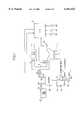
- FIG. 1showing the embodiment, air is drawn into a vehicle internal combustion engine 1 via an intake air passage 3 in which is disposed a throttle valve 2 linked to an accelerator pedal (not shown in the figure).
- An air flow meter 4 for detecting an intake air quantity which is flow controlled by the throttle valve 2,is disposed upstream of the intake air passage 3, and solenoid type fuel injection valves 5 are provided for each cylinder, in a downstream section (manifold section) of the intake air passage 3, for injecting fuel pumped from a fuel pump (not shown in the figure) and controlled to a predetermined pressure by a pressure regulator, into the intake air passage 3.
- Control of the fuel injection quantity from the fuel injection valves 5is performed by a control unit 6 incorporating a microcomputer.
- the engine 1is provided with a fuel vapor treatment unit.
- the fuel vapor treatment unitadsorbs and collects fuel vapor produced in a fuel tank 19, in an absorption material (absorption device) such as activated carbon filled into a canister 21, by way of a fuel vapor introducing passage 20.
- the fuel absorbed in the absorption materialis then supplied to the intake air passage 3 on the downstream side of the throttle valve 2 via a purge passage 22, together with fresh air, using the negative intake pressure of the engine 1.
- PCVpurge control valve
- the following piping systemis constructed.
- an electric pump (air pump) 28is connected to an air introduction port opened at a lower portion of the canister 21, by means of a first passage 25 in which is disposed a reference orifice 24 of a reference aperture diameter, for example 0.5 mm aperture diameter, and a second passage 27 connected in parallel with the first passage 25 by way of one port of a switching valve 26.
- An air introduction passage 29 connected to the intake port of the electric pump 28introduces air via an air filter 30.
- An air discharge passage 31is connected to the other port of the switching valve 26.
- the switching valve 26is switched between a condition where the other port to which the air discharge passage 31 is connected, is communicated with the second passage 27 which leads to the air introduction port of the canister 21, and air discharged from the air discharge passage 31 is discharged to the atmosphere via the air filter 30, and a condition where the second passage 27 is opened via the one port so that the electric pump 28 and the air introduction port of the canister 21 are communicated via the second passage 27.
- a rotational speed sensor 32for detecting an engine rotational speed N
- a water temperature sensor 33for detecting water temperature Tw
- an air-fuel ratio sensor 34for detecting air-fuel ratio based for example on oxygen concentration in the exhaust
- a fuel temperature sensor 35for detecting fuel temperature inside the fuel tank 19. Detection signals from these sensors are output to the control unit 6.
- the control unit 6controls the fuel injection quantity from the fuel injection valves 5, based on signals from the respective sensors, and under predetermined operating conditions, controls to open the purge control valve 23 to effect processing for purging the fuel vapor into the intake system, and under predetermined conditions effects leak diagnosis according to the present invention.
- a fuel vapor leak diagnosis routine carried out by the control unit 6 for such a constructionwill be explained in accordance with the flow chart of FIG. 2.
- step S1it is judged if predetermined leak diagnosis conditions have materialized.
- these leak diagnosis conditionsare preferably when the engine is stopped, and it is diagnosed in a separately executed fault diagnosis routine that the purge control valve 23 is normal.
- step S2scavenge time change device
- the scavenge timeis longer when estimated that the fuel temperature when detected by the fuel temperature sensor 35 (fuel temperature detection device) is higher and hence the amount of fuel vapor generated is large.
- the removal of residual pressure (negative pressure) and residual gas by scavengingcan be reliably effected, and an increase in leak diagnosis time due to scavenging being effected for longer than necessary can be avoided.
- the scavengingcan be carried out several times at intervals. Furthermore, when sufficient time has elapsed since stopping the engine, the outside air temperature or the engine intake air temperature will have a constant correlation with the fuel temperature. Hence the construction may be such that the fuel temperature is estimated from the outside air temperature detected by an outside air temperature sensor or from an intake air temperature detected by an intake air temperature sensor.
- step S2control proceeds to step S3 (scavenge device) to execute actual processing for scavenging the fuel vapor inside the piping.
- the purge control valve 23is opened, the one port of the switching valve 26 is closed, the other port is opened, and the electric pump 28 is driven by applying a constant voltage thereto.
- step S4a basic value DLSLST of the leak diagnosis judgement level is determined. More specifically, the purge control valve 23 is closed, the one port of the switching valve 26 is closed, the other port is opened, and the electric pump 28 is driven, and this condition is maintained for a predetermined time.
- the drive current (drive load) of the electric pump 28is detected, and this current value is set as the basic value DLSLST of the judgement level. That is to say, the drive current (drive load) of the electric pump 28 for when the air passes through the reference orifice 24 of the reference aperture diameter is detected.
- step S5the basic value DLSLST of the judgment level is corrected in accordance with the fuel temperature, to set a final judgment level DLSL judgment level setting device). More specifically, a correction value KTEMP for the judgment level is looked up from a characteristic map as shown in FIG. 6, and the judgment level DLSL then computed from the following equation:
- the correction value KTEMPis set to zero without a practical correction when the fuel temperature is within a predetermined range (for example 0° ⁇ 30° C.), while when the temperature exceeds 30° C., the correction value KTEMP is set to a negative value. Furthermore, at the time of low temperatures less than 0° C., this is set to a positive value. Consequently, at the time of high temperatures above the fuel temperature setting range, the judgment level DLSL is increasingly corrected, while at the time of low temperatures below the setting range, the judgment level DLSL is reducingly corrected.
- a predetermined rangefor example 0° ⁇ 30° C.
- step S6leak diagnosis test is executed. More specifically, the purge control valve 23 is closed, the other port of the switching valve 26 closed and the one port is opened, and the electric pump 28 is driven, and this condition is maintained for a predetermined time.
- step S7the drive current detected in step S6 is compared with the judgment level DLSL computed in step S5, to effect fuel vapor leak diagnosis.
- controlproceeds to S8 thus diagnosing that a leak has occurred, while when judged that the drive current is greater than the judgment level DLSL control proceeds to step S9, thus diagnosing that a leak has not occurred.
- step S7 through step S9corresponds to the leak diagnosis device.
- the drive efficiency of the fuel pumpis reduced, then as mentioned before the correction value KTEMP is used to effect a correction to reduce or increase the judgment level DLSL, thereby avoiding the influence on the leak diagnosis due to these fuel temperatures, and ensuring a high diagnosis accuracy.
- the constructionmay be such that instead of the characteristic map shown in FIG. 6, the correction value KTEMP is looked up from a table as shown in FIG. 7.
Landscapes
- Engineering & Computer Science (AREA)
- Chemical & Material Sciences (AREA)
- Combustion & Propulsion (AREA)
- Mechanical Engineering (AREA)
- General Engineering & Computer Science (AREA)
- Supplying Secondary Fuel Or The Like To Fuel, Air Or Fuel-Air Mixtures (AREA)
Abstract
Description
1. Field of the Invention
The present invention relates to apparatus and method for diagnosing leaks of a fuel vapor treatment unit of a vehicle internal combustion engine, for diagnosing the presence of leaks in piping.
2. Description of the Related Art
With conventional fuel vapor treatment units for vehicle internal combustion engines, the fuel vapor produced in the fuel tank etc. is temporarily adsorbed in a canister. Then under predetermined engine operating conditions, the adsorbed fuel vapor is de-adsorbed and drawn into the engine intake system, thereby preventing evaporation of the fuel vapor into the atmosphere (refer to Japanese Unexamined Patent Publication No. 5-215020).
With the above unit however, if a crack occurs along the piping, or a fault occurs in a seal at a piping connection, then some of the fuel vapor from the leaking portion will evaporate into the atmosphere, so that the original evaporation prevention effect cannot be fully realized.
Therefore, a leak diagnosis apparatus has been disclosed in Japanese Unexamined Patent Publication No. 7-139439 which confines the negative intake pressure of the internal combustion engine inside the piping and then diagnoses the presence of leaks based on a change in pressure in the piping.
However, with an apparatus for diagnosing the presence of leaks in this manner based on a change in pressure, there is the problem that in the case of minute holes in the piping where the amount of leakage is small, it is difficult to diagnose with high accuracy.
The present invention takes into consideration such heretofore problems, with the object of providing apparatus and method for diagnosing leaks of a fuel vapor treatment unit, which can diagnose at a high accuracy even with a small amount of leakage, and which can avoid an influence on leak diagnosis due to fuel temperature, to thereby improve diagnosis accuracy.
Furthermore, it is an object to provide apparatus and method for diagnosing leaks of a fuel vapor treatment unit, which can diagnose at a high accuracy even with a small amount of leakage, and which can infallibly avoid an influence on leak diagnosis due to residual pressure or residual fuel vapor in the piping.
With apparatus and method for diagnosing leaks of a fuel vapor treatment unit according to the present invention for achieving the above objects, the construction is such that the presence of fuel vapor leaks is diagnosed by comparing a drive load of an electric pump for when air is pumped by the electric pump into piping to be leak diagnosed of the fuel vapor treatment unit, with a judgment level,. Moreover, the judgment level is set based on the temperature of fuel.
With such a construction, air is pumped by the electric pump (air pump) into the piping to be leak diagnosed, and the drive load (drive current) of the electric pump at this time is compared with the judgment level set based on the temperature of fuel, to thereby diagnose the presence of fuel vapor leaks. More specifically, when the drive load (drive current) of the electric pump is less than the judgment level, it is diagnosed that a leak has occurred.
In this way, in the case where the drive load of the electric pump increases as a result of an increase in the pressure inside the piping due to fuel vapor from high temperature fuel, the judgment level is corrected corresponding to this, enabling the influence on the leak diagnosis due to fuel temperature to be avoided, ensuring high diagnosis accuracy. Furthermore, in the case where, under a low fuel temperature environment with the temperature of the electric pump also low so that the drive efficiency of the electric pump is reduced, the judgment level is corrected corresponding to this, enabling the influence on the leak diagnosis due to fuel temperature to be avoided, ensuring high diagnosis accuracy.
Here, the construction is preferably such that the drive load of the electric pump is obtained beforehand for when the air pumped by the electric pump leaks via a reference orifice having a reference aperture diameter, and the judgment level is set based on the drive load and fuel temperature.
With such a construction, the air pumped by the electric pump is discharged to the atmosphere via a reference orifice of an aperture diameter corresponding to a leak area which becomes the reference, to thereby obtain the drive load of the electric pump for the reference leak area. The judgment level to be used for the actual leak diagnosis can then be set with this as the reference. Furthermore, by adding to the judgment level a correction corresponding to the fuel temperature, then the influence on leak diagnosis due to fuel temperature can be avoided.
Moreover, the construction may involve estimating the fuel temperature to be used in setting the judgment level, from the outside air temperature, or from detection results of intake air temperature of the internal combustion engine.
With such a construction, for example, the fuel temperature can be estimated by appropriating an outside air temperature sensor provided for temperature adjustment of the vehicle air-conditioning, or by appropriating an intake air temperature sensor provided for correcting fuel injection quantity.
Preferably the construction involves scavenging, prior to leak diagnosis, by feeding air using the electric pump into the piping to be leak diagnosed of the fuel vapor treatment unit.
With such a construction, since prior to leak diagnosis the piping to be leak diagnosed is scavenged, then residual pressure and residual gas which can influence the pressure condition inside the piping are removed beforehand, enabling diagnosis to be accurately effected by the drive load of the electric pump.
Here the construction preferably involves changing the time of the scavenging, corresponding to the temperature of the fuel.
With such a construction, prior to leak diagnosis, scavenging is effected to remove residual pressure and residual gas. However the time of the scavenging is changed depending on fuel temperature which is correlated with the residual gas quantity, so that scavenging is carried out for only just enough time to remove the residual pressure and residual gas.
Moreover, with the apparatus and method for diagnosing leaks of a fuel vapor treatment unit according to the present invention for achieving the above objects, the construction includes, scavenging for a scavenge time corresponding to the temperature of the fuel, by feeding air using an electric pump into the piping to be leak diagnosed of the fuel vapor treatment unit, and after completion of the scavenging, obtaining the drive load of the electric pump for when the air is pumped to inside the piping by the electric pump, and comparing the drive load with a judgment level, to thereby diagnose the presence of fuel vapor leaks.
With such a construction, when the air is pumped to inside the piping by the electric pump, if there is a leak, then the drive load of the electric pump is reduced. Hence the presence of leaks can be diagnosed by the magnitude of the drive load. Here, prior to leak diagnosis, scavenging is effected to remove residual pressure and residual gas. However the time of the scavenging is changed depending on fuel temperature which is correlated with the residual gas quantity, so that scavenging is carried out for only just enough time to remove the residual pressure and residual gas
Here, the construction preferably involves obtaining beforehand the drive load of the electric pump for when the air pumped by the electric pump leaks via a reference orifice having a reference aperture diameter, and setting the judgment level based on the drive load.
With such a construction, the air pumped by the electric pump is discharged to the atmosphere via a reference orifice of an aperture diameter corresponding to a leak area which becomes the reference, to thereby obtain the drive load of the electric pump for the reference leak area. The judgment level to be used for the actual leak diagnosis can then be set with this as the reference.
Moreover, the construction may involve estimating the fuel temperature to be used in setting the scavenge time, from the outside air temperature, or from detection results of intake air temperature of the internal combustion engine.
With such a construction, for example, the fuel temperature can be estimated by appropriating an outside air temperature sensor provided for temperature adjustment of the vehicle air-conditioning, or by appropriating an intake air temperature sensor provided for correcting fuel injection quantity.
Other objects, and aspects of the present invention will become apparent from the following description of embodiments given in conjunction with the appended drawings.
FIG. 1 is a diagram showing the system structure of an embodiment of the present invention;
FIG. 2 is a flow chart showing a leak diagnosis routine of the embodiment;
FIG. 3 is a diagram showing the flow of air at the time of scavenging, in the embodiment;
FIG. 4 is a diagram showing the flow of air at the time of setting a judgment level, in the embodiment;
FIG. 5 is a diagram showing the flow of air at the time of executing leak diagnosis test in the embodiment;
FIG. 6 is a characteristic map showing a relation between fuel temperature and correction value KTEMP, used in the embodiment; and
FIG. 7 is a characteristic map showing a relation between fuel temperature and correction value KTEMP, used in another embodiment.
As follows is a description of an embodiment of the present invention.
In FIG. 1 showing the embodiment, air is drawn into a vehicle internal combustion engine 1 via anintake air passage 3 in which is disposed athrottle valve 2 linked to an accelerator pedal (not shown in the figure).
An air flow meter 4 for detecting an intake air quantity which is flow controlled by thethrottle valve 2, is disposed upstream of theintake air passage 3, and solenoid typefuel injection valves 5 are provided for each cylinder, in a downstream section (manifold section) of theintake air passage 3, for injecting fuel pumped from a fuel pump (not shown in the figure) and controlled to a predetermined pressure by a pressure regulator, into theintake air passage 3. Control of the fuel injection quantity from thefuel injection valves 5 is performed by acontrol unit 6 incorporating a microcomputer.
Furthermore, the engine 1 is provided with a fuel vapor treatment unit. The fuel vapor treatment unit adsorbs and collects fuel vapor produced in afuel tank 19, in an absorption material (absorption device) such as activated carbon filled into acanister 21, by way of a fuelvapor introducing passage 20. The fuel absorbed in the absorption material is then supplied to theintake air passage 3 on the downstream side of thethrottle valve 2 via apurge passage 22, together with fresh air, using the negative intake pressure of the engine 1.
In thepurge passage 22 is disposed a solenoid operated purge control valve (PCV) 23 which is controlled based on a control signal from thecontrol unit 6.
For leak diagnosis of the fuel vapor in the fuel vapor treatment unit, the following piping system is constructed.
That is to say, an electric pump (air pump) 28 is connected to an air introduction port opened at a lower portion of thecanister 21, by means of afirst passage 25 in which is disposed areference orifice 24 of a reference aperture diameter, for example 0.5 mm aperture diameter, and asecond passage 27 connected in parallel with thefirst passage 25 by way of one port of aswitching valve 26. Anair introduction passage 29 connected to the intake port of theelectric pump 28 introduces air via anair filter 30. Anair discharge passage 31 is connected to the other port of theswitching valve 26.
Theswitching valve 26 is switched between a condition where the other port to which theair discharge passage 31 is connected, is communicated with thesecond passage 27 which leads to the air introduction port of thecanister 21, and air discharged from theair discharge passage 31 is discharged to the atmosphere via theair filter 30, and a condition where thesecond passage 27 is opened via the one port so that theelectric pump 28 and the air introduction port of thecanister 21 are communicated via thesecond passage 27.
Moreover, there is provided arotational speed sensor 32 for detecting an engine rotational speed N, awater temperature sensor 33 for detecting water temperature Tw, an air-fuel ratio sensor 34 for detecting air-fuel ratio based for example on oxygen concentration in the exhaust, and afuel temperature sensor 35 for detecting fuel temperature inside thefuel tank 19. Detection signals from these sensors are output to thecontrol unit 6.
Thecontrol unit 6 controls the fuel injection quantity from thefuel injection valves 5, based on signals from the respective sensors, and under predetermined operating conditions, controls to open thepurge control valve 23 to effect processing for purging the fuel vapor into the intake system, and under predetermined conditions effects leak diagnosis according to the present invention.
A fuel vapor leak diagnosis routine carried out by thecontrol unit 6 for such a construction will be explained in accordance with the flow chart of FIG. 2.
In step S1, it is judged if predetermined leak diagnosis conditions have materialized. Here these leak diagnosis conditions are preferably when the engine is stopped, and it is diagnosed in a separately executed fault diagnosis routine that thepurge control valve 23 is normal.
When judged in step S1 that the leak diagnosis conditions have materialized, control proceeds to step S2 (scavenge time change device) to set the time (scavenge time) for executing processing for scavenging the fuel vapor inside the piping.
The scavenge time, as shown in FIG. 2, is longer when estimated that the fuel temperature when detected by the fuel temperature sensor 35 (fuel temperature detection device) is higher and hence the amount of fuel vapor generated is large. As a result, the removal of residual pressure (negative pressure) and residual gas by scavenging can be reliably effected, and an increase in leak diagnosis time due to scavenging being effected for longer than necessary can be avoided.
When the fuel temperature is high, the scavenging can be carried out several times at intervals. Furthermore, when sufficient time has elapsed since stopping the engine, the outside air temperature or the engine intake air temperature will have a constant correlation with the fuel temperature. Hence the construction may be such that the fuel temperature is estimated from the outside air temperature detected by an outside air temperature sensor or from an intake air temperature detected by an intake air temperature sensor.
Once the scavenge time has been set in step S2, control proceeds to step S3 (scavenge device) to execute actual processing for scavenging the fuel vapor inside the piping.
More specifically, thepurge control valve 23 is opened, the one port of the switchingvalve 26 is closed, the other port is opened, and theelectric pump 28 is driven by applying a constant voltage thereto.
At this time, as shown in FIG. 3, due to operation of theelectric pump 28, air introduced via theair filter 30 and theair introduction passage 29 passes via thefirst passage 25 through thecanister 21 and is discharged into theintake air passage 3 via thepurge passage 22. Furthermore, a part of the air passes from the switchingvalve 26 via theair discharge passage 31 and theair filter 30 and is discharged into the atmosphere. As a result, the residual pressure (negative pressure) and residual gas inside thepurge passage 22 is scavenged and thus eliminated.
Then in step S4, a basic value DLSLST of the leak diagnosis judgement level is determined. More specifically, thepurge control valve 23 is closed, the one port of the switchingvalve 26 is closed, the other port is opened, and theelectric pump 28 is driven, and this condition is maintained for a predetermined time.
At this time, as shown in FIG. 4, due to operation of theelectric pump 28, air introduced via theair filter 30 and theair introduction passage 29, passes via thefirst passage 25 and is discharged to the atmosphere from the switchingvalve 26 via theair discharge passage 31 and theair filter 30.
Under these conditions, the drive current (drive load) of theelectric pump 28 is detected, and this current value is set as the basic value DLSLST of the judgement level. That is to say, the drive current (drive load) of theelectric pump 28 for when the air passes through thereference orifice 24 of the reference aperture diameter is detected.
Then, in step S5, the basic value DLSLST of the judgment level is corrected in accordance with the fuel temperature, to set a final judgment level DLSL judgment level setting device). More specifically, a correction value KTEMP for the judgment level is looked up from a characteristic map as shown in FIG. 6, and the judgment level DLSL then computed from the following equation:
DLSL=DLSLST-KTEMP
Here, the correction value KTEMP is set to zero without a practical correction when the fuel temperature is within a predetermined range (for example 0° ˜30° C.), while when the temperature exceeds 30° C., the correction value KTEMP is set to a negative value. Furthermore, at the time of low temperatures less than 0° C., this is set to a positive value. Consequently, at the time of high temperatures above the fuel temperature setting range, the judgment level DLSL is increasingly corrected, while at the time of low temperatures below the setting range, the judgment level DLSL is reducingly corrected.
In step S6, leak diagnosis test is executed. More specifically, thepurge control valve 23 is closed, the other port of the switchingvalve 26 closed and the one port is opened, and theelectric pump 28 is driven, and this condition is maintained for a predetermined time.
At this time, as shown in FIG. 5, due to operation of theelectric pump 28, air introduced via theair filter 30 and theair introduction passage 29 passes via thesecond passage 27 through thecanister 21 and flows into the fuelvapor introduction passage 20 and thepurge passage 22 reaching from thefuel tank 19 to thepurge control valve 23.
Under this condition, the drive current for theelectric pump 28 is detected.
In step S7, the drive current detected in step S6 is compared with the judgment level DLSL computed in step S5, to effect fuel vapor leak diagnosis.
That is to say, when judged that the drive current is equal to or below the judgment level, control proceeds to S8 thus diagnosing that a leak has occurred, while when judged that the drive current is greater than the judgment level DLSL control proceeds to step S9, thus diagnosing that a leak has not occurred.
The sections of step S7 through step S9 corresponds to the leak diagnosis device.
In this way, basically, in the case where the drive current of theelectric pump 28 at the time of leak diagnosis testing is smaller than the drive current required to pass the air through thereference orifice 24 having the reference aperture diameter, that is to say in the case where the drive current of theelectric pump 28 is reduced, it is diagnosed that a crack equivalent to the opening up of a hole larger then the reference aperture diameter has occurred in the fuelvapor introduction passage 20, or thepurge passage 22, producing a leak greater than a set level, while in other cases, it is diagnosed that there is no leak (normal).
Here, in the case where the drive current increases due to high fuel temperature and hence an increase in fuel vapor pressure, or in the case where under a low fuel temperature environment where the electric pump temperature is also low, the drive efficiency of the fuel pump is reduced, then as mentioned before the correction value KTEMP is used to effect a correction to reduce or increase the judgment level DLSL, thereby avoiding the influence on the leak diagnosis due to these fuel temperatures, and ensuring a high diagnosis accuracy.
The construction may be such that instead of the characteristic map shown in FIG. 6, the correction value KTEMP is looked up from a table as shown in FIG. 7.
Claims (19)
1. A leak diagnosis apparatus for a fuel vapor treatment unit where fuel vapor produced in a fuel tank is collected by adsorbing into an adsorption means, and the fuel vapor collected in the adsorption means is purged under predetermined engine operating conditions and supplied to an engine, said leak diagnosis apparatus comprising:
leak diagnosis means for diagnosing the presence of fuel vapor leaks by comparing a drive load of an electric pump for when air is pumped by said electric pump into a system of fuel piping of said fuel vapor treatment unit to be leak diagnosed, with a set judgement level of drive load threshold, wherein the set iudgement level is higher for higher fuel temperatures,
fuel temperature detection means for detecting the temperature of fuel, wherein a fuel vapor leak is deemed to exist when the comparisons show that the drive load of the electric pump is less than the set judgement level, and
judgement level setting means for setting said judgment level based on the detected temperature.
2. A leak diagnosis apparatus for a fuel vapor treatment unit according to claim 1, wherein said judgment level setting means:
detects the drive load of said electric pump at a reference leak condition for when the air pumped by said electric pump leaks via a reference orifice having a reference aperture diameter, and
sets said judgment level based on said drive load and said detected temperature of the fuel.
3. A leak diagnosis apparatus for a fuel vapor treatment unit according to claim 1, wherein said fuel temperature detection means estimates the fuel temperature by detecting an outside air temperature, or an intake temperature of the internal combustion engine.
4. A leak diagnosis apparatus for a fuel vapor treatment unit according to claim 1, further comprising scavenging means for scavenging prior to leak diagnosis with said leak diagnosis means, by feeding air using said electric pump into the piping to be leak diagnosed.
5. A leak diagnosis apparatus for fuel vapor treatment unit according to claim 4, further comprising scavenge time change means for changing the time of scavenging by said scavenging means, corresponding to the temperature of the fuel detected by said fuel temperature detection.
6. A leak diagnosis apparatus for a fuel vapor treatment unit where fuel vapor produced in a fuel tank is collected by adsorbing into an adsorption means, and the fuel vapor collected in the adsorption means is purged under predetermined engine operating conditions and supplied to an engine, said leak diagnosis apparatus comprising:
leak diagnosis means for diagnosing the presence of fuel vapor leaks by comparing a drive load of an electric pump for when air is pumped by said electric pump into a system of fuel piping to be leak diagnosed of said fuel vapor treatment unit, with a judgement level,
scavenging means for scavenging prior to leak diagnosis with said leak diagnosis means, by feeding air using said electric pump into the piping to be leak diagnosed of said fuel vapor treatment unit,
fuel temperature detection means for detecting the temperature of fuel, wherein a fuel vapor leak is deemed to exist when the comparisons show that the drive load of the electric pump is less than the set judgement level,
scavenge time change means for changing a time of scavenging by said scavenging means, corresponding to the temperature of the fuel detected by said fuel temperature detection means, and
judgment level setting means for setting said judgment level based on the temperature of the fuel.
7. A leak diagnosis apparatus for a fuel vapor treatment unit according to claim 6, wherein said judgment level setting means detects the drive load of said electric pump at a reference leak condition for when the air pumped by said electric pump leaks via a reference orifice having a reference aperture diameter, and sets said judgment level based on said drive load.
8. A leak diagnosis apparatus for a fuel vapor treatment unit according to claim 6, wherein said fuel temperature detection means estimates the fuel temperature by detecting an outside air temperature, or an intake temperature of the internal combustion engine.
9. A leak diagnosis method for a fuel vapor treatment unit where fuel vapor produced in a fuel tank is collected by adsorbing into an adsorption means, and the fuel vapor collected in the adsorption means is purged under predetermined engine operating conditions and supplied to an engine, comprising:
detecting a drive load of an electric pump for when air is pumped by said electric pump into a system of fuel piping to be leak diagnosed of said fuel vapor treatment unit, and
comparing said drive load with a judgment level set based on said drive load and the temperature of fuel, to thereby diagnose the presence of leaks of fuel vapor, wherein said set judgement level of the drive load threshold is higher for higher fuel temperatures, and wherein a fuel vapor leak is deemed to exist when the comparisons show that the drive load of said electric pump is less than said set judgement level.
10. A leak diagnosis method for a fuel vapor treatment unit according to claim 9, further comprising:
detecting the drive load of said electric pump at a reference leak condition for when the air pumped by said electric pump leaks via a reference orifice having a reference aperture diameter, and
setting said judgment level based on said drive load and said detected temperature of the fuel.
11. A leak diagnosis method for a fuel vapor treatment unit according to claim 9, further comprising:
setting the fuel temperature by detecting an outside air temperature, an intake temperature of the internal combustion engine.
12. A leak diagnosis method for a fuel vapor treatment unit according to claim 9, further comprising:
performing scavenging prior to leak diagnosis, by feeding air using said electric pump into the piping to be leak diagnosed.
13. A leak diagnosis method for a fuel vapor treatment unit according to claim 12, further comprising:
changing the time of said scavenging corresponding to the temperature of the fuel, wherein the time of scavenging is set longer when the fuel temperature is higher.
14. A leak diagnosis method for a fuel vapor treatment unit where fuel vapor produced in a fuel tank is collected by adsorbing into an adsorption means, and the fuel vapor collected in the adsorption means is purged under predetermined engine operating conditions and supplied to an engine, comprising:
performing scavenging for a scavenge time corresponding to a temperature of the fuel, by feeding air using an electric pump into a system of fuel piping of said fuel vapor treatment unit to be leak diagnosed,
after completion of said scavenging, detecting the drive load of said electric pump for when the air is pumped to inside the piping by said electric pump, and
comparing said drive load with a judgment level, to thereby diagnose the presence of fuel vapor leaks.
15. A leak diagnosis method for a fuel vapor treatment unit according to claim 14, further comprising:
detecting a drive load of said electric pump at a reference leak condition for when the air pumped by said electric pump leaks via a reference orifice having a reference orifice having a reference diameter, and
setting said judgment level based on said drive current.
16. A leak diagnosis method for a fuel vapor treatment unit according to claim 14, further comprising:
estimating the fuel temperature from an outside air temperature, or an intake temperature of the internal combustion engine.
17. The leak diagnosis apparatus according to claim 5, wherein the time of scavenging is set longer when the fuel temperature is higher.
18. The leak diagnosis apparatus according to claim 6, wherein the time of scavenging is set longer when the fuel temperature is higher.
19. A leak diagnosis method for a fuel vapor treatment unit according to claim 14, wherein the time of scavenging is set longer when the fuel temperature is higher.
Applications Claiming Priority (4)
| Application Number | Priority Date | Filing Date | Title |
|---|---|---|---|
| JP07152998AJP3340380B2 (en) | 1998-03-20 | 1998-03-20 | Leak diagnosis device for evaporative fuel treatment equipment |
| JP10-071529 | 1998-03-20 | ||
| JP16205598AJP3326113B2 (en) | 1998-06-10 | 1998-06-10 | Leak diagnosis device for evaporative fuel treatment equipment |
| JP10-162055 | 1998-06-10 |
Publications (1)
| Publication Number | Publication Date |
|---|---|
| US6161423Atrue US6161423A (en) | 2000-12-19 |
Family
ID=26412628
Family Applications (1)
| Application Number | Title | Priority Date | Filing Date |
|---|---|---|---|
| US09/268,667Expired - LifetimeUS6161423A (en) | 1998-03-20 | 1999-03-16 | Apparatus and method for diagnosing leaks of fuel vapor treatment unit |
Country Status (1)
| Country | Link |
|---|---|
| US (1) | US6161423A (en) |
Cited By (23)
| Publication number | Priority date | Publication date | Assignee | Title |
|---|---|---|---|---|
| US6389882B1 (en)* | 1999-06-30 | 2002-05-21 | Unisia Jecs Corporation | Apparatus and method for diagnosing leakage in fuel vapor treatment apparatus |
| US20020139173A1 (en)* | 2001-04-03 | 2002-10-03 | Masao Kano | Leak check apparatus for fuel vapor purge system |
| US6550315B2 (en)* | 2000-04-13 | 2003-04-22 | Robert Bosch Gmbh | Method and arrangement for checking the tightness of a vessel |
| US6615808B2 (en)* | 2000-02-11 | 2003-09-09 | Robert Bosch Gmbh | Method for checking the tightness of an automotive tank system |
| US6644100B2 (en)* | 2000-04-06 | 2003-11-11 | Robert Bosch Gmbh | Method for conducting a leak test of a tank ventilation system of a vehicle |
| US20040000187A1 (en)* | 2002-06-28 | 2004-01-01 | Mitsuyuki Kobayashi | Evaporative emission leak detection system with brushless motor |
| US20040149016A1 (en)* | 2003-01-29 | 2004-08-05 | Denso Corporation | Leak check device for evaporated fuel purging system |
| US20040173013A1 (en)* | 2003-03-04 | 2004-09-09 | Denso Corporation | Leak check device for evaporated fuel purge system |
| US20060005620A1 (en)* | 2002-03-20 | 2006-01-12 | Atsushi Koike | Flow rate measuring method and flowmeter, flow rate measuring section package used for them and flow rate measuring unit using them, and piping leakage inspection device using flowmeter |
| US20060150722A1 (en)* | 2005-01-12 | 2006-07-13 | Denso Corporation | Leak detector for evaporated fuel |
| US20070189907A1 (en)* | 2006-02-16 | 2007-08-16 | Denso Corporation | Pump apparatus, system having the same, and method for operating the same |
| US20090293599A1 (en)* | 2008-06-03 | 2009-12-03 | Gm Global Technology Operations, Inc. | Wind condition based vapor leak detection test |
| US20110127284A1 (en)* | 2009-11-30 | 2011-06-02 | Ford Global Technologies, Llc | Fuel tank |
| US20120145133A1 (en)* | 2010-12-14 | 2012-06-14 | Toyota Jidosha Kabushiki Kaisha | Fuel vapor processing systems |
| CN103282637A (en)* | 2010-12-28 | 2013-09-04 | 罗伯特·博世有限公司 | Device for selectively regenerating or performing tank leakage diagnosis of a tank ventilation system |
| US20140026867A1 (en)* | 2012-07-25 | 2014-01-30 | Denso Corporation | Fuel vapor purge device |
| US20160252032A1 (en)* | 2013-10-14 | 2016-09-01 | Continental Automotive Gmbh | Method and Device for Operating a Fuel Pump |
| US20200003162A1 (en)* | 2017-02-07 | 2020-01-02 | Aisan Kogyo Kabushiki Kaisha | Pump module, evaporated fuel processing device provided with pump module, and pump control circuit |
| US10711735B2 (en)* | 2018-05-09 | 2020-07-14 | Eagle Actuator Components Gmbh & Co. Kg | Arrangement for regenerating an activated carbon filter |
| CN111720242A (en)* | 2020-07-15 | 2020-09-29 | 武汉飞恩微电子有限公司 | On-line leak diagnosis device and method for fuel vapor blowing system |
| US10941718B2 (en)* | 2018-11-21 | 2021-03-09 | Aisan Kogyo Kabushiki Kaisha | Evaporated fuel processing apparatus |
| US10995686B2 (en) | 2017-02-28 | 2021-05-04 | Aisan Kogyo Kabushiki Kaisha | Evaporated fuel treatment device |
| US11060486B2 (en) | 2018-07-20 | 2021-07-13 | Volkswagen Aktiengesellschaft | Internal combustion engine with a venturi nozzle disposed in a fluid-carrying component in fluid connection with a tank ventilation line |
Citations (12)
| Publication number | Priority date | Publication date | Assignee | Title |
|---|---|---|---|---|
| JPH05215020A (en)* | 1991-12-09 | 1993-08-24 | Honda Motor Co Ltd | Canister purge controller |
| US5408866A (en)* | 1992-11-25 | 1995-04-25 | Nissan Motor Co., Ltd. | Leak diagnosis system for evaporative emission control system |
| US5467641A (en)* | 1993-02-13 | 1995-11-21 | Lucas Industries Public Limited Company | Method of and apparatus for detecting fuel system leak |
| US5606121A (en)* | 1996-03-05 | 1997-02-25 | Chrysler Corporation | Method of testing an evaporative emission control system |
| US5726354A (en)* | 1995-07-31 | 1998-03-10 | Toyota Jidosha Kabushiki Kaisha | Testing method for fuel vapor treating apparatus |
| US5739421A (en)* | 1995-12-08 | 1998-04-14 | Nissan Motor Co.Ltd. | Leak diagnosis system for evaporative emission control system |
| US5750888A (en)* | 1995-07-21 | 1998-05-12 | Mitsubishi Jidosha Kogyo Kabushi Kaisha | Fault diagnostic method and apparatus for fuel evaporative emission control system |
| US5767395A (en)* | 1995-07-14 | 1998-06-16 | Nissan Motor Co., Ltd. | Function diagnosis apparatus for evaporative emission control system |
| US5786531A (en)* | 1997-02-27 | 1998-07-28 | General Motors Corporation | Compression ratio measurement |
| US5817925A (en)* | 1997-03-26 | 1998-10-06 | Siemens Electric Limited | Evaporative emission leak detection system |
| US5898108A (en)* | 1995-01-06 | 1999-04-27 | Snap-On Technologies, Inc. | Evaporative emission tester |
| US5941927A (en)* | 1997-09-17 | 1999-08-24 | Robert Bosch Gmbh | Method and apparatus for determining the gas temperature in an internal combustion engine |
- 1999
- 1999-03-16USUS09/268,667patent/US6161423A/ennot_activeExpired - Lifetime
Patent Citations (12)
| Publication number | Priority date | Publication date | Assignee | Title |
|---|---|---|---|---|
| JPH05215020A (en)* | 1991-12-09 | 1993-08-24 | Honda Motor Co Ltd | Canister purge controller |
| US5408866A (en)* | 1992-11-25 | 1995-04-25 | Nissan Motor Co., Ltd. | Leak diagnosis system for evaporative emission control system |
| US5467641A (en)* | 1993-02-13 | 1995-11-21 | Lucas Industries Public Limited Company | Method of and apparatus for detecting fuel system leak |
| US5898108A (en)* | 1995-01-06 | 1999-04-27 | Snap-On Technologies, Inc. | Evaporative emission tester |
| US5767395A (en)* | 1995-07-14 | 1998-06-16 | Nissan Motor Co., Ltd. | Function diagnosis apparatus for evaporative emission control system |
| US5750888A (en)* | 1995-07-21 | 1998-05-12 | Mitsubishi Jidosha Kogyo Kabushi Kaisha | Fault diagnostic method and apparatus for fuel evaporative emission control system |
| US5726354A (en)* | 1995-07-31 | 1998-03-10 | Toyota Jidosha Kabushiki Kaisha | Testing method for fuel vapor treating apparatus |
| US5739421A (en)* | 1995-12-08 | 1998-04-14 | Nissan Motor Co.Ltd. | Leak diagnosis system for evaporative emission control system |
| US5606121A (en)* | 1996-03-05 | 1997-02-25 | Chrysler Corporation | Method of testing an evaporative emission control system |
| US5786531A (en)* | 1997-02-27 | 1998-07-28 | General Motors Corporation | Compression ratio measurement |
| US5817925A (en)* | 1997-03-26 | 1998-10-06 | Siemens Electric Limited | Evaporative emission leak detection system |
| US5941927A (en)* | 1997-09-17 | 1999-08-24 | Robert Bosch Gmbh | Method and apparatus for determining the gas temperature in an internal combustion engine |
Cited By (37)
| Publication number | Priority date | Publication date | Assignee | Title |
|---|---|---|---|---|
| US6389882B1 (en)* | 1999-06-30 | 2002-05-21 | Unisia Jecs Corporation | Apparatus and method for diagnosing leakage in fuel vapor treatment apparatus |
| US6615808B2 (en)* | 2000-02-11 | 2003-09-09 | Robert Bosch Gmbh | Method for checking the tightness of an automotive tank system |
| US6644100B2 (en)* | 2000-04-06 | 2003-11-11 | Robert Bosch Gmbh | Method for conducting a leak test of a tank ventilation system of a vehicle |
| US6550315B2 (en)* | 2000-04-13 | 2003-04-22 | Robert Bosch Gmbh | Method and arrangement for checking the tightness of a vessel |
| US20020139173A1 (en)* | 2001-04-03 | 2002-10-03 | Masao Kano | Leak check apparatus for fuel vapor purge system |
| US6604407B2 (en)* | 2001-04-03 | 2003-08-12 | Denso Corporation | Leak check apparatus for fuel vapor purge system |
| US7028533B2 (en)* | 2002-03-20 | 2006-04-18 | Mitsui Mining & Smelting Co., Ltd. | Flow rate measuring method and flowmeter, flow rate measuring section package used for them and flow rate measuring unit using them, and piping leakage inspection device using flowmeter |
| US20060005620A1 (en)* | 2002-03-20 | 2006-01-12 | Atsushi Koike | Flow rate measuring method and flowmeter, flow rate measuring section package used for them and flow rate measuring unit using them, and piping leakage inspection device using flowmeter |
| US20040000187A1 (en)* | 2002-06-28 | 2004-01-01 | Mitsuyuki Kobayashi | Evaporative emission leak detection system with brushless motor |
| US20040149016A1 (en)* | 2003-01-29 | 2004-08-05 | Denso Corporation | Leak check device for evaporated fuel purging system |
| US6993957B2 (en)* | 2003-01-29 | 2006-02-07 | Denso Corporation | Leak check device for evaporated fuel purging system |
| US20040173013A1 (en)* | 2003-03-04 | 2004-09-09 | Denso Corporation | Leak check device for evaporated fuel purge system |
| US6964193B2 (en)* | 2003-03-04 | 2005-11-15 | Denso Corporation | Leak check device for evaporated fuel purge system |
| US20060150722A1 (en)* | 2005-01-12 | 2006-07-13 | Denso Corporation | Leak detector for evaporated fuel |
| US7231813B2 (en)* | 2005-01-12 | 2007-06-19 | Denso Corporation | Leak detector for evaporated fuel |
| US20070214871A1 (en)* | 2005-01-12 | 2007-09-20 | Denso Corporation | Leak detector for evaporated fuel |
| US7360401B2 (en) | 2005-01-12 | 2008-04-22 | Denso Corporation | Leak detector for evaporated fuel |
| US20070189907A1 (en)* | 2006-02-16 | 2007-08-16 | Denso Corporation | Pump apparatus, system having the same, and method for operating the same |
| US20090293599A1 (en)* | 2008-06-03 | 2009-12-03 | Gm Global Technology Operations, Inc. | Wind condition based vapor leak detection test |
| US8181507B2 (en)* | 2008-06-03 | 2012-05-22 | GM Global Technology Operations LLC | Wind condition based vapor leak detection test |
| US20110127284A1 (en)* | 2009-11-30 | 2011-06-02 | Ford Global Technologies, Llc | Fuel tank |
| US8602003B2 (en)* | 2009-11-30 | 2013-12-10 | Ford Global Technologies, Llc | Fuel tank |
| US9181906B2 (en)* | 2010-12-14 | 2015-11-10 | Aisan Kogyo Kabushiki Kaisha | Fuel vapor processing systems |
| US20120145133A1 (en)* | 2010-12-14 | 2012-06-14 | Toyota Jidosha Kabushiki Kaisha | Fuel vapor processing systems |
| CN103282637B (en)* | 2010-12-28 | 2016-06-01 | 罗伯特·博世有限公司 | It is alternatively used for the regeneration of box ventilation system or performs the device of case leak diagnostics |
| CN103282637A (en)* | 2010-12-28 | 2013-09-04 | 罗伯特·博世有限公司 | Device for selectively regenerating or performing tank leakage diagnosis of a tank ventilation system |
| US9097216B2 (en)* | 2012-07-25 | 2015-08-04 | Denso Corporation | Fuel vapor purge device |
| US20140026867A1 (en)* | 2012-07-25 | 2014-01-30 | Denso Corporation | Fuel vapor purge device |
| US20160252032A1 (en)* | 2013-10-14 | 2016-09-01 | Continental Automotive Gmbh | Method and Device for Operating a Fuel Pump |
| US10443534B2 (en)* | 2013-10-14 | 2019-10-15 | Continental Automotive Gmbh | Method and device for operating a fuel pump |
| US20200003162A1 (en)* | 2017-02-07 | 2020-01-02 | Aisan Kogyo Kabushiki Kaisha | Pump module, evaporated fuel processing device provided with pump module, and pump control circuit |
| US11035322B2 (en)* | 2017-02-07 | 2021-06-15 | Aisan Kogyo Kabushiki Kaisha | Pump module, evaporated fuel processing device provided with pump module, and pump control circuit |
| US10995686B2 (en) | 2017-02-28 | 2021-05-04 | Aisan Kogyo Kabushiki Kaisha | Evaporated fuel treatment device |
| US10711735B2 (en)* | 2018-05-09 | 2020-07-14 | Eagle Actuator Components Gmbh & Co. Kg | Arrangement for regenerating an activated carbon filter |
| US11060486B2 (en) | 2018-07-20 | 2021-07-13 | Volkswagen Aktiengesellschaft | Internal combustion engine with a venturi nozzle disposed in a fluid-carrying component in fluid connection with a tank ventilation line |
| US10941718B2 (en)* | 2018-11-21 | 2021-03-09 | Aisan Kogyo Kabushiki Kaisha | Evaporated fuel processing apparatus |
| CN111720242A (en)* | 2020-07-15 | 2020-09-29 | 武汉飞恩微电子有限公司 | On-line leak diagnosis device and method for fuel vapor blowing system |
Similar Documents
| Publication | Publication Date | Title |
|---|---|---|
| US6161423A (en) | Apparatus and method for diagnosing leaks of fuel vapor treatment unit | |
| US6220229B1 (en) | Apparatus for detecting evaporative emission control system leak | |
| US7383826B2 (en) | Fuel vapor treatment apparatus, system having the same, method for operating the same | |
| JP3516599B2 (en) | Leak diagnosis device for evaporative fuel treatment equipment | |
| JPH0932658A (en) | Function diagnostic device for evaporative purge system of internal combustion engine | |
| JP3500816B2 (en) | Leak diagnosis device in engine fuel vapor treatment system | |
| US6321728B1 (en) | Apparatus and method for diagnosing faults of fuel vapor treatment unit | |
| US6119663A (en) | Method and apparatus for diagnosing leakage of fuel vapor treatment unit | |
| US6487892B1 (en) | Fault detection apparatus and method for fuel vapor purge system | |
| US6637416B2 (en) | Diagnosis apparatus for detecting abnormal state of evaporation gas purge system | |
| JP3326113B2 (en) | Leak diagnosis device for evaporative fuel treatment equipment | |
| JP3412678B2 (en) | Leak diagnosis device for evaporative fuel treatment equipment | |
| JPH06235355A (en) | Failure diagnosis device for evaporation fuel evaporation prevention device of internal combustion engine | |
| JP3412683B2 (en) | Leak diagnosis device for evaporative fuel treatment equipment | |
| JP2934999B2 (en) | Leak diagnosis device in engine fuel vapor treatment system | |
| JPH05180098A (en) | Diagnostic device for vaporized fuel control system of vehicle | |
| JP3340380B2 (en) | Leak diagnosis device for evaporative fuel treatment equipment | |
| JP3326111B2 (en) | Leak diagnosis device for evaporative fuel treatment equipment | |
| JP3823011B2 (en) | Evaporative fuel treatment device leak diagnosis device | |
| JP3044995B2 (en) | Diagnosis device for fuel evaporative gas suppression device | |
| JP2001152975A (en) | Leak diagnosis device for evaporative fuel treatment equipment | |
| JP2751763B2 (en) | Failure diagnosis device for evaporation purge system | |
| JP3552670B2 (en) | Abnormality diagnosis method and abnormality diagnosis apparatus for evaporative fuel purge device | |
| JP3548026B2 (en) | Leak diagnosis device for evaporative fuel treatment equipment | |
| JP3139188B2 (en) | Failure diagnosis device for evaporative fuel control device |
Legal Events
| Date | Code | Title | Description |
|---|---|---|---|
| AS | Assignment | Owner name:UNISIA JECS CORPORATION, JAPAN Free format text:ASSIGNMENT OF ASSIGNORS INTEREST;ASSIGNOR:OKUMA, SHIGEO;REEL/FRAME:009953/0214 Effective date:19990424 | |
| STCF | Information on status: patent grant | Free format text:PATENTED CASE | |
| FEPP | Fee payment procedure | Free format text:PAYOR NUMBER ASSIGNED (ORIGINAL EVENT CODE: ASPN); ENTITY STATUS OF PATENT OWNER: LARGE ENTITY | |
| FPAY | Fee payment | Year of fee payment:4 | |
| AS | Assignment | Owner name:HITACHI, LTD., JAPAN Free format text:MERGER;ASSIGNOR:HITACHI UNISIA AUTOMOTIVE, LTD.;REEL/FRAME:016263/0073 Effective date:20040927 | |
| FPAY | Fee payment | Year of fee payment:8 | |
| FPAY | Fee payment | Year of fee payment:12 |