US6161271A - Method for mounting a slider mechanism to recloseable flexible packaging - Google Patents
Method for mounting a slider mechanism to recloseable flexible packagingDownload PDFInfo
- Publication number
- US6161271A US6161271AUS09/363,626US36362699AUS6161271AUS 6161271 AUS6161271 AUS 6161271AUS 36362699 AUS36362699 AUS 36362699AUS 6161271 AUS6161271 AUS 6161271A
- Authority
- US
- United States
- Prior art keywords
- slider
- closure
- slider device
- package
- closure mechanism
- Prior art date
- Legal status (The legal status is an assumption and is not a legal conclusion. Google has not performed a legal analysis and makes no representation as to the accuracy of the status listed.)
- Expired - Fee Related
Links
- 238000000034methodMethods0.000titleclaimsabstractdescription63
- 230000007246mechanismEffects0.000titledescription113
- 238000009459flexible packagingMethods0.000title1
- 238000010276constructionMethods0.000description50
- 230000014759maintenance of locationEffects0.000description31
- 238000001746injection mouldingMethods0.000description5
- 238000004519manufacturing processMethods0.000description5
- 239000000463materialSubstances0.000description5
- 230000003247decreasing effectEffects0.000description4
- 238000001125extrusionMethods0.000description4
- 238000004806packaging method and processMethods0.000description4
- 238000006073displacement reactionMethods0.000description3
- 229920003023plasticPolymers0.000description3
- 239000004033plasticSubstances0.000description3
- 238000007789sealingMethods0.000description3
- 238000000926separation methodMethods0.000description3
- 235000013305foodNutrition0.000description2
- 230000001965increasing effectEffects0.000description2
- 238000002347injectionMethods0.000description2
- 239000007924injectionSubstances0.000description2
- 239000002985plastic filmSubstances0.000description2
- 229920006255plastic filmPolymers0.000description2
- -1polyethylenePolymers0.000description2
- 229920000642polymerPolymers0.000description2
- 230000006641stabilisationEffects0.000description2
- 238000011105stabilizationMethods0.000description2
- 239000004698PolyethyleneSubstances0.000description1
- 239000004743PolypropyleneSubstances0.000description1
- 230000005489elastic deformationEffects0.000description1
- 230000001939inductive effectEffects0.000description1
- 230000013011matingEffects0.000description1
- 239000002991molded plasticSubstances0.000description1
- 229920000573polyethylenePolymers0.000description1
- 229920001155polypropylenePolymers0.000description1
- 230000000717retained effectEffects0.000description1
- 238000003860storageMethods0.000description1
- 239000002699waste materialSubstances0.000description1
- 238000003466weldingMethods0.000description1
Images


Classifications
- B—PERFORMING OPERATIONS; TRANSPORTING
- B65—CONVEYING; PACKING; STORING; HANDLING THIN OR FILAMENTARY MATERIAL
- B65D—CONTAINERS FOR STORAGE OR TRANSPORT OF ARTICLES OR MATERIALS, e.g. BAGS, BARRELS, BOTTLES, BOXES, CANS, CARTONS, CRATES, DRUMS, JARS, TANKS, HOPPERS, FORWARDING CONTAINERS; ACCESSORIES, CLOSURES, OR FITTINGS THEREFOR; PACKAGING ELEMENTS; PACKAGES
- B65D33/00—Details of, or accessories for, sacks or bags
- B65D33/16—End- or aperture-closing arrangements or devices
- B65D33/25—Riveting; Dovetailing; Screwing; using press buttons or slide fasteners
- B65D33/2508—Riveting; Dovetailing; Screwing; using press buttons or slide fasteners using slide fasteners with interlocking members having a substantially uniform section throughout the length of the fastener; Sliders therefor
- B65D33/2541—Riveting; Dovetailing; Screwing; using press buttons or slide fasteners using slide fasteners with interlocking members having a substantially uniform section throughout the length of the fastener; Sliders therefor characterised by the slide fastener, e.g. adapted to interlock with a sheet between the interlocking members having sections of particular shape
- A—HUMAN NECESSITIES
- A44—HABERDASHERY; JEWELLERY
- A44B—BUTTONS, PINS, BUCKLES, SLIDE FASTENERS, OR THE LIKE
- A44B19/00—Slide fasteners
- A44B19/24—Details
- A44B19/26—Sliders
- A44B19/267—Sliders for slide fasteners with edges of stringers having uniform section throughout the length thereof
- Y—GENERAL TAGGING OF NEW TECHNOLOGICAL DEVELOPMENTS; GENERAL TAGGING OF CROSS-SECTIONAL TECHNOLOGIES SPANNING OVER SEVERAL SECTIONS OF THE IPC; TECHNICAL SUBJECTS COVERED BY FORMER USPC CROSS-REFERENCE ART COLLECTIONS [XRACs] AND DIGESTS
- Y10—TECHNICAL SUBJECTS COVERED BY FORMER USPC
- Y10T—TECHNICAL SUBJECTS COVERED BY FORMER US CLASSIFICATION
- Y10T29/00—Metal working
- Y10T29/49—Method of mechanical manufacture
- Y10T29/49782—Method of mechanical manufacture of a slide fastener
- Y—GENERAL TAGGING OF NEW TECHNOLOGICAL DEVELOPMENTS; GENERAL TAGGING OF CROSS-SECTIONAL TECHNOLOGIES SPANNING OVER SEVERAL SECTIONS OF THE IPC; TECHNICAL SUBJECTS COVERED BY FORMER USPC CROSS-REFERENCE ART COLLECTIONS [XRACs] AND DIGESTS
- Y10—TECHNICAL SUBJECTS COVERED BY FORMER USPC
- Y10T—TECHNICAL SUBJECTS COVERED BY FORMER US CLASSIFICATION
- Y10T29/00—Metal working
- Y10T29/49—Method of mechanical manufacture
- Y10T29/49826—Assembling or joining
- Y10T29/49863—Assembling or joining with prestressing of part
- Y10T29/49876—Assembling or joining with prestressing of part by snap fit
- Y—GENERAL TAGGING OF NEW TECHNOLOGICAL DEVELOPMENTS; GENERAL TAGGING OF CROSS-SECTIONAL TECHNOLOGIES SPANNING OVER SEVERAL SECTIONS OF THE IPC; TECHNICAL SUBJECTS COVERED BY FORMER USPC CROSS-REFERENCE ART COLLECTIONS [XRACs] AND DIGESTS
- Y10—TECHNICAL SUBJECTS COVERED BY FORMER USPC
- Y10T—TECHNICAL SUBJECTS COVERED BY FORMER US CLASSIFICATION
- Y10T29/00—Metal working
- Y10T29/53—Means to assemble or disassemble
- Y10T29/53291—Slide fastener
- Y10T29/533—Means to assemble slider onto stringer
Definitions
- the present inventiongenerally relates to closure arrangements for polymer packages, such as plastic bags.
- the present inventionrelates to recloseable closure mechanisms or zipper-type closures for packages.
- resealable containersto store or enclose various types of articles and materials. These packages may be used to store food products, non-food consumer goods, medical supplies, waste materials, and many other articles. Resealable packages are convenient in that they can be closed and resealed after the initial opening to preserve the enclosed contents. The need to locate a storage container for the unused portion of the products in the package is thus avoided. In some instances, providing products in resealable packages appreciably enhances the marketability of those products.
- Some types of resealable packagesare opened and closed using a slider device. Sliding the slider device in a first direction opens the package to allow access to the interior of the package, and sliding the slider device in an opposite second direction seals the package.
- the slider devicetypically includes a separator or spreader-type structure at one end that opens and closes a profiled closure mechanism on the resealable package, depending on the direction of movement.
- the sidewalls of the slider deviceare configured so that the sidewalls engage the closure profiles and progressively move them into engagement to close the resealable package when the slider device is moved along the closure mechanism in a direction opposite the first direction.
- the present inventionrelates to methods of mounting a slider device onto flexible packages comprising a recloseable closure mechanism, such as a "zipper-type" closure mechanism.
- one embodiment of the inventionrelates to a method of mounting a slider device on a recloseable closure arrangement for a recloseable package, comprising mounting the slider device onto the closure arrangement by moving the slider device at an angle relative to the closure arrangement, intersecting the first end of the slider device with the closure arrangement, snapping the first end of the slider device over the closure arrangement, and then snapping the second end of the slider device over the closure arrangement.
- the inventionin another embodiment, relates to a method of mounting a slider device by distorting the slider device, the closure arrangement, or both.
- the distal end of the closure arrangementcan be distorted to facilitate mounting the slider closure device thereon.
- the methodcomprises mounting the slider device onto the closure arrangement by moving the slider device partially over the closure arrangement so that a first closure construction distal end and a second closure construction distal end are positioned in a gap between first and second leg constructions of the slider device, decreasing the distance between the first and second closure constructions, and moving the slider device farther over the closure arrangement until the slider device is mounted on the closure arrangement.
- the leg constructions of the slider devicewhich lock over the closure arrangement, can be distorted to facilitate mounting the slider device.
- the methodcomprises mounting the slider device onto the closure arrangement by distorting at least one of the first leg construction and the second leg construction to increase the distance therebetween, moving the slider device over the closure arrangement until the slider device is mounted on the closure arrangement, and then decreasing the distance between the first leg construction and the second leg construction.
- FIG. 1is a perspective view of a flexible, recloseable package having a slider device
- FIG. 2is a cross-sectional view of profiled elements usable with the recloseable package of FIG. 1;
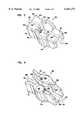
- FIG. 3is an enlarged, top perspective view of the slider device of FIG. 1;
- FIG. 4is an enlarged, bottom perspective view of the slider device of FIGS. 1 and 3;
- FIG. 5is a bottom plan view of the slider device depicted in FIGS. 3 and 4;
- FIG. 6is a cross-sectional view of the slider device depicted in FIG. 5 taken along the line 6--6 of FIG. 5;
- FIG. 7is a schematic view of the profiled elements of FIG. 2 having the slider device of FIGS. 1 and 3 through 6 attached thereto;
- FIG. 8is a schematic illustration of a first method of applying a slider device to a recloseable package, according to an example embodiment of the present invention.
- FIG. 9is a schematic illustration of a further step in the first method of applying a slider device to a recloseable package, according to an example embodiment of the present invention.
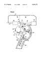
- FIG. 10is a cross-sectional schematic illustration of a second method of applying a slider device to a recloseable package, according to an example embodiment of the present invention.
- FIG. 11is a cross-sectional schematic illustration of a further step in the second method of FIG. 10 of applying a slider device to a recloseable package, according to an example embodiment of the present invention
- FIG. 12is a cross-sectional schematic illustration of yet a further step in the second method of FIG. 10 of applying a slider device to a recloseable package, according to an example embodiment of the present invention
- FIG. 13is a cross-sectional schematic illustration of a third method of applying a slider device to a recloseable package, according to an example embodiment of the present invention.
- FIG. 14is a cross-sectional schematic illustration of a further step in the third method of FIG. 13 of applying a slider device to a recloseable package, according to an example embodiment of the present invention.
- FIG. 15is a cross-sectional schematic illustration of yet a further step in the third method of FIG. 13 of applying a slider device to a recloseable package, according to an example embodiment of the present invention.
- the present inventionis applicable to applying a slider device to a variety of packaging arrangements. An appreciation of various aspects of the invention is best gained through a discussion of a preferred example of such a packaging arrangement and the slider device.
- FIG. 1illustrates an example packaging arrangement in the form of a recloseable, flexible package 10, for example, a polymeric package such as a plastic bag, having a recloseable closure mechanism 12, for example, interlocking profiled elements, and a slider device for opening and closing the closure mechanism 12.
- package 10may be resealable; that is, closure mechanism 12 not only closes package 10 but also seals package 10.
- the flexible package 10includes first and second opposed panel sections 13, 14, typically made from a flexible, polymeric, plastic film. With some manufacturing applications, the first and second panel sections 13, 14 are heat-sealed together along two side edges 20, 22 and meet at a fold line 23 in order to form a three-edged containment section for a product within an interior 24 of the package 10. In the embodiment shown, the fold line 23 comprises the bottom edge 25 of the package 10. Alternatively, two separate panel sections 13, 14 of plastic film may be used and heat-sealed together along the two side edges 20, 22 and at the bottom edge 25. Access is provided to the interior 24 of the package 10 through a mouth 26 at a top edge 27 of the package. In the particular embodiment shown, the mouth 26 extends the width of the package 10.
- the closure mechanism 12is illustrated in FIG. 1 at the mouth 26 of the flexible package 10. Alternatively, the closure mechanism 12 could be positioned on the package 10 at a location different from the mouth 26 of the package 10, depending on the application needs for the package 10.
- the closure mechanism 12can be one of a variety of closure mechanisms. In the particular embodiment illustrated in FIG. 2, the recloseable closure mechanism 12 is shown in the specific form of a zipper-type closure mechanism.
- zipper-type closure mechanismit is meant a structure having opposite interlocking or mating profiled elements that under the application of pressure will interlock and close the region between the profiles.
- the zipper-type closure mechanism in FIG. 2is an illustration of one example of a closure mechanism 12.
- the closure mechanism 12includes an elongated first closure profile 30 and an elongated second closure profile 40.
- the closure profiles 30, 40are manufactured separately from each other.
- the preferred first closure profile 30 depictedincludes a sealing flange or bonding strip 32, a base strip 33, a first closure member 34, first and second guide posts 36, 37, and an upper flange 39.
- the closure member 34extends from the base strip 33 and is generally projecting from the base strip 33.
- At a free end or tip of the closure member 34is a hook or catch 35.
- the guide posts 36, 37also extend from the base strip 33 and are generally projecting from the base strip 33. The guide posts 36, 37 aid in holding the closure mechanism 12 closed and in aligning the first closure profile 30 with the second closure profile 40 for interlocking.
- the bonding strip 32depends or extends downward from the second guide post 37 and can be attached to a first panel section, such as the first panel section 13 of the package 10 of FIG. 1.
- a first shoulder 38is defined by the intersection of the base strip 33 and bonding strip 32.
- the bonding strip 32is spaced a distance laterally from the base strip 33 to define a comer forming the shoulder 38.
- the upper flange 39extends upwardly from the base strip 33 and first guide post 36.
- the preferred second closure profile 40 depictedincludes a bonding strip 42, a base strip 43, a closure member 44, a guide post 46, and an upper flange 49.
- the closure member 44extends from the base strip 43 and is generally projecting from the base strip 43.
- At a free end or tip of the closure member 44is a hook or catch 45.
- the guide post 46also extends from the base strip 43 and is generally projecting from the base strip 43.
- the guide post 46aids in holding the closure mechanism 12 closed and aids in aligning the second closure profile 40 with the first closure profile 30 for interlocking.
- the bonding strip 42depends or extends downward from the guide post 46 and can be attached to a second panel section, such as the second panel section 14 of the package 10 of FIG. 1.
- a shoulder 48analogous to the shoulder 38, is formed at the comer of the bonding strip 42 and guide post 46.
- the first and second closure profiles 30, 40are designed to engage with one another to form the recloseable closure mechanism 12.
- the closure member 34 of the first closure profile 30extends from the base strip 33 an engagement distance.
- the closure member 44 of the second closure profile 40also extends from the base strip 43 an engagement distance. These engagement distances that the closure members 34, 44 extend are sufficient to allow mechanical engagement, or interlocking, between the first closure member 34 of the first closure profile 30 and the closure member 44 of the second closure profile 40.
- the catches 35, 45hook or engage each other.
- the closure profiles 30, 40are sealed together at their ends, such as at side edges 20, 22 in FIG. 1, to further aid in aligning the closure profiles 30, 40 for interlocking through processes such as ultrasonic crushing or welding.
- Pressureis applied to the closure profiles 30, 40 as they engage to form the openable sealed closure mechanism 12. Pulling the first closure profile 30 and the second closure profile 40 away from each other causes the two closure profiles 30, 40 to disengage, opening the package 10 of FIG. 1. This provides access to the interior 24 of the package 10 through the mouth 26.
- the closure profiles 30, 40are formed by two separate extrusions or through two separate openings of a common extrusion.
- the closure mechanism 12is made of a polymer, plastic material, such as polyethylene or polypropylene.
- the closure arrangement illustrated in FIG. 2is manufactured using conventional extrusion and heat sealing techniques.
- FIG. 1note that there is a cutout or notch 28 formed in the upper flanges 39, 49 (FIG. 2) of the closure mechanism 12.
- the preferred notch 28 shownincludes three straight edges or sides and is formed twice as long as the length of the spreader 66 of slider 50 (FIG. 5).
- the notch 28serves as a "parking place” for a slider device 50 and may also facilitate mounting the slider device 50 onto the recloseable package 10 during initial assembly.
- the edge closest to the side seal 20helps to create a stop member for the slider device 50.
- the slider device 50is provided to open and close the closure mechanism 12. Attention is now directed to FIGS. 3 and 4.
- One preferred slider device 50is illustrated in FIGS. 3 and 4 in perspective view and preferably comprises a one-piece unitary, molded plastic member with no moveable parts.
- the slider device 50includes a housing 52 for slidably engaging the closure mechanism 12.
- the housing 52is movable between a closed position of the package 10 when the housing 52 is adjacent the side edge 20 and an open position of the package 10 when the housing 52 is adjacent the side edge 22.
- FIG. 1illustrates the recloseable package 10 in an predominantly open position.
- the housing 52slides over the resealable closure mechanism 12 relative to the top edge 27 of the resealable package 10 to open and close mouth 26.
- the housing 52is preferably a multi-sided container configured for engaging or locking onto or over the closure mechanism 12.
- the housing 52includes a top wall 54.
- topit is meant that in the orientation of the slider device 50 shown in FIG. 3, the wall 54 is oriented above the remaining portions of the housing 52. It should be understood, of course, that if the housing 52 is moved from the orientation shown in FIG. 3, the top wall 54 will not be in a top orientation.
- the top wall 54defines a first end 55 and an opposite second end 56.
- the top wall 54also defines an open aperture 58. The open aperture 58 divides the top wall 54 between a first portion 60 and a second portion 61.
- the first portion 60generally comprises a flat, planar portion in extension from a periphery of the open aperture 58 to the edge defined by the first end 55.
- the second portion 61generally comprises a flat, planar portion in extension from a periphery of the open aperture 58 to the edge defined by the second end 56.
- Each of the first and second portions 60, 61defines a groove 63, 64 respectively.
- the aperture 58 and grooves 63, 64aid in providing a structure that may be more easily injection molded.
- the housing 52includes a separation structure for separating the first and second closure profiles 30, 40. That is, when the closure mechanism 12 is in a closed state such that the closure members 34, 44 are interlocked, the separation structure will apply a force to wedge open and pull the closure members 34, 44 apart from each other.
- the housing 52includes a plow or spreader 66 operating as a separation structure.
- the spreader 66in the preferred embodiment shown, extends or depends from the top wall 54.
- the spreader 66comprises first and second angled wedges 68, 69 separated by a gap 70 (FIG. 5) therebetween.
- first and second wedges 68, 69are angled toward each other, from the first end 55 of the slider device 50 to an opposite end of the wedges 68, 69, to form an overall triangular shaped spreader 66.
- the gap 70 between the first wedge 68 and second wedge 69helps to contribute to convenient manufacturing techniques for the housing 52, such as injection molding.
- the spreader 66only extends partially in the closure mechanism 12. More preferably, the spreader 66 only extends between the open flanges 39, 49 and does not penetrate the closure members 34, 44. This helps to ensure a leak-proof closure mechanism 12. In the preferred embodiment shown, the spreader 66 preferably extends about 0.125 inch from the first portion 60 of the top wall 54.
- the preferred housing 52 shownalso includes first and second side walls 72, 74.
- each of the first and second sidewalls 72, 74extends from and is cantilevered from the top wall 54 to form a slide channel 77 therebetween.
- the first and second sidewalls 72, 74are injection molded with the remaining parts of the housing 52.
- the housing 52comprises a single, unitary, integral piece of material with no additional materials welded, fastened, or bolted together.
- the sidewalls 72, 74can include texturization, such as ribs 75, to help improve gripping and handling by the user.
- FIG. 5note that the sidewalls 72, 74 diverge away from each other at the first end 55 in the first portion 60; form convex portions in a middle section; and are generally parallel in the second portion 61.
- the housing 52includes a system for permitting the housing 52 to slide along the closure mechanism 12 without becoming disengaged from the recloseable package 10.
- the system of the slider housing 52engages or interlocks with certain structure of the closure mechanism 12.
- the housing 52has a first and a second engaging leg construction 76, 78.
- the first leg construction 76preferably extends from the first sidewall 72 in a portion of the housing 52 that is under the open aperture 58. As illustrated in FIGS. 3 through 7, the leg constructions are preferably hooking constructions 76, 78.
- first hooking construction 76preferably includes a flange 80 in lateral extension from the first sidewall 72. Extending or projecting from flange 80 is a tip 82 oriented toward the top wall 54. As such, the tip 82, in combination with the flange 80, forms a hook or catch for slidable engagement with the shoulder 48 of the second closure profile 40.
- second hooking construction 78preferably extends from the second sidewall 74 and includes a flange 84 in extension from the second sidewall 74 and in a region of the housing 52 below the open aperture 58.
- a tip 86projects or extends from flange 84 in a direction oriented toward the top wall 54.
- the flange 84 and tip 86cooperate to form a hook or catch for engaging in a slidable manner with the shoulder 38 of the first closure profile 30.
- the first hooking construction 76is located closer to the top wall 54 than the second hooking construction 78. This is generally because, in the embodiment shown, the second sidewall 74 is longer than the first sidewall 72.
- Each of the first and second hooking constructions 76, 78has circular, partial cavities 87, 88, respectively, formed therein. These cavities 87, 88 help facilitate convenient manufacturing techniques, such as injection molding.
- the slider device 50preferably includes a system for guiding the slider device 50 between the side edges 20, 22 (FIG. 1) and for preventing the slider device 50 from sliding off the edge of the package 10 (FIG. 1).
- the systemincludes a guide construction 90 (FIG. 4).
- the guide construction 90is designed to project beyond the first and second ends 55, 56 of the top wall 54. This ensures that the guide construction 90 detects the side edges 20, 22 before any other structure on the housing 52 engages the sides 20, 22 of the package 10.
- the guide construction 90depends from the top wall 54, but could depend from other portions of the housing 52 in other embodiments.
- the guide construction 90comprises first and second bumpers or elongate fingers 92, 94.
- the first bumper or finger 92preferably is molded as part of the housing 52 to extend a distance of at least about 0.06 inch (1.5 mm) beyond the first end 55 of the first portion 60.
- the second bumper or finger 94likewise is preferably molded as part of the housing 52 to extend a distance of at least 0.06 inch (1.5 mm) beyond the second end 56 of the second portion 61.
- the first finger 92will abut or engage the side edge 20 to help contribute to preventing the housing 52 from sliding off of the recloseable package 10.
- the second finger 94will abut or engage the side edge 22 to prevent the housing 52 from sliding off of the recloseable package 10.
- the guide construction 90keeps the housing 52 within the boundaries or periphery defined by the side edges 20 and 22.
- the housing 52includes a system for reducing drag. That is, the housing 52 is designed such that the surface area contact between the housing 52 and the closure mechanism 12 is minimal.
- the systemincludes first and second drag reducing standoffs 96, 97.
- the first standoff 96preferably projects or extends from the first sidewall 72 as a protrusion or pin or rod.
- the second standoff 97projects or extends from the second sidewall 74.
- the first and second standoffs 96, 97project at least about 0.0085 inch (0.22 mm) from their respective sidewalls 72, 74.
- the first standoff 96extends the entire length between the bottom of the first sidewall 72 and the top wall 54.
- the second standoff 97extends the entire length between the top wall 54 and the bottom edge of the second sidewall 74.
- the standoffs 96, 97slidably communicate with the first and second closure profiles 30, 40, respectively. Because of the projection and extension of the standoffs 96, 97 relative to the remaining portions of the housing 52, the amount of surface area contact or material inducing friction between the housing 52 and the recloseable closure mechanism 12 is minimized. This permits easier manipulation of the slider device 50 by the user.
- the slider device 50may be slid relative to the recloseable closure mechanism 12 in a first direction or an opposite second direction.
- the spreader 66forces the closure members 34, 44 apart from each other.
- the spreader 66is spaced between the upper flanges 39, 49 of the profile members 30, 40 and opens the mouth 26 of the package 10 as the slider housing 52 is moved along the recloseable package 10 in the direction toward where the triangle of spreader 66 "points.”
- the openinghappens because the triangular shape of the spreader 66 operates as a cam to force the profile members 30, 40 apart, and thus to disengage the interlocking members 34, 44.
- the slider housing 12is moved relative to the closure mechanism 12 in the opposite direction.
- the closinghappens because the slide channel 77 between the sidewalls 72, 74 is narrower at end 56 (the end away from the spreader 66) and is wider at the end 55 (the end near the spreader 66).
- the spreader 66does not depend very far downwardly into the closure mechanism 12, and it never actually passes between the interlocking members 34, 44. Thus, this helps to prevent leaks in the closure mechanism 12, when the slider device 50 is in the closed position.
- the slider device housing 52may be moved until the first finger 92 abuts edge of the notch 28. To open the package 10, the slider housing 52 is moved in the opposite direction to the open position. Note that no extra tools are needed for operation.
- the package 10may be formed by either a blown extrusion process or by using a pre-formed roll of film.
- the filmis folded in the form shown in FIG. 1.
- the closure mechanism 12may be applied to the film panel sections 13, 14 by heat sealing the bonding strips 32, 42 to the film sections.
- the notch 28may be cut into the upper flanges 39, 49.
- the side seals at edges 20, 22may be formed, for example by ultrasonic crushing.
- the slider 50, in particular housing 52is then mounted over the closure mechanism 12, for example, by sliding it onto the notch 28.
- the sequence of these stepsmay be rearranged as preferred, however it is preferred that the closure mechanism 12 with notch 28 is attached to panel sections 13, 14 prior to mounting slider 50.
- one preferred technique for manufacturing the slider housing 52is injection molding. While other methods are possible, injection molding is convenient and preferred. In addition, injection molding allows for ornamental features, such as ribs 75, to be molded as part of the housing 52.
- slider 50has been mounted onto the closure mechanism 12 so that the legs, e.g., first and second hooking constructions 76, 78, snap over and engage the shoulders 38, 48, of the closure profiles 30, 40, respectively. Processes for mounting the slider 50 onto closure mechanism 12 of package 10 are provided below.
- FIGS. 8 and 9A schematic top plan view of a first embodiment of a process for mounting the slider 50 on the closure mechanism 12 is shown in FIGS. 8 and 9.
- a rotating carousel 100is used for positioning and attachment of slider 50 to closure mechanism 12.
- Guide devices 102, 104are used to firmly hold packages 10' during the application process.
- Inchoate packages 10'which have not been formed as individual bags, are shown in FIGS. 8 and 9 with top edge 27 including mouth 26 (not shown in FIG. 8; see FIG. 1) as the lowest most point of package 10'; bottom edge 25 (not shown in FIG. 8; see FIG. 1) would be at the top of the figure.
- inchoate packages 10'comprise parallel panel sections 13, 14 (not shown in FIG. 8; see FIG. 1), typically polymeric film sheets, and closure mechanism 12 attached to panels 13, 14.
- Packages 10'are connected at side edges 20, 22; that is, the bags have an interior compartment formed by seams at points where the side edges 20, 22 would be, but bags have not been separated yet and remain as a continuous web.
- the polymeric websmay not yet have any welds or seams that correspond to edges 20, 22.
- the method and apparatus of the present inventioncan be used to mount slider 50 on a completed package 10.
- a plurality of sliders 50is retained in stacked configuration by a guide chute 150.
- Sliders 50should be stacked in such a manner that when slider 50 is deposited into carousel 100, top wall 54 contacts retention base 112 and second end 56 of slider housing 52 faces backwall 114, for reasons as will be described below.
- slider 50is deposited onto retention base 112 of retention area 110 of carousel 100.
- Carousel 100is shown as having four equally spaced retention areas 110; however, more or less areas 110 may be present depending on carousel diameter, carousel rotation speed, and overall process speed.
- Retention area 110is sized to retain slider 50 securely therein during rotation of carousel 100.
- a retaining pin 125can be used to help retain slider 50 within retention area 110. Retaining pin 125 extends from, and is retractable into, backwall 114 of retaining area 110. Pin 125 may be perpendicular to backwall 114, may be parallel to retention base 112, or both.
- the apparatus of the present inventionpreferably includes an ejection system for facilitating mounting slider 50 onto package 10'.
- the ejection systemhelps remove slider 50 from its position in retention area 110 and mount it onto closure mechanism 12.
- the ejection systemcomprises a extendible/retractable pin 120 in relation with retention base 112 of retention area 110.
- Retention area 110 and retention base 112are configured so that the contact end 124 of pin 120 can extend through retention base 112 into retention area 110 to contact top wall 54 of slider 50.
- Pin 120may include a spring 122 to facilitate the pin's retraction out from retention area 110.
- spring 122is at least partially compressed, thereby allowing pin 120 to extend out into retention area 110.
- spring 122is allowed to expand.
- Pin 120 and spring 122 extension and retractioncan be controlled by cam 130, which is positioned at the center of carousel 100.
- cam 130is a non-circular shaped piece used to impart motion to pin 120 as pin base 123 contacts cam 130.
- Cam 130is stationary in respect to carousel 100.
- the extended end 132 of cam 130contacts pin base 123 and pushes pin 120 radially away from the center 100C of carousel 100 to its periphery 100P.
- the radial force on pin base 123pushes pin 120, and contact end 124, outward to periphery 100P, thereby compressing spring 122 and allowing contact end 124 of pin 120 to extend into retention area 110.
- the extended end 132 of cam 130no longer contacts pin base 123, thereby removing the radial force on pin base 123 and allowing spring 122 to expand to its original length and pin 120 to retract.
- pin 120When retention area 110 is empty, that is, without a slider 50 therein, pin 120 should be retracted into carousel 100, preferably below retention base 112, so that little or no portion of pin 120 extends into retention area 110.
- slider 50When deposited from chute 150, slider 50 sits level on retention base 112 in retention area 110 with top wall 54 of slider housing 52 in contact with retention base 112 and second end 56 of slider housing 52 in contact with retention area back wall 114. Retaining pin 125 extends to hold slider 50 in area 110.
- carousel 100 with slider 50 secured in retention area 110rotates in a counter-clockwise direction so that first end 55 of slider housing 52 is the leading edge of slider 50.
- Packages 10'move from the right side of the figures to the left at a speed proportional to the rotation of carousel 100 and the spacing of retention areas 110 with sliders 50 therein.
- the speed of inchoate packages 10', or packages 10should be set so that each slider 50 meets a notch 28 in a package 10'. Likewise, each notch 28 should meet with a slider 50. This is explained further below.
- FIGS. 8 and 9show The method for mounting slider 50 onto closure mechanism 12 in reference to FIGS. 8 and 9.
- Slider 50positioned in retention area 110, is brought into contact with package 10' so that first end 55 of housing 52 intersects package 10' at notch 28 at an angle, for example, 20-60°, preferably at about 45°.
- FIG. 8shows first end 55 of slider 50 partially mounted on closure mechanism 12 at notch 28.
- Pin 120is partially extended.
- First end 55, in particular wedges 68, 69 (FIGS. 3 and 5) of housing 52is forced onto closure profiles 30, 40 (FIGS. 2 and 7) of closure mechanism 12 by fully extended pin 120 in FIG. 9 so that flanges 39, 49 (FIG. 2) and first and second closure profiles 30, 40 distort from their original position (shown in FIGS.
- first and second hooking constructions 76, 78(FIGS. 4, 6 and 7) pass over closure profiles 30, 40.
- the enlarged end 132 of cam 130contacts pin base 123 simultaneously or soon after first end 55 intersects notch 28.
- Pin 120is pushed radially outward by cam 130 so that contact end 124 extends into retaining area 110 and ejects slider 50 from retaining area 110.
- retaining pin 125should be retracted to allow slider 50 to be removed from retaining area 110. Pin 125 may retract immediately before, or during the mounting process.
- package 10'should be securely held during the mounting process to minimize any displacement of package 10' in respect to carousel 100.
- Guides 102, 104 or other clamping devicecan be used to stabilize the web of packages 10' during the mounting of slider 50.
- Package 10 with slider 50 mounted thereonis moved away from carousel 100 and another package 10 is positioned for mounting of a slider 50 thereon.
- Slider guide chute 150deposits another slider 50 into an aligned retaining area 110.
- movement of the package webmay be continuous or may be indexed. That is, package 10 may be stationary during the mounting of slider 50 and is moved so that a next package 10 can be positioned for mounting of a slider 50.
- carousel 100may be stationary during the mounting process and indexed to the next retention area 110 with slider 50 when the next slider 50 is to be mounted, or carousel 100 may continuously rotate. Preferably, both the package web and carousel 100 move continuously during the mounting process.
- FIGS. 10 through 12show slider 50 being mounted onto closure mechanism 12 having first and second closure profiles 30, 40.
- first and second upper flanges 39, 40 of first and second closure profiles 30, 40, respectivelyare distorted from their original position (shown in FIGS. 2 and 7) to facilitate the mounting of slider 50 onto closure mechanism 12.
- distortedit is meant that the flanges experience elastic deformation; that is, the shape of each of at least one of the flanges is deformed by some force, and when the force is removed, the flange returns to its original shape before being deformed.
- First and second hooking constructions 76, 78 of slider 50may also be distorted during the process of mounting slider 50 onto closure mechanism 12.
- slider 50Before mounting slider 50 onto the closure mechanism 12, slider 50 is positioned within a support 205 that aligns slider 50 with the closure mechanism 12 on which slider 50 will be mounted.
- the support 205can be configured for manual placement of slider 50 therein, or slider 50 may be deposited into the support 205 by any automated mechanism. Preferably, a continuous supply of sliders 50 is fed to the support 205.
- support 205includes a slider retainer 210.
- FIG. 10shows slider 50 held in the slider retainer 210 in a manner so that top wall 54 of slider housing 52, and preferably all of housing 52, is positioned within retainer 210.
- Retainer 210includes an ejection system 202 for urging slider 50 out from retainer 210 and onto closure mechanism 12.
- a pin 220which extends into the area occupied by slider 50, can be used as an ejection system 202 to push slider 50 from retainer 210.
- pin 220is extendible from, and retractable to, backwall 212 of retainer 210.
- Pin 220may be configured to seat within open aperture 58 (FIG. 3) of housing 52 to increase stabilization of slider 50 on pin 220.
- Slider 50is positioned so that first and second hooking constructions 76, 78 extend outward from retainer 210 and pin 220 toward closure mechanism 12.
- Recloseable closure mechanism 12comprising first and second closure profiles 30, 40, is positioned so that first and second upper flanges 39, 49 extend toward slider 50 in retainer 210.
- package 10may exist as an individual package 10 or as inchoate package 10' during the process of attaching slider 50. Additionally, slider 50 can be mounted onto closure mechanism 12 without closure mechanism 12 being attached to first and second panel sections 13, 14.
- closure mechanism 12is preferably securely held in some manner during the mounting process so that any displacement of closure mechanism 12 in respect to retainer 210 is minimized.
- Adjacent to first and second closure profiles 30, 40are closure guide walls 213, 214, respectively, which provide proper placement for closure profiles 30, 40.
- Guide walls 213, 214also provide a support surface for the mounting of a flange distorting system 200 used for the process of mounting slider 50 onto closure mechanism 12.
- a flange distorting system 200used for the process of mounting slider 50 onto closure mechanism 12.
- the flange distorting systempreferably includes a mechanism that allows the flange distorting system to be used repeatedly, rather than a single use.
- first and second guides 230, 240are triangular first and second guides 230, 240 with their sloped surfaces directly adjacent upper flanges 39, 49, respectively, that are used to distort flanges 39, 49.
- Each of first and second guides 230, 240, respectively,is communicably attached to first and second guide levers 231, 241 and first and second springs 232, 242, respectively, which allow first and second guides to be used repeatedly.
- First and second guides 230, 240 and first and second guide levers 231, 241are moveable along the length of closure guide walls 213, 214, for example through a slot extending through guide walls 213, 214.
- first and second guides 230, 240are positioned between closure profiles 30, 40 and first and second hooking constructions 76, 78, as shown in FIG. 10.
- first guide 230is between first closure profile 30 and hooking construction 78
- second guide 240is between second closure profile 40 and hooking construction 76.
- slider 50is positioned in slider retainer 210, and closure mechanism 12 is aligned between closure guide walls 213, 214 with first and second guides 230, 240 in an original position with springs 232, 242 extended.
- Pin 220extends from retainer backwall 212, contacting top wall 54 of slider housing 52 and pushing slider 50 out of retainer 210 until first and second hooking constructions 76, 78 contact and abut first and second guides 230, 240, respectively.
- guides 230, 240are pushed by hooking constructions 76, 78 so that the sidewalls of guides 230, 240, make contact with upper flanges 39, 49.
- FIG. 11illustrates how upper flanges 39, 49 are distorted by guides 230, 240 as guides 230, 240 are pushed by slider 50.
- Flanges 39, 40are distorted or bent inward toward each other by the sloped inner walls of guides 230, 240, thereby decreasing the overall width of closure mechanism 12 at that distal end.
- first and second hooking constructions 76, 78 of slider 50can be pushed over flanges 39, 49 and closure mechanism 12 until slider 50 is snapped over shoulders 38, 48, as is finally shown in FIG. 12.
- Hooking constructions 76, 78 and other portions of slider housing 52may be slightly distorted outward during the mounting process by the force of pushing slider 50 over closure mechanism 12.
- Closure guide walls 213, 214can be sloped to allow room for expansion of slider housing 52 as it is pushed onto closure mechanism 12.
- Closure mechanism 12as attached to package 10, inchoate package 10', or individually, can be manually placed within closure guide walls 213, 214 or may be automatically placed and removed.
- Package 10 and closure mechanism 12may be limited to individual bags placed within closure guide walls 213, 214 or may be an extended web of inchoate packages 10', such as described in the first process embodiment, above.
- FIGS. 13 through 15show slider 50 being mounted on a closure mechanism 12 having first and second closure profiles 30, 40.
- first and second hooking constructions 76, 78 of slider 50are distorted from their original position to facilitate the mounting of slider 50 onto closure mechanism 12.
- the hooking construction 76, 78are elastically deformed.
- First and second upper flanges 39, 49 of first and second closure profiles 30, 40, respectively,may also be distorted during the process of mounting slider 50 onto closure mechanism 12.
- slider 50Before mounting slider 50 onto closure mechanism 12, slider 50 is positioned within a support 305 that aligns slider 50 with the closure mechanism 12 on which slider 50 will be mounted.
- the support 305can be configured for manual placement of slider 50 therein, or slider 50 may be deposited onto support 305 by any automated mechanism.
- a continuous supply of sliders 50is fed to the support 305.
- support 305includes a slider retainer 310.
- FIG. 13shows a slider 50 held in slider retainer 310 in a manner so that top wall 54 of slider housing 52, and preferably all of housing 52, is positioned within retainer 310.
- Retainer 310includes an ejection system 302 for urging slider 50 out from retainer 310 onto closure mechanism 12.
- a pin 320which extends into the area occupied by slider 50, can be used as ejection system 302 to push slider 50 from retainer 310.
- pin 320is extendible from, and retractable to, backwall 312 of retainer 310.
- Pin 320may be configured to seat within or engage with open aperture 58 (FIG. 3) of housing 52 to increase stabilization of slider 50 on pin 320.
- Slider 50is positioned so that first and second hooking constructions 76, 78 extend outward from retainer 310 and pin 320 toward closure mechanism 12.
- Recloseable closure mechanism 12comprising first and second closure profiles 30, 40, is positioned so that first and second upper flanges 39, 49 extend toward slider 50 in retainer 310.
- package 10may exist as an individual package 10 or as an inchoate package 10' during the process of mounting slider 50. Additionally, slider 50 can be mounted onto closure mechanism 12 without closure mechanism being attached to first and second panel sections 13, 14.
- closure mechanism 12is preferably securely held in some manner during the mounting process so that any displacement of closure mechanism 12 in respect to retainer 310 is minimized.
- Adjacent first and second closure profiles 30, 40are closure guide walls 313, 314, respectively, which provide for proper placement for closure profiles 30, 40.
- Closure guide walls 313, 314also provide a support surface for the mounting of a hook distorting system 300 used for the process of mounting slider 50 onto closure mechanism 12.
- a hook distorting system 300used for the process of mounting slider 50 onto closure mechanism 12.
- the hook distorting system 300preferably includes a mechanism that allows the hook distorting system to be used repeatedly, rather than a single use.
- first and second lifts 330, 340which have sloped surfaces and a hooked end, used for distorting first and second hooking constructions 76, 78.
- Each of first and second lifts 330, 340, respectively,is communicably attached to first and second guide levers 331, 341 and first and second springs 332, 342, respectively, which allow first and second lifts to be used repeatedly.
- communicably attachedit is meant that lift 330, 340 and levers 331, 332 are physically connected and that movement of lifts 330, 340 produces likewise movement of levers 331, 341.
- First and second lifts 330, 340 and first and second guide levers 331, 341are moveable along the length of closure guide walls 313, 314, for example through a slot extending through guide walls 313, 314. With springs 332, 342 in their fully extended position, first and second lifts 330, 340 are positioned between closure profiles 30, 40, and first and second hooking constructions 76, 78 as shown in FIG. 13.
- closure mechanism 12is aligned between closure guide walls 313, 314 with first and second lifts 330, 340 in an original position with springs 332, 342 extended.
- Pin 320extends retainer backwall 312, contacting top wall 54 of slider housing 52 and pushing slider 50 out of retainer 310 until first and second hooking constructions 76, 78 contact and abut first and second lifts 330, 340, respectively.
- Each lift 330, 340is shown having a hooked end 335, 345 that is insertable between hooking constructions 76, 78, respectively, and preferably catches hooking constructions 76, 78.
- lifts 330, 340are pushed back along walls 313, 314 so that hooking constructions 76,78 are spread and optionally, lifts 330, 340 make contact with upper flanges 39, 49.
- FIG. 14shows how first and second hooking constructions 76, 78 are distorted by lifts 330, 340 as lifts 330, 340 are pushed along closure guide walls 313, 314 by slider 50.
- First and second hooking constructions 76, 78are distorted or bent outward away from each other, thereby increasing the overall width of slider housing 52 at that point. With the width of housing 52 increased, slider 50 can be pushed over closure mechanism 12 until the slider 50 is snapped over shoulders 38, 48, as shown in FIG. 15.
- First and second closure profiles, in particular upper flanges 39, 49, and other portions of closure mechanism 12may be slightly distorted inward by the force of pushing slider 50 over closure mechanism 12.
- closure mechanism 12 with the slider 50 mounted thereonis removed from between closure guide walls 313, 314, lifts 330, 340 are returned to their original position by the return of springs 332, 342 to their extended position.
- pin 320is retracted toward backwall 312 so that slider retainer 310 is ready to accept another slider 50 for mounting onto another closure mechanism 12.
- Closure mechanism 12as attached to package 10, inchoate package 10'. Or individually, can be manually placed within closure guide lifts 330, 340 or may be automatically placed and removed. Package 10 and closure mechanism 12 may be limited to individual bags placed within closure guide lifts 313, 314 or may be an extended web or inchoate package 10" such as described in the first and second process embodiments, above.
Landscapes
- Engineering & Computer Science (AREA)
- Mechanical Engineering (AREA)
- Bag Frames (AREA)
- Slide Fasteners (AREA)
Abstract
Description
Claims (10)
Priority Applications (3)
| Application Number | Priority Date | Filing Date | Title |
|---|---|---|---|
| US09/363,626US6161271A (en) | 1999-07-29 | 1999-07-29 | Method for mounting a slider mechanism to recloseable flexible packaging |
| EP00114981AEP1072525B1 (en) | 1999-07-29 | 2000-07-20 | Method for mounting a slider mechanism to a recloseable flexible packaging |
| DE60005611TDE60005611T2 (en) | 1999-07-29 | 2000-07-20 | Process for attaching a slide to a resealable packaging made of flexible material |
Applications Claiming Priority (1)
| Application Number | Priority Date | Filing Date | Title |
|---|---|---|---|
| US09/363,626US6161271A (en) | 1999-07-29 | 1999-07-29 | Method for mounting a slider mechanism to recloseable flexible packaging |
Publications (1)
| Publication Number | Publication Date |
|---|---|
| US6161271Atrue US6161271A (en) | 2000-12-19 |
Family
ID=23430995
Family Applications (1)
| Application Number | Title | Priority Date | Filing Date |
|---|---|---|---|
| US09/363,626Expired - Fee RelatedUS6161271A (en) | 1999-07-29 | 1999-07-29 | Method for mounting a slider mechanism to recloseable flexible packaging |
Country Status (3)
| Country | Link |
|---|---|
| US (1) | US6161271A (en) |
| EP (1) | EP1072525B1 (en) |
| DE (1) | DE60005611T2 (en) |
Cited By (51)
| Publication number | Priority date | Publication date | Assignee | Title |
|---|---|---|---|---|
| USD451378S1 (en) | 2000-10-20 | 2001-12-04 | Kraft Foods Holdings, Inc. | Reclosable bag having slider closure |
| US6418605B1 (en)* | 2000-07-06 | 2002-07-16 | Reynolds Consumer Products, Inc. | Method and apparatus of applying slider device to a recloseable zipper arrangement |
| US6439771B1 (en) | 2000-03-15 | 2002-08-27 | Webster Industries Division Chelsea Industries, Inc. | Zippered resealable closure |
| US6442819B1 (en)* | 2000-07-06 | 2002-09-03 | Reynolds Consumer Products, Inc. | Method and apparatus of applying slider device to a recloseable zipper arrangement |
| US6450686B1 (en)* | 2000-11-29 | 2002-09-17 | Reynolds Consumer Products, Inc. | Resealable package having a reinforced slider device |
| US6460238B1 (en) | 2001-07-24 | 2002-10-08 | Pactiv Corporation | Plastic bag slider and end termination installation assembly and method |
| US6499272B2 (en) | 1997-11-07 | 2002-12-31 | Huntsman Kcl Corporation | Method for placing a product in a flexible recloseable container |
| US6517473B1 (en) | 2001-09-13 | 2003-02-11 | Pactiv Corporation | Device and method for installing sliders on reclosable fasteners for plastic bags |
| US6609353B1 (en)* | 1998-06-08 | 2003-08-26 | Illinois Tool Works Inc. | Application system for sliders at form-fill-seal machine |
| US6616333B2 (en) | 2000-09-22 | 2003-09-09 | Kraft Foods Holdings, Inc. | Fastener closure arrangement for flexible packages |
| US20030182784A1 (en)* | 2001-11-19 | 2003-10-02 | The Glad Products Company | Method and apparatus for assembling slider members onto interlocking fastening strips |
| US20030183314A1 (en)* | 2002-03-11 | 2003-10-02 | Lawrence Share | Apparatus for attaching sliders onto zipper bags and film |
| US20030236160A1 (en)* | 2000-07-06 | 2003-12-25 | Kettner Catherine E. | Method and apparatus for positioning applied slider |
| US6675558B2 (en) | 2001-04-18 | 2004-01-13 | Kraft Foods Holdings, Inc. | Method for manufacturing flexible packages having slide closures |
| US20040020025A1 (en)* | 2002-07-31 | 2004-02-05 | Ronald Cortigiano | Retractable zipper guide for slider insertion apparatus |
| US20040020035A1 (en)* | 2002-07-30 | 2004-02-05 | Ronald Cortigiano | Method and apparatus for positioning sliders for automated slider insertion |
| US20040020034A1 (en)* | 2002-07-31 | 2004-02-05 | Ronald Cortigiano | Method and apparatus for gripping zipper tape during slider insertion |
| US6688079B2 (en) | 2001-04-18 | 2004-02-10 | Kraft Foods Holdings, Inc. | Method for manufacturing flexible packages having slide closures |
| US6688080B2 (en) | 2001-04-18 | 2004-02-10 | Kraft Foods Holdings, Inc. | Method for manufacturing flexible packages having slide closures |
| US20040082456A1 (en)* | 2002-10-25 | 2004-04-29 | Tom East | Slider applicator |
| US6769229B2 (en) | 2001-08-30 | 2004-08-03 | Kraft Foods Holdings, Inc. | Method for manufacturing flexible packages having slide closures |
| US20040161169A1 (en)* | 2003-02-14 | 2004-08-19 | Fenzl Eric J. | Molded sliders for actuating zippers in reclosable packages |
| US6780146B2 (en) | 2002-09-17 | 2004-08-24 | Pactiv Corporation | Methods for applying sliders to reclosable plastic bags |
| US20040229740A1 (en)* | 2003-05-12 | 2004-11-18 | Crunkleton Gregory H. | Method and apparatus for inserting sliders during automated manufacture of reclosable bags |
| US6820393B2 (en) | 2001-04-18 | 2004-11-23 | Kraft Foods Holdings, Inc. | Apparatus for manufacturing flexible packages having slide closures |
| US6834474B2 (en) | 1999-07-29 | 2004-12-28 | Kraft Foods Holdings, Inc. | Package with zipper closure |
| US20050015957A1 (en)* | 1999-06-10 | 2005-01-27 | The Glad Products Company | Method and apparatus for assembling slider members onto interlocking fastening strips |
| US6863646B2 (en) | 2002-06-19 | 2005-03-08 | Kraft Foods Holdings, Inc. | Reclosable system for flexible packages having interlocking fasteners |
| US6871473B1 (en)* | 2000-08-10 | 2005-03-29 | Pactiv Corporation | Method and apparatus for making reclosable plastic bags using a pre-applied slider-operated fastener |
| US6884207B2 (en) | 2002-10-25 | 2005-04-26 | Kraft Foods Holdings, Inc. | Fastener closure arrangement for flexible packages |
| US6907713B2 (en) | 1997-11-07 | 2005-06-21 | Pliant Corporation | Method and apparatus for placing a product in a flexible recloseable container |
| US6918234B2 (en) | 2002-02-21 | 2005-07-19 | Pactiv Corporation | Process for attaching slider-operated closure on form-fill-seal packaging machinery |
| US6939041B2 (en) | 2003-01-29 | 2005-09-06 | Kraft Foods Holdings, Inc. | Fastener closure arrangement for flexible packages |
| US20050194417A1 (en)* | 2004-03-05 | 2005-09-08 | Clark Woody | Apparatus for and method of moving a slider along mating zipper elements |
| US20050197240A1 (en)* | 2004-03-05 | 2005-09-08 | Clark Woody | Apparatus for and method of positioning a slider on mating zipper elements |
| US20050220372A1 (en)* | 2002-03-22 | 2005-10-06 | Withers Philip C | Bag with crimped portion to retain slider |
| US6983573B2 (en) | 2002-06-07 | 2006-01-10 | Reynolds Consumer Products, Inc. | Method of applying a slider device to an open closure mechanism on a resealable bag |
| US20060171610A1 (en)* | 2005-01-31 | 2006-08-03 | Buchman James E | Internal gripping slider and method |
| US20060185325A1 (en)* | 2005-02-22 | 2006-08-24 | Alcoa, Inc. | Method of applying sliders, duplex packaging machine and slider applicator therefor |
| US7254873B2 (en) | 1998-06-04 | 2007-08-14 | Illinois Tool Works, Inc. | Scored tamper evident fastener tape |
| US20070271874A1 (en)* | 2004-03-24 | 2007-11-29 | Illinois Tool Works Inc. | Application of Zipper Lengths to a Web |
| US7306370B2 (en) | 2003-07-31 | 2007-12-11 | Kraft Foods Holdings, Inc. | Shrouded flexible packages |
| US7341160B2 (en) | 2002-08-08 | 2008-03-11 | Pactiv Corporation | Reclosable package having an accessible zipper and a method for making the same |
| USRE40284E1 (en) | 1999-08-12 | 2008-05-06 | Pactiv Corporation | Methods of making and filling a fill-through-the-top package |
| US7398953B2 (en) | 2004-12-22 | 2008-07-15 | Cti Industries, Inc. | One way valve for fluid evacuation from a container |
| US20100105535A1 (en)* | 2007-01-10 | 2010-04-29 | Isabelle Moulin | Device for applying runners on closure profiles |
| FR2941136A1 (en)* | 2009-01-21 | 2010-07-23 | S2F Flexico | DEVICE AND METHOD FOR PLACING A CURSOR ON A BAG WITH CLOSURE PROFILES. |
| US7972064B2 (en) | 2004-12-22 | 2011-07-05 | Cti Industries Corporation | One way valve and container |
| US8122687B2 (en) | 2003-07-31 | 2012-02-28 | Kraft Foods Global Brands Llc | Method of making flexible packages having slide closures |
| CN101786517B (en)* | 2009-12-31 | 2012-06-06 | 温州新大自封袋设备有限公司 | Automatic locking head device |
| US20190223562A1 (en)* | 2017-08-28 | 2019-07-25 | Reynolds Presto Products Inc. | Slider insertion apparatus and methods |
Citations (26)
| Publication number | Priority date | Publication date | Assignee | Title |
|---|---|---|---|---|
| US2879588A (en)* | 1952-06-24 | 1959-03-31 | Louis H Morin | Method of and apparatus for assembling sliders with separable fastener stringers |
| US3115689A (en)* | 1961-01-19 | 1963-12-31 | Flexigrip Inc | Slider for fastener strips |
| US3122807A (en)* | 1960-07-22 | 1964-03-03 | Edgar M Ausnit | Slider for a pouch and the like |
| US3230593A (en)* | 1962-07-26 | 1966-01-25 | Flexigrip Inc | Slide fastener for profiled strips |
| US3324520A (en)* | 1965-06-10 | 1967-06-13 | Ausnit Steven | Slider for fastener strips |
| US3426396A (en)* | 1967-03-07 | 1969-02-11 | Leon Ker Laguerre | Profiled strip slide fastener |
| US3629926A (en)* | 1966-06-27 | 1971-12-28 | Masayuki Maeda | Apparatus for automatically assembling slide fasteners |
| US3660875A (en)* | 1968-04-29 | 1972-05-09 | Minigrip Inc | Slider for sliding clasp fastener |
| US3701192A (en)* | 1970-01-26 | 1972-10-31 | Minigrip Inc | Mechanism for assembling sliders for interlocking fastener strips |
| US3701191A (en)* | 1970-01-12 | 1972-10-31 | Minigrip Inc | Apparatus for assembling a slider on a fastener strip |
| US3713923A (en)* | 1968-02-26 | 1973-01-30 | Minigrip Inc | Method of assembling slider with a profiled strip separable fastener |
| US3790992A (en)* | 1971-06-30 | 1974-02-12 | Minigrip Inc | Profiled closing members with slide |
| US3806998A (en)* | 1971-02-22 | 1974-04-30 | Minigrip Inc | Elastically flexible fastener |
| US3889341A (en)* | 1972-12-27 | 1975-06-17 | Yoshida Kogyo Kk | Apparatus for applying sliders to a slide fastener chain |
| US4262395A (en)* | 1978-03-09 | 1981-04-21 | Hans Bud | Sliding clasp fastening means |
| US4581006A (en)* | 1982-08-31 | 1986-04-08 | Minigrip, Incorporated | Method of and means for positioning sliders on zippers for reclosable bags |
| US5067208A (en)* | 1991-03-22 | 1991-11-26 | Mobil Oil Corporation | Plastic reclosable fastener with self-locking slider |
| US5088971A (en)* | 1991-03-22 | 1992-02-18 | Mobil Oil Corporation | Method of making protruding end stops for plastic reclosable fastener |
| US5113567A (en)* | 1990-08-08 | 1992-05-19 | Yoshida Kogyo K. K. | Method of and apparatus for feeding an array of sliders |
| US5131121A (en)* | 1991-03-22 | 1992-07-21 | Mobil Oil Corporation | Protruding end stops for plastic reclosable fastener |
| US5211482A (en)* | 1991-08-19 | 1993-05-18 | Minigrip, Inc. | Closure for post filling application to packaging |
| US5283932A (en)* | 1993-06-10 | 1994-02-08 | Mobil Oil Corporation | Flexible plastic zipper slider with rigidizing structure for assembly with profiled plastic zipper |
| US5431760A (en)* | 1994-05-02 | 1995-07-11 | Mobil Oil Corporation | Zipper slider insertion through split track |
| US5769772A (en)* | 1996-08-13 | 1998-06-23 | Tenneco Packaging Inc. | Packages made with both high-frequency/radio-frequency seals and conventional heat/pressure seals using combinations of polar and non-polar polymers |
| US5788378A (en)* | 1996-09-27 | 1998-08-04 | Tenneco Packaging Specialty And Consumer Products Inc. | Reclosable stand-up bag |
| US5833791A (en)* | 1996-08-16 | 1998-11-10 | Tenneco Packaging | Conforming end stops for a plastic zipper |
Family Cites Families (4)
| Publication number | Priority date | Publication date | Assignee | Title |
|---|---|---|---|---|
| GB1012988A (en)* | 1963-06-10 | 1965-12-15 | E P S Res & Dev Ltd | Sliding clasp fasteners |
| DE3208245A1 (en)* | 1982-03-08 | 1983-09-15 | ASF Gleitverschluß GmbH, 8500 Nürnberg | Method of mounting a slider on fastener strips of a profiled strip fastener, and slider, and device for carrying out the method |
| US5070583A (en)* | 1990-03-07 | 1991-12-10 | Mobil Oil Corporation | Gull wing zipper slider |
| EP1139810B1 (en)* | 1998-11-18 | 2004-03-03 | Reynolds Consumer Products, Inc. | Resealable closure mechanism having a slider device and methods |
- 1999
- 1999-07-29USUS09/363,626patent/US6161271A/ennot_activeExpired - Fee Related
- 2000
- 2000-07-20DEDE60005611Tpatent/DE60005611T2/ennot_activeExpired - Fee Related
- 2000-07-20EPEP00114981Apatent/EP1072525B1/ennot_activeExpired - Lifetime
Patent Citations (26)
| Publication number | Priority date | Publication date | Assignee | Title |
|---|---|---|---|---|
| US2879588A (en)* | 1952-06-24 | 1959-03-31 | Louis H Morin | Method of and apparatus for assembling sliders with separable fastener stringers |
| US3122807A (en)* | 1960-07-22 | 1964-03-03 | Edgar M Ausnit | Slider for a pouch and the like |
| US3115689A (en)* | 1961-01-19 | 1963-12-31 | Flexigrip Inc | Slider for fastener strips |
| US3230593A (en)* | 1962-07-26 | 1966-01-25 | Flexigrip Inc | Slide fastener for profiled strips |
| US3324520A (en)* | 1965-06-10 | 1967-06-13 | Ausnit Steven | Slider for fastener strips |
| US3629926A (en)* | 1966-06-27 | 1971-12-28 | Masayuki Maeda | Apparatus for automatically assembling slide fasteners |
| US3426396A (en)* | 1967-03-07 | 1969-02-11 | Leon Ker Laguerre | Profiled strip slide fastener |
| US3713923A (en)* | 1968-02-26 | 1973-01-30 | Minigrip Inc | Method of assembling slider with a profiled strip separable fastener |
| US3660875A (en)* | 1968-04-29 | 1972-05-09 | Minigrip Inc | Slider for sliding clasp fastener |
| US3701191A (en)* | 1970-01-12 | 1972-10-31 | Minigrip Inc | Apparatus for assembling a slider on a fastener strip |
| US3701192A (en)* | 1970-01-26 | 1972-10-31 | Minigrip Inc | Mechanism for assembling sliders for interlocking fastener strips |
| US3806998A (en)* | 1971-02-22 | 1974-04-30 | Minigrip Inc | Elastically flexible fastener |
| US3790992A (en)* | 1971-06-30 | 1974-02-12 | Minigrip Inc | Profiled closing members with slide |
| US3889341A (en)* | 1972-12-27 | 1975-06-17 | Yoshida Kogyo Kk | Apparatus for applying sliders to a slide fastener chain |
| US4262395A (en)* | 1978-03-09 | 1981-04-21 | Hans Bud | Sliding clasp fastening means |
| US4581006A (en)* | 1982-08-31 | 1986-04-08 | Minigrip, Incorporated | Method of and means for positioning sliders on zippers for reclosable bags |
| US5113567A (en)* | 1990-08-08 | 1992-05-19 | Yoshida Kogyo K. K. | Method of and apparatus for feeding an array of sliders |
| US5088971A (en)* | 1991-03-22 | 1992-02-18 | Mobil Oil Corporation | Method of making protruding end stops for plastic reclosable fastener |
| US5067208A (en)* | 1991-03-22 | 1991-11-26 | Mobil Oil Corporation | Plastic reclosable fastener with self-locking slider |
| US5131121A (en)* | 1991-03-22 | 1992-07-21 | Mobil Oil Corporation | Protruding end stops for plastic reclosable fastener |
| US5211482A (en)* | 1991-08-19 | 1993-05-18 | Minigrip, Inc. | Closure for post filling application to packaging |
| US5283932A (en)* | 1993-06-10 | 1994-02-08 | Mobil Oil Corporation | Flexible plastic zipper slider with rigidizing structure for assembly with profiled plastic zipper |
| US5431760A (en)* | 1994-05-02 | 1995-07-11 | Mobil Oil Corporation | Zipper slider insertion through split track |
| US5769772A (en)* | 1996-08-13 | 1998-06-23 | Tenneco Packaging Inc. | Packages made with both high-frequency/radio-frequency seals and conventional heat/pressure seals using combinations of polar and non-polar polymers |
| US5833791A (en)* | 1996-08-16 | 1998-11-10 | Tenneco Packaging | Conforming end stops for a plastic zipper |
| US5788378A (en)* | 1996-09-27 | 1998-08-04 | Tenneco Packaging Specialty And Consumer Products Inc. | Reclosable stand-up bag |
Cited By (94)
| Publication number | Priority date | Publication date | Assignee | Title |
|---|---|---|---|---|
| US6907713B2 (en) | 1997-11-07 | 2005-06-21 | Pliant Corporation | Method and apparatus for placing a product in a flexible recloseable container |
| US8127517B2 (en) | 1997-11-07 | 2012-03-06 | Illinois Tool Works Inc. | Method and apparatus for placing a product in a flexible recloseable container |
| US6962034B2 (en) | 1997-11-07 | 2005-11-08 | Illinois Tool Works Inc. | Apparatus for flexible recloseable containers |
| US6918230B2 (en) | 1997-11-07 | 2005-07-19 | Illinois Tool Works Inc. | Method and apparatus for placing a product in a flexible recloseable container |
| US7320662B2 (en) | 1997-11-07 | 2008-01-22 | Illinois Tool Works, Inc. | Method for manufacturing a flexible recloseable container |
| US7383675B2 (en) | 1997-11-07 | 2008-06-10 | Illinois Tool Works, Inc. | Method and apparatus for placing a product in a flexible recloseable container |
| US6499272B2 (en) | 1997-11-07 | 2002-12-31 | Huntsman Kcl Corporation | Method for placing a product in a flexible recloseable container |
| US7540662B2 (en) | 1997-11-07 | 2009-06-02 | Illinois Tool Works Inc. | Flexible package including a docking station formed from a plurality of closely spaced slits |
| US7552573B2 (en) | 1997-11-07 | 2009-06-30 | Illinois Tool Works, Inc. | Method for placing a product in a flexible recloseable container |
| US7254873B2 (en) | 1998-06-04 | 2007-08-14 | Illinois Tool Works, Inc. | Scored tamper evident fastener tape |
| US6609353B1 (en)* | 1998-06-08 | 2003-08-26 | Illinois Tool Works Inc. | Application system for sliders at form-fill-seal machine |
| US20050015957A1 (en)* | 1999-06-10 | 2005-01-27 | The Glad Products Company | Method and apparatus for assembling slider members onto interlocking fastening strips |
| US7454823B2 (en) | 1999-06-10 | 2008-11-25 | The Glad Products Company | Method and apparatus for assembling slider members onto interlocking fastening strips |
| US6834474B2 (en) | 1999-07-29 | 2004-12-28 | Kraft Foods Holdings, Inc. | Package with zipper closure |
| USRE40284E1 (en) | 1999-08-12 | 2008-05-06 | Pactiv Corporation | Methods of making and filling a fill-through-the-top package |
| US6439771B1 (en) | 2000-03-15 | 2002-08-27 | Webster Industries Division Chelsea Industries, Inc. | Zippered resealable closure |
| US20030236160A1 (en)* | 2000-07-06 | 2003-12-25 | Kettner Catherine E. | Method and apparatus for positioning applied slider |
| US6442819B1 (en)* | 2000-07-06 | 2002-09-03 | Reynolds Consumer Products, Inc. | Method and apparatus of applying slider device to a recloseable zipper arrangement |
| US6418605B1 (en)* | 2000-07-06 | 2002-07-16 | Reynolds Consumer Products, Inc. | Method and apparatus of applying slider device to a recloseable zipper arrangement |
| US6871473B1 (en)* | 2000-08-10 | 2005-03-29 | Pactiv Corporation | Method and apparatus for making reclosable plastic bags using a pre-applied slider-operated fastener |
| US6616333B2 (en) | 2000-09-22 | 2003-09-09 | Kraft Foods Holdings, Inc. | Fastener closure arrangement for flexible packages |
| USD451378S1 (en) | 2000-10-20 | 2001-12-04 | Kraft Foods Holdings, Inc. | Reclosable bag having slider closure |
| US6450686B1 (en)* | 2000-11-29 | 2002-09-17 | Reynolds Consumer Products, Inc. | Resealable package having a reinforced slider device |
| US6820393B2 (en) | 2001-04-18 | 2004-11-23 | Kraft Foods Holdings, Inc. | Apparatus for manufacturing flexible packages having slide closures |
| US6688080B2 (en) | 2001-04-18 | 2004-02-10 | Kraft Foods Holdings, Inc. | Method for manufacturing flexible packages having slide closures |
| US6823647B2 (en) | 2001-04-18 | 2004-11-30 | Kraft Foods Holdings, Inc. | Apparatus for manufacturing flexible packages having slides closures |
| US6941722B2 (en) | 2001-04-18 | 2005-09-13 | Kraft Foods Holdings, Inc. | Apparatus for manufacturing flexible packages having slide closures |
| US6829873B2 (en) | 2001-04-18 | 2004-12-14 | Kraft Foods Holdings, Inc. | Apparatus for manufacturing flexible packages having slide closures |
| US6974256B2 (en) | 2001-04-18 | 2005-12-13 | Kraft Foods Holdings, Inc. | Fastener closure arrangement for flexible packages |
| US6675558B2 (en) | 2001-04-18 | 2004-01-13 | Kraft Foods Holdings, Inc. | Method for manufacturing flexible packages having slide closures |
| US6688079B2 (en) | 2001-04-18 | 2004-02-10 | Kraft Foods Holdings, Inc. | Method for manufacturing flexible packages having slide closures |
| EP1409178A4 (en)* | 2001-07-24 | 2010-11-24 | Pactiv Corp | Plastic bag slider and clip installation assembly and method |
| US6460238B1 (en) | 2001-07-24 | 2002-10-08 | Pactiv Corporation | Plastic bag slider and end termination installation assembly and method |
| US6769229B2 (en) | 2001-08-30 | 2004-08-03 | Kraft Foods Holdings, Inc. | Method for manufacturing flexible packages having slide closures |
| US6517473B1 (en) | 2001-09-13 | 2003-02-11 | Pactiv Corporation | Device and method for installing sliders on reclosable fasteners for plastic bags |
| US6836945B2 (en)* | 2001-11-19 | 2005-01-04 | The Glad Products Company | Method and apparatus for assembling slider members onto interlocking fastening strips |
| US20030182784A1 (en)* | 2001-11-19 | 2003-10-02 | The Glad Products Company | Method and apparatus for assembling slider members onto interlocking fastening strips |
| US7478512B2 (en) | 2002-02-21 | 2009-01-20 | Pactiv Corporation | Process for making a recloseable package |
| US6918234B2 (en) | 2002-02-21 | 2005-07-19 | Pactiv Corporation | Process for attaching slider-operated closure on form-fill-seal packaging machinery |
| US7178309B2 (en) | 2002-02-21 | 2007-02-20 | Pactiv Corporation | Machine for processing web of material |
| US7114310B2 (en) | 2002-02-21 | 2006-10-03 | Pactiv Corporation | Process for attaching slider operated closure on form-fill-seal packaging machinery |
| US7779605B2 (en) | 2002-02-21 | 2010-08-24 | Pactiv Corporation | Unit operations on a web with attached zipper and method of performing the same |
| US20030183314A1 (en)* | 2002-03-11 | 2003-10-02 | Lawrence Share | Apparatus for attaching sliders onto zipper bags and film |
| US6842973B2 (en)* | 2002-03-11 | 2005-01-18 | Illinois Tool Works Inc. | Apparatus for attaching sliders onto zipper bags and film |
| US7287904B2 (en)* | 2002-03-22 | 2007-10-30 | International Consolidated Business Pty Ltd. | Bag with crimped portion to retain slider |
| US20050220372A1 (en)* | 2002-03-22 | 2005-10-06 | Withers Philip C | Bag with crimped portion to retain slider |
| US7311443B2 (en) | 2002-06-07 | 2007-12-25 | Reynolds Consumer Products, Inc. | Resealable bag having a slider device to an open closure mechanism |
| US6983573B2 (en) | 2002-06-07 | 2006-01-10 | Reynolds Consumer Products, Inc. | Method of applying a slider device to an open closure mechanism on a resealable bag |
| US6863646B2 (en) | 2002-06-19 | 2005-03-08 | Kraft Foods Holdings, Inc. | Reclosable system for flexible packages having interlocking fasteners |
| US6973704B2 (en)* | 2002-07-30 | 2005-12-13 | Illinois Tool Works Inc. | Method and apparatus for positioning sliders for automated slider insertion |
| US20040020035A1 (en)* | 2002-07-30 | 2004-02-05 | Ronald Cortigiano | Method and apparatus for positioning sliders for automated slider insertion |
| US20040020025A1 (en)* | 2002-07-31 | 2004-02-05 | Ronald Cortigiano | Retractable zipper guide for slider insertion apparatus |
| US6796015B2 (en)* | 2002-07-31 | 2004-09-28 | Illinois Tool Works Inc. | Retractable zipper guide for slider insertion apparatus |
| US6935007B2 (en)* | 2002-07-31 | 2005-08-30 | Illinois Tool Works Inc. | Method and apparatus for gripping zipper tape during slider insertion |
| US20040020034A1 (en)* | 2002-07-31 | 2004-02-05 | Ronald Cortigiano | Method and apparatus for gripping zipper tape during slider insertion |
| US8448413B2 (en) | 2002-08-08 | 2013-05-28 | Reynolds Presto Products Inc. | Method for making reclosable package having an accessible zipper |
| US7341160B2 (en) | 2002-08-08 | 2008-03-11 | Pactiv Corporation | Reclosable package having an accessible zipper and a method for making the same |
| US7200911B2 (en) | 2002-09-17 | 2007-04-10 | Pactiv Corporation | Methods for applying sliders to reclosable plastic bags |
| US7228608B2 (en)* | 2002-09-17 | 2007-06-12 | Pactiv Corporation | Methods for applying sliders to reclosable plastic bags |
| US6780146B2 (en) | 2002-09-17 | 2004-08-24 | Pactiv Corporation | Methods for applying sliders to reclosable plastic bags |
| US7506488B2 (en) | 2002-09-17 | 2009-03-24 | Pactiv Corporation | Methods for applying sliders to reclosable plastic bags |
| US6994663B2 (en)* | 2002-10-25 | 2006-02-07 | Moorfeed Corp. | Slider applicator |
| US20040082456A1 (en)* | 2002-10-25 | 2004-04-29 | Tom East | Slider applicator |
| US6884207B2 (en) | 2002-10-25 | 2005-04-26 | Kraft Foods Holdings, Inc. | Fastener closure arrangement for flexible packages |
| US6939041B2 (en) | 2003-01-29 | 2005-09-06 | Kraft Foods Holdings, Inc. | Fastener closure arrangement for flexible packages |
| US6962440B2 (en) | 2003-02-14 | 2005-11-08 | Illinois Tool Works Inc. | Molded sliders for actuating zippers in reclosable packages |
| US20040161169A1 (en)* | 2003-02-14 | 2004-08-19 | Fenzl Eric J. | Molded sliders for actuating zippers in reclosable packages |
| US6863645B2 (en)* | 2003-05-12 | 2005-03-08 | Illinois Tool Works Inc. | Method and apparatus for inserting sliders during automated manufacture of reclosable bags |
| US20040229740A1 (en)* | 2003-05-12 | 2004-11-18 | Crunkleton Gregory H. | Method and apparatus for inserting sliders during automated manufacture of reclosable bags |
| US8122687B2 (en) | 2003-07-31 | 2012-02-28 | Kraft Foods Global Brands Llc | Method of making flexible packages having slide closures |
| US7306370B2 (en) | 2003-07-31 | 2007-12-11 | Kraft Foods Holdings, Inc. | Shrouded flexible packages |
| US20050194417A1 (en)* | 2004-03-05 | 2005-09-08 | Clark Woody | Apparatus for and method of moving a slider along mating zipper elements |
| US7163133B2 (en)* | 2004-03-05 | 2007-01-16 | S.C. Johnson Home Storage, Inc. | Apparatus for and method of moving a slider along mating zipper elements |
| US20050197240A1 (en)* | 2004-03-05 | 2005-09-08 | Clark Woody | Apparatus for and method of positioning a slider on mating zipper elements |
| US7244222B2 (en)* | 2004-03-05 | 2007-07-17 | S.C. Johnson Home Storage, Inc. | Apparatus for and method of positioning a slider on mating zipper elements |
| US20070271874A1 (en)* | 2004-03-24 | 2007-11-29 | Illinois Tool Works Inc. | Application of Zipper Lengths to a Web |
| US7972064B2 (en) | 2004-12-22 | 2011-07-05 | Cti Industries Corporation | One way valve and container |
| US7552907B2 (en) | 2004-12-22 | 2009-06-30 | Cti Industries, Inc. | One way valve for fluid evacuation from a container |
| US7398953B2 (en) | 2004-12-22 | 2008-07-15 | Cti Industries, Inc. | One way valve for fluid evacuation from a container |
| US20060171610A1 (en)* | 2005-01-31 | 2006-08-03 | Buchman James E | Internal gripping slider and method |
| US20070184961A1 (en)* | 2005-02-22 | 2007-08-09 | Alcoa Inc. | Slider applicator for applying sliders |
| US20060185325A1 (en)* | 2005-02-22 | 2006-08-24 | Alcoa, Inc. | Method of applying sliders, duplex packaging machine and slider applicator therefor |
| US7430844B2 (en)* | 2005-02-22 | 2008-10-07 | Alcoa, Inc. | Duplex packaging machine |
| US20070175180A1 (en)* | 2005-02-22 | 2007-08-02 | Alcoa, Inc. | Duplex packaging machine |
| US7219481B2 (en)* | 2005-02-22 | 2007-05-22 | Alcoa, Inc. | Method of applying sliders, duplex packaging machine and slider applicator therefor |
| US20100105535A1 (en)* | 2007-01-10 | 2010-04-29 | Isabelle Moulin | Device for applying runners on closure profiles |
| US8211001B2 (en)* | 2007-01-10 | 2012-07-03 | S2F Flexico | Device for applying runners on closure profiles |
| FR2941136A1 (en)* | 2009-01-21 | 2010-07-23 | S2F Flexico | DEVICE AND METHOD FOR PLACING A CURSOR ON A BAG WITH CLOSURE PROFILES. |
| WO2010084068A1 (en) | 2009-01-21 | 2010-07-29 | S2F Flexico | Device and method for placing a slider on a bag with closure profiles |
| CN101786517B (en)* | 2009-12-31 | 2012-06-06 | 温州新大自封袋设备有限公司 | Automatic locking head device |
| US20190223562A1 (en)* | 2017-08-28 | 2019-07-25 | Reynolds Presto Products Inc. | Slider insertion apparatus and methods |
| US10716368B2 (en) | 2017-08-28 | 2020-07-21 | Reynolds Presto Products Inc. | Slider insertion apparatus and methods |
| JP2020531184A (en)* | 2017-08-28 | 2020-11-05 | レイノルズ・プレスト・プロダクツ・インコーポレイテッド | Slider insertion device and method |
| US10918172B2 (en)* | 2017-08-28 | 2021-02-16 | Reynolds Presto Products Inc. | Slider insertion apparatus and methods |
Also Published As
| Publication number | Publication date |
|---|---|
| DE60005611D1 (en) | 2003-11-06 |
| EP1072525B1 (en) | 2003-10-01 |
| DE60005611T2 (en) | 2004-09-16 |
| EP1072525A1 (en) | 2001-01-31 |
Similar Documents
| Publication | Publication Date | Title |
|---|---|---|
| US6161271A (en) | Method for mounting a slider mechanism to recloseable flexible packaging | |
| US6199256B1 (en) | Method and apparatus for application of slider mechanism to recloseable flexible packaging | |
| US6679027B2 (en) | Resealable closure mechanism having a slider device and methods | |
| EP1305227B1 (en) | Slider device, package, and method of mounting | |
| US6293701B1 (en) | Resealable closure mechanism having slider device and methods | |
| AU2004200474B2 (en) | Reclosable packaging having slider-operated string zipper | |
| EP1268293B1 (en) | Reseable closure mechanism having a slider device | |
| US6461042B1 (en) | Resealable closure mechanism having a slider device | |
| US6450686B1 (en) | Resealable package having a reinforced slider device | |
| US6491432B2 (en) | Resealable closure mechanism having a slider device and methods | |
| US6402375B1 (en) | Resealable closure mechanism having a slider device | |
| US6418605B1 (en) | Method and apparatus of applying slider device to a recloseable zipper arrangement | |
| US6442819B1 (en) | Method and apparatus of applying slider device to a recloseable zipper arrangement | |
| US6599227B1 (en) | Method and apparatus for positioning applied slider | |
| US20030202718A1 (en) | Resealable package having slider device; and methods | |
| EP1139810B1 (en) | Resealable closure mechanism having a slider device and methods | |
| JP2002052626A (en) | Method and device for fitting slider mechanism to flexible package which can be reclosed | |
| US20040045139A1 (en) | Closure device | |
| WO2002071882A1 (en) | Closure device | |
| AU2006203669A1 (en) | Slider Device, Package, and Method of Mounting |
Legal Events
| Date | Code | Title | Description |
|---|---|---|---|
| AS | Assignment | Owner name:REYNOLDS CONSUMER PRODUCTS, INC., VIRGINIA Free format text:ASSIGNMENT OF ASSIGNORS INTEREST;ASSIGNOR:SCHREITER, MICHAEL E.;REEL/FRAME:010139/0829 Effective date:19990712 | |
| FPAY | Fee payment | Year of fee payment:4 | |
| FEPP | Fee payment procedure | Free format text:PAYOR NUMBER ASSIGNED (ORIGINAL EVENT CODE: ASPN); ENTITY STATUS OF PATENT OWNER: LARGE ENTITY | |
| AS | Assignment | Owner name:CREDIT SUISSE, SYDNEY BRANCH, AUSTRALIA Free format text:NOTICE AND CONFIRMATION OF GRANT OF SECURITY INTEREST IN PATENTS;ASSIGNOR:REYNOLDS CONSUMER PRODUCTS, INC.;REEL/FRAME:020828/0496 Effective date:20080229 Owner name:CREDIT SUISSE, SYDNEY BRANCH,AUSTRALIA Free format text:NOTICE AND CONFIRMATION OF GRANT OF SECURITY INTEREST IN PATENTS;ASSIGNOR:REYNOLDS CONSUMER PRODUCTS, INC.;REEL/FRAME:020828/0496 Effective date:20080229 | |
| FPAY | Fee payment | Year of fee payment:8 | |
| AS | Assignment | Owner name:REYNOLDS CONSUMER PRODUCTS, INC., VIRGINIA Free format text:TERMINATION AND RELEASE OF SECURITY INTEREST;ASSIGNOR:CREDIT SUISSE, SYDNEY BRANCH;REEL/FRAME:023546/0309 Effective date:20091105 Owner name:REYNOLDS CONSUMER PRODUCTS, INC.,VIRGINIA Free format text:TERMINATION AND RELEASE OF SECURITY INTEREST;ASSIGNOR:CREDIT SUISSE, SYDNEY BRANCH;REEL/FRAME:023546/0309 Effective date:20091105 | |
| AS | Assignment | Owner name:THE BANK OF NEW YORK MELLON, NEW YORK Free format text:SECURITY AGREEMENT;ASSIGNORS:CLOSURE SYSTEMS INTERNATIONAL INC.;REYNOLDS CONSUMER PRODUCTS INC.;REYNOLDS FOIL INC.;AND OTHERS;REEL/FRAME:023574/0312 Effective date:20091105 Owner name:THE BANK OF NEW YORK MELLON,NEW YORK Free format text:SECURITY AGREEMENT;ASSIGNORS:CLOSURE SYSTEMS INTERNATIONAL INC.;REYNOLDS CONSUMER PRODUCTS INC.;REYNOLDS FOIL INC.;AND OTHERS;REEL/FRAME:023574/0312 Effective date:20091105 | |
| REMI | Maintenance fee reminder mailed | ||
| LAPS | Lapse for failure to pay maintenance fees | ||
| STCH | Information on status: patent discontinuation | Free format text:PATENT EXPIRED DUE TO NONPAYMENT OF MAINTENANCE FEES UNDER 37 CFR 1.362 | |
| FP | Lapsed due to failure to pay maintenance fee | Effective date:20121219 | |
| AS | Assignment | Owner name:REYNOLDS CONSUMER PRODUCTS LLC (F/K/A REYNOLDS FOIL INC.), ILLINOIS Free format text:RELEASE OF SECURITY INTEREST IN CERTAIN PATENT COLLATERAL;ASSIGNOR:THE BANK OF NEW YORK MELLON, AS COLLATERAL AGENT;REEL/FRAME:051798/0051 Effective date:20200204 Owner name:REYNOLDS PRESTO PRODUCTS INC. (F/K/A REYNOLDS CONSUMER PRODUCTS, INC.), ILLINOIS Free format text:RELEASE OF SECURITY INTEREST IN CERTAIN PATENT COLLATERAL;ASSIGNOR:THE BANK OF NEW YORK MELLON, AS COLLATERAL AGENT;REEL/FRAME:051798/0051 Effective date:20200204 |