US6161199A - Non-intrusive in-system debugging for a microcontroller with in-system programming capabilities using in-system debugging circuitry and program embedded in-system debugging commands - Google Patents
Non-intrusive in-system debugging for a microcontroller with in-system programming capabilities using in-system debugging circuitry and program embedded in-system debugging commandsDownload PDFInfo
- Publication number
- US6161199A US6161199AUS08/989,830US98983097AUS6161199AUS 6161199 AUS6161199 AUS 6161199AUS 98983097 AUS98983097 AUS 98983097AUS 6161199 AUS6161199 AUS 6161199A
- Authority
- US
- United States
- Prior art keywords
- microcontroller
- register
- isd
- coupled
- pin
- Prior art date
- Legal status (The legal status is an assumption and is not a legal conclusion. Google has not performed a legal analysis and makes no representation as to the accuracy of the status listed.)
- Expired - Fee Related
Links
Images


Classifications
- G—PHYSICS
- G06—COMPUTING OR CALCULATING; COUNTING
- G06F—ELECTRIC DIGITAL DATA PROCESSING
- G06F11/00—Error detection; Error correction; Monitoring
- G06F11/36—Prevention of errors by analysis, debugging or testing of software
- G06F11/362—Debugging of software
- G06F11/3648—Debugging of software using additional hardware
Definitions
- the present inventionrelates to programming memory on a semiconductor chip. More particularly, this invention relates to debugging program instructions in a microcontroller.
- Microcontrollersare used to control a plethora of electronic products, including cellular phones, fax machines, microwave ovens, automobile controls, and so on.
- the programming embedded into a microcontrolleris developed and debugged on various levels using various tools.
- One such toolis an in-circuit emulation (ICE) system.
- ICEin-circuit emulation
- An ICE systemallows users access to data from within the microcontroller during its operation, data such as the contents of registers and stacks. Knowledge of such data is very useful in the debugging process. Such data may be made available, for example, by way of single-stepping through a program, or by insertion of a break point within the program, or by an external interrupt originating from a user.
- a conventional ICE systemuses a special "bond-out" version of the microcontroller which is a modified version of the production microcontroller.
- the bond-out microcontrolleris so called because several pads connected to the internal data bus of the microcontroller are wire-bonded out from the silicon chip to several extra external pins.
- the bond-out version of the microcontrolleris sold in relatively low volume, yet it takes substantial resources from the microcontroller company to develop and maintain. Thus, it is not surprising that the bond-out microcontroller is usually rather expensive.
- the bond-out microcontrollermay have substantial differences from the production controller. For example, the bond-out microcontroller may use a different clock speed, forcing the ICE system to run at a different speed than the production system. In that case, the ICE system may be useful mainly for determining and fixing functional bugs only.
- a special debug boardmay need to be used in place of the production board. This may be necessary in order to incorporate the bond-out microcontroller and/or interface with the ICE electronics. Some bugs in the production board may not be reproduced in the debug board.
- the present inventionis a method and apparatus for debugging which addresses the above described problems.
- An in-system debugging (ISD) capabilityis incorporated into a production microcontroller.
- the ISD capabilityis incorporated without the costly addition of any extra pins to read out the data for debugging by using the oscillator pins of the production microcontroller to read out the data.
- Building such an ISD capability into the microcontrollerenables debugging to be performed on the actual production board (instead of a special debug board) having the actual production microcontroller (instead of a bond-out microcontroller). This allows designers to debug programming using the actual production system instead of an emulation system.
- FIG. 1is a flow diagram showing conventional steps in a general process for in-system programming.
- FIG. 2is a flow diagram showing a method for entering in-system programming mode according to a preferred embodiment of the present invention.
- FIG. 3is a flow diagram showing a method for sending a signal to turn-off an oscillator according to a preferred embodiment of the present invention.
- FIG. 4is a flow diagram showing a method for performing in-system programming according to a preferred embodiment of the present invention.
- FIG. 5is a flow diagram showing a method for exiting in-system programming mode according to a preferred embodiment of the present invention.
- FIG. 6is a diagram of a system for in-system programming of a microcontroller according to a preferred embodiment of the present invention.
- FIG. 7is a block diagram of a microcontroller according to a preferred embodiment of the present invention.
- FIGS. 8A, 8B, and 8Care circuit diagrams of conventional external oscillation circuits.
- FIGS. 9A, 9B, and 9Care circuit diagrams of oscillator interface circuits in a microcontroller according to a preferred embodiment of the present invention.
- FIGS. 10A, 10B, and 10Care timing diagrams of signals relating to the method for entering in-system programming mode according to a preferred embodiment of the present invention.
- FIG. 11is a block diagram of in-system programming circuitry in a microcontroller according to a preferred embodiment of the present invention.
- FIG. 12is a circuit diagram of a noise filter in a microcontroller according to a preferred embodiment of the present invention.
- FIG. 13is a timing diagram of signals in the noise filter according to a preferred embodiment of the present invention.
- FIG. 14is a diagram of EEPROM programming circuitry in a microcontroller according to a preferred embodiment of the present invention.
- FIG. 15is a timing diagram of the in-system programming protocol according to a preferred embodiment of the present invention.
- FIG. 16is a diagram of a conventional bond-out microcontroller.
- FIG. 17is a diagram of a conventional in-circuit emulation (ICE) system.
- ICEin-circuit emulation
- FIG. 18is a diagram of a production microcontroller with an in-system debugging (ISD) capability according to a preferred embodiment of the present invention.
- ISDin-system debugging
- FIG. 19is a diagram of an in-system debugging (ISD) system according to a preferred embodiment of the present invention.
- ISDin-system debugging
- FIG. 20is a diagram illustrating register stacks in the microcontroller according to a preferred embodiment of the present invention.
- FIG. 21is a flow diagram of a method for in-system debugging according to a preferred embodiment of the present invention.
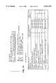
- FIG. 22gives datasheet descriptions of a new ISD register in the microcontroller and new ISD instructions for the microcontroller according to a preferred embodiment of the present invention.
- FIG. 23is a listing of an example program including debug capabilities according to a preferred embodiment of the present invention.
- FIG. 1is a flow diagram showing conventional steps in a general process for in-system programming.
- the general processincludes entering in-system programming mode 102, performing in-system programming 104, and exiting in-system programming mode 106.
- FIG. 2is a flow diagram showing a method 102 for entering in-system programming mode according to a preferred embodiment of the present invention.
- the method 102includes a first step 202 of sending a signal to turn-off an oscillator for the device to be programmed, a second step 204 of releasing a voltage on a second oscillator pin (OSC2), a third step 206 of applying a relatively high voltage to a first oscillator pin (OSC1) to enable EEPROM programming, and a fourth step 208 of turning-on an oscillator internal to the device to be programmed at a frequency corresponding to in-system programming cycles.
- OSC2second oscillator pin
- OSC1second oscillator pin
- OSC1first oscillator pin
- FIG. 3is a flow diagram showing a method 202 for sending a signal to turn-off an oscillator according to a preferred embodiment of the present invention.
- the method 202includes a first step 302 of driving a voltage on the first oscillator pin (OSC1) low, a second step 304 of driving a voltage on the second oscillator pin (OSC2) low, and a third step 306 of toggling a voltage between low and high multiple times.
- FIG. 4is a flow diagram showing a method 104 for performing in-system programming according to a preferred embodiment of the present invention.
- the method 104includes: a first step 402 of sending a synchronization cycle from the programming device to the device to be programmed; a second step 404 of sending multiple command cycles from the programming device to the device to be programmed; a third step 406 of either sending multiple data cycles from the programming device to the device to be programmed, or receiving multiple data cycles by the programming device from the device to be programmed; and a fourth step 408 of determining whether or not to continue programming. If it is determined in the fourth step 408 that programming is to be continued, then the method 104 loops back to perform the first step 402. Otherwise, if programming is not to be continued, then the method 104 terminates and in-system programming mode is then exited 106.
- FIG. 5is a flow diagram showing a method 106 for exiting in-system programming mode according to a preferred embodiment of the present invention.
- the method 106includes a first step 502 of driving a voltage on the first oscillator pin (OSC1) low, a second step 504 of waiting for a synchronization cycle to be sent from the programming device to the device to be programmed, and a third step 506 of resetting the device to be programmed and thus ending in-system programming mode.
- OSC1first oscillator pin
- FIG. 6is a diagram of a system for in-system programming of a microcontroller according to a preferred embodiment of the present invention.
- the systemincludes a system board 602 and an in-system programmer machine 610.
- the system board 602comprises a microcontroller 604, external oscillation circuitry 606, and a connector 608.
- the microcontroller 604includes two oscillator pins (OSC1 and OSC2) which couple to the external oscillation circuitry 606 and to the connector 608.
- the connector 608is further coupled to the in-system programmer 610.
- FIG. 7is a block diagram of a microcontroller 604 according to a preferred embodiment of the present invention.
- the microcontroller 604includes two oscillator pins (OSC1 and OSC2), an oscillator interface circuitry 702, in-system programming (ISP) circuitry 704, a central processing unit (CPU) 706, an electrically erasable programmable read-only memory (EEPROM) 708, internal oscillator circuitry 710, and input/output (I/O) ports 712.
- OSC1 and OSC2are coupled to the oscillator interface circuitry 702.
- the oscillator interface circuitry 702is further coupled to the ISP circuitry 704 and the CPU 706.
- the ISP circuitry 704is further coupled to the EEPROM 708 and the internal oscillator circuitry 710.
- the CPU 706is further coupled to the EEPROM 708, to the internal oscillator circuitry 710, and to the I/O ports 712 (which interface with circuitry outside the microcontroller 604 via I/O pins).
- conventional systemscouple their in-system programming circuitry to their input/output ports.
- FIGS. 8A, 8B, and 8Care circuit diagrams of conventional external oscillation circuits 606.
- FIG. 8Ais a circuit diagram of a conventional crystal oscillator circuit.
- the crystal oscillator (XTAL) circuitincludes a crystal 802 coupled between OSC1 and OSC2, a first capacitor 804 coupled between OSC1 and electrical ground, and a second capacitor 806 coupled between OSC2 and electrical ground.
- FIG. 8Bis a circuit diagram of a conventional external RC oscillator (XRC) circuit.
- the external RC oscillator circuitincludes a resistor 808 coupled between OSC1 and a power supply and a capacitor 810 coupled between OSC1 and electrical ground.
- FIG. 8Cshows that where an internal RC oscillator (IRC) circuit (i.e. one internal to the microcontroller chip) is used, no external oscillation circuit 606 is necessary.
- IRCinternal RC oscillator
- FIGS. 9A, 9B, and 9Care circuit diagrams of oscillator interface circuitry 702 in a microcontroller 604 according to a preferred embodiment of the present invention.
- FIG. 9Ais a circuit diagram of a first oscillator interface circuit for interfacing with a crystal oscillator circuit (XTAL).
- the first interface circuitincludes: a resistor 902 coupled between OSC1 and OSC2; an inverter 904 coupled between OSC1 and OSC2; a (NMOS) transistor with its source coupled to OSC1, its drain coupled to ground, and its gate coupled to a line for carrying a weak pull-down (weak -- pd) signal from the ISP circuitry 704.
- the first oscillator interface circuitalso couples OSC1 and OSC2 to the ISP circuitry 704 and the CPU 706.
- FIG. 9Bis a circuit diagram of a second oscillator interface circuit for interfacing with an external RC oscillator circuit (XRC).
- the second interface circuitincludes: a Schmitt trigger 908 with its input coupled to OSC1 and its output coupled to the CPU 706; and a (NMOS) transistor 910 with its source coupled to OSC1, its drain coupled to ground, and its gate coupled to the output of the trigger 908.
- the second interface circuitcouples OSC1 and OSC2 to the ISP circuitry 704.
- FIG. 9Cis a circuit diagram of a third oscillator interface circuit for the case when an internal RC oscillator (IRC) circuit is used.
- the third interface circuitincludes a NAND gate 912 with a first input coupled to OSC1, a second input coupled to ground, and an output coupled to the CPU 706. Because the second input is ground, the NAND gate 912 outputs high (logical 1) regardless of the first input. This is to prevent the output coupled to the CPU 706 from floating.
- the third interface circuitalso couples OSC1 and OSC2 to the ISP circuitry 704.
- microprocessor 604can implement all of the above three interface circuits 702 and use logic to activate the appropriate interface circuit depending on the external oscillator circuitry 606 chosen or being used. Implementing such logic is within the capabilities of one of ordinary skill in the pertinent art.
- FIGS. 10A, 10B, and 10Care timing diagrams of signals relating to the method for entering 102 in-system programming mode according to a preferred embodiment of the present invention.
- the timing diagram of FIG. 10Arelates to the case where a crystal oscillator (XTAL) is being used.
- the in-system programmer 610first sends 202 a signal to the microprocessor 604 to turn-off the crystal oscillator.
- the signalis sent 202 in three steps.
- the programmer 610interrupts the normal oscillation on OSC1 and OSC2 by driving and holding the voltage on OSC1 low. Since OSC2 is coupled to OSC1 via an inverter 904, when OSC1 is driven low, OSC2 goes high.
- the programmer 610drives the voltage on OSC2 low also, such that both OSC1 and OSC2 is low. This is an unusual condition given the inverter 904 between OSC1 and OSC2.
- the programmertoggles the voltage on OSC1 a plurality of times. More specifically, OSC1 goes from low to high and back to low nine (9) times. The ninth low-to-high transition (i.e. rising edge) of the voltage on OSC1 signals the microcontroller 604 to turn off its circuitry driving OSC1 and OSC2.
- the programmer 610releases 204 the voltage on OSC2 such that OSC2 is open drain, and then drives 206 the voltage on OSC1 to a rather high level (Vpp which is typically about 12.5 volts) to enable EEPROM programming.
- Vppwhich is typically about 12.5 volts
- the microprocessor 604turns-on 208 an internal oscillator 710 at a frequency (e.g., 128 KHz) for in-system programming.
- the timing diagram of FIG. 10Brelates to the case where an external RC oscillator (XRC) is being used.
- the in-system programmer 610first sends 202 a signal to the microprocessor 604 to turn-off the external oscillator.
- the signalis sent 202 in three steps.
- the programmer 610interrupts the normal oscillation on OSC1 and OSC2 by driving and holding the voltage on OSC1 low.
- the programmer 610drives the voltage on OSC2 low also, such that both OSC1 and OSC2 is low.
- the programmertoggles the voltage on OSC1 a plurality of times. More specifically, OSC1 goes from low to high and back to low nine (9) times.
- the ninth low-to-high transition (i.e. rising edge) of the voltage on OSC1signals the microcontroller 604 to turn off its circuitry driving OSC1 and OSC2. Thereafter, the programmer 610 releases 204 the voltage on OSC2 such that OSC2 is open drain, and then drives 206 the voltage on OSC1 to a rather high level (Vpp which is typically about 12.5 volts) to enable EEPROM programming. Finally, the microprocessor 604 turns-on 208 an internal oscillator 710 at a frequency (e.g., 128 KHz) for in-system programming Note that, as shown in FIG. 10B, the internal oscillator 710 may be turned on 208 after the ninth rising edge but before OSC1 is driven to Vpp.
- a frequencye.g., 128 KHz
- the timing diagram of FIG. 10Crelates to the case where an internal RC oscillator (IRC) is being used.
- the in-system programmer 610first sends 202 a signal to the microprocessor 604 to turn-off the normal oscillation of the internal oscillator 710.
- the signalis sent 202 in two steps.
- the programmer 610drives the voltage on OSC2 low also, such that both OSC1 and OSC2 is low (OSC1 begins low for the IRC case).
- the normal oscillationis allowed to toggle its voltage a plurality of times. More specifically, the normal oscillation goes from low to high and back to low nine (9) times.
- the ninth low-to-high transitioni.e.
- the microcontroller 604to turn off the normal oscillation of the internal oscillator 710. Thereafter, the programmer 610 releases 204 the voltage on OSC2 such that OSC2 is open drain, and then drives 206 the voltage on OSC1 to a rather high level (Vpp which is typically about 12.5 volts) to enable EEPROM programming. Finally, the microprocessor 604 turns-on 208 the internal oscillator 710 at a frequency (e.g., 128 KHz) for in-system programming.
- a frequencye.g., 128 KHz
- FIG. 11is a block diagram of in-system programming (ISP) circuitry 704 in a microcontroller 604 according to a preferred embodiment of the present invention.
- the ISP circuitry 704includes OSC1/OSC2 control circuitry 1102, a noise filter 1104, and EEPROM programming circuitry 1106.
- the OSC1/OSC2 control circuitry 1102is coupled to OSC1 and OSC2 (via the oscillator interface circuitry 702) and is also coupled to send the weak pull-down (weak -- pd) signal to the interface circuitry 702.
- the noise filter 1104is also coupled to OSC2 (via the interface circuitry 702) and is coupled to send a fall -- edge signal to the OSC1/OSC2 control circuitry 1102.
- the EEPROM programming circuitry 1106is also coupled to OSC2 (via the interface circuitry 702) and is further coupled to the EEPROM circuitry 708.
- programming circuitry 1106is coupled to send data to EEPROM IN of EEPROM circuitry 708, to receive data from EEPROM OUT of EEPROM circuitry 708, and to send commands via EEPROM CONTROL of EEPROM circuitry 708.
- FIG. 12is a circuit diagram of a noise filter 1104 in a microcontroller according to a preferred embodiment of the present invention.
- the noise filter 1104includes a first inverter 1202, a first AND gate 1204, a series of eight (8) D flip-flops 1206-1213, a second AND gate 1214, a ninth D flip-flop 1216, a second inverter 1218, and a third AND gate 1220.
- the first inverter 1202has its input coupled to OSC2 and its output coupled to a first input of the first AND gate 1204.
- a second input of the first AND gateis coupled to receive a reset signal (rst -- ).
- rst --is high.
- the voltage of rst --becomes low when the microcontroller 604 is reset.
- the noise filter 1104is effectively disabled since the output of the first AND gate 1204 is then low regardless of the output of the first inverter 1202.
- the output of the first AND gate 1204is coupled to the R (reset) input of the eight flip-flops 1206-1213 and to the R input of the ninth flip-flop 1216.
- Those nine flip-flops 1206-1213 and 1216are also coupled to receive a clock signal (clk).
- the clock signalis the signal on OSC1.
- the clock signalis the IRC clock signal.
- the first flip-flop 1206has its input (D) coupled to receive a power supply (high).
- the second through seventh flip-flops 1207-1212each has its input (D) coupled to receive the output (Q0-Q6, respectively) of the immediately prior sequential flip-flop (1206-1211, respectively).
- first through eighth flip-flops (1206-1213)each has its output (Q0-Q7, respectively) coupled to one of eight inputs to the second AND gate 1214.
- the second AND gate 1216has its output (Q70) coupled to the input (D) of the ninth flip-flop 1216 and to a first input of the third AND gate 1220.
- the ninth flip-flop 1216has its output (Q) coupled to an input of the second inverter 1218.
- the second inverter 1218has its output coupled to a second input of the third AND gate 1220.
- the third AND gate 1220outputs a signal designated fall -- edge.
- the fall -- edge signalindicates to the OSC1/OSC2 control circuitry (1102) that a signal has been sent 202 to turn-off the normal clock.
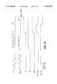
- FIG. 13is a timing diagram of signals in the noise filter according to a preferred embodiment of the present invention.
- the CLK signalcorresponds to the signal on OSC1 for the XTAL and XRC cases, and the IRC clock signal for the IRC case.
- the output of the noise filteris the fall -- edge signal.
- the OSC1/OSC2 control circuitryreceives the fall -- edge signal and causes an oscillator enable (OSC -- EN) signal to transition from high to low.
- OSC -- ENoscillator enable
- the falling edge of the OSC -- EN signaltriggers the OSC1/OSC2 control circuitry 1102 to release 204 the voltage on OSC2 and subsequently to drive 206 OSC1 to Vpp and cause the internal oscillator 710 to generate 208 a clock at the programming frequency (e.g., 128 KHz).
- the falling edge of the OSC -- EN signaltriggers the weak -- pd signal to go high, which temporarily pulls down the voltage on OSC1 before the voltage on OSC1 is driven to Vpp.
- FIG. 14is a diagram of EEPROM programming circuitry 1106 in the microcontroller 604 according to a preferred embodiment of the present invention.
- the programming circuitry 1106includes a trigger 1402, a first XOR gate 1404, encryption logic 1406, a data shift register 1408, a command shift register 1410, a command decode circuit 1412, a second XOR gate 1414, a transistor 1416, and a resistor 1418.
- the input of the trigger 1402has its input coupled to receive the signal on OSC2 and its output coupled to a first input of the first XOR gate 1404.
- the first XOR gate 1404has a second input coupled to receive an output from encryption logic 1406 and its output coupled to an input of a data shift register 1408 and an input of a command shift register 1410.
- the encryption logic 1406, the data shift register 1408, and the command shift register 1410are each coupled to receive a program clock from the internal oscillator 710.
- the program clockmay be, for example, at 128 KHz.
- the data shift register 1408has its output coupled to the EEPROM IN input of the EEPROM circuitry 708.
- the command shift register 1410has its output coupled to an input of the command decode circuit 1412.
- the command decode circuit 1412has its output coupled to the EEPROM CONTROL input of the EEPROM circuitry 708.
- the encryption logichas its output further coupled to a first input of the second XOR gate 1414.
- the second XOR gatehas another input coupled to receive data signals from the EEPROM OUT output of the EEPROM circuitry 708.
- the second XOR gatehas its output coupled to a gate of the transistor 1416.
- the transistor 1416has its source coupled to OSC2 and its drain coupled to ground.
- the resistor 1418is coupled between a power supply and OSC2.
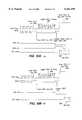
- FIG. 15is a timing diagram of the in-system programming protocol according to a preferred embodiment of the present invention.
- the protocolincludes frames.
- each frameincludes a synchronization (sync) cycle, four command cycles (so there can be up to 16 different ISP commands), and twelve data cycles (since the microcontroller being programmed uses 12-bit instruction words).
- Each cycleis as long as four (4) periods of the programming clock.
- the framebegins with a sync cycle. During the entire sync cycle (i.e. for all four clock periods), the voltage on OSC2 is high. In contrast, for each command or data cycle, the voltage on OSC2 is driven low during the second clock period (period 1) of the cycle.
- Each command cyclecorresponds to a bit transmitted from the programmer 610 to the microcontroller 604.
- Each data cyclecorresponds to a bit transmitted either (a) from the programmer 610 to the microcontroller 604, or (b) from the microcontroller 604 to the programmer 610.
- the command or data cyclerepresents a logical 1.
- the command or data cyclerepresents a logical 0.
- Samplingis performed at the edge between the third and fourth clock periods of each command or data cycle in order to determine the logical value.
- ISPIn-system programming
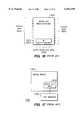
- FIG. 16is a diagram of a conventional bond-out microcontroller 1602.
- the bond-out microcontroller 1602is a special version of the microcontroller adapted for use in an in-circuit emulation (ICE) system.
- the bond-out microcontroller 1602includes both "normal" pins 1604 (i.e. those pins present in the production microcontroller) and extra "bond-out” pins 1606 that are bonded out from the data bus internal to the microcontroller 1602.
- the extra pins 1606are shown as being coupled to contents of a working (W) register of the microprocessor 1602. (Note the apparent location of the pins on the perimeter of the chip in FIG. 16 has no functional significance; the fact being illustrated is that there are extra pins.)
- FIG. 17is a diagram of a conventional in-circuit emulation (ICE) system 1700.
- the ICE system 1700includes a debug board 1702 and an ICE machine 1704.
- the debug board 1702is a special version of the system board adapted for use in an ICE system 1700.
- the debug board 1702includes the bond-out microcontroller 1602.
- the debug board 1702is coupled to the ICE machine 1704 via the extra pins 1606 of the bond-out microcontroller 1602.
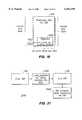
- FIG. 18is a diagram of a production microcontroller 604 with an in-system debugging (ISD) capability according to a preferred embodiment of the present invention.
- the microcontroller 604includes the "normal" pins 1604, but does not need extra "bond-out” pins 1606. As shown in FIG. 18, two of the normal pins 1604 are oscillator pins (OSC1 and OSC2).
- the microcontroller 604also includes registers 1802. As shown in FIG. 18, one of the registers 1802 is a working (W) register which is coupled to its carry (C) bit. The C bit is coupled to the OSC2 pin.
- Wworking
- Ccarry
- FIG. 19is a diagram of an in-system debugging (ISD) system 1900 according to a preferred embodiment of the present invention.
- the ISD system 1900includes a system board 602, a small ISD card 1904, and a computer system 1906.
- the system board 602includes the microcontroller 604 with an ISD capability and a connector 1908.
- the computer system 1906may be a personal computer system and includes an ISD software (S/W) module 1910.
- the microcontroller 604is coupled to the connector 1908.
- the connector 1908is coupled to the small ISD card 1904, and the small ISD card 1904 is coupled to the computer system 1906.
- the ISD capabilityis implemented by way of the oscillator pins.
- data for debuggingis communicated serially from the working (W) register to the ISD software 1910 via the carry (C) bit of the W register, the OSC2 pin, the small ISD card 1906, and the computer system 1906.
- the OSC2 pinis an open drain input/output with internal pull-up.
- the OSC1 pinis used to apply the programming voltage level (Vpp) necessary to program an EEPROM in the microcontroller 604.
- Vppprogramming voltage level
- FIG. 20is a diagram illustrating register stacks in the microcontroller 604 according to a preferred embodiment of the present invention.
- stacksincluding stacks for a working (W) register, a status register, a file select register, and a program counter (PC) register.
- the W registermay also be known as an accumulator register which is well known in the art.
- the status registerincludes various status flags such as the carry/borrow flags, a zero flag, a power down bit, and a time-out bit.
- the file select registeris a pointer for indirect addressing.
- the PC registerindicates the location of the instruction currently being processed.
- Each of the above register stacksare three stack addresses high 2002, 2004, and 2006.
- the top stack address 2002is the register itself (e.g., the W register).
- the middle stack address 2004contains the register contents last saved (i.e. by a push command).
- the lower stack address 2006contains the register contents previously saved (i.e. by two push commands).
- Three stack addresses 2002, 2004, and 2006are needed for each register stack because the state of the microcontroller 604 may need to be saved in two layers: first when a "normal" interrupts occurs, and second when a "debug" interrupt occurs. For example, consider the time before any interrupts when the top addresses 2002 of the above register stacks contain a "non-interrupt" state of the microcontroller 604.
- FIG. 21is a flow diagram of a method 2100 for in-system debugging according to a preferred embodiment of the present invention.
- the method 2100includes entering 102 in-system programming (ISP) mode 102, loading 2102 (via ISP 106) the EEPROM 708 with a program to be debugged, exiting 106 the ISP mode, and running 2104 the program while monitoring its execution via the in-system debugging (ISD) system.
- ISPin-system programming
- ISDin-system debugging
- said programcontains debug routines embedded therein, such as commands to add break points, to request single stepping, or to read registers.
- debug routinesembedded therein, such as commands to add break points, to request single stepping, or to read registers.
- exiting 106 ISP modenote that the microcontroller is reset at the end of the exiting 106.
- OSC1 and OSC2are monitored.
- the ISD circuits inside the microcontroller 604communicate to the ISD circuits outside the microcontroller 604 (external ISD circuits) by first driving and holding OSC2 low.
- OSC2is either (a) OSC2 is the inverse of OSC1 (for XTAL mode), or (b) OSC2 is pulled high by an internal pull-up resistor (for XRC or IRC modes).
- the external ISD circuitsdisables the clock circuitry on the system board 602 and takes control over providing a clock to the microcontroller 604 over OSC1.
- the external ISD circuitscan then shift out the register value serially over OSC2.
- FIG. 22gives datasheet descriptions of a new ISD register in the microcontroller 604 and new ISD instructions for the microcontroller 604 according to a preferred embodiment of the present invention.
- the new ISD registeris labeled DEBUG.
- the new ISD instructionsinclude OPTIONR, DEBUG, OSC2RW, SETBP, FIFO PUSH -- D, and POP -- D.
- FIG. 23is a listing of an example program including debug capabilities according to a preferred embodiment of the present invention. Instructions in the example program include "normal" microcontroller instructions and some of the new ISD instructions. The "normal" microcontroller instructions are described in various public documents, such as the book Easy PIC'n, by David Benson, published by Square 1 Electronics, 1996, said book is incorporated herein in its entirety. Creating such a program is within the capabilities of one of ordinary skill in the pertinent art.
- the first instruction executedis at address (hex) 7FF which instructs the microcontroller 604 to go to the instruction at address 040.
- the routine from 040 to 04Bsets a break point at 0C.
- such a break pointis not enabled (because the BRK -- EN bit of the DEBUG register is high).
- the microcontroller 604is instructed to return to user program at address 000.
- single-steppingis enabled (because the SS -- EN bit of the DEBUG register is low).
- a debug interruptis generated.
- the microcontroller 604is instructed to execute the instruction at address 7FE.
- the instruction at 7FEinstructs the microcontroller 604 to goto the instruction at 600, which is the first instruction of the debug interrupt service routine (debug ISR).
- debug ISRdebug interrupt service routine
- a "reti" instructionis used to exit the debug ISR. Control is then passed to the next instruction in the user program (e.g., the one at address 001).
Landscapes
- Engineering & Computer Science (AREA)
- Computer Hardware Design (AREA)
- Theoretical Computer Science (AREA)
- Quality & Reliability (AREA)
- Physics & Mathematics (AREA)
- General Engineering & Computer Science (AREA)
- General Physics & Mathematics (AREA)
- Microcomputers (AREA)
- Debugging And Monitoring (AREA)
Abstract
Description
Claims (20)
Priority Applications (2)
| Application Number | Priority Date | Filing Date | Title |
|---|---|---|---|
| US08/989,830US6161199A (en) | 1997-12-12 | 1997-12-12 | Non-intrusive in-system debugging for a microcontroller with in-system programming capabilities using in-system debugging circuitry and program embedded in-system debugging commands |
| PCT/US1998/026306WO1999031565A2 (en) | 1997-12-12 | 1998-12-10 | Method and apparatus for in-system debugging |
Applications Claiming Priority (1)
| Application Number | Priority Date | Filing Date | Title |
|---|---|---|---|
| US08/989,830US6161199A (en) | 1997-12-12 | 1997-12-12 | Non-intrusive in-system debugging for a microcontroller with in-system programming capabilities using in-system debugging circuitry and program embedded in-system debugging commands |
Publications (1)
| Publication Number | Publication Date |
|---|---|
| US6161199Atrue US6161199A (en) | 2000-12-12 |
Family
ID=25535504
Family Applications (1)
| Application Number | Title | Priority Date | Filing Date |
|---|---|---|---|
| US08/989,830Expired - Fee RelatedUS6161199A (en) | 1997-12-12 | 1997-12-12 | Non-intrusive in-system debugging for a microcontroller with in-system programming capabilities using in-system debugging circuitry and program embedded in-system debugging commands |
Country Status (2)
| Country | Link |
|---|---|
| US (1) | US6161199A (en) |
| WO (1) | WO1999031565A2 (en) |
Cited By (44)
| Publication number | Priority date | Publication date | Assignee | Title |
|---|---|---|---|---|
| US6360293B1 (en)* | 1998-06-24 | 2002-03-19 | Oki Electric Industry Co., Ltd. | Solid state disk system having electrically erasable and programmable read only memory |
| US6651199B1 (en)* | 2000-06-22 | 2003-11-18 | Xilinx, Inc. | In-system programmable flash memory device with trigger circuit for generating limited duration program instruction |
| US6681280B1 (en)* | 1998-10-29 | 2004-01-20 | Fujitsu Limited | Interrupt control apparatus and method separately holding respective operation information of a processor preceding a normal or a break interrupt |
| US6957180B1 (en)* | 2001-11-15 | 2005-10-18 | Cypress Semiconductor Corp. | System and a method for communication between an ICE and a production microcontroller while in a halt state |
| US7076420B1 (en)* | 2000-10-26 | 2006-07-11 | Cypress Semiconductor Corp. | Emulator chip/board architecture and interface |
| US7089175B1 (en)* | 2000-10-26 | 2006-08-08 | Cypress Semiconductor Corporation | Combined in-circuit emulator and programmer |
| US7526422B1 (en) | 2001-11-13 | 2009-04-28 | Cypress Semiconductor Corporation | System and a method for checking lock-step consistency between an in circuit emulation and a microcontroller |
| US7737724B2 (en) | 2007-04-17 | 2010-06-15 | Cypress Semiconductor Corporation | Universal digital block interconnection and channel routing |
| US7761845B1 (en) | 2002-09-09 | 2010-07-20 | Cypress Semiconductor Corporation | Method for parameterizing a user module |
| US7765095B1 (en) | 2000-10-26 | 2010-07-27 | Cypress Semiconductor Corporation | Conditional branching in an in-circuit emulation system |
| US7770113B1 (en) | 2001-11-19 | 2010-08-03 | Cypress Semiconductor Corporation | System and method for dynamically generating a configuration datasheet |
| US7774190B1 (en) | 2001-11-19 | 2010-08-10 | Cypress Semiconductor Corporation | Sleep and stall in an in-circuit emulation system |
| US7825688B1 (en) | 2000-10-26 | 2010-11-02 | Cypress Semiconductor Corporation | Programmable microcontroller architecture(mixed analog/digital) |
| US7844437B1 (en) | 2001-11-19 | 2010-11-30 | Cypress Semiconductor Corporation | System and method for performing next placements and pruning of disallowed placements for programming an integrated circuit |
| US7893724B2 (en) | 2004-03-25 | 2011-02-22 | Cypress Semiconductor Corporation | Method and circuit for rapid alignment of signals |
| US8026739B2 (en) | 2007-04-17 | 2011-09-27 | Cypress Semiconductor Corporation | System level interconnect with programmable switching |
| US8040266B2 (en) | 2007-04-17 | 2011-10-18 | Cypress Semiconductor Corporation | Programmable sigma-delta analog-to-digital converter |
| US8049569B1 (en) | 2007-09-05 | 2011-11-01 | Cypress Semiconductor Corporation | Circuit and method for improving the accuracy of a crystal-less oscillator having dual-frequency modes |
| US8069405B1 (en) | 2001-11-19 | 2011-11-29 | Cypress Semiconductor Corporation | User interface for efficiently browsing an electronic document using data-driven tabs |
| US8069436B2 (en) | 2004-08-13 | 2011-11-29 | Cypress Semiconductor Corporation | Providing hardware independence to automate code generation of processing device firmware |
| US8069428B1 (en) | 2001-10-24 | 2011-11-29 | Cypress Semiconductor Corporation | Techniques for generating microcontroller configuration information |
| US8067948B2 (en) | 2006-03-27 | 2011-11-29 | Cypress Semiconductor Corporation | Input/output multiplexer bus |
| US8078970B1 (en) | 2001-11-09 | 2011-12-13 | Cypress Semiconductor Corporation | Graphical user interface with user-selectable list-box |
| US8078894B1 (en) | 2007-04-25 | 2011-12-13 | Cypress Semiconductor Corporation | Power management architecture, method and configuration system |
| US8085067B1 (en) | 2005-12-21 | 2011-12-27 | Cypress Semiconductor Corporation | Differential-to-single ended signal converter circuit and method |
| US8085100B2 (en) | 2005-02-04 | 2011-12-27 | Cypress Semiconductor Corporation | Poly-phase frequency synthesis oscillator |
| US8089461B2 (en) | 2005-06-23 | 2012-01-03 | Cypress Semiconductor Corporation | Touch wake for electronic devices |
| US8092083B2 (en) | 2007-04-17 | 2012-01-10 | Cypress Semiconductor Corporation | Temperature sensor with digital bandgap |
| US8103497B1 (en) | 2002-03-28 | 2012-01-24 | Cypress Semiconductor Corporation | External interface for event architecture |
| US8103496B1 (en) | 2000-10-26 | 2012-01-24 | Cypress Semicondutor Corporation | Breakpoint control in an in-circuit emulation system |
| US8120408B1 (en) | 2005-05-05 | 2012-02-21 | Cypress Semiconductor Corporation | Voltage controlled oscillator delay cell and method |
| US8130025B2 (en) | 2007-04-17 | 2012-03-06 | Cypress Semiconductor Corporation | Numerical band gap |
| US8160864B1 (en) | 2000-10-26 | 2012-04-17 | Cypress Semiconductor Corporation | In-circuit emulator and pod synchronized boot |
| US8176296B2 (en) | 2000-10-26 | 2012-05-08 | Cypress Semiconductor Corporation | Programmable microcontroller architecture |
| US8286125B2 (en) | 2004-08-13 | 2012-10-09 | Cypress Semiconductor Corporation | Model for a hardware device-independent method of defining embedded firmware for programmable systems |
| US8402313B1 (en) | 2002-05-01 | 2013-03-19 | Cypress Semiconductor Corporation | Reconfigurable testing system and method |
| US8499270B1 (en) | 2007-04-25 | 2013-07-30 | Cypress Semiconductor Corporation | Configuration of programmable IC design elements |
| US8516025B2 (en) | 2007-04-17 | 2013-08-20 | Cypress Semiconductor Corporation | Clock driven dynamic datapath chaining |
| US8527949B1 (en) | 2001-11-19 | 2013-09-03 | Cypress Semiconductor Corporation | Graphical user interface for dynamically reconfiguring a programmable device |
| US9448964B2 (en) | 2009-05-04 | 2016-09-20 | Cypress Semiconductor Corporation | Autonomous control in a programmable system |
| US9564902B2 (en) | 2007-04-17 | 2017-02-07 | Cypress Semiconductor Corporation | Dynamically configurable and re-configurable data path |
| US9612987B2 (en) | 2009-05-09 | 2017-04-04 | Cypress Semiconductor Corporation | Dynamically reconfigurable analog routing circuits and methods for system on a chip |
| US9720805B1 (en) | 2007-04-25 | 2017-08-01 | Cypress Semiconductor Corporation | System and method for controlling a target device |
| US10698662B2 (en) | 2001-11-15 | 2020-06-30 | Cypress Semiconductor Corporation | System providing automatic source code generation for personalization and parameterization of user modules |
Citations (8)
| Publication number | Priority date | Publication date | Assignee | Title |
|---|---|---|---|---|
| US4727514A (en)* | 1986-02-11 | 1988-02-23 | Texas Instruments Incorporated | Programmable memory with memory cells programmed by addressing |
| US5157781A (en)* | 1990-01-02 | 1992-10-20 | Motorola, Inc. | Data processor test architecture |
| US5278759A (en)* | 1991-05-07 | 1994-01-11 | Chrysler Corporation | System and method for reprogramming vehicle computers |
| US5473758A (en)* | 1992-08-31 | 1995-12-05 | Microchip Technology Incorporated | System having input output pins shifting between programming mode and normal mode to program memory without dedicating input output pins for programming mode |
| US5686844A (en)* | 1996-05-24 | 1997-11-11 | Microchip Technology Incorporated | Integrated circuit pins configurable as a clock input pin and as a digital I/O pin or as a device reset pin and as a digital I/O pin and method therefor |
| US5790833A (en)* | 1992-07-21 | 1998-08-04 | Advanced Micro Devices, Inc. | Integrated circuit, having microprocessor and telephony peripheral circuitry, having capability of being placed in partial emulation mode |
| US5841996A (en)* | 1995-10-13 | 1998-11-24 | Microchip Technology Incorporated | Serial communication interface system having programmable microcontroller for use in a battery pack |
| US5903718A (en)* | 1996-09-16 | 1999-05-11 | International Business Machines Corporation | Remote program monitor method and system using a system-under-test microcontroller for self-debug |
- 1997
- 1997-12-12USUS08/989,830patent/US6161199A/ennot_activeExpired - Fee Related
- 1998
- 1998-12-10WOPCT/US1998/026306patent/WO1999031565A2/enactiveApplication Filing
Patent Citations (8)
| Publication number | Priority date | Publication date | Assignee | Title |
|---|---|---|---|---|
| US4727514A (en)* | 1986-02-11 | 1988-02-23 | Texas Instruments Incorporated | Programmable memory with memory cells programmed by addressing |
| US5157781A (en)* | 1990-01-02 | 1992-10-20 | Motorola, Inc. | Data processor test architecture |
| US5278759A (en)* | 1991-05-07 | 1994-01-11 | Chrysler Corporation | System and method for reprogramming vehicle computers |
| US5790833A (en)* | 1992-07-21 | 1998-08-04 | Advanced Micro Devices, Inc. | Integrated circuit, having microprocessor and telephony peripheral circuitry, having capability of being placed in partial emulation mode |
| US5473758A (en)* | 1992-08-31 | 1995-12-05 | Microchip Technology Incorporated | System having input output pins shifting between programming mode and normal mode to program memory without dedicating input output pins for programming mode |
| US5841996A (en)* | 1995-10-13 | 1998-11-24 | Microchip Technology Incorporated | Serial communication interface system having programmable microcontroller for use in a battery pack |
| US5686844A (en)* | 1996-05-24 | 1997-11-11 | Microchip Technology Incorporated | Integrated circuit pins configurable as a clock input pin and as a digital I/O pin or as a device reset pin and as a digital I/O pin and method therefor |
| US5903718A (en)* | 1996-09-16 | 1999-05-11 | International Business Machines Corporation | Remote program monitor method and system using a system-under-test microcontroller for self-debug |
Non-Patent Citations (2)
| Title |
|---|
| Easy Pic n, A Beginner s Guide to Using PIC 16/17 Microcontrollers; Square 1 Electronics David Benson, Version 2.0; pp. 1 153.* |
| Easy Pic'n, A Beginner's Guide to Using PIC 16/17 Microcontrollers; Square 1 Electronics--David Benson, Version 2.0; pp. 1-153. |
Cited By (64)
| Publication number | Priority date | Publication date | Assignee | Title |
|---|---|---|---|---|
| US6360293B1 (en)* | 1998-06-24 | 2002-03-19 | Oki Electric Industry Co., Ltd. | Solid state disk system having electrically erasable and programmable read only memory |
| US6681280B1 (en)* | 1998-10-29 | 2004-01-20 | Fujitsu Limited | Interrupt control apparatus and method separately holding respective operation information of a processor preceding a normal or a break interrupt |
| US7581090B2 (en) | 1999-10-29 | 2009-08-25 | Fujitsu Limited | Interrupt control apparatus and method |
| US20040088462A1 (en)* | 1999-10-29 | 2004-05-06 | Fujitsu Limited | Interrupt control apparatus and method |
| US6651199B1 (en)* | 2000-06-22 | 2003-11-18 | Xilinx, Inc. | In-system programmable flash memory device with trigger circuit for generating limited duration program instruction |
| US8160864B1 (en) | 2000-10-26 | 2012-04-17 | Cypress Semiconductor Corporation | In-circuit emulator and pod synchronized boot |
| US7825688B1 (en) | 2000-10-26 | 2010-11-02 | Cypress Semiconductor Corporation | Programmable microcontroller architecture(mixed analog/digital) |
| US8176296B2 (en) | 2000-10-26 | 2012-05-08 | Cypress Semiconductor Corporation | Programmable microcontroller architecture |
| US7076420B1 (en)* | 2000-10-26 | 2006-07-11 | Cypress Semiconductor Corp. | Emulator chip/board architecture and interface |
| US10725954B2 (en) | 2000-10-26 | 2020-07-28 | Monterey Research, Llc | Microcontroller programmable system on a chip |
| US10020810B2 (en) | 2000-10-26 | 2018-07-10 | Cypress Semiconductor Corporation | PSoC architecture |
| US7765095B1 (en) | 2000-10-26 | 2010-07-27 | Cypress Semiconductor Corporation | Conditional branching in an in-circuit emulation system |
| US8149048B1 (en) | 2000-10-26 | 2012-04-03 | Cypress Semiconductor Corporation | Apparatus and method for programmable power management in a programmable analog circuit block |
| US8103496B1 (en) | 2000-10-26 | 2012-01-24 | Cypress Semicondutor Corporation | Breakpoint control in an in-circuit emulation system |
| US7089175B1 (en)* | 2000-10-26 | 2006-08-08 | Cypress Semiconductor Corporation | Combined in-circuit emulator and programmer |
| US8555032B2 (en) | 2000-10-26 | 2013-10-08 | Cypress Semiconductor Corporation | Microcontroller programmable system on a chip with programmable interconnect |
| US8358150B1 (en) | 2000-10-26 | 2013-01-22 | Cypress Semiconductor Corporation | Programmable microcontroller architecture(mixed analog/digital) |
| US8736303B2 (en) | 2000-10-26 | 2014-05-27 | Cypress Semiconductor Corporation | PSOC architecture |
| US9766650B2 (en) | 2000-10-26 | 2017-09-19 | Cypress Semiconductor Corporation | Microcontroller programmable system on a chip with programmable interconnect |
| US10261932B2 (en) | 2000-10-26 | 2019-04-16 | Cypress Semiconductor Corporation | Microcontroller programmable system on a chip |
| US9843327B1 (en) | 2000-10-26 | 2017-12-12 | Cypress Semiconductor Corporation | PSOC architecture |
| US10248604B2 (en) | 2000-10-26 | 2019-04-02 | Cypress Semiconductor Corporation | Microcontroller programmable system on a chip |
| US10466980B2 (en) | 2001-10-24 | 2019-11-05 | Cypress Semiconductor Corporation | Techniques for generating microcontroller configuration information |
| US8069428B1 (en) | 2001-10-24 | 2011-11-29 | Cypress Semiconductor Corporation | Techniques for generating microcontroller configuration information |
| US8793635B1 (en) | 2001-10-24 | 2014-07-29 | Cypress Semiconductor Corporation | Techniques for generating microcontroller configuration information |
| US8078970B1 (en) | 2001-11-09 | 2011-12-13 | Cypress Semiconductor Corporation | Graphical user interface with user-selectable list-box |
| US7526422B1 (en) | 2001-11-13 | 2009-04-28 | Cypress Semiconductor Corporation | System and a method for checking lock-step consistency between an in circuit emulation and a microcontroller |
| US6957180B1 (en)* | 2001-11-15 | 2005-10-18 | Cypress Semiconductor Corp. | System and a method for communication between an ICE and a production microcontroller while in a halt state |
| US10698662B2 (en) | 2001-11-15 | 2020-06-30 | Cypress Semiconductor Corporation | System providing automatic source code generation for personalization and parameterization of user modules |
| US7774190B1 (en) | 2001-11-19 | 2010-08-10 | Cypress Semiconductor Corporation | Sleep and stall in an in-circuit emulation system |
| US7844437B1 (en) | 2001-11-19 | 2010-11-30 | Cypress Semiconductor Corporation | System and method for performing next placements and pruning of disallowed placements for programming an integrated circuit |
| US8533677B1 (en) | 2001-11-19 | 2013-09-10 | Cypress Semiconductor Corporation | Graphical user interface for dynamically reconfiguring a programmable device |
| US8527949B1 (en) | 2001-11-19 | 2013-09-03 | Cypress Semiconductor Corporation | Graphical user interface for dynamically reconfiguring a programmable device |
| US7770113B1 (en) | 2001-11-19 | 2010-08-03 | Cypress Semiconductor Corporation | System and method for dynamically generating a configuration datasheet |
| US8370791B2 (en) | 2001-11-19 | 2013-02-05 | Cypress Semiconductor Corporation | System and method for performing next placements and pruning of disallowed placements for programming an integrated circuit |
| US8069405B1 (en) | 2001-11-19 | 2011-11-29 | Cypress Semiconductor Corporation | User interface for efficiently browsing an electronic document using data-driven tabs |
| US8103497B1 (en) | 2002-03-28 | 2012-01-24 | Cypress Semiconductor Corporation | External interface for event architecture |
| US8402313B1 (en) | 2002-05-01 | 2013-03-19 | Cypress Semiconductor Corporation | Reconfigurable testing system and method |
| US7761845B1 (en) | 2002-09-09 | 2010-07-20 | Cypress Semiconductor Corporation | Method for parameterizing a user module |
| US7893724B2 (en) | 2004-03-25 | 2011-02-22 | Cypress Semiconductor Corporation | Method and circuit for rapid alignment of signals |
| US8069436B2 (en) | 2004-08-13 | 2011-11-29 | Cypress Semiconductor Corporation | Providing hardware independence to automate code generation of processing device firmware |
| US8286125B2 (en) | 2004-08-13 | 2012-10-09 | Cypress Semiconductor Corporation | Model for a hardware device-independent method of defining embedded firmware for programmable systems |
| US8539398B2 (en) | 2004-08-13 | 2013-09-17 | Cypress Semiconductor Corporation | Model for a hardware device-independent method of defining embedded firmware for programmable systems |
| US8085100B2 (en) | 2005-02-04 | 2011-12-27 | Cypress Semiconductor Corporation | Poly-phase frequency synthesis oscillator |
| US8120408B1 (en) | 2005-05-05 | 2012-02-21 | Cypress Semiconductor Corporation | Voltage controlled oscillator delay cell and method |
| US8089461B2 (en) | 2005-06-23 | 2012-01-03 | Cypress Semiconductor Corporation | Touch wake for electronic devices |
| US8085067B1 (en) | 2005-12-21 | 2011-12-27 | Cypress Semiconductor Corporation | Differential-to-single ended signal converter circuit and method |
| US8067948B2 (en) | 2006-03-27 | 2011-11-29 | Cypress Semiconductor Corporation | Input/output multiplexer bus |
| US8717042B1 (en) | 2006-03-27 | 2014-05-06 | Cypress Semiconductor Corporation | Input/output multiplexer bus |
| US8476928B1 (en) | 2007-04-17 | 2013-07-02 | Cypress Semiconductor Corporation | System level interconnect with programmable switching |
| US8092083B2 (en) | 2007-04-17 | 2012-01-10 | Cypress Semiconductor Corporation | Temperature sensor with digital bandgap |
| US8130025B2 (en) | 2007-04-17 | 2012-03-06 | Cypress Semiconductor Corporation | Numerical band gap |
| US8040266B2 (en) | 2007-04-17 | 2011-10-18 | Cypress Semiconductor Corporation | Programmable sigma-delta analog-to-digital converter |
| US7737724B2 (en) | 2007-04-17 | 2010-06-15 | Cypress Semiconductor Corporation | Universal digital block interconnection and channel routing |
| US9564902B2 (en) | 2007-04-17 | 2017-02-07 | Cypress Semiconductor Corporation | Dynamically configurable and re-configurable data path |
| US8026739B2 (en) | 2007-04-17 | 2011-09-27 | Cypress Semiconductor Corporation | System level interconnect with programmable switching |
| US8516025B2 (en) | 2007-04-17 | 2013-08-20 | Cypress Semiconductor Corporation | Clock driven dynamic datapath chaining |
| US8909960B1 (en) | 2007-04-25 | 2014-12-09 | Cypress Semiconductor Corporation | Power management architecture, method and configuration system |
| US8499270B1 (en) | 2007-04-25 | 2013-07-30 | Cypress Semiconductor Corporation | Configuration of programmable IC design elements |
| US8078894B1 (en) | 2007-04-25 | 2011-12-13 | Cypress Semiconductor Corporation | Power management architecture, method and configuration system |
| US9720805B1 (en) | 2007-04-25 | 2017-08-01 | Cypress Semiconductor Corporation | System and method for controlling a target device |
| US8049569B1 (en) | 2007-09-05 | 2011-11-01 | Cypress Semiconductor Corporation | Circuit and method for improving the accuracy of a crystal-less oscillator having dual-frequency modes |
| US9448964B2 (en) | 2009-05-04 | 2016-09-20 | Cypress Semiconductor Corporation | Autonomous control in a programmable system |
| US9612987B2 (en) | 2009-05-09 | 2017-04-04 | Cypress Semiconductor Corporation | Dynamically reconfigurable analog routing circuits and methods for system on a chip |
Also Published As
| Publication number | Publication date |
|---|---|
| WO1999031565A2 (en) | 1999-06-24 |
| WO1999031565A3 (en) | 1999-08-19 |
Similar Documents
| Publication | Publication Date | Title |
|---|---|---|
| US6161199A (en) | Non-intrusive in-system debugging for a microcontroller with in-system programming capabilities using in-system debugging circuitry and program embedded in-system debugging commands | |
| US4939637A (en) | Circuitry for producing emulation mode in single chip microcomputer | |
| US6957180B1 (en) | System and a method for communication between an ICE and a production microcontroller while in a halt state | |
| US5966723A (en) | Serial programming mode for non-volatile memory | |
| US5630102A (en) | In-circuit-emulation event management system | |
| US6845027B2 (en) | Semiconductor chip | |
| US5566303A (en) | Microcomputer with multiple CPU'S on a single chip with provision for testing and emulation of sub CPU's | |
| US4870562A (en) | Microcomputer capable of accessing internal memory at a desired variable access time | |
| US20070006035A1 (en) | Microcomputer and method for developing system program | |
| US8732526B1 (en) | Single-wire data interface for programming, debugging and testing a programmable element | |
| US6978322B2 (en) | Embedded controller for real-time backup of operation states of peripheral devices | |
| US20090204779A1 (en) | Controlling embedded memory access | |
| CN101267623A (en) | A booting construction method for a mobile phone | |
| WO2022237486A1 (en) | Chip having interface multiplexing function and debugging system of chip | |
| US7013409B2 (en) | Method and apparatus for debugging a data processing system | |
| US6021447A (en) | Non-intrusive in-system programming using in-system programming circuitry coupled to oscillation circuitry for entering, exiting, and performing in-system programming responsive to oscillation circuitry signals | |
| US4809167A (en) | Circuitry for emulating single chip microcomputer without access to internal buses | |
| JP4504466B2 (en) | Method for performing communication within a computer system | |
| US6877113B2 (en) | Break determining circuit for a debugging support unit in a semiconductor integrated circuit | |
| JP2743850B2 (en) | Data processing device | |
| US7107489B2 (en) | Method and apparatus for debugging a data processing system | |
| US5995993A (en) | Serial in-circuit emulator | |
| JPS6360424B2 (en) | ||
| US7945718B2 (en) | Microcontroller waveform generation | |
| US7437616B2 (en) | Dual CPU on-chip-debug low-gate-count architecture with real-time-data tracing |
Legal Events
| Date | Code | Title | Description |
|---|---|---|---|
| AS | Assignment | Owner name:SCENIX SEMICONDUCTOR, INC., CALIFORNIA Free format text:ASSIGNMENT OF ASSIGNORS INTEREST;ASSIGNORS:SZETO, KINYUE;GRACEY III, CHARLES M.;CHENG, CHUCK CHEUK-WING;REEL/FRAME:009107/0245;SIGNING DATES FROM 19971203 TO 19980316 | |
| AS | Assignment | Owner name:SILICON VALLEY BANK, CALIFORNIA Free format text:SECURITY AGREEMENT;ASSIGNOR:SCENIX SEMICONDUCTOR, INC.;REEL/FRAME:009694/0392 Effective date:19980916 | |
| FEPP | Fee payment procedure | Free format text:PAYOR NUMBER ASSIGNED (ORIGINAL EVENT CODE: ASPN); ENTITY STATUS OF PATENT OWNER: SMALL ENTITY | |
| CC | Certificate of correction | ||
| AS | Assignment | Owner name:CHIP TRUST III, THE, CALIFORNIA Free format text:ASSIGNMENT OF ASSIGNORS INTEREST;ASSIGNOR:UBICOM, INC.;REEL/FRAME:014438/0923 Effective date:20030826 Owner name:JATOTECH AFFILIATES, L.P., TEXAS Free format text:ASSIGNMENT OF ASSIGNORS INTEREST;ASSIGNOR:UBICOM, INC.;REEL/FRAME:014438/0923 Effective date:20030826 Owner name:JATOTECH VENTURES, L.P., TEXAS Free format text:ASSIGNMENT OF ASSIGNORS INTEREST;ASSIGNOR:UBICOM, INC.;REEL/FRAME:014438/0923 Effective date:20030826 Owner name:MAYFIELD ASSOCIATES FUND IV, CALIFORNIA Free format text:ASSIGNMENT OF ASSIGNORS INTEREST;ASSIGNOR:UBICOM, INC.;REEL/FRAME:014438/0923 Effective date:20030826 Owner name:MAYFIELD ASSOCIATES FUND VI, CALIFORNIA Free format text:ASSIGNMENT OF ASSIGNORS INTEREST;ASSIGNOR:UBICOM, INC.;REEL/FRAME:014438/0923 Effective date:20030826 Owner name:MAYFIELD IX, CALIFORNIA Free format text:ASSIGNMENT OF ASSIGNORS INTEREST;ASSIGNOR:UBICOM, INC.;REEL/FRAME:014438/0923 Effective date:20030826 Owner name:MAYFIELD PRINCIPALS FUND II, CALIFORNIA Free format text:ASSIGNMENT OF ASSIGNORS INTEREST;ASSIGNOR:UBICOM, INC.;REEL/FRAME:014438/0923 Effective date:20030826 Owner name:MAYFIELD XI QUALIFIED, CALIFORNIA Free format text:ASSIGNMENT OF ASSIGNORS INTEREST;ASSIGNOR:UBICOM, INC.;REEL/FRAME:014438/0923 Effective date:20030826 Owner name:MAYFIELD XI, CALIFORNIA Free format text:ASSIGNMENT OF ASSIGNORS INTEREST;ASSIGNOR:UBICOM, INC.;REEL/FRAME:014438/0923 Effective date:20030826 Owner name:UNGER-LUCHSINGER FAMILY TRUST, THE, CALIFORNIA Free format text:ASSIGNMENT OF ASSIGNORS INTEREST;ASSIGNOR:UBICOM, INC.;REEL/FRAME:014438/0923 Effective date:20030826 | |
| FPAY | Fee payment | Year of fee payment:4 | |
| AS | Assignment | Owner name:SILICON VALLEY BANK INC., CALIFORNIA Free format text:SECURITY AGREEMENT;ASSIGNOR:UBICOM, INC.;REEL/FRAME:019193/0350 Effective date:20070327 | |
| REMI | Maintenance fee reminder mailed | ||
| FEPP | Fee payment procedure | Free format text:PAYER NUMBER DE-ASSIGNED (ORIGINAL EVENT CODE: RMPN); ENTITY STATUS OF PATENT OWNER: SMALL ENTITY | |
| LAPS | Lapse for failure to pay maintenance fees | ||
| STCH | Information on status: patent discontinuation | Free format text:PATENT EXPIRED DUE TO NONPAYMENT OF MAINTENANCE FEES UNDER 37 CFR 1.362 | |
| FP | Lapsed due to failure to pay maintenance fee | Effective date:20081212 | |
| AS | Assignment | Owner name:UBICOM, INC., CALIFORNIA Free format text:RELEASE;ASSIGNOR:SILICON VALLEY BANK;REEL/FRAME:027762/0163 Effective date:20120221 | |
| AS | Assignment | Owner name:UBICOM (ASSIGNMENT FOR THE BENEFIT OF CREDITORS), Free format text:ASSIGNMENT OF ASSIGNORS INTEREST;ASSIGNOR:UBICOM, INC.;REEL/FRAME:027830/0061 Effective date:20120217 | |
| AS | Assignment | Owner name:QUALCOMM ATHEROS, INC., CALIFORNIA Free format text:ASSIGNMENT OF ASSIGNORS INTEREST;ASSIGNOR:UBICOM (ASSIGNMENT FOR THE BENEFIT OF CREDITORS), LLC;REEL/FRAME:027833/0926 Effective date:20120217 | |
| AS | Assignment | Owner name:UBICOM, INC., CALIFORNIA Free format text:CHANGE OF NAME;ASSIGNOR:SCENIX SEMICONDUCTOR, INC.;REEL/FRAME:028222/0394 Effective date:20001208 | |
| AS | Assignment | Owner name:QUALCOMM INCORPORATED, CALIFORNIA Free format text:ASSIGNMENT OF ASSIGNORS INTEREST;ASSIGNOR:QUALCOMM ATHEROS, INC.;REEL/FRAME:045169/0031 Effective date:20121022 |