US6161160A - Network interface device architecture for storing transmit and receive data in a random access buffer memory across independent clock domains - Google Patents
Network interface device architecture for storing transmit and receive data in a random access buffer memory across independent clock domainsDownload PDFInfo
- Publication number
- US6161160A US6161160AUS09/146,163US14616398AUS6161160AUS 6161160 AUS6161160 AUS 6161160AUS 14616398 AUS14616398 AUS 14616398AUS 6161160 AUS6161160 AUS 6161160A
- Authority
- US
- United States
- Prior art keywords
- data
- transmit
- receive
- random access
- buffer
- Prior art date
- Legal status (The legal status is an assumption and is not a legal conclusion. Google has not performed a legal analysis and makes no representation as to the accuracy of the status listed.)
- Expired - Lifetime
Links
- 239000000872bufferSubstances0.000titleclaimsabstractdescription142
- 230000015654memoryEffects0.000titleclaimsabstractdescription100
- 238000012546transferMethods0.000claimsabstractdescription61
- 230000004044responseEffects0.000claimsabstractdescription48
- 230000005540biological transmissionEffects0.000claimsabstractdescription14
- 238000000034methodMethods0.000claimsdescription27
- 238000012544monitoring processMethods0.000claimsdescription27
- 238000010586diagramMethods0.000description19
- 230000001360synchronised effectEffects0.000description12
- 230000003139buffering effectEffects0.000description3
- 238000001514detection methodMethods0.000description3
- 230000007704transitionEffects0.000description3
- 230000000694effectsEffects0.000description2
- 230000006870functionEffects0.000description2
- 230000000977initiatory effectEffects0.000description2
- 230000002093peripheral effectEffects0.000description2
- 230000002411adverseEffects0.000description1
- 238000004891communicationMethods0.000description1
- 238000013461designMethods0.000description1
- 239000012634fragmentSubstances0.000description1
- 230000006386memory functionEffects0.000description1
- 238000012986modificationMethods0.000description1
- 230000004048modificationEffects0.000description1
- 238000012856packingMethods0.000description1
- 230000008569processEffects0.000description1
- 238000011084recoveryMethods0.000description1
- 230000009467reductionEffects0.000description1
- 238000012360testing methodMethods0.000description1
- 238000010977unit operationMethods0.000description1
Images


Classifications
- H—ELECTRICITY
- H04—ELECTRIC COMMUNICATION TECHNIQUE
- H04L—TRANSMISSION OF DIGITAL INFORMATION, e.g. TELEGRAPHIC COMMUNICATION
- H04L12/00—Data switching networks
- H04L12/28—Data switching networks characterised by path configuration, e.g. LAN [Local Area Networks] or WAN [Wide Area Networks]
- H04L12/40—Bus networks
- H04L12/40006—Architecture of a communication node
- H04L12/40032—Details regarding a bus interface enhancer
- H—ELECTRICITY
- H04—ELECTRIC COMMUNICATION TECHNIQUE
- H04L—TRANSMISSION OF DIGITAL INFORMATION, e.g. TELEGRAPHIC COMMUNICATION
- H04L12/00—Data switching networks
- H04L12/28—Data switching networks characterised by path configuration, e.g. LAN [Local Area Networks] or WAN [Wide Area Networks]
- H04L12/40—Bus networks
- H04L12/407—Bus networks with decentralised control
- H04L12/413—Bus networks with decentralised control with random access, e.g. carrier-sense multiple-access with collision detection [CSMA-CD]
- H—ELECTRICITY
- H04—ELECTRIC COMMUNICATION TECHNIQUE
- H04L—TRANSMISSION OF DIGITAL INFORMATION, e.g. TELEGRAPHIC COMMUNICATION
- H04L12/00—Data switching networks
- H04L12/54—Store-and-forward switching systems
- H04L12/56—Packet switching systems
- H—ELECTRICITY
- H04—ELECTRIC COMMUNICATION TECHNIQUE
- H04L—TRANSMISSION OF DIGITAL INFORMATION, e.g. TELEGRAPHIC COMMUNICATION
- H04L49/00—Packet switching elements
- H04L49/90—Buffering arrangements
- H—ELECTRICITY
- H04—ELECTRIC COMMUNICATION TECHNIQUE
- H04L—TRANSMISSION OF DIGITAL INFORMATION, e.g. TELEGRAPHIC COMMUNICATION
- H04L49/00—Packet switching elements
- H04L49/90—Buffering arrangements
- H04L49/901—Buffering arrangements using storage descriptor, e.g. read or write pointers
- H—ELECTRICITY
- H04—ELECTRIC COMMUNICATION TECHNIQUE
- H04L—TRANSMISSION OF DIGITAL INFORMATION, e.g. TELEGRAPHIC COMMUNICATION
- H04L49/00—Packet switching elements
- H04L49/90—Buffering arrangements
- H04L49/9063—Intermediate storage in different physical parts of a node or terminal
- H—ELECTRICITY
- H04—ELECTRIC COMMUNICATION TECHNIQUE
- H04L—TRANSMISSION OF DIGITAL INFORMATION, e.g. TELEGRAPHIC COMMUNICATION
- H04L49/00—Packet switching elements
- H04L49/90—Buffering arrangements
- H04L49/9084—Reactions to storage capacity overflow
- H04L49/9089—Reactions to storage capacity overflow replacing packets in a storage arrangement, e.g. pushout
- H—ELECTRICITY
- H04—ELECTRIC COMMUNICATION TECHNIQUE
- H04L—TRANSMISSION OF DIGITAL INFORMATION, e.g. TELEGRAPHIC COMMUNICATION
- H04L7/00—Arrangements for synchronising receiver with transmitter
- H04L7/02—Speed or phase control by the received code signals, the signals containing no special synchronisation information
Definitions
- the present inventionrelates to network interfacing and more particularly, to methods and systems for buffering data between a host bus interface and a media access controller accessing Ethernet (IEEE 802.3) media.
- IEEE 802.3media access controller accessing Ethernet
- Network interface deviceshandle packets of data for transmission between a host computer and a network communications system, such as a local area network.
- the host computermay be implemented as a client station, a server, or a switched hub.
- One primary function of the network interface deviceis to buffer data to compensate for timing discrepancies between the clock domain of the host computer and the clock domain of the network.
- Network interface devicestypically include a first in, first out (FIFO) buffer memory for storing transmit and receive data, where the transmit data is stored in a transmit FIFO prior to transmission on the network media by the MAC, and receive data is stored in a receive FIFO by the MAC prior to transfer to the host computer via the host computer bus interface.
- FIFOfirst in, first out
- the latency of the network interface deviceis the time delay between the time that a data frame is supplied to the network interface device and the time the data is transmitted on the network media, or vice versa.
- a FIFO for transmit buffer or receive bufferAn additional disadvantage with the use of a FIFO for transmit buffer or receive buffer is the increasing complexity associated with maintaining status information for each data frame stored in the FIFO buffer. If a stored data frame is to have corresponding status information, then an additional FIFO buffer would be required for storing the status information for each stored data frame. Hence, a transmit buffer may require a data frame FIFO for the actual frame data, and a status FIFO for storing the corresponding status information for each data frame. Such an arrangement would result in a substantial increase in the amount of area required on a chip for the status FIFO. In addition, additional synchronization logic would be required to maintain correspondence between the stored frame data and the corresponding status data, increasing the cost and complexity of the network interface device.
- buffer overflowcan occur when the time domains between the host bus and the network media are uncontrollable to the extent that data is stored in the buffer at a rate faster than the data can be removed, resulting in an overflow situation.
- underflowoccurs if data is removed from the FIFO buffer faster than the data can be supplied.
- a FIFOas a transmit buffer or receive buffer
- the media access controllerreceives a runt packet from the network (i.e., an invalid packet less than the minimum required frame size of 64 bytes)
- the MACcannot cause the invalid data stored in the FIFO to be flushed, without eliminating the entire contents of the receive FIFO.
- the invalid datais transferred via the host computer bus and stored in host computer memory, before the host computer can determine that the transferred data is invalid.
- the reduction in throughputmay have substantial effects, especially in full-duplex networks, where the host computer bus is heavily utilized by the network interface device for simultaneous transmission and reception of data frames on the network medium.
- An additional problem encountered with conventional network interface devicesis the latency encountered during host bus transfers.
- two types of bus transfersmay be used, namely master mode and slave mode.
- master modethe network interface device operates as a master, and initiates the transfer of data across the host bus by requesting use of the bus, and then transferring the data as a data burst.
- a host busis the peripheral component interconnect (PCI) local bus, where a transfer of data over a PCI bus includes an address phase followed by one or more contiguous data phases.
- PCIperipheral component interconnect
- the PCI bus protocolmakes use of a centralized, synchronous arbitration scheme in which each PCI master must arbitrate for each transaction by use of a request signal and a grant signal.
- a network interface device having data to transferwill assert a request signal to request use of the bus.
- a host CPUwill respond with a grant signal which is followed by assertion of a frame signal that together identify when the bus is available for use by the network interface.
- An additional problem with conventional network interface devicesis the occurrence of wait states encountered during a complex bus termination condition, where certain events on the PCI bus forcibly halt a PCI bus data transfer.
- Two examples of complex conditionsinclude when a host memory is not ready to receive a data transfer after the bus has been secured, or when the host memory becomes unable to continue receiving data following initiation of the data transfer. In either case, the target asserts a STOP# signal on the PCI bus to terminate the data transfer.
- Prior art systemsfrequently lose data from the FIFO buffer memory in response to encountering such complex conditions, for example retry or disconnect states. Hence, complicated recovery arrangements are conventionally required in prior art systems to mitigate the loss of data. For example, higher network protocol layers may need to send a message across the network, requesting the transmitting station to resend a data packet.
- a network interface architectureasynchronously monitors the status of data stored in a random access transmit buffer and a random access receive buffer to enable multiple memory controllers to store and read data into the random access memories using multiple clock domains.
- a memory management unitconfigured for controlling transfer of transmit data and receive data into respective random access transmit and receive buffers, includes a synchronization circuit for asynchronously monitoring the amount of data stored in the random access transmit buffer and the random access receive buffer.
- the asynchronous monitoring by the synchronization circuitenables memory management unit operations to be performed in respective independent clock domains.
- a method in a network interface device for sending data frames from a host computer to a network mediumcomprises storing transmit data received from a host bus into a random access transmit buffer according to a host bus clock, asynchronously monitoring the amount of data stored in the random access transmit buffer, and outputting the stored transmit data from the random access transmit buffer to a media access controller according to a transmit clock independent from the host bus clock and based on the asynchronously monitoring step, for transmission on the network medium.
- the asynchronous monitoring of the amount of data stored in the random access transmit bufferenables the transmit data to be stored in the random access transmit buffer according to the host bus clock domain, and also enables the transmit data to be output from the random access transmit buffer according to a network transmit clock, independent from the host bus clock, with minimal latency in the network interface device. Since the amount of data stored in the random access transmit buffer is monitored asynchronously, operations in the network interface device may be performed on an event-driven basis, where the asynchronous detection of events within the random access transmit buffer enables optimized performance in the appropriate clock domain.
- Another aspect of the inventionprovides a method in a network interface device for receiving data frames from a network medium to a host computer, comprising storing receive data received from a media access controller into a random access receive buffer according to a network receive clock, asynchronously monitoring the amount of data stored in the random access receive buffer, and outputting the stored receive data from the random access receive buffer to a host bus interface according to a host bus clock independent from the network receive clock and based on the asynchronously monitoring step, for transmission on a host bus.
- Still another aspect of the present inventionprovides a network interface device comprising a media access controller configured for simultaneously outputting transmit data according to a network transmit clock, and receiving receive data from a network medium according to a network receive clock, a bus interface unit configured for transferring via a host bus the receive data and the transmit data to and from a host computer memory according to a host bus clock, a random access receive buffer configured for storing the receive data received by the media access controller according to the network receive clock, and outputting the stored receive data to the bus interface unit according to the host bus clock, a random access transmit buffer configured for storing the transmit data supplied by the bus interface unit according to the host bus clock, and outputting the stored transmit data to the media access controller according to the network transmit clock, and a memory management unit.
- the memory management unitis configured for controlling the transfer of the transmit data and receive data in the random access transmit buffer and the random access receive buffer, and includes a synchronization circuit for asynchronously monitoring the amount of data stored in the random access transmit buffer and the random access receive buffer.
- the asynchronous monitoring by the synchronization circuitenables the memory management unit to interact with the media access controller, the bus interface unit, and the random access transmit and receive buffers on an event-driven basis, where operations can be performed in the appropriate clock domain based on the asynchronous monitoring of events in the synchronization circuit.
- the memory management unitincludes first, second, third, and fourth management blocks configured for controlling the transfer of transmit data to and from the random access transmit buffer, and receive data to and from the random access receive buffer, respectively.
- each of the management blockscan be optimized for performing its corresponding memory functions in its corresponding clock domain by obtaining any relevant status information from the synchronization circuit.
- the network interface devicecan be configured for efficient transfer of transmit and receive data, in a manner that eliminates any contention issues between the host bus clock, the network transmit clock or the network receive clock.
- FIGS. 1A and 1Bshow block diagrams illustrating how the systems in FIGS. 1A and 1B are coupled together;
- FIGS. 1A and 1Billustrate an exemplary network interface device including a synchronization circuit for controlling buffer memory controllers according to an embodiment of the present invention
- FIG. 2is a block diagram illustrating the buffer architecture of the network interface device of FIG. 1 according to an embodiment of the present invention.
- FIG. 3is a diagram illustrating an exemplary data structure of a data frame stored in the random access memory of FIGS. 1 and 2.
- FIG. 4is a block diagram illustrating in detail the architecture of the memory management unit of FIG. 2 according to an embodiment of the present invention.
- FIGS. 5A and 5Bare diagrams illustrating storage conditions when the receive memory of FIG. 2 stores at least one full frame of data and less than one full frame of data, respectively.
- FIG. 6is a diagram illustrating descriptor lists stored in system memory for use by the descriptor management controller of FIG. 2.
- FIG. 7is a diagram illustrating a method of transferring frame data by the descriptor management 18 between system memory and the random access buffer memories.
- FIGS. 8A, 8B, 8C, and 8Dare block diagrams illustrating holding registers used to buffer data input to the transmit random access memory, output from the transmit random access memory, input to the receive random access buffer memory, and output from the receive random access buffer memory, respectively.
- the present inventionwill be described with the example of a network interface device in a packet switched network, such as an Ethernet (IEEE 802.3) network.
- a network interface architecturesuch as an Ethernet (IEEE 802.3) network.
- a descriptionwill first be given of a network interface architecture, followed by the arrangement for monitoring the storage of a data frame in a buffer memory, independent of host computer clock and network data clock domains. It will become apparent, however, that the present invention is also applicable to other network interface device systems.
- FIG. 1is a block diagram of an exemplary network interface device 10 that accesses the media of an Ethernet (ANSI/IEEE 802.3) network according to an embodiment of the present invention.
- the network interface device 10preferably a single-chip, 32-bit Ethernet controller, provides an interface between a local bus 12 of a computer, for example a peripheral component interconnect (PCI) local bus, and an Ethernet-based media 50.
- PCIperipheral component interconnect
- the interface 10includes a PCI bus interface unit 16, a buffer memory portion 18, and a media access controller interface device (MAC) 20.
- the PCI bus interface unit 16includes a PCI slave interface 16a and a DMA interface 16b.
- the slave interface 16amanages PCI control and status information including reading and programming of the PCI status registers, but may also be configured for managing slave transfers via the PCI bus with a host CPU.
- the DMA interface 16bmanages DMA transfers by the network interface device 10 to and from system memory.
- the PCI bus interface unit 16can be selectively configured for PCI transfers in slave and/or master (e.g., DMA) mode.
- the memory portion 18includes a 32-bit SRAM implemented directly on the network interface device 10. According to the disclosed embodiment, the SRAM 18 may be accessed in a random access manner under the control of a memory management unit 22, or may be segmented into a receive portion 18a and a transmit portion 18b for receive and transmit paths, respectively.
- the network interface device 10also includes a buffer management unit 24 configured for managing DMA transfers via the DMA interface 16b.
- the buffer management unit 24manages DMA transfers based on DMA descriptors in host memory that specify start address, length, etc.
- the buffer management unit 24initiates a DMA read from system memory into the transmit buffer 18b by issuing an instruction to the DMA interface 16b, which translates the instructions into PCI bus cycles.
- the buffer management unit 24contains descriptor management for DMA transfers, as well as pointers associated with storing and reading data from the memory portion 18.
- the buffer management unit 24 and the memory management unit 22are shown as discrete components, the two units may be integrated to form a memory management unit controlling all transfers of data to and from the memory unit 18.
- the MAC 20includes a MAC core 26, a general purpose serial interface (GPSI) 28, a media independent interface (MII) 30 for connecting to external 10 Mb/s or 100 Mb/s physical (PHY) transceivers, an external address detection interface (EADI) 32, an attachment unit interface (AUI) 34 having a Manchester encoder and decoder, and a 10/100 Mb/s twisted pair transceiver media attachment unit (MAU) 36.
- GPSIgeneral purpose serial interface
- MIImedia independent interface
- PHYphysical
- EADIexternal address detection interface
- AUIattachment unit interface
- MAU10/100 Mb/s twisted pair transceiver media attachment unit
- the network interface device 10also includes a network port manager 38 configured for performing MII handshaking between two devices on an MII bus via the MII port 30.
- MII handshakingmay include link information, programming information at the MII layer using a management data clock (MDC), and management data input/output (MDIO) paths.
- MDCmanagement data clock
- MDIOmanagement data input/output
- the auto-negotiation portion 40performs IEEE-compliant negotiation with a link partner on the PHY layer to exchange data indicating whether the link partner is capable of operating at 10 Mb/s, 100 Mb/s, and whether the link should be half-duplex or full-duplex.
- the LED controller 44selectively controls the generation of LED output signals based upon the internal decoding logic and network interface device status registers (not shown).
- the network interface device 10also includes an IEEE 1149.1-compliant JTAG boundary scan test access port interface 36.
- the EEPROM interface 42connects to an EEPROM on either a network interface device adapter card or the motherboard of the host computer via a serial interface link.
- the EEPROM(not shown in FIG. 1) will be programmed with configuration information related to the network interface device, enabling the network interface device to be configured during initialization via the EEPROM interface 42. Once initialized, the network interface device stores the configuration information in internal registers (not shown), enabling the network interface device to operate independently of the host computer in the event the host computer is powered down.
- the network interface devicecan be configured to operate while the host computer is in a stand-by mode, enabling the network interface device to output power up information to logic within the host computer to enable the host computer to automatically turn on in response to data packets received from the network and having a specific protocol, described below.
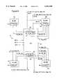
- FIG. 2is a block diagram illustrating the buffer architecture of the network interface device 10 according to an embodiment of the present invention.
- transfer of data frames between the PCI bus interface unit 16, also referred to as the bus interface unit (BIU), and the MAC 20is controlled by a memory management unit (MMU) 52 including the buffer management unit 24 and the SRAM MMU 22 of FIG. 1.
- the MMU 52controls the reading and writing of data to the SRAM 18, illustrated in FIG. 2 as a dual-port receive SRAM portion 18a and a dual-port transmit SRAM portion 18b for convenience.
- the receive SRAM (RX -- SRAM) 18a and the transmit SRAM (TX -- SRAM) 18bmay be implemented as a single memory device, or alternatively as two separate SRAM devices.
- the memory management unitincludes the buffer management unit 24, also referred to as the descriptor management unit, the SRAM MMU 22, and an arbitration unit 54.
- the descriptor management unit 24is configured for fetching, from host computer memory, descriptor information (i.e., transfer information) specifying host computer memory locations for retrieving and storing transmit data and receive data, respectively.
- the arbitration unit 54arbitrates DMA requests for data transmission, data reception, descriptor lists from the descriptor management block 24, and status.
- the SRAM MMU 22includes separate controllers (i.e., management blocks) for each SRAM 18a and 18b, for both read and write operations.
- the network interface device 10operates in two generic clock domains, namely a host computer bus clock domain 56a, and a network clock domain 56b. Since the network interface device 10 needs to send and receive data across two independent clock domains 56, divided by the dotted line 58, the SRAM MMU 22 needs to be able to write and read data to each SRAM 18a and 18b in a manner that tracks memory status independent of the PCI clock in the host computer domain and the MAC clock generated from network activity in the network domain 56b.
- the SRAM MMUincludes a transmit-data bus-side memory management unit block (XB -- MMU) 22a, a transmit-data MAC-side memory management unit block (XM -- MMU) 22b, a receive-data bus-side memory management unit block (RB -- MMU) 22c, a receive-data MAC-side memory management unit block (RM -- MMU) 22d, and a synchronization circuit 60.
- the XB -- MMU 22a and the RM -- MMU 22doperate as write controllers configured for writing frame data into the SRAMs 18b and 18a, respectively.
- the XB -- MMU 22a and the RB -- MMU 22coperate according to the PCI host bus clock (CLK).
- the RM -- MMU 22doperates according to the receive MAC clock (RX -- CLK) received by the MAC 20, and the XM -- MMU 22b operates under the control of the MAC transmit clock (TX -- CLK) received by the MAC 20.
- the XM -- MMU 22b and the RB -- MMU 22coperate as read controllers configured for reading frame data from the SRAMs 18b and 18a, respectively.
- receive data from the MAC 20is written into the RX -- SRAM 18a under the control of the write controller 22d synchronous to the receive clock (RX -- CLK) in the network clock domain 56b.
- Frame data stored in the RX -- SRAM 18ais read and output to the BIU 16 via data path 62a under the control of the receive-data read controller 22c, which reads the frame synchronous to the PCI bus clock signal.
- transmit data to be output onto the network by the MAC 20is written into the TX -- SRAM 18b via data path 62b under the control of the transmit-data write controller 22a, configured for writing the frame data synchronized to the PCI bus clock (CLK).
- the stored transmit datais read and output from the TX -- SRAM 18b to the MAC 20 under the control of the transmit-data read controller 22b according to the MAC transmit clock (TX -- CLK) within the network clock domain 56b.
- the SRAM MMU 22includes a synchronization circuit 60 that asynchronously monitors the status of the RX -- SRAM 18a and the TX -- SRAM 18b, enabling the memory management blocks 22a, 22b, 22c, and 22d to read and write to the memory 18 between the two clock domains 56a and 56b.
- FIG. 3is a diagram illustrating a data structure of a receive data unit in the RX -- SRAM 18a.
- a similar structurealso may be used for storing data in the TX -- SRAM 18b.
- each stored data frame 64includes a frame track field 66 preceding a group of data bytes representing the frame data 68 (i.e., the packet data to be transmitted by the MAC 20), followed by a control field 70.
- the RM -- MMU 22dstores frame track information 66 and the control field 70 related to the receive data frame 68.
- the frame track field 66is used by the RB -- MMU 22c to keep track of the location of the corresponding receive data frame 68 in the RX -- SRAM 18a.
- the frame track 66enables the RB -- MMU 22c to quickly flush a stored data frame 64 having receive data 68 and jump to the beginning of the next stored data frame (e.g., 642), based on an end of frame address field (ENF ADDR), a count (CNT) field specifying the number of DWORDS (D0, D1, . . . , DLAST), and an end of frame (FRM) bit indicating whether the data frame 64 contains valid data ready for reading.
- ENF ADDRend of frame address field
- CNTcount
- CNTcount
- FAMend of frame
- BE -- Lspecifies how many of the bytes in the DLAST field are valid.
- FIG. 5Ais a diagram illustrating multiple data frames (F1, F2, etc.) stored in the RX -- SRAM 18a.
- the RM -- MMU 22dis writing a sequence of data frames 64 (frame 1, frame 2, etc.) into RX -- SRAM 18a using a write pointer (WP)
- WPwrite pointer
- the read controller 22cis reading out the data frames from the RX -- SRAM 18a to the BIU 16 using a read pointer (RP).
- RPread pointer
- the read controllerdiscards (e.g., flushes) a transmit data frame and desires to jump to the beginning of the next data frame
- the synchronization circuit 60must be able to track the start and beginning of each data frame to ensure that the read controller 22c properly locates the beginning of the next data frame.
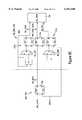
- FIG. 4is a block diagram illustrating in detail the MMU 22.
- the synchronization circuit 60includes asynchronous monitors 82a and 82b for asynchronously monitoring the amount of stored receive data and transmit data in the SRAMs 18a and 18b respectively, enabling the memory management units 22a, 22b, 22c, and 22d to track the number of stored data frames in their respective clock domains.
- the memory management unittracks the number of stored data frames based on the difference between the write frame counter value and the read frame counter values.
- the management block 22aincludes a write counter 84a for incrementing a write pointer value (Tx Write Ptr.) in response writing the transmit data to the random access transmit buffer 18b.
- the management block 22bincludes a read counter 84b for incrementing a read pointer value (Tx Read Ptr.) in response to reading the transmit data from the random access transmit buffer 18b.
- the management block 22dincludes a write counter 84d for incrementing a write pointer value (Rx Write Ptr.) in response to writing the receive data to the random access receive buffer 18a
- the management block 22cincludes a read counter 84c for incrementing a read pointer value (Rx Read Ptr.) in response to reading the receive data from the random access receive buffer 18a.
- the XB -- MMU 22a and the RB -- MMU 22coperate in the PCI bus clock domain (BCLK) 56a, whereas the XM -- MMU 22b and the RM -- MMU 22d operate in the network clock domain 56b. More specifically, the XM -- MMU 22b operates in the network transmit clock domain (XMCLK), and the RM -- MMU operates in the network receive clock domain (RMCLK).
- BCLKPCI bus clock domain
- RMCLKnetwork receive clock domain
- the reading and writing into either of the SRAMs 18a or 18binvolves crossing a clock domain boundary 58, which may adversely affect determining the amount of data in memory.
- transitional valuee.g. 101, 111, or 000
- each management block 22a, 22b, 22c, 22dincludes a counter 84 for the corresponding SRAM, where each counter 84 is configured for counting a pointer value by changing a single bit of a pointer value in response to a corresponding reading or writing operation.
- the write controller (RM -- MMU) 22d for the receive SRAM 18ais configured for writing a frame (e.g., the data frame 64) into the receive SRAM 18a according to a receive MAC clock (RMCLK) 74 synchronized relative to the network clock domain 56b.
- the write controller 22dupon writing an entire data frame 64 into the receive SRAM 18a, outputs a write signal (RM -- ENF) to the synchronization circuit 60 indicating the completed writing of the data frame 64.
- the write controller 22dwrites the data frame 64 in FIG. 3 by receiving the frame data 68 from the MAC 20 according to the RMCLK 74.
- the write controller 22dreserves a portion (location "X" in FIG.
- the write controller 22dthen returns to the frame track field 66 at location "X" and updates the frame track with the appropriate header information, including setting the end of frame address (ENF ADDR), updating the count (CNT) field indicating the number of DWORDS in the frame, the frame bit (FRM) indicating that the memory location 64 stores valid data, and the ENF bit which indicates the last double word of data.
- the write controller 22dconcurrently supplies the frame track information (RM -- FRM -- TRK) to the synchronization circuit 60 for storage in a holding resistor 86a.
- the write controller 22doutputs the write signal to the synchronization circuit 60 after updating the frame track field 66, at which point the SRAM 18a stores a valid data frame 64 at a prescribed location.
- successive writing of framesresults in outputting a corresponding plurality of frame track values (RM -- FRM -- TRK) to the holding register 86a.
- the read controller 22cattempted to read the first frame F1 from the memory location 64 prior to completion by the write controller 22d, as shown in FIG. 5B, the read controller 22c would obtain invalid data, since the frame track field 66 would not yet be updated with valid data.
- the read controller 22csupplies the read frame track information from the accessed memory location (RB -- FRM -- TRK) to indicate the read status for the holding register 86a.
- RB -- FRM -- TRKthe read frame track information from the accessed memory location
- the synchronization circuit 60determines a presence of a complete stored data frame 64 in the random access memory 18a in response to read and write signals and independent of the bus clock 72 and the MAC clock (RMCLK) 74.
- the synchronization circuit 60includes a write receive frame counter (not shown) configured for changing a single bit of a write receive counter value in response to the write signal (RM -- ENF) output from the write controller 22d.
- the synchronization circuit 60also includes a read receive frame counter (not shown) configured for changing a single bit of a read receive frame counter value in response to the read signal (not shown) from the read controller 22c.
- the read controller 22cis configured for reading the frame 64 from the receive SRAM 18a according to a host bus clock (BCLK) 72, where the read controller 22c outputs a read signal to the synchronization circuit 60 in response to the reading of the frame.
- BCLKhost bus clock
- the write receive frame counter and the read receive frame counter in the synchronization circuit 60are implemented as gray code counters, such that only a single bit of a counter value is changed in response to assertion of the status signal from the corresponding memory controller 22.
- Use of the gray code counterensures that any asynchronous comparison between the write receive frame counter and the read receive frame counter does not result in any erroneous values due to multiple bit transitions that may otherwise occur in counters using binary-format representations.
- the gray code counter valuesare compared asynchronously by the synchronization circuit, which outputs a one or more receive frame signal (RX -- FRM -- ONEM) indicating the presence of at least one stored receive frame in the receive SRAM 18a if the receive frame counter values are unequal.
- the above-described arrangementis also used by the XB -- MMU 22a and the XM -- MMU 22b, where the XB -- MMU 22a outputs a signal (not shown) to the synchronization circuit 60 in response to writing a complete data frame into the TX -- SRAM 18b and the XM -- MMU 22b outputs a signal (not shown) to the synchronization circuit 60 in response to reading a complete data frame from the transmit SRAM 18b.
- the synchronization circuitincludes a write transmit frame counter and a read transmit frame counter (not shown), implemented as gray code counters, to asynchronously determine the presence of at least one stored transmit frame in the transmit SRAM 18b.
- the synchronization circuit 60outputs a one or more transmit frame signal (TX -- FRM -- ONEM) in response to asynchronously detecting at least one stored transmit frame in the transmit SRAM 18b.
- the synchronization circuitcan asynchronously determine the presence of at least one stored data frame in either the RX SRAM 18a or the TX SRAM 18b, independent of the clock domains used to write and read into the respective transmit or receive buffers.
- the use of gray code countersmay also be implemented in each of the management blocks 22a, 22b, 22c, and 22d to enable the synchronization circuit 60 to asynchronously determine the amount of transmit data and receive data in the transmit SRAM 18b and receive SRAM 18a, respectively.
- the different clock domains 56a and 56bmay cause contention problems during the writing of frame track information 66 into the holding register 84, depending on whether there are one or more frames in the memory 18a, as shown in FIG. 5A, or less than one full frame, as shown in FIG. 5B.
- the purpose of the holding registers 86a and 86bis to hold frame track information for the current receive frame and transmit frame being read from the RX -- SRAM 18a and TX -- SRAM 18b, respectively.
- the synchronization circuit 60needs to be able to ensure that only valid data is written into the holding registers 86 (i.e., frame track data written into the frame track field 66 after having written a complete data frame).
- the synchronization circuit 60selectively stores frame track information based on the asynchronously determined presence of at least one data frame in the corresponding transmit or receive buffer. For example, the synchronization circuit 60 selectively stores either the first tracking information (RM -- FRM -- TRK) or the second tracking information (RB -- FRM -- TRK) to the holding register 86a based on an asynchronous detection of at least one stored data frame in the receive memory 18a.
- the synchronization circuit 60outputs a one-or-more received frame signal (RX -- FRM -- ONEM) equal to a value of 1 if the RX -- SRAM 18a stores at least one data frame as shown in FIG. 5A. If the memory 18a stores less than a complete frame of data, as shown in FIG.
- priorityis given to the read controller 22c to write the corresponding frame track information into the holding register 86a if one or more frames are stored in memory 18a as shown in FIG. 5A, and grants priority to the write controller 22d if less than one full frame (i.e., a complete frame) is stored in memory 18a, as shown in FIG. 5B.
- the synchronization circuit 60asynchronously monitors the amount of data stored in the random access transmit buffer 18b and the random access receive buffer 18a, enabling each of the management blocks 22a, 22b, 22c, and 22d to operate as event-driven controllers that transfer data in response to detected conditions by the synchronization circuit 60.
- each of the management blocks 22a, 22b, 22c, and 22dcan operate in its corresponding clock domain, without concern of operations in other management blocks operating in other clock domains, by obtaining relevant status conditions from the synchronization circuit 60.
- each management block 22 iincludes a memory counter for incrementing a memory pointer value in response to reading or writing the corresponding data from the corresponding SRAM.
- the XB -- MMU 22aincludes a transmit write counter 84a for incrementing a write pointer value in response to writing a double word (DWORD) into a memory location of the 32-bit SRAM 18b.
- each of the counters 84are implemented as gray code counters, where the counter changes a single bit of the corresponding pointer value in response to the writing or reading of the corresponding data.
- the XB -- MMU 22aincrements the write counter 84a by changing a single bit of the TX Write Ptr.
- the XM -- MMU 22bincludes a read counter 84b that increments the read pointer value (TX Read Ptr.) by changing a single bit of the corresponding read point value in response to reading a DWORD from the random access transmit buffer 18b.
- the RX write counter 84d and the RX read counter 84coperate in the same manner, i.e., by changing a single bit of the corresponding pointer value in response to writing or reading a DWORD from the RX -- SRAM 18a.
- each of the management blocks 22a, 22b, 22c, and 22doutput the corresponding pointer value to the synchronization circuit 60.
- the RX Write Ptr. value and the RX Read Ptr. valueare supplied to an asynchronous monitor 82a that asynchronously determines the amount of stored receive data (e.g., on a double word basis) in the RX -- SRAM 18a.
- the monitor 82amay include a comparator for performing a gray code comparison of the read and write pointer values.
- the asynchronous comparator 82aasynchronously monitors the amount of data stored in the random access receive buffer 18a.
- the asynchronous monitor 82basynchronously monitors the amount of data stored in the random access transmit buffer 18b by performing a gray code comparison between the TX Write Ptr. value and the TX Read Ptr. value from the counters 84a and 84b, respectively.
- the synchronization circuit 60in response to the asynchronous monitoring of the amount of data stored in the RX -- SRAM 18a and the TX -- SRAM 18b outputs various status indicators, flags, and status value, either asynchronously or synchronized to one of the three clock domains to enable a controller element to receive valid data. For example, the synchronization circuit 60 outputs a value indicating the amount of free bytes (TX -- FREE -- BYTES) to the descriptor management 24 synchronous with the host bus clock (BCLK).
- TX -- FREE -- BYTESthe descriptor management 24 synchronous with the host bus clock (BCLK).
- the sync block 60also outputs the TX -- FREE -- BYTES information to the XM -- MMU 22b synchronous with the transmit MAC clock (XMCLK), enabling the XM -- MMU 22b to read the amount of free bytes in the TX -- SRAM in the appropriate clock domain.
- the sync block 60outputs an empty flag (TX -- SRAM -- EMPTY) to the descriptor management 24 synchronous with the BCLK, and to the XM -- MMU 22b synchronous with the XMCLK.
- the synchronization block 60outputs a transmit request signal (XMREQ), shown in FIG. 2, to the MAC 20 indicating that a sufficient amount of transmit data is stored in TX -- SRAM 18b to initiate network transmission.
- XMREQtransmit request signal
- the MAC 20can then output an advance signal (XMADV) in response to the XMREQ signal and in response to a detected idle condition on the media to start transmit data transmission.
- XMADVadvance signal
- the XM -- MMU 22bcan selectively output transmit data from the TX -- SRAM 18b based on flags and the amount of data stored in the TX -- SRAM 18b, as asynchronously determined by the sync block 60.
- the RM -- MMUselectively holds writing received data to the RX -- SRAM 18a in response to a full flag (RX -- SRAM -- FULL) from the sync block 60, indicating that the amount of stored receive data in the RX -- SRAM 18a has exceeded a prescribed amount.
- the synchronization block 60also outputs information to the descriptor management 24, including data indicating the amount of data available in the RX -- SRAM 18a (RX -- BYTE -- AVAIL) and an empty flag (RX -- SRAM -- EMPTY).
- the descriptor management block 24is configured for initiating requests to the arbitration unit 54 for transferring transmit and receive data from and to host system memory based on the information in flags output by the sync block 60.
- the XB -- MMU 22a and the RB -- MMU 22coperate based on burst transfers on the PCI bus that are initiated by the descriptor management 24.
- the XB -- MMU 22a and the RB -- MIU 22cmay also operate under the control of a host CPU if the network interface device 10 is configured to operate in slave mode.
- the management blocks 22a, 22b, 22c, and 22ddo not need to synchronize to another clock domain to compare information.
- the sync block 60enables the other management blocks to operate exclusively in their respective domains, without the necessity of synchronizing to another clock domain.
- the disclosed architectureenables faster, more reliable design implementation without the necessity of synchronizing two different clock domains unnecessarily.
- FIG. 6is a diagram illustrating descriptor lists in system memory, used by the descriptor management block 24 to obtain information related to retrieval and storage of transmit data and receive data into system memory, respectively.
- the descriptors 100identify locations 102 in system memory 104 that store at least portions 106 of a data frame, respectively.
- each descriptor 100specifies the starting address (e.g., TX -- BUF -- ADDR) of where the descriptor management 24 may find the transmit data portion 106 in system memory.
- the descriptor 100also includes control information, the buffer length, etc., enabling the network interface device 10 to perform a DMA transfer by the PCI bus. After the descriptor management 24 fetches the descriptor information 100, the descriptor management 24 will write status information back to system memory upon completion of the data transfer (e.g., reading transmit data from system memory, or writing receive data to system memory).
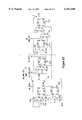
- FIG. 7is a flow diagram illustrating operations by the descriptor management 24 in controlling the transfer of frame data between the system memory 104 and the buffer memory 18.
- the descriptor managementreceives from the host computer descriptor index information that specifies the location in system memory of the descriptors 100.
- the host CPUmay first write the frame data 106 into the system memory 104, then write the corresponding descriptors 100 in a second location in system memory.
- the host computerwill then write to a control register in the descriptor management 24 addressable by the host CPU on the PCI bus, that identifies the location of the descriptors 100 and releases control of the descriptors from the host CPU to the network interface device 10.
- the descriptor management 24retrieves the descriptor information 100 from the host computer memory in step 202 by performing a DMA read operation via the PCI bus 12. Specifically, the descriptor management 24 generates a descriptor read request from the arbiter 54.
- the arbiter 54controls access of the PCI bus 12 by the network interface device 10 in DMA mode. As such, the arbiter 54 prioritizes between frame data transfer requests and descriptor requests to avoid overflow or underflow conditions in the RX -- SRAM 18a or the TX -- SRAM 18b.
- the arbiter 54returns a grant to the descriptor management 24 and in response generates a PCI bus request signal (REQ#) on the PCI bus.
- the PCI bus arbitere.g., the host CPU
- the descriptor management 24in response fetches the descriptor information 100 in step 202.
- each descriptor 100includes a 64-bit system address (e.g., TX -- BUF -- ADDR) that points to a corresponding system memory location 102 i .
- the descriptor managementalso determines the length of the corresponding frame data fragment 106 by reading the corresponding length from the buffer length field (BUF LENGTH).
- the descriptor management 24initiates a second PCI bus transfer in step 206 to transfer the frame data 106 i between the system memory 104 and the appropriate SRAM buffer 18.
- the descriptor management 24issues a third PCI bus transfer in step 208 to write status information to the host computer memory based on the successful burst transfer in step 206, releasing control of the descriptors 100 back to the driver software executed by the host CPU.
- FIG. 6is disclosed with respect to the transmit buffer in system memory
- the above-described procedures in FIGS. 6 and 7is identical for receive data
- the descriptor management 24fetches descriptor information from system memory that specifies the locations in system memory where the network interface device 10 is to transfer the receive data from the receive SRAM 18a to the system memory 104.
- the descriptor managementfollows the same sequence of fetching descriptor information, burst transferring the stored receive data to the destination via the host bus based on the amount of stored receive data in the RX -- SRAM and the corresponding descriptors, and writing status information to the host computer memory based on the burst transfer of the stored receive data to the destination.
- the descriptor management 24writes a single double word (DWORD) of status information for transmit data, and two DWORDs of status information for receive data.
- DWORDsingle double word
- the descriptor management 24maintains a certain number of descriptors in the network interface device 10 as needed to transfer transmit data and receive main data between the system memory and the random access buffer memories 18. Hence, the amount of memory space on the network interface device needed to control data transfers is minimized. Further, the disclosed arrangement provides an efficient protocol with the driver software executed by the host CPU, minimizing contention conditions for determining whether certain descriptors 100 are to be accessed by the network interface device 10 or the driver software.
- FIGS. 8A, 8B, 8C, and 8Dare diagrams illustrating the data flow architecture of the XB -- MMU 22a, the XM -- MMU 22b, the RM -- MMU 22d, and the RB -- MMU 22c, respectively.
- Each of the management blocks 22a, 22b, 22c, and 22dinclude delay flip flops 210 and holding registers 212.
- Each holding register 212includes a multiplexer and a D flip flop, enabling the holding register 212 to selectively store input data for a multiple number of clock cycles used to drive the corresponding D flip flop, based on controlling the selection input to the multiplexer.
- the bus interface unit 16includes a D flip flop 210a that latches the data (XB -- DATA) from the AD signal path of the PCI bus 12 in response to the host bus clock (BCLK).
- the D flip flop 210aoutputs the 32-bit XB -- DATA signal to the holding register 212b, which selectively latches the XB -- DATA in response to an XB -- ADV signal received from the BIU 16.
- the multiplexer of holding register 212bis a multiple-selection input multiplexer, such that byte packing may be performed on the received XB -- DATA.
- the data output by the holding register 212b(XB -- SRAM -- DATA) is aligned in the TX -- SRAM to avoid the presence of invalid data within the TX -- SRAM due to invalid byte lanes (i.e., "holes").
- the holding register 212aoutputs the write address pointer (XB -- ADDR), as controlled by the incrementer 214a, controlled by the XB -- MMU 22a.
- the supply of data from the PCI bus 12is performed in the host bus (BCLK) domain.
- the XB -- ADV signal from the BIU 16enables the XB -- MMU to increment the write pointer in holding register 212a, and to supply data to the dual-port TX -- SRAM 18b.
- FIG. 8Bis a diagram illustrating in further detail the data path of the XB -- MMU 22b and the MAC 20.
- the XB -- MMU 22bincludes holding registers 212d, 212e, delay flip flop 210b, and incrementer 214b.
- the MAC 20includes holding register 212f, and holding register 212g.
- the incrementer 214bunder the control of the XM -- MMU 22b, controls the read address pointer stored in holding register 212d.
- the MAC 20outputs an advance signal (XM -- ADV), used to increment the read pointer in holding register 212d and the read signal in holding register 212e.
- the MAC 20is able to assert the XM -- ADV advance signal until the TX -- SRAM is empty, based on an empty flag TX -- SRAM -- EMPTY) generated by the synchronization block 60. Note the last two holding registers 212f and 212g are part of the MAC 20.
- FIG. 8Cis a diagram illustrating the data path in the RM -- MMU 22d.
- the MAC 20has a delay flip flop 210 that outputs the data in nibble (i.e., 4 bits) mode, such that the advance signal (RM -- ADV) is asserted by the MAC 20 once every eight clock cycles (RMCLK), such that there is one clock cycle for each nibble.
- RMCLKclock cycles
- the RM -- MMU 22d and the XB -- MMU 22awill multiplex frame track information into the RX -- SRAM -- DATA and XB -- SRAM -- DATA paths, respectively.
- the RM -- MMU 22dalso includes holding registers 210c, 212h, and 212i, which function similar to those components in 22a.
- FIG. 8Dis a diagram illustrating in detail the data path for the RB -- MMU 22c.
- the RB -- MMU 22coutputs the data onto the AD signal path of the PCI bus 12 with zero wait states in a DMA transfer, based on the holding registers 212l, 212m, 212n, and the multiplexer 216.
- the advance signal RB -- ADV output by the BIU 16is used to drive the read pointer stored in holding register 212j, and the read pointer stored in holding register 212k.
- the read pointer value stored in holding register 212jis controlled by the incrementer 214c.
- the RX -- SRAM 18aoutputs a double word of data from a prescribed location pointed to by the read pointer value (RB -- ADDR) as a 32-bit signal RB -- SRAM -- DATA.
- the holding register 212loutputs the signal RB -- DATA based on the RB -- ADV signal and the bus clock (BCLK) signal.
- the holding register 212lalso performs byte alignment relative to the PCI bus 12 based on byte alignment (BE -- L) signals received by the multiplexer 220 from the descriptor management 24.
- the holding register 212loutputs the RB -- DATA signals to the holding register 212m and the multiplexer 216.
- the holding register 212mis configured to resolve any wait states or bus termination conditions (e.g., disconnect, retry) that may occur on the PCI bus 12.
- the multiplexer 216 and the multiplexer of the holding register 212nare controlled by a state machine (not shown) in the bus interface unit.
- DMA transfer sequencesare initiated by the descriptor management 24 generating a request to the arbiter 54.
- the BIU 16issues a grant signal to the MMU 52 concurrent with issuing a request (REQ#) signal on the PCI bus.
- the BIU 16also asserts the advance signal (RB -- ADV) for a prescribed number of clock cycles, causing the holding registers 212l, 212m, and 212n to be loaded with receive data from the SRAM 18a even before transmission on the PCI bus 12 begins by the network interface device 10.
- the receive datais effectively preloaded into the holding registers 212l, 212m, and 212n in anticipation of a DMA burst, eliminating the occurrence of any wait states following the address phase of the PCI burst.
- the BIU 16can selectively control the RB -- ADV signal in response to detected conditions on the PCI bus.
- the RB -- MMU 22c and the BIU 16can suspend the transfer of data on the PCI bus, and continue outputting receive data on the PCI bus 12 without the necessity of reloading the holding registers 212l, 212m, and 212n.
- the memory management unitprovides an efficient manner for reading and writing frame data from a transmit random access buffer memory and a receive random access buffer memory, despite the presence of multiple clock domains.
- the use of holding registersalso enables the efficient pipelining of data, such that zero wait states are encountered during a DMA burst write, and minimal delay is encountered during retransmission in response to a detected disconnect or retry condition on the PCI bus.
Landscapes
- Engineering & Computer Science (AREA)
- Computer Networks & Wireless Communication (AREA)
- Signal Processing (AREA)
- Small-Scale Networks (AREA)
Abstract
Description
1. Technical Field
The present invention relates to network interfacing and more particularly, to methods and systems for buffering data between a host bus interface and a media access controller accessing Ethernet (IEEE 802.3) media.
2. Background Art
Network interface devices handle packets of data for transmission between a host computer and a network communications system, such as a local area network. The host computer may be implemented as a client station, a server, or a switched hub. One primary function of the network interface device is to buffer data to compensate for timing discrepancies between the clock domain of the host computer and the clock domain of the network.
Network interface devices typically include a first in, first out (FIFO) buffer memory for storing transmit and receive data, where the transmit data is stored in a transmit FIFO prior to transmission on the network media by the MAC, and receive data is stored in a receive FIFO by the MAC prior to transfer to the host computer via the host computer bus interface.
One disadvantage with the use of a FIFO for a transmit buffer or a receive buffer is the increased latency encountered during the buffering process. The latency of the network interface device is the time delay between the time that a data frame is supplied to the network interface device and the time the data is transmitted on the network media, or vice versa.
An additional disadvantage with the use of a FIFO for transmit buffer or receive buffer is the increasing complexity associated with maintaining status information for each data frame stored in the FIFO buffer. If a stored data frame is to have corresponding status information, then an additional FIFO buffer would be required for storing the status information for each stored data frame. Hence, a transmit buffer may require a data frame FIFO for the actual frame data, and a status FIFO for storing the corresponding status information for each data frame. Such an arrangement would result in a substantial increase in the amount of area required on a chip for the status FIFO. In addition, additional synchronization logic would be required to maintain correspondence between the stored frame data and the corresponding status data, increasing the cost and complexity of the network interface device.
An additional problem caused by the buffering of data between the clock domain of the host computer and the clock domain of the network interface device is buffer overflow or underflow. For example, buffer overflow can occur when the time domains between the host bus and the network media are uncontrollable to the extent that data is stored in the buffer at a rate faster than the data can be removed, resulting in an overflow situation. Conversely, underflow occurs if data is removed from the FIFO buffer faster than the data can be supplied.
Hence, the non-synchronous relationship between the host bus clock domain and the network clock domain have required the necessity of FIFO buffers to compensate for timing discrepancies between the host computer and the network.
Another fundamental problem with use of a FIFO as a transmit buffer or receive buffer is that there is no convenient way for the network interface device to bypass, or "flush," invalid data. For example, if the media access controller receives a runt packet from the network (i.e., an invalid packet less than the minimum required frame size of 64 bytes), the MAC cannot cause the invalid data stored in the FIFO to be flushed, without eliminating the entire contents of the receive FIFO. Hence, the invalid data is transferred via the host computer bus and stored in host computer memory, before the host computer can determine that the transferred data is invalid. The reduction in throughput may have substantial effects, especially in full-duplex networks, where the host computer bus is heavily utilized by the network interface device for simultaneous transmission and reception of data frames on the network medium.
An additional problem encountered with conventional network interface devices is the latency encountered during host bus transfers. In particular, two types of bus transfers may be used, namely master mode and slave mode. In master mode, the network interface device operates as a master, and initiates the transfer of data across the host bus by requesting use of the bus, and then transferring the data as a data burst. One example of a host bus is the peripheral component interconnect (PCI) local bus, where a transfer of data over a PCI bus includes an address phase followed by one or more contiguous data phases. The PCI bus protocol makes use of a centralized, synchronous arbitration scheme in which each PCI master must arbitrate for each transaction by use of a request signal and a grant signal. For example, a network interface device having data to transfer (e.g., either receive data or transmit data) will assert a request signal to request use of the bus. Typically, a host CPU will respond with a grant signal which is followed by assertion of a frame signal that together identify when the bus is available for use by the network interface.
One problem in conventional network interface devices is the occurrence of wait states following an address phase on the PCI bus. Such wait states cause increased latency on the PCI bus, further reducing the overall throughput of the network interface device.
An additional problem with conventional network interface devices is the occurrence of wait states encountered during a complex bus termination condition, where certain events on the PCI bus forcibly halt a PCI bus data transfer. Two examples of complex conditions include when a host memory is not ready to receive a data transfer after the bus has been secured, or when the host memory becomes unable to continue receiving data following initiation of the data transfer. In either case, the target asserts a STOP# signal on the PCI bus to terminate the data transfer. Prior art systems frequently lose data from the FIFO buffer memory in response to encountering such complex conditions, for example retry or disconnect states. Hence, complicated recovery arrangements are conventionally required in prior art systems to mitigate the loss of data. For example, higher network protocol layers may need to send a message across the network, requesting the transmitting station to resend a data packet.
There is a need for an arrangement that enables use of a random access memory in a network controller, as opposed to a FIFO buffer, to compensate for timing discrepancies between the host computer and the network.
There is also a need for an arrangement enabling the use of a random access memory as a buffer in a network interface device, where potential synchronization problems between the clock domain of the host computer and the clock domain of the network are resolved to enable efficient control of the random access memory during the writing and reading of transmit or receive data.
There is also a need for an arrangement in a network interface device, where a synchronization circuit controls priority between writing and reading operations to and from the random access memory to enable efficient memory management for monitoring the status of stored frame data.
There is also a need for an arrangement in a network interface device, where a network interface architecture asynchronously monitors the status of data stored in a random access transmit buffer and a random access receive buffer to enable multiple memory controllers to store and read data into the random access memories using multiple clock domains.
There is also a need for an arrangement in a network interface device having a memory controller that enables access to a random access transmit buffer or a random access receive buffer according to either a direct memory access (DMA) or slave access.
There is also a need for an arrangement in a network interface device having a circuit that asynchronously monitors the status of a random access transmit buffer and a random access receive buffer, enabling memory controllers to operate in response to prescribed conditions detected by the synchronization circuit.
These and other needs are attained by the present invention, where a memory management unit, configured for controlling transfer of transmit data and receive data into respective random access transmit and receive buffers, includes a synchronization circuit for asynchronously monitoring the amount of data stored in the random access transmit buffer and the random access receive buffer. The asynchronous monitoring by the synchronization circuit enables memory management unit operations to be performed in respective independent clock domains.
According to one aspect of the present invention, a method in a network interface device for sending data frames from a host computer to a network medium comprises storing transmit data received from a host bus into a random access transmit buffer according to a host bus clock, asynchronously monitoring the amount of data stored in the random access transmit buffer, and outputting the stored transmit data from the random access transmit buffer to a media access controller according to a transmit clock independent from the host bus clock and based on the asynchronously monitoring step, for transmission on the network medium. The asynchronous monitoring of the amount of data stored in the random access transmit buffer enables the transmit data to be stored in the random access transmit buffer according to the host bus clock domain, and also enables the transmit data to be output from the random access transmit buffer according to a network transmit clock, independent from the host bus clock, with minimal latency in the network interface device. Since the amount of data stored in the random access transmit buffer is monitored asynchronously, operations in the network interface device may be performed on an event-driven basis, where the asynchronous detection of events within the random access transmit buffer enables optimized performance in the appropriate clock domain.
Another aspect of the invention provides a method in a network interface device for receiving data frames from a network medium to a host computer, comprising storing receive data received from a media access controller into a random access receive buffer according to a network receive clock, asynchronously monitoring the amount of data stored in the random access receive buffer, and outputting the stored receive data from the random access receive buffer to a host bus interface according to a host bus clock independent from the network receive clock and based on the asynchronously monitoring step, for transmission on a host bus.
Still another aspect of the present invention provides a network interface device comprising a media access controller configured for simultaneously outputting transmit data according to a network transmit clock, and receiving receive data from a network medium according to a network receive clock, a bus interface unit configured for transferring via a host bus the receive data and the transmit data to and from a host computer memory according to a host bus clock, a random access receive buffer configured for storing the receive data received by the media access controller according to the network receive clock, and outputting the stored receive data to the bus interface unit according to the host bus clock, a random access transmit buffer configured for storing the transmit data supplied by the bus interface unit according to the host bus clock, and outputting the stored transmit data to the media access controller according to the network transmit clock, and a memory management unit. The memory management unit is configured for controlling the transfer of the transmit data and receive data in the random access transmit buffer and the random access receive buffer, and includes a synchronization circuit for asynchronously monitoring the amount of data stored in the random access transmit buffer and the random access receive buffer. The asynchronous monitoring by the synchronization circuit enables the memory management unit to interact with the media access controller, the bus interface unit, and the random access transmit and receive buffers on an event-driven basis, where operations can be performed in the appropriate clock domain based on the asynchronous monitoring of events in the synchronization circuit.
This aspect of the network interface device is particularly advantageous in the case where the memory management unit includes first, second, third, and fourth management blocks configured for controlling the transfer of transmit data to and from the random access transmit buffer, and receive data to and from the random access receive buffer, respectively. Hence, each of the management blocks can be optimized for performing its corresponding memory functions in its corresponding clock domain by obtaining any relevant status information from the synchronization circuit. Hence, the network interface device can be configured for efficient transfer of transmit and receive data, in a manner that eliminates any contention issues between the host bus clock, the network transmit clock or the network receive clock.
Additional objects, advantages and novel features of the invention will be set forth in part in the description which follows, and in part will become apparent to those skilled in the art upon examination of the following or may be learned by practice of the invention. The objects and advantages of the invention may be realized and attained by means of the instrumentalities and combinations particularly pointed out in th e appended claims.
Reference is made to the attached drawings, wherein elements having the same reference numeral designations represent like elements throughout and wherein:
FIGS. 1A and 1B show block diagrams illustrating how the systems in FIGS. 1A and 1B are coupled together;
FIGS. 1A and 1B illustrate an exemplary network interface device including a synchronization circuit for controlling buffer memory controllers according to an embodiment of the present invention;
FIG. 2 is a block diagram illustrating the buffer architecture of the network interface device of FIG. 1 according to an embodiment of the present invention.
FIG. 3 is a diagram illustrating an exemplary data structure of a data frame stored in the random access memory of FIGS. 1 and 2.
FIG. 4 is a block diagram illustrating in detail the architecture of the memory management unit of FIG. 2 according to an embodiment of the present invention.
FIGS. 5A and 5B are diagrams illustrating storage conditions when the receive memory of FIG. 2 stores at least one full frame of data and less than one full frame of data, respectively.
FIG. 6 is a diagram illustrating descriptor lists stored in system memory for use by the descriptor management controller of FIG. 2.
FIG. 7 is a diagram illustrating a method of transferring frame data by thedescriptor management 18 between system memory and the random access buffer memories.
FIGS. 8A, 8B, 8C, and 8D are block diagrams illustrating holding registers used to buffer data input to the transmit random access memory, output from the transmit random access memory, input to the receive random access buffer memory, and output from the receive random access buffer memory, respectively.
The present invention will be described with the example of a network interface device in a packet switched network, such as an Ethernet (IEEE 802.3) network. A description will first be given of a network interface architecture, followed by the arrangement for monitoring the storage of a data frame in a buffer memory, independent of host computer clock and network data clock domains. It will become apparent, however, that the present invention is also applicable to other network interface device systems.
FIG. 1 is a block diagram of an exemplarynetwork interface device 10 that accesses the media of an Ethernet (ANSI/IEEE 802.3) network according to an embodiment of the present invention.
Thenetwork interface device 10, preferably a single-chip, 32-bit Ethernet controller, provides an interface between alocal bus 12 of a computer, for example a peripheral component interconnect (PCI) local bus, and an Ethernet-basedmedia 50.
Theinterface 10 includes a PCIbus interface unit 16, abuffer memory portion 18, and a media access controller interface device (MAC) 20. The PCIbus interface unit 16 includes aPCI slave interface 16a and aDMA interface 16b. Theslave interface 16a manages PCI control and status information including reading and programming of the PCI status registers, but may also be configured for managing slave transfers via the PCI bus with a host CPU. TheDMA interface 16b manages DMA transfers by thenetwork interface device 10 to and from system memory. Hence, the PCIbus interface unit 16 can be selectively configured for PCI transfers in slave and/or master (e.g., DMA) mode.
Thememory portion 18 includes a 32-bit SRAM implemented directly on thenetwork interface device 10. According to the disclosed embodiment, theSRAM 18 may be accessed in a random access manner under the control of amemory management unit 22, or may be segmented into a receiveportion 18a and a transmitportion 18b for receive and transmit paths, respectively.
Thenetwork interface device 10 also includes abuffer management unit 24 configured for managing DMA transfers via theDMA interface 16b. Thebuffer management unit 24 manages DMA transfers based on DMA descriptors in host memory that specify start address, length, etc. Thebuffer management unit 24 initiates a DMA read from system memory into the transmitbuffer 18b by issuing an instruction to theDMA interface 16b, which translates the instructions into PCI bus cycles. Hence, thebuffer management unit 24 contains descriptor management for DMA transfers, as well as pointers associated with storing and reading data from thememory portion 18. Although thebuffer management unit 24 and thememory management unit 22 are shown as discrete components, the two units may be integrated to form a memory management unit controlling all transfers of data to and from thememory unit 18.
TheMAC 20 includes aMAC core 26, a general purpose serial interface (GPSI) 28, a media independent interface (MII) 30 for connecting to external 10 Mb/s or 100 Mb/s physical (PHY) transceivers, an external address detection interface (EADI) 32, an attachment unit interface (AUI) 34 having a Manchester encoder and decoder, and a 10/100 Mb/s twisted pair transceiver media attachment unit (MAU) 36.
Thenetwork interface device 10 also includes anetwork port manager 38 configured for performing MII handshaking between two devices on an MII bus via theMII port 30. Such MII handshaking may include link information, programming information at the MII layer using a management data clock (MDC), and management data input/output (MDIO) paths.
The auto-negotiation portion 40 performs IEEE-compliant negotiation with a link partner on the PHY layer to exchange data indicating whether the link partner is capable of operating at 10 Mb/s, 100 Mb/s, and whether the link should be half-duplex or full-duplex.
TheLED controller 44 selectively controls the generation of LED output signals based upon the internal decoding logic and network interface device status registers (not shown). Thenetwork interface device 10 also includes an IEEE 1149.1-compliant JTAG boundary scan testaccess port interface 36.
TheEEPROM interface 42 connects to an EEPROM on either a network interface device adapter card or the motherboard of the host computer via a serial interface link. The EEPROM (not shown in FIG. 1) will be programmed with configuration information related to the network interface device, enabling the network interface device to be configured during initialization via theEEPROM interface 42. Once initialized, the network interface device stores the configuration information in internal registers (not shown), enabling the network interface device to operate independently of the host computer in the event the host computer is powered down. Hence, the network interface device can be configured to operate while the host computer is in a stand-by mode, enabling the network interface device to output power up information to logic within the host computer to enable the host computer to automatically turn on in response to data packets received from the network and having a specific protocol, described below.
FIG. 2 is a block diagram illustrating the buffer architecture of thenetwork interface device 10 according to an embodiment of the present invention. As shown in FIG. 2, transfer of data frames between the PCIbus interface unit 16, also referred to as the bus interface unit (BIU), and theMAC 20 is controlled by a memory management unit (MMU) 52 including thebuffer management unit 24 and theSRAM MMU 22 of FIG. 1. TheMMU 52 controls the reading and writing of data to theSRAM 18, illustrated in FIG. 2 as a dual-port receiveSRAM portion 18a and a dual-port transmitSRAM portion 18b for convenience. It will be recognized in the art that the receive SRAM (RX-- SRAM) 18a and the transmit SRAM (TX-- SRAM) 18b may be implemented as a single memory device, or alternatively as two separate SRAM devices.
As shown in FIG. 2, the memory management unit includes thebuffer management unit 24, also referred to as the descriptor management unit, theSRAM MMU 22, and anarbitration unit 54. Thedescriptor management unit 24 is configured for fetching, from host computer memory, descriptor information (i.e., transfer information) specifying host computer memory locations for retrieving and storing transmit data and receive data, respectively. Thearbitration unit 54 arbitrates DMA requests for data transmission, data reception, descriptor lists from thedescriptor management block 24, and status.
TheSRAM MMU 22 includes separate controllers (i.e., management blocks) for eachSRAM network interface device 10 operates in two generic clock domains, namely a host computerbus clock domain 56a, and anetwork clock domain 56b. Since thenetwork interface device 10 needs to send and receive data across two independent clock domains 56, divided by the dottedline 58, theSRAM MMU 22 needs to be able to write and read data to eachSRAM network domain 56b.
According to the disclosed embodiment, the SRAM MMU includes a transmit-data bus-side memory management unit block (XB-- MMU) 22a, a transmit-data MAC-side memory management unit block (XM-- MMU) 22b, a receive-data bus-side memory management unit block (RB-- MMU) 22c, a receive-data MAC-side memory management unit block (RM-- MMU) 22d, and asynchronization circuit 60. The XB-- MMU 22a and the RM-- MMU 22d operate as write controllers configured for writing frame data into theSRAMs MAC 20, and the XM-- MMU 22b operates under the control of the MAC transmit clock (TX-- CLK) received by theMAC 20. The XM-- MMU 22b and the RB-- MMU 22c operate as read controllers configured for reading frame data from theSRAMs MAC 20 is written into the RX-- SRAM 18a under the control of thewrite controller 22d synchronous to the receive clock (RX-- CLK) in thenetwork clock domain 56b. Frame data stored in the RX-- SRAM 18a is read and output to theBIU 16 viadata path 62a under the control of the receive-data readcontroller 22c, which reads the frame synchronous to the PCI bus clock signal.
Similarly, transmit data to be output onto the network by theMAC 20 is written into the TX-- SRAM 18b viadata path 62b under the control of the transmit-data write controller 22a, configured for writing the frame data synchronized to the PCI bus clock (CLK). The stored transmit data is read and output from the TX-- SRAM 18b to theMAC 20 under the control of the transmit-data readcontroller 22b according to the MAC transmit clock (TX-- CLK) within thenetwork clock domain 56b.
The presence of twoseparate clock domains random access memory 18 requires that the write controller and read controller devices be coordinated and synchronized to ensure that no contention issues arise due to the relative independence of the twoclock domains SRAM MMU 22 includes asynchronization circuit 60 that asynchronously monitors the status of the RX-- SRAM 18a and the TX-- SRAM 18b, enabling thememory management blocks memory 18 between the twoclock domains memory management units synchronization circuit 60 according to a prescribed arbitration logic.
FIG. 3 is a diagram illustrating a data structure of a receive data unit in the RX-- SRAM 18a. A similar structure also may be used for storing data in the TX-- SRAM 18b. As shown in FIG. 3, each storeddata frame 64 includes aframe track field 66 preceding a group of data bytes representing the frame data 68 (i.e., the packet data to be transmitted by the MAC 20), followed by acontrol field 70. In this case, the RM-- MMU 22d storesframe track information 66 and thecontrol field 70 related to the receivedata frame 68. Theframe track field 66 is used by the RB-- MMU 22c to keep track of the location of the corresponding receivedata frame 68 in the RX-- SRAM 18a. Hence, theframe track 66 enables the RB-- MMU 22c to quickly flush a storeddata frame 64 having receivedata 68 and jump to the beginning of the next stored data frame (e.g., 642), based on an end of frame address field (ENF ADDR), a count (CNT) field specifying the number of DWORDS (D0, D1, . . . , DLAST), and an end of frame (FRM) bit indicating whether thedata frame 64 contains valid data ready for reading. The byte enable-last field (BE-- L) specifies how many of the bytes in the DLAST field are valid.
FIG. 5A is a diagram illustrating multiple data frames (F1, F2, etc.) stored in the RX-- SRAM 18a. Assume that the RM-- MMU 22d is writing a sequence of data frames 64 (frame 1,frame 2, etc.) into RX-- SRAM 18a using a write pointer (WP), while theread controller 22c is reading out the data frames from the RX-- SRAM 18a to theBIU 16 using a read pointer (RP). If the read controller discards (e.g., flushes) a transmit data frame and desires to jump to the beginning of the next data frame, thesynchronization circuit 60 must be able to track the start and beginning of each data frame to ensure that theread controller 22c properly locates the beginning of the next data frame.
FIG. 4 is a block diagram illustrating in detail theMMU 22. Thesynchronization circuit 60 includesasynchronous monitors SRAMs memory management units management block 22a includes a write counter 84a for incrementing a write pointer value (Tx Write Ptr.) in response writing the transmit data to the random access transmitbuffer 18b. Themanagement block 22b includes aread counter 84b for incrementing a read pointer value (Tx Read Ptr.) in response to reading the transmit data from the random access transmitbuffer 18b. Similarly, themanagement block 22d includes awrite counter 84d for incrementing a write pointer value (Rx Write Ptr.) in response to writing the receive data to the random access receivebuffer 18a, and themanagement block 22c includes a readcounter 84c for incrementing a read pointer value (Rx Read Ptr.) in response to reading the receive data from the random access receivebuffer 18a. As described above, the XB-- MMU 22a and the RB-- MMU 22c operate in the PCI bus clock domain (BCLK) 56a, whereas the XM-- MMU 22b and the RM-- MMU 22d operate in thenetwork clock domain 56b. More specifically, the XM-- MMU 22b operates in the network transmit clock domain (XMCLK), and the RM-- MMU operates in the network receive clock domain (RMCLK).
Hence, the reading and writing into either of theSRAMs clock domain boundary 58, which may adversely affect determining the amount of data in memory.
For example, assume a read frame counter pointer value (Rx Read Ptr.) and a write counter pointer value (Rx Write Ptr.) are stored in binary counters, where a write counter has a value (WR=100) and a read counter in the second independent clock domain transitions from (RD=011) to (RD=100). Since theclock domains
One possible solution for preventing asynchronous comparisons during counter transitions is to provide latched outputs for the counter values. However, such an arrangement would severely degrade the timing performance of the random access memory as a buffer device.
According to the disclosed embodiment, eachmanagement block
As shown in FIG. 4, the write controller (RM-- MMU) 22d for the receiveSRAM 18a is configured for writing a frame (e.g., the data frame 64) into the receiveSRAM 18a according to a receive MAC clock (RMCLK) 74 synchronized relative to thenetwork clock domain 56b. Thewrite controller 22d, upon writing anentire data frame 64 into the receiveSRAM 18a, outputs a write signal (RM-- ENF) to thesynchronization circuit 60 indicating the completed writing of thedata frame 64. Specifically, thewrite controller 22d writes thedata frame 64 in FIG. 3 by receiving theframe data 68 from theMAC 20 according to the RMCLK 74. Thewrite controller 22d then reserves a portion (location "X" in FIG. 5B) of the prescribedmemory location 64 of the transmitSRAM 18a by first writing null data for theframe track 66 to hold header information. Theactual frame data 68 is then written (location "Y"), followed by control information 70 (at location "Z"). Following the writing of thecontrol information 70 at location "Z", thewrite controller 22d then returns to theframe track field 66 at location "X" and updates the frame track with the appropriate header information, including setting the end of frame address (ENF ADDR), updating the count (CNT) field indicating the number of DWORDS in the frame, the frame bit (FRM) indicating that thememory location 64 stores valid data, and the ENF bit which indicates the last double word of data. Thewrite controller 22d concurrently supplies the frame track information (RM-- FRM-- TRK) to thesynchronization circuit 60 for storage in a holdingresistor 86a.
Hence, thewrite controller 22d outputs the write signal to thesynchronization circuit 60 after updating theframe track field 66, at which point theSRAM 18a stores avalid data frame 64 at a prescribed location. As shown in FIG. 5A, successive writing of frames results in outputting a corresponding plurality of frame track values (RM-- FRM-- TRK) to the holdingregister 86a. Assuming, however, that theread controller 22c attempted to read the first frame F1 from thememory location 64 prior to completion by thewrite controller 22d, as shown in FIG. 5B, theread controller 22c would obtain invalid data, since theframe track field 66 would not yet be updated with valid data. In addition, theread controller 22c supplies the read frame track information from the accessed memory location (RB-- FRM-- TRK) to indicate the read status for the holdingregister 86a. Hence, invalid frame track data would be written to the holdingregister 86a if the read controller attempted a read operation before completion of the corresponding write operation.
According to the disclosed embodiment, thesynchronization circuit 60 determines a presence of a complete storeddata frame 64 in therandom access memory 18a in response to read and write signals and independent of the bus clock 72 and the MAC clock (RMCLK) 74. Specifically, thesynchronization circuit 60 includes a write receive frame counter (not shown) configured for changing a single bit of a write receive counter value in response to the write signal (RM-- ENF) output from thewrite controller 22d. Thesynchronization circuit 60 also includes a read receive frame counter (not shown) configured for changing a single bit of a read receive frame counter value in response to the read signal (not shown) from the readcontroller 22c. As described above, theread controller 22c is configured for reading theframe 64 from the receiveSRAM 18a according to a host bus clock (BCLK) 72, where theread controller 22c outputs a read signal to thesynchronization circuit 60 in response to the reading of the frame.
According to the disclosed embodiment, the write receive frame counter and the read receive frame counter in thesynchronization circuit 60 are implemented as gray code counters, such that only a single bit of a counter value is changed in response to assertion of the status signal from thecorresponding memory controller 22. Use of the gray code counter ensures that any asynchronous comparison between the write receive frame counter and the read receive frame counter does not result in any erroneous values due to multiple bit transitions that may otherwise occur in counters using binary-format representations. The gray code counter values are compared asynchronously by the synchronization circuit, which outputs a one or more receive frame signal (RX-- FRM-- ONEM) indicating the presence of at least one stored receive frame in the receiveSRAM 18a if the receive frame counter values are unequal.
The above-described arrangement is also used by the XB-- MMU 22a and the XM-- MMU 22b, where the XB-- MMU 22a outputs a signal (not shown) to thesynchronization circuit 60 in response to writing a complete data frame into the TX-- SRAM 18b and the XM-- MMU 22b outputs a signal (not shown) to thesynchronization circuit 60 in response to reading a complete data frame from the transmitSRAM 18b. The synchronization circuit includes a write transmit frame counter and a read transmit frame counter (not shown), implemented as gray code counters, to asynchronously determine the presence of at least one stored transmit frame in the transmitSRAM 18b. Thesynchronization circuit 60 outputs a one or more transmit frame signal (TX-- FRM-- ONEM) in response to asynchronously detecting at least one stored transmit frame in the transmitSRAM 18b.
Hence, the synchronization circuit can asynchronously determine the presence of at least one stored data frame in either theRX SRAM 18a or theTX SRAM 18b, independent of the clock domains used to write and read into the respective transmit or receive buffers. As described below, the use of gray code counters may also be implemented in each of themanagement blocks synchronization circuit 60 to asynchronously determine the amount of transmit data and receive data in the transmitSRAM 18b and receiveSRAM 18a, respectively.
As described above with respect to FIGS. 5A and 5B, thedifferent clock domains frame track information 66 into the holding register 84, depending on whether there are one or more frames in thememory 18a, as shown in FIG. 5A, or less than one full frame, as shown in FIG. 5B.
The purpose of the holdingregisters synchronization circuit 60 needs to be able to ensure that only valid data is written into the holding registers 86 (i.e., frame track data written into theframe track field 66 after having written a complete data frame).
According to the disclosed embodiment, thesynchronization circuit 60 selectively stores frame track information based on the asynchronously determined presence of at least one data frame in the corresponding transmit or receive buffer. For example, thesynchronization circuit 60 selectively stores either the first tracking information (RM-- FRM-- TRK) or the second tracking information (RB-- FRM-- TRK) to the holdingregister 86a based on an asynchronous detection of at least one stored data frame in the receivememory 18a. Thesynchronization circuit 60 outputs a one-or-more received frame signal (RX-- FRM-- ONEM) equal to a value of 1 if the RX-- SRAM 18a stores at least one data frame as shown in FIG. 5A. If thememory 18a stores less than a complete frame of data, as shown in FIG. 5B, then thesynchronization circuit 60 outputs the one-or-more signal as having a value of RX-- FRM-- ONEM=0. Hence, priority is given to theread controller 22c to write the corresponding frame track information into the holdingregister 86a if one or more frames are stored inmemory 18a as shown in FIG. 5A, and grants priority to thewrite controller 22d if less than one full frame (i.e., a complete frame) is stored inmemory 18a, as shown in FIG. 5B.
As described above, thesynchronization circuit 60 asynchronously monitors the amount of data stored in the random access transmitbuffer 18b and the random access receivebuffer 18a, enabling each of themanagement blocks synchronization circuit 60. Hence, each of themanagement blocks synchronization circuit 60.
As shown in FIG. 4, eachmanagement block 22i includes a memory counter for incrementing a memory pointer value in response to reading or writing the corresponding data from the corresponding SRAM. For example, the XB-- MMU 22a includes a transmit write counter 84a for incrementing a write pointer value in response to writing a double word (DWORD) into a memory location of the 32-bit SRAM 18b. According to the disclosed embodiment, each of the counters 84 are implemented as gray code counters, where the counter changes a single bit of the corresponding pointer value in response to the writing or reading of the corresponding data. Hence, the XB-- MMU 22a increments the write counter 84a by changing a single bit of the TX Write Ptr. value in response to writing a DWORD of transmit data into the TX-- SRAM 18b. Similarly, the XM-- MMU 22b includes aread counter 84b that increments the read pointer value (TX Read Ptr.) by changing a single bit of the corresponding read point value in response to reading a DWORD from the random access transmitbuffer 18b. As shown in FIG. 4, theRX write counter 84d and the RX readcounter 84c operate in the same manner, i.e., by changing a single bit of the corresponding pointer value in response to writing or reading a DWORD from the RX-- SRAM 18a.
As shown in FIG. 4, each of themanagement blocks synchronization circuit 60. Specifically, the RX Write Ptr. value and the RX Read Ptr. value are supplied to anasynchronous monitor 82a that asynchronously determines the amount of stored receive data (e.g., on a double word basis) in the RX-- SRAM 18a. For example, themonitor 82a may include a comparator for performing a gray code comparison of the read and write pointer values. Hence, theasynchronous comparator 82a asynchronously monitors the amount of data stored in the random access receivebuffer 18a.
Similarly, theasynchronous monitor 82b asynchronously monitors the amount of data stored in the random access transmitbuffer 18b by performing a gray code comparison between the TX Write Ptr. value and the TX Read Ptr. value from thecounters 84a and 84b, respectively.
Thesynchronization circuit 60, in response to the asynchronous monitoring of the amount of data stored in the RX-- SRAM 18a and the TX-- SRAM 18b outputs various status indicators, flags, and status value, either asynchronously or synchronized to one of the three clock domains to enable a controller element to receive valid data. For example, thesynchronization circuit 60 outputs a value indicating the amount of free bytes (TX-- FREE-- BYTES) to thedescriptor management 24 synchronous with the host bus clock (BCLK). Thesync block 60 also outputs the TX-- FREE-- BYTES information to the XM-- MMU 22b synchronous with the transmit MAC clock (XMCLK), enabling the XM-- MMU 22b to read the amount of free bytes in the TX-- SRAM in the appropriate clock domain. Similarly, thesync block 60 outputs an empty flag (TX-- SRAM-- EMPTY) to thedescriptor management 24 synchronous with the BCLK, and to the XM-- MMU 22b synchronous with the XMCLK. Thesynchronization block 60 outputs a transmit request signal (XMREQ), shown in FIG. 2, to theMAC 20 indicating that a sufficient amount of transmit data is stored in TX-- SRAM 18b to initiate network transmission. TheMAC 20 can then output an advance signal (XMADV) in response to the XMREQ signal and in response to a detected idle condition on the media to start transmit data transmission. Hence, the XM-- MMU 22b can selectively output transmit data from the TX-- SRAM 18b based on flags and the amount of data stored in the TX-- SRAM 18b, as asynchronously determined by thesync block 60.
Similarly, the RM-- MMU selectively holds writing received data to the RX-- SRAM 18a in response to a full flag (RX-- SRAM-- FULL) from thesync block 60, indicating that the amount of stored receive data in the RX-- SRAM 18a has exceeded a prescribed amount.
As shown in FIG. 4, thesynchronization block 60 also outputs information to thedescriptor management 24, including data indicating the amount of data available in the RX-- SRAM 18a (RX-- BYTE-- AVAIL) and an empty flag (RX-- SRAM-- EMPTY). As described below, thedescriptor management block 24 is configured for initiating requests to thearbitration unit 54 for transferring transmit and receive data from and to host system memory based on the information in flags output by thesync block 60. Hence, the XB-- MMU 22a and the RB-- MMU 22c operate based on burst transfers on the PCI bus that are initiated by thedescriptor management 24. However, the XB-- MMU 22a and the RB-- MIU 22c may also operate under the control of a host CPU if thenetwork interface device 10 is configured to operate in slave mode.
Hence, by relying on thesync block 60, themanagement blocks sync block 60 enables the other management blocks to operate exclusively in their respective domains, without the necessity of synchronizing to another clock domain. Hence, the disclosed architecture enables faster, more reliable design implementation without the necessity of synchronizing two different clock domains unnecessarily.
FIG. 6 is a diagram illustrating descriptor lists in system memory, used by thedescriptor management block 24 to obtain information related to retrieval and storage of transmit data and receive data into system memory, respectively. Thedescriptors 100 identify locations 102 insystem memory 104 that store at least portions 106 of a data frame, respectively. In particular, eachdescriptor 100 specifies the starting address (e.g., TX-- BUF-- ADDR) of where thedescriptor management 24 may find the transmit data portion 106 in system memory. Thedescriptor 100 also includes control information, the buffer length, etc., enabling thenetwork interface device 10 to perform a DMA transfer by the PCI bus. After thedescriptor management 24 fetches thedescriptor information 100, thedescriptor management 24 will write status information back to system memory upon completion of the data transfer (e.g., reading transmit data from system memory, or writing receive data to system memory).
FIG. 7 is a flow diagram illustrating operations by thedescriptor management 24 in controlling the transfer of frame data between thesystem memory 104 and thebuffer memory 18. As shown in FIG. 7, the descriptor management receives from the host computer descriptor index information that specifies the location in system memory of thedescriptors 100. For example, the host CPU may first write the frame data 106 into thesystem memory 104, then write the correspondingdescriptors 100 in a second location in system memory. The host computer will then write to a control register in thedescriptor management 24 addressable by the host CPU on the PCI bus, that identifies the location of thedescriptors 100 and releases control of the descriptors from the host CPU to thenetwork interface device 10.
In response to receiving the descriptor index information instep 200, thedescriptor management 24 retrieves thedescriptor information 100 from the host computer memory instep 202 by performing a DMA read operation via thePCI bus 12. Specifically, thedescriptor management 24 generates a descriptor read request from thearbiter 54. Thearbiter 54 controls access of thePCI bus 12 by thenetwork interface device 10 in DMA mode. As such, thearbiter 54 prioritizes between frame data transfer requests and descriptor requests to avoid overflow or underflow conditions in the RX-- SRAM 18a or the TX-- SRAM 18b.
Thearbiter 54 returns a grant to thedescriptor management 24 and in response generates a PCI bus request signal (REQ#) on the PCI bus. Once the PCI bus arbiter (e.g., the host CPU) generates a grant (GNT#), thedescriptor management 24 in response fetches thedescriptor information 100 instep 202.
As shown in FIG. 6, eachdescriptor 100 includes a 64-bit system address (e.g., TX-- BUF-- ADDR) that points to a corresponding system memory location 102i. The descriptor management also determines the length of the corresponding frame data fragment 106 by reading the corresponding length from the buffer length field (BUF LENGTH). After decoding the descriptor information instep 204, thedescriptor management 24 initiates a second PCI bus transfer instep 206 to transfer the frame data 106i between thesystem memory 104 and theappropriate SRAM buffer 18.
Following transfer of the frame data 106 in step 206 (e.g., burst transferring the transmit data 106 from the host computer memory 106 to the random access transmitbuffer 18b), thedescriptor management 24 issues a third PCI bus transfer instep 208 to write status information to the host computer memory based on the successful burst transfer instep 206, releasing control of thedescriptors 100 back to the driver software executed by the host CPU.
Although FIG. 6 is disclosed with respect to the transmit buffer in system memory, the above-described procedures in FIGS. 6 and 7 is identical for receive data, where thedescriptor management 24 fetches descriptor information from system memory that specifies the locations in system memory where thenetwork interface device 10 is to transfer the receive data from the receiveSRAM 18a to thesystem memory 104. Hence, the descriptor management follows the same sequence of fetching descriptor information, burst transferring the stored receive data to the destination via the host bus based on the amount of stored receive data in the RX-- SRAM and the corresponding descriptors, and writing status information to the host computer memory based on the burst transfer of the stored receive data to the destination. According to the disclosed embodiment, thedescriptor management 24 writes a single double word (DWORD) of status information for transmit data, and two DWORDs of status information for receive data.
Hence, thedescriptor management 24 maintains a certain number of descriptors in thenetwork interface device 10 as needed to transfer transmit data and receive main data between the system memory and the randomaccess buffer memories 18. Hence, the amount of memory space on the network interface device needed to control data transfers is minimized. Further, the disclosed arrangement provides an efficient protocol with the driver software executed by the host CPU, minimizing contention conditions for determining whethercertain descriptors 100 are to be accessed by thenetwork interface device 10 or the driver software.
FIGS. 8A, 8B, 8C, and 8D are diagrams illustrating the data flow architecture of the XB-- MMU 22a, the XM-- MMU 22b, the RM-- MMU 22d, and the RB-- MMU 22c, respectively. Each of themanagement blocks delay flip flops 210 and holding registers 212. Each holding register 212 includes a multiplexer and a D flip flop, enabling the holding register 212 to selectively store input data for a multiple number of clock cycles used to drive the corresponding D flip flop, based on controlling the selection input to the multiplexer.
As shown in FIG. 8A, thebus interface unit 16 includes aD flip flop 210a that latches the data (XB-- DATA) from the AD signal path of thePCI bus 12 in response to the host bus clock (BCLK). TheD flip flop 210a outputs the 32-bit XB-- DATA signal to the holding register 212b, which selectively latches the XB-- DATA in response to an XB-- ADV signal received from theBIU 16. According to the disclosed embodiment, the multiplexer of holding register 212b is a multiple-selection input multiplexer, such that byte packing may be performed on the received XB-- DATA. Hence, the data output by the holding register 212b (XB-- SRAM-- DATA) is aligned in the TX-- SRAM to avoid the presence of invalid data within the TX-- SRAM due to invalid byte lanes (i.e., "holes"). The holdingregister 212a outputs the write address pointer (XB-- ADDR), as controlled by the incrementer 214a, controlled by the XB-- MMU 22a. As shown in FIG. 8A, the supply of data from thePCI bus 12 is performed in the host bus (BCLK) domain. Hence, the XB-- ADV signal from theBIU 16 enables the XB-- MMU to increment the write pointer in holdingregister 212a, and to supply data to the dual-port TX-- SRAM 18b.
FIG. 8B is a diagram illustrating in further detail the data path of the XB-- MMU 22b and theMAC 20. The XB-- MMU 22b includes holdingregisters flip flop 210b, andincrementer 214b. TheMAC 20 includes holdingregister 212f, and holdingregister 212g.
As shown in FIG. 8B, theincrementer 214b, under the control of the XM-- MMU 22b, controls the read address pointer stored in holdingregister 212d. TheMAC 20 outputs an advance signal (XM-- ADV), used to increment the read pointer in holdingregister 212d and the read signal in holdingregister 212e. According to the disclosed embodiment, theMAC 20 is able to assert the XM-- ADV advance signal until the TX-- SRAM is empty, based on an empty flag TX-- SRAM-- EMPTY) generated by thesynchronization block 60. Note the last two holdingregisters MAC 20.
FIG. 8C is a diagram illustrating the data path in the RM-- MMU 22d. As shown in FIG. 8C, theMAC 20 has adelay flip flop 210 that outputs the data in nibble (i.e., 4 bits) mode, such that the advance signal (RM-- ADV) is asserted by theMAC 20 once every eight clock cycles (RMCLK), such that there is one clock cycle for each nibble. Although not shown in FIG. 8C, the RM-- MMU 22d and the XB-- MMU 22a will multiplex frame track information into the RX-- SRAM-- DATA and XB-- SRAM-- DATA paths, respectively. The RM-- MMU 22d also includes holdingregisters
FIG. 8D is a diagram illustrating in detail the data path for the RB-- MMU 22c. According to the disclosed embodiment, the RB-- MMU 22c outputs the data onto the AD signal path of thePCI bus 12 with zero wait states in a DMA transfer, based on the holdingregisters multiplexer 216. As shown in FIG. 8D, the advance signal RB-- ADV output by theBIU 16 is used to drive the read pointer stored in holdingregister 212j, and the read pointer stored in holdingregister 212k. As described above, the read pointer value stored in holdingregister 212j is controlled by theincrementer 214c. Hence, the RX-- SRAM 18a outputs a double word of data from a prescribed location pointed to by the read pointer value (RB-- ADDR) as a 32-bit signal RB-- SRAM-- DATA. The holding register 212l outputs the signal RB-- DATA based on the RB-- ADV signal and the bus clock (BCLK) signal. Although not shown, the holding register 212l also performs byte alignment relative to thePCI bus 12 based on byte alignment (BE-- L) signals received by themultiplexer 220 from thedescriptor management 24. The holding register 212l outputs the RB-- DATA signals to the holdingregister 212m and themultiplexer 216. The holdingregister 212m is configured to resolve any wait states or bus termination conditions (e.g., disconnect, retry) that may occur on thePCI bus 12. Themultiplexer 216 and the multiplexer of the holdingregister 212n are controlled by a state machine (not shown) in the bus interface unit.
As described above, DMA transfer sequences are initiated by thedescriptor management 24 generating a request to thearbiter 54. Once the request is granted by thearbiter 54 and sent to theBIU 16, theBIU 16 issues a grant signal to theMMU 52 concurrent with issuing a request (REQ#) signal on the PCI bus. In response to the grant signal, theBIU 16 also asserts the advance signal (RB-- ADV) for a prescribed number of clock cycles, causing the holdingregisters SRAM 18a even before transmission on thePCI bus 12 begins by thenetwork interface device 10. Hence, the receive data is effectively preloaded into the holdingregisters BIU 16 can selectively control the RB-- ADV signal in response to detected conditions on the PCI bus. Hence, if the grant (GNT#) signal is not detected on the PCI bus within a prescribed interval, or if PCI bus transfer is halted by assertion of either the target ready (TRDY#) or stop (STOP#) signals, the RB-- MMU 22c and theBIU 16 can suspend the transfer of data on the PCI bus, and continue outputting receive data on thePCI bus 12 without the necessity of reloading the holdingregisters
According to the disclosed embodiment, the memory management unit provides an efficient manner for reading and writing frame data from a transmit random access buffer memory and a receive random access buffer memory, despite the presence of multiple clock domains. The use of holding registers also enables the efficient pipelining of data, such that zero wait states are encountered during a DMA burst write, and minimal delay is encountered during retransmission in response to a detected disconnect or retry condition on the PCI bus.
While this invention has been described in connection with what is presently considered to be the most practical and preferred embodiments, it is to be understood that the invention is not limited to the disclosed embodiments, but, on the contrary, is intended to cover various modifications and equivalent arrangements included within the spirit and scope of the appended claims.
Claims (38)
1. A method in a network interface device for sending data frames from a host computer to a network medium, comprising:
storing transmit data received from a host bus into a random access transmit buffer according to a host bus clock;
asynchronously monitoring the amount of data stored in the random access transmit buffer; and
outputting the stored transmit data from the random access transmit buffer to a media access controller according to a transmit clock independent from the host bus clock and based on the asynchronously monitoring step, for transmission on the network medium.
2. The method of claim 1, wherein the random access transmit buffer includes an input port and an output port, the storing step comprising supplying the transmit data to the random access transmit buffer via the input port.
3. The method of claim 2, wherein the outputting step comprises supplying the transmit data to the media access controller via the output port.
4. The method of claim 1, wherein the asynchronously monitoring step comprises:
incrementing a write pointer value in response to the storing step;
incrementing a read pointer value in response to the outputting step; and
asynchronously comparing the write pointer value and the read pointer value to determine an amount of stored data in the random access transmit buffer.
5. The method of claim 4, wherein the asynchronously monitoring step further comprises outputting a first signal to the media access controller indicating a presence of at least a prescribed amount of the stored data for transmission, based on the asynchronously determining step.
6. The method of claim 5, wherein the outputting step comprises:
outputting a second signal from the media access controller in response to the first signal and in response to a detected idle condition on the network medium; and
supplying the stored transmit data from the random access transmit buffer to the media access controller in response to the second signal.
7. The method of claim 6, wherein the outputting step further comprises asynchronously determining the amount of transmit data corresponding to a data frame output by the media access controller.
8. The method of claim 7, wherein:
the asynchronously monitoring step further comprises selectively storing in a holding register information identifying the amount of transmit data corresponding to said data frame in response to said storing step and the host bus clock, and based on a determined presence of at least one data frame in the random access transmit buffer;
the asynchronously determining step comprises reading the information identifying the amount of transmit data corresponding to said data frame from the holding register based on the transmit clock.
9. The method of claim 1, further comprising:
storing receive data received from the media access controller into a random access receive buffer according to a receive clock independent from the host bus clock and the transmit clock;
asynchronously monitoring the amount of receive data stored in the random access receive buffer; and
outputting the stored receive data from the random access receive buffer onto the host bus according to a the host bus clock and based on the step of asynchronously monitoring the amount of stored receive data.
10. The method of claim 9, wherein:
the random access transmit and the random access receive buffers each comprise an input port and an output port;
the transmit data storing step comprises supplying the transmit data to the input port of the random access transmit buffer according to the host bus clock; and
the stored transmit data outputting step comprises supplying the transmit data to the media access controller via the output port of the random access transmit buffer according to the transmit clock.
11. The method of claim 10, wherein:
the receive data storing step further comprises supplying the receive data to the input port of the random access receive buffer according to the receive clock; and
the stored receive data outputting step further comprises supplying the receive data to the host bus via the output port of the random access receive buffer according to the host bus clock.
12. The method of claim 9, wherein the media access controller has transmit and receive ports, the stored transmit data outputting step comprising supplying the stored transmit data to the transmit port independent of the receive data storing step via the receive port.
13. The method of claim 9, wherein the media access controller has transmit and receive ports, the receive data storing step comprising supplying the receive data to the random access receive buffer via the receive port independent of the stored transmit data outputting step via the transmit port.
14. The method of claim 9, further comprising:
retrieving first descriptor information from the host computer memory specifying a destination for the stored receive data;
burst transferring the stored receive data to the destination via the host bus based on the amount of stored receive data in the random access receive buffer; and
writing status information to the host computer memory based on the burst transfer of the stored receive data to the destination.
15. The method of claim 14, further comprising:
retrieving second descriptor information from the host computer memory specifying a source for the transmit data in the host computer memory;
burst transferring the transmit data from the source to the random access transmit buffer based on the descriptor information and the amount of data stored in the random access transmit buffer; and
writing status information to the host computer memory based on the burst transfer of the transmit data to the host computer memory.
16. The method of claim 15, further comprising prioritizing between the burst of the receive data and the burst transferring of the receive data based on the amounts of data stored in the random access receive buffer and the random access transmit buffer, respectively.
17. A method in a network interface device for receiving data frames from a network medium, comprising:
storing receive data received from a media access controller into a random access receive buffer according to a network receive clock;
asynchronously monitoring the amount of data stored in the random access receive buffer; and
outputting the stored receive data from the random access receive buffer to a host bus interface according to a host bus clock independent from the network receive clock and based on the asynchronously monitoring step, for transmission on a host bus.
18. The method of claim 17, wherein the random access receive buffer includes an input port and an output port, the storing step comprising supplying the receive data to the random access receive buffer via the input port based on the monitoring step.
19. The method of claim 18, wherein the outputting step comprises supplying the receive data to the host bus interface via the output port.
20. The method of claim 17, wherein the asynchronously monitoring step comprises:
incrementing a write pointer value in response to the storing step;
incrementing a read pointer value in response to the outputting step; and
asynchronously comparing the write pointer value and the read pointer value to determine the amount of data stored in the random access receive buffer.
21. The method of claim 17, further comprising:
retrieving descriptor information from the host computer memory specifying a destination for the stored receive data;
burst transferring the stored receive data to the destination via the host bus based on the amount of stored receive data; and
writing status information to the host computer memory based on the burst transfer of the stored receive data to the destination.
22. A network interface device, comprising:
a media access controller configured for simultaneously outputting transmit data according to a network transmit clock, and receiving receive data from a network medium according to a network receive clock;
a bus interface unit configured for transferring via a host bus the receive data and the transmit data to and from a host computer memory according to a host bus clock;
a random access receive buffer configured for storing the receive data received by the media access controller according to the network receive clock, and outputting the stored receive data to the bus interface unit according to the host bus clock;
a random access transmit buffer configured for storing the transmit data supplied by the bus interface unit according to the host bus clock, and outputting the stored transmit data to the media access controller according to the network transmit clock; and
a memory management unit configured for controlling the transfer of the transmit data and receive data in the random access transmit buffer and the random access receive buffer, the memory management unit comprising a synchronization circuit for asynchronously monitoring the amount of data stored in the random access transmit buffer and the random access receive buffer.
23. The network interface device of claim 22, wherein the memory management unit further comprises:
a first management block for controlling the transfer of the transmit data from the host computer memory to the random access transmit buffer according to the host bus clock and based on the amount of data specified by the synchronization circuit; and
a second management block for controlling the transfer of the stored transmit data from the random access transmit buffer to the media access controller according to the network transmit clock and based on the amount of data specified by the synchronization circuit.
24. The network interface device of claim 23, wherein:
the first management block includes a write counter for incrementing a write pointer value in response to writing the transmit data to the random access transmit buffer;
the second management block includes a read counter for incrementing a read pointer value in response to reading the transmit data from the random access transmit buffer; and
the synchronization circuit asynchronously determines the amount of data stored in the random access transmit buffer based on the write pointer value and the read pointer value.
25. The network interface device of claim 24, wherein the write counter and the read counter each increment the corresponding pointer value by changing a single bit of the corresponding pointer value.
26. The network interface device of claim 23, wherein the memory management unit further comprises:
a descriptor management unit configured for fetching, from the host computer memory, transfer information specifying locations in the host computer memory for at least one of the receive data and the transmit data; and
an arbitration unit for selectively causing the transfer of one of the transmit data and the receive data on the host bus based on the amount of data stored in the random access transmit buffer and the random access receive buffer.
27. The network interface device of claim 26, wherein the descriptor management unit writes status information to the host computer memory in response to the transfer of the transmit data from the host computer memory.
28. The network interface device of claim 23, wherein the memory management unit further comprises:
a third management block for controlling the transfer of the receive data from the media access controller to the random access receive buffer according to the network receive clock and based on the amount of data stored in the random access receive buffer specified by the synchronization circuit; and
a fourth management block for controlling the transfer of the stored receive data from the random access receive buffer to the host computer memory according to the host bus clock and based on the amount of data stored in the random access receive buffer specified by the synchronization circuit.
29. The network interface device of claim 28, wherein the synchronization circuit generates a full flag based on the amount of stored data exceeding a prescribed value and the third management block halts the transfer of the receive data based on the generation of the full flag.
30. The network interface device of claim 29, wherein the memory management unit further comprises:
a descriptor management unit configured for fetching, from the host computer memory, transfer information specifying locations in the host computer memory for at least one of the receive data and the transmit data; and
an arbitration unit for selectively causing the transfer of one of the transmit data and the receive data on the host bus based on the amount of data stored in the random access transmit buffer and the random access receive buffer.
31. The network interface device of claim 30, wherein the descriptor management unit writes transfer information to the host computer memory in response to the transfer of the receive data to the host computer memory.
32. The network interface device of claim 29, wherein the arbitration outputs a direct memory access (DMA) request onto the host bus for the transfer of one of the transmit data and the receive data.
33. The network interface device of claim 29, wherein the third management block includes at least one register configured for storing a prescribed amount of the receive data for a prescribed successive number of network receive clock cycles, and outputting the prescribed amount of data to the random access receive buffer in a single network receive clock cycle.
34. The network interface device of claim 29, further comprising an array of holding registers for outputting the stored receive data to the host bus clock with zero wait states on the host bus, based on conditions detected by the bus interface unit on the host bus.
35. The network interface device of claim 23, wherein the first management block includes at least one holding register configured for selectively supplying bytes of the transmit data from the host bus to the random access transmit buffer.
36. The network interface device of claim 23, wherein the second management block includes at least one holding register configured for selectively supplying bytes of the stored transmit data from the random access transmit buffer to the media access controller based on an advance signal from the media access controller.
37. The network interface device of claim 36, wherein the media access controller asserts the advance signal for at least one clock cycle over a prescribed number of network transmit clock cycles.
38. The network interface device of claim 22, wherein the memory management unit is configured to control the transfer of the transmit data and receive data according to one of a master mode and a slave mode.
Priority Applications (1)
| Application Number | Priority Date | Filing Date | Title |
|---|---|---|---|
| US09/146,163US6161160A (en) | 1998-09-03 | 1998-09-03 | Network interface device architecture for storing transmit and receive data in a random access buffer memory across independent clock domains |
Applications Claiming Priority (1)
| Application Number | Priority Date | Filing Date | Title |
|---|---|---|---|
| US09/146,163US6161160A (en) | 1998-09-03 | 1998-09-03 | Network interface device architecture for storing transmit and receive data in a random access buffer memory across independent clock domains |
Publications (1)
| Publication Number | Publication Date |
|---|---|
| US6161160Atrue US6161160A (en) | 2000-12-12 |
Family
ID=22516108
Family Applications (1)
| Application Number | Title | Priority Date | Filing Date |
|---|---|---|---|
| US09/146,163Expired - LifetimeUS6161160A (en) | 1998-09-03 | 1998-09-03 | Network interface device architecture for storing transmit and receive data in a random access buffer memory across independent clock domains |
Country Status (1)
| Country | Link |
|---|---|
| US (1) | US6161160A (en) |
Cited By (50)
| Publication number | Priority date | Publication date | Assignee | Title |
|---|---|---|---|---|
| US6360271B1 (en)* | 1999-02-02 | 2002-03-19 | 3Com Corporation | System for dynamic jitter buffer management based on synchronized clocks |
| US6381661B1 (en)* | 1999-05-28 | 2002-04-30 | 3Com Corporation | High throughput UART to DSP interface having Dual transmit and receive FIFO buffers to support data transfer between a host computer and an attached modem |
| US6401142B1 (en)* | 1999-05-24 | 2002-06-04 | Advanced Micro Devices, Inc. | Apparatus and method for selective bus transfer using master and slave modes |
| US6412029B1 (en)* | 1999-04-29 | 2002-06-25 | Agere Systems Guardian Corp. | Method and apparatus for interfacing between a digital signal processor and a baseband circuit for wireless communication system |
| US6434606B1 (en) | 1997-10-01 | 2002-08-13 | 3Com Corporation | System for real time communication buffer management |
| US6473818B1 (en)* | 1998-09-09 | 2002-10-29 | Advanced Micro Devices, Inc. | Apparatus and method in a network interface device for asynchronously generating SRAM full and empty flags using coded read and write pointer values |
| US20020169904A1 (en)* | 2001-05-14 | 2002-11-14 | Seiko Epson Corporation | Data transfer control device, electronic equipment, and data transfer control method |
| US6499077B1 (en)* | 1999-12-30 | 2002-12-24 | Intel Corporation | Bus interface unit for reflecting state information for a transfer request to a requesting device |
| US20030023666A1 (en)* | 2001-06-28 | 2003-01-30 | Conway Patrick N. | System and method for low overhead message passing between domains in a partitioned server |
| US6539488B1 (en)* | 1999-11-30 | 2003-03-25 | Agere Systems Inc. | System with a plurality of media access control circuits with a shared memory for storing data and synchronizing data from a clock domain to a host clock domain |
| US20030061341A1 (en)* | 2001-09-26 | 2003-03-27 | Infineon Technologies North America Corp. | Media cross conversion interface |
| US6546451B1 (en)* | 1999-09-30 | 2003-04-08 | Silicon Graphics, Inc. | Method and apparatus for decoupling processor speed from memory subsystem speed in a node controller |
| US20030084373A1 (en)* | 2001-11-01 | 2003-05-01 | Sun Microsystems, Inc. | Method and apparatus for arbitrating transactions between domains in a computer system |
| US20030169755A1 (en)* | 2002-03-11 | 2003-09-11 | Globespanvirata Incorporated | Clock skew compensation for a jitter buffer |
| US6625157B2 (en)* | 1999-05-20 | 2003-09-23 | Advanced Micro Devices, Inc. | Apparatus and method in a network switch port for transferring data between buffer memory and transmit and receive state machines according to a prescribed interface protocol |
| US6717941B1 (en)* | 1999-12-07 | 2004-04-06 | Advanced Micro Devices, Inc. | Method and apparatus for early termination of frame data |
| US6732210B1 (en)* | 2000-01-03 | 2004-05-04 | Genesis Microchip Inc | Communication bus for a multi-processor system |
| US6735662B1 (en)* | 2000-09-19 | 2004-05-11 | Intel Corporation | Method and apparatus for improving bus efficiency given an array of frames to transmit |
| US20040093605A1 (en)* | 1998-11-13 | 2004-05-13 | Alverson Gail A. | Accessing a collection of data items in a multithreaded environment |
| US6742075B1 (en) | 2001-12-03 | 2004-05-25 | Advanced Micro Devices, Inc. | Arrangement for instigating work in a channel adapter based on received address information and stored context information |
| US20040100989A1 (en)* | 2002-11-21 | 2004-05-27 | Chiu Victor Y. | Data transmission system and method |
| US6748442B1 (en)* | 1998-12-21 | 2004-06-08 | Advanced Micro Devices, Inc. | Method and apparatus for using a control signal on a packet based communication link |
| US6789144B1 (en)* | 1999-05-27 | 2004-09-07 | Advanced Micro Devices, Inc. | Apparatus and method in a network interface device for determining data availability in a random access memory |
| US20050005069A1 (en)* | 2003-07-03 | 2005-01-06 | Mario Au | Integrated circuit memory devices having clock signal arbitration circuits therein and methods of performing clock signal arbitration |
| US6928528B1 (en)* | 2002-10-07 | 2005-08-09 | Advanced Micro Devices, Inc. | Guaranteed data synchronization |
| US20060029053A1 (en)* | 2000-05-03 | 2006-02-09 | At&T Laboratories-Cambridge Ltd. | Data transfer, synchronising applications, and low latency networks |
| US20060036918A1 (en)* | 2004-08-16 | 2006-02-16 | Tony Turner | Method and apparatus to compare pointers associated with asynchronous clock domains |
| US7065580B1 (en)* | 2000-03-31 | 2006-06-20 | Sun Microsystems, Inc. | Method and apparatus for a pipelined network |
| US20060218210A1 (en)* | 2005-03-25 | 2006-09-28 | Joydeep Sarma | Apparatus and method for data replication at an intermediate node |
| US20070263739A1 (en)* | 2005-12-02 | 2007-11-15 | David Garrett | Method and system for managing memory in a communication system using hybrid automatic repeat request (HARQ) |
| US20080034183A1 (en)* | 2006-08-07 | 2008-02-07 | Symbol Technologies, Inc. | Protecting Critical Pointer Value Updates To Non-Volatile Memory Under Marginal Write Conditions |
| US7352741B2 (en) | 2002-02-21 | 2008-04-01 | Sun Microsystems, Inc. | Method and apparatus for speculative arbitration |
| US20080133654A1 (en)* | 2006-12-01 | 2008-06-05 | Chei-Yol Kim | Network block device using network asynchronous i/o |
| EP1936848A1 (en) | 2006-12-21 | 2008-06-25 | Zarlink Semiconductor Inc. | Integrated phase lock loop and network PHY or switch |
| WO2008083916A1 (en)* | 2007-01-09 | 2008-07-17 | International Business Machines Corporation | Asynchronous data interface |
| US20080209095A1 (en)* | 2007-01-09 | 2008-08-28 | Allen James J | Structure for reducing latency associated with read operations in a memory system |
| WO2007096628A3 (en)* | 2006-02-24 | 2008-09-25 | Mbda Uk Ltd | Real-time distributed processor environment |
| US20090019193A1 (en)* | 2007-07-09 | 2009-01-15 | Luk King W | Buffer circuit |
| US7570630B1 (en) | 2004-08-02 | 2009-08-04 | Sprint Spectrum L.P. | Dialed-digit based determination of whether to originate a call as a circuit-switched call or a packet-switched call |
| US20130009695A1 (en)* | 2011-07-06 | 2013-01-10 | Philippe Boucard | Asynchronous power disconnect |
| WO2014082619A3 (en)* | 2012-11-29 | 2014-08-28 | Eads Deutschland Gmbh | Interface device and method for exchanging user data |
| US20140348174A1 (en)* | 2011-05-02 | 2014-11-27 | Apple Inc. | Methods and apparatus for isochronous data delivery within a network |
| US8938062B2 (en) | 1995-12-11 | 2015-01-20 | Comcast Ip Holdings I, Llc | Method for accessing service resource items that are for use in a telecommunications system |
| US9191505B2 (en) | 2009-05-28 | 2015-11-17 | Comcast Cable Communications, Llc | Stateful home phone service |
| EP2544415A4 (en)* | 2010-04-30 | 2016-02-24 | Zte Corp | Method and system for synchronously transmitting asynchronous data |
| US9667561B2 (en) | 2013-04-26 | 2017-05-30 | Mediatek Inc. | Packet output controller and method for dequeuing multiple packets from one scheduled output queue and/or using over-scheduling to schedule output queues |
| US9705624B2 (en) | 2006-06-09 | 2017-07-11 | Evolved Wireless Llc | Method of transmitting data in a mobile communication system |
| US9775177B2 (en) | 2008-08-11 | 2017-09-26 | Evolved Wireless Llc | Data transmission method and user equipment for the same |
| USRE46602E1 (en) | 2005-10-31 | 2017-11-07 | Evolved Wireless Llc | Method of transmitting and receiving radio access information in a wireless mobile communications system |
| USRE46643E1 (en) | 2005-11-28 | 2017-12-19 | Evolved Wireless Llc | Method and apparatus for generating and transmitting code sequence in a wireless communication system |
Citations (16)
| Publication number | Priority date | Publication date | Assignee | Title |
|---|---|---|---|---|
| US3665416A (en)* | 1969-10-09 | 1972-05-23 | Mitsuo Hikosaka | On-line real time data processing system |
| US3729717A (en)* | 1970-07-25 | 1973-04-24 | Philips Corp | Information buffer for converting a received sequence of information characters |
| US4076964A (en)* | 1975-07-28 | 1978-02-28 | International Standard Electric Corporation | Time division system for synchronizing functions controlled by different clocks |
| US4604658A (en)* | 1981-10-13 | 1986-08-05 | Victor Company Of Japan, Limited | Memory control circuit for removing jitter |
| US4907225A (en)* | 1987-04-03 | 1990-03-06 | Advanced Micro Devices, Inc. | Data protocol controller |
| US5274768A (en)* | 1991-05-28 | 1993-12-28 | The Trustees Of The University Of Pennsylvania | High-performance host interface for ATM networks |
| US5276896A (en)* | 1990-06-11 | 1994-01-04 | Unisys Corporation | Apparatus for implementing data communications between terminal devices and user programs |
| US5299313A (en)* | 1992-07-28 | 1994-03-29 | 3Com Corporation | Network interface with host independent buffer management |
| US5315706A (en)* | 1992-05-27 | 1994-05-24 | National Instruments Corporation | High speed IEEE 488 bus interface system and method |
| US5406554A (en)* | 1993-10-05 | 1995-04-11 | Music Semiconductors, Corp. | Synchronous FIFO having an alterable buffer store |
| US5434872A (en)* | 1992-07-28 | 1995-07-18 | 3Com Corporation | Apparatus for automatic initiation of data transmission |
| US5524218A (en)* | 1993-12-23 | 1996-06-04 | Unisys Corporation | Dedicated point to point fiber optic interface |
| US5537556A (en)* | 1990-04-02 | 1996-07-16 | Hewlett-Packard Company | System and method for interfacing a CPU to a video controller |
| US5592630A (en)* | 1992-04-03 | 1997-01-07 | Hitachi, Ltd. | Data transfer apparatus and method for data processing system |
| US5659799A (en)* | 1995-10-11 | 1997-08-19 | Creative Technology, Ltd. | System for controlling disk drive by varying disk rotation speed when buffered data is above high or below low threshold for predetermined damping period |
| US5860021A (en)* | 1997-04-24 | 1999-01-12 | Klingman; Edwin E. | Single chip microcontroller having down-loadable memory organization supporting "shadow" personality, optimized for bi-directional data transfers over a communication channel |
- 1998
- 1998-09-03USUS09/146,163patent/US6161160A/ennot_activeExpired - Lifetime
Patent Citations (17)
| Publication number | Priority date | Publication date | Assignee | Title |
|---|---|---|---|---|
| US3665416A (en)* | 1969-10-09 | 1972-05-23 | Mitsuo Hikosaka | On-line real time data processing system |
| US3729717A (en)* | 1970-07-25 | 1973-04-24 | Philips Corp | Information buffer for converting a received sequence of information characters |
| US4076964A (en)* | 1975-07-28 | 1978-02-28 | International Standard Electric Corporation | Time division system for synchronizing functions controlled by different clocks |
| US4604658A (en)* | 1981-10-13 | 1986-08-05 | Victor Company Of Japan, Limited | Memory control circuit for removing jitter |
| US4907225A (en)* | 1987-04-03 | 1990-03-06 | Advanced Micro Devices, Inc. | Data protocol controller |
| US5537556A (en)* | 1990-04-02 | 1996-07-16 | Hewlett-Packard Company | System and method for interfacing a CPU to a video controller |
| US5276896A (en)* | 1990-06-11 | 1994-01-04 | Unisys Corporation | Apparatus for implementing data communications between terminal devices and user programs |
| US5274768A (en)* | 1991-05-28 | 1993-12-28 | The Trustees Of The University Of Pennsylvania | High-performance host interface for ATM networks |
| US5592630A (en)* | 1992-04-03 | 1997-01-07 | Hitachi, Ltd. | Data transfer apparatus and method for data processing system |
| US5315706A (en)* | 1992-05-27 | 1994-05-24 | National Instruments Corporation | High speed IEEE 488 bus interface system and method |
| US5299313A (en)* | 1992-07-28 | 1994-03-29 | 3Com Corporation | Network interface with host independent buffer management |
| US5434872A (en)* | 1992-07-28 | 1995-07-18 | 3Com Corporation | Apparatus for automatic initiation of data transmission |
| US5732094A (en)* | 1992-07-28 | 1998-03-24 | 3Com Corporation | Method for automatic initiation of data transmission |
| US5406554A (en)* | 1993-10-05 | 1995-04-11 | Music Semiconductors, Corp. | Synchronous FIFO having an alterable buffer store |
| US5524218A (en)* | 1993-12-23 | 1996-06-04 | Unisys Corporation | Dedicated point to point fiber optic interface |
| US5659799A (en)* | 1995-10-11 | 1997-08-19 | Creative Technology, Ltd. | System for controlling disk drive by varying disk rotation speed when buffered data is above high or below low threshold for predetermined damping period |
| US5860021A (en)* | 1997-04-24 | 1999-01-12 | Klingman; Edwin E. | Single chip microcontroller having down-loadable memory organization supporting "shadow" personality, optimized for bi-directional data transfers over a communication channel |
Cited By (99)
| Publication number | Priority date | Publication date | Assignee | Title |
|---|---|---|---|---|
| US8938062B2 (en) | 1995-12-11 | 2015-01-20 | Comcast Ip Holdings I, Llc | Method for accessing service resource items that are for use in a telecommunications system |
| US6434606B1 (en) | 1997-10-01 | 2002-08-13 | 3Com Corporation | System for real time communication buffer management |
| US6473818B1 (en)* | 1998-09-09 | 2002-10-29 | Advanced Micro Devices, Inc. | Apparatus and method in a network interface device for asynchronously generating SRAM full and empty flags using coded read and write pointer values |
| US7904685B1 (en) | 1998-11-13 | 2011-03-08 | Cray Inc. | Synchronization techniques in a multithreaded environment |
| US20040093605A1 (en)* | 1998-11-13 | 2004-05-13 | Alverson Gail A. | Accessing a collection of data items in a multithreaded environment |
| US6862635B1 (en)* | 1998-11-13 | 2005-03-01 | Cray Inc. | Synchronization techniques in a multithreaded environment |
| US7117330B1 (en) | 1998-11-13 | 2006-10-03 | Cray Inc. | Synchronization techniques in a multithreaded environment |
| US20040098721A1 (en)* | 1998-11-13 | 2004-05-20 | Alverson Gail A. | Restricting access to memory in a multithreaded environment |
| US20050021898A1 (en)* | 1998-11-13 | 2005-01-27 | Alverson Gail A. | Detecting access to a memory location in a multithreaded environment |
| US7165150B2 (en) | 1998-11-13 | 2007-01-16 | Cray Inc. | Restricting access to memory in a multithreaded environment |
| US7558910B2 (en) | 1998-11-13 | 2009-07-07 | Cray Inc. | Detecting access to a memory location in a multithreaded environment |
| US7558889B2 (en) | 1998-11-13 | 2009-07-07 | Cray Inc. | Accessing a collection of data items in a multithreaded environment |
| US6748442B1 (en)* | 1998-12-21 | 2004-06-08 | Advanced Micro Devices, Inc. | Method and apparatus for using a control signal on a packet based communication link |
| US6360271B1 (en)* | 1999-02-02 | 2002-03-19 | 3Com Corporation | System for dynamic jitter buffer management based on synchronized clocks |
| US6412029B1 (en)* | 1999-04-29 | 2002-06-25 | Agere Systems Guardian Corp. | Method and apparatus for interfacing between a digital signal processor and a baseband circuit for wireless communication system |
| US9769274B2 (en) | 1999-05-04 | 2017-09-19 | At&T Investments Uk Llc | Data transfer, synchronising applications, and low latency networks |
| US8843655B2 (en) | 1999-05-04 | 2014-09-23 | At&T Investments Uk Llc | Data transfer, synchronising applications, and low latency networks |
| US20080228946A1 (en)* | 1999-05-04 | 2008-09-18 | At&T Laboratories-Cambridge Ltd. | Data transfer, synchronising applications, and low latency networks |
| US8423675B2 (en) | 1999-05-04 | 2013-04-16 | At&T Intellectual Property I, L.P. | Data transfer, synchronising applications, and low latency networks |
| US8346971B2 (en) | 1999-05-04 | 2013-01-01 | At&T Intellectual Property I, Lp | Data transfer, synchronising applications, and low latency networks |
| US8725903B2 (en) | 1999-05-04 | 2014-05-13 | At&T Intellectual Property I, L.P. | Data transfer, synchronising applications, and low latency networks |
| US6625157B2 (en)* | 1999-05-20 | 2003-09-23 | Advanced Micro Devices, Inc. | Apparatus and method in a network switch port for transferring data between buffer memory and transmit and receive state machines according to a prescribed interface protocol |
| US6401142B1 (en)* | 1999-05-24 | 2002-06-04 | Advanced Micro Devices, Inc. | Apparatus and method for selective bus transfer using master and slave modes |
| US6789144B1 (en)* | 1999-05-27 | 2004-09-07 | Advanced Micro Devices, Inc. | Apparatus and method in a network interface device for determining data availability in a random access memory |
| US6381661B1 (en)* | 1999-05-28 | 2002-04-30 | 3Com Corporation | High throughput UART to DSP interface having Dual transmit and receive FIFO buffers to support data transfer between a host computer and an attached modem |
| US6546451B1 (en)* | 1999-09-30 | 2003-04-08 | Silicon Graphics, Inc. | Method and apparatus for decoupling processor speed from memory subsystem speed in a node controller |
| US6539488B1 (en)* | 1999-11-30 | 2003-03-25 | Agere Systems Inc. | System with a plurality of media access control circuits with a shared memory for storing data and synchronizing data from a clock domain to a host clock domain |
| US6717941B1 (en)* | 1999-12-07 | 2004-04-06 | Advanced Micro Devices, Inc. | Method and apparatus for early termination of frame data |
| US6665756B2 (en) | 1999-12-30 | 2003-12-16 | Intel Corporation | Bus interface unit for reflecting state information for a transfer request to a requesting device |
| US6499077B1 (en)* | 1999-12-30 | 2002-12-24 | Intel Corporation | Bus interface unit for reflecting state information for a transfer request to a requesting device |
| US6732210B1 (en)* | 2000-01-03 | 2004-05-04 | Genesis Microchip Inc | Communication bus for a multi-processor system |
| US7065580B1 (en)* | 2000-03-31 | 2006-06-20 | Sun Microsystems, Inc. | Method and apparatus for a pipelined network |
| US8073994B2 (en)* | 2000-05-03 | 2011-12-06 | At&T Laboratories | Data transfer, synchronising applications, and low latency networks |
| US20060029053A1 (en)* | 2000-05-03 | 2006-02-09 | At&T Laboratories-Cambridge Ltd. | Data transfer, synchronising applications, and low latency networks |
| US6735662B1 (en)* | 2000-09-19 | 2004-05-11 | Intel Corporation | Method and apparatus for improving bus efficiency given an array of frames to transmit |
| US6901465B2 (en)* | 2001-05-14 | 2005-05-31 | Seiko Epson Corporation | Data transfer control device, electronic equipment, and data transfer control method |
| US20020169904A1 (en)* | 2001-05-14 | 2002-11-14 | Seiko Epson Corporation | Data transfer control device, electronic equipment, and data transfer control method |
| US7194517B2 (en)* | 2001-06-28 | 2007-03-20 | Fujitsu Limited | System and method for low overhead message passing between domains in a partitioned server |
| US20030023666A1 (en)* | 2001-06-28 | 2003-01-30 | Conway Patrick N. | System and method for low overhead message passing between domains in a partitioned server |
| US20030061341A1 (en)* | 2001-09-26 | 2003-03-27 | Infineon Technologies North America Corp. | Media cross conversion interface |
| US6915450B2 (en) | 2001-11-01 | 2005-07-05 | Sun Microsystems, Inc. | Method and apparatus for arbitrating transactions between domains in a computer system |
| US20030084373A1 (en)* | 2001-11-01 | 2003-05-01 | Sun Microsystems, Inc. | Method and apparatus for arbitrating transactions between domains in a computer system |
| US6742075B1 (en) | 2001-12-03 | 2004-05-25 | Advanced Micro Devices, Inc. | Arrangement for instigating work in a channel adapter based on received address information and stored context information |
| US7352741B2 (en) | 2002-02-21 | 2008-04-01 | Sun Microsystems, Inc. | Method and apparatus for speculative arbitration |
| US7263109B2 (en) | 2002-03-11 | 2007-08-28 | Conexant, Inc. | Clock skew compensation for a jitter buffer |
| US20030169755A1 (en)* | 2002-03-11 | 2003-09-11 | Globespanvirata Incorporated | Clock skew compensation for a jitter buffer |
| US6928528B1 (en)* | 2002-10-07 | 2005-08-09 | Advanced Micro Devices, Inc. | Guaranteed data synchronization |
| US20040100989A1 (en)* | 2002-11-21 | 2004-05-27 | Chiu Victor Y. | Data transmission system and method |
| US7668092B2 (en)* | 2002-11-21 | 2010-02-23 | Honeywell International Inc. | Data transmission system and method |
| US20050005069A1 (en)* | 2003-07-03 | 2005-01-06 | Mario Au | Integrated circuit memory devices having clock signal arbitration circuits therein and methods of performing clock signal arbitration |
| US7093047B2 (en)* | 2003-07-03 | 2006-08-15 | Integrated Device Technology, Inc. | Integrated circuit memory devices having clock signal arbitration circuits therein and methods of performing clock signal arbitration |
| US7570630B1 (en) | 2004-08-02 | 2009-08-04 | Sprint Spectrum L.P. | Dialed-digit based determination of whether to originate a call as a circuit-switched call or a packet-switched call |
| US7251759B2 (en)* | 2004-08-16 | 2007-07-31 | Broadcom Corporation | Method and apparatus to compare pointers associated with asynchronous clock domains |
| US20060036918A1 (en)* | 2004-08-16 | 2006-02-16 | Tony Turner | Method and apparatus to compare pointers associated with asynchronous clock domains |
| US20060218210A1 (en)* | 2005-03-25 | 2006-09-28 | Joydeep Sarma | Apparatus and method for data replication at an intermediate node |
| US7631021B2 (en)* | 2005-03-25 | 2009-12-08 | Netapp, Inc. | Apparatus and method for data replication at an intermediate node |
| USRE46714E1 (en) | 2005-10-31 | 2018-02-13 | Evolved Wireless Llc | Method of transmitting and receiving radio access information in a wireless mobile communications system |
| USRE48478E1 (en) | 2005-10-31 | 2021-03-16 | Evolved Wireless Llc | Method of transmitting and receiving radio access information in a wireless mobile communications system |
| USRE48326E1 (en) | 2005-10-31 | 2020-11-24 | Evolved Wireless Llc | Method of transmitting and receiving radio access information in a wireless mobile communications system |
| USRE46602E1 (en) | 2005-10-31 | 2017-11-07 | Evolved Wireless Llc | Method of transmitting and receiving radio access information in a wireless mobile communications system |
| USRE46679E1 (en) | 2005-10-31 | 2018-01-16 | Evolved Wireless Llc | Method of transmitting and receiving radio access information in a wireless mobile communications system |
| USRE46643E1 (en) | 2005-11-28 | 2017-12-19 | Evolved Wireless Llc | Method and apparatus for generating and transmitting code sequence in a wireless communication system |
| US20070263739A1 (en)* | 2005-12-02 | 2007-11-15 | David Garrett | Method and system for managing memory in a communication system using hybrid automatic repeat request (HARQ) |
| US7730382B2 (en)* | 2005-12-02 | 2010-06-01 | Beceem Communications Inc. | Method and system for managing memory in a communication system using hybrid automatic repeat request (HARQ) |
| WO2007096628A3 (en)* | 2006-02-24 | 2008-09-25 | Mbda Uk Ltd | Real-time distributed processor environment |
| US20090055837A1 (en)* | 2006-02-24 | 2009-02-26 | Mbda Uk Limited | Real-Time Distributed Processor Environment |
| US9705624B2 (en) | 2006-06-09 | 2017-07-11 | Evolved Wireless Llc | Method of transmitting data in a mobile communication system |
| US10187170B2 (en) | 2006-06-09 | 2019-01-22 | Evolved Wireless Llc | Detection in a communication system using a preamble sequence |
| US10659183B2 (en) | 2006-06-09 | 2020-05-19 | Evolved Wireless Llc | Method of transmitting data in a mobile communication system |
| US12289158B2 (en) | 2006-06-09 | 2025-04-29 | Equo Ip Llc | Preamble sequence for a random access channel |
| US9806838B2 (en) | 2006-06-09 | 2017-10-31 | Evolved Wireless Llc | Method of transmitting data in a mobile communication system |
| US11336385B2 (en) | 2006-06-09 | 2022-05-17 | Evolved Wireless Llc | Preamble sequence for a random access channel |
| US20080034183A1 (en)* | 2006-08-07 | 2008-02-07 | Symbol Technologies, Inc. | Protecting Critical Pointer Value Updates To Non-Volatile Memory Under Marginal Write Conditions |
| US20080133654A1 (en)* | 2006-12-01 | 2008-06-05 | Chei-Yol Kim | Network block device using network asynchronous i/o |
| US20080159270A1 (en)* | 2006-12-21 | 2008-07-03 | Zarlink Semiconductor Inc. | Integrated phase lock loop and network phy or switch |
| EP1936848A1 (en) | 2006-12-21 | 2008-06-25 | Zarlink Semiconductor Inc. | Integrated phase lock loop and network PHY or switch |
| CN101222315B (en)* | 2006-12-21 | 2012-02-01 | 卓联半导体有限公司 | Integrated phase lock loop and network PHY or switch |
| WO2008083916A1 (en)* | 2007-01-09 | 2008-07-17 | International Business Machines Corporation | Asynchronous data interface |
| US20080209095A1 (en)* | 2007-01-09 | 2008-08-28 | Allen James J | Structure for reducing latency associated with read operations in a memory system |
| US7657771B2 (en) | 2007-01-09 | 2010-02-02 | International Business Machines Corporation | Method and apparatus for reducing latency associated with read operations in a memory system |
| US8140803B2 (en)* | 2007-01-09 | 2012-03-20 | International Business Machines Corporation | Structure for reducing latency associated with read operations in a memory system |
| US20090019193A1 (en)* | 2007-07-09 | 2009-01-15 | Luk King W | Buffer circuit |
| US7594047B2 (en) | 2007-07-09 | 2009-09-22 | Hewlett-Packard Development Company, L.P. | Buffer circuit |
| US10517120B2 (en) | 2008-08-11 | 2019-12-24 | Evolved Wireless Llc | Data transmission method and user equipment for the same |
| US12127264B2 (en) | 2008-08-11 | 2024-10-22 | Equo Ip Llc | Timing alignment procedure for a user equipment |
| US9775177B2 (en) | 2008-08-11 | 2017-09-26 | Evolved Wireless Llc | Data transmission method and user equipment for the same |
| US11672018B2 (en) | 2008-08-11 | 2023-06-06 | Equo Ip Llc | Data transmission method and user equipment for the same |
| US10939473B2 (en) | 2008-08-11 | 2021-03-02 | Evolved Wireless Llc | Data transmission method and user equipment for the same |
| US9191505B2 (en) | 2009-05-28 | 2015-11-17 | Comcast Cable Communications, Llc | Stateful home phone service |
| EP2544415A4 (en)* | 2010-04-30 | 2016-02-24 | Zte Corp | Method and system for synchronously transmitting asynchronous data |
| US20140348174A1 (en)* | 2011-05-02 | 2014-11-27 | Apple Inc. | Methods and apparatus for isochronous data delivery within a network |
| US10992404B2 (en)* | 2011-05-02 | 2021-04-27 | Apple Inc. | Methods and apparatus for isochronous data delivery within a network |
| US20130009695A1 (en)* | 2011-07-06 | 2013-01-10 | Philippe Boucard | Asynchronous power disconnect |
| US9177615B2 (en)* | 2011-07-06 | 2015-11-03 | Qualcomm Technologies, Inc. | Power disconnect unit for use in data transport topology of network on chip design having asynchronous clock domain adapter sender and receiver each at a separate power domain |
| WO2014082619A3 (en)* | 2012-11-29 | 2014-08-28 | Eads Deutschland Gmbh | Interface device and method for exchanging user data |
| US9882667B2 (en) | 2012-11-29 | 2018-01-30 | Airbus Defence and Space GmbH | Interface device and method for exchanging user data |
| CN105144637A (en)* | 2012-11-29 | 2015-12-09 | 空中客车防卫和太空有限责任公司 | Interface device and method for exchanging user data |
| US9432135B2 (en) | 2012-11-29 | 2016-08-30 | Airbus Defence and Space GmbH | Interface device and method for exchanging user data |
| US9667561B2 (en) | 2013-04-26 | 2017-05-30 | Mediatek Inc. | Packet output controller and method for dequeuing multiple packets from one scheduled output queue and/or using over-scheduling to schedule output queues |
Similar Documents
| Publication | Publication Date | Title |
|---|---|---|
| US6161160A (en) | Network interface device architecture for storing transmit and receive data in a random access buffer memory across independent clock domains | |
| US6145016A (en) | System for transferring frame data by transferring the descriptor index data to identify a specified amount of data to be transferred stored in the host computer | |
| US6105079A (en) | Apparatus and method in a network interface device for selectively supplying long bit information related to a data frame to a buffer memory and a read controller for initiation of data transfers | |
| US6047001A (en) | Apparatus and method in a network interface device for storing a data frame and corresponding tracking information in a buffer memory | |
| US6625157B2 (en) | Apparatus and method in a network switch port for transferring data between buffer memory and transmit and receive state machines according to a prescribed interface protocol | |
| US6154796A (en) | Apparatus and method in a network interface device for storing receiving frame status in a holding register | |
| JP5537919B2 (en) | System and method for data transfer | |
| US6178483B1 (en) | Method and apparatus for prefetching data read by PCI host | |
| US5634015A (en) | Generic high bandwidth adapter providing data communications between diverse communication networks and computer system | |
| US5487152A (en) | Method and apparatus for frame header splitting in a media access control/host system interface unit | |
| CN100471156C (en) | Data bus bridge and its working method | |
| US6353867B1 (en) | Virtual component on-chip interface | |
| US6061768A (en) | Apparatus and method in a network interface device for storing tracking information indicating stored data status between contending memory controllers | |
| US5043938A (en) | Node controller for a local area network | |
| US6581113B1 (en) | Apparatus and method for transferring frame data between a host system memory and a network interface buffer memory employing transmit descriptors without transmit status information | |
| US7246191B2 (en) | Method and apparatus for memory interface | |
| US6401142B1 (en) | Apparatus and method for selective bus transfer using master and slave modes | |
| JP4903801B2 (en) | Subscriber interface connecting FlexRay communication module and FlexRay subscriber device, and method of transmitting message via subscriber interface connecting FlexRay communication module and FlexRay subscriber device | |
| US6516371B1 (en) | Network interface device for accessing data stored in buffer memory locations defined by programmable read pointer information | |
| US6061767A (en) | Apparatus and method in a network interface device for storing status information contiguous with a corresponding data frame in a buffer memory | |
| US6473818B1 (en) | Apparatus and method in a network interface device for asynchronously generating SRAM full and empty flags using coded read and write pointer values | |
| US6574231B1 (en) | Method and apparatus for queuing data frames in a network switch port | |
| US6597693B1 (en) | Common scalable queuing and dequeuing architecture and method relative to network switch data rate | |
| US6542512B1 (en) | Architecture and method for flushing non-transmitted portions of a data frame from a transmitted FIFO buffer | |
| US6526370B1 (en) | Mechanism for accumulating data to determine average values of performance parameters |
Legal Events
| Date | Code | Title | Description |
|---|---|---|---|
| AS | Assignment | Owner name:ADVANCED MICRO DEVICES, INC., CALIFORNIA Free format text:ASSIGNMENT OF ASSIGNORS INTEREST;ASSIGNORS:NIU, AUTUMN J.;KUO, JERRY CHUN-JEN;LAI, PO-SHEN;REEL/FRAME:009447/0827 Effective date:19980828 | |
| STCF | Information on status: patent grant | Free format text:PATENTED CASE | |
| FPAY | Fee payment | Year of fee payment:4 | |
| FPAY | Fee payment | Year of fee payment:8 | |
| AS | Assignment | Owner name:GLOBALFOUNDRIES INC., CAYMAN ISLANDS Free format text:AFFIRMATION OF PATENT ASSIGNMENT;ASSIGNOR:ADVANCED MICRO DEVICES, INC.;REEL/FRAME:023119/0083 Effective date:20090630 | |
| FPAY | Fee payment | Year of fee payment:12 | |
| AS | Assignment | Owner name:GLOBALFOUNDRIES U.S. INC., NEW YORK Free format text:RELEASE BY SECURED PARTY;ASSIGNOR:WILMINGTON TRUST, NATIONAL ASSOCIATION;REEL/FRAME:056987/0001 Effective date:20201117 |