US6161100A - System for billing individual units of a multi-unit building for water use and for water related energy use - Google Patents
System for billing individual units of a multi-unit building for water use and for water related energy useDownload PDFInfo
- Publication number
- US6161100A US6161100AUS08/746,398US74639896AUS6161100AUS 6161100 AUS6161100 AUS 6161100AUS 74639896 AUS74639896 AUS 74639896AUS 6161100 AUS6161100 AUS 6161100A
- Authority
- US
- United States
- Prior art keywords
- heat energy
- hot water
- total heat
- water
- unit
- Prior art date
- Legal status (The legal status is an assumption and is not a legal conclusion. Google has not performed a legal analysis and makes no representation as to the accuracy of the status listed.)
- Expired - Fee Related
Links
Images


Classifications
- G—PHYSICS
- G01—MEASURING; TESTING
- G01D—MEASURING NOT SPECIALLY ADAPTED FOR A SPECIFIC VARIABLE; ARRANGEMENTS FOR MEASURING TWO OR MORE VARIABLES NOT COVERED IN A SINGLE OTHER SUBCLASS; TARIFF METERING APPARATUS; MEASURING OR TESTING NOT OTHERWISE PROVIDED FOR
- G01D4/00—Tariff metering apparatus
- G01D4/002—Remote reading of utility meters
- G01D4/004—Remote reading of utility meters to a fixed location
- F—MECHANICAL ENGINEERING; LIGHTING; HEATING; WEAPONS; BLASTING
- F24—HEATING; RANGES; VENTILATING
- F24D—DOMESTIC- OR SPACE-HEATING SYSTEMS, e.g. CENTRAL HEATING SYSTEMS; DOMESTIC HOT-WATER SUPPLY SYSTEMS; ELEMENTS OR COMPONENTS THEREFOR
- F24D19/00—Details
- F24D19/10—Arrangement or mounting of control or safety devices
- F24D19/1006—Arrangement or mounting of control or safety devices for water heating systems
- F24D19/1051—Arrangement or mounting of control or safety devices for water heating systems for domestic hot water
- F24D19/1063—Arrangement or mounting of control or safety devices for water heating systems for domestic hot water counting of energy consumption
- G—PHYSICS
- G01—MEASURING; TESTING
- G01F—MEASURING VOLUME, VOLUME FLOW, MASS FLOW OR LIQUID LEVEL; METERING BY VOLUME
- G01F15/00—Details of, or accessories for, apparatus of groups G01F1/00 - G01F13/00 insofar as such details or appliances are not adapted to particular types of such apparatus
- G01F15/001—Means for regulating or setting the meter for a predetermined quantity
- G01F15/003—Means for regulating or setting the meter for a predetermined quantity using electromagnetic, electric or electronic means
- G—PHYSICS
- G01—MEASURING; TESTING
- G01F—MEASURING VOLUME, VOLUME FLOW, MASS FLOW OR LIQUID LEVEL; METERING BY VOLUME
- G01F15/00—Details of, or accessories for, apparatus of groups G01F1/00 - G01F13/00 insofar as such details or appliances are not adapted to particular types of such apparatus
- G01F15/06—Indicating or recording devices
- G01F15/061—Indicating or recording devices for remote indication
- G01F15/063—Indicating or recording devices for remote indication using electrical means
- G—PHYSICS
- G01—MEASURING; TESTING
- G01F—MEASURING VOLUME, VOLUME FLOW, MASS FLOW OR LIQUID LEVEL; METERING BY VOLUME
- G01F15/00—Details of, or accessories for, apparatus of groups G01F1/00 - G01F13/00 insofar as such details or appliances are not adapted to particular types of such apparatus
- G01F15/07—Integration to give total flow, e.g. using mechanically-operated integrating mechanism
- G01F15/075—Integration to give total flow, e.g. using mechanically-operated integrating mechanism using electrically-operated integrating means
- G01F15/0755—Integration to give total flow, e.g. using mechanically-operated integrating mechanism using electrically-operated integrating means involving digital counting
- G—PHYSICS
- G01—MEASURING; TESTING
- G01K—MEASURING TEMPERATURE; MEASURING QUANTITY OF HEAT; THERMALLY-SENSITIVE ELEMENTS NOT OTHERWISE PROVIDED FOR
- G01K17/00—Measuring quantity of heat
- G01K17/06—Measuring quantity of heat conveyed by flowing media, e.g. in heating systems e.g. the quantity of heat in a transporting medium, delivered to or consumed in an expenditure device
- G—PHYSICS
- G06—COMPUTING OR CALCULATING; COUNTING
- G06Q—INFORMATION AND COMMUNICATION TECHNOLOGY [ICT] SPECIALLY ADAPTED FOR ADMINISTRATIVE, COMMERCIAL, FINANCIAL, MANAGERIAL OR SUPERVISORY PURPOSES; SYSTEMS OR METHODS SPECIALLY ADAPTED FOR ADMINISTRATIVE, COMMERCIAL, FINANCIAL, MANAGERIAL OR SUPERVISORY PURPOSES, NOT OTHERWISE PROVIDED FOR
- G06Q30/00—Commerce
- G06Q30/02—Marketing; Price estimation or determination; Fundraising
- G06Q30/0283—Price estimation or determination
- G—PHYSICS
- G06—COMPUTING OR CALCULATING; COUNTING
- G06Q—INFORMATION AND COMMUNICATION TECHNOLOGY [ICT] SPECIALLY ADAPTED FOR ADMINISTRATIVE, COMMERCIAL, FINANCIAL, MANAGERIAL OR SUPERVISORY PURPOSES; SYSTEMS OR METHODS SPECIALLY ADAPTED FOR ADMINISTRATIVE, COMMERCIAL, FINANCIAL, MANAGERIAL OR SUPERVISORY PURPOSES, NOT OTHERWISE PROVIDED FOR
- G06Q30/00—Commerce
- G06Q30/04—Billing or invoicing
- G—PHYSICS
- G06—COMPUTING OR CALCULATING; COUNTING
- G06Q—INFORMATION AND COMMUNICATION TECHNOLOGY [ICT] SPECIALLY ADAPTED FOR ADMINISTRATIVE, COMMERCIAL, FINANCIAL, MANAGERIAL OR SUPERVISORY PURPOSES; SYSTEMS OR METHODS SPECIALLY ADAPTED FOR ADMINISTRATIVE, COMMERCIAL, FINANCIAL, MANAGERIAL OR SUPERVISORY PURPOSES, NOT OTHERWISE PROVIDED FOR
- G06Q50/00—Information and communication technology [ICT] specially adapted for implementation of business processes of specific business sectors, e.g. utilities or tourism
- G06Q50/06—Energy or water supply
- Y—GENERAL TAGGING OF NEW TECHNOLOGICAL DEVELOPMENTS; GENERAL TAGGING OF CROSS-SECTIONAL TECHNOLOGIES SPANNING OVER SEVERAL SECTIONS OF THE IPC; TECHNICAL SUBJECTS COVERED BY FORMER USPC CROSS-REFERENCE ART COLLECTIONS [XRACs] AND DIGESTS
- Y02—TECHNOLOGIES OR APPLICATIONS FOR MITIGATION OR ADAPTATION AGAINST CLIMATE CHANGE
- Y02B—CLIMATE CHANGE MITIGATION TECHNOLOGIES RELATED TO BUILDINGS, e.g. HOUSING, HOUSE APPLIANCES OR RELATED END-USER APPLICATIONS
- Y02B70/00—Technologies for an efficient end-user side electric power management and consumption
- Y02B70/30—Systems integrating technologies related to power network operation and communication or information technologies for improving the carbon footprint of the management of residential or tertiary loads, i.e. smart grids as climate change mitigation technology in the buildings sector, including also the last stages of power distribution and the control, monitoring or operating management systems at local level
- Y—GENERAL TAGGING OF NEW TECHNOLOGICAL DEVELOPMENTS; GENERAL TAGGING OF CROSS-SECTIONAL TECHNOLOGIES SPANNING OVER SEVERAL SECTIONS OF THE IPC; TECHNICAL SUBJECTS COVERED BY FORMER USPC CROSS-REFERENCE ART COLLECTIONS [XRACs] AND DIGESTS
- Y02—TECHNOLOGIES OR APPLICATIONS FOR MITIGATION OR ADAPTATION AGAINST CLIMATE CHANGE
- Y02B—CLIMATE CHANGE MITIGATION TECHNOLOGIES RELATED TO BUILDINGS, e.g. HOUSING, HOUSE APPLIANCES OR RELATED END-USER APPLICATIONS
- Y02B90/00—Enabling technologies or technologies with a potential or indirect contribution to GHG emissions mitigation
- Y02B90/20—Smart grids as enabling technology in buildings sector
- Y—GENERAL TAGGING OF NEW TECHNOLOGICAL DEVELOPMENTS; GENERAL TAGGING OF CROSS-SECTIONAL TECHNOLOGIES SPANNING OVER SEVERAL SECTIONS OF THE IPC; TECHNICAL SUBJECTS COVERED BY FORMER USPC CROSS-REFERENCE ART COLLECTIONS [XRACs] AND DIGESTS
- Y04—INFORMATION OR COMMUNICATION TECHNOLOGIES HAVING AN IMPACT ON OTHER TECHNOLOGY AREAS
- Y04S—SYSTEMS INTEGRATING TECHNOLOGIES RELATED TO POWER NETWORK OPERATION, COMMUNICATION OR INFORMATION TECHNOLOGIES FOR IMPROVING THE ELECTRICAL POWER GENERATION, TRANSMISSION, DISTRIBUTION, MANAGEMENT OR USAGE, i.e. SMART GRIDS
- Y04S20/00—Management or operation of end-user stationary applications or the last stages of power distribution; Controlling, monitoring or operating thereof
- Y04S20/20—End-user application control systems
- Y04S20/242—Home appliances
- Y04S20/244—Home appliances the home appliances being or involving heating ventilating and air conditioning [HVAC] units
- Y—GENERAL TAGGING OF NEW TECHNOLOGICAL DEVELOPMENTS; GENERAL TAGGING OF CROSS-SECTIONAL TECHNOLOGIES SPANNING OVER SEVERAL SECTIONS OF THE IPC; TECHNICAL SUBJECTS COVERED BY FORMER USPC CROSS-REFERENCE ART COLLECTIONS [XRACs] AND DIGESTS
- Y04—INFORMATION OR COMMUNICATION TECHNOLOGIES HAVING AN IMPACT ON OTHER TECHNOLOGY AREAS
- Y04S—SYSTEMS INTEGRATING TECHNOLOGIES RELATED TO POWER NETWORK OPERATION, COMMUNICATION OR INFORMATION TECHNOLOGIES FOR IMPROVING THE ELECTRICAL POWER GENERATION, TRANSMISSION, DISTRIBUTION, MANAGEMENT OR USAGE, i.e. SMART GRIDS
- Y04S20/00—Management or operation of end-user stationary applications or the last stages of power distribution; Controlling, monitoring or operating thereof
- Y04S20/30—Smart metering, e.g. specially adapted for remote reading
Definitions
- the present inventionrelates to a system for monitoring the water consumption and energy use of water consuming devices and monitoring the energy use of water operated heating and cooling devices in multi-unit building complexes where the individual units are supplied water from a common source and more particularly to a system which will calculate the water consumption and water related energy use of the individual units so that water, sewer and energy costs can be fairly apportioned to the units to encourage conservation.
- the inventionalso relates to monitoring unusual water usage to detect leaks and open valves.
- the individual units of a multi-unit buildingsuch as an apartment building are supplied water from a common source (the outlet of the building water meter).
- the water inletis split into hot and cold water lines with the hot water line passing through a heater (typically there are separate hot water and heating boilers) which heat the water to the required temperature.
- a heatertypically there are separate hot water and heating boilers
- multiple vertical riserssupply stacked bathrooms, kitchens and heating/cooling devices. As a result the water supplied to an individual unit can not be metered without substantial, very costly, plumbing infrastructure changes.
- FIG. 1is a schematic illustration of the water consuming devices of a four unit apartment building wherein each unit has a bathroom with a sink (including any associated tub/shower) and a toilet and a kitchen with a sink (including associated appliances such as a dishwasher) and wherein each pipe supplying the water consuming devices includes a monitor made in accordance with the teachings of the present invention;
- FIG. 2is a schematic illustration of the heating/cooling system for the same apartment building wherein each apartment has one or more heating/cooling devices each having upstream and downstream monitors, one monitoring temperature and volumetric flow and the other monitoring temperature;
- FIG. 3is a schematic illustration of a monitor shown in FIGS. 1-2;
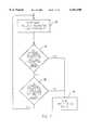
- FIG. 4is a logic diagram for the volume/temperature functions of a monitor
- FIG. 5is a logic diagram for a monitor which will issue an alarm signal when the water using device is continuously open;
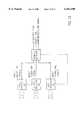
- FIG. 6is a schematic illustration of a system for a multi story building including a receiver on each floor for receiving and outputting data from the monitors on its floor;
- FIG. 7is a logic diagram for a monitor which will issue a maintenance signal when a water device is leaking;
- FIG. 8is a schematic illustration for a home system
- FIG. 9is a logic diagram for comparing the output of a common monitor with the outputs of all the dedicated monitors to identify a leak
- FIG. 10is a schematic illustration of a system for a building that has a plurality of local receivers that are hard wired in series with the base local receiver outputting data;
- FIG. 11is a schematic illustration of a system similar to that of FIG. 6, with individual local receivers hard wired or phone linked in parallel to a base local computer;
- FIG. 12is a schematic illustration of a system having a plurality of local receivers linked in series or in parallel to a remote receiver;
- FIG. 13is a schematic illustration of a system having a plurality of local and remote receivers which are linked to a data base.
- Utility provided water 10generally is metered by a water meter WM 11 as it enters a building such as an apartment house or office building. A portion of the water branches off to supply the building cold water supply line 12 and the other portion is supplied to a hot water heater H 13 which supplies the hot water supply line 14 of the building.
- the buildinghas a number of similar units (in a two story apartment house, there could be four one bedroom apartments, two on each floor, for example) each having a sink (including associated tub/shower) and toilet in the powder room and a second sink (including any associated appliances such as a dishwasher) in the kitchen.
- FIG. 2shows the heating/cooling system for the same units.
- Waterhot in the winter or cold in the summer
- HP 13Adiscrete sources such as a boiler for hot water and a chiller for cold water could be utilized
- the wateris returned to the source HP by suitable return lines 18.
- Located upstream and downstream of each heating or cooling unit H/Cis a monitor M.
- a monitor M(FIG. 3) which can be located in each line by a plumber, is a unitary battery operated structure, which is fully sealed to reduce tampering and water damage.
- the monitorcan have a universal set of fittings to simplify installation.
- a monitormay include a pipe 20 in which may be permanently secured a gearbox 21 such as the type found in lawn sprinkler heads to control the movement of the water spray.
- the gear boxhas axial input 22 and output 24 shafts which are connected to a turbine wheel drive propeller 26 and a copper or other metal axially extending partial cylindrical portion paddle wheel 28. Water entering the pipe, passes through a set of orifices 30 which direct the water at the propeller blades thereby efficiently driving the gearbox.
- the gear ratio of the gearboxis selected so that the partial cylindrical portion 28 will make no more than about half a rotation during a sampling time (a rate of rotation that will assure that an oscillator (OSC-25) will sense the presence of the partial cylindrical portion (the target) 28 twice each revolution).
- the gear ratiomay be different for different devices (full flow for a toilet is very different than full flow for a tub, for example).
- Coil 29will change inductance twice each revolution changing the frequency of the oscillator.
- the microprocessor uc 31 or custom specialized electronic circuitcan therefore count a pulse each time the target 28 is located at 0° and 180° and each pulse equates to a unit volume of liquid. Referring to FIG.
- the gear ratiowill be selected so that the target will rotate less than 180°, during one minute with maximum flow through the pipe.
- sensorssuch as a rotating magnet and Hall effect sensor, reed switch, capacitive sensor, optical sensor, inductive sensor with ferrite rotator, etc.
- the updated countis representative of the total volumetric flow through the pipe. Limiting the rate of rotation of the target with the gear box so that a reading need only be taken once per minute, prolongs battery life since the microprocessor uc only has to be turned on once per minute.
- the flow measuring systemcould also be an ultrasonic Doppler flowmeter, a magnetic flowmeter, an electronic mass flowmeter, or a vortex flowmeter, for example.
- the energy use of the hot water used in a water using devicemay be computed by multiplying the volumetric volume of the associated hot water pipe by the temperature that hot water is supplied where the monitor is receiving hot water from the hot water heater.
- the monitorcan include a heat thermistor 32 (or a thermocouple, etc.) attached to the pipe to sense the temperature of the fluid flowing through the monitor.
- the microprocessor uc 31may multiply the temperature by that unit volumetric flow to define a heat content number (BTU use--FIG. 4) and will then update the total heat content totalizator step 60.
- the energy use of the heating/cooling unitcan be determined.
- one of the monitors on either side of a heating/cooling unitcan monitor only temperature and be connected to the other monitor with that monitor making both computations such as by subtracting out the temperature reading from the other to compute the heat change. Should electrical power be available or should the battery economics permit, the position of the target could be sampled continuously and the gear box would not be required.
- the microprocessorwill operate the transmitter (which is a radio transmitter 33 in the preferred embodiment but could be an ultra sonic or infrared transmitter, etc.) to transmit the then current count of the register which is representative of volumetric flow, the then current total of the heat content totalizator, identifier data which identifies the apartment unit, the water using device, etc. and any pulse count data used to chronologically locate the transmission step 58.
- the transmitterwhich is a radio transmitter 33 in the preferred embodiment but could be an ultra sonic or infrared transmitter, etc.
- the microprocessor uccan also determine that a water consuming device has been left open (a tub running continuously, for example). For example, the microprocessor should detect the presence of the target once a minute while the tub is being filled at the fully open condition. Even at a slow fill rate the target should be sensed once every "X" minutes step 62 (FIG. 5). If "X" is five minutes, for example, the filling process should be complete within twenty minutes (four multiples of "X"). Accordingly, according to the algorithm expressed in FIG. 5, when the water has been running for "X" minutes and the target has been sensed, the counter is incremented step 64 and the process is repeated. When the target has been sensed in the next "X" minutes the counter again increments and so forth.
- step 66If the count reaches 15 ("Y") step 66, for example, the water has run for a time beyond that which was required to fill the tub and this can mean that someone has failed to turn the water off, etc. Should the microprocessor determine that flow has continued for more "Y" increments of "X", the microprocessor will direct the transmitter to transmit an alarm signal step 68, identifying the water consuming device, to the receiver which indicates that the device has been left open so that immediate action can be taken to correct the problem.
- the alarm signalcan be transmitted to a local receiver which could be a general alarm system for the home which would announce the condition or it could be further transmitted to a remote receiver which could be at a home security company which could take appropriate action or it could be a part of the water usage system for a multiple unit building as described herein.
- This algorithmcan also be computed with a number of "X” and "Y” values ("X1" and "Y1", “X2” and “Y2", for example) since the fill rate can be chosen at widely different rates. These variables can also be defined during installation by programming non volatile memory in the monitor.
- a radio (local) receiver(a microprocessor, for example) which can receive and decode the transmitted radio signal can be located on each floor (FIG. 6) for receiving the data transmitted from all of the monitors on its floor.
- the local receivermay compute daily, weekly, monthly, quarterly, etc., totals for the volumetric flow and energy (BTU) use for each unit, and can issue alarm signals (by audible alarm or telephone to a security location, for example, identifying the unit and the water consuming device subject to the alarm signal.
- Each receivercould, for example, have a visual readout or it could be connectable to a hand held terminal which can read out the data.
- the local receivermay also implement the algorithm disclosed in FIG. 7. It can determine a rolling volumetric flow average/unit of time step 70 ("T" may be 30 or 60 days for example) and first compare that with the calculated current volumetric flow/unit of time step 72. Where it exceeds the rolling average by X% which indicates the a faucet is leaking, for example, the local receiver will send a maintenance signal step 74. A second comparison can also be made to determine whether the current volumetric flow/unit of time exceeds by Y% a standard for that device step 76. Should the difference exceed this variance, the local receiver will issue a maintenance signal.
- Trolling volumetric flow average/unit of time step 70
- X%which indicates the a faucet is leaking
- the local receiverwill send a maintenance signal step 74.
- a second comparisoncan also be made to determine whether the current volumetric flow/unit of time exceeds by Y% a standard for that device step 76. Should the difference exceed this variance, the local receiver will issue a maintenance signal.
- the receiverin its simplest form, could contain an information system (or a part of a larger information system) for an individual unit or a home (FIG. 8).
- a monitorwhich would not have to monitor temperature, could be placed in each line supplying the water consuming devices so that volumetric flow data could be transmitted to a local receiver which would determine whether any device was leaking or open and would issue an appropriate alarm or maintenance signal for that device.
- This figurealso illustrates a monitor downstream of the water meter WM-11. This monitor can implement the algorithm of FIG. 5 to detect a break in any downstream water line such as could happen as a result of earthquake or freeze damage, for example. By comparing the volumetric flow/unit of time of this common monitor (FIG.
- step 82with the total/unit of time of all the dedicated monitors step 80, an internal leak can be identified (a variance of X% would indicate an internal leak).
- Maintenance and alarm signalscan be issued step 84 by the local receiver and optionally the local receiver can communicate with a remote receiver in the form of a security company or to the monitoring or billing system to obtain assistance.
- the multi-unit buildingmay have a plurality of local receivers hard wired in series (or connected on a phone line) to a base local receiver (the local receiver located on the superintendents' floor for example), with the base local receiver presenting the data for all the local receivers.
- a radiocustom or PCS system
- the total volumetric flow and energy use for an individual unitcan be computed by each of the local receivers or all computations can be performed by the base local receiver. Alternately, such a base local receiver can be connected in parallel with the other local receivers (FIG. 11).
- the base receivermay not receive data from a monitor but only receive data from local receivers (receivers receiving data from monitors (FIG. 12).
- the base receiveris then a remote receiver.
- the remote receiver(FIG. 13) can provide a database which communicates via phone lines with any number of local and/or remote receivers and a receiver (a local receiver, a base local receiver or a remote receiver) can operate on the data and prepare, bills for water, energy and sewer use for each reporting unit which can be sent directly to the individual units or to the buildings for distribution as well as support reporting of leaks and open faucets, etc.
Landscapes
- Business, Economics & Management (AREA)
- Physics & Mathematics (AREA)
- Engineering & Computer Science (AREA)
- General Physics & Mathematics (AREA)
- Development Economics (AREA)
- Strategic Management (AREA)
- Economics (AREA)
- Fluid Mechanics (AREA)
- Marketing (AREA)
- Finance (AREA)
- General Business, Economics & Management (AREA)
- Theoretical Computer Science (AREA)
- Accounting & Taxation (AREA)
- Combustion & Propulsion (AREA)
- Health & Medical Sciences (AREA)
- Chemical & Material Sciences (AREA)
- Public Health (AREA)
- Entrepreneurship & Innovation (AREA)
- Game Theory and Decision Science (AREA)
- Water Supply & Treatment (AREA)
- General Health & Medical Sciences (AREA)
- Human Resources & Organizations (AREA)
- Primary Health Care (AREA)
- Tourism & Hospitality (AREA)
- Electromagnetism (AREA)
- Thermal Sciences (AREA)
- Mechanical Engineering (AREA)
- General Engineering & Computer Science (AREA)
- Measuring Volume Flow (AREA)
Abstract
Description
Claims (4)
Priority Applications (8)
| Application Number | Priority Date | Filing Date | Title |
|---|---|---|---|
| US08/746,398US6161100A (en) | 1996-11-08 | 1996-11-08 | System for billing individual units of a multi-unit building for water use and for water related energy use |
| EP97308887AEP0841546B1 (en) | 1996-11-08 | 1997-11-05 | System for monitoring water consuming structures and their heat use in an individual unit of a multi-unit building and a system for billing therefor |
| DE69720139TDE69720139T2 (en) | 1996-11-08 | 1997-11-05 | System for monitoring water-consuming structures and their heat consumption in a unit or in a building containing several units, and associated billing system |
| CA002220242ACA2220242A1 (en) | 1996-11-08 | 1997-11-05 | System for monitoring water consuming structures and their heat use in an individual unit of a multi-unit building and a system for billing therefor |
| EP02077285AEP1267148A3 (en) | 1996-11-08 | 1997-11-05 | System for monitoring water consuming structures and their heat use in an individual unit of a multi-unit building and a system for billing therefor |
| SG200102641ASG121690A1 (en) | 1996-11-08 | 1997-11-06 | System for monitoring water consuming structures and their heat use in an individual unit of a multi-unit building and a system for building therefor |
| MXPA/A/1997/008550AMXPA97008550A (en) | 1996-11-08 | 1997-11-06 | System for monitoring the structures of water consumption and its use of heat, in an individual unit of a multiple unit building, and a billing system for |
| SG1997003971ASG71057A1 (en) | 1996-11-08 | 1997-11-06 | System for monitoring water consuming structures and their heat use in an individual unit of a multi-unit building and a system for billing therefor |
Applications Claiming Priority (1)
| Application Number | Priority Date | Filing Date | Title |
|---|---|---|---|
| US08/746,398US6161100A (en) | 1996-11-08 | 1996-11-08 | System for billing individual units of a multi-unit building for water use and for water related energy use |
Publications (1)
| Publication Number | Publication Date |
|---|---|
| US6161100Atrue US6161100A (en) | 2000-12-12 |
Family
ID=25000671
Family Applications (1)
| Application Number | Title | Priority Date | Filing Date |
|---|---|---|---|
| US08/746,398Expired - Fee RelatedUS6161100A (en) | 1996-11-08 | 1996-11-08 | System for billing individual units of a multi-unit building for water use and for water related energy use |
Country Status (1)
| Country | Link |
|---|---|
| US (1) | US6161100A (en) |
Cited By (33)
| Publication number | Priority date | Publication date | Assignee | Title |
|---|---|---|---|---|
| US20020091653A1 (en)* | 1997-12-19 | 2002-07-11 | Michael R. Peevey | Method and apparatus for metering electricity usage and electronically providing information associated therewith |
| US6430514B1 (en)* | 2000-10-26 | 2002-08-06 | David A. Saar | Water management system |
| WO2002077580A1 (en)* | 2001-03-22 | 2002-10-03 | Fernando Milanes Garcia-Moreno | Electronic and mechanical system for automated or discretionary dosage of potable water at the particular intake level of each user |
| US20040073524A1 (en)* | 2002-10-15 | 2004-04-15 | Smith Wade W. | Water metering system |
| US20050190066A1 (en)* | 2003-10-16 | 2005-09-01 | Mike Schleich | Consumptive leak detection system |
| US20060012491A1 (en)* | 2004-07-14 | 2006-01-19 | Mahowald Peter H | Utility meter reading system |
| US20060137090A1 (en)* | 2004-12-29 | 2006-06-29 | Jeffries William W | Wireless water flow monitoring and leak detection system, and method |
| US20060245467A1 (en)* | 2005-04-08 | 2006-11-02 | Casella Michael H | Apparatus, system and method for monitoring, recording and billing for individual fixture and unit water usage in a multi-unit structure |
| US20070103335A1 (en)* | 2005-10-20 | 2007-05-10 | Fitzgerald Aaron J | Automatic detection of unusual consumption by a utility meter |
| WO2007071330A1 (en)* | 2005-12-20 | 2007-06-28 | M & Fc Holding Llc | Consumption meter |
| US20070160108A1 (en)* | 2004-03-03 | 2007-07-12 | Richard Kent | Self-heated thermistor control circuit |
| US20070246551A1 (en)* | 2004-08-26 | 2007-10-25 | Phillips Terry G | Modular control system and method for water heaters |
| US20080180274A1 (en)* | 2004-01-14 | 2008-07-31 | Itron, Inc. | Method and apparatus for collecting and displaying consumption data a from a meter reading system |
| US20100082134A1 (en)* | 2004-08-26 | 2010-04-01 | Phillips Terry G | Modular control system and method for a water heater |
| US20110077791A1 (en)* | 2009-09-30 | 2011-03-31 | Sanyo Electric Co., Ltd. | Electrical equipment management system |
| US20110246342A1 (en)* | 2009-09-28 | 2011-10-06 | Simple Bills, Inc. | Consolidated invoicing and payment system for communities of multiple members |
| CN102571917A (en)* | 2010-12-02 | 2012-07-11 | 马斯科公司 | Water usage monitoring system |
| US8428891B2 (en) | 2010-11-10 | 2013-04-23 | Hp Ventures A/S | Systems and methods for apportioning usage of a utility in a multi-unit building |
| FR2993976A1 (en)* | 2012-07-30 | 2014-01-31 | Oxena Conseil | SYSTEM FOR ESTIMATING INDIVIDUAL WATER CONSUMPTION |
| US8740177B2 (en) | 2011-07-05 | 2014-06-03 | Rain Bird Corporation | Eccentric diaphragm valve |
| EA024514B1 (en)* | 2013-12-25 | 2016-09-30 | Павел Эдуардович МЕЛЬНИКОВ | Heat metering system for single-pipe vertical heating system in building or structure |
| US9506785B2 (en) | 2013-03-15 | 2016-11-29 | Rain Bird Corporation | Remote flow rate measuring |
| US20170069040A1 (en)* | 2015-09-04 | 2017-03-09 | 2481679 Ontario Inc. | Engineered multi-unit heating and cooling energy monitoring and cost allocation system |
| US10235724B2 (en) | 2016-06-01 | 2019-03-19 | International Business Machines Corporation | Energy efficient hot water distribution |
| EP3485231A4 (en)* | 2016-07-18 | 2019-07-10 | Vaughn Realty Ventures LLC | WATER MEASURING SYSTEM |
| US10473494B2 (en) | 2017-10-24 | 2019-11-12 | Rain Bird Corporation | Flow sensor |
| US10634538B2 (en) | 2016-07-13 | 2020-04-28 | Rain Bird Corporation | Flow sensor |
| US11662242B2 (en) | 2018-12-31 | 2023-05-30 | Rain Bird Corporation | Flow sensor gauge |
| WO2023141674A1 (en)* | 2022-01-25 | 2023-08-03 | Taouk Fadi | A metering method and device |
| US11821770B2 (en) | 2016-07-18 | 2023-11-21 | Vaughn Realty Ventures LLC | Water metering system |
| CN117723124A (en)* | 2023-09-15 | 2024-03-19 | 东岱(济南)智能技术有限公司 | Water meter assembly for monitoring water consumption abnormality of user based on wireless transmission |
| US12222231B2 (en) | 2016-07-18 | 2025-02-11 | Vaughn Realty Ventures LLC | Water metering system |
| US12443208B2 (en) | 2023-02-08 | 2025-10-14 | Rain Bird Corporation | Control zone devices, systems and methods |
Citations (16)
| Publication number | Priority date | Publication date | Assignee | Title |
|---|---|---|---|---|
| US3747082A (en)* | 1971-08-23 | 1973-07-17 | M & J Valve Co | Systems with constant current generators for transmitting flow rate data |
| US4002890A (en)* | 1974-08-01 | 1977-01-11 | Einar Welins Patenter Kommanditbolag | Method of charging fuel costs among the various apartments in an apartment house or the like and suitable devices in this connection |
| US4304127A (en)* | 1979-06-29 | 1981-12-08 | Wilgood Corporation | Measurement of delivered thermal units |
| US4306293A (en)* | 1979-08-30 | 1981-12-15 | Marathe Sharad M | Energy monitoring system |
| US4363441A (en)* | 1980-04-23 | 1982-12-14 | Emanuel Feinberg | Thermal energy usage meter for multiple unit building |
| US4558958A (en)* | 1984-02-02 | 1985-12-17 | Pena Jose C | Energy consumption indicating system |
| US4577977A (en)* | 1985-04-01 | 1986-03-25 | Honeywell Inc. | Energy submetering system |
| US4940976A (en)* | 1988-02-05 | 1990-07-10 | Utilicom Inc. | Automated remote water meter readout system |
| US5053766A (en)* | 1987-04-23 | 1991-10-01 | Iberduero, S.A. | Telemetering system for electrical power consumed by various users |
| US5079715A (en)* | 1987-12-28 | 1992-01-07 | Krishnan Venkataraman | Electronic data recorder for electric energy metering |
| US5111407A (en)* | 1989-08-25 | 1992-05-05 | Arad Ltd. | System for measuring and recording a utility consumption |
| US5153837A (en)* | 1990-10-09 | 1992-10-06 | Sleuth Inc. | Utility consumption monitoring and control system |
| US5283572A (en)* | 1990-08-17 | 1994-02-01 | Communications Instruments Inc. | Utility meter interface circuit |
| US5404136A (en)* | 1988-08-23 | 1995-04-04 | Marsden; Derek R. | Method and apparatus for monitoring the consumption of utilities in business premises |
| US5565862A (en)* | 1995-03-28 | 1996-10-15 | The Titan Corporation | Collection and management of pipeline-flow data |
| US5646858A (en)* | 1994-03-10 | 1997-07-08 | Analytical Systems Engineering Corp. | Heat apportionment system |
- 1996
- 1996-11-08USUS08/746,398patent/US6161100A/ennot_activeExpired - Fee Related
Patent Citations (16)
| Publication number | Priority date | Publication date | Assignee | Title |
|---|---|---|---|---|
| US3747082A (en)* | 1971-08-23 | 1973-07-17 | M & J Valve Co | Systems with constant current generators for transmitting flow rate data |
| US4002890A (en)* | 1974-08-01 | 1977-01-11 | Einar Welins Patenter Kommanditbolag | Method of charging fuel costs among the various apartments in an apartment house or the like and suitable devices in this connection |
| US4304127A (en)* | 1979-06-29 | 1981-12-08 | Wilgood Corporation | Measurement of delivered thermal units |
| US4306293A (en)* | 1979-08-30 | 1981-12-15 | Marathe Sharad M | Energy monitoring system |
| US4363441A (en)* | 1980-04-23 | 1982-12-14 | Emanuel Feinberg | Thermal energy usage meter for multiple unit building |
| US4558958A (en)* | 1984-02-02 | 1985-12-17 | Pena Jose C | Energy consumption indicating system |
| US4577977A (en)* | 1985-04-01 | 1986-03-25 | Honeywell Inc. | Energy submetering system |
| US5053766A (en)* | 1987-04-23 | 1991-10-01 | Iberduero, S.A. | Telemetering system for electrical power consumed by various users |
| US5079715A (en)* | 1987-12-28 | 1992-01-07 | Krishnan Venkataraman | Electronic data recorder for electric energy metering |
| US4940976A (en)* | 1988-02-05 | 1990-07-10 | Utilicom Inc. | Automated remote water meter readout system |
| US5404136A (en)* | 1988-08-23 | 1995-04-04 | Marsden; Derek R. | Method and apparatus for monitoring the consumption of utilities in business premises |
| US5111407A (en)* | 1989-08-25 | 1992-05-05 | Arad Ltd. | System for measuring and recording a utility consumption |
| US5283572A (en)* | 1990-08-17 | 1994-02-01 | Communications Instruments Inc. | Utility meter interface circuit |
| US5153837A (en)* | 1990-10-09 | 1992-10-06 | Sleuth Inc. | Utility consumption monitoring and control system |
| US5646858A (en)* | 1994-03-10 | 1997-07-08 | Analytical Systems Engineering Corp. | Heat apportionment system |
| US5565862A (en)* | 1995-03-28 | 1996-10-15 | The Titan Corporation | Collection and management of pipeline-flow data |
Cited By (51)
| Publication number | Priority date | Publication date | Assignee | Title |
|---|---|---|---|---|
| US7043459B2 (en)* | 1997-12-19 | 2006-05-09 | Constellation Energy Group, Inc. | Method and apparatus for metering electricity usage and electronically providing information associated therewith |
| US20020091653A1 (en)* | 1997-12-19 | 2002-07-11 | Michael R. Peevey | Method and apparatus for metering electricity usage and electronically providing information associated therewith |
| US6430514B1 (en)* | 2000-10-26 | 2002-08-06 | David A. Saar | Water management system |
| WO2002077580A1 (en)* | 2001-03-22 | 2002-10-03 | Fernando Milanes Garcia-Moreno | Electronic and mechanical system for automated or discretionary dosage of potable water at the particular intake level of each user |
| US20040199476A1 (en)* | 2001-03-22 | 2004-10-07 | Fernando Milanes Garcia-Moreno | Electronic and mechanical system for automated or discretionay dosage of potable water at the particular intake level of each user |
| US8719187B2 (en) | 2001-03-22 | 2014-05-06 | Fernando Milanes Garcia-Moreno | Electronic and mechanical system for automated or discretionay dosage of potable water at the particular intake level of each user |
| US20040073524A1 (en)* | 2002-10-15 | 2004-04-15 | Smith Wade W. | Water metering system |
| US7119698B2 (en)* | 2003-10-16 | 2006-10-10 | Itron, Inc. | Consumptive leak detection system |
| US20050190066A1 (en)* | 2003-10-16 | 2005-09-01 | Mike Schleich | Consumptive leak detection system |
| US20080180274A1 (en)* | 2004-01-14 | 2008-07-31 | Itron, Inc. | Method and apparatus for collecting and displaying consumption data a from a meter reading system |
| US20070160108A1 (en)* | 2004-03-03 | 2007-07-12 | Richard Kent | Self-heated thermistor control circuit |
| US7607823B2 (en)* | 2004-03-03 | 2009-10-27 | Waters Technologies Corporation | Leak detector comprising a self-heated thermistor control circuit |
| US20060012491A1 (en)* | 2004-07-14 | 2006-01-19 | Mahowald Peter H | Utility meter reading system |
| US20100082134A1 (en)* | 2004-08-26 | 2010-04-01 | Phillips Terry G | Modular control system and method for a water heater |
| US8977791B2 (en) | 2004-08-26 | 2015-03-10 | A. O. Smith Corporation | Modular control system and method for a water heater |
| US20070246551A1 (en)* | 2004-08-26 | 2007-10-25 | Phillips Terry G | Modular control system and method for water heaters |
| US8660701B2 (en) | 2004-08-26 | 2014-02-25 | A. O. Smith Corporation | Modular control system and method for water heaters |
| US9057534B2 (en) | 2004-08-26 | 2015-06-16 | A. O. Smith Corporation | Modular control system and method for water heaters |
| US10240817B2 (en) | 2004-08-26 | 2019-03-26 | A. O. Smith Corporation | Modular control system and method for water heaters |
| US7360413B2 (en) | 2004-12-29 | 2008-04-22 | Water Cents, Llc | Wireless water flow monitoring and leak detection system, and method |
| US20060137090A1 (en)* | 2004-12-29 | 2006-06-29 | Jeffries William W | Wireless water flow monitoring and leak detection system, and method |
| US7508318B2 (en)* | 2005-04-08 | 2009-03-24 | H20Flo, Llc | Apparatus, system and method for monitoring, recording and billing for individual fixture and unit water usage in a multi-unit structure |
| US20060245467A1 (en)* | 2005-04-08 | 2006-11-02 | Casella Michael H | Apparatus, system and method for monitoring, recording and billing for individual fixture and unit water usage in a multi-unit structure |
| US20070103335A1 (en)* | 2005-10-20 | 2007-05-10 | Fitzgerald Aaron J | Automatic detection of unusual consumption by a utility meter |
| WO2007071330A1 (en)* | 2005-12-20 | 2007-06-28 | M & Fc Holding Llc | Consumption meter |
| US20110246342A1 (en)* | 2009-09-28 | 2011-10-06 | Simple Bills, Inc. | Consolidated invoicing and payment system for communities of multiple members |
| US20110077791A1 (en)* | 2009-09-30 | 2011-03-31 | Sanyo Electric Co., Ltd. | Electrical equipment management system |
| US8649913B2 (en)* | 2009-09-30 | 2014-02-11 | Sanyo Electric Co., Ltd. | Electrical equipment management system |
| US8428891B2 (en) | 2010-11-10 | 2013-04-23 | Hp Ventures A/S | Systems and methods for apportioning usage of a utility in a multi-unit building |
| US8909488B2 (en) | 2010-11-10 | 2014-12-09 | Hp Ventures A/S | Systems and methods for apportioning usage of a utility in a multi-unit building |
| CN102571917A (en)* | 2010-12-02 | 2012-07-11 | 马斯科公司 | Water usage monitoring system |
| US8740177B2 (en) | 2011-07-05 | 2014-06-03 | Rain Bird Corporation | Eccentric diaphragm valve |
| FR2993976A1 (en)* | 2012-07-30 | 2014-01-31 | Oxena Conseil | SYSTEM FOR ESTIMATING INDIVIDUAL WATER CONSUMPTION |
| US9719828B2 (en) | 2012-07-30 | 2017-08-01 | Oxena Conseil | System for estimating individual water consumption |
| WO2014020252A1 (en)* | 2012-07-30 | 2014-02-06 | Oxena Conseil | System for estimating individual water consumption |
| US9506785B2 (en) | 2013-03-15 | 2016-11-29 | Rain Bird Corporation | Remote flow rate measuring |
| EA024514B1 (en)* | 2013-12-25 | 2016-09-30 | Павел Эдуардович МЕЛЬНИКОВ | Heat metering system for single-pipe vertical heating system in building or structure |
| US20170069040A1 (en)* | 2015-09-04 | 2017-03-09 | 2481679 Ontario Inc. | Engineered multi-unit heating and cooling energy monitoring and cost allocation system |
| US10055800B2 (en)* | 2015-09-04 | 2018-08-21 | 2481679 Ontario Inc. | Engineered multi-unit heating and cooling energy monitoring and cost allocation system |
| US10235724B2 (en) | 2016-06-01 | 2019-03-19 | International Business Machines Corporation | Energy efficient hot water distribution |
| US10634538B2 (en) | 2016-07-13 | 2020-04-28 | Rain Bird Corporation | Flow sensor |
| US11821770B2 (en) | 2016-07-18 | 2023-11-21 | Vaughn Realty Ventures LLC | Water metering system |
| EP3485231A4 (en)* | 2016-07-18 | 2019-07-10 | Vaughn Realty Ventures LLC | WATER MEASURING SYSTEM |
| US11221245B2 (en) | 2016-07-18 | 2022-01-11 | Vaughn Realty Ventures LLC | Water metering system |
| US12222231B2 (en) | 2016-07-18 | 2025-02-11 | Vaughn Realty Ventures LLC | Water metering system |
| US10473494B2 (en) | 2017-10-24 | 2019-11-12 | Rain Bird Corporation | Flow sensor |
| US11662242B2 (en) | 2018-12-31 | 2023-05-30 | Rain Bird Corporation | Flow sensor gauge |
| WO2023141674A1 (en)* | 2022-01-25 | 2023-08-03 | Taouk Fadi | A metering method and device |
| AU2023210685B2 (en)* | 2022-01-25 | 2024-05-02 | Commet Industries Pty Ltd | A metering method and device |
| US12443208B2 (en) | 2023-02-08 | 2025-10-14 | Rain Bird Corporation | Control zone devices, systems and methods |
| CN117723124A (en)* | 2023-09-15 | 2024-03-19 | 东岱(济南)智能技术有限公司 | Water meter assembly for monitoring water consumption abnormality of user based on wireless transmission |
Similar Documents
| Publication | Publication Date | Title |
|---|---|---|
| US6161100A (en) | System for billing individual units of a multi-unit building for water use and for water related energy use | |
| US5838258A (en) | System for monitoring the use of heat energy in water devices in an individual unit of a multi-unit building | |
| US6377190B1 (en) | System for monitoring water consuming structures in an individual unit of a multi-unit building | |
| EP0841546B1 (en) | System for monitoring water consuming structures and their heat use in an individual unit of a multi-unit building and a system for billing therefor | |
| US10775213B2 (en) | Devices and system for channeling and automatic monitoring of fluid flow in fluid distribution systems | |
| US11047115B2 (en) | Water meter system and method | |
| US20210381207A1 (en) | Water meter system and method | |
| US9874466B2 (en) | Methods and apparatus for ultrasonic fluid flow measurement and fluid flow data analysis | |
| US20110035063A1 (en) | Water Management System | |
| EP2450669A1 (en) | Systems and methods for apportioning usage of a utility in a multi-unit building | |
| WO2007053091A1 (en) | A device and a method for measurement of energy for heating tap water separated from the building's heating energy-usage . | |
| AU671123B2 (en) | Flow detecting systems | |
| US6101451A (en) | Water management system | |
| EP3279612A1 (en) | Smart water monitoring device | |
| WO2017078545A1 (en) | Ultrasonic flow meter for use in or near a valve assembly | |
| EP1411329A2 (en) | Water metering system | |
| Amith et al. | IoT based smart water meter for water management | |
| MXPA97008550A (en) | System for monitoring the structures of water consumption and its use of heat, in an individual unit of a multiple unit building, and a billing system for | |
| Anglani et al. | Energy smart meters integration in favor of the end user | |
| RU15775U1 (en) | AUTOMATED SYSTEM FOR MEASURING, ACCOUNTING AND REGULATING THE COSTS OF THE HEAT CARRIER FOR HEAT SUPPLY OF THE CONSUMER GROUP | |
| CN215117257U (en) | Community Internet of things water quality monitoring water meter centralized control system | |
| EP4522813A1 (en) | Water monitoring and management system in distribution networks | |
| US6430514B1 (en) | Water management system | |
| KR20250121693A (en) | Indoor water leak detection device and indoor water leak detection method for digital water meter | |
| KR20250119829A (en) | Water leakage display and transmission device for mechanical water meter and method for displaying and transmitting water leakage amount using the same |
Legal Events
| Date | Code | Title | Description |
|---|---|---|---|
| FPAY | Fee payment | Year of fee payment:4 | |
| SULP | Surcharge for late payment | ||
| AS | Assignment | Owner name:NTH POWER TECHNOLOGIES FUND II, L.P., CALIFORNIA Free format text:SECURITY AGREEMENT;ASSIGNOR:WELLSPRING INTERNATIONAL, INC.;REEL/FRAME:015698/0971 Effective date:20050224 Owner name:NORTH ATLANTIC VENTURE FUND III A LIMITED PARTNERS Free format text:SECURITY AGREEMENT;ASSIGNOR:WELLSPRING INTERNATIONAL, INC.;REEL/FRAME:015698/0971 Effective date:20050224 Owner name:EXPANSION CAPITAL PARTNERS, LLC, CALIFORNIA Free format text:SECURITY AGREEMENT;ASSIGNOR:WELLSPRING INTERNATIONAL, INC.;REEL/FRAME:015698/0971 Effective date:20050224 Owner name:CLEAN TECHNOLOGY FUND I, LP, CALIFORNIA Free format text:SECURITY AGREEMENT;ASSIGNOR:WELLSPRING INTERNATIONAL, INC.;REEL/FRAME:015698/0971 Effective date:20050224 | |
| AS | Assignment | Owner name:SAN DIEGO WHOLESALE CREDIT ASSOCIATION, CALIFORNIA Free format text:ASSIGNMENT OF ASSIGNORS INTEREST;ASSIGNOR:WELLSPRING INTERNATIONAL, INC.;REEL/FRAME:015778/0537 Effective date:20050304 Owner name:WELLSPRING ACQUISITION, INC., PENNSYLVANIA Free format text:ASSIGNMENT OF ASSIGNORS INTEREST;ASSIGNOR:SAN DIEGO WHOLESALE CREDIT ASSOCIATION;REEL/FRAME:015778/0560 Effective date:20050304 | |
| AS | Assignment | Owner name:WELLSPRING WIRELESS, INC., PENNSYLVANIA Free format text:ASSIGNMENT OF ASSIGNORS INTEREST;ASSIGNOR:WELLSPRING ACQUISITION, INC.;REEL/FRAME:019084/0145 Effective date:20070323 | |
| REMI | Maintenance fee reminder mailed | ||
| LAPS | Lapse for failure to pay maintenance fees | ||
| STCH | Information on status: patent discontinuation | Free format text:PATENT EXPIRED DUE TO NONPAYMENT OF MAINTENANCE FEES UNDER 37 CFR 1.362 | |
| FP | Lapsed due to failure to pay maintenance fee | Effective date:20081212 |