US6160548A - Method and mechanism for synchronizing hardware and software modules - Google Patents
Method and mechanism for synchronizing hardware and software modulesDownload PDFInfo
- Publication number
- US6160548A US6160548AUS08/842,552US84255297AUS6160548AUS 6160548 AUS6160548 AUS 6160548AUS 84255297 AUS84255297 AUS 84255297AUS 6160548 AUS6160548 AUS 6160548A
- Authority
- US
- United States
- Prior art keywords
- time
- information
- state
- clock
- logical clock
- Prior art date
- Legal status (The legal status is an assumption and is not a legal conclusion. Google has not performed a legal analysis and makes no representation as to the accuracy of the status listed.)
- Expired - Lifetime
Links
Images


Classifications
- H—ELECTRICITY
- H04—ELECTRIC COMMUNICATION TECHNIQUE
- H04N—PICTORIAL COMMUNICATION, e.g. TELEVISION
- H04N5/00—Details of television systems
- H04N5/04—Synchronising
- H04N5/06—Generation of synchronising signals
- H04N5/067—Arrangements or circuits at the transmitter end
- H04N5/073—Arrangements or circuits at the transmitter end for mutually locking plural sources of synchronising signals, e.g. studios or relay stations
- G—PHYSICS
- G11—INFORMATION STORAGE
- G11B—INFORMATION STORAGE BASED ON RELATIVE MOVEMENT BETWEEN RECORD CARRIER AND TRANSDUCER
- G11B27/00—Editing; Indexing; Addressing; Timing or synchronising; Monitoring; Measuring tape travel
- G11B27/002—Programmed access in sequence to a plurality of record carriers or indexed parts, e.g. tracks, thereof, e.g. for editing
- G—PHYSICS
- G11—INFORMATION STORAGE
- G11B—INFORMATION STORAGE BASED ON RELATIVE MOVEMENT BETWEEN RECORD CARRIER AND TRANSDUCER
- G11B27/00—Editing; Indexing; Addressing; Timing or synchronising; Monitoring; Measuring tape travel
- G11B27/02—Editing, e.g. varying the order of information signals recorded on, or reproduced from, record carriers
- G11B27/031—Electronic editing of digitised analogue information signals, e.g. audio or video signals
- G11B27/034—Electronic editing of digitised analogue information signals, e.g. audio or video signals on discs
- G—PHYSICS
- G11—INFORMATION STORAGE
- G11B—INFORMATION STORAGE BASED ON RELATIVE MOVEMENT BETWEEN RECORD CARRIER AND TRANSDUCER
- G11B27/00—Editing; Indexing; Addressing; Timing or synchronising; Monitoring; Measuring tape travel
- G11B27/10—Indexing; Addressing; Timing or synchronising; Measuring tape travel
- G11B27/34—Indicating arrangements
- H—ELECTRICITY
- H04—ELECTRIC COMMUNICATION TECHNIQUE
- H04N—PICTORIAL COMMUNICATION, e.g. TELEVISION
- H04N5/00—Details of television systems
- H04N5/04—Synchronising
Definitions
- the inventionrelates generally to the computer-based control of audiovisual devices, and more particularly to a method and mechanism for synchronizing hardware and software modules with respect to audiovisual devices.
- Digital nonlinear video editorsare sophisticated tools which assist in the development of creative audiovisual productions.
- a digital non-linear editorallows individual frames or clips of video from one or more sources to be individually edited and assembled into an elaborate video production. Audio can be combined therewith and modified as desired to produce a complete audiovisual production.
- One such digital nonlinear editoris described in U.S. patent application Ser. No. 08/771,447, filed Dec. 20, 1996 and assigned to the assignee of the present invention.
- the various audiovisual devices connected to a digital nonlinear video editoroperate independent of one another.
- a videotape player and an audio playermay each have modules with time counters associated therewith, but provide no way to synchronize the counter of one with the counter of the other.
- the video playermay not directly possess a time counter, but instead may be arranged to work with frames of information intended to be serially displayed at a predetermined frequency.
- the starting point for one devicemay be offset from the starting point for another.
- the desired video information for a video clipmay begin at one-hour on the videotape while the desired audio information begins at thirteen minutes on its tape.
- the time required for one device to rewind and/or thread a tape and begin prerolling the tape to stabilize itself for playbackmay be entirely different from the time needed by another device, such as a device that stores its information in high-speed RAM.
- synchronization of the various devicesis difficult to accomplish and maintain.
- a digital nonlinear editornot only needs to start its connected devices precisely in synchronization, but must also be able to rewind, play and fast forward devices in regular, scrub, loop and step modes all while maintaining the precise synchronization.
- a desirable non-linear editorneeds to provide a user-friendly interface which may include independent software modules, each of which also need to be precisely synchronized with each other and the audiovisual devices.
- a hardware-based devicesuch as a black-burst generator provides a highly reference timing signal, but there is no way to get the devices to align with the signals.
- a related objectiveis to incorporate the method and mechanism into a digital non-linear editor.
- Another objectiveis to provide such a method and mechanism that are capable of synchronizing modules organized with different units, different offsets and/or different rewinding, threading or preroll requirements.
- Another objectiveis to provide a method and mechanism of the above kind that can align devices with an external hardware signal, while being relatively inexpensive, flexible and extensible to future developments.
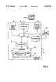
- FIG. 1is a block diagram representing a computer system in which the present invention may be incorporated;
- FIG. 2is a block diagram representing components in the computer system storage and the devices connected thereto for implementing the present invention
- FIG. 3is a simplified representation of a user interface for controlling certain components of FIG. 2;
- FIG. 4is a timeline of events for a clock and two exemplary synchronization ports operating in accordance with one aspect of the present invention
- FIG. 5is a flow diagram corresponding to the events in FIG. 4 and representing the steps taken by the clock, synchronization manager and the two exemplary synchronization ports to synchronize modules;
- FIG. 6is a block diagram representing components in the computer system storage including an alternative interface and the devices connected thereto for implementing the present invention.
- the computer system 20includes a processor 22 operatively connected to a storage 24, the storage including random access memory (RAM) 26 and non-volatile storage 28 such as a hard disk-drive, optical drive or the like.
- RAMrandom access memory
- non-volatile storage 28such as a hard disk-drive, optical drive or the like.
- the non-volatile storage 28can be used in conjunction with the RAM 26 to provide a relatively large amount of virtual memory via well-known swapping techniques.
- the computer system 20also includes at least one input device 30, typically a keyboard and/or a pointing device such as a mouse, connected through input-output circuitry (I/O) 32 for communicating user commands to the processor 22.
- I/Oinput-output circuitry
- at least one local output device 34such as a computer display monitor and speakers are connected to the I/O 32 for communicating information from the processor 22 to the user of the system 20.
- the computer system 20typically includes appropriate interface circuitry 36 for providing signals to an external high-speed digital television (e.g., NTSC) monitor 38.
- the external monitor 38enables an author/editor to view a series of video frames with the rate, interlacing, aspect ratio and so on of consumer video equipment, so that the edited video accurately represents what the viewer will ultimately see.
- the computer system 20also includes appropriate interface circuitry 40 for communicating with external audiovisual hardware devices 42 1 -42 n (FIG. 2).
- such devices 42 1 -42 nmay include videocassette recorders, laserdisc players, CD-ROM players and the like.
- Such devicesare typically professional-quality machines, and thus are capable of receiving and precisely acting on commands (e.g., advance to a specified frame or relative time) and outputting status information (e.g., the machine is currently positioned at a specified frame or time).
- the devices 42 1 -42 ninclude serial ports, local-area-network adapter cards or the like whereby such information may be passed to and from the computer system 20. In any event, such connections are known and are not described in detail herein.
- Each machineis thus considered to have a hardware and/or software module 42 1 -42 n through which the information is exchanged with the computer system 20.
- one software module 46may generate a play cursor 48 (FIG. 3) on the computer display 34 which visibly indicates the overall position relative to a timeline 50 in an audiovisual presentation.
- Another module 52may generate a time counter 54 (FIG. 3) on the display 36.
- the two modules 46, 52are independent of one another, yet are synchronized in accordance with the present invention. Note that such internal modules may be considered equivalent to other audiovisual devices in that they provide the user-editor with audiovisual information corresponding to the audiovisual production being edited.
- Softimage's Digital Studio productruns on a Microsoft Windows NT 4.0 platform and provides a sophisticated non-linear editor with a number of advanced editing features and capabilities, including the synchronization aspects of the present invention as set forth herein.
- the computer system storage 24includes a number of instantiated objects and persistent data for other objects as understood in object-oriented technology.
- objectsare data structures that exhibit certain characteristics, including inheritance, polymorphism and encapsulation.
- Objectsinclude methods and data, and thus the objects shown herein provide a number of methods that may be called on by the other objects for passing information to accomplish the synchronization.
- a logical clock 62is a named object containing a high-resolution clock, preferably a 64-bit doubleword containing a tick count.
- the clock 62has various states including running, stopped, fast, and step. It also has a scale indicating the speed at which it is running, with 1.0 indicating normal speed relative to a real-time clock. Negative numbers indicate that the clock 62 is running backwards, numbers between 0 and 1.0 indicate slower than normal, and numbers above 1.0 indicating faster than normal.
- the scalecan be changed and/or the clock 62 can be interrogated to obtain its running scale.
- more than one logical clockmay be defined, but generally only one is active at a given moment.
- Each logical clockcan represent a device or a group of devices that share a common set of synchronization properties. However, for purposes of simplicity herein, generally only one logical clock will be described.
- the clock object 62includes the following data, with default values in parentheses, as set forth in the table below.
- pParentis a pointer to the parent synchronization manager 60 which created the clock object 62
- pszNameis the name of the clock object 62:
- the clock statesinclude the states set forth in the following table:
- the clock 62is named, allowing the simultaneous existence of multiple clock objects and differentiation therebetween by other software components.
- the naming of clocksalso allows the various software components to connect to the clock in a standard manner.
- the logical clock 62connects to each module via a synchronization port 64 1 -64 n , each of which is also an object.
- the synchronization manager 60opens synchronization ports and tracks the association of the ports with the named clock object 62, creating an instance of a named clock object if one does not already exist.
- modules through their synchronization portsmay be connected to a plurality of clocks at one time.
- Each synchronization port 64 1 -64 nallows the clock 62 to be viewed by its respective module using logical units specified by the module. For example one module might view the clock in seconds while another views the clock in video frames, but the underlying logical clock object 62 is the same.
- each synchronization port object 64 1 -64 nincludes methods for receiving unit information from the module connected thereto, receiving the clock tick value from the clock object, and for converting the received clock value into the appropriate value specified by the corresponding module.
- frame ratessuch as NTSC (29.97 frames/second), PAL (25 frames/second), film (24 frames/second) or any custom frame rate supported by an external device.
- Each synchronization port 64 1 -64 nalso allows its corresponding module to view the clock 62 with different logical offsets.
- the time counter module 52may be displaying zero while a tape player has its tape positioned at one hour (as output by the module of the tape player).
- the various methods of the synchronization portadjust the time values of the clock object 62 based on the offset values specified by its corresponding module (including the software modules controlled by the user of the non-linear program editor).
- the modules 44 1 -44 n and 46, 52can receive notification of certain events, including when the state of the clock 62 changes, when the clock time or scale changes, or when a given state or time is reached by the clock 62.
- the modulesspecify those state changes and properties for which they desire notification to the synchronization manager 60 via their respective synchronization port.
- the modulescan also choose to be notified of time changes in three different fashions, 1) when an absolute time is reached during a playback, 2) periodically during a playback (where the period is defined by the module), or 3) whenever the clock's time is changed while the clock is in a stopped state.
- the clock 62provides synchronization support to the otherwise independent modules. In general, synchronization is achieved by allowing the modules to query the clock 62 for its current time, state or the value of a property thereof. The modules 44 1 -44 n and 46, 52 can also be notified of changes to these states or properties.
- the logical clock 62runs in a free-threaded environment and thus allows for asynchronous access and notifications. As set forth below, the logical clock 62 in conjunction with the synchronization manager 60 maintains the current state, time, lists of clients, transition requests, notifications and other various properties needed to provide synchronization services to the modules.
- clock preparatory stateswhich enable hardware devices to physically transition between their own active and inactive modes. For example, when changing from STOP to PLAY, many tape players require time to rewind to a preroll point (and possibly thread a tape onto the heads) and begin rolling the tape (e.g., for stabilization purposes) before the players can properly output signals from the tape.
- the clock 62transitions from a stopped state to an active state, the clock 62 first enters a running transition state.
- the transition stateis known as PREPLAY when the inactive state is STOP and the clock 62 is transitioning to the active state of PLAY.
- the clock 62enters a similar state known as PRESTOP when transitioning from an active state (such as PLAY) to STOP.
- the preparatory stateis indicated to all the modules connected via the synchronization ports.
- the preparatory statesallow the various modules to prepare themselves for the next state.
- the modules 44 1 -44 n and 46, 52may take as long as they need to prepare themselves, and only when all of the modules have indicated via the synchronization ports that they are ready, will the logical clock transition itself and the modules connected thereto to the next state. For example, in the case of moving from STOP to PLAY via PREPLAY, only when the modules have properly transitioned to their own PREPLAY (or equivalent) states and have indicated this to their respective synchronization ports will the clock 62 move to the next state.
- an alternative to waiting for all synchronization ports to indicate a ready stateis to have a selective registration and notification system, wherein only certain modules register for notification of a given preparatory state, and only those registered modules need to indicate their readiness before the next state is entered.
- the preparatory statesensure that all of the modules start or stop at the same time, which is significant when synchronizing independent modules. Note that there is similar support when transitioning in the other direction.
- PRESTOPwhich is used to enforce that all devices have actually transitioned to being "stopped” before the clock 62 and its client modules can be considered to be in the STOP state.
- the modulesindicate this to the clock 62.
- the clock 62then enters another state known as the PREROLL state.
- the PREROLL stateallows a tape player to begin rolling its tape forward prior to actual playing or recording for stabilization purposes or the like. Note that in a typical scenario, the tape is rewound (and threaded onto the heads, if necessary) to a certain point (e.g., five seconds before the start point) during the PREPLAY state, and then rolled forward to an appropriate position during the PREROLL state as described below.
- each of the various modulesprovides the clock with an indication of how long a running preroll is needed thereby to be in a stable running state at playback. This is accomplished by placing a value (time or number of frames) in a synchronization port attribute that can be read by the clock object.
- the synchronization manager 60in conjunction with the logical clock 62 independently notifies each module of the PREROLL state at precisely the time requested before the running state is entered.
- PLAYmay be set to start at time 20 units (e.g., frames or seconds), referred to as the target time.
- the synchronization manager 60will examine the various requested preroll times, if any, for the modules.
- Module Amay have requested a preroll time of 4 units and module B a preroll time of 7 units.
- the synchronization managerwill notify Module B of PREROLL state at time 13 units, and module A at time 16 units. In this manner, both modules are lined up to play precisely at time 20 units.
- one of the modulescan indicate that its preroll time is undefined.
- the synchronization manager 60will allow that device to enter the PREROLL state first. Once that device is stable, the device informs the synchronization manager 60 of its current time setting.
- the moduleis made aware of the preroll requirements of the other modules and ensures that it notifies the synchronization manager 60 with enough time to notify all the other modules at their correct preroll times.
- first and second moduleshave preroll times of eight and five seconds, respectively, and that the target time is at twenty seconds (clock time adjusted for offsets).
- a third device with an undefined preroll timethus knows that it must notify the synchronization manager at least at time twelve (twenty minus eight) seconds. Once the third device is stable, it notifies the synchronization manager 60 of its current time setting, e.g., at nine seconds. The synchronization manager 60 thus knows that there are eleven seconds until the undefined module reaches the target time, whereby the first module is caused to start its preroll in three seconds (eleven minus eight) and the second module in six seconds (eleven minus five).
- the logical clock 62can periodically adjust its value using hardware other than the computer system's clock 66. This operation is referred to as chasing a clock, as the logical clock continually adjusts itself to match a hardware device's clock, such as the timecode on a videotape.
- a video black burst generator 67generates a certain number of frames per second (e.g., 29.97 NTSC or 25 PAL) using a clock that is ordinarily far more accurate than the system clock 66 in a computer system.
- the logical clock 62may tend to drift from the timing of the video frames generated by the black burst generator 67, and thus synchronization to this more accurate clock is desirable.
- the appropriate synchronization portpreserves the hardware device's time, (e.g., by converting a number of frames or a videotape timecode to a tick count). Moreover, the synchronization port associates this time value with a timestamp from the computer system's system clock 66 so that the preserved time has a reference point from which the logical clock 62 can adjust itself. Later, using the preserved hardware time and the timestamp, the logical clock 62 determines what its own time was at that timestamp and then adjusts its current value based on any differences therefrom. As can be appreciated, for playback and capture operations, the present invention aligns the devices with this external signal whereby the internal or external hardware or software modules of the audiovisual devices are in synchronization.
- video hardwareis frequently based on frames, of which there are 29.97 per second for NTSC or 25 per second for PAL. Accordingly, commands to the video hardware are often based on a specific frame or a certain number of frames in the future.
- a command intended to be issued in one framemay not be actually issued in that frame. For example, if near the end of frame two the sychronization manager 60 issues a command to a synchronization port instructing a module to start its preroll in four frames, the command may not be received by the module until frame three has begun. In such an instance, the module will start its preroll at frame seven instead of frame six as intended by the synchronization manager 60.
- a device 42 1 -42 nmay indicate to the logical clock 62 when the start of a frame begins.
- frame-related commands and other notificationsare issued immediately after the start of the frame rather than at a random time within a frame, ensuring that such commands will be received while in that proper frame. In other words, notifications will not take place across a frame boundary.
- the datawhen capturing data into the system from a tape, the data may be received by different sources such as an audio board and a video board.
- the present systemqueries the various modules to determine the amount of advance notice each module needs to begin a capture.
- the tapeis then queued up and started rolling, and its timecode chased as described above.
- the synchronization manager 60waits for the start of a frame, queries the current tape timecode and determines from the modules of the capturing devices how far in advance the various captures should start.
- the multiple modulesare then notified, by issuing to each module a relative frame offset (from this frame) that the module has indicated it needs to begin capture. In this manner, an arbitrary number of devices may begin their capture at exactly the same time.
- the audio boardindicates it needs three frames to begin capture while the video board indicates it needs five frames.
- the synchronization manager 60Immediately after the start of the ninth frame prior to the point where the tape will reach the frame to be captured, the synchronization manager 60 notifies the audio board to begin its capturing operation (including its advance operations) in six frames and the video board to begin its capturing operation in four frames.
- the appropriate tape frameis reached (in nine frames)
- both capturing deviceswill have received the appropriate advance notice.
- the logical clock 62can indicate its properties and the synchronization ports can query a property or ask to be notified whenever a property is changed.
- the synchronization manager 60handles the notifications.
- One such clock propertyindicates when the system is in scrubbing mode. In scrubbing mode, the clock 62 is stopped but its value is regularly changed as a user-editor drags the play cursor 48 (FIG. 3) forward or backward on the timeline 50. Because of the rapidity of the time change, certain modules will not wish to participate in scrubbing, and will only update themselves based on the new time value when the play cursor 48 is released.
- the video graphics board outputting a windowed image display 68will not be able to keep up with the changes, and will thus not participate in scrubbing and will only update when scrubbing is complete.
- Such a moduleregisters with the synchronization manager for notification of changes to the scrubbing property that it can avoid participation at times when scrubbing is active, and participate when scrubbing is inactive.
- the synchronization manageralso supports looping by communicating looping states and loop start and end boundaries between the synchronization ports and the logical clock 62.
- loopingis enabled on a clock
- the synchronization managerrepeatedly stops each device at the endpoint of the loop boundary, seeks the device back to the start of the loop, and sets the device running again.
- the loop boundariesare managed such that when a playback is to begin and the looping mode is enabled, the playback is guaranteed to begin somewhere within the boundaries. These boundaries can be modified during a playback such that if the end of the loop boundary is moved to before the current location of the playback, the loop will be restarted at the beginning of the loop.
- the playbackcontinues until it reaches the end of the loop boundary.
- the enabling/disabling of the loop modecan occur while a playback is in progress and the rules for modifying the loop boundaries hold when the loop mode is enabled.
- the synchronization manageralso supports a form of automated frame advance (i.e., stepping).
- steppingautomated frame advance
- the logical clock 62When the logical clock 62 is in STEP mode, it will continuously transition between STEP and POSTSTEP states. These states are effectively preparatory states for each other.
- the devicesare instructed to move to the next frame and render all of the data required for output of this frame.
- the POSTSTEP stateall of the secondary modules, including the user interface, are updated with the data from this rendered frame. All objects must acknowledge that they have finished with their work in the current state before the logical clock will transition itself and the clients to the following state. This mechanism allows for the guaranteed viewing of each frame one by one such that each is fully rendered, regardless of whether it may be rendered in real-time.
- an alternative system 20can include a module interface known as an IDSTransport interface 72.
- the IDSTransport interface 72provides a mechanism where modules can be ensured of a smooth, logical set of transitions to reach a desired target state. This is achieved by controlling the state transitions through a state machine. For example, certain devices cannot easily transition from fast forward to rewind without stopping the motors to change direction.
- the IDSTransport interface 72manages the operating states of a device by assuming that a device cannot transition smoothly from moving in a forward direction to a reverse playback (and vice versa).
- the IDSTransport interface 72detects this switch-of-direction condition and automatically performs the neccessary state transitions to stop the playback, change the clock running scale to the opposite direction and restart the playback from where it left off.
- a synchronization portis only capable of changing the scale factor, causing the changed value to be sent to the other synchronization ports, which may not be properly handled thereby.
- the IDSTransport implementation 72can be generally considered an enhanced synchronization port, i.e., an instance of an object having its own data.
- IDSTransport implementationsare linked, and to some extent thus may be considered as shared by several modules.
- a synchronization portis ordinarily owned by only one module.
- the IDSTransportcan be set with a specific context to work with.
- This contextcontains various timespans that have different meaning within different state contexts, e.g., the playback context may be defined by the extent of the material to be worked with along with the boundaries within which it can be worked. For example, material in a timeline may extend from time 2 to time 8, and thus be indicated by the current playback.
- the current contextcan allow for material to exist from time 0 to time 12, thereby representing the allowed device span (which is somewhat similar to a tape having a limited time thereon).
- the IDSTransportincludes a set of flags which determine which of these timespans need to be respected under which of these various states.
- the modules 44 2 and 44 3which are the clients of the IDSTransport interface 72, can be notified of changes to this context. Such changes include the set of state notifications and periodic time notifications described above with respect to the synchronization ports.
- the IDSTransport interface 72broadcasts the existing notifications in an appropriate manner for receipt by user-interface related objects such as transport buttons, counters and the like.
- the IDSTransport interface 72also manages the acknowledgements, the state initiation and transitions for this group of user interface elements.
- the IDSTransport interface 72provides other features, including a mechanism where a new target position can be set from which the current playback will continue. During a playback, if a new time is set in the IDSTransport interface 72, the IDSTransport interface 72 will ensure that the new target time will be reached, and also that the running state that the logical clock 62 was in (at the moment of the time change request) will be restarted. Similarly to the scale change described above, the IDSTransport 72 detects an abrupt time change in the clock, and realizes that certain modules may not be able react properly thereto. The IDSTransport 72 thus stops all modules, changes the clock while they are stopped, and then restarts all of the modules.
- the IDSTransport interface 72further provides various forms of enhanced playback. More particularly, the IDSTransport interface 72 supports the specification of various timespans which can be used to specify the boundary conditions under which various enhanced playback requests should operate. For example, a specification known as a Selection Play causes a playback to occur within the timespan that represents the current selection span.
- Timespan enhanced playbackis generally provided to allow a user to select a region of material and have the playback restricted to this region.
- One such exampleis for a user to select a region of interest and then, through a user command, preview this selected region from beginning to end with the loop mode (and/or the step mode) optionally turned on. Timespan enhanced playback is also useful for effects. For example, the user selects an effect, and then instructs the system to preview the material at the portions where this effect is involved.
- the IDSTransport interface 72automatically sets the clock to the start time, plays it, stops the clock at the end, moves it back to the start, and so on, all based on one command issued by its module.
- Enhanced playbackis done by calling the PlayEx () method on IDSTransport. Note that if the Play () method is called, it will generally be like calling Play () on the synchronization port, (i.e., the clock moves to SYNC -- STATE -- PLAY after prerolling and so on).
- PlayExcertain types of play can be specified. For example, PlayEx(DS -- TRANSPORT -- CAPTURE -- PLAY) tells IDSTransport that the clock is being played in order to perform a capture from tape, so that a device or module can modify its behavior as necessary.
- the clock objectis initially in a stopped state.
- the clockenters the PREPLAY state, such as in response to a user command.
- the synchronization managernotifies the synchronization ports which have registered for preplay notification that the clock is now in PREPLAY.
- the synchronization portsprovide information to their respective connected modules, whereby an appropriate action is taken by the corresponding hardware device.
- the modulescontrol tape players, and thus the action taken by each module is to rewind, and if necessary, thread the tape.
- the counter module 52 and play cursor module 46would not have their respective synchronization ports 64 3 , 64 4 register for preplay (or preroll) notification since these modules can effectively change to a PLAY mode instantaneously.
- step 3no action is taken at step 3 when the synchronization port 2 has indicated Play ready (the synchronization port 2 has called one of its methods, Ready (SYNC -- STATE -- PLAY)), because at this time the synchronization port 1 is not ready.
- synchronization port 1indicates its readiness by calling its Ready () method with the value SYNC -- STATE -- PLAY. Since this is the last synchronization port registered for preplay notification, at step 5 the synchronization manager 62 informs the clock that all modules have indicated their readiness, i.e., have completed their preplay operations.
- the clockenters its preroll state.
- the preroll stateis ordinarily used by tape machines to begin rolling their respective tape for stabilization purposes.
- the synchronization managerdetermines the target time from an event list 70, subtracts the preroll times (previously provided by the respective synchronization ports during the preplay state, before the module via its synchronization port indicated ready) from this time, and determines the preroll notification time for each syncport. This time is also added to the event list 70.
- the synchronization managerwaits for the clock to achieve the first preroll time, i.e., the longest of the two syncport preroll time requirements.
- the clockhas achieved this first preroll time, and thus the synchronization manager notifies the appropriate synchronization port, synchronization port 2, to have its connected module begin its preroll operation.
- the modulecomplies at step 7 by causing the hardware to roll the tape.
- the synchronization manageris waiting for the clock to achieve the next preroll time according to the time requirement provided by synchronization port 1.
- the synchronization managernotifies synchronization port 1 to begin its preroll operation.
- the associated modulecomplies at step 9 by causing the hardware to roll the tape.
- the systemwaits for the logical clock to reach the target (play) time. No notifications back from the synchronization ports are needed to continue, and the next event will be triggered when the clock reaches the target time.
- the target timeis reached at step 10, whereby those synchronization ports registered for this notification are notified.
- the counter module 52 and play cursor module 46would receive notification via their respective synchronization ports 64 3 , 64 4 , whereby these modules would begin periodically updating the display based on a period of time provided to the synchronization manager.
- the PLAY cursormay be registered for notifications of the clock time once per second, while the counter module may register for one-tenth of a second updates.
- a STOP commandis received, such as when the clock has reached the out time of a loop.
- the clockenters its prestop state to inform the (registered) synchronization ports and modules that they should begin their stop operation. Since prestop operates like the preplay state, steps 12-16 are not described in detail herein, except to again note that the clock does not stop until all registered modules have indicated their readiness to stop.
Landscapes
- Engineering & Computer Science (AREA)
- Multimedia (AREA)
- Signal Processing (AREA)
- Signal Processing For Digital Recording And Reproducing (AREA)
Abstract
Description
______________________________________ : m.sub.-- Name( pszName ) , m.sub.-- fState( SYNC.sub.-- STATE.sub.-- STOP ) , m.sub.-- fScrubState( SYNC.sub.-- SCRUB.sub.-- INACTIVE ) , m.sub.-- dScale( 1.0 ) , m.sub.-- llClockBaseTime( 0 ) , m.sub.-- llClockBaseOffset( 0 ) , m.sub.-- Clock() , m.sub.-- pParent( pParent ) , m.sub.-- cClockRefs ( 0 ) , m.sub.-- fLoopActive( LOOP.sub.-- NO.sub.-- LOOP ) , m.sub.-- llLoopTimeIn( 0 ) , m.sub.-- llLoopTimeOut( 0 ) , m.sub.-- llPlayTimeIn( 0 ) , m.sub.-- llPlayTimeOut( 0 ) , m.sub.-- llPreRollOffset( 0 ) , m.sub.-- llTargetTime( 0 ) , m.sub.-- fTargetState( SYNC.sub.-- STATE.sub.-- STOP ) , m.sub.-- mfTimeFormat( DSTIME.sub.-- FRAME30 ) , m.sub.-- llTicksPerFrame( 156800000 ) , m.sub.-- fDelayPreRoll( FALSE ) , m.sub.-- fClockActive( FALSE ) , m.sub.-- fLoopRestart( FALSE ) ______________________________________
__________________________________________________________________________SYNC.sub.-- STATE.sub.-- STOP The clock is inactive. SYNC.sub.-- STATE.sub.-- PRESTOP The clock is preparing to change to the STOP state. SYNC.sub.-- STATE.sub.-- PLAY The clock is active and the associated clients are expected to produce output. SYNC.sub.-- STATE.sub.-- PREPLAY The clock is preparing to change to the PLAY state. SYNC.sub.-- STATE.sub.-- RECORD The clock is active and the associated clients are expected to produce output. SYNC.sub.-- STATE.sub.-- PREREC The clock is preparing to change to the RECORD state. SYNC.sub.-- STATE.sub.-- FAST The clock is active at an accelerated rate (not enforced) but the associated clients are not expected to produce output. SYNC.sub.-- STATE.sub.-- PREFAST The clock is preparing to change to the FAST state. SYNC.sub.-- STATE.sub.-- PREROLL An intermediate state which can occur between a preparatory state and an active state. Clients that register for this state are assumed to require a period of running time to be able to be fully active at the desired time the active state is to begin and cannot be paused and restarted immediately. These clients are expected to set their Running PreRoll Time SetRunningPreRollTime) during the preparatory state. If a client cannot provide empirically a running preroll time (i,e, external tape devices), they must set their Running PreRoll Time to CDSTime::Undefined. When all clients have stated their readiness to move to the current active state, each client registered for the PREROLL state in turn will be notified of the PREROLL state when the clock has reached to the target time minus their stated running preroll time. When they are notified, the clock will be active. If a client has stated that their running preroll time is CDSTime::Undefined, their running preroll time will be set by the synchronization manager (prior to moving to the preroll state) to be the maximum of all other clients that require preroll support. In this case the clock is not active until this client (it is assumed that there will be only one of this type involved at any time) notifies the synchronization manager that the preroll state has been achieved (i.e. pSyncPort->Ready( SYNC.sub.-- STATE.sub.-- PREROLL)). SYNC.sub.-- STATE.sub.-- STEP The clock is inactive but the associated clients are expected to produce output whenever a new time is set (caused by the reassertion of the STEP state). When a client has finished their reqirements of the STEP state they state their readiness for the next STEP state by calling the Ready method on their respective SyncPort. SYNC.sub.-- STATE.sub.-- POSTSTEP A Secondary state that follows the STEP state. The implied semantics are that the STEP state is for rendering and the PEST state (post roll for STEP are for the UI updates required to follow the STEP state before the next STEP is asserted. The clock is inactive but the associated clients are expected to produce output whenever a new time is set (caused by the reassertion of the STEP state). When a client has finished their reqirements of the PEST state they state their readiness for the next PEST state by calling the Ready method on their respective SyncPort. SYNC.sub.-- STATE.sub.-- PAUSE The clock is inactive. Hardware devices differentiate between this and the STOP state but internal devices generally do not. SYNC.sub.-- STATE.sub.-- PREPAUSE The clock is preparing to change to the PAUSE state. SYNC.sub.-- STATE.sub.-- SEEK The clock is inactive (actually in the STOP state) and there is at least one client that is a "linear" device that requires SEEK support whenever a new time is set. When a client if just such a device it registers for the SYNC.sub.-- STATE.sub.-- SEEK notification and any time change notifications (SYNC.sub.-- NTFY.sub.-- TIME) will not be broadcast until all such devices have reached the seek "target" time. SYNC.sub.-- NTFY.sub.-- TIME A secondary state that can occur when the time changes while the clock is inactive. Used for notification purposes only. SYNC.sub.-- NTFY.sub.-- PCHG A secondary state that can occur when a property (e.g. time scale) changes. Used for notification purposes only. SYNC.sub.-- NTFY.sub.-- SCRUB A secondary state that can occur when the scrub state changes. Used for notification purposes only. SYNC.sub.-- NTFY.sub.-- SEEK A secondary state that can occur when the time changes while the clock is in the Seek State. Used for notification purposes only of time updates while in the seek state. __________________________________________________________________________
Claims (44)
Priority Applications (1)
| Application Number | Priority Date | Filing Date | Title |
|---|---|---|---|
| US08/842,552US6160548A (en) | 1997-04-15 | 1997-04-15 | Method and mechanism for synchronizing hardware and software modules |
Applications Claiming Priority (1)
| Application Number | Priority Date | Filing Date | Title |
|---|---|---|---|
| US08/842,552US6160548A (en) | 1997-04-15 | 1997-04-15 | Method and mechanism for synchronizing hardware and software modules |
Publications (1)
| Publication Number | Publication Date |
|---|---|
| US6160548Atrue US6160548A (en) | 2000-12-12 |
Family
ID=25287613
Family Applications (1)
| Application Number | Title | Priority Date | Filing Date |
|---|---|---|---|
| US08/842,552Expired - LifetimeUS6160548A (en) | 1997-04-15 | 1997-04-15 | Method and mechanism for synchronizing hardware and software modules |
Country Status (1)
| Country | Link |
|---|---|
| US (1) | US6160548A (en) |
Cited By (25)
| Publication number | Priority date | Publication date | Assignee | Title |
|---|---|---|---|---|
| US6240459B1 (en)* | 1997-04-15 | 2001-05-29 | Cddb, Inc. | Network delivery of interactive entertainment synchronized to playback of audio recordings |
| US20020073250A1 (en)* | 2000-10-17 | 2002-06-13 | Van Ommering Robbert Christiaan | Method of controlling an arrangement of hardware components |
| US20020180890A1 (en)* | 2001-05-21 | 2002-12-05 | Milne James R. | Modular digital television architecture |
| US20030001981A1 (en)* | 2001-05-21 | 2003-01-02 | Sony Corporation | Modular digital television architecture |
| WO2003085988A1 (en)* | 2002-04-04 | 2003-10-16 | Grass Valley (U.S.) Inc. | Modular broadcast television products |
| US20040031060A1 (en)* | 2001-04-12 | 2004-02-12 | Tetsujiro Kondo | Signal processing device, housing rack, and connector |
| US20050126599A1 (en)* | 1997-06-23 | 2005-06-16 | Princeton Trade And Technology, Inc. | Method of cleaning passageways using a mixed phase flow of a gas and a liquid |
| US20050264669A1 (en)* | 2004-05-31 | 2005-12-01 | Tomohiro Ota | Apparatus and method for image processing |
| US20060093314A1 (en)* | 2002-12-05 | 2006-05-04 | Koninklijke Philips Electronics N.V. | Editing of data frames |
| US20060150072A1 (en)* | 2005-01-05 | 2006-07-06 | Salvucci Keith D | Composite audio waveforms with precision alignment guides |
| US20080205510A1 (en)* | 2003-03-04 | 2008-08-28 | Hironori Komi | Apparatus and method for converting a compressed video stream with preview of converted stream |
| USD606554S1 (en)* | 2008-12-12 | 2009-12-22 | Microsoft Corporation | Icon for a portion of a display screen |
| US7895617B2 (en) | 2004-12-15 | 2011-02-22 | Sony Corporation | Content substitution editor |
| US8041190B2 (en) | 2004-12-15 | 2011-10-18 | Sony Corporation | System and method for the creation, synchronization and delivery of alternate content |
| USD654086S1 (en)* | 2010-04-30 | 2012-02-14 | American Teleconferencing Services, Ltd. | Portion of a display screen with a user interface |
| US8185921B2 (en) | 2006-02-28 | 2012-05-22 | Sony Corporation | Parental control of displayed content using closed captioning |
| CN103067151A (en)* | 2013-02-04 | 2013-04-24 | 上海恒为信息科技有限公司 | Device for keeping state synchronization on both ends of serially-connected links and method therefor |
| US9104669B1 (en)* | 2005-03-28 | 2015-08-11 | Advertising.Com Llc | Audio/video advertising network |
| WO2015132148A1 (en)* | 2014-03-07 | 2015-09-11 | Here Global B.V. | Determination of share video information depending on a speed of the scrub input movement |
| US9210204B2 (en) | 2013-10-31 | 2015-12-08 | At&T Intellectual Property I, Lp | Synchronizing media presentation at multiple devices |
| US20160335330A1 (en)* | 2015-05-14 | 2016-11-17 | Walleye Software, LLC | Dynamic updating of query result displays |
| US9549100B2 (en) | 2015-04-23 | 2017-01-17 | Microsoft Technology Licensing, Llc | Low-latency timing control |
| US10198469B1 (en) | 2017-08-24 | 2019-02-05 | Deephaven Data Labs Llc | Computer data system data source refreshing using an update propagation graph having a merged join listener |
| USD967186S1 (en) | 2017-10-27 | 2022-10-18 | Waymo Llc | Display screen or portion thereof with icon |
| USD976922S1 (en) | 2017-10-27 | 2023-01-31 | Waymo Llc | Display screen portion with transitional icon |
Citations (4)
| Publication number | Priority date | Publication date | Assignee | Title |
|---|---|---|---|---|
| US5751368A (en)* | 1994-10-11 | 1998-05-12 | Pixel Instruments Corp. | Delay detector apparatus and method for multiple video sources |
| US5861880A (en)* | 1994-10-14 | 1999-01-19 | Fuji Xerox Co., Ltd. | Editing system for multi-media documents with parallel and sequential data |
| US5872565A (en)* | 1996-11-26 | 1999-02-16 | Play, Inc. | Real-time video processing system |
| US5917482A (en)* | 1996-03-18 | 1999-06-29 | Philips Electronics N.A. Corporation | Data synchronizing system for multiple memory array processing field organized data |
- 1997
- 1997-04-15USUS08/842,552patent/US6160548A/ennot_activeExpired - Lifetime
Patent Citations (4)
| Publication number | Priority date | Publication date | Assignee | Title |
|---|---|---|---|---|
| US5751368A (en)* | 1994-10-11 | 1998-05-12 | Pixel Instruments Corp. | Delay detector apparatus and method for multiple video sources |
| US5861880A (en)* | 1994-10-14 | 1999-01-19 | Fuji Xerox Co., Ltd. | Editing system for multi-media documents with parallel and sequential data |
| US5917482A (en)* | 1996-03-18 | 1999-06-29 | Philips Electronics N.A. Corporation | Data synchronizing system for multiple memory array processing field organized data |
| US5872565A (en)* | 1996-11-26 | 1999-02-16 | Play, Inc. | Real-time video processing system |
Cited By (81)
| Publication number | Priority date | Publication date | Assignee | Title |
|---|---|---|---|---|
| US6240459B1 (en)* | 1997-04-15 | 2001-05-29 | Cddb, Inc. | Network delivery of interactive entertainment synchronized to playback of audio recordings |
| US20050126599A1 (en)* | 1997-06-23 | 2005-06-16 | Princeton Trade And Technology, Inc. | Method of cleaning passageways using a mixed phase flow of a gas and a liquid |
| US20020073250A1 (en)* | 2000-10-17 | 2002-06-13 | Van Ommering Robbert Christiaan | Method of controlling an arrangement of hardware components |
| US7137125B2 (en)* | 2000-10-17 | 2006-11-14 | Koninklijke Philips Electronics N.V. | Method of controlling an arrangement of hardware components |
| US7859601B2 (en)* | 2001-04-12 | 2010-12-28 | Sony Corporation | Signal processing device, housing rack, and connector |
| US20040031060A1 (en)* | 2001-04-12 | 2004-02-12 | Tetsujiro Kondo | Signal processing device, housing rack, and connector |
| US20030001981A1 (en)* | 2001-05-21 | 2003-01-02 | Sony Corporation | Modular digital television architecture |
| US20020180890A1 (en)* | 2001-05-21 | 2002-12-05 | Milne James R. | Modular digital television architecture |
| WO2003085988A1 (en)* | 2002-04-04 | 2003-10-16 | Grass Valley (U.S.) Inc. | Modular broadcast television products |
| US20050177662A1 (en)* | 2002-04-04 | 2005-08-11 | Hauke Michael T. | Modular broadcast television products |
| US20060093314A1 (en)* | 2002-12-05 | 2006-05-04 | Koninklijke Philips Electronics N.V. | Editing of data frames |
| US20080205510A1 (en)* | 2003-03-04 | 2008-08-28 | Hironori Komi | Apparatus and method for converting a compressed video stream with preview of converted stream |
| US20050264669A1 (en)* | 2004-05-31 | 2005-12-01 | Tomohiro Ota | Apparatus and method for image processing |
| US8203626B2 (en)* | 2004-05-31 | 2012-06-19 | Canon Kabushiki Kaisha | Apparatus and method for image processing with special effect application to image and display of animation image |
| US8041190B2 (en) | 2004-12-15 | 2011-10-18 | Sony Corporation | System and method for the creation, synchronization and delivery of alternate content |
| US7895617B2 (en) | 2004-12-15 | 2011-02-22 | Sony Corporation | Content substitution editor |
| US20060150072A1 (en)* | 2005-01-05 | 2006-07-06 | Salvucci Keith D | Composite audio waveforms with precision alignment guides |
| US8271872B2 (en)* | 2005-01-05 | 2012-09-18 | Apple Inc. | Composite audio waveforms with precision alignment guides |
| US9641909B2 (en) | 2005-03-28 | 2017-05-02 | Advertising.Com Llc | Audio/video advertising network |
| US9104669B1 (en)* | 2005-03-28 | 2015-08-11 | Advertising.Com Llc | Audio/video advertising network |
| US8185921B2 (en) | 2006-02-28 | 2012-05-22 | Sony Corporation | Parental control of displayed content using closed captioning |
| USD606554S1 (en)* | 2008-12-12 | 2009-12-22 | Microsoft Corporation | Icon for a portion of a display screen |
| USD654086S1 (en)* | 2010-04-30 | 2012-02-14 | American Teleconferencing Services, Ltd. | Portion of a display screen with a user interface |
| CN103067151A (en)* | 2013-02-04 | 2013-04-24 | 上海恒为信息科技有限公司 | Device for keeping state synchronization on both ends of serially-connected links and method therefor |
| CN103067151B (en)* | 2013-02-04 | 2016-04-13 | 恒为科技(上海)股份有限公司 | A kind of maintenance is by the devices and methods therefor of tandem link two ends state synchronized |
| US9210204B2 (en) | 2013-10-31 | 2015-12-08 | At&T Intellectual Property I, Lp | Synchronizing media presentation at multiple devices |
| US10805894B2 (en) | 2013-10-31 | 2020-10-13 | At&T Intellectual Property I, L.P. | Synchronizing media presentation at multiple devices |
| US10362550B2 (en) | 2013-10-31 | 2019-07-23 | At&T Intellectual Property I, L.P. | Synchronizing media presentation at multiple devices |
| US9974037B2 (en) | 2013-10-31 | 2018-05-15 | At&T Intellectual Property I, L.P. | Synchronizing media presentation at multiple devices |
| WO2015132148A1 (en)* | 2014-03-07 | 2015-09-11 | Here Global B.V. | Determination of share video information depending on a speed of the scrub input movement |
| US9529510B2 (en) | 2014-03-07 | 2016-12-27 | Here Global B.V. | Determination of share video information |
| US9549100B2 (en) | 2015-04-23 | 2017-01-17 | Microsoft Technology Licensing, Llc | Low-latency timing control |
| US10346394B2 (en) | 2015-05-14 | 2019-07-09 | Deephaven Data Labs Llc | Importation, presentation, and persistent storage of data |
| US10572474B2 (en) | 2015-05-14 | 2020-02-25 | Deephaven Data Labs Llc | Computer data system data source refreshing using an update propagation graph |
| US10198466B2 (en) | 2015-05-14 | 2019-02-05 | Deephaven Data Labs Llc | Data store access permission system with interleaved application of deferred access control filters |
| US10198465B2 (en) | 2015-05-14 | 2019-02-05 | Deephaven Data Labs Llc | Computer data system current row position query language construct and array processing query language constructs |
| US10242041B2 (en) | 2015-05-14 | 2019-03-26 | Deephaven Data Labs Llc | Dynamic filter processing |
| US10242040B2 (en) | 2015-05-14 | 2019-03-26 | Deephaven Data Labs Llc | Parsing and compiling data system queries |
| US12321352B2 (en) | 2015-05-14 | 2025-06-03 | Deephaven Data Labs Llc | Computer data system current row position query language construct and array processing query language constructs |
| US10241960B2 (en) | 2015-05-14 | 2019-03-26 | Deephaven Data Labs Llc | Historical data replay utilizing a computer system |
| US10176211B2 (en) | 2015-05-14 | 2019-01-08 | Deephaven Data Labs Llc | Dynamic table index mapping |
| US10353893B2 (en) | 2015-05-14 | 2019-07-16 | Deephaven Data Labs Llc | Data partitioning and ordering |
| US20180137175A1 (en)* | 2015-05-14 | 2018-05-17 | Walleye Software, LLC | Query task processing based on memory allocation and performance criteria |
| US10452649B2 (en) | 2015-05-14 | 2019-10-22 | Deephaven Data Labs Llc | Computer data distribution architecture |
| US10496639B2 (en) | 2015-05-14 | 2019-12-03 | Deephaven Data Labs Llc | Computer data distribution architecture |
| US10540351B2 (en) | 2015-05-14 | 2020-01-21 | Deephaven Data Labs Llc | Query dispatch and execution architecture |
| US10552412B2 (en) | 2015-05-14 | 2020-02-04 | Deephaven Data Labs Llc | Query task processing based on memory allocation and performance criteria |
| US10565194B2 (en) | 2015-05-14 | 2020-02-18 | Deephaven Data Labs Llc | Computer system for join processing |
| US10565206B2 (en)* | 2015-05-14 | 2020-02-18 | Deephaven Data Labs Llc | Query task processing based on memory allocation and performance criteria |
| US11249994B2 (en)* | 2015-05-14 | 2022-02-15 | Deephaven Data Labs Llc | Query task processing based on memory allocation and performance criteria |
| US10621168B2 (en) | 2015-05-14 | 2020-04-14 | Deephaven Data Labs Llc | Dynamic join processing using real time merged notification listener |
| US10642829B2 (en) | 2015-05-14 | 2020-05-05 | Deephaven Data Labs Llc | Distributed and optimized garbage collection of exported data objects |
| US11687529B2 (en) | 2015-05-14 | 2023-06-27 | Deephaven Data Labs Llc | Single input graphical user interface control element and method |
| US10678787B2 (en) | 2015-05-14 | 2020-06-09 | Deephaven Data Labs Llc | Computer assisted completion of hyperlink command segments |
| US10691686B2 (en) | 2015-05-14 | 2020-06-23 | Deephaven Data Labs Llc | Computer data system position-index mapping |
| US11663208B2 (en) | 2015-05-14 | 2023-05-30 | Deephaven Data Labs Llc | Computer data system current row position query language construct and array processing query language constructs |
| US20160335330A1 (en)* | 2015-05-14 | 2016-11-17 | Walleye Software, LLC | Dynamic updating of query result displays |
| US11556528B2 (en) | 2015-05-14 | 2023-01-17 | Deephaven Data Labs Llc | Dynamic updating of query result displays |
| US11514037B2 (en) | 2015-05-14 | 2022-11-29 | Deephaven Data Labs Llc | Remote data object publishing/subscribing system having a multicast key-value protocol |
| US10915526B2 (en) | 2015-05-14 | 2021-02-09 | Deephaven Data Labs Llc | Historical data replay utilizing a computer system |
| US10922311B2 (en)* | 2015-05-14 | 2021-02-16 | Deephaven Data Labs Llc | Dynamic updating of query result displays |
| US10929394B2 (en) | 2015-05-14 | 2021-02-23 | Deephaven Data Labs Llc | Persistent query dispatch and execution architecture |
| US11023462B2 (en) | 2015-05-14 | 2021-06-01 | Deephaven Data Labs, LLC | Single input graphical user interface control element and method |
| US11263211B2 (en) | 2015-05-14 | 2022-03-01 | Deephaven Data Labs, LLC | Data partitioning and ordering |
| US11151133B2 (en) | 2015-05-14 | 2021-10-19 | Deephaven Data Labs, LLC | Computer data distribution architecture |
| US11238036B2 (en) | 2015-05-14 | 2022-02-01 | Deephaven Data Labs, LLC | System performance logging of complex remote query processor query operations |
| US10866943B1 (en) | 2017-08-24 | 2020-12-15 | Deephaven Data Labs Llc | Keyed row selection |
| US11860948B2 (en) | 2017-08-24 | 2024-01-02 | Deephaven Data Labs Llc | Keyed row selection |
| US11449557B2 (en) | 2017-08-24 | 2022-09-20 | Deephaven Data Labs Llc | Computer data distribution architecture for efficient distribution and synchronization of plotting processing and data |
| US10241965B1 (en) | 2017-08-24 | 2019-03-26 | Deephaven Data Labs Llc | Computer data distribution architecture connecting an update propagation graph through multiple remote query processors |
| US11126662B2 (en) | 2017-08-24 | 2021-09-21 | Deephaven Data Labs Llc | Computer data distribution architecture connecting an update propagation graph through multiple remote query processors |
| US10909183B2 (en) | 2017-08-24 | 2021-02-02 | Deephaven Data Labs Llc | Computer data system data source refreshing using an update propagation graph having a merged join listener |
| US10198469B1 (en) | 2017-08-24 | 2019-02-05 | Deephaven Data Labs Llc | Computer data system data source refreshing using an update propagation graph having a merged join listener |
| US11941060B2 (en) | 2017-08-24 | 2024-03-26 | Deephaven Data Labs Llc | Computer data distribution architecture for efficient distribution and synchronization of plotting processing and data |
| US11574018B2 (en) | 2017-08-24 | 2023-02-07 | Deephaven Data Labs Llc | Computer data distribution architecture connecting an update propagation graph through multiple remote query processing |
| US10783191B1 (en) | 2017-08-24 | 2020-09-22 | Deephaven Data Labs Llc | Computer data distribution architecture for efficient distribution and synchronization of plotting processing and data |
| US10657184B2 (en) | 2017-08-24 | 2020-05-19 | Deephaven Data Labs Llc | Computer data system data source having an update propagation graph with feedback cyclicality |
| USD967185S1 (en) | 2017-10-27 | 2022-10-18 | Waymo Llc | Display screen or portion thereof with icon |
| USD976922S1 (en) | 2017-10-27 | 2023-01-31 | Waymo Llc | Display screen portion with transitional icon |
| USD1063982S1 (en) | 2017-10-27 | 2025-02-25 | Waymo Llc | Display screen or portion thereof with icon |
| USD967186S1 (en) | 2017-10-27 | 2022-10-18 | Waymo Llc | Display screen or portion thereof with icon |
Similar Documents
| Publication | Publication Date | Title |
|---|---|---|
| US6160548A (en) | Method and mechanism for synchronizing hardware and software modules | |
| US7627808B2 (en) | Computer media synchronization player | |
| US5640320A (en) | Method and apparatus for video editing and realtime processing | |
| EP0660221B1 (en) | Method and apparatus for controlling real-time presentation of audio/visual data on a computer system | |
| US5051845A (en) | Closed-loop post production process | |
| US6144391A (en) | Electronic video processing system | |
| CN1331351C (en) | Editing system and method, mage recorder, editing device and recording medium | |
| JPS59135680A (en) | Viewer for video edition | |
| EP0469850A2 (en) | Method and apparatus for pre-recording, editing and playing back presentations on a computer system | |
| EP0867880A2 (en) | A video processing system | |
| US4893198A (en) | Method and apparatus for performing high speed video animation | |
| JPH0498793A (en) | Environment formation device | |
| JPH04294392A (en) | Presentation system | |
| JPS6229955B2 (en) | ||
| JP3797762B2 (en) | Video editing method | |
| JP2944800B2 (en) | Presentation system | |
| US5459618A (en) | Apparatus for producing a video signal representing an animation | |
| JP2000013737A (en) | Edition device, its method and providing medium | |
| JP2900362B2 (en) | Image playback device | |
| JP3125528B2 (en) | Image search method and magnetic recording / reproducing device | |
| JPH11146322A (en) | Nonlinear video broadcast system | |
| JPH0525067Y2 (en) | ||
| JPH0777074B2 (en) | Video program playback device | |
| JPH06326964A (en) | Moving picture editing system | |
| JPH1032783A (en) | Video compiling device designating compiling scene at photographing day and hour |
Legal Events
| Date | Code | Title | Description |
|---|---|---|---|
| AS | Assignment | Owner name:MICROSOFT CORPORATION, WASHINGTON Free format text:ASSIGNMENT OF ASSIGNORS INTEREST;ASSIGNORS:LEA, CHRISTOPHER B.;HILL, RAYMOND;BARR, ADAM D.;REEL/FRAME:008795/0483 Effective date:19970904 | |
| AS | Assignment | Owner name:AVID TECHNOLOGY, INC., MASSACHUSETTS Free format text:ASSIGNMENT OF ASSIGNORS INTEREST;ASSIGNOR:MICROSOFT CORPORATION;REEL/FRAME:009699/0913 Effective date:19981221 | |
| AS | Assignment | Owner name:MICROSOFT CORPORATION, WASHINGTON Free format text:AFFIDAVIT;ASSIGNOR:MICROSOFT;REEL/FRAME:010113/0692 Effective date:19990623 | |
| STCF | Information on status: patent grant | Free format text:PATENTED CASE | |
| FEPP | Fee payment procedure | Free format text:PAYOR NUMBER ASSIGNED (ORIGINAL EVENT CODE: ASPN); ENTITY STATUS OF PATENT OWNER: LARGE ENTITY | |
| FPAY | Fee payment | Year of fee payment:4 | |
| FPAY | Fee payment | Year of fee payment:8 | |
| AS | Assignment | Owner name:WELLS FARGO CAPITAL FINANCE, LLC, AS AGENT, MASSAC Free format text:SECURITY AGREEMENT;ASSIGNORS:AVID TECHNOLOGY, INC.;PINNACLE SYSTEMS, INC.;REEL/FRAME:025675/0413 Effective date:20101001 | |
| FPAY | Fee payment | Year of fee payment:12 | |
| AS | Assignment | Owner name:KEYBANK NATIONAL ASSOCIATION, AS THE ADMINISTRATIV Free format text:PATENT SECURITY AGREEMENT;ASSIGNOR:AVID TECHNOLOGY, INC.;REEL/FRAME:036008/0824 Effective date:20150622 | |
| AS | Assignment | Owner name:AVID SYSTEMS, INC., MASSACHUSETTS Free format text:RELEASE BY SECURED PARTY;ASSIGNOR:WELLS FARGO CAPITAL FINANCE, LLC;REEL/FRAME:036037/0693 Effective date:20150622 Owner name:AVID TECHNOLOGY INC., MASSACHUSETTS Free format text:RELEASE BY SECURED PARTY;ASSIGNOR:WELLS FARGO CAPITAL FINANCE, LLC;REEL/FRAME:036037/0693 Effective date:20150622 | |
| AS | Assignment | Owner name:CERBERUS BUSINESS FINANCE, LLC, AS COLLATERAL AGEN Free format text:ASSIGNMENT FOR SECURITY -- PATENTS;ASSIGNOR:AVID TECHNOLOGY, INC.;REEL/FRAME:037939/0958 Effective date:20160226 | |
| AS | Assignment | Owner name:AVID TECHNOLOGY, INC., MASSACHUSETTS Free format text:RELEASE OF SECURITY INTEREST IN UNITED STATES PATENTS;ASSIGNOR:KEYBANK NATIONAL ASSOCIATION;REEL/FRAME:037970/0201 Effective date:20160226 | |
| AS | Assignment | Owner name:AVID TECHNOLOGY, INC., MASSACHUSETTS Free format text:RELEASE BY SECURED PARTY;ASSIGNOR:CERBERUS BUSINESS FINANCE, LLC;REEL/FRAME:055731/0019 Effective date:20210105 |