US6160405A - Method and apparatus for remotely changing signal characteristics of a signal generator - Google Patents
Method and apparatus for remotely changing signal characteristics of a signal generatorDownload PDFInfo
- Publication number
- US6160405A US6160405AUS09/050,652US5065298AUS6160405AUS 6160405 AUS6160405 AUS 6160405AUS 5065298 AUS5065298 AUS 5065298AUS 6160405 AUS6160405 AUS 6160405A
- Authority
- US
- United States
- Prior art keywords
- location
- electrical conductor
- conductor means
- change
- signal
- Prior art date
- Legal status (The legal status is an assumption and is not a legal conclusion. Google has not performed a legal analysis and makes no representation as to the accuracy of the status listed.)
- Expired - Lifetime
Links
- 238000000034methodMethods0.000titleclaimsdescription21
- 230000008859changeEffects0.000claimsabstractdescription47
- 230000001052transient effectEffects0.000claimsabstractdescription6
- 239000004020conductorSubstances0.000claimsdescription48
- 238000001514detection methodMethods0.000claimsdescription6
- 238000012360testing methodMethods0.000abstractdescription10
- 230000000694effectsEffects0.000abstractdescription4
- 230000008569processEffects0.000description9
- 238000005259measurementMethods0.000description3
- 238000013461designMethods0.000description2
- 238000009434installationMethods0.000description2
- 238000004378air conditioningMethods0.000description1
- 238000013459approachMethods0.000description1
- 230000007613environmental effectEffects0.000description1
- 230000010006flightEffects0.000description1
- 230000007274generation of a signal involved in cell-cell signalingEffects0.000description1
- 230000001939inductive effectEffects0.000description1
- 230000007246mechanismEffects0.000description1
- 230000008439repair processEffects0.000description1
- 239000000523sampleSubstances0.000description1
- XLYOFNOQVPJJNP-UHFFFAOYSA-NwaterSubstancesOXLYOFNOQVPJJNP-UHFFFAOYSA-N0.000description1
Images


Classifications
- G—PHYSICS
- G01—MEASURING; TESTING
- G01R—MEASURING ELECTRIC VARIABLES; MEASURING MAGNETIC VARIABLES
- G01R31/00—Arrangements for testing electric properties; Arrangements for locating electric faults; Arrangements for electrical testing characterised by what is being tested not provided for elsewhere
- G01R31/50—Testing of electric apparatus, lines, cables or components for short-circuits, continuity, leakage current or incorrect line connections
Definitions
- This inventionrelates to remote changing of the characteristics of a signal produced by a signal generator.
- This inventionhas particular application to locating or identifying one or more electrical conductors such as household wiring, commercial wiring, and industrial wiring installations. Examples of such wiring are TV coax and antenna wires, all types of electrical wires, telephone and data wires, environmental control wires, etc. No instrumentation is needed at the remote end of the wiring under test to effect the change in signal characteristic.
- the ⁇ tone generator ⁇is connected to the isolated end of the pair of wires and the receiver is placed near the group of wires at the other end.
- the receiveris positioned closely adjacent to each wire sequentially, and when the tone output of the receiver is loudest, one might reasonably conclude that the receiver is closest to the wire in question.
- the next process usually followed by the person interested in finding the wiresis to individually test the wires by placing a short on the known end and measuring for that short on the possible unknown ends. This process requires that the person make several trips from one end of the wiring to the other. These trips can involve flights of stairs, or even be between buildings. This is clearly an inefficient process.
- This inventionprovides a solution to the problem of positive identification of wires without regard to the characteristics of the wire type or the intended use of the wires, and with no additional instrumentation being required at the remote end.
- a signal generator or detector employed in other types of equipmentsuch as multimeters or time domain reflectometers (TDR's)
- TDR'stime domain reflectometers
- This inventionprovides a method for changing the characteristics of the signal generated by a ⁇ tone generator ⁇ when a detector coupled to that ⁇ tone generator ⁇ detects a significant change in the impedance of the wire or pair of wires it is connected to.
- impedance changeas the ⁇ trigger ⁇ for the signal characteristic change, the user does not need any instrumentation at the remote end to effect the change.
- This impedance changecan be accomplished by merely shorting and then opening the ends of the wire pair suspected to be the wire pair of interest.
- the resultant change in the ⁇ tone generator ⁇ signal characteristicsis non-transient; that is, the change remains in effect until such time that another change in the detector output causes another change in the signal characteristic.
- An exemplary embodiment of this inventioncontains a versatile signal generator, an open/short detector, and a simple flip flop. These circuits are coupled such that whenever the detector output changes from short to open, it flips the state of the flip flop. The output of the flip flop controls one of the characteristics of the signal generator such as its frequency. Thus, in actual use, when the user first shorts and then opens a pair of wires connected to the device, the tone heard in the receiver will change and hold its changed frequency.
- the two conductors connected to the generatorbe of the same type or length, just that there be two conductors.
- the other conductorcould, for example, be earth ground, a water pipe, or any other common conductor available at both ends of the wire in question.
- this inventioncan be used in a stand-alone signal generator/detector whose sole purpose is to generate this tone signal and respond to indications from its detector
- the preferred approachis to employ the invention in a more versatile device such as a multimeter or TDR that contains among other elements a versatile signal generator, a detector, and a control circuit that directs the operation of the device.
- this inventioncan be implemented totally in the software of the control circuit at minimal or even no additional cost.
- detection mechanismscan be used when practicing this invention, such as a multimeter to detect resistance or voltage, or a TDR to measure length or termination type (Open, Shorted, Terminated).
- TDRto measure length or termination type
- Many types of signal generators and characteristicscan also be used. It is suggested that ⁇ volume ⁇ not be utilized as a changeable characteristic since it is the inability of the process to distinguish relative signal strengths that causes the identification problem with respect to prior art devices in the first place.
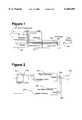
- FIG. 1is a drawing of a typical household cable system, the cable possibly being telephone, AC power, intercom, TV antenna or coax, alarm system, heater/air conditioning control, computer network, HiFi speaker wire, or any other general wire types;
- FIG. 2is a drawing of a stand-alone embodiment or implementation of a signal generator incorporating this invention
- FIG. 3is a drawing of an embedded hardware embodiment, with the signal generator and detector hardware inserted into a multimeter;
- FIG. 4is a drawing of an embedded software embodiment, with the invention contained completely within the control software of a TDR that already contains sufficient hardware to perform the functions of cable load detection and signal generation.
- FIG. 1illustrates a simple, typical household wiring or cable installation.
- Each roomis wired separately to a common connection box located in the back yard.
- the installercould place the signal generator 107 on wire 103 in the upstairs front bedroom and then travel down to the back yard connection box 105.
- the individualWith his or her receiver 106, the individual could probe each of the four wires at that connection box to try and determine which of the cables extends from the upstairs front bedroom.
- all four of the cablescause approximately the same tone indication (as would often be the case)
- he or shecould then sequentially short and open each pair of wires until the characteristics of the tone change. At that point, there would be positive identification of the wire pair.
- a versatile signal generator 201couples its output 202 to the cable connection 203 and to the input 204 of the open/short detector 205.
- the detector 205will set its output 206 to a logic 1 if it detects an open circuit at the cable connection 203, otherwise its output is logic 0.
- This detector output 206is coupled to the clock input of toggle flip flop 207 such that every time the detector output changes from a logic 0 to a logic 1 the output 208 of the flip flop will change its state.
- This output 208is coupled to the frequency control input 209 of the versatile signal generator 201.
- the output 208 of the flip flopis at some particular state, 1 or 0.
- Thiscauses the signal generator 201 to be generating a signal of the frequency that corresponds to that flip flop state of 0, for example 1000 Hz.
- the detector 205detects that short and changes its output 206 to a logic 0.
- the detector output 206When the user removes the short circuit from the connection pins 203, the detector output 206 will change to a logic 1. This change to a logic 1 will cause the toggle flip flop 207 to change its output state to a logic 1. Now the signal generator will be outputting a signal of the frequency that corresponds to the flip flop state of 1, 2000 Hz for example. If the user then re-applies and then removes the short circuit from the connection pins 203, the detector output 206 will change to 0 and then to 1. This will once again toggle the flip flop and the output 208 of the flip flop will now be 0. This will cause the signal generator 201 to output the signal of frequency 1000 Hz, corresponding to the state 1 of the flip flop. Note that this particular implementation only has two states for the characteristic frequency of the signal generator. However this invention encompasses a device that has any number of characteristic states more than two.
- this descriptionshows the toggle flip flop 207 changing its state when its clock changes from 0 to 1, reflecting the detection of the removal of a short on wires 203
- this inventionalso encompasses the situation where the flip flop 207 is of such a type that it changes its state when its clock changes from 1 to 0, reflecting the detection of a short on wires 203.
- FIG. 3shows a common multimeter with the addition of a versatile signal generator 310 to its analog circuit 304, and the addition of an open/short threshold detector 311 and toggle flip flop 312 to its control circuit 302.
- the mode switch 306is set by the user to the mode of operation desired, such as the measurement of Amps, Ohms or Volts.
- This mode switch 306is read by the control circuit 302 which then sends appropriate control signals to the analog circuit 304.
- This analog circuitthen performs the appropriate measurement of its environment via its test leads 305. The result of this measurement is sent back to the control circuit 302 where it is converted to the appropriate form for display on the readout 303.
- the mode switch 306would have an additional position which, when read by the control circuit 302 would enable the output of the ohm meter section 307 to be examined by the open/short threshold detector 311 and a sufficiently low reading from the ohm meter section 307 would set the output of the detector 311 and toggle the flip flop 312.
- the changed state of the flip flop 312is coupled to the signal generator 310 so as to change the specified characteristic of the signal generator 310.
- the analog circuit 304 and the control circuit 302are constructed with ASICs (Application Specific Integrated Circuit) and a small quantity of individual components. In some cases the two circuits are constructed within the same ASIC. It is a straightforward task for anyone skilled in the arts of multimeter design and ASIC design to include a versatile signal generator 310 in the analog circuit 304 and the open/short detector 311 and toggle flip flop 312 in the control circuit 302.
- ASICsApplication Specific Integrated Circuit
- FIG. 4shows an alternative embodiment wherein the invention is incorporated within a conventional TDR cable tester using only additional software and no additional hardware.
- the cost of adding this new capability to the TDRcould be virtually zero.
- the versatile signal generatoralready exists as the software controlled TDR pulse generator 409. The rate and pattern of repetition of the TDR pulse is already under the control of the control software 402.
- the detectoralso already exists as the TDR pulse receiver 407 and TDRs already have open/short threshold software 411 as part of their capability. All that would be needed is additional control software to monitor the state of the open/short threshold logic 411 and change the appropriate characteristic of the TDR pulse generator 409 when the open/short state changes from short to open.
- additional control softwarecan readily be devised by one skilled in the TDR art.
- the appropriate pulse generator changeable characteristiccould, for example, be the TDR pulse width, the pulse repetition rate, or the pulse repetition pattern.
Landscapes
- Physics & Mathematics (AREA)
- General Physics & Mathematics (AREA)
- Arrangements For Transmission Of Measured Signals (AREA)
- Testing Of Short-Circuits, Discontinuities, Leakage, Or Incorrect Line Connections (AREA)
Abstract
Description
Claims (11)
Priority Applications (3)
| Application Number | Priority Date | Filing Date | Title |
|---|---|---|---|
| US09/050,652US6160405A (en) | 1998-03-30 | 1998-03-30 | Method and apparatus for remotely changing signal characteristics of a signal generator |
| EP99200819AEP0947844A3 (en) | 1998-03-30 | 1999-03-17 | Method and apparatus for remotely changing signal characteristics of a signal generator |
| US09/652,424US6323654B1 (en) | 1998-03-30 | 2000-08-31 | Method and apparatus for remotely changing signal characteristics of a signal generator |
Applications Claiming Priority (1)
| Application Number | Priority Date | Filing Date | Title |
|---|---|---|---|
| US09/050,652US6160405A (en) | 1998-03-30 | 1998-03-30 | Method and apparatus for remotely changing signal characteristics of a signal generator |
Related Child Applications (1)
| Application Number | Title | Priority Date | Filing Date |
|---|---|---|---|
| US09/652,424DivisionUS6323654B1 (en) | 1998-03-30 | 2000-08-31 | Method and apparatus for remotely changing signal characteristics of a signal generator |
Publications (1)
| Publication Number | Publication Date |
|---|---|
| US6160405Atrue US6160405A (en) | 2000-12-12 |
Family
ID=21966545
Family Applications (2)
| Application Number | Title | Priority Date | Filing Date |
|---|---|---|---|
| US09/050,652Expired - LifetimeUS6160405A (en) | 1998-03-30 | 1998-03-30 | Method and apparatus for remotely changing signal characteristics of a signal generator |
| US09/652,424Expired - LifetimeUS6323654B1 (en) | 1998-03-30 | 2000-08-31 | Method and apparatus for remotely changing signal characteristics of a signal generator |
Family Applications After (1)
| Application Number | Title | Priority Date | Filing Date |
|---|---|---|---|
| US09/652,424Expired - LifetimeUS6323654B1 (en) | 1998-03-30 | 2000-08-31 | Method and apparatus for remotely changing signal characteristics of a signal generator |
Country Status (2)
| Country | Link |
|---|---|
| US (2) | US6160405A (en) |
| EP (1) | EP0947844A3 (en) |
Cited By (26)
| Publication number | Priority date | Publication date | Assignee | Title |
|---|---|---|---|---|
| US20030143945A1 (en)* | 1999-06-25 | 2003-07-31 | Chadwick George G. | Electromagnetic field communications system for wireless networks |
| US6653845B2 (en)* | 2002-02-25 | 2003-11-25 | Daimlerchrysler Corporation | Addressable open connector test circuit |
| US20040201534A1 (en)* | 2000-12-27 | 2004-10-14 | Yoshihiro Hagiwara | Method and apparatus for improving antenna efficiency |
| US20040201529A1 (en)* | 2000-12-27 | 2004-10-14 | Chadwick George G. | Antenna |
| US20050168392A1 (en)* | 2004-01-05 | 2005-08-04 | Cocomo Mb Communications, Inc. | Antenna efficiency |
| US20050195117A1 (en)* | 2000-08-10 | 2005-09-08 | Cocomo Mb Communications, Inc. | Antenna |
| US7030623B1 (en) | 2004-02-03 | 2006-04-18 | Kevin Carpenter | Electrical short tracing apparatus and method |
| US7091113B2 (en) | 2002-08-26 | 2006-08-15 | Micron Technology, Inc. | Methods of forming semiconductor constructions |
| US7716008B2 (en) | 2007-01-19 | 2010-05-11 | Nintendo Co., Ltd. | Acceleration data processing program, and storage medium, and acceleration data processing apparatus for use with the same |
| US7774155B2 (en) | 2006-03-10 | 2010-08-10 | Nintendo Co., Ltd. | Accelerometer-based controller |
| US7927216B2 (en) | 2005-09-15 | 2011-04-19 | Nintendo Co., Ltd. | Video game system with wireless modular handheld controller |
| US8089458B2 (en) | 2000-02-22 | 2012-01-03 | Creative Kingdoms, Llc | Toy devices and methods for providing an interactive play experience |
| US8157651B2 (en) | 2005-09-12 | 2012-04-17 | Nintendo Co., Ltd. | Information processing program |
| US8226493B2 (en) | 2002-08-01 | 2012-07-24 | Creative Kingdoms, Llc | Interactive play devices for water play attractions |
| US8267786B2 (en) | 2005-08-24 | 2012-09-18 | Nintendo Co., Ltd. | Game controller and game system |
| US8308563B2 (en) | 2005-08-30 | 2012-11-13 | Nintendo Co., Ltd. | Game system and storage medium having game program stored thereon |
| US8313379B2 (en) | 2005-08-22 | 2012-11-20 | Nintendo Co., Ltd. | Video game system with wireless modular handheld controller |
| US8409003B2 (en) | 2005-08-24 | 2013-04-02 | Nintendo Co., Ltd. | Game controller and game system |
| US8475275B2 (en) | 2000-02-22 | 2013-07-02 | Creative Kingdoms, Llc | Interactive toys and games connecting physical and virtual play environments |
| US8608535B2 (en) | 2002-04-05 | 2013-12-17 | Mq Gaming, Llc | Systems and methods for providing an interactive game |
| US8702515B2 (en) | 2002-04-05 | 2014-04-22 | Mq Gaming, Llc | Multi-platform gaming system using RFID-tagged toys |
| US8708821B2 (en) | 2000-02-22 | 2014-04-29 | Creative Kingdoms, Llc | Systems and methods for providing interactive game play |
| US8753165B2 (en) | 2000-10-20 | 2014-06-17 | Mq Gaming, Llc | Wireless toy systems and methods for interactive entertainment |
| US8758136B2 (en) | 1999-02-26 | 2014-06-24 | Mq Gaming, Llc | Multi-platform gaming systems and methods |
| US9011248B2 (en) | 2005-08-22 | 2015-04-21 | Nintendo Co., Ltd. | Game operating device |
| US9446319B2 (en) | 2003-03-25 | 2016-09-20 | Mq Gaming, Llc | Interactive gaming toy |
Families Citing this family (3)
| Publication number | Priority date | Publication date | Assignee | Title |
|---|---|---|---|---|
| US6922060B1 (en)* | 2002-07-23 | 2005-07-26 | Alstom Technology Ltd. | Method for detecting partial conductor short circuits, and device for performing and using the method |
| US6801043B2 (en)* | 2002-12-20 | 2004-10-05 | Intel Corporation | Time domain reflectometry based transmitter equalization |
| US9071912B1 (en) | 2013-02-08 | 2015-06-30 | Clear-Com Llc | Audio test tool |
Citations (10)
| Publication number | Priority date | Publication date | Assignee | Title |
|---|---|---|---|---|
| US4130794A (en)* | 1976-11-05 | 1978-12-19 | Cox C Eugene | Methods and means for identifying and testing circuit connections |
| US4510435A (en)* | 1981-09-02 | 1985-04-09 | Dainichi-Nippon Cables, Ltd. | Apparatus for electrically testing multi-core cables |
| US4524320A (en)* | 1983-06-17 | 1985-06-18 | Gary A. Harrelson | Conductor identifying probe and voltage supply device |
| US4563636A (en)* | 1983-12-12 | 1986-01-07 | Hewlett-Packard Company | Connection verification between circuit board and circuit tester |
| US4829284A (en)* | 1985-09-19 | 1989-05-09 | Seba-Dynatronic Messund Ortungstechnik Gmbh | Procedure for monitoring of an object using a signal line, together with a pulse measuring apparatus to carry out this procedure |
| US4862491A (en)* | 1987-04-14 | 1989-08-29 | Teletech Pty. Ltd. | Remote disconnection and short-circuiting apparatus and method |
| US5131028A (en)* | 1987-11-04 | 1992-07-14 | Chambers Charles W | Methods and apparatus for providing reciprocal impedance conversion |
| US5307398A (en)* | 1992-03-18 | 1994-04-26 | Joseph Contonzo | Remote controlled tone generator system |
| US5436554A (en)* | 1992-09-04 | 1995-07-25 | Decker, Jr.; Harold J. | Computer controlled cable tester |
| US5457441A (en)* | 1993-06-04 | 1995-10-10 | Progressive Electronics, Inc. | Inductive amplifier having two-terminal auto-on function |
Family Cites Families (7)
| Publication number | Priority date | Publication date | Assignee | Title |
|---|---|---|---|---|
| GB1352124A (en)* | 1970-07-08 | 1974-05-08 | Electricity Council | Cable fault location |
| GB2215065A (en)* | 1988-02-09 | 1989-09-13 | Edwyn Paul Dark | Tapping-out meter unit |
| US5122800A (en)* | 1989-01-26 | 1992-06-16 | Harald Philipp | Variable successive approximation converter |
| US5268644A (en)* | 1990-04-03 | 1993-12-07 | Ford Motor Company | Fault detection and isolation in automotive wiring harness by time-domain reflectometry |
| DE69124244T2 (en)* | 1991-11-12 | 1997-08-21 | Molex Inc | Wire presence and identification system |
| US5444695A (en)* | 1993-01-11 | 1995-08-22 | Forte Networks, Inc. | Token ring local area network testing apparatus providing station history information |
| US5376888A (en)* | 1993-06-09 | 1994-12-27 | Hook; William R. | Timing markers in time domain reflectometry systems |
- 1998
- 1998-03-30USUS09/050,652patent/US6160405A/ennot_activeExpired - Lifetime
- 1999
- 1999-03-17EPEP99200819Apatent/EP0947844A3/ennot_activeWithdrawn
- 2000
- 2000-08-31USUS09/652,424patent/US6323654B1/ennot_activeExpired - Lifetime
Patent Citations (10)
| Publication number | Priority date | Publication date | Assignee | Title |
|---|---|---|---|---|
| US4130794A (en)* | 1976-11-05 | 1978-12-19 | Cox C Eugene | Methods and means for identifying and testing circuit connections |
| US4510435A (en)* | 1981-09-02 | 1985-04-09 | Dainichi-Nippon Cables, Ltd. | Apparatus for electrically testing multi-core cables |
| US4524320A (en)* | 1983-06-17 | 1985-06-18 | Gary A. Harrelson | Conductor identifying probe and voltage supply device |
| US4563636A (en)* | 1983-12-12 | 1986-01-07 | Hewlett-Packard Company | Connection verification between circuit board and circuit tester |
| US4829284A (en)* | 1985-09-19 | 1989-05-09 | Seba-Dynatronic Messund Ortungstechnik Gmbh | Procedure for monitoring of an object using a signal line, together with a pulse measuring apparatus to carry out this procedure |
| US4862491A (en)* | 1987-04-14 | 1989-08-29 | Teletech Pty. Ltd. | Remote disconnection and short-circuiting apparatus and method |
| US5131028A (en)* | 1987-11-04 | 1992-07-14 | Chambers Charles W | Methods and apparatus for providing reciprocal impedance conversion |
| US5307398A (en)* | 1992-03-18 | 1994-04-26 | Joseph Contonzo | Remote controlled tone generator system |
| US5436554A (en)* | 1992-09-04 | 1995-07-25 | Decker, Jr.; Harold J. | Computer controlled cable tester |
| US5457441A (en)* | 1993-06-04 | 1995-10-10 | Progressive Electronics, Inc. | Inductive amplifier having two-terminal auto-on function |
Cited By (103)
| Publication number | Priority date | Publication date | Assignee | Title |
|---|---|---|---|---|
| US9468854B2 (en) | 1999-02-26 | 2016-10-18 | Mq Gaming, Llc | Multi-platform gaming systems and methods |
| US9186585B2 (en) | 1999-02-26 | 2015-11-17 | Mq Gaming, Llc | Multi-platform gaming systems and methods |
| US8888576B2 (en) | 1999-02-26 | 2014-11-18 | Mq Gaming, Llc | Multi-media interactive play system |
| US9731194B2 (en) | 1999-02-26 | 2017-08-15 | Mq Gaming, Llc | Multi-platform gaming systems and methods |
| US8758136B2 (en) | 1999-02-26 | 2014-06-24 | Mq Gaming, Llc | Multi-platform gaming systems and methods |
| US9861887B1 (en) | 1999-02-26 | 2018-01-09 | Mq Gaming, Llc | Multi-platform gaming systems and methods |
| US10300374B2 (en) | 1999-02-26 | 2019-05-28 | Mq Gaming, Llc | Multi-platform gaming systems and methods |
| US7099621B1 (en)* | 1999-06-25 | 2006-08-29 | Cocomo Mb Communications, Inc. | Electromagnetic field communications system for wireless networks |
| US20030143945A1 (en)* | 1999-06-25 | 2003-07-31 | Chadwick George G. | Electromagnetic field communications system for wireless networks |
| US6917785B2 (en)* | 1999-06-25 | 2005-07-12 | Cocomo Mb Communications, Inc. | Electromagnetic field communications system for wireless networks |
| US8491389B2 (en) | 2000-02-22 | 2013-07-23 | Creative Kingdoms, Llc. | Motion-sensitive input device and interactive gaming system |
| US9149717B2 (en) | 2000-02-22 | 2015-10-06 | Mq Gaming, Llc | Dual-range wireless interactive entertainment device |
| US8708821B2 (en) | 2000-02-22 | 2014-04-29 | Creative Kingdoms, Llc | Systems and methods for providing interactive game play |
| US9474962B2 (en) | 2000-02-22 | 2016-10-25 | Mq Gaming, Llc | Interactive entertainment system |
| US8686579B2 (en) | 2000-02-22 | 2014-04-01 | Creative Kingdoms, Llc | Dual-range wireless controller |
| US10307671B2 (en) | 2000-02-22 | 2019-06-04 | Mq Gaming, Llc | Interactive entertainment system |
| US8089458B2 (en) | 2000-02-22 | 2012-01-03 | Creative Kingdoms, Llc | Toy devices and methods for providing an interactive play experience |
| US8531050B2 (en) | 2000-02-22 | 2013-09-10 | Creative Kingdoms, Llc | Wirelessly powered gaming device |
| US8164567B1 (en) | 2000-02-22 | 2012-04-24 | Creative Kingdoms, Llc | Motion-sensitive game controller with optional display screen |
| US8169406B2 (en) | 2000-02-22 | 2012-05-01 | Creative Kingdoms, Llc | Motion-sensitive wand controller for a game |
| US8184097B1 (en) | 2000-02-22 | 2012-05-22 | Creative Kingdoms, Llc | Interactive gaming system and method using motion-sensitive input device |
| US8475275B2 (en) | 2000-02-22 | 2013-07-02 | Creative Kingdoms, Llc | Interactive toys and games connecting physical and virtual play environments |
| US9579568B2 (en) | 2000-02-22 | 2017-02-28 | Mq Gaming, Llc | Dual-range wireless interactive entertainment device |
| US9814973B2 (en) | 2000-02-22 | 2017-11-14 | Mq Gaming, Llc | Interactive entertainment system |
| US10188953B2 (en) | 2000-02-22 | 2019-01-29 | Mq Gaming, Llc | Dual-range wireless interactive entertainment device |
| US9713766B2 (en) | 2000-02-22 | 2017-07-25 | Mq Gaming, Llc | Dual-range wireless interactive entertainment device |
| US8368648B2 (en) | 2000-02-22 | 2013-02-05 | Creative Kingdoms, Llc | Portable interactive toy with radio frequency tracking device |
| US8915785B2 (en) | 2000-02-22 | 2014-12-23 | Creative Kingdoms, Llc | Interactive entertainment system |
| US8814688B2 (en) | 2000-02-22 | 2014-08-26 | Creative Kingdoms, Llc | Customizable toy for playing a wireless interactive game having both physical and virtual elements |
| US8790180B2 (en) | 2000-02-22 | 2014-07-29 | Creative Kingdoms, Llc | Interactive game and associated wireless toy |
| US20050195117A1 (en)* | 2000-08-10 | 2005-09-08 | Cocomo Mb Communications, Inc. | Antenna |
| US8961260B2 (en) | 2000-10-20 | 2015-02-24 | Mq Gaming, Llc | Toy incorporating RFID tracking device |
| US9931578B2 (en) | 2000-10-20 | 2018-04-03 | Mq Gaming, Llc | Toy incorporating RFID tag |
| US10307683B2 (en) | 2000-10-20 | 2019-06-04 | Mq Gaming, Llc | Toy incorporating RFID tag |
| US8753165B2 (en) | 2000-10-20 | 2014-06-17 | Mq Gaming, Llc | Wireless toy systems and methods for interactive entertainment |
| US9480929B2 (en) | 2000-10-20 | 2016-11-01 | Mq Gaming, Llc | Toy incorporating RFID tag |
| US9320976B2 (en) | 2000-10-20 | 2016-04-26 | Mq Gaming, Llc | Wireless toy systems and methods for interactive entertainment |
| US6956534B2 (en) | 2000-12-27 | 2005-10-18 | Cocomo Mb Communications, Inc. | Method and apparatus for improving antenna efficiency |
| US6891512B2 (en) | 2000-12-27 | 2005-05-10 | Cocomo Mb Cojmmunications, Inc. | Antenna |
| US20040201534A1 (en)* | 2000-12-27 | 2004-10-14 | Yoshihiro Hagiwara | Method and apparatus for improving antenna efficiency |
| US20040201529A1 (en)* | 2000-12-27 | 2004-10-14 | Chadwick George G. | Antenna |
| US9162148B2 (en) | 2001-02-22 | 2015-10-20 | Mq Gaming, Llc | Wireless entertainment device, system, and method |
| US8248367B1 (en) | 2001-02-22 | 2012-08-21 | Creative Kingdoms, Llc | Wireless gaming system combining both physical and virtual play elements |
| US8384668B2 (en) | 2001-02-22 | 2013-02-26 | Creative Kingdoms, Llc | Portable gaming device and gaming system combining both physical and virtual play elements |
| US9737797B2 (en) | 2001-02-22 | 2017-08-22 | Mq Gaming, Llc | Wireless entertainment device, system, and method |
| US9393491B2 (en) | 2001-02-22 | 2016-07-19 | Mq Gaming, Llc | Wireless entertainment device, system, and method |
| US10758818B2 (en) | 2001-02-22 | 2020-09-01 | Mq Gaming, Llc | Wireless entertainment device, system, and method |
| US8913011B2 (en) | 2001-02-22 | 2014-12-16 | Creative Kingdoms, Llc | Wireless entertainment device, system, and method |
| US10179283B2 (en) | 2001-02-22 | 2019-01-15 | Mq Gaming, Llc | Wireless entertainment device, system, and method |
| US8711094B2 (en) | 2001-02-22 | 2014-04-29 | Creative Kingdoms, Llc | Portable gaming device and gaming system combining both physical and virtual play elements |
| US6653845B2 (en)* | 2002-02-25 | 2003-11-25 | Daimlerchrysler Corporation | Addressable open connector test circuit |
| US20040070403A1 (en)* | 2002-02-25 | 2004-04-15 | Miesterfeld Frederick O. | Addressable open connector test circuit |
| US8608535B2 (en) | 2002-04-05 | 2013-12-17 | Mq Gaming, Llc | Systems and methods for providing an interactive game |
| US9616334B2 (en) | 2002-04-05 | 2017-04-11 | Mq Gaming, Llc | Multi-platform gaming system using RFID-tagged toys |
| US8702515B2 (en) | 2002-04-05 | 2014-04-22 | Mq Gaming, Llc | Multi-platform gaming system using RFID-tagged toys |
| US10010790B2 (en) | 2002-04-05 | 2018-07-03 | Mq Gaming, Llc | System and method for playing an interactive game |
| US10478719B2 (en) | 2002-04-05 | 2019-11-19 | Mq Gaming, Llc | Methods and systems for providing personalized interactive entertainment |
| US10507387B2 (en) | 2002-04-05 | 2019-12-17 | Mq Gaming, Llc | System and method for playing an interactive game |
| US9272206B2 (en) | 2002-04-05 | 2016-03-01 | Mq Gaming, Llc | System and method for playing an interactive game |
| US9463380B2 (en) | 2002-04-05 | 2016-10-11 | Mq Gaming, Llc | System and method for playing an interactive game |
| US11278796B2 (en) | 2002-04-05 | 2022-03-22 | Mq Gaming, Llc | Methods and systems for providing personalized interactive entertainment |
| US8827810B2 (en) | 2002-04-05 | 2014-09-09 | Mq Gaming, Llc | Methods for providing interactive entertainment |
| US8226493B2 (en) | 2002-08-01 | 2012-07-24 | Creative Kingdoms, Llc | Interactive play devices for water play attractions |
| US7091113B2 (en) | 2002-08-26 | 2006-08-15 | Micron Technology, Inc. | Methods of forming semiconductor constructions |
| US9707478B2 (en) | 2003-03-25 | 2017-07-18 | Mq Gaming, Llc | Motion-sensitive controller and associated gaming applications |
| US10369463B2 (en) | 2003-03-25 | 2019-08-06 | Mq Gaming, Llc | Wireless interactive game having both physical and virtual elements |
| US9393500B2 (en) | 2003-03-25 | 2016-07-19 | Mq Gaming, Llc | Wireless interactive game having both physical and virtual elements |
| US9993724B2 (en) | 2003-03-25 | 2018-06-12 | Mq Gaming, Llc | Interactive gaming toy |
| US11052309B2 (en) | 2003-03-25 | 2021-07-06 | Mq Gaming, Llc | Wireless interactive game having both physical and virtual elements |
| US8373659B2 (en) | 2003-03-25 | 2013-02-12 | Creative Kingdoms, Llc | Wirelessly-powered toy for gaming |
| US10583357B2 (en) | 2003-03-25 | 2020-03-10 | Mq Gaming, Llc | Interactive gaming toy |
| US9770652B2 (en) | 2003-03-25 | 2017-09-26 | Mq Gaming, Llc | Wireless interactive game having both physical and virtual elements |
| US9039533B2 (en) | 2003-03-25 | 2015-05-26 | Creative Kingdoms, Llc | Wireless interactive game having both physical and virtual elements |
| US8961312B2 (en) | 2003-03-25 | 2015-02-24 | Creative Kingdoms, Llc | Motion-sensitive controller and associated gaming applications |
| US9446319B2 (en) | 2003-03-25 | 2016-09-20 | Mq Gaming, Llc | Interactive gaming toy |
| US10022624B2 (en) | 2003-03-25 | 2018-07-17 | Mq Gaming, Llc | Wireless interactive game having both physical and virtual elements |
| US20050168392A1 (en)* | 2004-01-05 | 2005-08-04 | Cocomo Mb Communications, Inc. | Antenna efficiency |
| US7030623B1 (en) | 2004-02-03 | 2006-04-18 | Kevin Carpenter | Electrical short tracing apparatus and method |
| US9675878B2 (en) | 2004-09-29 | 2017-06-13 | Mq Gaming, Llc | System and method for playing a virtual game by sensing physical movements |
| US9700806B2 (en) | 2005-08-22 | 2017-07-11 | Nintendo Co., Ltd. | Game operating device |
| US10238978B2 (en) | 2005-08-22 | 2019-03-26 | Nintendo Co., Ltd. | Game operating device |
| US9498728B2 (en) | 2005-08-22 | 2016-11-22 | Nintendo Co., Ltd. | Game operating device |
| US10661183B2 (en) | 2005-08-22 | 2020-05-26 | Nintendo Co., Ltd. | Game operating device |
| US8313379B2 (en) | 2005-08-22 | 2012-11-20 | Nintendo Co., Ltd. | Video game system with wireless modular handheld controller |
| US10155170B2 (en) | 2005-08-22 | 2018-12-18 | Nintendo Co., Ltd. | Game operating device with holding portion detachably holding an electronic device |
| US9011248B2 (en) | 2005-08-22 | 2015-04-21 | Nintendo Co., Ltd. | Game operating device |
| US8409003B2 (en) | 2005-08-24 | 2013-04-02 | Nintendo Co., Ltd. | Game controller and game system |
| US10137365B2 (en) | 2005-08-24 | 2018-11-27 | Nintendo Co., Ltd. | Game controller and game system |
| US8834271B2 (en) | 2005-08-24 | 2014-09-16 | Nintendo Co., Ltd. | Game controller and game system |
| US8267786B2 (en) | 2005-08-24 | 2012-09-18 | Nintendo Co., Ltd. | Game controller and game system |
| US9227138B2 (en) | 2005-08-24 | 2016-01-05 | Nintendo Co., Ltd. | Game controller and game system |
| US8870655B2 (en) | 2005-08-24 | 2014-10-28 | Nintendo Co., Ltd. | Wireless game controllers |
| US11027190B2 (en) | 2005-08-24 | 2021-06-08 | Nintendo Co., Ltd. | Game controller and game system |
| US9044671B2 (en) | 2005-08-24 | 2015-06-02 | Nintendo Co., Ltd. | Game controller and game system |
| US9498709B2 (en) | 2005-08-24 | 2016-11-22 | Nintendo Co., Ltd. | Game controller and game system |
| US8308563B2 (en) | 2005-08-30 | 2012-11-13 | Nintendo Co., Ltd. | Game system and storage medium having game program stored thereon |
| US8708824B2 (en) | 2005-09-12 | 2014-04-29 | Nintendo Co., Ltd. | Information processing program |
| US8157651B2 (en) | 2005-09-12 | 2012-04-17 | Nintendo Co., Ltd. | Information processing program |
| US8430753B2 (en) | 2005-09-15 | 2013-04-30 | Nintendo Co., Ltd. | Video game system with wireless modular handheld controller |
| US7927216B2 (en) | 2005-09-15 | 2011-04-19 | Nintendo Co., Ltd. | Video game system with wireless modular handheld controller |
| USRE45905E1 (en) | 2005-09-15 | 2016-03-01 | Nintendo Co., Ltd. | Video game system with wireless modular handheld controller |
| US7774155B2 (en) | 2006-03-10 | 2010-08-10 | Nintendo Co., Ltd. | Accelerometer-based controller |
| US7716008B2 (en) | 2007-01-19 | 2010-05-11 | Nintendo Co., Ltd. | Acceleration data processing program, and storage medium, and acceleration data processing apparatus for use with the same |
Also Published As
| Publication number | Publication date |
|---|---|
| EP0947844A2 (en) | 1999-10-06 |
| US6323654B1 (en) | 2001-11-27 |
| EP0947844A3 (en) | 1999-12-08 |
Similar Documents
| Publication | Publication Date | Title |
|---|---|---|
| US6160405A (en) | Method and apparatus for remotely changing signal characteristics of a signal generator | |
| US5420512A (en) | Electronic cable testing system | |
| EP1387176B1 (en) | Time-domain reflectometer for testing terminated network cable | |
| EP1395840B1 (en) | Fault detection system and method | |
| US5268644A (en) | Fault detection and isolation in automotive wiring harness by time-domain reflectometry | |
| US4446421A (en) | Apparatus and method for locating faults in cables | |
| US20040085057A1 (en) | Voltage probe | |
| US20040046570A1 (en) | Aircraft multi-function wire and insulation tester | |
| US3944914A (en) | Fault detection method and apparatus for multiconductor cables | |
| US6859041B2 (en) | Methods for locating faults in aircraft branch conductors and determining the distance to the faults | |
| US4651084A (en) | Fault test apparatus for conductors of multiconductor cable | |
| US7598721B2 (en) | Locating a cable using synchronization portion and data portion of a tone packet of a system | |
| EP0503183B1 (en) | Instrument with continuity capture feature | |
| US4812752A (en) | Open finder | |
| JP5167568B2 (en) | Branch circuit connection check device for distribution board | |
| US7010096B1 (en) | Remote testing of a communications line | |
| US3037161A (en) | Method and apparatus for locating faults in transmission lines | |
| GB2444850A (en) | An apparatus for assisting measurement of the resistances of LV ring main circuits | |
| US6016058A (en) | In-service wiring verification circuitry | |
| RU2142142C1 (en) | Device locating point of fault in power transmission and communication lines | |
| GB2234598A (en) | Testing multiconductor cables | |
| JP3389446B2 (en) | Cable detector | |
| US12368797B2 (en) | Telephone line testing apparatus with remote control | |
| JPH0411180Y2 (en) | ||
| JPH0882648A (en) | Disconnection detecting device for connecting cable |
Legal Events
| Date | Code | Title | Description |
|---|---|---|---|
| AS | Assignment | Owner name:JOVIAL TEST EQUIPMENT, INC., CALIFORNIA Free format text:ASSIGNMENT OF ASSIGNORS INTEREST;ASSIGNORS:NEEDLE, DAVID L.;SHEPARD, STAN F.;GIN, GARY;REEL/FRAME:009078/0923 Effective date:19980323 | |
| STCF | Information on status: patent grant | Free format text:PATENTED CASE | |
| FEPP | Fee payment procedure | Free format text:PAT HOLDER NO LONGER CLAIMS SMALL ENTITY STATUS, ENTITY STATUS SET TO UNDISCOUNTED (ORIGINAL EVENT CODE: STOL); ENTITY STATUS OF PATENT OWNER: LARGE ENTITY | |
| REFU | Refund | Free format text:REFUND - SURCHARGE, PETITION TO ACCEPT PYMT AFTER EXP, UNINTENTIONAL (ORIGINAL EVENT CODE: R2551); ENTITY STATUS OF PATENT OWNER: LARGE ENTITY Free format text:REFUND - SURCHARGE FOR LATE PAYMENT, SMALL ENTITY (ORIGINAL EVENT CODE: R2554); ENTITY STATUS OF PATENT OWNER: LARGE ENTITY | |
| FPAY | Fee payment | Year of fee payment:4 | |
| SULP | Surcharge for late payment | ||
| AS | Assignment | Owner name:HARRIS CORPORATION, FLORIDA Free format text:ASSIGNMENT OF ASSIGNORS INTEREST;ASSIGNOR:JOVIAL TEST EQUIPMENT, INC.;REEL/FRAME:014863/0527 Effective date:20020131 | |
| AS | Assignment | Owner name:FLUKE CORPORATION, WASHINGTON Free format text:ASSIGNMENT OF ASSIGNORS INTEREST;ASSIGNOR:HARRIS CORPORATION;REEL/FRAME:016274/0166 Effective date:20050506 | |
| FPAY | Fee payment | Year of fee payment:8 | |
| FPAY | Fee payment | Year of fee payment:12 |