US6159316A - Method of making multi-pocket filter - Google Patents
Method of making multi-pocket filterDownload PDFInfo
- Publication number
- US6159316A US6159316AUS09/229,268US22926899AUS6159316AUS 6159316 AUS6159316 AUS 6159316AUS 22926899 AUS22926899 AUS 22926899AUS 6159316 AUS6159316 AUS 6159316A
- Authority
- US
- United States
- Prior art keywords
- webs
- strips
- filter element
- strip
- marginal portions
- Prior art date
- Legal status (The legal status is an assumption and is not a legal conclusion. Google has not performed a legal analysis and makes no representation as to the accuracy of the status listed.)
- Expired - Lifetime
Links
- 238000004519manufacturing processMethods0.000titleclaimsdescription6
- 238000000034methodMethods0.000claimsabstractdescription14
- 238000003466weldingMethods0.000claimsdescription20
- 239000000463materialSubstances0.000claimsdescription17
- 238000005520cutting processMethods0.000claimsdescription6
- 238000007789sealingMethods0.000claimsdescription6
- 229920002994synthetic fiberPolymers0.000claimsdescription4
- 230000002093peripheral effectEffects0.000claims1
- 238000003825pressingMethods0.000claims1
- 230000001105regulatory effectEffects0.000claims1
- 238000005192partitionMethods0.000abstractdescription22
- 239000007789gasSubstances0.000description12
- 239000002245particleSubstances0.000description8
- 239000000428dustSubstances0.000description7
- 239000004743PolypropyleneSubstances0.000description4
- 238000001914filtrationMethods0.000description4
- -1polypropylenePolymers0.000description4
- 229920001155polypropylenePolymers0.000description4
- 238000011144upstream manufacturingMethods0.000description4
- 239000002184metalSubstances0.000description3
- 238000011437continuous methodMethods0.000description2
- 238000010586diagramMethods0.000description2
- 239000002657fibrous materialSubstances0.000description2
- 230000004927fusionEffects0.000description2
- 239000002243precursorSubstances0.000description2
- 239000004831Hot glueSubstances0.000description1
- 238000004378air conditioningMethods0.000description1
- 239000004599antimicrobialSubstances0.000description1
- 238000005265energy consumptionMethods0.000description1
- 238000011156evaluationMethods0.000description1
- 239000012943hotmeltSubstances0.000description1
- 238000011835investigationMethods0.000description1
- 238000012423maintenanceMethods0.000description1
- 230000000813microbial effectEffects0.000description1
- 239000000203mixtureSubstances0.000description1
- 239000005445natural materialSubstances0.000description1
- 239000004033plasticSubstances0.000description1
- 229920003023plasticPolymers0.000description1
- 239000000565sealantSubstances0.000description1
Images


Classifications
- B—PERFORMING OPERATIONS; TRANSPORTING
- B01—PHYSICAL OR CHEMICAL PROCESSES OR APPARATUS IN GENERAL
- B01D—SEPARATION
- B01D46/00—Filters or filtering processes specially modified for separating dispersed particles from gases or vapours
- B01D46/02—Particle separators, e.g. dust precipitators, having hollow filters made of flexible material
- B01D46/023—Pockets filters, i.e. multiple bag filters mounted on a common frame
- B—PERFORMING OPERATIONS; TRANSPORTING
- B01—PHYSICAL OR CHEMICAL PROCESSES OR APPARATUS IN GENERAL
- B01D—SEPARATION
- B01D46/00—Filters or filtering processes specially modified for separating dispersed particles from gases or vapours
- B01D46/0001—Making filtering elements
- B—PERFORMING OPERATIONS; TRANSPORTING
- B01—PHYSICAL OR CHEMICAL PROCESSES OR APPARATUS IN GENERAL
- B01D—SEPARATION
- B01D46/00—Filters or filtering processes specially modified for separating dispersed particles from gases or vapours
- B01D46/02—Particle separators, e.g. dust precipitators, having hollow filters made of flexible material
- B—PERFORMING OPERATIONS; TRANSPORTING
- B01—PHYSICAL OR CHEMICAL PROCESSES OR APPARATUS IN GENERAL
- B01D—SEPARATION
- B01D2265/00—Casings, housings or mounting for filters specially adapted for separating dispersed particles from gases or vapours
- B01D2265/04—Permanent measures for connecting different parts of the filter, e.g. welding, glueing or moulding
- B—PERFORMING OPERATIONS; TRANSPORTING
- B01—PHYSICAL OR CHEMICAL PROCESSES OR APPARATUS IN GENERAL
- B01D—SEPARATION
- B01D2265/00—Casings, housings or mounting for filters specially adapted for separating dispersed particles from gases or vapours
- B01D2265/06—Details of supporting structures for filtering material, e.g. cores
- Y—GENERAL TAGGING OF NEW TECHNOLOGICAL DEVELOPMENTS; GENERAL TAGGING OF CROSS-SECTIONAL TECHNOLOGIES SPANNING OVER SEVERAL SECTIONS OF THE IPC; TECHNICAL SUBJECTS COVERED BY FORMER USPC CROSS-REFERENCE ART COLLECTIONS [XRACs] AND DIGESTS
- Y10—TECHNICAL SUBJECTS COVERED BY FORMER USPC
- Y10S—TECHNICAL SUBJECTS COVERED BY FORMER USPC CROSS-REFERENCE ART COLLECTIONS [XRACs] AND DIGESTS
- Y10S55/00—Gas separation
- Y10S55/12—Pocket type filter
- Y—GENERAL TAGGING OF NEW TECHNOLOGICAL DEVELOPMENTS; GENERAL TAGGING OF CROSS-SECTIONAL TECHNOLOGIES SPANNING OVER SEVERAL SECTIONS OF THE IPC; TECHNICAL SUBJECTS COVERED BY FORMER USPC CROSS-REFERENCE ART COLLECTIONS [XRACs] AND DIGESTS
- Y10—TECHNICAL SUBJECTS COVERED BY FORMER USPC
- Y10T—TECHNICAL SUBJECTS COVERED BY FORMER US CLASSIFICATION
- Y10T156/00—Adhesive bonding and miscellaneous chemical manufacture
- Y10T156/10—Methods of surface bonding and/or assembly therefor
- Y10T156/1002—Methods of surface bonding and/or assembly therefor with permanent bending or reshaping or surface deformation of self sustaining lamina
- Y10T156/1007—Running or continuous length work
- Y10T156/1008—Longitudinal bending
- Y10T156/101—Prior to or during assembly with additional lamina
- Y—GENERAL TAGGING OF NEW TECHNOLOGICAL DEVELOPMENTS; GENERAL TAGGING OF CROSS-SECTIONAL TECHNOLOGIES SPANNING OVER SEVERAL SECTIONS OF THE IPC; TECHNICAL SUBJECTS COVERED BY FORMER USPC CROSS-REFERENCE ART COLLECTIONS [XRACs] AND DIGESTS
- Y10—TECHNICAL SUBJECTS COVERED BY FORMER USPC
- Y10T—TECHNICAL SUBJECTS COVERED BY FORMER US CLASSIFICATION
- Y10T156/00—Adhesive bonding and miscellaneous chemical manufacture
- Y10T156/10—Methods of surface bonding and/or assembly therefor
- Y10T156/1052—Methods of surface bonding and/or assembly therefor with cutting, punching, tearing or severing
- Y10T156/108—Flash, trim or excess removal
- Y—GENERAL TAGGING OF NEW TECHNOLOGICAL DEVELOPMENTS; GENERAL TAGGING OF CROSS-SECTIONAL TECHNOLOGIES SPANNING OVER SEVERAL SECTIONS OF THE IPC; TECHNICAL SUBJECTS COVERED BY FORMER USPC CROSS-REFERENCE ART COLLECTIONS [XRACs] AND DIGESTS
- Y10—TECHNICAL SUBJECTS COVERED BY FORMER USPC
- Y10T—TECHNICAL SUBJECTS COVERED BY FORMER US CLASSIFICATION
- Y10T156/00—Adhesive bonding and miscellaneous chemical manufacture
- Y10T156/10—Methods of surface bonding and/or assembly therefor
- Y10T156/1052—Methods of surface bonding and/or assembly therefor with cutting, punching, tearing or severing
- Y10T156/1084—Methods of surface bonding and/or assembly therefor with cutting, punching, tearing or severing of continuous or running length bonded web
Definitions
- the inventionrelates to the filtration of gases, typically of air to remove dust particles.
- the particlesmay range from about 0.3 to about 30 micron in size.
- a gas filter bagfrom gas permeable natural material in the form of generally parallel pockets.
- the pocketshave an open upstream inlet and a closed bottom end, the intention being that the dust particles will be trapped in the closed end of the pockets as the gas flow passes therethrough.
- the pocketsmay be defined by longitudinal seams formed by stitching.
- a hot melt adhesiveis applied over the stitched holes to seal them to avoid escape of particles. This is a labour intensive manufacturing method and the gas entrapment properties are not very good. It is one object of the invention to provide a gas filter of improved performance.
- a gas filter elementcomprising
- two side wallsforms of gas permeable material joined along three of their sides to define a pocket having an upstream open inlet and a downstream closed end, characterised in that generally parallel partitions bridge the opposite side walls to define individual pocket portions extending from the inlet end to the closed end, marginal portions of the partitions being secured to the inside of the side walls, whereby in use the air filter element exhibits a low pressure drop and a high degree of dust efficiency and dust holding capacity.
- the wallsmay be made of any suitable material which may be wholly or mainly synthetic fibres. Because the partitions are joined to the walls by a welding process, the material should be fusible (or at least thereof should be).
- the partitionis a thin generally planar strip of fusible material which in use presents a narrow edge to the flow of air.
- the marginal portionsare secured to the inner surface of the side walls by ultrasonic welding.
- a short length portion of one edge of the partition adjacent the open inlet endis not joined to the inner surface of the adjacent wall to permit flexure of the front end of the pocket so that it may easily be mounted in say a filter header frame.
- an elongate slitis formed in the upstream end portion of the partition to provide two flaps which enable the pocket to be opened in the manner of a jaw to engage the frame. The length and shape of the slit will be determined according to each filter element and frame, which typically is a header frame.
- the inventionprovides a continuous method of making a succession of pockets for a gas filter element, the method comprising:
- FIG. 1is a plan view of one filter bag of the invention
- FIG. 2is a side elevation of the filter bag of FIG. 1;
- FIG. 3is a partial front elevation of the pocket of the filter bag of FIG. 1 drawn to a much enlarged scale
- FIG. 4is a much enlarged view of one partition circled at A in FIG. 3;
- FIG. 5shows a flow diagram for one continuous method of manufacture of a pocket of the filter bag.
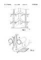
- FIG. 6is a partial front elevation of another filter bag of the invention.
- FIG. 7is a view of one partition circled at B in FIG. 6;
- FIG. 8is a perspective view showing part of the mouth of the bag in the open condition
- FIG. 9is a section through a frame having pockets showing two pocket partitions
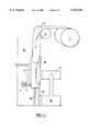
- FIG. 10shows a flow diagram for a method of continuous manufacture of a pocket of the filter bag of FIGS. 6 to 9;
- FIG. 11shows in detail the fold up former and an ultrasonic welding unit used in the method of FIG. 10.
- the filter bag shown in FIGS. 1 to 4comprises two layers L1,L2 of gas permeable of synthetic fibrous material secured together to provide a bag having elongate filter elements, i.e. cells or pockets P which are shown in FIG. 2.
- the side wallsmay be formed of any suitable synthetic fibre material or blend of materials.
- One exampleis polypropylene.
- the materialmay be treated, e.g. with an antimicrobial agent to resist microbial mould growth and build up of moulds or mildews.
- the two layersare sealed together along three sides by double seals S1, as a result of which the pockets are closed at their bottom or distal ends Pb but open at their mouths Pm.
- the bagis generally rectangular as seen in plan.
- the pocketshave a generally rectangular open inlet or mouth Pm, (except for the end ones Pe where they tend to be more triangular because of the way the two layers L1,L2 are joined together).
- individual pocketscontain partitions 5 to form pocket portions.
- the partitions 5are made of webs of fusible natural or synthetic sheet material such as polypropylene.
- the marginal portions 5a,5bare sealed to the inside surface of the layers L1,L2 respectively.
- the partitions 5extend the full distance from the front to the rear of the bag so that as shown in FIG. 1 there are parallel elongate seams S2.
- the bagis made in the following general way and as shown in FIG. 5.
- the apparatuscomprises two rolls of webs W1,W2 which are located one on each side of two ultrasonic welding units U each made up of a shoe 6 and a horn unit 7 and are fed to extend parallel to each other one on each side of the units U.
- Strips or ribbons R of polypropyleneare fed between the webs to the units U and when the assembly is fed passed the ultrasonic welding unit fusion takes place to form the partitions 5.
- one unit Uis arranged to make a continuous join the other has an interruption to provide a short length portion of one edge of the partition to be formed adjacent the intended open inlet so that the formed pocket P can flex at its front end for mounting in a filter header frame.
- the sides of the bag precursorare sealed by other ultrasonic welding units U.
- the formed bagis fed passed a cutting unit C to cut an individual bag, the rear end of which is then sealed, preferably heat sealed. This process is continuous, and the parameters may easily be adjusted according to the nature of the webs, fusion temperature and time, and dimensions.
- a filter bag of the inventionwas tested in the filtration of dust laden air.
- the bagwas mounted in a frame. It was easy to inflate. There was a high level of dust collection and a very low overall pressure drop.
- the filter resistancewas controlled.
- the partitions 5hold the pockets P in controlled aerodynamic configuration to ensure a uniform shape independent of the air flow.
- the ultrasonic bondingensures a strong connection without holes. This eliminates leakage or bypass of the particles through such holes. It also avoids the need to seal needlepunched holes using a hot melt sealant, giving more useful filtration area.
- the inlet end of the partition 5is slit to form two general parallel side flaps F1,F2 sides separated by a gap.
- the slitextends a short distance in from the end, sufficient to give the necessary flexibility according to the strength of the materials forming the layers L1,L2 and the partition 5.
- the flapsare secured to the layers by the double seals 6A,6B which are ultrasonic seals. As a result, the mouth of the pocket can be open in the manner of jaws, and the engagement of the partition and the walls will not be broken.
- the bagis connected to a metal header or frame 10 of generally rectangular section.
- the front portions of adjacent pocketsare crimped or otherwise secured by metal clamps to the edge of the frame.
- the header or holding framemay be of any suitable type, e.g. for front, rear or side withdrawal mounting.
- the framemay be made of metal or plastics.
- the bagcan be made on a continuous basis in the following way shown in FIGS. 10 and 11.
- the apparatuscomprises parallel rod-shaped ultrasonic welding units U1, U2 and U3 each made up of a shoe and horn or anvil unit and two rolls of synthetic fibrous material W1,W2 which are located on opposite side of U1 and U2 and are fed to extend parallel to each other on opposite sides of U1 and U2 (see FIG. 10).
- Strips or ribbons R of polypropyleneare fed between the webs W1, W2 and the units U1 and U2 to fuse both marginal edges of R to the web.
- the sides of the precursorare sealed by other ultrasonic welding units U3.
- the partly formed bagis fed passed a cutting unit C to cut an individual bag, the rear end of which is then sealed, preferably heat sealed.
- a marginal 5a,5b portion of each partition 5 near the upstream end of the elementis then cut to introduce the longitudinal slit and form the flaps F1,F2.
- each strip Ris wound off a reel 11 over a roller 12 and fed into a former 20 the top edge of which is curved to upturn the two margins 5a,5b so that the strip is generally channel shaped.
- the folded up stripis then passed through the unit at the lower end of which is an ultrasonic shoe 6 in the form of a wheel having a patterned surface.
- the wheel 6is on a shaft which is rotated by means of a belt drive 21. Behind the wheel is a web W1,W2 and behind that is the horn 7 of the ultrasonic welding unit in line with the wheel. As the margin 5a of the strip and the web W1 meet the shoe 6 and the horn 7 ultrasonic energy is applied to fuse them together.
- the webcomprises an inner skin and an outer carrier surface with filter media in between; the margin 5a is fused to the inner skin).
- Pressureis applied by the arm 31 of a rocker 30 under pneumatic control to urge the margin 5a onto the web so that there is good contact in between.
- the weldingmust be sufficient to secure the margin 5a and the web W1 together but not so strong that either material will be torn in use or be burned by the welding.
- the margin 5bwill be welded to its web W2 using another unit further down the line.
- the side seals S1are made a short distance in from the longitudinal edge from the webs and a slitter, not shown, is used to cut away the excess material which is then disposed of.
- the inventionalso includes a method of filtration, comprising passing gas under pressure through a filter element as defined and causing or allowing the particles to collect in the filter pockets.
- the inventionalso includes apparatus for making the filter elements.
- the inventionis useful wherever bag filters are suitable.
- the inventionensures that heavyweights of dust are trapped in the filter elements over extended maintenance periods; can protect equipment in general air conditioning plant, e.g. in hospitals, communal buildings, office suites, retail outlets and the like; and reduces energy consumption because of the low initial resistance to air flow.
Landscapes
- Chemical & Material Sciences (AREA)
- Chemical Kinetics & Catalysis (AREA)
- Filtering Of Dispersed Particles In Gases (AREA)
- Filtering Materials (AREA)
Abstract
Description
Claims (7)
Priority Applications (1)
| Application Number | Priority Date | Filing Date | Title |
|---|---|---|---|
| US09/703,048US6258142B1 (en) | 1998-01-16 | 2000-10-31 | Multi-pocket filter |
Applications Claiming Priority (4)
| Application Number | Priority Date | Filing Date | Title |
|---|---|---|---|
| GB9801012 | 1998-01-16 | ||
| GB9801012AGB2329854B (en) | 1998-01-16 | 1998-01-16 | Gas filtration |
| GBGB9824538.4AGB9824538D0 (en) | 1998-01-16 | 1998-11-09 | Gas filtration |
| GB9824538 | 1998-11-09 |
Related Child Applications (1)
| Application Number | Title | Priority Date | Filing Date |
|---|---|---|---|
| US09/703,048DivisionUS6258142B1 (en) | 1998-01-16 | 2000-10-31 | Multi-pocket filter |
Publications (1)
| Publication Number | Publication Date |
|---|---|
| US6159316Atrue US6159316A (en) | 2000-12-12 |
Family
ID=26312971
Family Applications (2)
| Application Number | Title | Priority Date | Filing Date |
|---|---|---|---|
| US09/229,268Expired - LifetimeUS6159316A (en) | 1998-01-16 | 1999-01-13 | Method of making multi-pocket filter |
| US09/703,048Expired - LifetimeUS6258142B1 (en) | 1998-01-16 | 2000-10-31 | Multi-pocket filter |
Family Applications After (1)
| Application Number | Title | Priority Date | Filing Date |
|---|---|---|---|
| US09/703,048Expired - LifetimeUS6258142B1 (en) | 1998-01-16 | 2000-10-31 | Multi-pocket filter |
Country Status (4)
| Country | Link |
|---|---|
| US (2) | US6159316A (en) |
| EP (1) | EP1047487A1 (en) |
| AU (1) | AU2173599A (en) |
| WO (1) | WO1999036154A1 (en) |
Cited By (3)
| Publication number | Priority date | Publication date | Assignee | Title |
|---|---|---|---|---|
| US6267832B1 (en)* | 1999-08-11 | 2001-07-31 | Aaf International | Method and apparatus for automated manufacture of unit filters |
| US20090049811A1 (en)* | 2007-08-23 | 2009-02-26 | Kyung-Ju Choi | Pocket Filter Joiner Arrangement and Method of Making |
| WO2016130661A1 (en)* | 2015-02-10 | 2016-08-18 | Walk Industrial Inc. | Filtration assembly and system |
Families Citing this family (8)
| Publication number | Priority date | Publication date | Assignee | Title |
|---|---|---|---|---|
| DE29800969U1 (en)* | 1998-01-22 | 1998-04-16 | Kluge Klaus Dipl Ing | Spacer system for pocket filters |
| DE10053226A1 (en)* | 2000-10-26 | 2002-07-11 | Tesa Ag | Use of a spacer textile as pollen protection for windows and doors |
| US6830639B2 (en)* | 2001-05-14 | 2004-12-14 | Pittsfield Weaving Co., Inc. | Method and apparatus for producing folded labels having rounded corners |
| US6844047B2 (en)* | 2002-10-07 | 2005-01-18 | Eastman Kodak Company | Optical element containing nanocomposite materials |
| US7186287B2 (en)* | 2004-02-17 | 2007-03-06 | Beier Scott B | Disposable filter for a fluid handling device and a method for using the same |
| US20090049810A1 (en)* | 2007-08-23 | 2009-02-26 | Green Thomas B | Dust filtration bag and frame apparatus and method |
| US8690980B2 (en) | 2010-08-31 | 2014-04-08 | Bha Altair, Llc | Filter pocket arrangement with increased filter media area |
| CA2993351C (en)* | 2015-08-03 | 2023-04-25 | Parker-Hannifin Corporation | Filter with preferential air flow |
Citations (13)
| Publication number | Priority date | Publication date | Assignee | Title |
|---|---|---|---|---|
| US2213602A (en)* | 1939-01-13 | 1940-09-03 | Pneumatic Scale Corp | Method of making a package |
| US2224753A (en)* | 1938-09-16 | 1940-12-10 | Pneumatic Scale Corp | Tea or coffee bag and method of making the same |
| US2350930A (en)* | 1942-01-01 | 1944-06-06 | Ivers Lee Co | Machine for making and filling packages |
| US3319539A (en)* | 1965-01-25 | 1967-05-16 | Bartelt Engineering Co Inc | Machine for making double-wall packages |
| US3468731A (en)* | 1966-07-01 | 1969-09-23 | Branson Instr | Method and apparatus for sonically sealing the end portion of thermoplastic tubular containers |
| US3599388A (en)* | 1968-12-13 | 1971-08-17 | Norman Feingold | Method of and apparatus for forming and loading containers |
| US4164400A (en)* | 1976-12-21 | 1979-08-14 | Scott/Chatham Company | Filters |
| US4356011A (en)* | 1981-05-26 | 1982-10-26 | Allis-Chalmers Corporation | Pocket filter assembly |
| US4512136A (en)* | 1982-08-23 | 1985-04-23 | Trinity Associates, A Partnership Of The State Of Pennsylvania | Fitment attachment methods in horizontal form/fill/seal machines |
| US4539793A (en)* | 1983-04-25 | 1985-09-10 | S. C. Johnson & Son, Inc. | Method of forming a burstable pouch |
| US5181365A (en)* | 1991-12-09 | 1993-01-26 | Minnesota Mining And Manufacturing Company | Method and apparatus for forming individual pouches from a continuous web and packaging a product in the individual pouches |
| US5215609A (en)* | 1991-12-20 | 1993-06-01 | Sanders Scott L | Continuous process for producing ultrasonically welded air filters |
| US5846360A (en)* | 1997-01-09 | 1998-12-08 | Gil; George | Filter and method and apparatus for manufacture thereof |
Family Cites Families (4)
| Publication number | Priority date | Publication date | Assignee | Title |
|---|---|---|---|---|
| DE7529340U (en)* | 1975-09-17 | 1976-02-19 | Freudenberg Carl Fa , 6940 Weinheim | GAS FILTER ELEMENT |
| FR2524816A2 (en)* | 1981-12-29 | 1983-10-14 | Dollfus Noack | Filter elements, esp. filter bags - made using two porous sheets joined together by reinforcing threads made of polymer and bonded to sheets by heat and pressure |
| US5928396A (en)* | 1997-12-31 | 1999-07-27 | Aaf International | Pocket filter and method and apparatus for making the same |
| US6010548A (en)* | 1998-01-30 | 2000-01-04 | Freudenberg Nonwovens Limited Partnership | Spaced pocket filter assembly and method of manufacturing same |
- 1999
- 1999-01-13USUS09/229,268patent/US6159316A/ennot_activeExpired - Lifetime
- 1999-01-15WOPCT/GB1999/000148patent/WO1999036154A1/ennot_activeApplication Discontinuation
- 1999-01-15EPEP99901729Apatent/EP1047487A1/ennot_activeCeased
- 1999-01-15AUAU21735/99Apatent/AU2173599A/ennot_activeAbandoned
- 2000
- 2000-10-31USUS09/703,048patent/US6258142B1/ennot_activeExpired - Lifetime
Patent Citations (15)
| Publication number | Priority date | Publication date | Assignee | Title |
|---|---|---|---|---|
| US2224753A (en)* | 1938-09-16 | 1940-12-10 | Pneumatic Scale Corp | Tea or coffee bag and method of making the same |
| US2213602A (en)* | 1939-01-13 | 1940-09-03 | Pneumatic Scale Corp | Method of making a package |
| US2350930A (en)* | 1942-01-01 | 1944-06-06 | Ivers Lee Co | Machine for making and filling packages |
| US3319539A (en)* | 1965-01-25 | 1967-05-16 | Bartelt Engineering Co Inc | Machine for making double-wall packages |
| US3468731A (en)* | 1966-07-01 | 1969-09-23 | Branson Instr | Method and apparatus for sonically sealing the end portion of thermoplastic tubular containers |
| US3599388A (en)* | 1968-12-13 | 1971-08-17 | Norman Feingold | Method of and apparatus for forming and loading containers |
| US4164400A (en)* | 1976-12-21 | 1979-08-14 | Scott/Chatham Company | Filters |
| US4356011A (en)* | 1981-05-26 | 1982-10-26 | Allis-Chalmers Corporation | Pocket filter assembly |
| US4512136A (en)* | 1982-08-23 | 1985-04-23 | Trinity Associates, A Partnership Of The State Of Pennsylvania | Fitment attachment methods in horizontal form/fill/seal machines |
| US4539793A (en)* | 1983-04-25 | 1985-09-10 | S. C. Johnson & Son, Inc. | Method of forming a burstable pouch |
| US5181365A (en)* | 1991-12-09 | 1993-01-26 | Minnesota Mining And Manufacturing Company | Method and apparatus for forming individual pouches from a continuous web and packaging a product in the individual pouches |
| US5215609A (en)* | 1991-12-20 | 1993-06-01 | Sanders Scott L | Continuous process for producing ultrasonically welded air filters |
| US5846360A (en)* | 1997-01-09 | 1998-12-08 | Gil; George | Filter and method and apparatus for manufacture thereof |
| US5885409A (en)* | 1997-01-09 | 1999-03-23 | Gil; George | Filter and method and apparatus for manufacture thereof |
| US5891208A (en)* | 1997-01-09 | 1999-04-06 | Gil; George | Multilayer filter |
Cited By (6)
| Publication number | Priority date | Publication date | Assignee | Title |
|---|---|---|---|---|
| US6267832B1 (en)* | 1999-08-11 | 2001-07-31 | Aaf International | Method and apparatus for automated manufacture of unit filters |
| US20090049811A1 (en)* | 2007-08-23 | 2009-02-26 | Kyung-Ju Choi | Pocket Filter Joiner Arrangement and Method of Making |
| WO2016130661A1 (en)* | 2015-02-10 | 2016-08-18 | Walk Industrial Inc. | Filtration assembly and system |
| US9968878B2 (en) | 2015-02-10 | 2018-05-15 | Walk Industrial, Inc. | Filtration assembly and system |
| US10758857B2 (en) | 2015-02-10 | 2020-09-01 | Walk Industrial, Inc. | Filtration assembly and system |
| US11291941B2 (en) | 2015-02-10 | 2022-04-05 | Walk Industrial, Inc. | Filtration assembly and system |
Also Published As
| Publication number | Publication date |
|---|---|
| EP1047487A1 (en) | 2000-11-02 |
| AU2173599A (en) | 1999-08-02 |
| US6258142B1 (en) | 2001-07-10 |
| WO1999036154A1 (en) | 1999-07-22 |
Similar Documents
| Publication | Publication Date | Title |
|---|---|---|
| US6159316A (en) | Method of making multi-pocket filter | |
| US6521011B1 (en) | Self-supporting pleated filter and method of making same | |
| US6010548A (en) | Spaced pocket filter assembly and method of manufacturing same | |
| CA2034867A1 (en) | Filter insert formed as a pleated pack and a process for its production | |
| US4930905A (en) | Thermoplastic bag with integral draw strip and method of manufacture | |
| US5928396A (en) | Pocket filter and method and apparatus for making the same | |
| CZ287578B6 (en) | Filter element | |
| US20050204714A1 (en) | Self-supporting pleated filter and method of making same | |
| US12053733B2 (en) | Pleated air filter with reinforcing filaments comprising locally-thinned bending zones | |
| WO2008048640A2 (en) | Method of making bag with interrupted side gussets | |
| US10207214B2 (en) | Filter with bidirectional pleated media | |
| GB2333249A (en) | Ultrasonically welded air filter element | |
| US10335729B1 (en) | Structural support for air filter | |
| US20090049811A1 (en) | Pocket Filter Joiner Arrangement and Method of Making | |
| EP0297075B1 (en) | Filter bag for a filter section | |
| WO2020081324A1 (en) | Pleated channel flow filter and/or roll form method | |
| GB2329854A (en) | Gas filter element | |
| JPH08215527A (en) | Filter unit manufacturing method | |
| EP0108798A1 (en) | Method and apparatus for continuous formation of reclosable article wrappers | |
| JPH0889737A (en) | filter | |
| EP0951932B1 (en) | Filter and method for the fabrication thereof | |
| JPS5839892Y2 (en) | bag making machine | |
| JPH09173751A (en) | Filter member, filter, and method of manufacturing filter | |
| CN107635642A (en) | V-type filter and preparation method thereof | |
| JP2000233458A (en) | Method for manufacturing triangular packaging bag, and device therefor |
Legal Events
| Date | Code | Title | Description |
|---|---|---|---|
| AS | Assignment | Owner name:MCLEOD RUSSEL HOLDINGS PLC, GREAT BRITAIN Free format text:ASSIGNMENT OF ASSIGNORS INTEREST;ASSIGNORS:HOLT, CLIVE JOHN;RIDGEWAY, CHARLES W.;REEL/FRAME:009985/0105;SIGNING DATES FROM 19990517 TO 19990521 | |
| AS | Assignment | Owner name:FILTRATION GROUP INCORPORATED, ILLINOIS Free format text:ASSIGNMENT OF ASSIGNORS INTEREST;ASSIGNOR:MCLEOD RUSSEL HOLDINGS, PLC;REEL/FRAME:011131/0455 Effective date:19990930 | |
| STCF | Information on status: patent grant | Free format text:PATENTED CASE | |
| FPAY | Fee payment | Year of fee payment:4 | |
| FPAY | Fee payment | Year of fee payment:8 | |
| AS | Assignment | Owner name:COLE TAYLOR BANK, ILLINOIS Free format text:SECURITY AGREEMENT;ASSIGNORS:FILTRATION GROUP, INCORPORATED;FILTRATION GROUP HOLDINGS, LLC;FILTRAIR, INC.;AND OTHERS;REEL/FRAME:022610/0930 Effective date:20090325 | |
| FPAY | Fee payment | Year of fee payment:12 | |
| AS | Assignment | Owner name:FILTRATION GROUP LLC (F/K/A FILTRATION GROUP INCOR Free format text:RELEASE BY SECURED PARTY;ASSIGNOR:COLE TAYLOR BANK;REEL/FRAME:029235/0004 Effective date:20121031 Owner name:FILTRAN LLC, ILLINOIS Free format text:RELEASE BY SECURED PARTY;ASSIGNOR:COLE TAYLOR BANK;REEL/FRAME:029235/0004 Effective date:20121031 Owner name:BANK OF MONTREAL, AS ADMINISTRATIVE AGENT, ILLINOI Free format text:SECURITY AGREEMENT;ASSIGNORS:CHEMCO MANUFACTURING CO., INC.;FILTRAN LLC;FILTRATION GROUP LLC;REEL/FRAME:029232/0325 Effective date:20121031 | |
| AS | Assignment | Owner name:GOLDMAN SACHS BANK USA, AS COLLATERAL AGENT, NEW JERSEY Free format text:SECURITY INTEREST (FIRST LIEN);ASSIGNORS:AG INDUSTRIES LLC;BUFFALO FILTER LLC;CHEMCO MANUFACTURING CO., INC.;AND OTHERS;REEL/FRAME:031693/0608 Effective date:20131121 Owner name:GOLDMAN SACHS BANK USA, AS COLLATERAL AGENT, NEW J Free format text:SECURITY INTEREST (FIRST LIEN);ASSIGNORS:AG INDUSTRIES LLC;BUFFALO FILTER LLC;CHEMCO MANUFACTURING CO., INC.;AND OTHERS;REEL/FRAME:031693/0608 Effective date:20131121 Owner name:BANK OF MONTREAL, AS COLLATERAL AGENT, ILLINOIS Free format text:SECURITY INTEREST (SECOND LIEN);ASSIGNORS:AG INDUSTRIES LLC;BUFFALO FILTER LLC;CHEMCO MANUFACTURING CO., INC.;AND OTHERS;REEL/FRAME:031694/0487 Effective date:20131121 | |
| AS | Assignment | Owner name:AG INDUSTRIES LLC, MISSOURI Free format text:RELEASE BY SECURED PARTY;ASSIGNOR:BANK OF MONTREAL, AS COLLATERAL AGENT;REEL/FRAME:040543/0078 Effective date:20161031 Owner name:KAYDON CUSTOM FILTRATION CORPORATION, GEORGIA Free format text:RELEASE BY SECURED PARTY;ASSIGNOR:BANK OF MONTREAL, AS COLLATERAL AGENT;REEL/FRAME:040543/0078 Effective date:20161031 Owner name:JONELL FILTRATION PRODUCTS, INC., TEXAS Free format text:RELEASE BY SECURED PARTY;ASSIGNOR:BANK OF MONTREAL, AS COLLATERAL AGENT;REEL/FRAME:040543/0078 Effective date:20161031 Owner name:FILTRAN LLC, ILLINOIS Free format text:RELEASE BY SECURED PARTY;ASSIGNOR:BANK OF MONTREAL, AS COLLATERAL AGENT;REEL/FRAME:040543/0078 Effective date:20161031 Owner name:CHEMCO MANUFACTURING CO., INC., ILLINOIS Free format text:RELEASE BY SECURED PARTY;ASSIGNOR:BANK OF MONTREAL, AS COLLATERAL AGENT;REEL/FRAME:040543/0078 Effective date:20161031 Owner name:AIR SYSTEM PRODUCTS LLC, NEW YORK Free format text:RELEASE BY SECURED PARTY;ASSIGNOR:BANK OF MONTREAL, AS COLLATERAL AGENT;REEL/FRAME:040543/0078 Effective date:20161031 Owner name:PURAFIL, INC., GEORGIA Free format text:RELEASE BY SECURED PARTY;ASSIGNOR:BANK OF MONTREAL, AS COLLATERAL AGENT;REEL/FRAME:040543/0078 Effective date:20161031 Owner name:FILTRATION GROUP LLC, ILLINOIS Free format text:RELEASE BY SECURED PARTY;ASSIGNOR:BANK OF MONTREAL, AS COLLATERAL AGENT;REEL/FRAME:040543/0078 Effective date:20161031 Owner name:BUFFALO FILTER LLC, NEW YORK Free format text:RELEASE BY SECURED PARTY;ASSIGNOR:BANK OF MONTREAL, AS COLLATERAL AGENT;REEL/FRAME:040543/0078 Effective date:20161031 Owner name:POREX CORP., GEORGIA Free format text:RELEASE BY SECURED PARTY;ASSIGNOR:BANK OF MONTREAL, AS COLLATERAL AGENT;REEL/FRAME:040543/0078 Effective date:20161031 | |
| AS | Assignment | Owner name:GOLDMAN SACHS BANK USA, AS COLLATERAL AGENT, NEW JERSEY Free format text:SECURITY INTEREST;ASSIGNORS:AG INDUSTRIES LLC;AIR SYSTEM PRODUCTS LLC;CHEMCO MANUFACTURING CO., INC.;AND OTHERS;REEL/FRAME:045768/0001 Effective date:20180329 Owner name:GOLDMAN SACHS BANK USA, AS COLLATERAL AGENT, NEW J Free format text:SECURITY INTEREST;ASSIGNORS:AG INDUSTRIES LLC;AIR SYSTEM PRODUCTS LLC;CHEMCO MANUFACTURING CO., INC.;AND OTHERS;REEL/FRAME:045768/0001 Effective date:20180329 | |
| AS | Assignment | Owner name:JONELL FILTRATION PRODUCTS, INC., TEXAS Free format text:RELEASE BY SECURED PARTY;ASSIGNOR:GOLDMAN SACHS BANK USA, AS COLLATERAL AGENT;REEL/FRAME:045948/0379 Effective date:20180329 Owner name:FILTRATION GROUP LLC, ILLINOIS Free format text:RELEASE BY SECURED PARTY;ASSIGNOR:GOLDMAN SACHS BANK USA, AS COLLATERAL AGENT;REEL/FRAME:045948/0379 Effective date:20180329 Owner name:POREX CORPORATION, GEORGIA Free format text:RELEASE BY SECURED PARTY;ASSIGNOR:GOLDMAN SACHS BANK USA, AS COLLATERAL AGENT;REEL/FRAME:045948/0379 Effective date:20180329 Owner name:BUFFALO FILTER LLC, NEW YORK Free format text:RELEASE BY SECURED PARTY;ASSIGNOR:GOLDMAN SACHS BANK USA, AS COLLATERAL AGENT;REEL/FRAME:045948/0379 Effective date:20180329 Owner name:FILTRAN LLC, ILLINOIS Free format text:RELEASE BY SECURED PARTY;ASSIGNOR:GOLDMAN SACHS BANK USA, AS COLLATERAL AGENT;REEL/FRAME:045948/0379 Effective date:20180329 Owner name:CHEMCO MANUFACTURING CO., INC., ILLINOIS Free format text:RELEASE BY SECURED PARTY;ASSIGNOR:GOLDMAN SACHS BANK USA, AS COLLATERAL AGENT;REEL/FRAME:045948/0379 Effective date:20180329 Owner name:AG INDUSTRIES LLC, MISSOURI Free format text:RELEASE BY SECURED PARTY;ASSIGNOR:GOLDMAN SACHS BANK USA, AS COLLATERAL AGENT;REEL/FRAME:045948/0379 Effective date:20180329 |