US6159245A - Box cage for intervertebral body fusion - Google Patents
Box cage for intervertebral body fusionDownload PDFInfo
- Publication number
- US6159245A US6159245AUS09/436,593US43659399AUS6159245AUS 6159245 AUS6159245 AUS 6159245AUS 43659399 AUS43659399 AUS 43659399AUS 6159245 AUS6159245 AUS 6159245A
- Authority
- US
- United States
- Prior art keywords
- cage
- locking screw
- sidewalls
- vertebral bodies
- interbody implant
- Prior art date
- Legal status (The legal status is an assumption and is not a legal conclusion. Google has not performed a legal analysis and makes no representation as to the accuracy of the status listed.)
- Expired - Fee Related
Links
- 230000004927fusionEffects0.000titleabstractdescription32
- 239000007943implantSubstances0.000claimsabstractdescription13
- 239000000463materialSubstances0.000claimsabstractdescription11
- 230000002708enhancing effectEffects0.000claimsabstractdescription5
- 238000003780insertionMethods0.000claimsdescription9
- 230000037431insertionEffects0.000claimsdescription9
- 230000008468bone growthEffects0.000claimsdescription5
- 238000006073displacement reactionMethods0.000claimsdescription4
- 239000002131composite materialSubstances0.000claimsdescription3
- 229910001220stainless steelInorganic materials0.000claimsdescription3
- 239000010935stainless steelSubstances0.000claimsdescription3
- 229910045601alloyInorganic materials0.000claimsdescription2
- 239000000956alloySubstances0.000claimsdescription2
- CYKMNKXPYXUVPR-UHFFFAOYSA-N[C].[Ti]Chemical compound[C].[Ti]CYKMNKXPYXUVPR-UHFFFAOYSA-N0.000claims2
- 229910001339C alloyInorganic materials0.000claims1
- 230000002401inhibitory effectEffects0.000claims1
- 210000000988bone and boneAnatomy0.000abstractdescription28
- 230000033001locomotionEffects0.000abstractdescription16
- 239000007787solidSubstances0.000abstractdescription7
- 238000010276constructionMethods0.000abstractdescription5
- 238000001356surgical procedureMethods0.000abstractdescription3
- 238000000034methodMethods0.000description8
- 208000002193PainDiseases0.000description5
- 208000037873arthrodesisDiseases0.000description5
- RTAQQCXQSZGOHL-UHFFFAOYSA-NTitaniumChemical compound[Ti]RTAQQCXQSZGOHL-UHFFFAOYSA-N0.000description4
- 229910052719titaniumInorganic materials0.000description4
- 239000010936titaniumSubstances0.000description4
- 230000008569processEffects0.000description3
- 210000003484anatomyAnatomy0.000description2
- 238000013459approachMethods0.000description2
- 238000005452bendingMethods0.000description2
- 230000006835compressionEffects0.000description2
- 238000007906compressionMethods0.000description2
- 239000003814drugSubstances0.000description2
- 229940079593drugDrugs0.000description2
- 230000000694effectsEffects0.000description2
- 239000000835fiberSubstances0.000description2
- 238000012986modificationMethods0.000description2
- 230000004048modificationEffects0.000description2
- 239000002245particleSubstances0.000description2
- OKTJSMMVPCPJKN-UHFFFAOYSA-NCarbonChemical compound[C]OKTJSMMVPCPJKN-UHFFFAOYSA-N0.000description1
- 208000000094Chronic PainDiseases0.000description1
- 208000037408Device failureDiseases0.000description1
- 208000007623LordosisDiseases0.000description1
- 208000012287ProlapseDiseases0.000description1
- 208000020339Spinal injuryDiseases0.000description1
- 208000027418Wounds and injuryDiseases0.000description1
- 230000002159abnormal effectEffects0.000description1
- 238000010420art techniqueMethods0.000description1
- 230000015572biosynthetic processEffects0.000description1
- 229910052799carbonInorganic materials0.000description1
- 238000012937correctionMethods0.000description1
- 230000001054cortical effectEffects0.000description1
- 230000006378damageEffects0.000description1
- 230000007423decreaseEffects0.000description1
- 238000013461designMethods0.000description1
- 201000010099diseaseDiseases0.000description1
- 208000037265diseases, disorders, signs and symptomsDiseases0.000description1
- 239000012634fragmentSubstances0.000description1
- 238000007499fusion processingMethods0.000description1
- 239000012213gelatinous substanceSubstances0.000description1
- 230000035876healingEffects0.000description1
- 230000006872improvementEffects0.000description1
- 208000014674injuryDiseases0.000description1
- 210000004705lumbosacral regionAnatomy0.000description1
- 238000003754machiningMethods0.000description1
- 229910052751metalInorganic materials0.000description1
- 239000002184metalSubstances0.000description1
- 238000002324minimally invasive surgeryMethods0.000description1
- 210000005036nerveAnatomy0.000description1
- 238000011017operating methodMethods0.000description1
- 210000003049pelvic boneAnatomy0.000description1
- 230000002093peripheral effectEffects0.000description1
- 230000002980postoperative effectEffects0.000description1
- 238000003825pressingMethods0.000description1
- 230000000750progressive effectEffects0.000description1
- 210000000278spinal cordAnatomy0.000description1
- 210000000273spinal nerve rootAnatomy0.000description1
- 230000007480spreadingEffects0.000description1
- 230000006641stabilisationEffects0.000description1
- 238000011105stabilizationMethods0.000description1
- 210000000115thoracic cavityAnatomy0.000description1
- 238000011282treatmentMethods0.000description1
- XLYOFNOQVPJJNP-UHFFFAOYSA-NwaterSubstancesOXLYOFNOQVPJJNP-UHFFFAOYSA-N0.000description1
- 210000002517zygapophyseal jointAnatomy0.000description1
Images


Classifications
- A—HUMAN NECESSITIES
- A61—MEDICAL OR VETERINARY SCIENCE; HYGIENE
- A61F—FILTERS IMPLANTABLE INTO BLOOD VESSELS; PROSTHESES; DEVICES PROVIDING PATENCY TO, OR PREVENTING COLLAPSING OF, TUBULAR STRUCTURES OF THE BODY, e.g. STENTS; ORTHOPAEDIC, NURSING OR CONTRACEPTIVE DEVICES; FOMENTATION; TREATMENT OR PROTECTION OF EYES OR EARS; BANDAGES, DRESSINGS OR ABSORBENT PADS; FIRST-AID KITS
- A61F2/00—Filters implantable into blood vessels; Prostheses, i.e. artificial substitutes or replacements for parts of the body; Appliances for connecting them with the body; Devices providing patency to, or preventing collapsing of, tubular structures of the body, e.g. stents
- A61F2/02—Prostheses implantable into the body
- A61F2/30—Joints
- A61F2/44—Joints for the spine, e.g. vertebrae, spinal discs
- A61F2/4455—Joints for the spine, e.g. vertebrae, spinal discs for the fusion of spinal bodies, e.g. intervertebral fusion of adjacent spinal bodies, e.g. fusion cages
- A61F2/447—Joints for the spine, e.g. vertebrae, spinal discs for the fusion of spinal bodies, e.g. intervertebral fusion of adjacent spinal bodies, e.g. fusion cages substantially parallelepipedal, e.g. having a rectangular or trapezoidal cross-section
- A—HUMAN NECESSITIES
- A61—MEDICAL OR VETERINARY SCIENCE; HYGIENE
- A61F—FILTERS IMPLANTABLE INTO BLOOD VESSELS; PROSTHESES; DEVICES PROVIDING PATENCY TO, OR PREVENTING COLLAPSING OF, TUBULAR STRUCTURES OF THE BODY, e.g. STENTS; ORTHOPAEDIC, NURSING OR CONTRACEPTIVE DEVICES; FOMENTATION; TREATMENT OR PROTECTION OF EYES OR EARS; BANDAGES, DRESSINGS OR ABSORBENT PADS; FIRST-AID KITS
- A61F2/00—Filters implantable into blood vessels; Prostheses, i.e. artificial substitutes or replacements for parts of the body; Appliances for connecting them with the body; Devices providing patency to, or preventing collapsing of, tubular structures of the body, e.g. stents
- A61F2/02—Prostheses implantable into the body
- A61F2/30—Joints
- A61F2/44—Joints for the spine, e.g. vertebrae, spinal discs
- A61F2/4455—Joints for the spine, e.g. vertebrae, spinal discs for the fusion of spinal bodies, e.g. intervertebral fusion of adjacent spinal bodies, e.g. fusion cages
- A61F2/446—Joints for the spine, e.g. vertebrae, spinal discs for the fusion of spinal bodies, e.g. intervertebral fusion of adjacent spinal bodies, e.g. fusion cages having a circular or elliptical cross-section substantially parallel to the axis of the spine, e.g. cylinders or frustocones
- A—HUMAN NECESSITIES
- A61—MEDICAL OR VETERINARY SCIENCE; HYGIENE
- A61B—DIAGNOSIS; SURGERY; IDENTIFICATION
- A61B17/00—Surgical instruments, devices or methods
- A61B17/56—Surgical instruments or methods for treatment of bones or joints; Devices specially adapted therefor
- A61B17/58—Surgical instruments or methods for treatment of bones or joints; Devices specially adapted therefor for osteosynthesis, e.g. bone plates, screws or setting implements
- A61B17/68—Internal fixation devices, including fasteners and spinal fixators, even if a part thereof projects from the skin
- A61B17/84—Fasteners therefor or fasteners being internal fixation devices
- A61B17/86—Pins or screws or threaded wires; nuts therefor
- A61B17/8605—Heads, i.e. proximal ends projecting from bone
- A—HUMAN NECESSITIES
- A61—MEDICAL OR VETERINARY SCIENCE; HYGIENE
- A61B—DIAGNOSIS; SURGERY; IDENTIFICATION
- A61B17/00—Surgical instruments, devices or methods
- A61B17/56—Surgical instruments or methods for treatment of bones or joints; Devices specially adapted therefor
- A61B17/58—Surgical instruments or methods for treatment of bones or joints; Devices specially adapted therefor for osteosynthesis, e.g. bone plates, screws or setting implements
- A61B17/68—Internal fixation devices, including fasteners and spinal fixators, even if a part thereof projects from the skin
- A61B17/84—Fasteners therefor or fasteners being internal fixation devices
- A61B17/86—Pins or screws or threaded wires; nuts therefor
- A61B17/8645—Headless screws, e.g. ligament interference screws
- A—HUMAN NECESSITIES
- A61—MEDICAL OR VETERINARY SCIENCE; HYGIENE
- A61B—DIAGNOSIS; SURGERY; IDENTIFICATION
- A61B17/00—Surgical instruments, devices or methods
- A61B17/56—Surgical instruments or methods for treatment of bones or joints; Devices specially adapted therefor
- A61B17/58—Surgical instruments or methods for treatment of bones or joints; Devices specially adapted therefor for osteosynthesis, e.g. bone plates, screws or setting implements
- A61B17/88—Osteosynthesis instruments; Methods or means for implanting or extracting internal or external fixation devices
- A61B17/8875—Screwdrivers, spanners or wrenches
- A—HUMAN NECESSITIES
- A61—MEDICAL OR VETERINARY SCIENCE; HYGIENE
- A61F—FILTERS IMPLANTABLE INTO BLOOD VESSELS; PROSTHESES; DEVICES PROVIDING PATENCY TO, OR PREVENTING COLLAPSING OF, TUBULAR STRUCTURES OF THE BODY, e.g. STENTS; ORTHOPAEDIC, NURSING OR CONTRACEPTIVE DEVICES; FOMENTATION; TREATMENT OR PROTECTION OF EYES OR EARS; BANDAGES, DRESSINGS OR ABSORBENT PADS; FIRST-AID KITS
- A61F2/00—Filters implantable into blood vessels; Prostheses, i.e. artificial substitutes or replacements for parts of the body; Appliances for connecting them with the body; Devices providing patency to, or preventing collapsing of, tubular structures of the body, e.g. stents
- A61F2/02—Prostheses implantable into the body
- A61F2/30—Joints
- A61F2/44—Joints for the spine, e.g. vertebrae, spinal discs
- A61F2/442—Intervertebral or spinal discs, e.g. resilient
- A—HUMAN NECESSITIES
- A61—MEDICAL OR VETERINARY SCIENCE; HYGIENE
- A61F—FILTERS IMPLANTABLE INTO BLOOD VESSELS; PROSTHESES; DEVICES PROVIDING PATENCY TO, OR PREVENTING COLLAPSING OF, TUBULAR STRUCTURES OF THE BODY, e.g. STENTS; ORTHOPAEDIC, NURSING OR CONTRACEPTIVE DEVICES; FOMENTATION; TREATMENT OR PROTECTION OF EYES OR EARS; BANDAGES, DRESSINGS OR ABSORBENT PADS; FIRST-AID KITS
- A61F2/00—Filters implantable into blood vessels; Prostheses, i.e. artificial substitutes or replacements for parts of the body; Appliances for connecting them with the body; Devices providing patency to, or preventing collapsing of, tubular structures of the body, e.g. stents
- A61F2/02—Prostheses implantable into the body
- A61F2/30—Joints
- A61F2/46—Special tools for implanting artificial joints
- A61F2/4603—Special tools for implanting artificial joints for insertion or extraction of endoprosthetic joints or of accessories thereof
- A61F2/4611—Special tools for implanting artificial joints for insertion or extraction of endoprosthetic joints or of accessories thereof of spinal prostheses
- A—HUMAN NECESSITIES
- A61—MEDICAL OR VETERINARY SCIENCE; HYGIENE
- A61F—FILTERS IMPLANTABLE INTO BLOOD VESSELS; PROSTHESES; DEVICES PROVIDING PATENCY TO, OR PREVENTING COLLAPSING OF, TUBULAR STRUCTURES OF THE BODY, e.g. STENTS; ORTHOPAEDIC, NURSING OR CONTRACEPTIVE DEVICES; FOMENTATION; TREATMENT OR PROTECTION OF EYES OR EARS; BANDAGES, DRESSINGS OR ABSORBENT PADS; FIRST-AID KITS
- A61F2/00—Filters implantable into blood vessels; Prostheses, i.e. artificial substitutes or replacements for parts of the body; Appliances for connecting them with the body; Devices providing patency to, or preventing collapsing of, tubular structures of the body, e.g. stents
- A61F2/02—Prostheses implantable into the body
- A61F2/28—Bones
- A61F2002/2835—Bone graft implants for filling a bony defect or an endoprosthesis cavity, e.g. by synthetic material or biological material
- A—HUMAN NECESSITIES
- A61—MEDICAL OR VETERINARY SCIENCE; HYGIENE
- A61F—FILTERS IMPLANTABLE INTO BLOOD VESSELS; PROSTHESES; DEVICES PROVIDING PATENCY TO, OR PREVENTING COLLAPSING OF, TUBULAR STRUCTURES OF THE BODY, e.g. STENTS; ORTHOPAEDIC, NURSING OR CONTRACEPTIVE DEVICES; FOMENTATION; TREATMENT OR PROTECTION OF EYES OR EARS; BANDAGES, DRESSINGS OR ABSORBENT PADS; FIRST-AID KITS
- A61F2/00—Filters implantable into blood vessels; Prostheses, i.e. artificial substitutes or replacements for parts of the body; Appliances for connecting them with the body; Devices providing patency to, or preventing collapsing of, tubular structures of the body, e.g. stents
- A61F2/02—Prostheses implantable into the body
- A61F2/30—Joints
- A61F2002/30001—Additional features of subject-matter classified in A61F2/28, A61F2/30 and subgroups thereof
- A61F2002/30108—Shapes
- A61F2002/3011—Cross-sections or two-dimensional shapes
- A61F2002/30138—Convex polygonal shapes
- A61F2002/30153—Convex polygonal shapes rectangular
- A—HUMAN NECESSITIES
- A61—MEDICAL OR VETERINARY SCIENCE; HYGIENE
- A61F—FILTERS IMPLANTABLE INTO BLOOD VESSELS; PROSTHESES; DEVICES PROVIDING PATENCY TO, OR PREVENTING COLLAPSING OF, TUBULAR STRUCTURES OF THE BODY, e.g. STENTS; ORTHOPAEDIC, NURSING OR CONTRACEPTIVE DEVICES; FOMENTATION; TREATMENT OR PROTECTION OF EYES OR EARS; BANDAGES, DRESSINGS OR ABSORBENT PADS; FIRST-AID KITS
- A61F2/00—Filters implantable into blood vessels; Prostheses, i.e. artificial substitutes or replacements for parts of the body; Appliances for connecting them with the body; Devices providing patency to, or preventing collapsing of, tubular structures of the body, e.g. stents
- A61F2/02—Prostheses implantable into the body
- A61F2/30—Joints
- A61F2002/30001—Additional features of subject-matter classified in A61F2/28, A61F2/30 and subgroups thereof
- A61F2002/30108—Shapes
- A61F2002/3011—Cross-sections or two-dimensional shapes
- A61F2002/30138—Convex polygonal shapes
- A61F2002/30156—Convex polygonal shapes triangular
- A—HUMAN NECESSITIES
- A61—MEDICAL OR VETERINARY SCIENCE; HYGIENE
- A61F—FILTERS IMPLANTABLE INTO BLOOD VESSELS; PROSTHESES; DEVICES PROVIDING PATENCY TO, OR PREVENTING COLLAPSING OF, TUBULAR STRUCTURES OF THE BODY, e.g. STENTS; ORTHOPAEDIC, NURSING OR CONTRACEPTIVE DEVICES; FOMENTATION; TREATMENT OR PROTECTION OF EYES OR EARS; BANDAGES, DRESSINGS OR ABSORBENT PADS; FIRST-AID KITS
- A61F2/00—Filters implantable into blood vessels; Prostheses, i.e. artificial substitutes or replacements for parts of the body; Appliances for connecting them with the body; Devices providing patency to, or preventing collapsing of, tubular structures of the body, e.g. stents
- A61F2/02—Prostheses implantable into the body
- A61F2/30—Joints
- A61F2002/30001—Additional features of subject-matter classified in A61F2/28, A61F2/30 and subgroups thereof
- A61F2002/30108—Shapes
- A61F2002/3011—Cross-sections or two-dimensional shapes
- A61F2002/30138—Convex polygonal shapes
- A61F2002/30158—Convex polygonal shapes trapezoidal
- A—HUMAN NECESSITIES
- A61—MEDICAL OR VETERINARY SCIENCE; HYGIENE
- A61F—FILTERS IMPLANTABLE INTO BLOOD VESSELS; PROSTHESES; DEVICES PROVIDING PATENCY TO, OR PREVENTING COLLAPSING OF, TUBULAR STRUCTURES OF THE BODY, e.g. STENTS; ORTHOPAEDIC, NURSING OR CONTRACEPTIVE DEVICES; FOMENTATION; TREATMENT OR PROTECTION OF EYES OR EARS; BANDAGES, DRESSINGS OR ABSORBENT PADS; FIRST-AID KITS
- A61F2/00—Filters implantable into blood vessels; Prostheses, i.e. artificial substitutes or replacements for parts of the body; Appliances for connecting them with the body; Devices providing patency to, or preventing collapsing of, tubular structures of the body, e.g. stents
- A61F2/02—Prostheses implantable into the body
- A61F2/30—Joints
- A61F2002/30001—Additional features of subject-matter classified in A61F2/28, A61F2/30 and subgroups thereof
- A61F2002/30108—Shapes
- A61F2002/3011—Cross-sections or two-dimensional shapes
- A61F2002/30159—Concave polygonal shapes
- A61F2002/30179—X-shaped
- A—HUMAN NECESSITIES
- A61—MEDICAL OR VETERINARY SCIENCE; HYGIENE
- A61F—FILTERS IMPLANTABLE INTO BLOOD VESSELS; PROSTHESES; DEVICES PROVIDING PATENCY TO, OR PREVENTING COLLAPSING OF, TUBULAR STRUCTURES OF THE BODY, e.g. STENTS; ORTHOPAEDIC, NURSING OR CONTRACEPTIVE DEVICES; FOMENTATION; TREATMENT OR PROTECTION OF EYES OR EARS; BANDAGES, DRESSINGS OR ABSORBENT PADS; FIRST-AID KITS
- A61F2/00—Filters implantable into blood vessels; Prostheses, i.e. artificial substitutes or replacements for parts of the body; Appliances for connecting them with the body; Devices providing patency to, or preventing collapsing of, tubular structures of the body, e.g. stents
- A61F2/02—Prostheses implantable into the body
- A61F2/30—Joints
- A61F2002/30001—Additional features of subject-matter classified in A61F2/28, A61F2/30 and subgroups thereof
- A61F2002/30108—Shapes
- A61F2002/30199—Three-dimensional shapes
- A61F2002/30261—Three-dimensional shapes parallelepipedal
- A61F2002/30266—Three-dimensional shapes parallelepipedal wedge-shaped parallelepipeds
- A—HUMAN NECESSITIES
- A61—MEDICAL OR VETERINARY SCIENCE; HYGIENE
- A61F—FILTERS IMPLANTABLE INTO BLOOD VESSELS; PROSTHESES; DEVICES PROVIDING PATENCY TO, OR PREVENTING COLLAPSING OF, TUBULAR STRUCTURES OF THE BODY, e.g. STENTS; ORTHOPAEDIC, NURSING OR CONTRACEPTIVE DEVICES; FOMENTATION; TREATMENT OR PROTECTION OF EYES OR EARS; BANDAGES, DRESSINGS OR ABSORBENT PADS; FIRST-AID KITS
- A61F2/00—Filters implantable into blood vessels; Prostheses, i.e. artificial substitutes or replacements for parts of the body; Appliances for connecting them with the body; Devices providing patency to, or preventing collapsing of, tubular structures of the body, e.g. stents
- A61F2/02—Prostheses implantable into the body
- A61F2/30—Joints
- A61F2002/30001—Additional features of subject-matter classified in A61F2/28, A61F2/30 and subgroups thereof
- A61F2002/30108—Shapes
- A61F2002/30199—Three-dimensional shapes
- A61F2002/3028—Three-dimensional shapes polyhedral different from parallelepipedal and pyramidal
- A—HUMAN NECESSITIES
- A61—MEDICAL OR VETERINARY SCIENCE; HYGIENE
- A61F—FILTERS IMPLANTABLE INTO BLOOD VESSELS; PROSTHESES; DEVICES PROVIDING PATENCY TO, OR PREVENTING COLLAPSING OF, TUBULAR STRUCTURES OF THE BODY, e.g. STENTS; ORTHOPAEDIC, NURSING OR CONTRACEPTIVE DEVICES; FOMENTATION; TREATMENT OR PROTECTION OF EYES OR EARS; BANDAGES, DRESSINGS OR ABSORBENT PADS; FIRST-AID KITS
- A61F2/00—Filters implantable into blood vessels; Prostheses, i.e. artificial substitutes or replacements for parts of the body; Appliances for connecting them with the body; Devices providing patency to, or preventing collapsing of, tubular structures of the body, e.g. stents
- A61F2/02—Prostheses implantable into the body
- A61F2/30—Joints
- A61F2002/30001—Additional features of subject-matter classified in A61F2/28, A61F2/30 and subgroups thereof
- A61F2002/30316—The prosthesis having different structural features at different locations within the same prosthesis; Connections between prosthetic parts; Special structural features of bone or joint prostheses not otherwise provided for
- A61F2002/30329—Connections or couplings between prosthetic parts, e.g. between modular parts; Connecting elements
- A61F2002/30405—Connections or couplings between prosthetic parts, e.g. between modular parts; Connecting elements made by screwing complementary threads machined on the parts themselves
- A—HUMAN NECESSITIES
- A61—MEDICAL OR VETERINARY SCIENCE; HYGIENE
- A61F—FILTERS IMPLANTABLE INTO BLOOD VESSELS; PROSTHESES; DEVICES PROVIDING PATENCY TO, OR PREVENTING COLLAPSING OF, TUBULAR STRUCTURES OF THE BODY, e.g. STENTS; ORTHOPAEDIC, NURSING OR CONTRACEPTIVE DEVICES; FOMENTATION; TREATMENT OR PROTECTION OF EYES OR EARS; BANDAGES, DRESSINGS OR ABSORBENT PADS; FIRST-AID KITS
- A61F2/00—Filters implantable into blood vessels; Prostheses, i.e. artificial substitutes or replacements for parts of the body; Appliances for connecting them with the body; Devices providing patency to, or preventing collapsing of, tubular structures of the body, e.g. stents
- A61F2/02—Prostheses implantable into the body
- A61F2/30—Joints
- A61F2002/30001—Additional features of subject-matter classified in A61F2/28, A61F2/30 and subgroups thereof
- A61F2002/30316—The prosthesis having different structural features at different locations within the same prosthesis; Connections between prosthetic parts; Special structural features of bone or joint prostheses not otherwise provided for
- A61F2002/30535—Special structural features of bone or joint prostheses not otherwise provided for
- A61F2002/30579—Special structural features of bone or joint prostheses not otherwise provided for with mechanically expandable devices, e.g. fixation devices
- A—HUMAN NECESSITIES
- A61—MEDICAL OR VETERINARY SCIENCE; HYGIENE
- A61F—FILTERS IMPLANTABLE INTO BLOOD VESSELS; PROSTHESES; DEVICES PROVIDING PATENCY TO, OR PREVENTING COLLAPSING OF, TUBULAR STRUCTURES OF THE BODY, e.g. STENTS; ORTHOPAEDIC, NURSING OR CONTRACEPTIVE DEVICES; FOMENTATION; TREATMENT OR PROTECTION OF EYES OR EARS; BANDAGES, DRESSINGS OR ABSORBENT PADS; FIRST-AID KITS
- A61F2/00—Filters implantable into blood vessels; Prostheses, i.e. artificial substitutes or replacements for parts of the body; Appliances for connecting them with the body; Devices providing patency to, or preventing collapsing of, tubular structures of the body, e.g. stents
- A61F2/02—Prostheses implantable into the body
- A61F2/30—Joints
- A61F2002/30001—Additional features of subject-matter classified in A61F2/28, A61F2/30 and subgroups thereof
- A61F2002/30316—The prosthesis having different structural features at different locations within the same prosthesis; Connections between prosthetic parts; Special structural features of bone or joint prostheses not otherwise provided for
- A61F2002/30535—Special structural features of bone or joint prostheses not otherwise provided for
- A61F2002/30593—Special structural features of bone or joint prostheses not otherwise provided for hollow
- A—HUMAN NECESSITIES
- A61—MEDICAL OR VETERINARY SCIENCE; HYGIENE
- A61F—FILTERS IMPLANTABLE INTO BLOOD VESSELS; PROSTHESES; DEVICES PROVIDING PATENCY TO, OR PREVENTING COLLAPSING OF, TUBULAR STRUCTURES OF THE BODY, e.g. STENTS; ORTHOPAEDIC, NURSING OR CONTRACEPTIVE DEVICES; FOMENTATION; TREATMENT OR PROTECTION OF EYES OR EARS; BANDAGES, DRESSINGS OR ABSORBENT PADS; FIRST-AID KITS
- A61F2/00—Filters implantable into blood vessels; Prostheses, i.e. artificial substitutes or replacements for parts of the body; Appliances for connecting them with the body; Devices providing patency to, or preventing collapsing of, tubular structures of the body, e.g. stents
- A61F2/02—Prostheses implantable into the body
- A61F2/30—Joints
- A61F2/30767—Special external or bone-contacting surface, e.g. coating for improving bone ingrowth
- A61F2/30771—Special external or bone-contacting surface, e.g. coating for improving bone ingrowth applied in original prostheses, e.g. holes or grooves
- A61F2002/30772—Apertures or holes, e.g. of circular cross section
- A61F2002/30777—Oblong apertures
- A—HUMAN NECESSITIES
- A61—MEDICAL OR VETERINARY SCIENCE; HYGIENE
- A61F—FILTERS IMPLANTABLE INTO BLOOD VESSELS; PROSTHESES; DEVICES PROVIDING PATENCY TO, OR PREVENTING COLLAPSING OF, TUBULAR STRUCTURES OF THE BODY, e.g. STENTS; ORTHOPAEDIC, NURSING OR CONTRACEPTIVE DEVICES; FOMENTATION; TREATMENT OR PROTECTION OF EYES OR EARS; BANDAGES, DRESSINGS OR ABSORBENT PADS; FIRST-AID KITS
- A61F2/00—Filters implantable into blood vessels; Prostheses, i.e. artificial substitutes or replacements for parts of the body; Appliances for connecting them with the body; Devices providing patency to, or preventing collapsing of, tubular structures of the body, e.g. stents
- A61F2/02—Prostheses implantable into the body
- A61F2/30—Joints
- A61F2/30767—Special external or bone-contacting surface, e.g. coating for improving bone ingrowth
- A61F2/30771—Special external or bone-contacting surface, e.g. coating for improving bone ingrowth applied in original prostheses, e.g. holes or grooves
- A61F2002/30772—Apertures or holes, e.g. of circular cross section
- A61F2002/30784—Plurality of holes
- A61F2002/30785—Plurality of holes parallel
- A—HUMAN NECESSITIES
- A61—MEDICAL OR VETERINARY SCIENCE; HYGIENE
- A61F—FILTERS IMPLANTABLE INTO BLOOD VESSELS; PROSTHESES; DEVICES PROVIDING PATENCY TO, OR PREVENTING COLLAPSING OF, TUBULAR STRUCTURES OF THE BODY, e.g. STENTS; ORTHOPAEDIC, NURSING OR CONTRACEPTIVE DEVICES; FOMENTATION; TREATMENT OR PROTECTION OF EYES OR EARS; BANDAGES, DRESSINGS OR ABSORBENT PADS; FIRST-AID KITS
- A61F2/00—Filters implantable into blood vessels; Prostheses, i.e. artificial substitutes or replacements for parts of the body; Appliances for connecting them with the body; Devices providing patency to, or preventing collapsing of, tubular structures of the body, e.g. stents
- A61F2/02—Prostheses implantable into the body
- A61F2/30—Joints
- A61F2/30767—Special external or bone-contacting surface, e.g. coating for improving bone ingrowth
- A61F2/30771—Special external or bone-contacting surface, e.g. coating for improving bone ingrowth applied in original prostheses, e.g. holes or grooves
- A61F2002/30772—Apertures or holes, e.g. of circular cross section
- A61F2002/30784—Plurality of holes
- A61F2002/30789—Plurality of holes perpendicular with respect to each other
- A—HUMAN NECESSITIES
- A61—MEDICAL OR VETERINARY SCIENCE; HYGIENE
- A61F—FILTERS IMPLANTABLE INTO BLOOD VESSELS; PROSTHESES; DEVICES PROVIDING PATENCY TO, OR PREVENTING COLLAPSING OF, TUBULAR STRUCTURES OF THE BODY, e.g. STENTS; ORTHOPAEDIC, NURSING OR CONTRACEPTIVE DEVICES; FOMENTATION; TREATMENT OR PROTECTION OF EYES OR EARS; BANDAGES, DRESSINGS OR ABSORBENT PADS; FIRST-AID KITS
- A61F2/00—Filters implantable into blood vessels; Prostheses, i.e. artificial substitutes or replacements for parts of the body; Appliances for connecting them with the body; Devices providing patency to, or preventing collapsing of, tubular structures of the body, e.g. stents
- A61F2/02—Prostheses implantable into the body
- A61F2/30—Joints
- A61F2/30767—Special external or bone-contacting surface, e.g. coating for improving bone ingrowth
- A61F2/30771—Special external or bone-contacting surface, e.g. coating for improving bone ingrowth applied in original prostheses, e.g. holes or grooves
- A61F2002/30841—Sharp anchoring protrusions for impaction into the bone, e.g. sharp pins, spikes
- A61F2002/30845—Sharp anchoring protrusions for impaction into the bone, e.g. sharp pins, spikes with cutting edges
- A—HUMAN NECESSITIES
- A61—MEDICAL OR VETERINARY SCIENCE; HYGIENE
- A61F—FILTERS IMPLANTABLE INTO BLOOD VESSELS; PROSTHESES; DEVICES PROVIDING PATENCY TO, OR PREVENTING COLLAPSING OF, TUBULAR STRUCTURES OF THE BODY, e.g. STENTS; ORTHOPAEDIC, NURSING OR CONTRACEPTIVE DEVICES; FOMENTATION; TREATMENT OR PROTECTION OF EYES OR EARS; BANDAGES, DRESSINGS OR ABSORBENT PADS; FIRST-AID KITS
- A61F2/00—Filters implantable into blood vessels; Prostheses, i.e. artificial substitutes or replacements for parts of the body; Appliances for connecting them with the body; Devices providing patency to, or preventing collapsing of, tubular structures of the body, e.g. stents
- A61F2/02—Prostheses implantable into the body
- A61F2/30—Joints
- A61F2/30767—Special external or bone-contacting surface, e.g. coating for improving bone ingrowth
- A61F2/30771—Special external or bone-contacting surface, e.g. coating for improving bone ingrowth applied in original prostheses, e.g. holes or grooves
- A61F2002/3085—Special external or bone-contacting surface, e.g. coating for improving bone ingrowth applied in original prostheses, e.g. holes or grooves with a threaded, e.g. self-tapping, bone-engaging surface, e.g. external surface
- A61F2002/30868—Square, rectangular or rhomboidal threads
- A—HUMAN NECESSITIES
- A61—MEDICAL OR VETERINARY SCIENCE; HYGIENE
- A61F—FILTERS IMPLANTABLE INTO BLOOD VESSELS; PROSTHESES; DEVICES PROVIDING PATENCY TO, OR PREVENTING COLLAPSING OF, TUBULAR STRUCTURES OF THE BODY, e.g. STENTS; ORTHOPAEDIC, NURSING OR CONTRACEPTIVE DEVICES; FOMENTATION; TREATMENT OR PROTECTION OF EYES OR EARS; BANDAGES, DRESSINGS OR ABSORBENT PADS; FIRST-AID KITS
- A61F2/00—Filters implantable into blood vessels; Prostheses, i.e. artificial substitutes or replacements for parts of the body; Appliances for connecting them with the body; Devices providing patency to, or preventing collapsing of, tubular structures of the body, e.g. stents
- A61F2/02—Prostheses implantable into the body
- A61F2/30—Joints
- A61F2/30767—Special external or bone-contacting surface, e.g. coating for improving bone ingrowth
- A61F2/30771—Special external or bone-contacting surface, e.g. coating for improving bone ingrowth applied in original prostheses, e.g. holes or grooves
- A61F2002/3085—Special external or bone-contacting surface, e.g. coating for improving bone ingrowth applied in original prostheses, e.g. holes or grooves with a threaded, e.g. self-tapping, bone-engaging surface, e.g. external surface
- A61F2002/30873—Threadings machined on non-cylindrical external surfaces
- A—HUMAN NECESSITIES
- A61—MEDICAL OR VETERINARY SCIENCE; HYGIENE
- A61F—FILTERS IMPLANTABLE INTO BLOOD VESSELS; PROSTHESES; DEVICES PROVIDING PATENCY TO, OR PREVENTING COLLAPSING OF, TUBULAR STRUCTURES OF THE BODY, e.g. STENTS; ORTHOPAEDIC, NURSING OR CONTRACEPTIVE DEVICES; FOMENTATION; TREATMENT OR PROTECTION OF EYES OR EARS; BANDAGES, DRESSINGS OR ABSORBENT PADS; FIRST-AID KITS
- A61F2/00—Filters implantable into blood vessels; Prostheses, i.e. artificial substitutes or replacements for parts of the body; Appliances for connecting them with the body; Devices providing patency to, or preventing collapsing of, tubular structures of the body, e.g. stents
- A61F2/02—Prostheses implantable into the body
- A61F2/30—Joints
- A61F2/30767—Special external or bone-contacting surface, e.g. coating for improving bone ingrowth
- A61F2/30771—Special external or bone-contacting surface, e.g. coating for improving bone ingrowth applied in original prostheses, e.g. holes or grooves
- A61F2002/30878—Special external or bone-contacting surface, e.g. coating for improving bone ingrowth applied in original prostheses, e.g. holes or grooves with non-sharp protrusions, for instance contacting the bone for anchoring, e.g. keels, pegs, pins, posts, shanks, stems, struts
- A61F2002/30879—Ribs
- A—HUMAN NECESSITIES
- A61—MEDICAL OR VETERINARY SCIENCE; HYGIENE
- A61F—FILTERS IMPLANTABLE INTO BLOOD VESSELS; PROSTHESES; DEVICES PROVIDING PATENCY TO, OR PREVENTING COLLAPSING OF, TUBULAR STRUCTURES OF THE BODY, e.g. STENTS; ORTHOPAEDIC, NURSING OR CONTRACEPTIVE DEVICES; FOMENTATION; TREATMENT OR PROTECTION OF EYES OR EARS; BANDAGES, DRESSINGS OR ABSORBENT PADS; FIRST-AID KITS
- A61F2/00—Filters implantable into blood vessels; Prostheses, i.e. artificial substitutes or replacements for parts of the body; Appliances for connecting them with the body; Devices providing patency to, or preventing collapsing of, tubular structures of the body, e.g. stents
- A61F2/02—Prostheses implantable into the body
- A61F2/30—Joints
- A61F2/30767—Special external or bone-contacting surface, e.g. coating for improving bone ingrowth
- A61F2/30771—Special external or bone-contacting surface, e.g. coating for improving bone ingrowth applied in original prostheses, e.g. holes or grooves
- A61F2002/30878—Special external or bone-contacting surface, e.g. coating for improving bone ingrowth applied in original prostheses, e.g. holes or grooves with non-sharp protrusions, for instance contacting the bone for anchoring, e.g. keels, pegs, pins, posts, shanks, stems, struts
- A61F2002/30891—Plurality of protrusions
- A61F2002/30892—Plurality of protrusions parallel
- A—HUMAN NECESSITIES
- A61—MEDICAL OR VETERINARY SCIENCE; HYGIENE
- A61F—FILTERS IMPLANTABLE INTO BLOOD VESSELS; PROSTHESES; DEVICES PROVIDING PATENCY TO, OR PREVENTING COLLAPSING OF, TUBULAR STRUCTURES OF THE BODY, e.g. STENTS; ORTHOPAEDIC, NURSING OR CONTRACEPTIVE DEVICES; FOMENTATION; TREATMENT OR PROTECTION OF EYES OR EARS; BANDAGES, DRESSINGS OR ABSORBENT PADS; FIRST-AID KITS
- A61F2/00—Filters implantable into blood vessels; Prostheses, i.e. artificial substitutes or replacements for parts of the body; Appliances for connecting them with the body; Devices providing patency to, or preventing collapsing of, tubular structures of the body, e.g. stents
- A61F2/02—Prostheses implantable into the body
- A61F2/30—Joints
- A61F2/3094—Designing or manufacturing processes
- A61F2002/30975—Designing or manufacturing processes made of two halves
- A—HUMAN NECESSITIES
- A61—MEDICAL OR VETERINARY SCIENCE; HYGIENE
- A61F—FILTERS IMPLANTABLE INTO BLOOD VESSELS; PROSTHESES; DEVICES PROVIDING PATENCY TO, OR PREVENTING COLLAPSING OF, TUBULAR STRUCTURES OF THE BODY, e.g. STENTS; ORTHOPAEDIC, NURSING OR CONTRACEPTIVE DEVICES; FOMENTATION; TREATMENT OR PROTECTION OF EYES OR EARS; BANDAGES, DRESSINGS OR ABSORBENT PADS; FIRST-AID KITS
- A61F2/00—Filters implantable into blood vessels; Prostheses, i.e. artificial substitutes or replacements for parts of the body; Appliances for connecting them with the body; Devices providing patency to, or preventing collapsing of, tubular structures of the body, e.g. stents
- A61F2/02—Prostheses implantable into the body
- A61F2/30—Joints
- A61F2/3094—Designing or manufacturing processes
- A61F2002/30978—Designing or manufacturing processes using electrical discharge machining [EDM]
- A—HUMAN NECESSITIES
- A61—MEDICAL OR VETERINARY SCIENCE; HYGIENE
- A61F—FILTERS IMPLANTABLE INTO BLOOD VESSELS; PROSTHESES; DEVICES PROVIDING PATENCY TO, OR PREVENTING COLLAPSING OF, TUBULAR STRUCTURES OF THE BODY, e.g. STENTS; ORTHOPAEDIC, NURSING OR CONTRACEPTIVE DEVICES; FOMENTATION; TREATMENT OR PROTECTION OF EYES OR EARS; BANDAGES, DRESSINGS OR ABSORBENT PADS; FIRST-AID KITS
- A61F2/00—Filters implantable into blood vessels; Prostheses, i.e. artificial substitutes or replacements for parts of the body; Appliances for connecting them with the body; Devices providing patency to, or preventing collapsing of, tubular structures of the body, e.g. stents
- A61F2/02—Prostheses implantable into the body
- A61F2/30—Joints
- A61F2/46—Special tools for implanting artificial joints
- A61F2002/4681—Special tools for implanting artificial joints by applying mechanical shocks, e.g. by hammering
- A—HUMAN NECESSITIES
- A61—MEDICAL OR VETERINARY SCIENCE; HYGIENE
- A61F—FILTERS IMPLANTABLE INTO BLOOD VESSELS; PROSTHESES; DEVICES PROVIDING PATENCY TO, OR PREVENTING COLLAPSING OF, TUBULAR STRUCTURES OF THE BODY, e.g. STENTS; ORTHOPAEDIC, NURSING OR CONTRACEPTIVE DEVICES; FOMENTATION; TREATMENT OR PROTECTION OF EYES OR EARS; BANDAGES, DRESSINGS OR ABSORBENT PADS; FIRST-AID KITS
- A61F2220/00—Fixations or connections for prostheses classified in groups A61F2/00 - A61F2/26 or A61F2/82 or A61F9/00 or A61F11/00 or subgroups thereof
- A61F2220/0025—Connections or couplings between prosthetic parts, e.g. between modular parts; Connecting elements
- A—HUMAN NECESSITIES
- A61—MEDICAL OR VETERINARY SCIENCE; HYGIENE
- A61F—FILTERS IMPLANTABLE INTO BLOOD VESSELS; PROSTHESES; DEVICES PROVIDING PATENCY TO, OR PREVENTING COLLAPSING OF, TUBULAR STRUCTURES OF THE BODY, e.g. STENTS; ORTHOPAEDIC, NURSING OR CONTRACEPTIVE DEVICES; FOMENTATION; TREATMENT OR PROTECTION OF EYES OR EARS; BANDAGES, DRESSINGS OR ABSORBENT PADS; FIRST-AID KITS
- A61F2230/00—Geometry of prostheses classified in groups A61F2/00 - A61F2/26 or A61F2/82 or A61F9/00 or A61F11/00 or subgroups thereof
- A61F2230/0002—Two-dimensional shapes, e.g. cross-sections
- A61F2230/0017—Angular shapes
- A61F2230/0019—Angular shapes rectangular
- A—HUMAN NECESSITIES
- A61—MEDICAL OR VETERINARY SCIENCE; HYGIENE
- A61F—FILTERS IMPLANTABLE INTO BLOOD VESSELS; PROSTHESES; DEVICES PROVIDING PATENCY TO, OR PREVENTING COLLAPSING OF, TUBULAR STRUCTURES OF THE BODY, e.g. STENTS; ORTHOPAEDIC, NURSING OR CONTRACEPTIVE DEVICES; FOMENTATION; TREATMENT OR PROTECTION OF EYES OR EARS; BANDAGES, DRESSINGS OR ABSORBENT PADS; FIRST-AID KITS
- A61F2230/00—Geometry of prostheses classified in groups A61F2/00 - A61F2/26 or A61F2/82 or A61F9/00 or A61F11/00 or subgroups thereof
- A61F2230/0002—Two-dimensional shapes, e.g. cross-sections
- A61F2230/0017—Angular shapes
- A61F2230/0023—Angular shapes triangular
- A—HUMAN NECESSITIES
- A61—MEDICAL OR VETERINARY SCIENCE; HYGIENE
- A61F—FILTERS IMPLANTABLE INTO BLOOD VESSELS; PROSTHESES; DEVICES PROVIDING PATENCY TO, OR PREVENTING COLLAPSING OF, TUBULAR STRUCTURES OF THE BODY, e.g. STENTS; ORTHOPAEDIC, NURSING OR CONTRACEPTIVE DEVICES; FOMENTATION; TREATMENT OR PROTECTION OF EYES OR EARS; BANDAGES, DRESSINGS OR ABSORBENT PADS; FIRST-AID KITS
- A61F2230/00—Geometry of prostheses classified in groups A61F2/00 - A61F2/26 or A61F2/82 or A61F9/00 or A61F11/00 or subgroups thereof
- A61F2230/0002—Two-dimensional shapes, e.g. cross-sections
- A61F2230/0017—Angular shapes
- A61F2230/0026—Angular shapes trapezoidal
- A—HUMAN NECESSITIES
- A61—MEDICAL OR VETERINARY SCIENCE; HYGIENE
- A61F—FILTERS IMPLANTABLE INTO BLOOD VESSELS; PROSTHESES; DEVICES PROVIDING PATENCY TO, OR PREVENTING COLLAPSING OF, TUBULAR STRUCTURES OF THE BODY, e.g. STENTS; ORTHOPAEDIC, NURSING OR CONTRACEPTIVE DEVICES; FOMENTATION; TREATMENT OR PROTECTION OF EYES OR EARS; BANDAGES, DRESSINGS OR ABSORBENT PADS; FIRST-AID KITS
- A61F2230/00—Geometry of prostheses classified in groups A61F2/00 - A61F2/26 or A61F2/82 or A61F9/00 or A61F11/00 or subgroups thereof
- A61F2230/0002—Two-dimensional shapes, e.g. cross-sections
- A61F2230/0028—Shapes in the form of latin or greek characters
- A61F2230/0058—X-shaped
- A—HUMAN NECESSITIES
- A61—MEDICAL OR VETERINARY SCIENCE; HYGIENE
- A61F—FILTERS IMPLANTABLE INTO BLOOD VESSELS; PROSTHESES; DEVICES PROVIDING PATENCY TO, OR PREVENTING COLLAPSING OF, TUBULAR STRUCTURES OF THE BODY, e.g. STENTS; ORTHOPAEDIC, NURSING OR CONTRACEPTIVE DEVICES; FOMENTATION; TREATMENT OR PROTECTION OF EYES OR EARS; BANDAGES, DRESSINGS OR ABSORBENT PADS; FIRST-AID KITS
- A61F2230/00—Geometry of prostheses classified in groups A61F2/00 - A61F2/26 or A61F2/82 or A61F9/00 or A61F11/00 or subgroups thereof
- A61F2230/0063—Three-dimensional shapes
- A61F2230/0082—Three-dimensional shapes parallelepipedal
- A—HUMAN NECESSITIES
- A61—MEDICAL OR VETERINARY SCIENCE; HYGIENE
- A61F—FILTERS IMPLANTABLE INTO BLOOD VESSELS; PROSTHESES; DEVICES PROVIDING PATENCY TO, OR PREVENTING COLLAPSING OF, TUBULAR STRUCTURES OF THE BODY, e.g. STENTS; ORTHOPAEDIC, NURSING OR CONTRACEPTIVE DEVICES; FOMENTATION; TREATMENT OR PROTECTION OF EYES OR EARS; BANDAGES, DRESSINGS OR ABSORBENT PADS; FIRST-AID KITS
- A61F2310/00—Prostheses classified in A61F2/28 or A61F2/30 - A61F2/44 being constructed from or coated with a particular material
- A61F2310/00005—The prosthesis being constructed from a particular material
- A61F2310/00011—Metals or alloys
- A61F2310/00017—Iron- or Fe-based alloys, e.g. stainless steel
- A—HUMAN NECESSITIES
- A61—MEDICAL OR VETERINARY SCIENCE; HYGIENE
- A61F—FILTERS IMPLANTABLE INTO BLOOD VESSELS; PROSTHESES; DEVICES PROVIDING PATENCY TO, OR PREVENTING COLLAPSING OF, TUBULAR STRUCTURES OF THE BODY, e.g. STENTS; ORTHOPAEDIC, NURSING OR CONTRACEPTIVE DEVICES; FOMENTATION; TREATMENT OR PROTECTION OF EYES OR EARS; BANDAGES, DRESSINGS OR ABSORBENT PADS; FIRST-AID KITS
- A61F2310/00—Prostheses classified in A61F2/28 or A61F2/30 - A61F2/44 being constructed from or coated with a particular material
- A61F2310/00005—The prosthesis being constructed from a particular material
- A61F2310/00011—Metals or alloys
- A61F2310/00023—Titanium or titanium-based alloys, e.g. Ti-Ni alloys
- A—HUMAN NECESSITIES
- A61—MEDICAL OR VETERINARY SCIENCE; HYGIENE
- A61F—FILTERS IMPLANTABLE INTO BLOOD VESSELS; PROSTHESES; DEVICES PROVIDING PATENCY TO, OR PREVENTING COLLAPSING OF, TUBULAR STRUCTURES OF THE BODY, e.g. STENTS; ORTHOPAEDIC, NURSING OR CONTRACEPTIVE DEVICES; FOMENTATION; TREATMENT OR PROTECTION OF EYES OR EARS; BANDAGES, DRESSINGS OR ABSORBENT PADS; FIRST-AID KITS
- A61F2310/00—Prostheses classified in A61F2/28 or A61F2/30 - A61F2/44 being constructed from or coated with a particular material
- A61F2310/00005—The prosthesis being constructed from a particular material
- A61F2310/00161—Carbon; Graphite
Definitions
- This inventionrelates generally to apparatus for effecting intervertebral body arthrodesis, and more particularly to an improved cage construction for reducing movement of adjacent vertebral bodies to thereby enhance bone growth and fusion.
- Intervertebral body arthrodesis or fusion of a spine segmentis indicated for symptomatic patients with intervertebral disk disease.
- the purpose of the fusion in these casesis to eliminate or reduce the amount of motion at that site and, possibly, the source of pain.
- Fusion cageshave been developed to help stabilize adjacent vertebral bodies to be fused and to help promote solid bone fusion between such vertebral bodies. Fusion cages have been designed to correct existing mechanical deformation, to provide stability to the vertebral bodies until arthrodesis is achieved, provide the best possible environment for successful arthrodesis and to achieve this with limited morbidity associated with their use.
- interbody cage devicesshould restore disk height, place the annular fibers in a "normal" tension, create lordosis through the joined vertebral bodies, obtain sagittal balance through the segment, reduce subluxed facet joints, enlarge the neuorforaminal space, and restore to normal the proportion of weight bearing through the anterial spinal column.
- FIG. 1illustrates a typical prior art fusion cage, such as the so-called BAK cage available from SpineTech of Minneapolis, Minn., and the RAY threaded fusion cage from Surgical Dynamics of Norwalk, Conn.
- BAK cageavailable from SpineTech of Minneapolis, Minn.
- RAY threaded fusion cagefrom Surgical Dynamics of Norwalk, Conn.
- These cagesare threaded titanium cylinders having a longitudinal bore extending through them and with holes through the walls of the cylinder located at the roots of the threads. The longitudinal bore can be packed with bone particles and the holes allow bony ingrowth through the cages during the post-operative healing phase.
- either one or two such cagesmay be implanted between adjacent vertebral bodies.
- two such cage devicesare employed and they are positioned on either side of the mid-line sufficiently far apart that they do not touch one another and generally will be about 3 mm from the anterior and posterior cortical margin of the end plates comprising the vertebral body.
- the cylindrical cagescome in several diameters and the diameter chosen again depends upon the anatomy of the spine at the point of placement.
- an interbody implantfor enhancing fusion of adjacent vertebral bodies that comprises a rectangular, box-like cage member having four mutually perpendicular sidewalls of a predetermined height dimension, allowing insertion between adjacent vertebral bodies. Extending between an opposed pair of the four sidewalls are a plurality of parallel, spaced-apart rib members. This opposed pair of sidewalls also include an aperture therethrough of a predetermined diameter.
- Completing the deviceis a locking screw with threads of a predetermined pitch and a length dimension that allows threaded insertion into said apertures.
- the locking screwhas a root diameter that is less than the predetermined diameter of the apertures formed through the opposed pair of sidewalls and a crest diameter that is greater than the predetermined height dimension of said opposed pair of sidewalls.
- the locking screwis adapted to threadingly engage tapped rounded grooves surgically created in the adjacent vertebral bodies when the cage member is inserted between the adjacent vertebral bodies and the locking screw is threaded into the apertures in the opposed pair of sidewalls.
- the locking screwprevents anterior/posterior displacement of the rectangular cage member while the plurality of parallel, spaced-apart rib members engage the adjacent vertebral bodies to prevent lateral shifting of the cage member with bending or leaning following insertion into the intervertebral space.
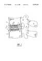
- FIG. 1illustrates a prior art threaded, cylindrical fusion cage positioned in the interbody space between two vertebral bodies
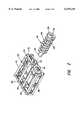
- FIG. 2is an exploded perspective view of the box cage device comprising a preferred embodiment of the invention
- FIG. 3is a side sectional view through two vertebrae of the spine and showing the device of FIG. 2 in the intervertebral space;
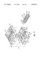
- FIG. 4is an exploded perspective view of the alternative preferred embodiment of the invention.
- FIG. 5is a side cross-sectional view like that of FIG. 3, but with the alternative preferred embodiment of FIG. 4 inserted;
- FIG. 6is a perspective view of another alternative embodiment of the invention.
- FIG. 1there is shown a cross-sectional view through two adjacent vertebral bodies 10 and 12 and shown for references purposes is the spinous process 14, the superior articular process 16, the inferior articular process 18 and the pedicle 20 of the vertebral bodies.
- the diskis comprised of two parts, namely a central part, called the nucleus, which is a gelatinous substance that is generally transparent and comprises approximately 88 percent water.
- a central partSurrounding the nucleus is a peripheral part called the annulus, which is made of concentric fibers. They enclose the nucleus in an inextensible casing, holding it under pressure to prevent prolapse.
- the nucleus of the discnormally acts as a spherical swivel joint, allowing tilting in the sagittal plane, flexion and extension tilting in the frontal plane as well as lateral flexion.
- the nucleusfurther permits rotation whereby one vertebra can swivel relative to another. Limited gliding movement of one vertebral body over another is also allowed for by the nucleus.
- a prior art cylindrical threaded cage device 22may be surgically implanted.
- the cage device 22comprises a cylindrical hollow screw body 24 having threads 26 formed thereon. Formed through the cylindrical screw device 22 at the root of the threads are a plurality of openings, as at 28, that are equally circumferentially spaced.
- a drill and tapare used to form threads in the facing surfaces of the vertebral bodies 10 and 12, allowing the screw or cage 22 to be threaded into the prepared opening.
- either a single such screw or a pair of screwsare inserted into the intervertebral space on opposite sides of the midline thereof to stabilize the vertebral bodies against motion. Bone chips or bone graft material is then packed within the hollow center of the screw.
- a generally rectangular box-like cage memberindicated generally by numeral 30, having four mutually perpendicular sidewalls 32, 34, 36 and 38 of a predetermined height dimension, allowing insertion between adjacent vertebral bodies using either an anterior, a posterior or a lateral approach.
- Extending between opposed sidewalls 32 and 36are a plurality of parallel, spaced-apart rib members 40.
- the rib membersare preferably triangular in shape as illustrated terminating in a ridge line 42.
- the opposed side edges 32 and 36also each include a circular aperture, as at 44 and 46, for receiving therein a locking screw member indicated generally by numeral 48.
- the locking screw 48includes a head 50 having a noncircular recess 52 formed inwardly of a face surface thereof for receiving an appropriate screw driver-like tool.
- the locking screwhas a raised thread 54 of a predetermined pitch slightly wider than the thickness dimension of the end walls 32 and 36.
- the root diameter of the locking screw 48allows it to be fitted through the aperture 44 and advanced until the tapered end portion 56 thereof passes into the aperture 46 of the sidewall 36.
- the crest diameter of the locking screw 48is made greater than the height dimension of the mutually perpendicular sidewalls 32, 34, 36 and 38 of the cage member 30, and, as such, the threads project outwardly beyond the level of the edges of the side walls.
- the hollow interior of the locking screw 48may be packed with bone chips and a plurality of openings, as at 58, are formed at the root of the threads leading to the hollow interior.
- the rectangular, box-like cage member 30is shown in its surgically implanted position between vertebral bodies 10 and 12 following a disectomy procedure to remove the damaged disk.
- the height dimension of the sidewalls, as well as their length dimension,are selected based upon the anatomy of the spinal column at the surgical site.
- the sidewalls of a cage member designed for placement between lumbar vertebral membersmay be in a range of from 10 mm to 18 mm, whereas a cage being placed in the cervical region may have a height dimension in a range of from 4 mm to 10 mm.
- the cage 30is driven into position using a hammer instrument.
- the exposed sharp edges 42 of the ribs 40dig into the bone surfaces of the plateaus 11 and 13 of the respective vertebral bodies 10 and 12. These ribs prevent lateral displacement of the cage 30.
- the locking screw 48is threadedly advanced into the apertures 44 and 46 of the cage member 30.
- the crests of the threads on the locking screw 48are designed to engage corresponding threads surgically formed in the plateaus 11 and 13 using a drill and tap. It will be recalled that the crest diameter of the locking screw is greater than the height dimension of the mutually perpendicular sidewalls such that the threads can engage the bone material, locking the cage device in position.
- the cage member 30has a generally open construction, including fenestrated sidewalls, it too can be packed with bone graft material which ultimately matures into a solid bony connection between the now-fused vertebral bodies. Because of the greater width dimension of the preferred embodiment as compared to the size of the prior art RAY and BAK cages, the adjacent vertebral bodies are precluded from movement as the patient leans to one side or the other or bends forward and backward. The greater stability afforded to the vertebral bodies enhances the ability for bone fusion to take place.
- the cage member 60comprises first and second halves 62 and 64, each having four mutually perpendicular sidewalls, as at 68-74 for cage half 62 and 76-82 for cage half 64.
- the length and width of the sidewalls of cage half 62are slightly larger than the corresponding dimensions of the cage half 64 whereby the cage half 62 will fit over the cage half 64 like the cover on a shirt box.
- Extending between opposed sidewalls 68 and 72 of the cage half 62are a plurality of ribs as at 84.
- the second cage half 64also includes a plurality of rib members 86 extending between opposed side edges 76 and 80 proximate the lower edge thereof.
- the side edge 68includes a V-shaped notch 88 extending through the thickness dimension thereof.
- Formed internally and affixed to the opposed side edge 72is an inwardly projecting boss 90, also having a V-shaped notch 92 formed therein and aligned with the notch 88.
- the side edge 76 of the lower box half 64includes a V-shaped notch 94.
- An inwardly projecting boss 96 on the box half 64includes a similar V-shaped notch 98.
- Extending longitudinally between end wall 68 and 72 of the upper cage half 62is a plate 99 having a series of regularly spaced, transversely extending notches 101 formed through the thickness dimension thereof.
- ribs 103Running along the side edges of the elongated plate 99 are triangular ribs 103. Similarly, spanning the box half 64 is a plate 105 having regularly spaced slots 107 formed therethrough triangular, downwardly projecting ribs 109 extend along the side edges of the plate 105.
- the upper and lower cage halvesmay be fabricated from a suitable metal or plastic with titanium being presently preferred because of its strength and lightweight properties.
- a locking screw 100Completing the assembly is a locking screw 100. It is of a generally uniform diameter over a majority of its length, but it tapers to a lesser diameter at an end 102 thereof.
- the screw 100has a head 104 with a tool receiving notch 106 formed therein.
- the threads 108 on the locking screw 100are of a predetermined pitch and have a crest diameter which is greater than the thickness dimension of the sidewalls 68 and 76. The pitch is such that the threads extend through the slots 101 and 107 of the plate members 99 and 105.
- FIG. 5there is shown a vertical cross-section through the vertebral members 10 and 12 with the box cage of the embodiment of FIG. 4 disposed in the intervertebral space.
- a locking screw 100 of a preselected diameteris advanced into the opening formed by the overlapping V-shaped notches 88 and 94 until the tapered distal end 102 thereof falls into the opening defined by the overlapping notches 92 and 98.
- Continued advancement of the locking screw 100will cause the cage halves 62 and 64 to spread apart relative to one another, thereby pressing the ribs 84, 86, 103 and 109 into the bone comprising the facing plateaus of the vertebral bodies 10 and 12.
- the degree of spreading of the box halves relative to one anotheris controlled by the selection of the root diameter of the locking screw 100. Because the threads are designed to be deep enough to allow the thread crests to project through the regularly spaced slots 101 and 107 in the plate members 99 and 105, they can penetrate into bone tissue of the plateaus of the adjacent vertebral bodies to inhibit displacement anteriorly and posteriorly.
- FIG. 6illustrates a further embodiment of the invention which is a slight modification of that shown in FIG. 4.
- the resulting cage memberindicated generally by numeral 110, is wedge-shaped.
- the assembled cagecomprises a box-like base 112 and a cover 114 dimensioned to fit over the base much like the cover on a shirt box.
- the height dimension of the rightmost ends of the base and coverare greater than the height dimension of the corresponding, opposed left side ends, thus providing the desired wedge shape.
- Upwardly projecting ribs 116 and 118extend along the rear and front side edges, respectfully, and likewise, the base 112 includes longitudinally extending ribs 120 and 122 projecting downwardly from the undersurface of the base along the side edges thereof.
- the right and left ends of the base 112 and the cover 114include semi-circular cut-outs as at 124 and 126 and 128-130 such that when the cover 114 is placed upon the base 112, circular apertures are formed. These apertures are adapted to receive a tapered screw 132 therein.
- the slope of the taper of the screwis designed to correspond to that of the cage assembly 110 such that when the screw 132 is threaded into the circular opening defined by arcuate cut-outs 124 and 126 and advanced by turning until the leading end 134 of the screw enters the circular aperture 128-130, further turning of the screw will raise the case cover 114 relative to its base 112, allowing adjustment of the cage height following positioning thereof between adjacent vertebral bodies.
- the screw 132is designed to have a relatively deep thread such that the periphery of the threads will project outward from the top of the cover 114 and the bottom of the base 112 so as to threadingly engage bone tissue of the plateaus of the adjacent vertebral bodies.
- the triangular ribs 116, 118, 120 and 122are adapted to dig into bone tissue to prevent lateral shifting of the cage between their adjacent vertebral bodies while the threaded screw 132 when advanced through the cage prevents anterior-posterior movement of the cage.
- the cageis again of an open construction, allowing it to be packed with bone particles for enhancing the fusion process.
- the stability afforded by the wedge-shaped cage constructionenhances the likelihood of a successful fusion.
- the rectangular cage members 30 (FIG. 2) and 60 (FIG. 4)are preferably fabricated from a body compatible material, such as stainless steel, titanium, carbon, alloy composites and combinations thereof.
- the locking screwcan also be formed from these materials with titanium, perhaps, being preferred.
- Electronic discharge machining techniquesmay be used to form the window openings in the side walls of the cage as well as the openings formed inwardly to the hollow center of the locking screws at the roots of the threads.
Landscapes
- Health & Medical Sciences (AREA)
- Engineering & Computer Science (AREA)
- Biomedical Technology (AREA)
- Orthopedic Medicine & Surgery (AREA)
- Neurology (AREA)
- Life Sciences & Earth Sciences (AREA)
- General Health & Medical Sciences (AREA)
- Veterinary Medicine (AREA)
- Heart & Thoracic Surgery (AREA)
- Public Health (AREA)
- Animal Behavior & Ethology (AREA)
- Transplantation (AREA)
- Cardiology (AREA)
- Vascular Medicine (AREA)
- Oral & Maxillofacial Surgery (AREA)
- Surgery (AREA)
- Nuclear Medicine, Radiotherapy & Molecular Imaging (AREA)
- Medical Informatics (AREA)
- Molecular Biology (AREA)
- Physical Education & Sports Medicine (AREA)
- Prostheses (AREA)
- Surgical Instruments (AREA)
Abstract
Description
This is a Continuation of application Ser. No. 09/157,928, filed on Sep. 21, 1998 now U.S. Pat. No. 6,090,143.
I. Field of the Invention
This invention relates generally to apparatus for effecting intervertebral body arthrodesis, and more particularly to an improved cage construction for reducing movement of adjacent vertebral bodies to thereby enhance bone growth and fusion.
II. Discussion of the Prior Art
Intervertebral body arthrodesis or fusion of a spine segment is indicated for symptomatic patients with intervertebral disk disease. The purpose of the fusion in these cases is to eliminate or reduce the amount of motion at that site and, possibly, the source of pain. For solid bone fusion between vertebral bodies, it is imperative that interbody movement be prevented if bone growth and fusion is to result.
When a vertebral body or disk is damaged, the spinal cord or nerve roots may be impinged. This causes extreme pain to the person, either in the back, neck or extremities. When all conservative drug treatments and minimally invasive procedures have been exhausted. A spinal stabilization with fusion may be the answer. It has long been thought that interbody fusion achieves relief of the patient's pain by correction of an existing mechanical deformation to its anatomic baseline and by the provision of stability to the spine segment to prevent future abnormal, i.e., excessive or pain-provoking motions. Spinal interbody fusion has, in theory, been the preferred surgical technique to achieve these goals. Unfortunately, this procedure has demonstrated widely varying results, with fusion rates ranging from 19 percent to 95 percent and satisfactory clinical results ranging from 14 percent to 93 percent. Devices, referred to as "fusion cages" have been developed to help stabilize adjacent vertebral bodies to be fused and to help promote solid bone fusion between such vertebral bodies. Fusion cages have been designed to correct existing mechanical deformation, to provide stability to the vertebral bodies until arthrodesis is achieved, provide the best possible environment for successful arthrodesis and to achieve this with limited morbidity associated with their use.
Ideally, interbody cage devices should restore disk height, place the annular fibers in a "normal" tension, create lordosis through the joined vertebral bodies, obtain sagittal balance through the segment, reduce subluxed facet joints, enlarge the neuorforaminal space, and restore to normal the proportion of weight bearing through the anterial spinal column.
Presently, there are two types of cages, round and square. Such cages vary in size for the area of the spine in which they are to be implanted, i.e., lumbar, thoracic or cervical. FIG. 1 illustrates a typical prior art fusion cage, such as the so-called BAK cage available from SpineTech of Minneapolis, Minn., and the RAY threaded fusion cage from Surgical Dynamics of Norwalk, Conn. These cages are threaded titanium cylinders having a longitudinal bore extending through them and with holes through the walls of the cylinder located at the roots of the threads. The longitudinal bore can be packed with bone particles and the holes allow bony ingrowth through the cages during the post-operative healing phase.
Depending upon the location of the damaged disk, either one or two such cages may be implanted between adjacent vertebral bodies. Generally, in the lumbar region, two such cage devices are employed and they are positioned on either side of the mid-line sufficiently far apart that they do not touch one another and generally will be about 3 mm from the anterior and posterior cortical margin of the end plates comprising the vertebral body. The cylindrical cages come in several diameters and the diameter chosen again depends upon the anatomy of the spine at the point of placement.
In implanting such devices, semi-circular laminotomies are performed on both lateral sides of the disk space and then the bone of the plateaus of the adjacent vertebral bodies are drilled and tapped to receive the threaded cylinders therein. Before closure, autologous bone graft material, usually harvested from the patient's iliac crest is packed within the hollow confines of the cylindrical threaded cage devices to enhance the opportunity for solid bone fusion.
It is imperative for successful fusion that stability of the adjacent vertebral bodies be maintained as bone growth takes place, even when the patient has returned to his/her daily activities. Motion through the operative segments leads to progressive mechanical loosening and eventual failure of implant or bone. Motion significantly decreases the chances of obtaining a solid bony arthrodesis. While the RAY threaded fusion cage and the BAK fusion cage constitute an improvement over earlier intercorporeal bone graft in spinal fusion following disk removal, instances have been reported where the cylindrical threaded cages move out of position, especially if the patient's daily activities involve bending from side-to-side or front-to-rear. When the body leans forward, the disk between the vertebral bodies compress on the anterior side of the spinal column while the posterior disk stretches. When the body leans to the left, the left side of the disk compresses and the right side stretches. Just the opposite occurs when leaning to the right. When two cylindrical threaded cages are placed in between the vertebral bodies following removal of the disk therebetween, the compression and stretching of the disk is gone, but the vertebral bodies open slightly as explained above. With the radius of the cylindrical threaded cages, rotation can exist from side-to-side. When vertebral body can roll over the side of the cylindrical cage, but this will not happen on a forward or backward movement, because there is no radius curve over the length of the cage member. A need exists for a fusion cage design that prevents front-to-back and side-to-side shifting of the adjacent vertebral bodies as the patient bends or leans. An overview of cage devices presently in use for interbody fusion are set forth in an article entitled "Spine Update--Lumbar Interbody Cages", by Bradley K. Weiner, M.D., Spine, Vol. 23, No. 5, Mar. 1, 1998, pp. 634-640.
In accordance with the present invention, there is provided an interbody implant for enhancing fusion of adjacent vertebral bodies that comprises a rectangular, box-like cage member having four mutually perpendicular sidewalls of a predetermined height dimension, allowing insertion between adjacent vertebral bodies. Extending between an opposed pair of the four sidewalls are a plurality of parallel, spaced-apart rib members. This opposed pair of sidewalls also include an aperture therethrough of a predetermined diameter.
Completing the device is a locking screw with threads of a predetermined pitch and a length dimension that allows threaded insertion into said apertures. The locking screw has a root diameter that is less than the predetermined diameter of the apertures formed through the opposed pair of sidewalls and a crest diameter that is greater than the predetermined height dimension of said opposed pair of sidewalls. Being so designed, the locking screw is adapted to threadingly engage tapped rounded grooves surgically created in the adjacent vertebral bodies when the cage member is inserted between the adjacent vertebral bodies and the locking screw is threaded into the apertures in the opposed pair of sidewalls. The locking screw prevents anterior/posterior displacement of the rectangular cage member while the plurality of parallel, spaced-apart rib members engage the adjacent vertebral bodies to prevent lateral shifting of the cage member with bending or leaning following insertion into the intervertebral space.
The foregoing features, objects and advantages of the present invention will become apparent to those skilled in the art from the following detailed description of a preferred embodiment, especially when considered in conjunction with the accompanying drawings in which like numerals in the several views refer to corresponding parts.
FIG. 1 illustrates a prior art threaded, cylindrical fusion cage positioned in the interbody space between two vertebral bodies;
FIG. 2 is an exploded perspective view of the box cage device comprising a preferred embodiment of the invention;
FIG. 3 is a side sectional view through two vertebrae of the spine and showing the device of FIG. 2 in the intervertebral space;
FIG. 4 is an exploded perspective view of the alternative preferred embodiment of the invention;
FIG. 5 is a side cross-sectional view like that of FIG. 3, but with the alternative preferred embodiment of FIG. 4 inserted; and
FIG. 6 is a perspective view of another alternative embodiment of the invention.
With reference to FIG. 1, there is shown a cross-sectional view through two adjacentvertebral bodies spinous process 14, the superiorarticular process 16, the inferiorarticular process 18 and thepedicle 20 of the vertebral bodies.
While not shown in FIG. 1, between adjacent vertebral bodies lies the intervertebral disk. The disk is comprised of two parts, namely a central part, called the nucleus, which is a gelatinous substance that is generally transparent and comprises approximately 88 percent water. Surrounding the nucleus is a peripheral part called the annulus, which is made of concentric fibers. They enclose the nucleus in an inextensible casing, holding it under pressure to prevent prolapse. The nucleus of the disc normally acts as a spherical swivel joint, allowing tilting in the sagittal plane, flexion and extension tilting in the frontal plane as well as lateral flexion. The nucleus further permits rotation whereby one vertebra can swivel relative to another. Limited gliding movement of one vertebral body over another is also allowed for by the nucleus.
Spinal injury due to compression loads or overextension may injure the disk resulting in a bulging of the nucleus beyond the annulus which often results in impingement of nucleus material on nerve structures, resulting in chronic pain. Where drugs or other less aggressive surgical procedures fail to alleviate the condition, a procedure known as spinal bone fusion may be in order. In this procedure, the affected disk is removed and means are provided for grafting bone between the adjacent vertebral bodies so that a rigid union of those vertebral bodies results.
Prior art techniques in achieving intervertebral fusion have involved the insertion of small pieces of bone, usually harvested from the pelvic bone, in the intervertebral space. Over time, the bone fragments grow into one unit. It is found, however, that movement at the location of the graft often prevents successful fusion and resulting stability.
To help stabilize thevertebral bodies graft material 20 solidifies, a prior art cylindrical threadedcage device 22 may be surgically implanted. Thecage device 22 comprises a cylindricalhollow screw body 24 havingthreads 26 formed thereon. Formed through thecylindrical screw device 22 at the root of the threads are a plurality of openings, as at 28, that are equally circumferentially spaced. During the surgical insertion thereof, a drill and tap are used to form threads in the facing surfaces of thevertebral bodies cage 22 to be threaded into the prepared opening. Depending upon the location in the spinal column where the injury is located, either a single such screw or a pair of screws are inserted into the intervertebral space on opposite sides of the midline thereof to stabilize the vertebral bodies against motion. Bone chips or bone graft material is then packed within the hollow center of the screw.
While prior art cylindrical cages inhibit gliding movement ofvertebral body 10 relative tovertebral body 12, tilting by way of lateral flexion and tilting in the sagittal plane can still result which necessarily impedes the formation of solid bone fusion. Leaning from side-to-side may also result in a slight rotational movement of the vertebral bodies over the cylindrical (rounded) surface of the cylindrical cages.
To obviate this problem, in accordance with the present invention, and as illustrated in the exploded view of FIG. 2, there is provided a generally rectangular box-like cage member, indicated generally bynumeral 30, having four mutuallyperpendicular sidewalls opposed sidewalls rib members 40. The rib members are preferably triangular in shape as illustrated terminating in aridge line 42.
The opposed side edges 32 and 36 also each include a circular aperture, as at 44 and 46, for receiving therein a locking screw member indicated generally bynumeral 48. The lockingscrew 48 includes ahead 50 having anoncircular recess 52 formed inwardly of a face surface thereof for receiving an appropriate screw driver-like tool. The locking screw has a raisedthread 54 of a predetermined pitch slightly wider than the thickness dimension of theend walls screw 48 allows it to be fitted through theaperture 44 and advanced until thetapered end portion 56 thereof passes into theaperture 46 of thesidewall 36. The crest diameter of the lockingscrew 48 is made greater than the height dimension of the mutuallyperpendicular sidewalls cage member 30, and, as such, the threads project outwardly beyond the level of the edges of the side walls.
As in the case of the prior art RAY and BAK cages, the hollow interior of the lockingscrew 48 may be packed with bone chips and a plurality of openings, as at 58, are formed at the root of the threads leading to the hollow interior.
Referring next to FIG. 3, the rectangular, box-like cage member 30 is shown in its surgically implanted position betweenvertebral bodies cage 30 is driven into position using a hammer instrument. As thecage member 30 is advanced into the intervertebral space, the exposedsharp edges 42 of theribs 40 dig into the bone surfaces of theplateaus 11 and 13 of the respectivevertebral bodies cage 30. To inhibit movement interiorly and posteriorly, the lockingscrew 48 is threadedly advanced into theapertures cage member 30. The crests of the threads on the lockingscrew 48 are designed to engage corresponding threads surgically formed in theplateaus 11 and 13 using a drill and tap. It will be recalled that the crest diameter of the locking screw is greater than the height dimension of the mutually perpendicular sidewalls such that the threads can engage the bone material, locking the cage device in position.
In that thecage member 30 has a generally open construction, including fenestrated sidewalls, it too can be packed with bone graft material which ultimately matures into a solid bony connection between the now-fused vertebral bodies. Because of the greater width dimension of the preferred embodiment as compared to the size of the prior art RAY and BAK cages, the adjacent vertebral bodies are precluded from movement as the patient leans to one side or the other or bends forward and backward. The greater stability afforded to the vertebral bodies enhances the ability for bone fusion to take place.
Referring now to the exploded view of FIG. 4, there is shown an alternative embodiment of the present invention that permits limited adjustment of the height dimension of the cage member. Here, thecage member 60 comprises first andsecond halves cage half 62 and 76-82 forcage half 64. The length and width of the sidewalls ofcage half 62 are slightly larger than the corresponding dimensions of thecage half 64 whereby thecage half 62 will fit over thecage half 64 like the cover on a shirt box. Extending betweenopposed sidewalls cage half 62 are a plurality of ribs as at 84. Likewise, thesecond cage half 64 also includes a plurality of rib members 86 extending between opposed side edges 76 and 80 proximate the lower edge thereof.
Theside edge 68 includes a V-shapednotch 88 extending through the thickness dimension thereof. Formed internally and affixed to theopposed side edge 72 is an inwardly projectingboss 90, also having a V-shapednotch 92 formed therein and aligned with thenotch 88. In a similar fashion, the side edge 76 of thelower box half 64 includes a V-shapednotch 94. An inwardly projectingboss 96 on thebox half 64 includes a similar V-shapednotch 98. Extending longitudinally betweenend wall upper cage half 62 is aplate 99 having a series of regularly spaced, transversely extendingnotches 101 formed through the thickness dimension thereof. Running along the side edges of theelongated plate 99 aretriangular ribs 103. Similarly, spanning thebox half 64 is aplate 105 having regularly spaced slots 107 formed therethrough triangular, downwardly projectingribs 109 extend along the side edges of theplate 105.
The upper and lower cage halves may be fabricated from a suitable metal or plastic with titanium being presently preferred because of its strength and lightweight properties.
Completing the assembly is a lockingscrew 100. It is of a generally uniform diameter over a majority of its length, but it tapers to a lesser diameter at anend 102 thereof. Thescrew 100 has ahead 104 with atool receiving notch 106 formed therein. Thethreads 108 on the lockingscrew 100 are of a predetermined pitch and have a crest diameter which is greater than the thickness dimension of thesidewalls 68 and 76. The pitch is such that the threads extend through theslots 101 and 107 of theplate members
Referring now to FIG. 5, there is shown a vertical cross-section through thevertebral members screw 100 of a preselected diameter is advanced into the opening formed by the overlapping V-shapednotches distal end 102 thereof falls into the opening defined by the overlappingnotches screw 100 will cause the cage halves 62 and 64 to spread apart relative to one another, thereby pressing theribs vertebral bodies screw 100. Because the threads are designed to be deep enough to allow the thread crests to project through the regularly spacedslots 101 and 107 in theplate members
FIG. 6 illustrates a further embodiment of the invention which is a slight modification of that shown in FIG. 4. In the embodiment of FIG. 6, rather than having a rectangular longitudinal cross-section, it is trapezoidal such that the resulting cage member, indicated generally bynumeral 110, is wedge-shaped. The assembled cage comprises a box-like base 112 and acover 114 dimensioned to fit over the base much like the cover on a shirt box. The height dimension of the rightmost ends of the base and cover are greater than the height dimension of the corresponding, opposed left side ends, thus providing the desired wedge shape. Upwardly projectingribs base 112 includes longitudinally extendingribs base 112 and thecover 114 include semi-circular cut-outs as at 124 and 126 and 128-130 such that when thecover 114 is placed upon thebase 112, circular apertures are formed. These apertures are adapted to receive atapered screw 132 therein. The slope of the taper of the screw is designed to correspond to that of thecage assembly 110 such that when thescrew 132 is threaded into the circular opening defined by arcuate cut-outs leading end 134 of the screw enters the circular aperture 128-130, further turning of the screw will raise thecase cover 114 relative to itsbase 112, allowing adjustment of the cage height following positioning thereof between adjacent vertebral bodies.
Again, thescrew 132 is designed to have a relatively deep thread such that the periphery of the threads will project outward from the top of thecover 114 and the bottom of the base 112 so as to threadingly engage bone tissue of the plateaus of the adjacent vertebral bodies.
Thus, as in the embodiment of FIG. 4, thetriangular ribs screw 132 when advanced through the cage prevents anterior-posterior movement of the cage. The cage is again of an open construction, allowing it to be packed with bone particles for enhancing the fusion process. The stability afforded by the wedge-shaped cage construction enhances the likelihood of a successful fusion.
The rectangular cage members 30 (FIG. 2) and 60 (FIG. 4) are preferably fabricated from a body compatible material, such as stainless steel, titanium, carbon, alloy composites and combinations thereof. Likewise, the locking screw can also be formed from these materials with titanium, perhaps, being preferred. Electronic discharge machining techniques may be used to form the window openings in the side walls of the cage as well as the openings formed inwardly to the hollow center of the locking screws at the roots of the threads.
This invention has been described herein in considerable detail in order to comply with the patent statutes and to provide those skilled in the art with the information needed to apply the novel principles and to construct and use such specialized components as are required. However, it is to be understood that the invention can be carried out by specifically different equipment and devices, and that various modifications, both as to the equipment and operating procedures, can be accomplished without departing from the scope of the invention itself.
Claims (10)
1. An interbody implant for enhancing fussion of adjacent vertebral bodies comprising:
(a) a cage member of generally rectangular cross-section having four mutually perpendicular sidewalls of predetermined height dimension allowing insertion between adjacent vertebral bodies, and with an opposed pair of said four sidewalls, each of said opposed pair of sidewalls including an aperture therethrough of a predetermined diameter; and
(b) a locking screw with threads of a predetermined pitch and a length allowing threaded insertion into said apertures, the locking screw having a root diameter less than said predetermined diameter and a crest diameter greater than the predetermined height dimension of the opposed pair of sidewalls and adapted to threadingly engage the adjacent vertebral bodies when the cage member is inserted between the adjacent bodies and the locking screw is threaded into the apertures in the opposed pair of sidewalls.
2. The interbody implant of claim 1 wherein the locking screw includes a longitudinal bore and openings of a predetermined size are formed through the locking screw at the roots of said threads for permitting bone growth therethrough.
3. The interbody implant of any one of claims 1-2 wherein the cage member is formed of a material selected from a class consisting of stainless steel, titanium carbon, alloy composites and combinations thereof.
4. The interbody implant of claim 1 wherein the cage member comprises:
(a) first and second cage halves, each having four mutually perpendicular sidewalls of a predetermined height dimension and with the length and width dimension of the four mutually perpendicular side walls of each of the first and second cage halves being such that the first cage half will fit within the second cage half.
5. The interbody implant as in claim 4 wherein the threaded insertion of the locking screw into the apertures spreads the first and second cage halves apart from one another for altering the effective height dimension of the cage member.
6. The interbody implant of claim 4 wherein a plurality of spaced apart rib members project outwardly above and below the opposed pair of sidewalls and adapted to engage the adjacent vertebral bodies for inhibiting lateral displacement of the cage member following implant.
7. The interbody implant of claim 4 wherein the locking screw includes a longitudinal bore and openings of a predetermined size are formed through the locking screw at the roots of said threads for permitting bone growth therethrough.
8. The interbody implant of any one of claims 4-7 wherein the first and second cage halves are formed of a material selected from a class consisting of stainless steel, titanium carbon alloy composites and combinations thereof.
9. The interbody implant of claim 1 wherein predetermined ones of the four mutually perpendicular sidewalls include openings formed through a thickness dimension thereof.
10. The interbody implant of claim 4 wherein predetermined ones of the four mutually perpendicular sidewalls include openings formed through a thickness dimension thereof.
Priority Applications (1)
| Application Number | Priority Date | Filing Date | Title |
|---|---|---|---|
| US09/436,593US6159245A (en) | 1998-09-21 | 1999-11-09 | Box cage for intervertebral body fusion |
Applications Claiming Priority (2)
| Application Number | Priority Date | Filing Date | Title |
|---|---|---|---|
| US09/157,928US6090143A (en) | 1998-09-21 | 1998-09-21 | Box cage for intervertebral body fusion |
| US09/436,593US6159245A (en) | 1998-09-21 | 1999-11-09 | Box cage for intervertebral body fusion |
Related Parent Applications (1)
| Application Number | Title | Priority Date | Filing Date |
|---|---|---|---|
| US09/157,928ContinuationUS6090143A (en) | 1998-09-21 | 1998-09-21 | Box cage for intervertebral body fusion |
Publications (1)
| Publication Number | Publication Date |
|---|---|
| US6159245Atrue US6159245A (en) | 2000-12-12 |
Family
ID=22565938
Family Applications (2)
| Application Number | Title | Priority Date | Filing Date |
|---|---|---|---|
| US09/157,928Expired - Fee RelatedUS6090143A (en) | 1998-09-21 | 1998-09-21 | Box cage for intervertebral body fusion |
| US09/436,593Expired - Fee RelatedUS6159245A (en) | 1998-09-21 | 1999-11-09 | Box cage for intervertebral body fusion |
Family Applications Before (1)
| Application Number | Title | Priority Date | Filing Date |
|---|---|---|---|
| US09/157,928Expired - Fee RelatedUS6090143A (en) | 1998-09-21 | 1998-09-21 | Box cage for intervertebral body fusion |
Country Status (6)
| Country | Link |
|---|---|
| US (2) | US6090143A (en) |
| EP (1) | EP1115355A2 (en) |
| JP (1) | JP2002543858A (en) |
| KR (1) | KR20010075238A (en) |
| AU (1) | AU6397999A (en) |
| WO (1) | WO2000016711A2 (en) |
Cited By (124)
| Publication number | Priority date | Publication date | Assignee | Title |
|---|---|---|---|---|
| US6436140B1 (en) | 1998-08-28 | 2002-08-20 | Sofamor S.N.C. | Expandable interbody fusion cage and method for insertion |
| US20020128652A1 (en)* | 1999-12-03 | 2002-09-12 | Ferree Bret A. | Version with markings to show changes made |
| US6454807B1 (en)* | 2000-11-30 | 2002-09-24 | Roger P. Jackson | Articulated expandable spinal fusion cage system |
| US6685742B1 (en) | 2002-11-12 | 2004-02-03 | Roger P. Jackson | Articulated anterior expandable spinal fusion cage system |
| US20040088055A1 (en)* | 2001-02-16 | 2004-05-06 | Hanson David A | Bone implants and methods |
| US20040122424A1 (en)* | 2000-01-15 | 2004-06-24 | Ferree Bret A. | Enhanced surface area spinal fusion devices and alignment apparatus therefor |
| US20040199256A1 (en)* | 2003-04-04 | 2004-10-07 | Chao-Jan Wang | Support device for supporting between spinal vertebrae |
| US20050021144A1 (en)* | 2003-07-23 | 2005-01-27 | Malberg Marc I. | Expandable spinal implant |
| US20050071006A1 (en)* | 2003-09-30 | 2005-03-31 | Kirschman David Louis | Spinal fusion system and method for fusing spinal bones |
| US7018415B1 (en)* | 2002-09-23 | 2006-03-28 | Sdgi Holdings, Inc. | Expandable spinal fusion device and methods of promoting spinal fusion |
| US7018416B2 (en) | 2000-07-06 | 2006-03-28 | Zimmer Spine, Inc. | Bone implants and methods |
| US20060089716A1 (en)* | 2004-10-27 | 2006-04-27 | Felix Brent A | Surgical implant |
| USD524942S1 (en) | 2005-05-23 | 2006-07-11 | Felix Brent A | Surgical implant |
| US20070123885A1 (en)* | 2003-09-30 | 2007-05-31 | X-Spine Systems, Inc. | Screw locking mechanism and method |
| US20070173938A1 (en)* | 2006-01-26 | 2007-07-26 | Spinal Generations, Llc | Interbody cage system |
| US7435261B1 (en)* | 2005-03-24 | 2008-10-14 | Frank Castro | Spinal implant and method of using spinal implant |
| US20080269901A1 (en)* | 2007-04-27 | 2008-10-30 | Baynham Bret O | Spinal implant |
| US20080275506A1 (en)* | 2007-04-27 | 2008-11-06 | Baynham Bret O | Spinal implant |
| US20090005816A1 (en)* | 2007-06-26 | 2009-01-01 | Denardo Andrew J | Spinal rod, insertion device, and method of using |
| US20090099661A1 (en)* | 2007-08-14 | 2009-04-16 | Jinia Bhattacharya | Multiple component osteoimplant |
| US20090222100A1 (en)* | 2008-02-28 | 2009-09-03 | Stryker Spine | Tool for implanting expandable intervertebral implant |
| US7641701B2 (en) | 2003-09-30 | 2010-01-05 | X-Spine Systems, Inc. | Spinal fusion system and method for fusing spinal bones |
| US20100042219A1 (en)* | 2008-08-14 | 2010-02-18 | Mark Darryl Antonacci | Expandable cage for intervertebral body fusion |
| US20100069912A1 (en)* | 2008-06-06 | 2010-03-18 | Mccormack Bruce M | Cervical distraction/implant delivery device |
| US7799081B2 (en) | 2004-09-14 | 2010-09-21 | Aeolin, Llc | System and method for spinal fusion |
| US20100241231A1 (en)* | 2009-02-20 | 2010-09-23 | Marino James F | Intervertebral fixation device |
| US7828849B2 (en) | 2003-02-03 | 2010-11-09 | Warsaw Orthopedic, Inc. | Expanding interbody implant and articulating inserter and method |
| US7837732B2 (en) | 2003-11-20 | 2010-11-23 | Warsaw Orthopedic, Inc. | Intervertebral body fusion cage with keels and implantation methods |
| US20100305701A1 (en)* | 2005-03-24 | 2010-12-02 | Cardinal Spine, Llc | Spinal implant |
| USD629519S1 (en)* | 2009-08-10 | 2010-12-21 | Horton Kenneth L | Dowel implant |
| US20100324679A1 (en)* | 2005-03-24 | 2010-12-23 | Frank Castro | Spinal implant and method of using spinal implant |
| US20100324682A1 (en)* | 2005-03-24 | 2010-12-23 | Frank Castro | Spinal implant |
| US20100331895A1 (en)* | 2005-08-15 | 2010-12-30 | Berend Linke | Osteosynthetic device |
| US20110009968A1 (en)* | 2006-12-29 | 2011-01-13 | Providence Medical Technology, Inc. | Cervical distraction method |
| US20110106171A1 (en)* | 2009-11-04 | 2011-05-05 | X-Spine Systems, Inc. | Screw implant and system and method for locking a screw in an implant plate |
| US20110144469A1 (en)* | 2008-05-07 | 2011-06-16 | Patraicia Connolly | Bacterial/Cellular Recognition Impedance Algorithm |
| US7963982B2 (en) | 2007-07-16 | 2011-06-21 | X-Spine Systems, Inc. | Implant plate screw locking system and screw having a locking member |
| US20110166660A1 (en)* | 2008-09-02 | 2011-07-07 | Synthes Usa, Llc | Implant with spiral anchor |
| US8016887B1 (en)* | 2005-03-24 | 2011-09-13 | Cardinal Spine, Llc | Spinal implant with overlay |
| US8088163B1 (en) | 2008-02-06 | 2012-01-03 | Kleiner Jeffrey B | Tools and methods for spinal fusion |
| USD656610S1 (en) | 2009-02-06 | 2012-03-27 | Kleiner Jeffrey B | Spinal distraction instrument |
| US8142508B1 (en) | 2007-07-02 | 2012-03-27 | Theken Spine, Llc | Spinal cage having deployable member which is removable |
| US8147521B1 (en)* | 2005-07-20 | 2012-04-03 | Nuvasive, Inc. | Systems and methods for treating spinal deformities |
| US8267997B2 (en) | 2007-11-12 | 2012-09-18 | Theken Spine, Llc | Vertebral interbody compression implant |
| US8292958B1 (en) | 2007-07-02 | 2012-10-23 | Theken Spine, Llc | Spinal cage having deployable member |
| US8361152B2 (en) | 2008-06-06 | 2013-01-29 | Providence Medical Technology, Inc. | Facet joint implants and delivery tools |
| US8361149B2 (en) | 2005-03-24 | 2013-01-29 | Cardinal Spine, Llc | Wedge-like spinal implant |
| US8366748B2 (en) | 2008-12-05 | 2013-02-05 | Kleiner Jeffrey | Apparatus and method of spinal implant and fusion |
| US8372152B2 (en) | 2003-09-30 | 2013-02-12 | X-Spine Systems, Inc. | Spinal fusion system utilizing an implant plate having at least one integral lock and ratchet lock |
| US8506636B2 (en) | 2006-09-08 | 2013-08-13 | Theken Spine, Llc | Offset radius lordosis |
| US8512409B1 (en) | 2012-02-10 | 2013-08-20 | Integral Spine Solutions, Inc. | Implant with outwardly extending fixation elements |
| US8535380B2 (en) | 2010-05-13 | 2013-09-17 | Stout Medical Group, L.P. | Fixation device and method |
| US8545562B1 (en) | 2007-07-02 | 2013-10-01 | Theken Spine, Llc | Deployable member for use with an intervertebral cage |
| CN103648443A (en)* | 2011-05-12 | 2014-03-19 | Lfc斯博拉卡公司 | Intervertebral implant for mutual situating of adjacent vertebrae |
| US8685031B2 (en) | 2009-09-18 | 2014-04-01 | Spinal Surgical Strategies, Llc | Bone graft delivery system |
| US8709042B2 (en) | 2004-09-21 | 2014-04-29 | Stout Medical Group, LP | Expandable support device and method of use |
| US8821553B2 (en) | 2003-09-30 | 2014-09-02 | X-Spine Systems, Inc. | Spinal fusion system utilizing an implant plate having at least one integral lock |
| WO2014158319A1 (en) | 2013-03-14 | 2014-10-02 | X-Spine Systems, Inc. | Spinal implant and assembly |
| US8864654B2 (en) | 2010-04-20 | 2014-10-21 | Jeffrey B. Kleiner | Method and apparatus for performing retro peritoneal dissection |
| US8864829B1 (en) | 2007-07-02 | 2014-10-21 | Theken Spine, Llc | Spinal cage having deployable member |
| US8900311B2 (en) | 2011-10-18 | 2014-12-02 | Lfc Spolka Z O.O. | Intervertebral spinal implant |
| US8906028B2 (en) | 2009-09-18 | 2014-12-09 | Spinal Surgical Strategies, Llc | Bone graft delivery device and method of using the same |
| USD723682S1 (en) | 2013-05-03 | 2015-03-03 | Spinal Surgical Strategies, Llc | Bone graft delivery tool |
| WO2015038301A1 (en) | 2013-09-13 | 2015-03-19 | X-Spine Systems, Inc. | Screw implant and system and method for locking a screw in an implant plate |
| US8986383B2 (en) | 2005-03-24 | 2015-03-24 | Igip, Llc | End cap and connector for a spinal implant |
| US9005288B2 (en) | 2008-01-09 | 2015-04-14 | Providence Medical Techonlogy, Inc. | Methods and apparatus for accessing and treating the facet joint |
| US9044284B2 (en) | 2010-09-29 | 2015-06-02 | Spinal Generations, Llc | Intervertebral insert system |
| US9050112B2 (en) | 2011-08-23 | 2015-06-09 | Flexmedex, LLC | Tissue removal device and method |
| US9060877B2 (en) | 2009-09-18 | 2015-06-23 | Spinal Surgical Strategies, Llc | Fusion cage with combined biological delivery system |
| USD732667S1 (en) | 2012-10-23 | 2015-06-23 | Providence Medical Technology, Inc. | Cage spinal implant |
| US9078706B2 (en) | 2003-09-30 | 2015-07-14 | X-Spine Systems, Inc. | Intervertebral fusion device utilizing multiple mobile uniaxial and bidirectional screw interface plates |
| WO2015130604A1 (en)* | 2014-02-25 | 2015-09-03 | Refai Technologies, Llc | Spinal cage device, system, and methods of assembly and use |
| US9149286B1 (en) | 2010-11-12 | 2015-10-06 | Flexmedex, LLC | Guidance tool and method for use |
| US9173694B2 (en) | 2009-09-18 | 2015-11-03 | Spinal Surgical Strategies, Llc | Fusion cage with combined biological delivery system |
| US9186193B2 (en) | 2009-09-18 | 2015-11-17 | Spinal Surgical Strategies, Llc | Fusion cage with combined biological delivery system |
| USD745156S1 (en) | 2012-10-23 | 2015-12-08 | Providence Medical Technology, Inc. | Spinal implant |
| US9216096B2 (en) | 2010-03-16 | 2015-12-22 | Pinnacle Spine Group, Llc | Intervertebral implants and related tools |
| US9247943B1 (en) | 2009-02-06 | 2016-02-02 | Kleiner Intellectual Property, Llc | Devices and methods for preparing an intervertebral workspace |
| USD750249S1 (en) | 2014-10-20 | 2016-02-23 | Spinal Surgical Strategies, Llc | Expandable fusion cage |
| US9320610B2 (en) | 2011-08-16 | 2016-04-26 | Stryker European Holdings I, Llc | Expandable implant |
| US9333086B2 (en) | 2008-06-06 | 2016-05-10 | Providence Medical Technology, Inc. | Spinal facet cage implant |
| US9380932B1 (en) | 2011-11-02 | 2016-07-05 | Pinnacle Spine Group, Llc | Retractor devices for minimally invasive access to the spine |
| US9381049B2 (en) | 2008-06-06 | 2016-07-05 | Providence Medical Technology, Inc. | Composite spinal facet implant with textured surfaces |
| US9402734B2 (en) | 2010-07-30 | 2016-08-02 | Igip, Llc | Spacer for spinal implant |
| US9456907B1 (en) | 2005-03-24 | 2016-10-04 | Igip, Llc | Extendable spinal implant |
| US9486263B2 (en) | 2009-11-04 | 2016-11-08 | X-Spine Systems, Inc. | Screw implant and system and method for locking a screw in an implant plate |
| US9629729B2 (en) | 2009-09-18 | 2017-04-25 | Spinal Surgical Strategies, Llc | Biological delivery system with adaptable fusion cage interface |
| US9717403B2 (en) | 2008-12-05 | 2017-08-01 | Jeffrey B. Kleiner | Method and apparatus for performing retro peritoneal dissection |
| USD797290S1 (en) | 2015-10-19 | 2017-09-12 | Spinal Surgical Strategies, Llc | Bone graft delivery tool |
| US9770339B2 (en) | 2005-07-14 | 2017-09-26 | Stout Medical Group, L.P. | Expandable support device and method of use |
| US9987052B2 (en) | 2015-02-24 | 2018-06-05 | X-Spine Systems, Inc. | Modular interspinous fixation system with threaded component |
| US10070968B2 (en) | 2010-08-24 | 2018-09-11 | Flexmedex, LLC | Support device and method for use |
| US10070970B2 (en) | 2013-03-14 | 2018-09-11 | Pinnacle Spine Group, Llc | Interbody implants and graft delivery systems |
| US10111755B2 (en) | 2017-02-24 | 2018-10-30 | Warsaw, Orthopedic, Inc. | Expanding interbody implant and articulating inserter and methods of use |
| US10149673B2 (en) | 2008-06-06 | 2018-12-11 | Providence Medical Technology, Inc. | Facet joint implants and delivery tools |
| US10166116B2 (en) | 2015-12-02 | 2019-01-01 | Brian Patrick Janowski | Helical lock spacer, instruments and methods |
| US10201375B2 (en) | 2014-05-28 | 2019-02-12 | Providence Medical Technology, Inc. | Lateral mass fixation system |
| USD841165S1 (en) | 2015-10-13 | 2019-02-19 | Providence Medical Technology, Inc. | Cervical cage |
| US10245159B1 (en) | 2009-09-18 | 2019-04-02 | Spinal Surgical Strategies, Llc | Bone graft delivery system and method for using same |
| US10285819B2 (en) | 2008-11-12 | 2019-05-14 | Stout Medical Group, L.P. | Fixation device and method |
| USD853560S1 (en) | 2008-10-09 | 2019-07-09 | Nuvasive, Inc. | Spinal implant insertion device |
| US10342675B2 (en) | 2013-03-11 | 2019-07-09 | Stryker European Holdings I, Llc | Expandable implant |
| US10342674B2 (en) | 2007-07-02 | 2019-07-09 | Theken Spine, Llc | Spinal cage having deployable member |
| US10470894B2 (en) | 2017-04-06 | 2019-11-12 | Warsaw Orthopedic, Inc. | Expanding interbody implant and articulating inserter and methods of use |
| CN110916736A (en)* | 2019-11-26 | 2020-03-27 | 杭州电子科技大学 | A kind of porous degradable screw and its manufacturing method |
| USD887552S1 (en) | 2016-07-01 | 2020-06-16 | Providence Medical Technology, Inc. | Cervical cage |
| US10682243B2 (en) | 2015-10-13 | 2020-06-16 | Providence Medical Technology, Inc. | Spinal joint implant delivery device and system |
| US10758289B2 (en) | 2006-05-01 | 2020-09-01 | Stout Medical Group, L.P. | Expandable support device and method of use |
| USD911525S1 (en) | 2019-06-21 | 2021-02-23 | Providence Medical Technology, Inc. | Spinal cage |
| US10940014B2 (en) | 2008-11-12 | 2021-03-09 | Stout Medical Group, L.P. | Fixation device and method |
| US10973656B2 (en) | 2009-09-18 | 2021-04-13 | Spinal Surgical Strategies, Inc. | Bone graft delivery system and method for using same |
| US11065039B2 (en) | 2016-06-28 | 2021-07-20 | Providence Medical Technology, Inc. | Spinal implant and methods of using the same |
| USD933230S1 (en) | 2019-04-15 | 2021-10-12 | Providence Medical Technology, Inc. | Cervical cage |
| US11224521B2 (en) | 2008-06-06 | 2022-01-18 | Providence Medical Technology, Inc. | Cervical distraction/implant delivery device |
| USD945621S1 (en) | 2020-02-27 | 2022-03-08 | Providence Medical Technology, Inc. | Spinal cage |
| US11272964B2 (en) | 2008-06-06 | 2022-03-15 | Providence Medical Technology, Inc. | Vertebral joint implants and delivery tools |
| US11648128B2 (en) | 2018-01-04 | 2023-05-16 | Providence Medical Technology, Inc. | Facet screw and delivery device |
| US11666455B2 (en) | 2009-09-18 | 2023-06-06 | Spinal Surgical Strategies, Inc., A Nevada Corporation | Bone graft delivery devices, systems and kits |
| US11871968B2 (en) | 2017-05-19 | 2024-01-16 | Providence Medical Technology, Inc. | Spinal fixation access and delivery system |
| US12004781B2 (en) | 2014-05-27 | 2024-06-11 | Providence Medical Technology, Inc. | Lateral mass fixation implant |
| US12144513B2 (en) | 2018-09-21 | 2024-11-19 | Providence Medical Technology, Inc. | Vertebral joint access and decortication devices and methods of using |
| US12186201B2 (en) | 2007-07-02 | 2025-01-07 | Theken Spine, Llc | Spinal cage having deployable member |
| US12279972B2 (en) | 2008-05-22 | 2025-04-22 | Spinal Surgical Strategies, Inc. | Spinal fusion cage system with inserter |
| USD1098431S1 (en) | 2023-02-27 | 2025-10-14 | Providence Medical Technology, Inc. | Spinal cage |
Families Citing this family (91)
| Publication number | Priority date | Publication date | Assignee | Title |
|---|---|---|---|---|
| US20010032017A1 (en) | 1999-12-30 | 2001-10-18 | Alfaro Arthur A. | Intervertebral implants |
| WO2001066048A1 (en)* | 2000-03-09 | 2001-09-13 | Osteotech, Inc. | Anterior lumbar spacer |
| US20030120274A1 (en) | 2000-10-20 | 2003-06-26 | Morris John W. | Implant retaining device |
| GR20000100414A (en)* | 2000-11-22 | 2002-09-26 | Χρηστος Καλαιτζης | Implant for the arthrodesis of the intrervertebral margin by anterior or posterior approach |
| US6773460B2 (en)* | 2000-12-05 | 2004-08-10 | Roger P. Jackson | Anterior variable expandable fusion cage |
| US6558424B2 (en)* | 2001-06-28 | 2003-05-06 | Depuy Acromed | Modular anatomic fusion device |
| US6855167B2 (en) | 2001-12-05 | 2005-02-15 | Osteotech, Inc. | Spinal intervertebral implant, interconnections for such implant and processes for making |
| US6923830B2 (en)* | 2002-02-02 | 2005-08-02 | Gary K. Michelson | Spinal fusion implant having deployable bone engaging projections |
| EP1482877B1 (en) | 2002-03-11 | 2007-05-30 | Spinal Concepts Inc. | Instrumentation for implanting spinal implant devices |
| US7094257B2 (en)* | 2003-02-14 | 2006-08-22 | Zimmer Spine, Inc. | Expandable intervertebral implant cage |
| AU2004212942A1 (en) | 2003-02-14 | 2004-09-02 | Depuy Spine, Inc. | In-situ formed intervertebral fusion device |
| WO2004084742A1 (en) | 2003-03-24 | 2004-10-07 | Theken Surgical Llc | Spinal implant adjustment device |
| US8333985B2 (en) | 2004-01-27 | 2012-12-18 | Warsaw Orthopedic, Inc. | Non-glycerol stabilized bone graft |
| US20050242101A1 (en)* | 2004-04-29 | 2005-11-03 | Skalitzky Michael J | Seal-coated plastic container for dispensing a pressurized product |
| US7544208B1 (en) | 2004-05-03 | 2009-06-09 | Theken Spine, Llc | Adjustable corpectomy apparatus |
| WO2008103781A2 (en) | 2007-02-21 | 2008-08-28 | Benvenue Medical, Inc. | Devices for treating the spine |
| AU2006279558B2 (en) | 2005-08-16 | 2012-05-17 | Izi Medical Products, Llc | Spinal tissue distraction devices |
| US8366773B2 (en) | 2005-08-16 | 2013-02-05 | Benvenue Medical, Inc. | Apparatus and method for treating bone |
| CN101272750A (en) | 2005-09-26 | 2008-09-24 | 华沙整形外科股份有限公司 | Transforaminal hybrid implant |
| CA2623448A1 (en)* | 2005-09-26 | 2007-03-29 | Frank J. Schwab | Hybrid intervertebral spinal fusion implant |
| US8764832B2 (en) | 2005-09-26 | 2014-07-01 | Warsaw Orhtopedic, Inc. | Anterior hybrid implant |
| US9439948B2 (en) | 2006-10-30 | 2016-09-13 | The Regents Of The University Of Michigan | Degradable cage coated with mineral layers for spinal interbody fusion |
| US12171904B2 (en) | 2006-10-30 | 2024-12-24 | Trs Holdings Llc | Mineral coated scaffolds |
| US8275594B2 (en)* | 2006-10-30 | 2012-09-25 | The Regents Of The University Of Michigan | Engineered scaffolds for intervertebral disc repair and regeneration and for articulating joint repair and regeneration |
| WO2008070863A2 (en) | 2006-12-07 | 2008-06-12 | Interventional Spine, Inc. | Intervertebral implant |
| US8372157B2 (en) | 2007-02-12 | 2013-02-12 | Warsaw Orthopedic, Inc. | Joint revision implant |
| EP2124778B1 (en) | 2007-02-21 | 2019-09-25 | Benvenue Medical, Inc. | Devices for treating the spine |
| US8123811B2 (en)* | 2007-04-27 | 2012-02-28 | Atlas Spine, Inc. | Cervical implant |
| US8480715B2 (en) | 2007-05-22 | 2013-07-09 | Zimmer Spine, Inc. | Spinal implant system and method |
| US8900307B2 (en) | 2007-06-26 | 2014-12-02 | DePuy Synthes Products, LLC | Highly lordosed fusion cage |
| US8852280B2 (en)* | 2007-09-27 | 2014-10-07 | Warsaw Orthopedic, Inc. | Intervertebral implant |
| EP2237748B1 (en) | 2008-01-17 | 2012-09-05 | Synthes GmbH | An expandable intervertebral implant |
| US8083796B1 (en) | 2008-02-29 | 2011-12-27 | Nuvasive, Inc. | Implants and methods for spinal fusion |
| US8936641B2 (en) | 2008-04-05 | 2015-01-20 | DePuy Synthes Products, LLC | Expandable intervertebral implant |
| US8535327B2 (en) | 2009-03-17 | 2013-09-17 | Benvenue Medical, Inc. | Delivery apparatus for use with implantable medical devices |
| US9526620B2 (en) | 2009-03-30 | 2016-12-27 | DePuy Synthes Products, Inc. | Zero profile spinal fusion cage |
| US9095444B2 (en) | 2009-07-24 | 2015-08-04 | Warsaw Orthopedic, Inc. | Implant with an interference fit fastener |
| EP2485682A4 (en)* | 2009-11-10 | 2013-10-23 | Zimmer Spine Inc | TISSUE SPACING ELEMENT IMPLANT, IMPLANTATION TOOL, AND METHODS OF USING THE SAME |
| US9393129B2 (en) | 2009-12-10 | 2016-07-19 | DePuy Synthes Products, Inc. | Bellows-like expandable interbody fusion cage |
| US8979860B2 (en) | 2010-06-24 | 2015-03-17 | DePuy Synthes Products. LLC | Enhanced cage insertion device |
| US9907560B2 (en) | 2010-06-24 | 2018-03-06 | DePuy Synthes Products, Inc. | Flexible vertebral body shavers |
| US8623091B2 (en) | 2010-06-29 | 2014-01-07 | DePuy Synthes Products, LLC | Distractible intervertebral implant |
| US9402732B2 (en) | 2010-10-11 | 2016-08-02 | DePuy Synthes Products, Inc. | Expandable interspinous process spacer implant |
| US20120116457A1 (en)* | 2010-11-06 | 2012-05-10 | Limited Liability Company; | Stabilizer for assisting stabilization of a spinal implant and method of using the stabilizer |
| US8454694B2 (en) | 2011-03-03 | 2013-06-04 | Warsaw Orthopedic, Inc. | Interbody device and plate for spinal stabilization and instruments for positioning same |
| US8814873B2 (en) | 2011-06-24 | 2014-08-26 | Benvenue Medical, Inc. | Devices and methods for treating bone tissue |
| US9198764B2 (en) | 2012-01-31 | 2015-12-01 | Blackstone Medical, Inc. | Intervertebral disc prosthesis and method |
| WO2013149134A2 (en)* | 2012-03-30 | 2013-10-03 | Olympus Biotech Corporation | Alif spinal implant |
| US8900310B2 (en) | 2012-04-05 | 2014-12-02 | Zimmer Spine, Inc. | Interbody spacer |
| US8475533B1 (en) | 2012-09-27 | 2013-07-02 | Igip, Llc | System and stabilizer for spinal implant and methods of assisting stabilization of spinal implant |
| US9717601B2 (en) | 2013-02-28 | 2017-08-01 | DePuy Synthes Products, Inc. | Expandable intervertebral implant, system, kit and method |
| US9522070B2 (en) | 2013-03-07 | 2016-12-20 | Interventional Spine, Inc. | Intervertebral implant |
| US10085783B2 (en) | 2013-03-14 | 2018-10-02 | Izi Medical Products, Llc | Devices and methods for treating bone tissue |
| US11491024B2 (en) | 2013-03-15 | 2022-11-08 | Atlas Spine, Inc. | PLIF hinged spacer |
| US9889020B2 (en) | 2013-03-15 | 2018-02-13 | Atlas Spine, Inc. | PLIF hinged spacer |
| US9421111B2 (en)* | 2013-03-15 | 2016-08-23 | Atlas Spine, Inc. | PLIF hinged spacer |
| US10034769B2 (en) | 2014-08-26 | 2018-07-31 | Atlas Spine, Inc. | Spinal implant device |
| US10117752B2 (en) | 2015-02-26 | 2018-11-06 | Uncinate Joint, Llc | Uncinate joint stabilizers and associated systems and methods |
| US10433829B2 (en) | 2015-02-26 | 2019-10-08 | Uncinate Joint, Llc | Stabilization of cervical spine utilizing stabilization of uncinate joints and across disc space |
| US11426290B2 (en) | 2015-03-06 | 2022-08-30 | DePuy Synthes Products, Inc. | Expandable intervertebral implant, system, kit and method |
| US10492921B2 (en) | 2015-04-29 | 2019-12-03 | Institute for Musculoskeletal Science and Education, Ltd. | Implant with arched bone contacting elements |
| US10449051B2 (en) | 2015-04-29 | 2019-10-22 | Institute for Musculoskeletal Science and Education, Ltd. | Implant with curved bone contacting elements |
| US10709570B2 (en) | 2015-04-29 | 2020-07-14 | Institute for Musculoskeletal Science and Education, Ltd. | Implant with a diagonal insertion axis |
| JP6768001B2 (en) | 2015-04-29 | 2020-10-14 | インスティテュート フォー マスキュロスケレタル サイエンス アンド エジュケイション,リミテッド | Coiled implants and systems and how to make them |
| US9820867B2 (en)* | 2015-05-13 | 2017-11-21 | Gil Tepper | Three column spinal fixation implants and associated surgical methods |
| CN105326587B (en)* | 2015-12-09 | 2017-05-03 | 北京市富乐科技开发有限公司 | Opening type interbody fusion cage |
| US10034699B2 (en) | 2016-01-14 | 2018-07-31 | DePuy Synthes Products, Inc. | Stand-alone fusion implant secured by in-line fixation |
| US11510788B2 (en) | 2016-06-28 | 2022-11-29 | Eit Emerging Implant Technologies Gmbh | Expandable, angularly adjustable intervertebral cages |
| EP3474784A2 (en) | 2016-06-28 | 2019-05-01 | Eit Emerging Implant Technologies GmbH | Expandable and angularly adjustable intervertebral cages with articulating joint |
| US10478312B2 (en) | 2016-10-25 | 2019-11-19 | Institute for Musculoskeletal Science and Education, Ltd. | Implant with protected fusion zones |
| US11033394B2 (en) | 2016-10-25 | 2021-06-15 | Institute for Musculoskeletal Science and Education, Ltd. | Implant with multi-layer bone interfacing lattice |
| US10888433B2 (en) | 2016-12-14 | 2021-01-12 | DePuy Synthes Products, Inc. | Intervertebral implant inserter and related methods |
| US10512549B2 (en) | 2017-03-13 | 2019-12-24 | Institute for Musculoskeletal Science and Education, Ltd. | Implant with structural members arranged around a ring |
| US10357377B2 (en) | 2017-03-13 | 2019-07-23 | Institute for Musculoskeletal Science and Education, Ltd. | Implant with bone contacting elements having helical and undulating planar geometries |
| US10667924B2 (en) | 2017-03-13 | 2020-06-02 | Institute for Musculoskeletal Science and Education, Ltd. | Corpectomy implant |
| US10213317B2 (en) | 2017-03-13 | 2019-02-26 | Institute for Musculoskeletal Science and Education | Implant with supported helical members |
| US10398563B2 (en) | 2017-05-08 | 2019-09-03 | Medos International Sarl | Expandable cage |
| US11344424B2 (en) | 2017-06-14 | 2022-05-31 | Medos International Sarl | Expandable intervertebral implant and related methods |
| US10940016B2 (en) | 2017-07-05 | 2021-03-09 | Medos International Sarl | Expandable intervertebral fusion cage |
| EP3654875B1 (en)* | 2017-07-18 | 2024-08-28 | Blue Sky Technologies, LLC | Joint arthrodesis system |
| US10893945B2 (en) | 2017-09-29 | 2021-01-19 | Luis E Duarte | Bone cage including offset sets of protrusions within a bone ingrowth cavity and related methods |
| US10940015B2 (en) | 2017-11-21 | 2021-03-09 | Institute for Musculoskeletal Science and Education, Ltd. | Implant with improved flow characteristics |
| US10744001B2 (en) | 2017-11-21 | 2020-08-18 | Institute for Musculoskeletal Science and Education, Ltd. | Implant with improved bone contact |
| US10695192B2 (en) | 2018-01-31 | 2020-06-30 | Institute for Musculoskeletal Science and Education, Ltd. | Implant with internal support members |
| CN109009581B (en)* | 2018-09-13 | 2024-02-02 | 陕西东望科技有限公司 | Assembled artificial vertebral body |
| US11446156B2 (en) | 2018-10-25 | 2022-09-20 | Medos International Sarl | Expandable intervertebral implant, inserter instrument, and related methods |
| IT201900003947A1 (en)* | 2019-03-19 | 2020-09-19 | Mt Ortho S R L | Granule in biocompatible metal material for vertebroplasty. |
| US11426286B2 (en) | 2020-03-06 | 2022-08-30 | Eit Emerging Implant Technologies Gmbh | Expandable intervertebral implant |
| US11850160B2 (en) | 2021-03-26 | 2023-12-26 | Medos International Sarl | Expandable lordotic intervertebral fusion cage |
| US11752009B2 (en) | 2021-04-06 | 2023-09-12 | Medos International Sarl | Expandable intervertebral fusion cage |
| US12090064B2 (en) | 2022-03-01 | 2024-09-17 | Medos International Sarl | Stabilization members for expandable intervertebral implants, and related systems and methods |
Citations (1)
| Publication number | Priority date | Publication date | Assignee | Title |
|---|---|---|---|---|
| US5888228A (en)* | 1995-10-20 | 1999-03-30 | Synthes (U.S.A.) | Intervertebral implant with cage and rotating element |
Family Cites Families (4)
| Publication number | Priority date | Publication date | Assignee | Title |
|---|---|---|---|---|
| FR2753368B1 (en)* | 1996-09-13 | 1999-01-08 | Chauvin Jean Luc | EXPANSIONAL OSTEOSYNTHESIS CAGE |
| US5782832A (en)* | 1996-10-01 | 1998-07-21 | Surgical Dynamics, Inc. | Spinal fusion implant and method of insertion thereof |
| FR2754170B1 (en)* | 1996-10-03 | 1998-12-24 | Medinov Amp | INTERSOMATIC VERTEBRAL ARTHRODESIS PROSTHESIS |
| US5865848A (en)* | 1997-09-12 | 1999-02-02 | Artifex, Ltd. | Dynamic intervertebral spacer and method of use |
- 1998
- 1998-09-21USUS09/157,928patent/US6090143A/ennot_activeExpired - Fee Related
- 1999
- 1999-09-21JPJP2000573674Apatent/JP2002543858A/enactivePending
- 1999-09-21KRKR1020017003583Apatent/KR20010075238A/ennot_activeWithdrawn
- 1999-09-21AUAU63979/99Apatent/AU6397999A/ennot_activeAbandoned
- 1999-09-21EPEP99951562Apatent/EP1115355A2/ennot_activeWithdrawn
- 1999-09-21WOPCT/US1999/022001patent/WO2000016711A2/ennot_activeApplication Discontinuation
- 1999-11-09USUS09/436,593patent/US6159245A/ennot_activeExpired - Fee Related
Patent Citations (1)
| Publication number | Priority date | Publication date | Assignee | Title |
|---|---|---|---|---|
| US5888228A (en)* | 1995-10-20 | 1999-03-30 | Synthes (U.S.A.) | Intervertebral implant with cage and rotating element |
Non-Patent Citations (8)
| Title |
|---|
| Onesti, Stephen et al. Neurosurgery , vol. 42, No. 1, Jan. 1998, pp. 200 204 Instrumentation, technique and Technology .* |
| Onesti, Stephen et al. Neurosurgery, vol. 42, No. 1, Jan. 1998, pp. 200-204 "Instrumentation, technique and Technology". |
| Ray, Charles, Neurosurgery Quarterly , vol. 7, No. 2, pp. 135 156, Spinal Interbody Fusions: A Review, Featuring New Generation Techniques .* |
| Ray, Charles, Neurosurgery Quarterly, vol. 7, No. 2, pp. 135-156, "Spinal Interbody Fusions: A Review, Featuring New Generation Techniques". |
| Ray, Charles, Spine , vol. 22, No. 6, pp. 681 685, Threaded Fusion Cages for Lumbar Interbody Fusions: An Economic Comparison with 360 Fusions .* |
| Ray, Charles, Spine, vol. 22, No. 6, pp. 681-685, "Threaded Fusion Cages for Lumbar Interbody Fusions: An Economic Comparison with 360° Fusions". |
| Weiner, Bradley, et al., Spine , vol. 23, No. 5, pp. 634 640, Spine Update Lumbar Interbody Cages Copyright, 1998.* |
| Weiner, Bradley, et al., Spine, vol. 23, No. 5, pp. 634-640, "Spine Update Lumbar Interbody Cages" Copyright, 1998. |
Cited By (264)
| Publication number | Priority date | Publication date | Assignee | Title |
|---|---|---|---|---|
| US7431735B2 (en) | 1998-08-28 | 2008-10-07 | Sofamor S.N.C. | Expandable interbody fusion cage |
| US20040249466A1 (en)* | 1998-08-28 | 2004-12-09 | Mingyan Liu | Expandable interbody fusion cage |
| US6436140B1 (en) | 1998-08-28 | 2002-08-20 | Sofamor S.N.C. | Expandable interbody fusion cage and method for insertion |
| US20020128652A1 (en)* | 1999-12-03 | 2002-09-12 | Ferree Bret A. | Version with markings to show changes made |
| US20040122424A1 (en)* | 2000-01-15 | 2004-06-24 | Ferree Bret A. | Enhanced surface area spinal fusion devices and alignment apparatus therefor |
| US7018416B2 (en) | 2000-07-06 | 2006-03-28 | Zimmer Spine, Inc. | Bone implants and methods |
| US6454807B1 (en)* | 2000-11-30 | 2002-09-24 | Roger P. Jackson | Articulated expandable spinal fusion cage system |
| US20040088055A1 (en)* | 2001-02-16 | 2004-05-06 | Hanson David A | Bone implants and methods |
| US20070055377A1 (en)* | 2001-02-16 | 2007-03-08 | Zimmer Spine, Inc. | Bone implants and methods |
| US7018415B1 (en)* | 2002-09-23 | 2006-03-28 | Sdgi Holdings, Inc. | Expandable spinal fusion device and methods of promoting spinal fusion |
| US6685742B1 (en) | 2002-11-12 | 2004-02-03 | Roger P. Jackson | Articulated anterior expandable spinal fusion cage system |
| US20040254643A1 (en)* | 2002-11-12 | 2004-12-16 | Jackson Roger P. | Articulated anterior expandable spinal fusion cage system |
| US8579981B2 (en) | 2003-02-03 | 2013-11-12 | Warsaw Orthopedic, Inc. | Expanding interbody implant and articulating inserter and method |
| US10265191B2 (en) | 2003-02-03 | 2019-04-23 | Warsaw Orthopedic, Inc. | Expanding interbody implant and articulating inserter and method |
| US8986389B2 (en) | 2003-02-03 | 2015-03-24 | Warsaw, Orthopedic, Inc. | Expanding interbody implant and articulating inserter and method |
| US9750617B2 (en) | 2003-02-03 | 2017-09-05 | Warsaw Orthopedic, Inc. | Expanding interbody implant and articulating inserter and method |
| US7828849B2 (en) | 2003-02-03 | 2010-11-09 | Warsaw Orthopedic, Inc. | Expanding interbody implant and articulating inserter and method |
| US9271846B2 (en) | 2003-02-03 | 2016-03-01 | Warsaw Orthopedic, Inc. | Expanding interbody implant and articulating inserter and method |
| US20040199256A1 (en)* | 2003-04-04 | 2004-10-07 | Chao-Jan Wang | Support device for supporting between spinal vertebrae |
| US20050021144A1 (en)* | 2003-07-23 | 2005-01-27 | Malberg Marc I. | Expandable spinal implant |
| US7318839B2 (en) | 2003-07-23 | 2008-01-15 | Ebi, L.P. | Expandable spinal implant |
| US20070288018A1 (en)* | 2003-07-23 | 2007-12-13 | Ebi, L.P. | Expandable spinal implant |
| US20090030458A1 (en)* | 2003-07-23 | 2009-01-29 | Ebi, Llc | Method for stabilizing spine |
| US8986384B2 (en) | 2003-07-23 | 2015-03-24 | Resspond Spinal Systems | Method for stabilizing spine |
| US8361148B2 (en) | 2003-07-23 | 2013-01-29 | Marc I. Malberg | Method for stabilizing spine |
| US7465317B2 (en) | 2003-07-23 | 2008-12-16 | Ebi, Llc | Expandable spinal implant |
| US8734493B2 (en) | 2003-09-30 | 2014-05-27 | X-Spine Systems, Inc. | Screw locking mechanism and method |
| EP2263616A1 (en) | 2003-09-30 | 2010-12-22 | X-Spine Systems, Inc. | A prosthetic implant plate |
| US8821553B2 (en) | 2003-09-30 | 2014-09-02 | X-Spine Systems, Inc. | Spinal fusion system utilizing an implant plate having at least one integral lock |
| US8795370B2 (en) | 2003-09-30 | 2014-08-05 | X-Spine Systems, Inc. | Fusion system and method for fusing spinal bones |
| US9078706B2 (en) | 2003-09-30 | 2015-07-14 | X-Spine Systems, Inc. | Intervertebral fusion device utilizing multiple mobile uniaxial and bidirectional screw interface plates |
| US20050071006A1 (en)* | 2003-09-30 | 2005-03-31 | Kirschman David Louis | Spinal fusion system and method for fusing spinal bones |
| US7641701B2 (en) | 2003-09-30 | 2010-01-05 | X-Spine Systems, Inc. | Spinal fusion system and method for fusing spinal bones |
| US7655028B2 (en) | 2003-09-30 | 2010-02-02 | X-Spine Systems, Inc. | Spinal fusion system and method for fusing spinal bones |
| US8282682B2 (en) | 2003-09-30 | 2012-10-09 | X-Spine Systems, Inc. | Fusion system and method for fusing spinal bones |
| US8062367B2 (en) | 2003-09-30 | 2011-11-22 | X-Spine Systems, Inc. | Screw locking mechanism and method |
| US20100145453A1 (en)* | 2003-09-30 | 2010-06-10 | X-Spine Systems, Inc. | Fusion system and method for fusing spinal bones |
| EP2263615A1 (en) | 2003-09-30 | 2010-12-22 | X-Spine Systems, Inc. | A spinal fusion system |
| US8372152B2 (en) | 2003-09-30 | 2013-02-12 | X-Spine Systems, Inc. | Spinal fusion system utilizing an implant plate having at least one integral lock and ratchet lock |
| US7182782B2 (en) | 2003-09-30 | 2007-02-27 | X-Spine Systems, Inc. | Spinal fusion system and method for fusing spinal bones |
| US20070123885A1 (en)* | 2003-09-30 | 2007-05-31 | X-Spine Systems, Inc. | Screw locking mechanism and method |
| US7837732B2 (en) | 2003-11-20 | 2010-11-23 | Warsaw Orthopedic, Inc. | Intervertebral body fusion cage with keels and implantation methods |
| US8491653B2 (en) | 2003-11-20 | 2013-07-23 | Warsaw Orthopedic, Inc. | Intervertebral body fusion cage with keels and implantation methods |
| EP2380527A1 (en) | 2004-06-02 | 2011-10-26 | X-Spine Systems, Inc. | Spinal fusion system and method for fusing spinal bones |
| US7799081B2 (en) | 2004-09-14 | 2010-09-21 | Aeolin, Llc | System and method for spinal fusion |
| US8562683B2 (en) | 2004-09-14 | 2013-10-22 | Aeolin Llc | System and method for spinal fusion |
| US8709042B2 (en) | 2004-09-21 | 2014-04-29 | Stout Medical Group, LP | Expandable support device and method of use |
| US9259329B2 (en) | 2004-09-21 | 2016-02-16 | Stout Medical Group, L.P. | Expandable support device and method of use |
| US11051954B2 (en) | 2004-09-21 | 2021-07-06 | Stout Medical Group, L.P. | Expandable support device and method of use |
| US9314349B2 (en) | 2004-09-21 | 2016-04-19 | Stout Medical Group, L.P. | Expandable support device and method of use |
| US7794500B2 (en) | 2004-10-27 | 2010-09-14 | Felix Brent A | Surgical implant |
| US20060089716A1 (en)* | 2004-10-27 | 2006-04-27 | Felix Brent A | Surgical implant |
| US8246683B2 (en) | 2005-03-24 | 2012-08-21 | Cardinal Spine, Llc | Spinal implant |
| US8673006B2 (en) | 2005-03-24 | 2014-03-18 | Igip, Llc | Spinal implant |
| US9259323B2 (en) | 2005-03-24 | 2016-02-16 | Igip, Llc | End cap and connector for a spinal implant |
| US7435261B1 (en)* | 2005-03-24 | 2008-10-14 | Frank Castro | Spinal implant and method of using spinal implant |
| US7942932B2 (en) | 2005-03-24 | 2011-05-17 | Cardinal Spine, Llc | Spinal implant and method of using spinal implant |
| US8986383B2 (en) | 2005-03-24 | 2015-03-24 | Igip, Llc | End cap and connector for a spinal implant |
| US9456907B1 (en) | 2005-03-24 | 2016-10-04 | Igip, Llc | Extendable spinal implant |
| US9011540B1 (en) | 2005-03-24 | 2015-04-21 | Igip, Llc | Overlay or implant and method for improving stability of the implant |
| US8002832B2 (en) | 2005-03-24 | 2011-08-23 | Cardinal Spine, Llc | Spinal implant and method of using spinal implant |
| US8016887B1 (en)* | 2005-03-24 | 2011-09-13 | Cardinal Spine, Llc | Spinal implant with overlay |
| US20100324682A1 (en)* | 2005-03-24 | 2010-12-23 | Frank Castro | Spinal implant |
| US20100324685A1 (en)* | 2005-03-24 | 2010-12-23 | Frank Castro | Spinal implant and method of using spinal implant |
| US20100324678A1 (en)* | 2005-03-24 | 2010-12-23 | Frank Castro | Spinal implant and method of using spinal implant |
| US8361149B2 (en) | 2005-03-24 | 2013-01-29 | Cardinal Spine, Llc | Wedge-like spinal implant |
| US20100324679A1 (en)* | 2005-03-24 | 2010-12-23 | Frank Castro | Spinal implant and method of using spinal implant |
| US8226718B2 (en) | 2005-03-24 | 2012-07-24 | Cardinal Spine, Llc | Spinal implant and method of using spinal implant |
| US20100305701A1 (en)* | 2005-03-24 | 2010-12-02 | Cardinal Spine, Llc | Spinal implant |
| USD524942S1 (en) | 2005-05-23 | 2006-07-11 | Felix Brent A | Surgical implant |
| US9770339B2 (en) | 2005-07-14 | 2017-09-26 | Stout Medical Group, L.P. | Expandable support device and method of use |
| US9566090B1 (en) | 2005-07-20 | 2017-02-14 | Nuvasive, Inc. | Systems and methods for treating spinal deformities |
| US8652177B1 (en) | 2005-07-20 | 2014-02-18 | Nuvasive, Inc. | Systems and methods for treating spinal deformities |
| US10195047B2 (en) | 2005-07-20 | 2019-02-05 | Nuvasive, Inc. | Systems and methods for treating spinal deformities |
| US8147521B1 (en)* | 2005-07-20 | 2012-04-03 | Nuvasive, Inc. | Systems and methods for treating spinal deformities |
| US11013611B2 (en) | 2005-07-20 | 2021-05-25 | Nuvasive, Inc. | Systems and methods for treating spinal deformities |
| US9125696B2 (en)* | 2005-08-15 | 2015-09-08 | DePuy Synthes Products, Inc. | Osteosynthetic device |
| US20100331895A1 (en)* | 2005-08-15 | 2010-12-30 | Berend Linke | Osteosynthetic device |
| US20070173938A1 (en)* | 2006-01-26 | 2007-07-26 | Spinal Generations, Llc | Interbody cage system |
| US8419795B2 (en) | 2006-01-26 | 2013-04-16 | Spinal Generations, Llc | Interbody cage system |
| US20090248164A1 (en)* | 2006-01-26 | 2009-10-01 | Spinal Generations, Llc | Interbody cage system |
| US7588599B2 (en) | 2006-01-26 | 2009-09-15 | Spinal Generations, Llc | Interbody cage system |
| US10813677B2 (en) | 2006-05-01 | 2020-10-27 | Stout Medical Group, L.P. | Expandable support device and method of use |
| US11141208B2 (en) | 2006-05-01 | 2021-10-12 | Stout Medical Group, L.P. | Expandable support device and method of use |
| US10758289B2 (en) | 2006-05-01 | 2020-09-01 | Stout Medical Group, L.P. | Expandable support device and method of use |
| US8506636B2 (en) | 2006-09-08 | 2013-08-13 | Theken Spine, Llc | Offset radius lordosis |
| US11285010B2 (en) | 2006-12-29 | 2022-03-29 | Providence Medical Technology, Inc. | Cervical distraction method |
| US20110009968A1 (en)* | 2006-12-29 | 2011-01-13 | Providence Medical Technology, Inc. | Cervical distraction method |
| US8348979B2 (en) | 2006-12-29 | 2013-01-08 | Providence Medical Technology, Inc. | Cervical distraction method |
| US9622873B2 (en) | 2006-12-29 | 2017-04-18 | Providence Medical Technology, Inc. | Cervical distraction method |
| US8834530B2 (en) | 2006-12-29 | 2014-09-16 | Providence Medical Technology, Inc. | Cervical distraction method |
| US10219910B2 (en) | 2006-12-29 | 2019-03-05 | Providence Medical Technology, Inc. | Cervical distraction method |
| US20080275506A1 (en)* | 2007-04-27 | 2008-11-06 | Baynham Bret O | Spinal implant |
| US8083799B2 (en) | 2007-04-27 | 2011-12-27 | Atlas Spine, Inc. | Spinal implant |
| US20080269901A1 (en)* | 2007-04-27 | 2008-10-30 | Baynham Bret O | Spinal implant |
| US8172905B2 (en) | 2007-04-27 | 2012-05-08 | Atlas Spine, Inc. | Spinal implant |
| US20090005816A1 (en)* | 2007-06-26 | 2009-01-01 | Denardo Andrew J | Spinal rod, insertion device, and method of using |
| US12186201B2 (en) | 2007-07-02 | 2025-01-07 | Theken Spine, Llc | Spinal cage having deployable member |
| US10342674B2 (en) | 2007-07-02 | 2019-07-09 | Theken Spine, Llc | Spinal cage having deployable member |
| US9522069B1 (en) | 2007-07-02 | 2016-12-20 | Theken Spine, Llc | Spinal cage having deployable member |
| US8366774B1 (en) | 2007-07-02 | 2013-02-05 | Theken Spine, Llc | Spinal cage having deployable member |
| US8292958B1 (en) | 2007-07-02 | 2012-10-23 | Theken Spine, Llc | Spinal cage having deployable member |
| US11090169B2 (en) | 2007-07-02 | 2021-08-17 | Theken Spine, Llc | Spinal cage having deployable member |
| US8545562B1 (en) | 2007-07-02 | 2013-10-01 | Theken Spine, Llc | Deployable member for use with an intervertebral cage |
| US8142508B1 (en) | 2007-07-02 | 2012-03-27 | Theken Spine, Llc | Spinal cage having deployable member which is removable |
| US8864829B1 (en) | 2007-07-02 | 2014-10-21 | Theken Spine, Llc | Spinal cage having deployable member |
| US8728130B2 (en) | 2007-07-16 | 2014-05-20 | X-Spine Systems, Inc. | Implant plate screw locking system and screw having a locking member |
| US7963982B2 (en) | 2007-07-16 | 2011-06-21 | X-Spine Systems, Inc. | Implant plate screw locking system and screw having a locking member |
| US20110238123A1 (en)* | 2007-07-16 | 2011-09-29 | X-Spine Systems, Inc. | Implant plate screw locking system and screw having a locking member |
| US8685099B2 (en) | 2007-08-14 | 2014-04-01 | Warsaw Orthopedic, Inc. | Multiple component osteoimplant |
| US20090099661A1 (en)* | 2007-08-14 | 2009-04-16 | Jinia Bhattacharya | Multiple component osteoimplant |
| US8267997B2 (en) | 2007-11-12 | 2012-09-18 | Theken Spine, Llc | Vertebral interbody compression implant |
| US9005288B2 (en) | 2008-01-09 | 2015-04-14 | Providence Medical Techonlogy, Inc. | Methods and apparatus for accessing and treating the facet joint |
| US11559408B2 (en) | 2008-01-09 | 2023-01-24 | Providence Medical Technology, Inc. | Methods and apparatus for accessing and treating the facet joint |
| US8088163B1 (en) | 2008-02-06 | 2012-01-03 | Kleiner Jeffrey B | Tools and methods for spinal fusion |
| US8715355B2 (en) | 2008-02-06 | 2014-05-06 | Nuvasive, Inc. | Spinal fusion cage with removable planar elements |
| US8808305B2 (en) | 2008-02-06 | 2014-08-19 | Jeffrey B. Kleiner | Spinal fusion cage system with inserter |
| USD696399S1 (en) | 2008-02-06 | 2013-12-24 | Kleiner Intellectual Property, Llc | Spinal distraction instrument |
| US9439782B2 (en) | 2008-02-06 | 2016-09-13 | Jeffrey B. Kleiner | Spinal fusion cage system with inserter |
| US11129730B2 (en) | 2008-02-06 | 2021-09-28 | Spinal Surgical Strategies, Inc., a Nevada corpora | Spinal fusion cage system with inserter |
| US8292960B2 (en) | 2008-02-06 | 2012-10-23 | Kleiner Intellectual Property, Llc | Spinal fusion cage with removable planar elements |
| US8277510B2 (en) | 2008-02-06 | 2012-10-02 | Kleiner Intellectual Property, Llc | Tools and methods for spinal fusion |
| US10179054B2 (en) | 2008-02-06 | 2019-01-15 | Jeffrey B. Kleiner | Spinal fusion cage system with inserter |
| USD700322S1 (en) | 2008-02-06 | 2014-02-25 | Jeffrey B. Kleiner | Intervertebral surgical tool |
| US9782271B2 (en) | 2008-02-28 | 2017-10-10 | Stryker European Holdings I, Llc | Expandable intervertebral implant |
| US8267939B2 (en) | 2008-02-28 | 2012-09-18 | Stryker Spine | Tool for implanting expandable intervertebral implant |
| USD626233S1 (en) | 2008-02-28 | 2010-10-26 | Stryker Spine | Expandable intervertebral implant |
| US20090222100A1 (en)* | 2008-02-28 | 2009-09-03 | Stryker Spine | Tool for implanting expandable intervertebral implant |
| US8603170B2 (en) | 2008-02-28 | 2013-12-10 | Stryker Spine | Expandable intervertebral implant |
| US20110144469A1 (en)* | 2008-05-07 | 2011-06-16 | Patraicia Connolly | Bacterial/Cellular Recognition Impedance Algorithm |
| US12279972B2 (en) | 2008-05-22 | 2025-04-22 | Spinal Surgical Strategies, Inc. | Spinal fusion cage system with inserter |
| US10172721B2 (en) | 2008-06-06 | 2019-01-08 | Providence Technology, Inc. | Spinal facet cage implant |
| US8753345B2 (en) | 2008-06-06 | 2014-06-17 | Providence Medical Technology, Inc. | Vertebral joint implants and delivery tools |
| US10226285B2 (en) | 2008-06-06 | 2019-03-12 | Providence Medical Technology, Inc. | Vertebral joint implants and delivery tools |
| US10238501B2 (en) | 2008-06-06 | 2019-03-26 | Providence Medical Technology, Inc. | Cervical distraction/implant delivery device |
| US12409044B2 (en) | 2008-06-06 | 2025-09-09 | Providence Medical Technology, Inc. | Cervical distraction/implant delivery device |
| US8753377B2 (en) | 2008-06-06 | 2014-06-17 | Providence Medical Technology, Inc. | Vertebral joint implants and delivery tools |
| US8828062B2 (en) | 2008-06-06 | 2014-09-09 | Providence Medical Technology, Inc. | Vertebral joint implants and delivery tools |
| US11890038B2 (en) | 2008-06-06 | 2024-02-06 | Providence Medical Technology, Inc. | Vertebral joint implants and delivery tools |
| US11344339B2 (en) | 2008-06-06 | 2022-05-31 | Providence Medical Technology, Inc. | Vertebral joint implants and delivery tools |
| US20100069912A1 (en)* | 2008-06-06 | 2010-03-18 | Mccormack Bruce M | Cervical distraction/implant delivery device |
| US11272964B2 (en) | 2008-06-06 | 2022-03-15 | Providence Medical Technology, Inc. | Vertebral joint implants and delivery tools |
| US11224521B2 (en) | 2008-06-06 | 2022-01-18 | Providence Medical Technology, Inc. | Cervical distraction/implant delivery device |
| US11141144B2 (en) | 2008-06-06 | 2021-10-12 | Providence Medical Technology, Inc. | Facet joint implants and delivery tools |
| US8834472B2 (en) | 2008-06-06 | 2014-09-16 | Providence Medical Technology, Inc. | Vertebral joint implants and delivery tools |
| US11058553B2 (en) | 2008-06-06 | 2021-07-13 | Providence Medical Technology, Inc. | Spinal facet cage implant |
| US10588672B2 (en) | 2008-06-06 | 2020-03-17 | Providence Medical Technology, Inc. | Vertebral joint implants and delivery tools |
| US10568666B2 (en) | 2008-06-06 | 2020-02-25 | Providence Medical Technology, Inc. | Vertebral joint implants and delivery tools |
| US10456175B2 (en) | 2008-06-06 | 2019-10-29 | Providence Medical Technology, Inc. | Vertebral joint implants and delivery tools |
| US8623054B2 (en) | 2008-06-06 | 2014-01-07 | Providence Medical Technology, Inc. | Vertebral joint implants and delivery tools |
| US8753347B2 (en) | 2008-06-06 | 2014-06-17 | Providence Medical Technology, Inc. | Vertebral joint implants and delivery tools |
| US8512347B2 (en)* | 2008-06-06 | 2013-08-20 | Providence Medical Technology, Inc. | Cervical distraction/implant delivery device |
| US10149673B2 (en) | 2008-06-06 | 2018-12-11 | Providence Medical Technology, Inc. | Facet joint implants and delivery tools |
| US9333086B2 (en) | 2008-06-06 | 2016-05-10 | Providence Medical Technology, Inc. | Spinal facet cage implant |
| US10039649B2 (en) | 2008-06-06 | 2018-08-07 | Providence Medical Technology, Inc. | Composite spinal facet implant with textured surfaces |
| US9629665B2 (en) | 2008-06-06 | 2017-04-25 | Providence Medical Technology, Inc. | Vertebral joint implants and delivery tools |
| US9381049B2 (en) | 2008-06-06 | 2016-07-05 | Providence Medical Technology, Inc. | Composite spinal facet implant with textured surfaces |
| US9622874B2 (en) | 2008-06-06 | 2017-04-18 | Providence Medical Technology, Inc. | Cervical distraction/implant delivery device |
| US9622791B2 (en) | 2008-06-06 | 2017-04-18 | Providence Medical Technology, Inc. | Vertebral joint implants and delivery tools |
| US8361152B2 (en) | 2008-06-06 | 2013-01-29 | Providence Medical Technology, Inc. | Facet joint implants and delivery tools |
| US8425558B2 (en) | 2008-06-06 | 2013-04-23 | Providence Medical Technology, Inc. | Vertebral joint implants and delivery tools |
| US20100042219A1 (en)* | 2008-08-14 | 2010-02-18 | Mark Darryl Antonacci | Expandable cage for intervertebral body fusion |
| US20110166660A1 (en)* | 2008-09-02 | 2011-07-07 | Synthes Usa, Llc | Implant with spiral anchor |
| USD853560S1 (en) | 2008-10-09 | 2019-07-09 | Nuvasive, Inc. | Spinal implant insertion device |
| US10285820B2 (en) | 2008-11-12 | 2019-05-14 | Stout Medical Group, L.P. | Fixation device and method |
| US10292828B2 (en) | 2008-11-12 | 2019-05-21 | Stout Medical Group, L.P. | Fixation device and method |
| US10285819B2 (en) | 2008-11-12 | 2019-05-14 | Stout Medical Group, L.P. | Fixation device and method |
| US10940014B2 (en) | 2008-11-12 | 2021-03-09 | Stout Medical Group, L.P. | Fixation device and method |
| US9861496B2 (en) | 2008-12-05 | 2018-01-09 | Jeffrey B. Kleiner | Apparatus and method of spinal implant and fusion |
| US10617293B2 (en) | 2008-12-05 | 2020-04-14 | Jeffrey B. Kleiner | Method and apparatus for performing retro peritoneal dissection |
| US9717403B2 (en) | 2008-12-05 | 2017-08-01 | Jeffrey B. Kleiner | Method and apparatus for performing retro peritoneal dissection |
| US9427264B2 (en) | 2008-12-05 | 2016-08-30 | Jeffrey KLEINER | Apparatus and method of spinal implant and fusion |
| US8870882B2 (en) | 2008-12-05 | 2014-10-28 | Jeffrey KLEINER | Apparatus and method of spinal implant and fusion |
| US8366748B2 (en) | 2008-12-05 | 2013-02-05 | Kleiner Jeffrey | Apparatus and method of spinal implant and fusion |
| USD656610S1 (en) | 2009-02-06 | 2012-03-27 | Kleiner Jeffrey B | Spinal distraction instrument |
| US9247943B1 (en) | 2009-02-06 | 2016-02-02 | Kleiner Intellectual Property, Llc | Devices and methods for preparing an intervertebral workspace |
| US9826988B2 (en) | 2009-02-06 | 2017-11-28 | Kleiner Intellectual Property, Llc | Devices and methods for preparing an intervertebral workspace |
| US10201355B2 (en) | 2009-02-06 | 2019-02-12 | Kleiner Intellectual Property, Llc | Angled surgical tool for removing tissue from within an intervertebral space |
| USD667542S1 (en) | 2009-02-06 | 2012-09-18 | Kleiner Jeffrey B | Spinal distraction instrument |
| US20100241231A1 (en)* | 2009-02-20 | 2010-09-23 | Marino James F | Intervertebral fixation device |
| USD629519S1 (en)* | 2009-08-10 | 2010-12-21 | Horton Kenneth L | Dowel implant |
| WO2011028236A1 (en)* | 2009-08-27 | 2011-03-10 | Cardinal Spine, Llc | Spinal implant |
| US9060877B2 (en) | 2009-09-18 | 2015-06-23 | Spinal Surgical Strategies, Llc | Fusion cage with combined biological delivery system |
| US10195053B2 (en) | 2009-09-18 | 2019-02-05 | Spinal Surgical Strategies, Llc | Bone graft delivery system and method for using same |
| US11660208B2 (en) | 2009-09-18 | 2023-05-30 | Spinal Surgical Strategies, Inc. | Bone graft delivery system and method for using same |
| US8906028B2 (en) | 2009-09-18 | 2014-12-09 | Spinal Surgical Strategies, Llc | Bone graft delivery device and method of using the same |
| US11666455B2 (en) | 2009-09-18 | 2023-06-06 | Spinal Surgical Strategies, Inc., A Nevada Corporation | Bone graft delivery devices, systems and kits |
| US10245159B1 (en) | 2009-09-18 | 2019-04-02 | Spinal Surgical Strategies, Llc | Bone graft delivery system and method for using same |
| US12053393B2 (en) | 2009-09-18 | 2024-08-06 | Spinal Surgical Strategies, Inc. | Bone graft delivery system and method for use |
| US12167971B2 (en) | 2009-09-18 | 2024-12-17 | Spinal Surgical Strategies, Inc. | Bone graft delivery devices, systems and kits |
| US8709088B2 (en) | 2009-09-18 | 2014-04-29 | Spinal Surgical Strategies, Llc | Fusion cage with combined biological delivery system |
| US9186193B2 (en) | 2009-09-18 | 2015-11-17 | Spinal Surgical Strategies, Llc | Fusion cage with combined biological delivery system |
| US9629729B2 (en) | 2009-09-18 | 2017-04-25 | Spinal Surgical Strategies, Llc | Biological delivery system with adaptable fusion cage interface |
| US10973656B2 (en) | 2009-09-18 | 2021-04-13 | Spinal Surgical Strategies, Inc. | Bone graft delivery system and method for using same |
| US9173694B2 (en) | 2009-09-18 | 2015-11-03 | Spinal Surgical Strategies, Llc | Fusion cage with combined biological delivery system |
| US8685031B2 (en) | 2009-09-18 | 2014-04-01 | Spinal Surgical Strategies, Llc | Bone graft delivery system |
| US8535356B2 (en) | 2009-11-04 | 2013-09-17 | X-Spine Systems, Inc. | Screw implant and system and method for locking a screw in an implant plate |
| US9486263B2 (en) | 2009-11-04 | 2016-11-08 | X-Spine Systems, Inc. | Screw implant and system and method for locking a screw in an implant plate |
| EP2319438A1 (en) | 2009-11-04 | 2011-05-11 | X-spine Systems, Inc. | Screw implant and system for locking a screw in an implant plate |
| US20110106171A1 (en)* | 2009-11-04 | 2011-05-05 | X-Spine Systems, Inc. | Screw implant and system and method for locking a screw in an implant plate |
| US9649203B2 (en) | 2010-03-16 | 2017-05-16 | Pinnacle Spine Group, Llc | Methods of post-filling an intervertebral implant |
| US9216096B2 (en) | 2010-03-16 | 2015-12-22 | Pinnacle Spine Group, Llc | Intervertebral implants and related tools |
| US9788973B2 (en) | 2010-03-16 | 2017-10-17 | Pinnacle Spine Group, Llc | Spinal implant |
| US8864654B2 (en) | 2010-04-20 | 2014-10-21 | Jeffrey B. Kleiner | Method and apparatus for performing retro peritoneal dissection |
| US8535380B2 (en) | 2010-05-13 | 2013-09-17 | Stout Medical Group, L.P. | Fixation device and method |
| US9402734B2 (en) | 2010-07-30 | 2016-08-02 | Igip, Llc | Spacer for spinal implant |
| US10016279B1 (en) | 2010-07-30 | 2018-07-10 | K2M, Inc. | Spacer for spinal implant |
| US10070968B2 (en) | 2010-08-24 | 2018-09-11 | Flexmedex, LLC | Support device and method for use |
| US9044284B2 (en) | 2010-09-29 | 2015-06-02 | Spinal Generations, Llc | Intervertebral insert system |
| US9808355B2 (en) | 2010-09-29 | 2017-11-07 | Spinal Generations, Llc | Insertion tool for intervertebral insert |
| US9149286B1 (en) | 2010-11-12 | 2015-10-06 | Flexmedex, LLC | Guidance tool and method for use |
| CN103648443B (en)* | 2011-05-12 | 2016-05-11 | Lfc斯博拉卡公司 | The intervertebral implant of mutually locating for adjacent vertebrae |
| CN103648443A (en)* | 2011-05-12 | 2014-03-19 | Lfc斯博拉卡公司 | Intervertebral implant for mutual situating of adjacent vertebrae |
| US10898344B2 (en) | 2011-08-16 | 2021-01-26 | Stryker European Operations Holdings Llc | Expandable implant |
| US9962270B2 (en) | 2011-08-16 | 2018-05-08 | Stryker European Holdings I, Llc | Expandable implant |
| US11648131B2 (en) | 2011-08-16 | 2023-05-16 | Stryker European Operations Holdings Llc | Expandable implant |
| US9320610B2 (en) | 2011-08-16 | 2016-04-26 | Stryker European Holdings I, Llc | Expandable implant |
| US9050112B2 (en) | 2011-08-23 | 2015-06-09 | Flexmedex, LLC | Tissue removal device and method |
| US8900311B2 (en) | 2011-10-18 | 2014-12-02 | Lfc Spolka Z O.O. | Intervertebral spinal implant |
| US9380932B1 (en) | 2011-11-02 | 2016-07-05 | Pinnacle Spine Group, Llc | Retractor devices for minimally invasive access to the spine |
| US8512409B1 (en) | 2012-02-10 | 2013-08-20 | Integral Spine Solutions, Inc. | Implant with outwardly extending fixation elements |
| USRE48501E1 (en) | 2012-10-23 | 2021-04-06 | Providence Medical Technology, Inc. | Cage spinal implant |
| USD732667S1 (en) | 2012-10-23 | 2015-06-23 | Providence Medical Technology, Inc. | Cage spinal implant |
| USD745156S1 (en) | 2012-10-23 | 2015-12-08 | Providence Medical Technology, Inc. | Spinal implant |
| US10342675B2 (en) | 2013-03-11 | 2019-07-09 | Stryker European Holdings I, Llc | Expandable implant |
| US10070970B2 (en) | 2013-03-14 | 2018-09-11 | Pinnacle Spine Group, Llc | Interbody implants and graft delivery systems |
| WO2014158319A1 (en) | 2013-03-14 | 2014-10-02 | X-Spine Systems, Inc. | Spinal implant and assembly |
| US10327910B2 (en) | 2013-03-14 | 2019-06-25 | X-Spine Systems, Inc. | Spinal implant and assembly |
| US11857434B2 (en) | 2013-03-14 | 2024-01-02 | X-Spine Systems, Inc. | Spinal implant and assembly |
| USD723682S1 (en) | 2013-05-03 | 2015-03-03 | Spinal Surgical Strategies, Llc | Bone graft delivery tool |
| WO2015038301A1 (en) | 2013-09-13 | 2015-03-19 | X-Spine Systems, Inc. | Screw implant and system and method for locking a screw in an implant plate |
| US12042401B2 (en) | 2014-02-25 | 2024-07-23 | Mirus Llc | Spinal cage devices, systems, and methods of assembly and use |
| USD979063S1 (en) | 2014-02-25 | 2023-02-21 | Refai Technologies, Llc | Spinal cage |
| US11083594B2 (en) | 2014-02-25 | 2021-08-10 | Refai Technologies, Llc | Spinal cage device, system, and methods of assembly and use |
| WO2015130604A1 (en)* | 2014-02-25 | 2015-09-03 | Refai Technologies, Llc | Spinal cage device, system, and methods of assembly and use |
| US10213318B2 (en) | 2014-02-25 | 2019-02-26 | Refai Technologies, Llc | Spinal cage device, system, and methods of assembly and use |
| USD958367S1 (en) | 2014-02-25 | 2022-07-19 | Refai Technologies, Llc | Spinal cage |
| USD989965S1 (en) | 2014-02-25 | 2023-06-20 | Refai Technologies, Llc | Spinal cage |
| US12004781B2 (en) | 2014-05-27 | 2024-06-11 | Providence Medical Technology, Inc. | Lateral mass fixation implant |
| US10201375B2 (en) | 2014-05-28 | 2019-02-12 | Providence Medical Technology, Inc. | Lateral mass fixation system |
| US11058466B2 (en) | 2014-05-28 | 2021-07-13 | Providence Medical Technology, Inc. | Lateral mass fixation system |
| USD750249S1 (en) | 2014-10-20 | 2016-02-23 | Spinal Surgical Strategies, Llc | Expandable fusion cage |
| US9987052B2 (en) | 2015-02-24 | 2018-06-05 | X-Spine Systems, Inc. | Modular interspinous fixation system with threaded component |
| USD841165S1 (en) | 2015-10-13 | 2019-02-19 | Providence Medical Technology, Inc. | Cervical cage |
| US10682243B2 (en) | 2015-10-13 | 2020-06-16 | Providence Medical Technology, Inc. | Spinal joint implant delivery device and system |
| USD884895S1 (en) | 2015-10-13 | 2020-05-19 | Providence Medical Technology, Inc. | Cervical cage |
| USD797290S1 (en) | 2015-10-19 | 2017-09-12 | Spinal Surgical Strategies, Llc | Bone graft delivery tool |
| US10166116B2 (en) | 2015-12-02 | 2019-01-01 | Brian Patrick Janowski | Helical lock spacer, instruments and methods |
| US11065039B2 (en) | 2016-06-28 | 2021-07-20 | Providence Medical Technology, Inc. | Spinal implant and methods of using the same |
| USD887552S1 (en) | 2016-07-01 | 2020-06-16 | Providence Medical Technology, Inc. | Cervical cage |
| US10111755B2 (en) | 2017-02-24 | 2018-10-30 | Warsaw, Orthopedic, Inc. | Expanding interbody implant and articulating inserter and methods of use |
| US10470894B2 (en) | 2017-04-06 | 2019-11-12 | Warsaw Orthopedic, Inc. | Expanding interbody implant and articulating inserter and methods of use |
| US11213404B2 (en) | 2017-04-06 | 2022-01-04 | Warsaw Orthopedic, Inc. | Expanding interbody implant and articulating inserter and methods of use |
| US11871968B2 (en) | 2017-05-19 | 2024-01-16 | Providence Medical Technology, Inc. | Spinal fixation access and delivery system |
| US11648128B2 (en) | 2018-01-04 | 2023-05-16 | Providence Medical Technology, Inc. | Facet screw and delivery device |
| US11813172B2 (en) | 2018-01-04 | 2023-11-14 | Providence Medical Technology, Inc. | Facet screw and delivery device |
| US12144513B2 (en) | 2018-09-21 | 2024-11-19 | Providence Medical Technology, Inc. | Vertebral joint access and decortication devices and methods of using |
| USD933230S1 (en) | 2019-04-15 | 2021-10-12 | Providence Medical Technology, Inc. | Cervical cage |
| USD911525S1 (en) | 2019-06-21 | 2021-02-23 | Providence Medical Technology, Inc. | Spinal cage |
| CN110916736A (en)* | 2019-11-26 | 2020-03-27 | 杭州电子科技大学 | A kind of porous degradable screw and its manufacturing method |
| USD945621S1 (en) | 2020-02-27 | 2022-03-08 | Providence Medical Technology, Inc. | Spinal cage |
| USD1098431S1 (en) | 2023-02-27 | 2025-10-14 | Providence Medical Technology, Inc. | Spinal cage |
| USD1098433S1 (en) | 2023-12-28 | 2025-10-14 | Providence Medical Technology, Inc. | Spinal cage |
| US12440350B2 (en) | 2024-07-09 | 2025-10-14 | Mirus Llc | Spinal cage devices, systems, and methods of assembly and use |
Also Published As
| Publication number | Publication date |
|---|---|
| JP2002543858A (en) | 2002-12-24 |
| WO2000016711A3 (en) | 2000-08-24 |
| WO2000016711A2 (en) | 2000-03-30 |
| KR20010075238A (en) | 2001-08-09 |
| AU6397999A (en) | 2000-04-10 |
| US6090143A (en) | 2000-07-18 |
| EP1115355A2 (en) | 2001-07-18 |
Similar Documents
| Publication | Publication Date | Title |
|---|---|---|
| US6159245A (en) | Box cage for intervertebral body fusion | |
| US9925064B2 (en) | Intervertebral fusion implant | |
| US10575960B2 (en) | Intervertebral fusion implant | |
| US6159211A (en) | Stackable cage system for corpectomy/vertebrectomy | |
| US5603713A (en) | Anterior lumbar/cervical bicortical compression plate | |
| US5653762A (en) | Method of stabilizing adjacent vertebrae with rotating, lockable, middle-expanded intervertebral disk stabilizer | |
| US8372149B2 (en) | Artifical disc implant | |
| JP4166288B2 (en) | Multi-stage variable height fusion device | |
| US5658336A (en) | Rotating, locking, middle-expanded intervertebral disk stabilizer | |
| US5180381A (en) | Anterior lumbar/cervical bicortical compression plate | |
| US7887588B2 (en) | Interbody spinal fusion device | |
| US20150366590A1 (en) | Spinal fixation plates | |
| US20120004730A1 (en) | End cap and connector for a spinal implant |
Legal Events
| Date | Code | Title | Description |
|---|---|---|---|
| REMI | Maintenance fee reminder mailed | ||
| REIN | Reinstatement after maintenance fee payment confirmed | ||
| LAPS | Lapse for failure to pay maintenance fees | Free format text:PATENT EXPIRED FOR FAILURE TO PAY MAINTENANCE FEES (ORIGINAL EVENT CODE: EXP.); ENTITY STATUS OF PATENT OWNER: SMALL ENTITY | |
| FP | Lapsed due to failure to pay maintenance fee | Effective date:20041212 | |
| FEPP | Fee payment procedure | Free format text:PETITION RELATED TO MAINTENANCE FEES GRANTED (ORIGINAL EVENT CODE: PMFG); ENTITY STATUS OF PATENT OWNER: SMALL ENTITY | |
| FEPP | Fee payment procedure | Free format text:PAYOR NUMBER ASSIGNED (ORIGINAL EVENT CODE: ASPN); ENTITY STATUS OF PATENT OWNER: SMALL ENTITY | |
| FPAY | Fee payment | Year of fee payment:4 | |
| SULP | Surcharge for late payment | ||
| PRDP | Patent reinstated due to the acceptance of a late maintenance fee | Effective date:20061113 | |
| REMI | Maintenance fee reminder mailed | ||
| FPAY | Fee payment | Year of fee payment:8 | |
| SULP | Surcharge for late payment | Year of fee payment:7 | |
| REMI | Maintenance fee reminder mailed | ||
| LAPS | Lapse for failure to pay maintenance fees | ||
| STCH | Information on status: patent discontinuation | Free format text:PATENT EXPIRED DUE TO NONPAYMENT OF MAINTENANCE FEES UNDER 37 CFR 1.362 | |
| FP | Lapsed due to failure to pay maintenance fee | Effective date:20121212 |