US6159214A - Milling instrumentation and method for preparing a space between adjacent vertebral bodies - Google Patents
Milling instrumentation and method for preparing a space between adjacent vertebral bodiesDownload PDFInfo
- Publication number
- US6159214A US6159214AUS08/688,758US68875896AUS6159214AUS 6159214 AUS6159214 AUS 6159214AUS 68875896 AUS68875896 AUS 68875896AUS 6159214 AUS6159214 AUS 6159214A
- Authority
- US
- United States
- Prior art keywords
- milling block
- vertebral bodies
- removal device
- adjacent vertebral
- milling
- Prior art date
- Legal status (The legal status is an assumption and is not a legal conclusion. Google has not performed a legal analysis and makes no representation as to the accuracy of the status listed.)
- Expired - Lifetime
Links
- 238000003801millingMethods0.000titleclaimsabstractdescription386
- 238000000034methodMethods0.000titleclaimsabstractdescription48
- 210000000988bone and boneAnatomy0.000claimsabstractdescription166
- 239000007943implantSubstances0.000claimsabstractdescription58
- 238000005520cutting processMethods0.000claimsdescription29
- 230000033001locomotionEffects0.000claimsdescription25
- 230000008878couplingEffects0.000claimsdescription20
- 238000010168coupling processMethods0.000claimsdescription20
- 238000005859coupling reactionMethods0.000claimsdescription20
- 238000003780insertionMethods0.000claimsdescription20
- 230000037431insertionEffects0.000claimsdescription20
- 230000035515penetrationEffects0.000claimsdescription20
- 230000000149penetrating effectEffects0.000claimsdescription18
- 238000001356surgical procedureMethods0.000claimsdescription14
- 210000004705lumbosacral regionAnatomy0.000claimsdescription7
- 238000004891communicationMethods0.000claimsdescription2
- 238000002360preparation methodMethods0.000abstractdescription10
- 230000004927fusionEffects0.000description38
- 208000007623LordosisDiseases0.000description8
- 238000002271resectionMethods0.000description6
- 239000000463materialSubstances0.000description5
- 238000002513implantationMethods0.000description4
- 230000002188osteogenic effectEffects0.000description3
- 238000007790scrapingMethods0.000description3
- 230000008901benefitEffects0.000description2
- 230000002146bilateral effectEffects0.000description2
- 210000000278spinal cordAnatomy0.000description2
- 206010016654FibrosisDiseases0.000description1
- 206010033799ParalysisDiseases0.000description1
- 241000283984RodentiaSpecies0.000description1
- 230000000740bleeding effectEffects0.000description1
- 230000037396body weightEffects0.000description1
- 206010008118cerebral infarctionDiseases0.000description1
- 230000003247decreasing effectEffects0.000description1
- 238000009826distributionMethods0.000description1
- 238000005553drillingMethods0.000description1
- 230000004761fibrosisEffects0.000description1
- 238000007499fusion processingMethods0.000description1
- 230000035876healingEffects0.000description1
- 229910052588hydroxylapatiteInorganic materials0.000description1
- 238000005304joiningMethods0.000description1
- 210000003127kneeAnatomy0.000description1
- 230000001045lordotic effectEffects0.000description1
- 230000007246mechanismEffects0.000description1
- 230000002503metabolic effectEffects0.000description1
- 210000005036nerveAnatomy0.000description1
- 230000000399orthopedic effectEffects0.000description1
- XYJRXVWERLGGKC-UHFFFAOYSA-Dpentacalcium;hydroxide;triphosphateChemical compound[OH-].[Ca+2].[Ca+2].[Ca+2].[Ca+2].[Ca+2].[O-]P([O-])([O-])=O.[O-]P([O-])([O-])=O.[O-]P([O-])([O-])=OXYJRXVWERLGGKC-UHFFFAOYSA-D0.000description1
- 230000008569processEffects0.000description1
- 230000000717retained effectEffects0.000description1
- 210000004872soft tissueAnatomy0.000description1
- 239000007787solidSubstances0.000description1
- 238000009987spinningMethods0.000description1
- 230000006641stabilisationEffects0.000description1
- 238000011105stabilizationMethods0.000description1
- 239000000758substrateSubstances0.000description1
- 230000003319supportive effectEffects0.000description1
- 210000002385vertebral arteryAnatomy0.000description1
Images


Classifications
- A—HUMAN NECESSITIES
- A61—MEDICAL OR VETERINARY SCIENCE; HYGIENE
- A61B—DIAGNOSIS; SURGERY; IDENTIFICATION
- A61B17/00—Surgical instruments, devices or methods
- A61B17/02—Surgical instruments, devices or methods for holding wounds open, e.g. retractors; Tractors
- A61B17/025—Joint distractors
- A—HUMAN NECESSITIES
- A61—MEDICAL OR VETERINARY SCIENCE; HYGIENE
- A61B—DIAGNOSIS; SURGERY; IDENTIFICATION
- A61B17/00—Surgical instruments, devices or methods
- A61B17/16—Instruments for performing osteoclasis; Drills or chisels for bones; Trepans
- A61B17/1662—Instruments for performing osteoclasis; Drills or chisels for bones; Trepans for particular parts of the body
- A61B17/1671—Instruments for performing osteoclasis; Drills or chisels for bones; Trepans for particular parts of the body for the spine
- A—HUMAN NECESSITIES
- A61—MEDICAL OR VETERINARY SCIENCE; HYGIENE
- A61B—DIAGNOSIS; SURGERY; IDENTIFICATION
- A61B17/00—Surgical instruments, devices or methods
- A61B17/16—Instruments for performing osteoclasis; Drills or chisels for bones; Trepans
- A61B17/17—Guides or aligning means for drills, mills, pins or wires
- A61B17/1739—Guides or aligning means for drills, mills, pins or wires specially adapted for particular parts of the body
- A61B17/1757—Guides or aligning means for drills, mills, pins or wires specially adapted for particular parts of the body for the spine
- A—HUMAN NECESSITIES
- A61—MEDICAL OR VETERINARY SCIENCE; HYGIENE
- A61B—DIAGNOSIS; SURGERY; IDENTIFICATION
- A61B17/00—Surgical instruments, devices or methods
- A61B17/02—Surgical instruments, devices or methods for holding wounds open, e.g. retractors; Tractors
- A61B17/025—Joint distractors
- A61B2017/0256—Joint distractors for the spine
- A—HUMAN NECESSITIES
- A61—MEDICAL OR VETERINARY SCIENCE; HYGIENE
- A61B—DIAGNOSIS; SURGERY; IDENTIFICATION
- A61B17/00—Surgical instruments, devices or methods
- A61B17/16—Instruments for performing osteoclasis; Drills or chisels for bones; Trepans
- A61B2017/1602—Mills
- A—HUMAN NECESSITIES
- A61—MEDICAL OR VETERINARY SCIENCE; HYGIENE
- A61F—FILTERS IMPLANTABLE INTO BLOOD VESSELS; PROSTHESES; DEVICES PROVIDING PATENCY TO, OR PREVENTING COLLAPSING OF, TUBULAR STRUCTURES OF THE BODY, e.g. STENTS; ORTHOPAEDIC, NURSING OR CONTRACEPTIVE DEVICES; FOMENTATION; TREATMENT OR PROTECTION OF EYES OR EARS; BANDAGES, DRESSINGS OR ABSORBENT PADS; FIRST-AID KITS
- A61F2/00—Filters implantable into blood vessels; Prostheses, i.e. artificial substitutes or replacements for parts of the body; Appliances for connecting them with the body; Devices providing patency to, or preventing collapsing of, tubular structures of the body, e.g. stents
- A61F2/02—Prostheses implantable into the body
- A61F2/30—Joints
- A61F2/44—Joints for the spine, e.g. vertebrae, spinal discs
- A61F2/442—Intervertebral or spinal discs, e.g. resilient
- A—HUMAN NECESSITIES
- A61—MEDICAL OR VETERINARY SCIENCE; HYGIENE
- A61F—FILTERS IMPLANTABLE INTO BLOOD VESSELS; PROSTHESES; DEVICES PROVIDING PATENCY TO, OR PREVENTING COLLAPSING OF, TUBULAR STRUCTURES OF THE BODY, e.g. STENTS; ORTHOPAEDIC, NURSING OR CONTRACEPTIVE DEVICES; FOMENTATION; TREATMENT OR PROTECTION OF EYES OR EARS; BANDAGES, DRESSINGS OR ABSORBENT PADS; FIRST-AID KITS
- A61F2/00—Filters implantable into blood vessels; Prostheses, i.e. artificial substitutes or replacements for parts of the body; Appliances for connecting them with the body; Devices providing patency to, or preventing collapsing of, tubular structures of the body, e.g. stents
- A61F2/02—Prostheses implantable into the body
- A61F2/30—Joints
- A61F2/44—Joints for the spine, e.g. vertebrae, spinal discs
- A61F2/4455—Joints for the spine, e.g. vertebrae, spinal discs for the fusion of spinal bodies, e.g. intervertebral fusion of adjacent spinal bodies, e.g. fusion cages
- A—HUMAN NECESSITIES
- A61—MEDICAL OR VETERINARY SCIENCE; HYGIENE
- A61F—FILTERS IMPLANTABLE INTO BLOOD VESSELS; PROSTHESES; DEVICES PROVIDING PATENCY TO, OR PREVENTING COLLAPSING OF, TUBULAR STRUCTURES OF THE BODY, e.g. STENTS; ORTHOPAEDIC, NURSING OR CONTRACEPTIVE DEVICES; FOMENTATION; TREATMENT OR PROTECTION OF EYES OR EARS; BANDAGES, DRESSINGS OR ABSORBENT PADS; FIRST-AID KITS
- A61F2/00—Filters implantable into blood vessels; Prostheses, i.e. artificial substitutes or replacements for parts of the body; Appliances for connecting them with the body; Devices providing patency to, or preventing collapsing of, tubular structures of the body, e.g. stents
- A61F2/02—Prostheses implantable into the body
- A61F2/30—Joints
- A61F2002/30001—Additional features of subject-matter classified in A61F2/28, A61F2/30 and subgroups thereof
- A61F2002/30108—Shapes
- A61F2002/3011—Cross-sections or two-dimensional shapes
- A61F2002/30138—Convex polygonal shapes
- A61F2002/30153—Convex polygonal shapes rectangular
- A—HUMAN NECESSITIES
- A61—MEDICAL OR VETERINARY SCIENCE; HYGIENE
- A61F—FILTERS IMPLANTABLE INTO BLOOD VESSELS; PROSTHESES; DEVICES PROVIDING PATENCY TO, OR PREVENTING COLLAPSING OF, TUBULAR STRUCTURES OF THE BODY, e.g. STENTS; ORTHOPAEDIC, NURSING OR CONTRACEPTIVE DEVICES; FOMENTATION; TREATMENT OR PROTECTION OF EYES OR EARS; BANDAGES, DRESSINGS OR ABSORBENT PADS; FIRST-AID KITS
- A61F2230/00—Geometry of prostheses classified in groups A61F2/00 - A61F2/26 or A61F2/82 or A61F9/00 or A61F11/00 or subgroups thereof
- A61F2230/0002—Two-dimensional shapes, e.g. cross-sections
- A61F2230/0017—Angular shapes
- A61F2230/0019—Angular shapes rectangular
Definitions
- Spinal fusionis defined as the joining together of two or more adjacent vertebrae through a bridge of bone for the purpose of eliminating motion between those vertebrae.
- spinal fusionis known to those skilled in the art as interbody fusion and consists of fusing the adjacent vertebrae through the disc space (the space previously occupied by the spinal disc interposed between the adjacent vertebral bodies).
- anterior interbody fusionWhen such a procedure is performed from the anterior aspect of the spine (from the front) that procedure is known as anterior interbody fusion.
- bone graftsare placed into the disc space to position the vertebrae apart so as to create more space for the nerves, to restore the angular relationship between said adjacent vertebrae to be fused, and to provide for material that can participate in and promote the fusion process.
- Substrates, other than bone, such as hydroxyapatite and/or artificial spinal fusion implantsmay also be used.
- the ability to achieve bone fusionappears to be related to certain metabolic biochemical factors, the quality and quantity of the osteogenic material present (bone forming material, most commonly bone itself), the surface area available for the fusion to occur over, and the stability of the construct being fused (the ability to resist unwanted motion at the fusion site).
- the surgeonit is desirable for the surgeon to place the largest fusion implant, generally bone, within the disc space as this provides for both the greatest surface area, and fusion mass.
- the greater the area of contactthe greater the stability of the bone-graft construct, such, that the graft is less likely to migrate, to itself collapse, or conversely to penetrate into the adjacent vertebrae as the forces across the fusion site are distributed over a greater area.
- the disc spacecan best be described as having a biological rather than a geometric shape in that the adjacent vertebral endplate surfaces are complexly biconcave in portions, convex in others, while in still other areas extremely dense portions of bone project like "pillars" almost perpendicularly from the plane of the vertebral endplates, thereby forming partial, but substantial, side walls about the posterolateral (toward the back and side) portions of the disc space, the latter being particularly pronounced in the cervical spine.
- the bone graft used for the purpose of interbody fusionmust have sufficient structural integrity to support the superincumbent body weight and the forces present across the portion of the body in which the graft is inserted, generally only quite solid portions of bone can be used for this purpose. Such portions of bone can only be cut, such as with a saw, rather than molded to fit the disc space. Even for the most skilled surgeon, it is not possible to shape such grafts to precisely fit the complex contours of the vertebral endplates adjacent the disc space. Therefore, the bone grafts are generally considerably smaller in width and depth than the disc space itself so as to confine such grafts to the more relatively flat area located about the mid portion of the vertebral endplates.
- relatively flatis a correct description of the mid portion of the endplate in that even this region of the vertebral endplate is not truly flat, such that it is relatively rare to achieve full congruency between the machined surface of the bone graft and the biologically determined shape of the vertebral endplate. This further compromises the quality of the fusion construct in that the area of contact between the vertebrae and the graft is suboptimal with a loss of both support area and correspondingly, graft and construct stability.
- anterior interbody fusionwould be performed by removing at least a portion of the intervertebral disc and then utilizing hand held, free-hand instruments including, but not limited to, osteotomes, chisels, curettes, rongeurs, and burrs to scrape and shape the vertebral endplates and vertebral bone stock, which operations would be performed generally by working on one vertebra at a time, and independent of the position of the adjacent vertebra.
- the vertebrae of the spineare generally aligned in curved, rather than straight patterns when viewed from the side.
- lordosismay be the result of wedging of the vertebral bodies, of the discs, or a combination of both.
- lordosisis the result of a generally wedge shaped disc, it has generally proven difficult to reliably restore that overall wedged shape to the disc space itself for the purpose of fusing the adjacent vertebrae with precisely the correct amount of lordosis.
- the present inventionpertains to a means and method for the preparation of the space between adjacent vertebral bodies ("the disc space”) suitable for the implantation of an artificial disc or for interbody spinal fusions.
- the Dietz apparatusrequires that the bone be exposed end on (Col. 1, lines 34-36, Col. 2, lines 46-47, FIGS. 1,2, and 3).
- the "ends" of the vertebrae to be preparedare the vertebral endplates which can not be exposed on end except by dislocating the vertebrae which would cause the most grievous harm to the patient.
- the Dietz apparatusis for the preparation of a single bone at a time (Col. 1, lines 34-36, Col. 1, lines 49-50; FIGS. 1,2,3,5,7).
- the Dietz apparatusin incapable of affixing the opposed bones on both sides of the joint simultaneously, or of preparing both joint surfaces with the opposed bones in fixed relationship with each other.
- the Dietz apparatusteaches a means for cutting across two dimensions while controlling (fixing) for depth. (FIGS. 5,27).
- the Dietz apparatusis limited to the cutting by use of a burr along a nonlinear path.
- Col. 2, lines 65; Col. 3, lines 4-6; Col. 4, line 2, FIGS. 4 and 6This is not arbitrary as the path of the burr is guided by either or both of a pivot, allowing only for a series of arcs, and/or a branched and serpentine slot system also configured to produce only a series of arcs.
- Col. 2, lines 41-42, line 52, line 65 through Col. 3, line 4, and FIGS. 1, 2, 4 and 26are examples of the paths of the burr is guided by either or both of a pivot, allowing only for a series of arcs, and/or a branched and serpentine slot system also configured to produce only a series of arcs.
- the present inventionis directed to an apparatus and method for use in spinal surgery for creating a space of selected shape and dimensions across the disc space between two adjacent vertebrae of the spine.
- the present inventioncomprises an integrated system of instrumentation and a surgical method that is capable of placing the adjacent vertebrae to be operated upon in proper angular relationship to each other, of locking the vertebrae in that position, of simultaneously preparing both vertebral endplates for the procedure, be it fusion or disc replacement, and specifically the creation of a space of a known shape and dimensions.
- the foregoingis achieved by the use of a power milling apparatus such that all free hand motions are eliminated and the site size, shape, and configuration, as well as the extent of vertebral endplate resection are made predictable, precise and reproducible.
- the instrumentation of the present inventionallows for the safe controlled and protected preparation of the disc space to the optimal depth and width.
- the present inventionallows for implant(s) or bone grafts to be placed onto the area of dense bone at the posterior lateral aspects of the disc space.
- the present inventionallows for the maximum stability of the graft/implant, as well as the construct, by providing for the greatest possible interface surface area and congruency between the graft/implant and each of the adjacent vertebrae.
- the present inventionfurther provides for increased stability by creating butted corners, posterolaterally, into which the graft/implant may be fitted which corners prevent further movement of the graft/implant either posteriorly or to either side of the created space.
- the present inventionis capable of the uniform preparation (scraping) of the central portion of the vertebral endplate otherwise leaving that structure intact, if so desired.
- the present inventionmakes possible the preparation of the disc space to be prepared in anatomical angular conformation, and the disc space can be formed so as to correspond to the known shape of the graft/implant to be utilized.
- the apparatus of the present inventioncomprises a milling block having a front face configured for placement against a segment of the spine and having at least one aperture for accessing each of the two vertebral endplates of the vertebral adjacent the disc space.
- the adjacent vertebraeare placed in the appropriate spatial relationship to each other with a distractor means.
- Instrumentationis disclosed for selecting and calibrating the maximum safe penetration depth of the distractor means into the disc space and for locking the selected depth to prevent unwanted over penetration into the disc space.
- the distractor meansmay be part of the milling block or may be a separate member that is coupled to the milling block either directly or by a distractor holder.
- a bone removal meansfor removing a portion of bone from each of the vertebral endplates adjacent the disc space.
- the bone removal meansis capable of accessing the vertebral endplates through the aperture in the milling block.
- the milling blockis held firmly against a segment of the spine by securing means, such as prongs, pins, screws and the like, or by the distractor means itself inserted into the disc space in contact with the endplates of the adjacent vertebrae. Instrumentation is disclosed for selecting, calibrating and limiting the penetration depth of the bone removal means into the disc space and/or vertebrae and to prevent unwanted over penetration into the disc space and/or vertebrae.
- the bone removal meansmay be guided with an instrument guiding means located in the aperture of the milling block and in slideable relation to the milling block permitting slideable transverse motion and/or vertical motion during operation of the bone removal means to remove a portion of bone from the vertebral endplates adjacent to the disc space.
- the area of the spine to be fusedis exposed and a partial disectomy is performed, whereby a portion and preferably a large portion of the disc is removed while preserving the annulus fibrosis portion of the disc along at least both sides of the disc space.
- the interspace so createdis distracted and while not requisite, preferably to its optimal height, which height is determined by the known normal spatial relationships for that area the adjacent soft tissue structures.
- the interspaceis then measured for height, depth, and width.
- the width of the interspacemay be determined in reference to the inferior portion of the vertebral endplate of the superior vertebrae, and this determines the selection of the appropriate width for the milling block.
- the measured depth of the interspacethat is the distance between the front and back of vertebrae, will determine the selection of a distractor and milling means of slightly lesser depth.
- the height and depth of the interspacewill determine the selection of the appropriate height and length of the distractor element, the shape of which is determined by both the need to either maintain or restore lordosis, as well as the shape of the implant which may or may not be wedged.
- the correct distractor elementis selected, having either a known fixed length, or preferably is adjustable and its optimal fixed length adjusted using a calibration gauge, integral markings or similar means.
- the distractor apparatusis then attached to the milling block which has already been selected for the correct width.
- the combined distractor apparatus and milling block assemblyis then brought to the fusion site and the distractor element is introduced into the disc space.
- the distractor elementmay be introduced into the disc space turned on its side so as to facilitate introduction and then turned 90 degrees to distract the space or the distractor element may be introduced perpendicular to the plane of the disc space relying on its bullet-shaped leading edge portion to distract the vertebrae apart.
- the angular relationship of the two vertebral bodies adjacent that disc spacewill then be determined by the shape of the distractor element. It is appreciated that while not preferred, a distractor could be inserted into the disc space first, then the milling block assembly is brought into place relative to the spine thereafter.
- the milling blockis then secured to the anterior aspect of the spine preferably, by engaging each of the adjacent vertebrae.
- the width and depth of bone resectionmay then be easily confirmed visually prior to any actual bone resection.
- the proper dimensioned bone removal meanscorresponding to the previously employed distractor element, is selected and using the receiving depth gauge, the bone removal means is adjusted for depth and locked.
- the bone removal meansis secured to the milling port of the milling block, and the space is then milled to remove a portion of bone from the endplates adjacent to the disc space.
- the milling apparatusis removed and the prepared space may be irrigated and suctioned through the milling block, or alternatively the entire milling assembly including the milling block may first be removed and the prepared space then irrigated and suctioned.
- the prepared spaceis distracted utilizing conventional means and the appropriate implant or implants are then inserted into the prepared space.
- the surgical method of the present inventionmay be performed by utilizing a separable milling block having a separable member with bilateral, lateral distractor elements such that the distractor elements are left in place in the disc space while steps 9-12 above of the method are performed.
- no distractionwould be necessary in step 12 as the distractor elements remain in place while the appropriate implant(s) are inserted into the prepared space and the distractor elements are subsequently removed.
- the placement of bilateral distractor elementsalso provides a safety means for preventing the bone removal means and implant from exiting from the sides of the disc space and out of the spine.
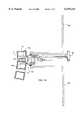
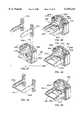
- FIG. 1is a front perspective view of the milling block of the present invention.
- FIG. 2is a rear perspective view of the milling block of the present invention.
- FIG. 3is a front elevation view of the milling block of the present invention.
- FIG. 4is a top plan view of the milling block of the present invention.
- FIG. 5is a side elevational view of the milling block of the present invention.
- FIG. 6is a partial sectional view of the milling block of the present invention showing the sliding instrument guide within the milling block.
- FIG. 7Ais a side perspective view of a pin driving instrument and a pin used to secure the milling block of the present invention to a segment of the spine.
- FIG. 7Bis a top plan view of a pin used to secure the milling block of the present invention to the vertebrae.
- FIG. 8is a front perspective view of a handle used to hold the milling block of the present invention.
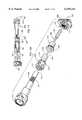
- FIG. 9is an exploded view of a distractor and distractor holder of the present invention with the distractor shown about to be inserted into the milling block of the present invention.
- FIG. 10is an exploded perspective view of the distractor holder of the present invention.
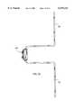
- FIG. 11Ais an exploded view of the distractor holder, the distractor and the calibration gauge of the present invention.
- FIG. 11Bis a side elevational view of the distractor of the present invention having a insertion end for placing two adjacent vertebrae in parallel relationship to each other.
- FIG. 11Cis a side elevational view of the distractor of the present invention having a converging insertion end for placing two adjacent vertebrae in angular relationship to each other such as lordosis.
- FIG. 11Dis a side elevational view of a segment of the spine with two distractors of the present invention placed at two adjacent disc levels illustrating the creation of lordosis with one distractor and the parallel spacing of the vertebrae by the other distractor.
- FIG. 12is a partial cut away of a front elevational view of the calibration gauge of the present invention with the distractor inserted therein and the distractor holder coupled to the distractor insertion end of the calibration gauge.
- FIG. 13is a side elevational view of the milling block of the present invention placed against the anterior aspect of a segment of the spine with the distractor holder coupled to the milling block and the distractor inserted in the disc space between two adjacent vertebrae and the handles attached to the milling block of the present invention.
- FIG. 14is a side elevational view of the segment of the spine with the milling block of the present invention attached to the anterior aspect of the spine by a plurality of pins shown partially in hidden line and being driven by a pin driver.
- FIG. 15is a side elevational view of a segment of the spine with the milling block of the present invention engaged to two adjacent vertebrae by a plurality of pins shown partially in hidden line.
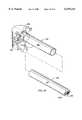
- FIG. 16is an exploded perspective view of the bone removal assembly and calibration gauge of the present invention.
- FIG. 17is a partial cut-away of a front elevational view of the calibration gauge of the present invention with the bone removal assembly inserted therein to adjust the depth of the milling bit.
- FIG. 18Ais an exploded perspective view of the bane removal assembly of the present invention about to be inserted into the milling block of the present invention.
- FIG. 18Bis an exploded side elevational view of the bone removal assembly being inserted into the milling block of the present invention shown engaged to a segment of the spinal column.
- FIG. 19is a side perspective view of the bone removal assembly coupled to a milling block of the present invention that is engaged to a segment of the spinal column by a plurality of pins shown partially in hidden line.
- FIG. 20is a side elevational view of a segment of the spinal column having an implant inserted in the space created across the disc space and into the adjacent vertebrae with the milling block instrumentation and method of the present invention.
- FIG. 21is a front elevational view of a segment of the spine having an implant with flat side walls from top to bottom inserted in the space created across the disc space and into the adjacent vertebrae with the milling block instrumentation and method of the present invention.
- FIG. 22is a sectional view of a vertebra taken along line 22--22 of FIG. 21 illustrating the space created into the vertebrae by the milling block instrumentation and method of the present invention.
- FIG. 23is a front elevational view of a segment of the spinal column having an implant with curved side walls from top to bottom inserted into the space created across the disc space and into the adjacent vertebrae by the milling block and instrumentation of the present invention.
- FIG. 24is a side elevational view of a segment of the spinal column showing an implant inserted between two adjacent vertebrae with the methods and instrumentation of the prior art.
- FIG. 25is a front elevational view an implant inserted between two adjacent vertebrae with the methods and instrumentation of the prior art.
- FIG. 26is a sectional view along lines 26--26 of FIG. 25 illustrating the space created in the vertebrae by the methods and instrumentation of the prior art.
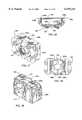
- FIG. 27is a rear perspective view of an alternative embodiment of the milling block of the present invention.
- FIG. 28is a front perspective view of the alternative embodiment of the milling block of the present invention shown in FIG. 27.
- FIG. 29is a front elevational view of the alternative embodiment of the milling block of the present invention shown in FIG. 27.
- FIG. 30is a top plan view of an alternative embodiment of the alternative embodiment of the milling block of the present invention shown in FIG. 27.
- FIG. 31is a side elevational view of the alternative embodiment of the milling block of the present invention shown in FIG. 27.
- FIG. 32is a side sectional view of the alternative embodiment of the milling block of the present invention shown in FIG. 27 with a distractor element inserted into the milling block.
- FIG. 33is a side perspective view of the alternative embodiment of the distractor element of the milling block of the present invention.
- FIG. 34is a side perspective view of an alternative embodiment of the handle used to hold the milling block of the present invention.
- FIG. 35is a side elevational view of the alternative embodiment of the milling block of FIG. 27 with a pair of detachable handles shown attached to the milling block.
- FIG. 36is an exploded perspective view of an alternative embodiment of the bone removal assembly and the milling block of the present invention shown in FIG. 27.
- FIG. 37is a perspective view of the adapter sleeve of the bone removal assembly of the present invention shown in FIG. 36.
- FIG. 38is a front elevational view of an alternative embodiment of the milling block of the present invention.
- FIG. 39is a rear elevational view of the alternative embodiment of the milling block of the present invention shown in FIG. 38.
- FIG. 40is a top plan view of the alternative embodiment of the milling block of the present invention shown in FIG. 38.
- FIG. 41is a side elevational view of the alternative embodiment of the milling block of the present invention shown in FIG. 38.
- FIG. 42is a sectional view along lines 42--42 of FIG. 39 of the milling block of the present invention having a bone removal member inserted therein for milling a space between two adjacent vertebrae.
- FIG. 43is a rear elevational view of an alternative embodiment of the milling block of the present invention with two adjacent vertebrae shown in hidden line.
- FIG. 44is a rear elevational view of an alternative embodiment of the milling block of the present invention with two adjacent vertebrae shown in hidden line.
- FIG. 45is a anterior elevational view of a segment of the spinal column illustrating the space created with the milling block of FIG. 44 and an artificial disc implanted within the created space.
- FIG. 46is a front perspective view of an alternative embodiment of the milling block of the present invention with a pair of distractor elements in place.
- FIG. 47is a front perspective exploded view of the alternative embodiment of the milling block of FIG. 46 and a pair of distractor elements of the present invention.
- FIG. 48is a front perspective view of an alternative embodiment of the milling block of the present invention.
- FIG. 49is a side perspective view of a pair of distractor elements of the present invention shown joined together at their tips.
- FIG. 50is a front perspective view of an alternative embodiment of the milling block of the present invention.
- FIG. 51is an exploded rear perspective view of an the preferred embodiment of the milling block and distractor holder of the present invention for use in the cervical spine.
- FIG. 52is a front perspective view of the embodiment of the milling block shown in FIG. 51.
- FIG. 53is a front elevational view of the embodiment of the milling block shown in FIG. 51.
- FIG. 54is a side elevational view of the embodiment of the milling block shown in FIG. 51.
- FIG. 55is a top plan view of the embodiment of the milling block shown in FIG. 51.
- FIG. 56is a rear perspective fragmentary view of the embodiment of the milling block shown in FIG. 51.
- FIG. 57is a fragmentary view of the distractor holder along line 57 of FIG. 51.
- FIG. 58is a side perspective view of an embodiment of a combined calibration gauge and handle of the present invention.
- FIG. 59is a rear elevational view of an alternative embodiment of the milling block of the present invention with two adjacent vertebrae shown in hidden line.
- FIG. 60is a front elevational view of the alternative embodiment of the milling block shown in FIG. 59.
- FIG. 61is a side elevational view of a cutting instrument for use with the alternative embodiment of the milling block apparatus shown in FIG. 59.
- FIG. 62is a side perspective view of an alternative embodiment of the milling block apparatus of the present invention.
- FIG. 63is a sectional view along line 63--63 of FIG. 62 of the milling block apparatus of the present invention.
- FIG. 64is an exploded perspective view of a combined outer sleeve and distractor engaging two adjacent vertebrae and the milling block of FIG. 62 about to be inserted into the outer sleeve.
- FIG. 65is a side elevational view of the segment of the human spine with a milling instrument interposed between two adjacent vertebrae for preparing a disc space having anterior and posterior retaining walls for retaining an implant.
- FIG. 66is an exploded rear perspective view of an alternative embodiment of the milling block and bone removal assembly of the present invention.
- FIG. 67is a front perspective view of the distractor portion of the milling block of FIG. 66.
- FIG. 68is a side elevational view of an alternative embodiment of the milling block and bone removal assembly of the present invention shown engaging two adjacent vertebrae.
- FIG. 69is a rear elevational view of the milling block of FIG. 68.
- FIG. 70is a rear perspective view of the milling block of FIG. 68.
- FIG. 71is an elevational view along lines 71--71 of FIG. 68.
- FIG. 72is an elevational view along lines 72--72 of FIG. 68.
- the instrumentation of the present inventioncomprises a milling block, generally referred to by the numeral 100.
- the milling block 100has an overall generally rectangular configuration having a front face 102, an opposite rear face 104, a top side 106, a bottom side 108 and left and right sides 110 and 112, respectively.
- the front face 102comprises a surface having a concave configuration that conforms to the natural curvature of the anterior aspect of a segment of the human spinal column and permits the placement of the milling block 100 in close proximity to the anterior aspect of the spinal column.
- the milling block 100comprises a central aperture 114 through the center of the milling block 100.
- the aperture 114is preferably oblong-shaped, having an approximate width of 18-30 mm for use in the cervical spine, 30-50 mm for use in the lumbar spine, and if the milling block 100 is used on the left and right sides of the mid sagittal axis of a lumbar vertebrae separately, the approximate width of the aperture 114 is 15-25 mm and the approximate height of the aperture 114 is 5-20 mm.
- Located within the aperture 114is a sliding mill guide 116 having a threaded port 118 for engaging various instrumentation as discussed in detail below. The mill guide 116 slides in a transverse motion from side to side within the central aperture 114 along the transverse axis of the aperture 114.
- the milling block 100comprises a plurality of pin holes 120a-d which pass through the milling block 100 from the rear face 104 through the front face 102.
- the pin holes 120a-dhave a wider diameter entrance at the rear face 104 of the milling block 100 and have a narrower diameter passage at the front face 102 of the milling block 100.
- the wide diameter entrance of the pin holes 120a-dpermit the countersinking of the head portion 126 of pin 128 illustrated in FIGS. 7A and 7B and described in detail below.
- the rear face 104 of the milling block 100includes blind holes 130 and 132 centrally positioned and located between the pin holes 120a-b and 120c-d, respectively.
- the blind holes 130 and 132receive posts 134a and 134b of the distractor holder 158 illustrated in FIG. 9 and described in detail below.
- the top and bottom sides 106 and 108 of the milling block 100comprise tracks 136a and 136b having an inverted T-shaped configuration for engaging a T-shaped rail member 138 of the handles 140 and 142 illustrated in FIG. 8 and described in detail below.
- Each of the tracks 136a and 136bhave a depression 144 for engaging a detent means 146 on the handles 140 and 142 for centering the handles 140 and 142 relative to the milling block 100 and for locking the handles 140 and 142 in place once they are attached to the milling block 100.
- the handle 140is shown having a general L-shaped configuration with an inverted T-shaped rail member 138 for engaging the tracks 136a and 136b of the milling block 100.
- the handle 140has detent means 146 located in the center of the rail member 138 which fits into the depression 144 of the tracks 136a and 136b and functions to center and lock the handle 140 to the milling block 100.
- the distractor apparatus 150comprises a distractor 151 having a cylindrical shaft 152 with a bullet-shaped leading end 154.
- the distractor 151is interposed in the disc space between two adjacent vertebrae and bears upon the endplates of the adjacent vertebrae to urge the vertebrae apart.
- the leading end 154 of the distractor 151is a flattened member having a height that may correspond to the normal anatomic height of the disc space between two adjacent vertebrae in which the distractor 151 is to be inserted or may have a height that is less than the anatomic height of the disc space. It is appreciated that the distracted height of the disc space may be equal to, less or greater than the normal anatomic height of the disc space.
- the shaft 152 of the distractor 151has a plurality of annular slots 156 for engaging the distractor holder 158.
- the leading end 154 of the distractor 151may have a height in the range of 4 mm to 20 mm, with 10 mm to 14 mm being the preferred height in the lumbar spine except for a collapsed and degenerated disc which may be less, 5.5 mm to 7.5 mm being the preferred height in the cervical spine.
- the distractor 151may have a thickness in the range from 1 mm to as great as 20 mm in the cervical spine, with 2 mm being the preferred thickness. In the lumbar spine the distractor 151 may be from 2 mm to 50 mm thick with a range of 2 mm to 5 mm being preferred.
- the length of the portion of the leading end 154 distractor 151 extending beyond the front face 102 of the milling block 100is less than the depth of the disc space in that location.
- the "depth” of the disc spaceis the distance between the anterior and posterior aspect of a vertebrae; the “width” of the disc space is the distance between the lateral aspects of a vertebrae; and the “height” of the disc space is the distance between two vertebral endplates adjacent to the disc space.
- the length of distractor 151would range from 8 mm to 20 mm, with 10-15 mm being preferred as measured at the sagittal (left from right) midline; while in the lumbar spine the distractor 151 length would range from 15 mm to 40 mm, with 20 mm to 35 mm being preferred.
- the distractor holder 158has an inverted Y-configuration with a central tubular member 160 and a base member 160.
- the bottom portion 164 of the tubular member 160has side slots 166 having a width sufficient o accommodate the thickness of the leading end 154 of the distractor 151.
- Located over the bottom portion of the tubular member 160is a sleeve 168 which engages the bottom portion 164 and rotates freely about the bottom portion 164 of the tubular member 160.
- the sleeve 168has an external thread 170 for engaging the milling port 118 of the sliding mill guide 116 and knob 171 for rotating the sleeve 168.
- the sleeve 168engages the opening 186 in the drill insertion end 184 of the calibration gauge 180 illustrated in FIG. 11A and described in detail below.
- posts 134a and 134bfor centering and engaging the distractor holder 158 to the milling block 100 and to the distractor insertion end 182 of the calibration gauge 180.
- the posts 134a and 134bfit into the blind holes 130 and 132 of the milling block 100 and also fit into the blind holes 188a and 188b of the calibration gauge 180.
- the upper portion 172 of the tubular member 160 of the distractor holder 158has a spring loaded locking collar 174 for locking the distractor 151 to the distractor holder 158 after the distractor 151 is inserted into the distractor holder 158.
- the distractor holder 158holds the distractor 151 with a spring loaded gripping member 176 that is configured to engage the annular slots 156 in the shaft 152 of the distractor 151.
- the locking collar 174is locked and unlocked by the partial rotation of the locking collar 174 about the upper portion 170 of the tubular member 160.
- the locking collar 174is kept in a "locked” or "unlocked” position by slot 173 and pin 175.
- the locking collar 174forces the gripping member 176 into the annular slots 156 of the shaft 152 of the distractor 151 to hold the distractor 151 within the distractor holder 158.
- the gripping member 176has tynes 177 with an enlarged head portion 178 which has a complimentary configuration for fitting the annular slots 156 of the distractor 151.
- the gripping member 176is locked by sliding the locking collar 174 in a direction away from the base 162 such that the locking collar 174 slides over the gripping member 176 to compress the tynes 177 into the slots 156.
- the locking collar 174is rotated and slid in the direction toward the base 162 to release the tynes 177 as shown in FIG. 9.
- a calibration gauge 180is shown for setting the depth of the distractor 151 within the distractor holder 158 and for setting the depth of the milling instrument 200 in the coupling member 208 described in detail below.
- the calibration gauge 180has a substantially rectangular configuration with a distractor insertion end 182 and a drill insertion end 184.
- the distractor insertion end 182has an opening 186 of a sufficient diameter for receiving the leading end 154 of the distractor 151 and a portion of the sleeve 168 of the distractor holder 158.
- the distractor insertion end 182has two blind holes 188a and 188b for receiving the posts 134a and 134b of the distractor holder 158.
- the drill insertion end 184has an aperture 190 of a sufficient diameter for receiving and setting the depth of a milling instrument 200.
- FIGS. 11B and 11Da side elevational view of a distractor 151 having parallel top and bottom sides 153a and 153b is shown inserted in the disc space between adjacent vertebrae V 1 and V 2 .
- the distractor 151is used to place and keep the two adjacent vertebrae V 1 and V 2 in parallel spatial relationship when the distractor 151 is inserted in the disc space with the top and bottom sides 153a and 153b placed against the vertebral endplates of the adjacent vertebrae V 1 and V 2 .
- the distractor 151is placed between two adjacent vertebral V 1 and V 2 to orient and maintain the vertebrae in parallel relationship to each other.
- FIGS. 11C and 11Da side elevational view of distractor 151' is shown having top and bottom sides 153a' and 153b' in a converging angular relationship to each other.
- the distractor 151'is used to place and keep two adjacent vertebrae V 2 and V 3 in angular relationship to each other, such as where the restoration of lordosis is desired at a specific disc level of the spine.
- the distractor 151'is placed between two adjacent vertebrae V 2 and V 3 to orient and maintain the vertebrae in angular relationship to each other.
- the calibration gauge 180for calibrating the depth of the distractor 151 within the distractor holder 158 is shown.
- the calibrator gauge 180is hollow and has a window 192 with graduated marks 194 indicating the depth in which the distractor 151 being held by the distractor holder 158 will penetrate the disc space between two adjacent vertebrae when the distractor 151 is subsequently inserted into the disc space as described in detail below.
- the graduated marks 194range from 11 to 21 mm to represent the length of insertion of the distractor 151 which penetrates the disc space.
- the distractor 151is selected and inserted into the distractor holder 158 and remains in the unlocked position as shown in FIG. 12.
- the leading end 154 of the distractor 151is then placed within the aperture 186 of the calibration gauge 180 such that the leading end 154 of the distractor 151 becomes visible through the window 192.
- the desired depth of the distractor 151may be selected in reference to the graduated marks 194 by adjusting the distractor 151 in relation to the distractor holder 158 such that the desired amount of the distractor 151 extends within the calibration gauge 180.
- the depth adjustment of the distractor 151is accomplished by sliding the shaft 151 the distractor 151 up or down in relation to the distractor holder 158. Once the correct depth suitable for the disc space in which the distractor 151 is to be inserted has been selected for the distractor 151, the locking collar 174 on the distractor holder 158 is rotated and moved to compress the tynes 177 of the gripping member 176 into the annular slots 156 of the distractor 151 and the distractor 151 is held in fixed relationship to the distractor holder 158 at the desired depth.
- the annular slots 156are spaced apart a distance corresponding to each of the graduated marks 194 to facilitate the depth selection and adjustment of the distractor 151 within the distractor holder 158.
- each of the annular rings 156is numbered for length which can be read directly from the shaft 152 as the number appearing beyond the gripping member 176.
- the distractor holder 158 with the distractor 151 locked in placeis coupled to the milling block 100 such that the leading end 154 of the distractor 151 passes through the threaded port 118 of the mill guide 116.
- the posts 134a and 134b of the distractor holder 158are positioned within the blind holes 130 and 132 of the milling block 100 and the sleeve 168 of the distractor holder 158 is threadably coupled to the threaded collar port 118 of the milling block 100.
- the handles 140 and 142are engaged to the milling block 100 with the rail member 138 in the tracks 136a and 136b and the detent means 146 positioned within the depression 144 of the tracks 136a and 136b.
- the combined distractor apparatus 150 and milling block 100 assemblyis then brought to the fusion site of the spine S from the anterior aspect of the spine S and the leading end 154 of the distractor 151 is then introduced into the disc space D between two adjacent vertebrae V 1 and V 2 .
- the distractor 151may be introduced into the disc space D turned on its side (with the sides 153a and 153b parallel to the horizontal plane of the disc space D) so as to facilitate introduction of the distractor 151 into the disc space D and then turned 90 degrees position the sides 153a and 153b of the distractor 151 perpendicular to the horizontal plane of the disc space D to distract the vertebrae V 1 and V 2 .
- the distractor 151may be introduced with the sides 153a and 153b perpendicular to the horizontal plane of the disc space D, relying on the bullet-shaped leading edge 154 to distract the vertebrae V 1 and V 2 apart during insertion.
- the angular relationship of the two vertebrae V 1 and V 2 adjacent to the disc space Dwill then be determined by the shape of the distractor 151 as illustrated in FIG. 11D and previously described above.
- the front face 102 of the milling block 100is placed adjacent to the segment of the spine S in which the fusion or artificial disc implantation is being performed.
- the milling block 100is then secured to the anterior aspect of the spine S by engaging each of the adjacent vertebrae V 1 and V 2 by inserting pins 128a-d with a pin driver 196.
- the pins 128a-dare inserted into the pin holes 120a-d and pass through the milling block 100 and penetrate the bone of the vertebrae V 1 and V 2 to engage the milling block 100 to the spine S.
- the milling apparatus 200is a bone removal device used to mill (remove a portion of bone from) the endplates of the vertebrae V 1 and V 2 adjacent to the disc space D in which a spinal implant is to be inserted.
- the milling apparatus 200comprises a milling bit 202 having a shaft 204 terminating in a cutting portion 206 having a cutting end and a cutting perimeter for cutting bone.
- the shaft 204is configured to fit within a driver coupling member 208 for coupling the milling bit 202 to a driving device, well known in the art, such as motorized drill or gas driven turbine (not shown).
- the driver coupling member 208has a shaft receiving end 210 for receiving the shaft 204 of the milling bit 202, an annular segmented collar portion 212, and a driver coupling end 214 for coupling to a driving device.
- gas driven turbinesare known and are presently manufactured and sold by Midas Rex, Anspach, Zimmer, Inc. and others, all these units attach to a gas driven turbine and hold a burr, but lack any adjustable depth limiting means, such as the adjustable depth limiting means of the present invention so as to be able to be lockably engaged into a further apparatus such as is required in the present invention.
- a locking adapter 216functions to lock the milling bit 202 to the driver coupling member 208, to couple the milling bit 202 to the calibration gauge 180, and to couple the milling bit 202 to the port 118 of the mill guide 116 of the milling block 100.
- the locking adapter 216comprises a hollow tubular sleeve 218 and has a similar configuration to the locking collar 174 of the distractor holder 158 described above.
- the sleeve 218has a locking collar 220 and a spring-loaded gripping member 222 similar to the locking collar 174 and gripping member 176 described above.
- the locking adapter 216has a bottom portion 224 of the sleeve 218 for coupling to the drill insertion end 184 of the calibration gauge 180.
- An adaptor fitting 226is provided having a threaded portion 228 for engaging the threaded port 118 of the milling guide 116.
- the proper diameter milling bit 202corresponding to the space to be created between the adjacent vertebrae is adjusted with the calibration gauge 180 to select the appropriate maximum safe penetration depth into the disc space of the milling bit 202 to prevent unwanted over penetration into the disc space.
- the length of the milling bit 202 that is capable of extending through the milling block 100is adjusted in reference to the calibration marks 194 of the calibration gauge 180 and the milling bit 202 is then locked to the driver coupling member 208.
- the milling apparatus 200would be coupled to the calibration gauge 180 and the driver coupling member would be advanced toward the calibration gauge 180 until the tip of the cutting portion 206 is aligned with the graduated marks 194 corresponding to 15 mm.
- the locking adapter 216is then rotated and placed in the locked position with the gripping member 222 engaging the segment on the collar portion 212 corresponding to 15 mm.
- the segments of the collar portion 212 of the milling apparatus 200can include calibration marks corresponding to the depth of the milling bit 202 extending through and protruding from the milling block 100.
- the gripping member 222is set to engage the appropriate segment of the collar 212 corresponding to the desired depth.
- the annular slot 154 on the shaft 152 of the distractor 151may include calibration marks for setting the desired depth of the distractor 151 without the use of a calibration gauge 180.
- the milling apparatusmay comprise any suitable bone removal means such as, but not limited to, burrs, router bits, abraders, grinders, rasps, drills, graters, saws, oscillating cutters, vibrating cutters, reciprocating cutters, orbital cutters, rotating cutters and lasers.
- suitable bone removal meanssuch as, but not limited to, burrs, router bits, abraders, grinders, rasps, drills, graters, saws, oscillating cutters, vibrating cutters, reciprocating cutters, orbital cutters, rotating cutters and lasers.
- the milling apparatus 200is then inserted through the adaptor fitting 226 and is screwed to the port 118 of the milling block 100.
- the milling bit 202is then rotated at high speed as illustrated by arrow R in FIG. 19.
- the milling apparatus 200 rotating at high speedis moved in the direction illustrated by arrow A and the portions of the vertebrae V 1 and V 2 adjacent to the disc space are then milled to create a space for receiving an implant.
- the milling apparatus 200is removed from the milling block 100 and the prepared space may be irrigated and suctioned through the port 118 of milling block 100, or alternatively the entire milling assembly including the milling block 100 may first be removed and the space then irrigated and suctioned.
- the disc space Dis distracted utilizing conventional means and the appropriate implant or implants are then inserted into the newly prepared space.
- the space B created by the milling block 100is substantially rectangular in shape and extends across the width and length of the vertebrae V 1 and V 2 to create a large area of contact between the vertebrae V 1 and V 2 and the implant I, which may have a curved (from side to side) trailing end to conform to the curvature of the vertebrae.
- implant Ihas been shown to have the substantially rectangular configuration it is appreciated that the implant I" can have a modified configuration with curved side walls (e.g. left and right) as shown in FIG. 23.
- the space C created with the instrumentation and method of the prior artis shown with an implant I' inserted therein.
- the space B created with the instrumentation of the method of the present inventionis substantially greater than was possible with the instrumentation and methods of the past.
- the spinal implant I inserted in the space Bcan be substantially larger than implant I' and have a substantially greater surface area of contact with the vertebrae V 1 and V 2 providing greater stabilization to the segment of the spine S being fused.
- the implantcan not only engage the very strong bone of the vertebral body at the endplate located posteriorly (in the back) and laterally (to each side), but as shown in FIG. 20, the implant may be embedded into sockets in the posterolateral corners of the vertebrae (dark shaded areas shown in FIGS. 20-26) providing enhanced stability to the implant which is blocked from moving more posteriorly or to either side.
- the milling block 300has a similar configuration to the milling block 100 described above, and comprises a modified distractor element 351 for separating and orienting the adjacent vertebrae in the appropriate relationship to each other prior to milling the space in which an implant is to be inserted.
- the distractor element 351is inserted in an inverted T-shaped slot 301 in the front face 302 of the milling block. 300.
- the slot 301comprises a spring loaded detent means 303 which functions to hold the distractor member 351 in place once it is inserted within the slot 301.
- FIG. 33a perspective view of the distractor element 351 is shown having an inverted T-shaped rail member 353 which corresponds in configuration to the inverted T-shaped slot 301.
- the distractor element 351has an insertion end 355 that is tapered and bullet shaped to facilitate insertion into the disc space D between two adjacent vertebrae V 1 and V 2 .
- the distractor element 351is inserted into the slot 301 of the milling block 300 prior to attaching the milling block 300 to the segment of the spine S in which the fusion is desired.
- the distractor element 351has a biconcave configuration to conform to the curvature of the cutting end 206 of the milling bit 202 of the milling apparatus 200, as described above, such that the horizontal excursion of milling bit 202 on either side of the distractor element 351 is maximized when used to create a space in the adjacent vertebrae V 1 and V 2 . It is appreciated that the distractor element 351 may come in different lengths in order to accommodate for the different dimensions of the disc space between the two adjacent vertebrae in which the surgical procedure is to be performed.
- the track members 336a and 336bare located on the sides of the milling block 300 such that handles 340 and 342 may be attached to the milling block 300 as previously described herein.
- the track members 336a and 336beach have a detent means 343a and 343b, respectively, for holding the handles 340 and 342 as shown in FIG. 30.
- the milling apparatus 361comprises a coupling member 308 which is identical to coupling member 208 previously described.
- the milling apparatus 361includes a milling bit 365 with a cutting portion 367 and a shaft portion 369 that are similar to the milling bit 202 previously described.
- Milling bitssuch as 365 are known and commercially available.
- the element of milling bit 365 as well as the use of an element such as milling bit 365 with a coupling means such as coupling member 308are well known in the art.
- An adaptor sleeve 371is used to couple the coupling member 308 and the milling bit 365 to the port 318 of the milling block 300.
- the sleeve 371comes in a variety of lengths depending on the desired depth of the space to be created and functions to limit the excursion of the milling bit 365 into the milling block 300. The longer the sleeve 371, the less the excursion of the milling bit 365 into the disc space between two adjacent vertebrae in which the opening is desired to be created. Thus, the surgeon can predetermine the depth of the space being created by selecting the appropriate sleeve 371 length prior to performing the procedure.
- the milling block 400comprises a central template 401 for creating a space of any desired shape and as an example, the space to be created may be a substantially rectangular space corresponding to the shape of the rectangular template 401.
- the template 401has a track 407 passing through the milling block 400 from the rear face 404 to the front face 402 of the milling block 400.
- the track 407is configured to receive a suitable bone removal means such as a drill a router or a laser, and the like, to remove a portion of the bone of the adjacent vertebrae milling instrument 403 and serves as a guide for creating the desired space in the adjacent vertebrae with a suitable bone removal means including, but not limited to, a router, to remove a portion of the bone of the adjacent vertebrae.
- a suitable bone removal meansincluding, but not limited to, a router, to remove a portion of the bone of the adjacent vertebrae.
- the milling instrument 403is inserted into a collar 405 which fits into the track 407 and is retained in slidable relationship within the track 407 of the template 401 and functions to guide the travel of the milling instrument 403 within the track 407.
- the drilling instrument 403is then activated and moved within the confines of the track 407 to create the desired space in the vertebrae, which space can be of a shape corresponding to the shape of track 107 of the template 401. This is particularly useful for creating a shape, such as that shown in FIG. 45, which might be desirable for installing an artificial disc device 409 between two adjacent vertebrae.
- FIGS. 43 and 44alternative embodiments of the milling block 400 designated as 400' and 400" are shown engaging two adjacent vertebrae V 1 and V 2 shown in hidden line.
- Tracks 401' and 407"are configured to create a space such as shown in FIG. 44 for receiving an artificial implant or an artificial joint as shown in FIG. 45. It is appreciated that in addition to the foregoing configurations of the template 400, that other configurations are possible and contemplated to be part of the present invention.
- the milling block 500is similar in configuration to the milling block 300 previously described above and comprises a pair of removable distractor elements 551a and 551b which are inserted in complimentary inverted T-shaped slots 553a and 553b at opposite sides of the milling block 500.
- the distractor elements 551a and 551bare inserted in the disc space D and function to restore the height of the disc space D prior to the milling operation to create the desired space.
- the distractor elements 551a and 551bare oriented at the sides of the central aperture 514 and each have a concave surface facing the central aperture 514 to conform to the curvature of the milling instrument such as milling bit 206, used to create the space between the two adjacent vertebrae.
- the lateral placement of the distractor elements 551a and 551ballows for the full side-to-side motion of the milling guide 516 to permit the unimpeded milling and creation of the space and without the need for having to remove and reinsert the milling instrument in order to get around a centrally placed distractor element such as distractor element 351 shown in FIG. 32.
- FIGS. 48-49an alternative embodiment of the milling block assembly of the present invention is shown and generally referred to by the numeral 600.
- the milling block 600is substantially the same as the milling block 500 described above except that the pair of distractor elements 651a and 651b are joined at their distal ends by a cross bar 655.
- Cross bar 655serves as a depth limiting means to any debris and to keep the pair of distractor elements 651a and 651b together as a unit.
- an alternative embodiment of the milling block 600'is shown and generally referred to by the numeral 600'.
- the milling block 600'instead of utilizing pins 128a-128d to engage the vertebrae, a centrally placed prongs 603a and 603b to engage the milling block 600' to the adjacent vertebrae.
- the prongs 603a and 603bare an integral part of the milling block 600' or may also be removable, like pins 128a-d discussed above, as an example.
- the milling block 600may engage the adjacent vertebrae via the distractor elements 651a and 651b positioned within the disc space to secure the milling block 600 to the spine.
- the tension forces generated by the distraction of the disc space from the insertion of the distractor elements 651a and 651bengage the vertebrae to the distractor elements 651a and 651b and functions to hold the milling block 600 to the spine.
- the preferred embodiment of the milling block for use in the cervical spine of the present inventiongenerally referred to by the number 700 is shown.
- the milling block 700is shown with a distractor holder 758 which is capable of being coupled directly to the milling block 700.
- the distractor holder 758has a pair of rotating post members 734a 734b and foot portions 737a and 737b, respectively, and handle portions 774a and 774b, respectively.
- the rear surface 704 of the milling block 700comprises pin grooves 721a-721d for receiving pins, such as pins 128, previously described.
- the rear surface 704also includes post grooves 723a and 723b for receiving the post members 734a and 734b in which the foot portions 737a and 737b of the post members 734a and 734b engage the lips of the post grooves 723a and 723b to lock the distractor holder 758 to the milling block 700.
- the distractor holder 758comprises of a gripping portion 776, similar to gripping member 176 previously described, for engaging a distractor, such as distractor 150 previously described.
- the distractor holder 758is capable of locking the distractor 150 in the desired position in order to limit the excursion of the distractor end 154 into the disc space.
- FIG. 57a fragmentary perspective view of the post member 734a is shown having a spring loaded detent means 790.
- the detent means 790is seated in a recess 791 and is biased by spring 792, functions to lock the rotating post member 734a in place once engaged to the milling block 700.
- the desired length of the distractor 150is set by engaging the calibration gauge 780 having one end capable of receiving the distractor holder 758.
- the depth of the distractor 750is set according to the graduated marks 794 on the calibration gauge 780, or in the alternative as previously described by reference to the depth markings on the annular rings of the distractor.
- the distractor holder 758is locked onto the distractor 750 in the same manner described above.
- the distractor holder 758is then coupled to the milling block 700 with the sleeve 764 engaging the port 718 of the milling block 700.
- the post members 734a and 734bare then locked into place by rotating the handle portions 774a and 774b so that the foot portions 737a and 737b are engaging the post grooves 723a and 723b of the rear surface 704 of the milling block 700.
- the pinssuch as pins 128a-d, are inserted into the pin holes 721a-721d and the milling block 700 is engaged to the adjacent vertebrae.
- the calibration gauge 780has a receiving end 781 for engaging the shaft to the distractor 151 such that the distractor holder 758 and distractor can be manipulated with the calibration gauge 780 serving as a handle.
- the distractor 151has a flattened end portion 152 with a detent 155 as shown in FIG. 11A, to couple the distractor 151 to the calibration gauge 780.
- the preparation and creation of the space between the adjacent vertebrae with milling block 700is performed in the similar manner described above with a milling apparatus such as milling apparatus 200 described above and shown in FIG. 16.
- the milling block 800comprises of a template 801 having a narrow track 807 for receiving a bone removal device such as an oscillating blade 809 as shown in FIG. 61.
- the narrow track 807functions to support and guide the motion of the oscillating blade 809 in the selected path of the track 807. Therefore, the track 807 can function as both means for accessing the adjacent vertebrae V 1 and V 2 and as a guiding means for guiding a bone removal instrument.
- the oscillating blade 809is used to cut the desired space in the adjacent vertebrae along the track 807 of the template 801. As shown in FIG.
- the template 800is engaged to two adjacent vertebrae shown in hidden line.
- the milling block 801maintains the vertebrae V 1 and V 2 in the correct spatial relationship and the cutting of the bone is performed with the oscillating blade 809 to create the desired space.
- slotted cutting fixturesare known in the field of orthopedic surgery, their purpose is to resect the end of a long bone, and not a spinal vertebrae; and all examples known to this author work on but a single bone, do not attach to both of the bones that would from a joint and do not fix those bones in a desired spatial and angular relationship so as to create the optimal joint space and conformation.
- the saw housing 812lockably engages the saw blade 809 by screw 811 within slot 810, which coupling means allows the protruding portion of blade 809 to be adjusted for length.
- the milling block apparatus 900is suitable for use in procedures in which the surgeon's hand is at a point remote from the site of the spinal fusion, such as for use in endoscopic procedures, or for performing procedures on the posterior aspect of the spine on either side of the mid-sagittal axis of the vertebrae avoiding the spinal cord and other delicate structures present at the posterior aspect of the spine.
- the milling block apparatus 900comprises an elongated member such as a hollow tube 901 having a front end 902 and a rear end 904 with milling guides 916a and 916b at each of its ends 902 and 904 for guiding a milling apparatus for creating and preparing the space between the two adjacent vertebrae.
- a milling apparatuswould be similar to the milling bit 202 described above, and would have a shaft of sufficient length to span the distance between the milling guides 916a and 916b and have a cutting portion capable of passing through the ports 918a and 918b and extending into the disc space from the front end 902 of the milling block apparatus 900 for milling the bone of the adjacent vertebrae.
- the desired space for receiving an implantmay be created from a position remote from the spine such as would be useful for endoscopic spinal surgery.
- the milling block apparatus 900may be placed directly against the site of the spine in which the procedure is to be performed, with the front end 902 placed across the disc space and contacting the vertebrae adjacent to that disc space.
- the milling procedure for removing a portion of bone from the adjacent vertebrae to create a space for receiving an implantis performed with a bone removal means as discussed above for the other embodiments of the present invention.
- the milling block apparatus 900may be placed through a combination outer sleeve distractor 980 having a hollow sleeve portion 982 and having extensions members 984 and 986 extending from one end of the sleeve portion 982 for insertion into the disc space.
- the extension member 984 and 986function to distract the disc space to its normal height and to engage the combination outer sleeve distractor 980 to the spine.
- the combination outer sleeve distractor 980is capable of receiving and guiding the milling block apparatus 900 to the appropriate site in which the milling procedure is to be performed.
- the elongated tubular body 901 of milling block apparatus 900would in use pass through the combined outer sleeve distractor 980, which itself would engage the spine at or adjacent to the disc space to be milled and would itself extend from the spine to outside of the patient's body.
- Such a combined outer sleeve distractoris taught by Michelson in co-pending application Ser. No. 08/396,414 filed on Feb. 27, 1995, incorporated herein by reference.
- the bone removal from the adjacent vertebrae for creating the space for receiving an implantis performed with the milling block apparatus 900 positioned within the combination outer sleeve distractor 980 with a bone removal device passing through the ports 918a and 918b of the sliding mill guides 916a and 916b.
- the milling block 900 as here taughtneed not be cylindrical and can be any shape, for example, square or rectangular to conform to the shape of the combination outer sleeve distractor 980. Furthermore, any such extended milling block 900 may have a flange proximally (rear end) or threads, or other means to fix, its position relative to said outer sleeve.
- FIG. 65a side view of a segment of the human spine with two adjacent vertebrae having a milling apparatus 1000 having a shaft 1002 and a cutting portion 1004 for preparing a space for receiving an implant, in which both the anterior and posterior aspects of the adjacent vertebral endplates have bone retaining walls 1000a and 1000b, respectively.
- the anterior and posterior retaining wallsare created by the cutting portion 1004 having a larger diameter than the shaft 1002 of the milling apparatus 1000 and a length which fits within the depth of the adjacent vertebrae.
- Such a configurationpermits the placement of substantially rectangular implant within the prepared space.
- the retaining walls 1000a and 1000b in the anterior and posterior aspects of the endplatesfunction to lock and secure an implant or bone graft once installed between the two adjacent vertebrae.
- bone milling instrumentcapable of cutting both on its leading end and along its sides
- a variety of bone cutting or abrading instrumentsincluding a drill rasp, burr, abrander or even a saw blade edge of the oscillating type or other could be used.
- bone milling meansis shown as having a length extending at least as long as the depth of bone to be removed, the bone removal means can have a variety of shapes and lengths.
- the milling block 1100comprises two separable members: an instrument guiding member 1110 and a distractor base member 1112.
- the distractor base member 1112has a generally rectangular upper portion 1113 having a front face 1102 and a rear face 1104.
- the front face 1102has a concave configuration that conforms to the natural curvature of a segment of the human spinal column and permits the placement of the front face 1102 of the milling block 1100 in close proximity to the spinal column.
- the upper portion 1113 of the distractor base member 1112has a recess 1115 for receiving and holding a portion 1119 of the instrument guiding member 1110 of the milling block 1100 and a central opening 1117 through the center of upper portion 1113.
- the opening 1117is preferably oblong-shaped, having an approximate width of 18-30 mm for use in the cervical spine, 30-50 mm for use in the lumbar spine, and if the milling block 1100 is used on the left and right sides of the mid-sagittal axis of a lumbar vertebrae separately, the approximate width of the opening 1114 is 15-25 mm and the approximate height of the opening 1114 is 5-20 mm.
- Extending from the upper portion 1113 and extending beyond the front face 1102are a pair of distractor elements 1151a and 1151b similar in configuration to the distractor elements 651a and 651b previously described above.
- the distractor elements 1151a and 1151bare capable of being introduced into the disc space between two adjacent vertebrae to place the vertebrae in a selected spatial relationship. The insertion of the distractor elements 1151a and 1151b into the disc space also functions to engage the distractor base member 1112 to the adjacent vertebrae.
- the instrument guiding member 1110 of the milling block 1100has a leading surface 1162, a trailing surface 1160, and a central aperture 1114 through its center having a suitable configuration corresponding to the central opening 1117 of the distractor base member 1112.
- Located within the aperture 1114is a sliding mill guide 1116 having a threaded port 1118 for engaging various instrumentation as previously discussed in detail above.
- the mill guide 1116slides in a transverse motion from side to side within the central aperture 1114 along the transverse axis of the aperture 1114.
- the leading surface 1162 of the instrument guiding member 1110is capable of interfacing with the rear face 1104 of the distractor base member 1112 and at least portion 1119 of the instrument guiding member 1110 is capable of being seated within the recess 1115 of the distractor base member 1112.
- the milling block 1100provides the added advantages of allowing the removal of the instrument guiding member 1110 while the distractor base member 1112 remains engaged to the spine maintaining the disc space distracted with the adjacent vertebrae in the appropriate spatial relationship to each other. With the distractor base member 1112 still engaged to the spine, it is possible to introduce an implant through the central opening 1117 and into the space for receiving the implant that has been created across the disc space and into the adjacent vertebrae. After the implant has been inserted into the disc space, the distractor base member 1112 is removed and the implant remains in the space created with the milling apparatus of the present invention.
- the milling block 1200has a body member 1201 that is capable of extending across the disc space D and capable of engaging at least one of the vertebrae adjacent to the disc space D.
- the body member 1201has a front face 1202, an opposite rear face 1204 and a curved central portion 1205. It is appreciated that the central portion 1205 need not be curved.
- the front face 1202has a surface that permits the placement of the milling block 1200 against the vertebrae.
- the milling block 1200has a central aperture 1214 through the center of the body member 1201 for accessing the disc space D between two adjacent vertebrae.
- a sliding mill guide 1216Located within the aperture 1214 is a sliding mill guide 1216 having a groove 1217 for slideably engaging the body member 1201 to permit slideable movement of the mill guide 1216 relative to the body member 1201.
- the mill guide 1216has a central opening 1219 in communication with the central aperture 1214 and a sliding member 1221 within the central opening 1219 having a port 1218 for coupling the sliding member 1221 to an instrument such as a destractor previously described, or a bone removal device, such as milling apparatus 200 previously described. It is appreciated that the mill guide 1216 in addition to guiding a milling apparatus 200, is also capable of guiding other instruments into the disc space such as a distractor element used to align the vertebrae and to distract the disc space.
- the sliding member 1221 of the mill guide 1216is capable of transverse motion from one side to the other side of the central opening 1219 along the transverse axis of the opening 1219 to guide and control a bone removal device, such as milling apparatus 200, in a selected transverse path relative to the vertebrae adjacent to the disc space D to remove at least a portion of bone from the vertebrae.
- the mill guide 1216 of the milling block 1200is also capable of moving up and down in a vertical direction within the central aperture 1214 along the vertical axis of the aperture 1214, and along the curved central portion 1205 of the body member 1201.
- the vertical motion of the mill guide 1216guides and controls the milling apparatus 200 in a selected path that may be at an angle to the vertebrae in order to remove an angular portion of bone from the vertebrae.
- the angular orientation of the milling apparatus 1216 relative to the vertebraeis a result of the position of the mill guide 1216 along the curved central portion 1205 of the body member 1201. In this manner, an opening having an angular configuration may be created, and with an appropriate implant placed within the prepared opening, the normal anatomic lordotic relationship of the vertebrae adjacent to the disc space D may be restored.
- the vertebrae adjacent to the disc space Dcould be placed in angular relationship prior to the removal of at least a portion of bone from the vertebrae, or a frusto-conical shaped bone removal device could be employed.
- the milling block 1200has a plurality of screw holes 1220a-b which pass through the milling block 1200 from the rear face 1204 through the front face 1202.
- the screw holes 122a-breceive screws 1228a-b for engaging the milling block 1200 to the vertebrae adjacent to the disc space D.
- pins, pegs or other suitable means for attaching the milling block 1200 to the vertebrae adjacent to the disc space Dcould be utilized.
Landscapes
- Health & Medical Sciences (AREA)
- Life Sciences & Earth Sciences (AREA)
- Surgery (AREA)
- General Health & Medical Sciences (AREA)
- Veterinary Medicine (AREA)
- Biomedical Technology (AREA)
- Heart & Thoracic Surgery (AREA)
- Medical Informatics (AREA)
- Molecular Biology (AREA)
- Animal Behavior & Ethology (AREA)
- Nuclear Medicine, Radiotherapy & Molecular Imaging (AREA)
- Public Health (AREA)
- Engineering & Computer Science (AREA)
- Orthopedic Medicine & Surgery (AREA)
- Dentistry (AREA)
- Oral & Maxillofacial Surgery (AREA)
- Prostheses (AREA)
- Surgical Instruments (AREA)
- Orthopedics, Nursing, And Contraception (AREA)
- Magnetic Resonance Imaging Apparatus (AREA)
Abstract
Description
Claims (78)
Priority Applications (16)
| Application Number | Priority Date | Filing Date | Title |
|---|---|---|---|
| US08/688,758US6159214A (en) | 1996-07-31 | 1996-07-31 | Milling instrumentation and method for preparing a space between adjacent vertebral bodies |
| DE69739124TDE69739124D1 (en) | 1996-07-31 | 1997-07-31 | MILLING TOOL FOR THE PRODUCTION OF AN INTERVERTEBRAL ROOM |
| AT97935095TATE414476T1 (en) | 1996-07-31 | 1997-07-31 | MILLING TOOL FOR CREATING AN INTERVERTEBRAL SPACE |
| CA002446567ACA2446567C (en) | 1996-07-31 | 1997-07-31 | Milling instrumentation for preparing a space between adjacent vertebral bodies |
| CA002261654ACA2261654C (en) | 1996-07-31 | 1997-07-31 | Milling instrumentation and method for preparing a space between adjacent vertebral bodies |
| JP50896298AJP4002613B2 (en) | 1996-07-31 | 1997-07-31 | Milling device that secures space between adjacent vertebrae |
| CA002548800ACA2548800C (en) | 1996-07-31 | 1997-07-31 | Milling instrumentation having first and second tracks for preparing a space between adjacent vertebral bodies |
| AU38117/97AAU738161B2 (en) | 1996-07-31 | 1997-07-31 | Milling instrumentation and method for preparing a space between adjacent vertebral bodies |
| EP97935095AEP1006910B1 (en) | 1996-07-31 | 1997-07-31 | Milling instrumentation for preparing a space between adjacent vertebral bodies |
| PCT/US1997/012956WO1998004202A1 (en) | 1996-07-31 | 1997-07-31 | Milling instrumentation and method for preparing a space between adjacent vertebral bodies |
| ES97935095TES2317654T3 (en) | 1996-07-31 | 1997-07-31 | MILLING TOOL TO CREATE AN INTERVERTEBRAL SPACE. |
| US09/734,303US6440139B2 (en) | 1996-07-31 | 2000-12-12 | Milling instrumentation and method for preparing a space between adjacent vertebral bodies |
| US10/090,506US7083623B2 (en) | 1996-07-31 | 2002-02-27 | Milling instrumentation and method for preparing a space between adjacent vertebral bodies |
| US10/852,449US7635370B2 (en) | 1996-07-31 | 2004-05-24 | Bone removal device |
| US10/883,094US8066709B2 (en) | 1996-07-31 | 2004-07-01 | Distractor with opening |
| US13/173,116US8663232B2 (en) | 1996-07-31 | 2011-06-30 | Apparatus and method for creating an implantation space in a spine |
Applications Claiming Priority (1)
| Application Number | Priority Date | Filing Date | Title |
|---|---|---|---|
| US08/688,758US6159214A (en) | 1996-07-31 | 1996-07-31 | Milling instrumentation and method for preparing a space between adjacent vertebral bodies |
Related Child Applications (1)
| Application Number | Title | Priority Date | Filing Date |
|---|---|---|---|
| US09/734,303ContinuationUS6440139B2 (en) | 1996-07-31 | 2000-12-12 | Milling instrumentation and method for preparing a space between adjacent vertebral bodies |
Publications (1)
| Publication Number | Publication Date |
|---|---|
| US6159214Atrue US6159214A (en) | 2000-12-12 |
Family
ID=24765657
Family Applications (6)
| Application Number | Title | Priority Date | Filing Date |
|---|---|---|---|
| US08/688,758Expired - LifetimeUS6159214A (en) | 1996-07-31 | 1996-07-31 | Milling instrumentation and method for preparing a space between adjacent vertebral bodies |
| US09/734,303Expired - LifetimeUS6440139B2 (en) | 1996-07-31 | 2000-12-12 | Milling instrumentation and method for preparing a space between adjacent vertebral bodies |
| US10/090,506Expired - Fee RelatedUS7083623B2 (en) | 1996-07-31 | 2002-02-27 | Milling instrumentation and method for preparing a space between adjacent vertebral bodies |
| US10/852,449Expired - Fee RelatedUS7635370B2 (en) | 1996-07-31 | 2004-05-24 | Bone removal device |
| US10/883,094Expired - Fee RelatedUS8066709B2 (en) | 1996-07-31 | 2004-07-01 | Distractor with opening |
| US13/173,116Expired - Fee RelatedUS8663232B2 (en) | 1996-07-31 | 2011-06-30 | Apparatus and method for creating an implantation space in a spine |
Family Applications After (5)
| Application Number | Title | Priority Date | Filing Date |
|---|---|---|---|
| US09/734,303Expired - LifetimeUS6440139B2 (en) | 1996-07-31 | 2000-12-12 | Milling instrumentation and method for preparing a space between adjacent vertebral bodies |
| US10/090,506Expired - Fee RelatedUS7083623B2 (en) | 1996-07-31 | 2002-02-27 | Milling instrumentation and method for preparing a space between adjacent vertebral bodies |
| US10/852,449Expired - Fee RelatedUS7635370B2 (en) | 1996-07-31 | 2004-05-24 | Bone removal device |
| US10/883,094Expired - Fee RelatedUS8066709B2 (en) | 1996-07-31 | 2004-07-01 | Distractor with opening |
| US13/173,116Expired - Fee RelatedUS8663232B2 (en) | 1996-07-31 | 2011-06-30 | Apparatus and method for creating an implantation space in a spine |
Country Status (9)
| Country | Link |
|---|---|
| US (6) | US6159214A (en) |
| EP (1) | EP1006910B1 (en) |
| JP (1) | JP4002613B2 (en) |
| AT (1) | ATE414476T1 (en) |
| AU (1) | AU738161B2 (en) |
| CA (1) | CA2261654C (en) |
| DE (1) | DE69739124D1 (en) |
| ES (1) | ES2317654T3 (en) |
| WO (1) | WO1998004202A1 (en) |
Cited By (157)
| Publication number | Priority date | Publication date | Assignee | Title |
|---|---|---|---|---|
| WO1999063891A1 (en) | 1998-06-09 | 1999-12-16 | Michelson Gary K | Device for preparing a space between adjacent vertebrae to receive an insert |
| US20010010020A1 (en)* | 1999-03-05 | 2001-07-26 | Michelson Gary K. | Interbody spinal fusion implant having an anatomically conformed trailing end |
| US20020049444A1 (en)* | 1999-04-06 | 2002-04-25 | Knox Benjamin D. | Spinal fusion instrumentation system |
| WO2002058593A2 (en) | 2001-01-23 | 2002-08-01 | Michelson Gary K | Interbody spinal fusion implant with trailing end adapted to receive bone screws |
| WO2002067786A1 (en)* | 2001-02-21 | 2002-09-06 | Howmedica Osteonics Corp. | Instrumentation and method for intervertebral implant insertion |
| US20020156481A1 (en)* | 1998-04-09 | 2002-10-24 | Boyd Lawrence M. | Method and instrumentation for vertebral interbody fusion |
| US6482209B1 (en) | 2001-06-14 | 2002-11-19 | Gerard A. Engh | Apparatus and method for sculpting the surface of a joint |
| US20030023306A1 (en)* | 2000-03-14 | 2003-01-30 | Mingyan Liu | Vertebral implant for promoting arthrodesis of the spine |
| US20030032962A1 (en)* | 2000-02-22 | 2003-02-13 | Mcgahan Thomas V. | Instruments and techniques for disc space preparation |
| US20030032865A1 (en)* | 1998-04-09 | 2003-02-13 | Estes Bradley T. | Method and instrumentation for posterior interbody fusion |
| US20030040798A1 (en)* | 1995-06-07 | 2003-02-27 | Michelson Gary Karlin | Lordotic interbody spinal fusion implants |
| US20030097134A1 (en)* | 2001-11-16 | 2003-05-22 | Sdgi Holdings, Inc. | Bone removal device and method of use |
| US6572653B1 (en) | 2001-12-07 | 2003-06-03 | Rush E. Simonson | Vertebral implant adapted for posterior insertion |
| US6575981B1 (en) | 1999-02-04 | 2003-06-10 | Sdgi Holdings, Inc. | Methods and instrumentation for vertebral interbody fusion |
| US6582437B2 (en) | 1999-08-26 | 2003-06-24 | Sdgi Holdings, Inc. | Devices and methods for implanting fusion cages |
| US6610089B1 (en) | 1997-08-26 | 2003-08-26 | Sdgi Holdings, Inc. | Spinal implant and cutting tool preparation accessory for mounting the implant |
| EP1344493A1 (en)* | 2002-03-12 | 2003-09-17 | Waldemar Link (GmbH & Co.) | Instument set for insertion of intervertebral prostheses |
| US20030195517A1 (en)* | 1999-01-25 | 2003-10-16 | Michelson Gary K. | Instrumentation for creating an intervertebral space for receiving an implant |
| US6648895B2 (en) | 2000-02-04 | 2003-11-18 | Sdgi Holdings, Inc. | Methods and instrumentation for vertebral interbody fusion |
| US20040002712A1 (en)* | 2002-06-26 | 2004-01-01 | Alexander Grinberg | Endplate shaping device |
| WO2004002332A1 (en)* | 2002-06-28 | 2004-01-08 | Sdgi Holdings, Inc. | Instruments and techniques for spinal disc space preparation |
| US6682534B2 (en) | 2001-08-02 | 2004-01-27 | Depuy Acromed, Inc. | Endplate preparation instrument and associated method |
| US6723102B2 (en) | 2001-06-14 | 2004-04-20 | Alexandria Research Technologies, Llc | Apparatus and method for minimally invasive total joint replacement |
| US20040078079A1 (en)* | 2002-10-21 | 2004-04-22 | Foley Kevin T. | Systems and techniques for restoring and maintaining intervertebral anatomy |
| US20040087957A1 (en)* | 2001-11-16 | 2004-05-06 | Sdgi Holdings, Inc. | Bone removal device and method of use |
| US20040093084A1 (en)* | 2001-02-04 | 2004-05-13 | Michelson Gary K. | Method for inserting and deploying an expandable interbody spinal fusion implant |
| US6736821B2 (en) | 2002-06-18 | 2004-05-18 | Sdgi Holdings, Inc. | System and method of mating implants and vertebral bodies |
| US6743234B2 (en) | 1999-02-04 | 2004-06-01 | Sdgi Holdings, Inc. | Methods and instrumentation for vertebral interbody fusion |
| US6755839B2 (en) | 2002-06-19 | 2004-06-29 | Sdgi Holdings, Inc. | Adjustable surgical guide and method of treating vertebral members |
| US20040162563A1 (en)* | 2000-12-14 | 2004-08-19 | Michelson Gary K. | Spinal interspace shaper |
| US20040176764A1 (en)* | 2003-03-03 | 2004-09-09 | Centerpulse Spine-Tech, Inc. | Apparatus and method for spinal distraction using a flip-up portal |
| US20040177494A1 (en)* | 2002-03-12 | 2004-09-16 | Waldemar Link Gmbh & Co | Instrument set for fitting an intervertebral joint prosthesis |
| US20040215197A1 (en)* | 2003-04-24 | 2004-10-28 | Smith Maurice M. | Minimally invasive instruments and methods for preparing vertebral endplates |
| US20040249388A1 (en)* | 1996-07-31 | 2004-12-09 | Michelson Gary K. | Distractor with opening |
| US20050043740A1 (en)* | 2003-08-20 | 2005-02-24 | Haid Regis W. | Technique and instrumentation for preparation of vertebral members |
| US20050143731A1 (en)* | 2003-12-30 | 2005-06-30 | Medicinelodge, Inc. | Tibial condylar hemiplasty tissue preparation instruments and methods |
| US20050154331A1 (en)* | 2003-12-30 | 2005-07-14 | Christie Michael J. | Minimally invasive bone miller apparatus |
| US20050171605A1 (en)* | 2004-02-02 | 2005-08-04 | Cervitech, Inc. | Cervical prosthesis and instrument set |
| US20050171607A1 (en)* | 2000-06-13 | 2005-08-04 | Michelson Gary K. | Manufactured bone composite implant shaped to conform to a prepared implantation space |
| US20050203532A1 (en)* | 2004-03-12 | 2005-09-15 | Sdgi Holdings, Inc. | Technique and instrumentation for intervertebral prosthesis implantation using independent landmarks |
| US20050203533A1 (en)* | 2004-03-12 | 2005-09-15 | Sdgi Holdings, Inc. | Technique and instrumentation for intervertebral prosthesis implantation |
| US20050267578A1 (en)* | 2000-06-13 | 2005-12-01 | Michelson Gary K | Ratcheted bone dowel having smooth sides and method for use thereof |
| US20050288677A1 (en)* | 2005-10-03 | 2005-12-29 | Inventit, Llc | Spinal surgery distractor with an integrated retractor |
| US20060041313A1 (en)* | 2004-08-19 | 2006-02-23 | Sdgi Holdings, Inc. | Intervertebral disc system |
| US20060074432A1 (en)* | 2004-10-06 | 2006-04-06 | Depuy Spine, Inc. | Modular medical tool and connector |
| US20060089649A1 (en)* | 2004-10-26 | 2006-04-27 | Ullrich Peter F Jr | Surgical instruments and method of using same |
| US20060089652A1 (en)* | 2004-10-26 | 2006-04-27 | Concept Matrix, Llc | Working channel for minimally invasive spine surgery |
| US20060100633A1 (en)* | 1998-06-09 | 2006-05-11 | Michelson Gary K | Method for preparing a space in bone to receive an insert |
| US20060100634A1 (en)* | 2004-11-09 | 2006-05-11 | Sdgi Holdings, Inc. | Technique and instrumentation for measuring and preparing a vertebral body for device implantation using datum block |
| US20060217731A1 (en)* | 2005-03-28 | 2006-09-28 | Sdgi Holdings, Inc. | X-ray and fluoroscopic visualization slots |
| US7125425B2 (en) | 2002-10-21 | 2006-10-24 | Sdgi Holdings, Inc. | Systems and techniques for restoring and maintaining intervertebral anatomy |
| US7153303B2 (en) | 2002-06-19 | 2006-12-26 | Sdgi Holdings, Inc. | Guide and blade for contouring vertebral bodies |
| US20070016213A1 (en)* | 2000-12-29 | 2007-01-18 | Zimmer Inc. | Instrument system for preparing a disc space between adjacent vertebral bodies to receive a repair device |
| US20070106388A1 (en)* | 2000-07-10 | 2007-05-10 | Sdgi Holdings, Inc. | Flanged interbody spinal fusion implants |
| US20070106384A1 (en)* | 2003-04-21 | 2007-05-10 | Rsb Spine Llc | Implant subsidence control |
| US20070266580A1 (en)* | 2006-04-14 | 2007-11-22 | Waldemar Link Gmbh & Co. Kg | Tool and method for making a ventral opening in a vertebra |
| US20070270862A1 (en)* | 2006-03-30 | 2007-11-22 | Sdgi Holdings, Inc. | Instruments and methods for preparing an intervertebral space |
| US20070293949A1 (en)* | 2004-10-08 | 2007-12-20 | Salerni Anthony A | Interior connecting interbody cage insertional tools, methods and devices |
| US20080015694A1 (en)* | 2006-01-13 | 2008-01-17 | Clifford Tribus | Spine reduction and stabilization device |
| US20080177270A1 (en)* | 2006-10-16 | 2008-07-24 | Depuy Spine, Inc. | Automatic locking casper distractor |
| US20080234684A1 (en)* | 2007-02-08 | 2008-09-25 | Warsaw Orthopedic, Inc. | Instruments and techniques for guiding instruments to a spinal column |
| US20080300601A1 (en)* | 2007-05-31 | 2008-12-04 | Fabian Henry F | Spine surgery method and instrumentation |
| US7473256B2 (en) | 2003-10-23 | 2009-01-06 | Trans1 Inc. | Method and apparatus for spinal distraction |
| US20090018589A1 (en)* | 2007-07-13 | 2009-01-15 | Smisson Iii Hugh F | Bone Screw |
| US7488327B2 (en) | 2004-04-12 | 2009-02-10 | Synthes (U.S.A.) | Free hand drill guide |
| US20090182341A1 (en)* | 2002-03-12 | 2009-07-16 | Cervitech, Inc. | Instrument set for fitting an intervertebral jont prosthesis |
| USD599015S1 (en) | 2009-03-13 | 2009-08-25 | Orthopedic Development Corporation | Surgical dilator impactor |
| US7585326B2 (en) | 2004-08-06 | 2009-09-08 | Spinalmotion, Inc. | Methods and apparatus for intervertebral disc prosthesis insertion |
| US20090270873A1 (en)* | 2008-04-24 | 2009-10-29 | Fabian Henry F | Spine surgery method and inserter |
| US7611536B2 (en) | 2001-04-02 | 2009-11-03 | Warsaw Orthopedic, Inc. | Hemi-interbody spinal fusion implants manufactured from a major long bone ring |
| US7635389B2 (en) | 2006-01-30 | 2009-12-22 | Warsaw Orthopedic, Inc. | Posterior joint replacement device |
| US20100004657A1 (en)* | 2008-01-18 | 2010-01-07 | Spinecore, Inc. | Instruments and methods for inserting artificial intervertebral implants |
| US7731754B2 (en) | 2002-09-19 | 2010-06-08 | Spinalmotion, Inc. | Intervertebral prosthesis |
| US7736380B2 (en) | 2004-12-21 | 2010-06-15 | Rhausler, Inc. | Cervical plate system |
| US20100152793A1 (en)* | 2007-09-13 | 2010-06-17 | David Lowry | Transcorporeal spinal decompression and repair systems and related methods |
| US7771475B2 (en) | 2002-02-02 | 2010-08-10 | Warsaw Orthopedic, Inc. | Spinal implant having deployable bone engaging projections |
| US7776046B2 (en) | 1998-04-09 | 2010-08-17 | Warsaw Orthopedic, Inc. | Method and instrumentation for vertebral interbody fusion |
| US7811326B2 (en) | 2006-01-30 | 2010-10-12 | Warsaw Orthopedic Inc. | Posterior joint replacement device |
| US7867238B2 (en) | 2001-03-01 | 2011-01-11 | Warsaw Orthopedic, Inc. | Method for using dynamic lordotic guard |
| US7887595B1 (en)* | 2005-12-05 | 2011-02-15 | Nuvasive, Inc. | Methods and apparatus for spinal fusion |
| US7935149B2 (en) | 2001-04-02 | 2011-05-03 | Warsaw Orthopedic, Inc. | Spinal fusion implant with bone screws |
| US7955360B2 (en) | 2001-03-01 | 2011-06-07 | Warsaw Orthopedic, Inc. | Method for using dynamic lordotic guard with movable extensions for creating an implantation space posteriorly in the lumbar spine |
| US7963981B2 (en) | 2004-04-19 | 2011-06-21 | Globus Medical, Inc. | Bone fixation plate |
| US20110196373A1 (en)* | 2010-02-11 | 2011-08-11 | Warsaw Orthopedic, Inc. | Bone preparation device |
| US8002834B2 (en) | 2004-07-30 | 2011-08-23 | Spinalmotion, Inc. | Intervertebral prosthetic disc with metallic core |
| US8083797B2 (en) | 2005-02-04 | 2011-12-27 | Spinalmotion, Inc. | Intervertebral prosthetic disc with shock absorption |
| US8090428B2 (en) | 2003-01-31 | 2012-01-03 | Spinalmotion, Inc. | Spinal midline indicator |
| US8092538B2 (en) | 2003-05-27 | 2012-01-10 | Spinalmotion, Inc. | Intervertebral prosthetic disc |
| US8097034B2 (en) | 2000-02-04 | 2012-01-17 | Warsaw Orthopedic, Inc. | Expandable arcuate interbody spinal fusion implant with two expanders |
| US20120101505A1 (en)* | 2010-10-26 | 2012-04-26 | Zimmer, Inc. | Patellar resection instrument with variable depth guide |
| US8167882B2 (en) | 2008-09-30 | 2012-05-01 | Depuy Products, Inc. | Minimally invasive bone miller apparatus |
| US8206449B2 (en) | 2008-07-17 | 2012-06-26 | Spinalmotion, Inc. | Artificial intervertebral disc placement system |
| US8236034B2 (en) | 2004-04-19 | 2012-08-07 | Globus Medical, Inc. | Bone fixation plate |
| US8292957B2 (en) | 2000-04-19 | 2012-10-23 | Warsaw Orthopedic, Inc. | Bone hemi-lumbar arcuate interbody spinal fusion implant having an asymmetrical leading end |
| US20120271312A1 (en)* | 2011-04-21 | 2012-10-25 | Jansen David R | Spline oriented indexing guide |
| US8323320B2 (en) | 2007-09-13 | 2012-12-04 | Transcorp, Inc. | Transcorporeal spinal decompression and repair system and related method |
| US8323340B2 (en) | 2000-04-19 | 2012-12-04 | Warsaw Orthopedic, Inc. | Artificial hemi-lumbar interbody spinal implant having an asymmetrical leading end |
| US8343220B2 (en) | 1999-05-05 | 2013-01-01 | Warsaw Orthopedic, Inc. | Nested interbody spinal fusion implants |
| US8372150B2 (en) | 2004-01-09 | 2013-02-12 | Warsaw Orthpedic, Inc. | Spinal device and method |
| US8419799B2 (en) | 2003-06-25 | 2013-04-16 | Depuy Products, Inc. | Assembly tool for modular implants and associated method |
| US8425569B2 (en) | 2010-05-19 | 2013-04-23 | Transcorp, Inc. | Implantable vertebral frame systems and related methods for spinal repair |
| US8486147B2 (en) | 2006-04-12 | 2013-07-16 | Spinalmotion, Inc. | Posterior spinal device and method |
| US8506631B2 (en) | 2007-08-09 | 2013-08-13 | Spinalmotion, Inc. | Customized intervertebral prosthetic disc with shock absorption |
| US8597298B2 (en) | 2006-09-29 | 2013-12-03 | DePuy Synthes Products, LLC | Proximal reamer |
| US8685035B2 (en) | 2003-01-31 | 2014-04-01 | Spinalmotion, Inc. | Intervertebral prosthesis placement instrument |
| US8685036B2 (en) | 2003-06-25 | 2014-04-01 | Michael C. Jones | Assembly tool for modular implants and associated method |
| US8709054B2 (en) | 2007-08-07 | 2014-04-29 | Transcorp, Inc. | Implantable vertebral frame systems and related methods for spinal repair |
| US8728084B2 (en) | 2011-06-27 | 2014-05-20 | Biomet Sports Medicine, Llc | Apparatus for repairing bone defects |
| US8758441B2 (en) | 2007-10-22 | 2014-06-24 | Spinalmotion, Inc. | Vertebral body replacement and method for spanning a space formed upon removal of a vertebral body |
| US8764833B2 (en) | 2008-03-11 | 2014-07-01 | Spinalmotion, Inc. | Artificial intervertebral disc with lower height |
| US8777959B2 (en) | 2005-05-27 | 2014-07-15 | Spinecore, Inc. | Intervertebral disc and insertion methods therefor |
| US8790346B2 (en) | 2003-06-25 | 2014-07-29 | DePuy Synthes Products, LLC | Modular tapered reamer for bone preparation and associated method |
| USD711537S1 (en) | 2009-10-14 | 2014-08-19 | Nuvasive, Inc. | Intervertebral implant |
| US8845730B2 (en) | 2008-07-18 | 2014-09-30 | Simplify Medical, Inc. | Posterior prosthetic intervertebral disc |
| US8864832B2 (en) | 2007-06-20 | 2014-10-21 | Hh Spinal Llc | Posterior total joint replacement |
| US8870884B2 (en) | 2011-06-27 | 2014-10-28 | Biomet Sports Medicine, Llc | Method for repairing bone defects |
| US8888852B2 (en) | 2004-01-09 | 2014-11-18 | Hh Spinal Llc | Spinal athroplasty device and method |
| US8998919B2 (en) | 2003-06-25 | 2015-04-07 | DePuy Synthes Products, LLC | Assembly tool for modular implants, kit and associated method |
| US9011544B2 (en) | 2008-05-05 | 2015-04-21 | Simplify Medical, Inc. | Polyaryletherketone artificial intervertebral disc |
| US9034038B2 (en) | 2008-04-11 | 2015-05-19 | Spinalmotion, Inc. | Motion limiting insert for an artificial intervertebral disc |
| US9095452B2 (en) | 2010-09-01 | 2015-08-04 | DePuy Synthes Products, Inc. | Disassembly tool |
| US9101495B2 (en) | 2010-06-15 | 2015-08-11 | DePuy Synthes Products, Inc. | Spiral assembly tool |
| US9119601B2 (en) | 2007-10-31 | 2015-09-01 | DePuy Synthes Products, Inc. | Modular taper assembly device |
| US9220603B2 (en) | 2008-07-02 | 2015-12-29 | Simplify Medical, Inc. | Limited motion prosthetic intervertebral disc |
| US9254130B2 (en) | 2011-11-01 | 2016-02-09 | Hyun Bae | Blade anchor systems for bone fusion |
| US9271739B2 (en) | 2009-08-06 | 2016-03-01 | Depuy (Ireland) | Surgical instrument and system of surgical instruments |
| US9345584B2 (en) | 2000-02-04 | 2016-05-24 | Warsaw Orthopedic, Inc. | Expandable push-in orthopedic implant |
| US9402663B2 (en) | 2010-04-23 | 2016-08-02 | DePuy Synthes Products, Inc. | Minimally invasive instrument set, devices and related methods |
| US9480511B2 (en) | 2009-12-17 | 2016-11-01 | Engage Medical Holdings, Llc | Blade fixation for ankle fusion and arthroplasty |
| US9498262B2 (en) | 2006-04-11 | 2016-11-22 | DePuy Synthes Products, Inc. | Minimally invasive fixation system |
| US9504578B2 (en) | 2011-04-06 | 2016-11-29 | Depuy Synthes Products, Inc | Revision hip prosthesis having an implantable distal stem component |
| US9572589B2 (en) | 2012-07-10 | 2017-02-21 | Stryker European Holdings I, Llc | Drill guide |
| US9655741B2 (en) | 2003-05-27 | 2017-05-23 | Simplify Medical Pty Ltd | Prosthetic disc for intervertebral insertion |
| US9717545B2 (en) | 2007-10-30 | 2017-08-01 | DePuy Synthes Products, Inc. | Taper disengagement tool |
| US9808281B2 (en) | 2009-05-20 | 2017-11-07 | DePuy Synthes Products, Inc. | Patient-mounted retraction |
| US9814598B2 (en) | 2013-03-14 | 2017-11-14 | Quandary Medical, Llc | Spinal implants and implantation system |
| US9827109B2 (en)* | 1999-03-07 | 2017-11-28 | Nuvasive, Inc. | Methods and apparatus for performing spine surgery |
| US9925051B2 (en) | 2010-12-16 | 2018-03-27 | Engage Medical Holdings, Llc | Arthroplasty systems and methods |
| US10098666B2 (en) | 2011-05-27 | 2018-10-16 | DePuy Synthes Products, Inc. | Minimally invasive spinal fixation system including vertebral alignment features |
| CN108992133A (en)* | 2018-08-21 | 2018-12-14 | 王鹏 | A kind of visualization bone milling cutter |
| US10238382B2 (en) | 2012-03-26 | 2019-03-26 | Engage Medical Holdings, Llc | Blade anchor for foot and ankle |
| US10390955B2 (en) | 2016-09-22 | 2019-08-27 | Engage Medical Holdings, Llc | Bone implants |
| USD858769S1 (en) | 2014-11-20 | 2019-09-03 | Nuvasive, Inc. | Intervertebral implant |
| US20190290445A1 (en)* | 2007-09-13 | 2019-09-26 | Globus Medical, Inc. | Transcorporeal spinal decompression and repair systems and related methods |
| US10456272B2 (en) | 2017-03-03 | 2019-10-29 | Engage Uni Llc | Unicompartmental knee arthroplasty |
| US11540928B2 (en) | 2017-03-03 | 2023-01-03 | Engage Uni Llc | Unicompartmental knee arthroplasty |
| US20230380930A1 (en)* | 2022-05-27 | 2023-11-30 | Chaeheon HEO | Milling bur for implant and method for forming implant hole using the same |
| US11883303B2 (en) | 2019-12-30 | 2024-01-30 | Vertebration, Inc. | Spine surgery method and instrumentation |
| US11890202B2 (en) | 2007-06-20 | 2024-02-06 | 3Spine, Inc. | Spinal osteotomy |
| US11925359B2 (en) | 2021-01-29 | 2024-03-12 | Zimmer, Inc. | Rotary electric surgical hammer impact tool |
| US12004793B2 (en) | 2021-02-26 | 2024-06-11 | Zimmer, Inc. | Bi-Spring surgical hammer impact tools |
| US12064158B2 (en) | 2021-01-29 | 2024-08-20 | Zimmer, Inc. | Orthopedic impactor tool |
| US12070256B2 (en) | 2020-11-10 | 2024-08-27 | Zimmer, Inc. | Bi-spring surgical impact tool |
| US12251148B2 (en) | 2021-02-01 | 2025-03-18 | Zimmer, Inc. | Tri-roll thread electric surgical impact tool |
| US12390259B2 (en) | 2022-07-19 | 2025-08-19 | Zimmer, Inc. | Linear electric surgical hammer impact tool |
| US12409046B2 (en) | 2022-04-12 | 2025-09-09 | 3Spine, Inc. | Total spinal joint systems with motion moderators |
| US12440248B2 (en) | 2022-06-28 | 2025-10-14 | DePuy Synthes Products, Inc. | Minimally invasive instrument set, devices, and related methods |
Families Citing this family (202)
| Publication number | Priority date | Publication date | Assignee | Title |
|---|---|---|---|---|
| US20080039859A1 (en) | 1997-01-02 | 2008-02-14 | Zucherman James F | Spine distraction implant and method |
| US7331963B2 (en)* | 1997-10-06 | 2008-02-19 | Warsaw Orthopedic, Inc. | Drill head for use in placing an intervertebral disc device |
| ATE274844T1 (en) | 1998-04-09 | 2004-09-15 | Sdgi Holdings Inc | VERTEBRATE BODY DISTRACTOR |
| DE29814174U1 (en) | 1998-08-07 | 1999-12-16 | Howmedica GmbH, 24232 Schönkirchen | Instruments for inserting an implant into the human spine |
| US6228022B1 (en) | 1998-10-28 | 2001-05-08 | Sdgi Holdings, Inc. | Methods and instruments for spinal surgery |
| US20050273111A1 (en)* | 1999-10-08 | 2005-12-08 | Ferree Bret A | Methods and apparatus for intervertebral disc removal and endplate preparation |
| EP1221914B1 (en)* | 1999-10-19 | 2003-09-03 | SDGI Holdings, Inc. | Cutting tool preparation accessory for mounting the implant |
| US6500180B1 (en)* | 1999-10-20 | 2002-12-31 | Sdgi Holdings, Inc. | Methods and instrumentation for distraction of a disc space |
| US6575899B1 (en) | 1999-10-20 | 2003-06-10 | Sdgi Holdings, Inc. | Methods and instruments for endoscopic interbody surgical techniques |
| US6461359B1 (en) | 1999-11-10 | 2002-10-08 | Clifford Tribus | Spine stabilization device |
| DE10003967A1 (en)* | 2000-01-25 | 2001-08-09 | Biomet Merck Deutschland Gmbh | Guide device |
| US6514260B1 (en) | 2000-03-15 | 2003-02-04 | Sdgi Holdings, Inc. | Methods and instruments for laparoscopic spinal surgery |
| USD493225S1 (en) | 2000-06-12 | 2004-07-20 | Ortho Development Corporation | Implant |
| US6579318B2 (en) | 2000-06-12 | 2003-06-17 | Ortho Development Corporation | Intervertebral spacer |
| JP4301944B2 (en)* | 2001-08-31 | 2009-07-22 | ウォーソー・オーソペディック・インコーポレーテッド | Intervertebral body fusion method and instrument |
| WO2003043505A1 (en)* | 2001-11-19 | 2003-05-30 | Osteotech, Inc. | Methods and instrumentation for disc space distraction |
| AU2003215099A1 (en)* | 2002-02-07 | 2003-09-02 | Ebi, L.P. | Anterior spinal implant |
| EP1482877B1 (en)* | 2002-03-11 | 2007-05-30 | Spinal Concepts Inc. | Instrumentation for implanting spinal implant devices |
| US8038713B2 (en) | 2002-04-23 | 2011-10-18 | Spinecore, Inc. | Two-component artificial disc replacements |
| US20080027548A9 (en) | 2002-04-12 | 2008-01-31 | Ferree Bret A | Spacerless artificial disc replacements |
| AU2003234508A1 (en)* | 2002-05-06 | 2003-11-17 | Warsaw Orthopedic, Inc. | Instrumentation and methods for preparation of an intervertebral space |
| US20040158254A1 (en)* | 2003-02-12 | 2004-08-12 | Sdgi Holdings, Inc. | Instrument and method for milling a path into bone |
| US6908484B2 (en) | 2003-03-06 | 2005-06-21 | Spinecore, Inc. | Cervical disc replacement |
| US7491204B2 (en) | 2003-04-28 | 2009-02-17 | Spine Solutions, Inc. | Instruments and method for preparing an intervertebral space for receiving an artificial disc implant |
| US20050021040A1 (en)* | 2003-07-21 | 2005-01-27 | Rudolf Bertagnoli | Vertebral retainer-distracter and method of using same |
| US7794465B2 (en)* | 2003-09-10 | 2010-09-14 | Warsaw Orthopedic, Inc. | Artificial spinal discs and associated implantation instruments and methods |
| EP1514518A1 (en)* | 2003-09-11 | 2005-03-16 | SDGI Holdings, Inc. | Impulsive percussion instruments for endplate preparation |
| US20050171550A1 (en)* | 2004-01-30 | 2005-08-04 | Sdgi Holdings, Inc. | Anatomic implants designed to minimize instruments and surgical techniques |
| US20050251261A1 (en)* | 2004-05-05 | 2005-11-10 | Sdgi Holdings, Inc. | Artificial intervertebral disc for lateral insertion |
| US8852195B2 (en) | 2004-07-09 | 2014-10-07 | Zimmer, Inc. | Guide templates for surgical implants and related methods |
| US7806898B2 (en) | 2004-07-09 | 2010-10-05 | Zimmer, Inc. | Modular guide systems and related rasps and methods for resecting a joint articulation surface |
| US20060025778A1 (en)* | 2004-07-21 | 2006-02-02 | Ferree Bret A | Methods and apparatus for artificial disc replacement (ADR) insertion and other surgical procedures |
| US20060106395A1 (en)* | 2004-07-23 | 2006-05-18 | Cervitech, Inc. | Instrument set and method for working a cervical vertebral body |
| US8470004B2 (en) | 2004-08-09 | 2013-06-25 | Si-Bone Inc. | Apparatus, systems, and methods for stabilizing a spondylolisthesis |
| US9949843B2 (en) | 2004-08-09 | 2018-04-24 | Si-Bone Inc. | Apparatus, systems, and methods for the fixation or fusion of bone |
| US8425570B2 (en) | 2004-08-09 | 2013-04-23 | Si-Bone Inc. | Apparatus, systems, and methods for achieving anterior lumbar interbody fusion |
| US20180228621A1 (en) | 2004-08-09 | 2018-08-16 | Mark A. Reiley | Apparatus, systems, and methods for the fixation or fusion of bone |
| US20070156241A1 (en) | 2004-08-09 | 2007-07-05 | Reiley Mark A | Systems and methods for the fixation or fusion of bone |
| US8414648B2 (en) | 2004-08-09 | 2013-04-09 | Si-Bone Inc. | Apparatus, systems, and methods for achieving trans-iliac lumbar fusion |
| US8444693B2 (en) | 2004-08-09 | 2013-05-21 | Si-Bone Inc. | Apparatus, systems, and methods for achieving lumbar facet fusion |
| US8388667B2 (en) | 2004-08-09 | 2013-03-05 | Si-Bone, Inc. | Systems and methods for the fixation or fusion of bone using compressive implants |
| US20060036251A1 (en) | 2004-08-09 | 2006-02-16 | Reiley Mark A | Systems and methods for the fixation or fusion of bone |
| US9662158B2 (en) | 2004-08-09 | 2017-05-30 | Si-Bone Inc. | Systems and methods for the fixation or fusion of bone at or near a sacroiliac joint |
| US8236029B2 (en) | 2004-08-11 | 2012-08-07 | Nlt Spine Ltd. | Devices for introduction into a body via a substantially straight conduit to for a predefined curved configuration, and methods employing such devices |
| US7575600B2 (en) | 2004-09-29 | 2009-08-18 | Kyphon Sarl | Artificial vertebral disk replacement implant with translating articulation contact surface and method |
| US8298235B2 (en)* | 2004-09-30 | 2012-10-30 | Depuy Spine, Inc. | Instrument and method for the insertion and alignment of an intervertebral implant |
| US8721722B2 (en) | 2004-10-18 | 2014-05-13 | Ebi, Llc | Intervertebral implant and associated method |
| US20060085077A1 (en)* | 2004-10-18 | 2006-04-20 | Ebi, L.P. | Intervertebral implant and associated method |
| WO2006058221A2 (en) | 2004-11-24 | 2006-06-01 | Abdou Samy M | Devices and methods for inter-vertebral orthopedic device placement |
| US20060247778A1 (en)* | 2005-01-26 | 2006-11-02 | Ferree Bret A | Intradiscal devices including spacers facilitating posterior-lateral and other insertion approaches |
| US20060189989A1 (en)* | 2005-02-10 | 2006-08-24 | Bert Jeffrey K | Zero profile template for installation of surgical plate |
| US8096995B2 (en) | 2005-02-17 | 2012-01-17 | Kyphon Sarl | Percutaneous spinal implants and methods |
| US7998208B2 (en) | 2005-02-17 | 2011-08-16 | Kyphon Sarl | Percutaneous spinal implants and methods |
| US8034080B2 (en) | 2005-02-17 | 2011-10-11 | Kyphon Sarl | Percutaneous spinal implants and methods |
| US7316690B2 (en) | 2005-02-17 | 2008-01-08 | Symmetry Medical, Inc. | Angled driver with depth gauge |
| US7927354B2 (en) | 2005-02-17 | 2011-04-19 | Kyphon Sarl | Percutaneous spinal implants and methods |
| US8029567B2 (en) | 2005-02-17 | 2011-10-04 | Kyphon Sarl | Percutaneous spinal implants and methods |
| US8096994B2 (en) | 2005-02-17 | 2012-01-17 | Kyphon Sarl | Percutaneous spinal implants and methods |
| US8092459B2 (en) | 2005-02-17 | 2012-01-10 | Kyphon Sarl | Percutaneous spinal implants and methods |
| US7993342B2 (en) | 2005-02-17 | 2011-08-09 | Kyphon Sarl | Percutaneous spinal implants and methods |
| US7431230B2 (en)* | 2005-03-16 | 2008-10-07 | Medtronic Ps Medical, Inc. | Apparatus and method for bone morselization for surgical grafting |
| US7695477B2 (en) | 2005-05-26 | 2010-04-13 | Zimmer, Inc. | Milling system and methods for resecting a joint articulation surface |
| SE528708C8 (en)* | 2005-06-01 | 2007-03-13 | Ortoviva Ab | Device for disk implants |
| US7727239B2 (en) | 2005-06-10 | 2010-06-01 | Zimmer Technology, Inc. | Milling system with guide paths and related methods for resecting a joint articulation surface |
| US8502681B2 (en)* | 2005-06-20 | 2013-08-06 | Biovigil, Llc | Hand cleanliness |
| US8657814B2 (en)* | 2005-08-22 | 2014-02-25 | Medtronic Ablation Frontiers Llc | User interface for tissue ablation system |
| US9072554B2 (en) | 2005-09-21 | 2015-07-07 | Children's Hospital Medical Center | Orthopedic implant |
| US8012214B2 (en) | 2005-09-27 | 2011-09-06 | Randall Lane Acker | Joint prosthesis |
| US12310602B2 (en) | 2005-09-27 | 2025-05-27 | Bioshift, Llc | Milling apparatus for implanting a joint prosthesis |
| US8034113B2 (en) | 2005-09-27 | 2011-10-11 | Randall Lane Acker | Joint prosthesis and method of implanting same |
| US9271843B2 (en) | 2005-09-27 | 2016-03-01 | Henry F. Fabian | Spine surgery method and implant |
| US8236058B2 (en) | 2005-09-27 | 2012-08-07 | Fabian Henry F | Spine surgery method and implant |
| US7717919B2 (en)* | 2005-11-04 | 2010-05-18 | Trans1 Inc. | Application of therapy aligned to an internal target path |
| DE102005056818A1 (en) | 2005-11-24 | 2007-05-31 | Aesculap Ag & Co. Kg | Guiding instrument for e.g. cutter, has guiding unit designed and arranged, such that cutting tool is guided along movement path defined by guiding unit and movement path corresponds to superimposed translation-rotatable-movement |
| US20070162040A1 (en)* | 2005-12-06 | 2007-07-12 | Zimmer Spine, Inc. | Spinal distraction and endplate preparation device and method |
| US20070173941A1 (en)* | 2006-01-25 | 2007-07-26 | Sdgi Holdings, Inc. | Intervertebral prosthetic disc and method of installing same |
| US20070213717A1 (en)* | 2006-02-14 | 2007-09-13 | Sdgi Holdings, Inc. | Biological fusion in the vertebral column |
| US7985246B2 (en) | 2006-03-31 | 2011-07-26 | Warsaw Orthopedic, Inc. | Methods and instruments for delivering interspinous process spacers |
| US7815681B2 (en)* | 2006-04-28 | 2010-10-19 | Warsaw Orthopedic, Inc. | Orthopedic support locating or centering feature and method |
| US7780676B2 (en) | 2006-07-11 | 2010-08-24 | Ebi, Llc | Intervertebral implantation apparatus |
| BRPI0714955A2 (en) | 2006-07-31 | 2013-07-23 | Systhes Gmbh | instrument system and method for preparing an intervertebral space to receive an implant, and milling guide for use with an instrument system |
| US20080046084A1 (en)* | 2006-08-21 | 2008-02-21 | John Sledge | Anterior cervical spine instrumentation and related surgical method |
| US8715350B2 (en)* | 2006-09-15 | 2014-05-06 | Pioneer Surgical Technology, Inc. | Systems and methods for securing an implant in intervertebral space |
| EP1923007A1 (en)* | 2006-11-16 | 2008-05-21 | Zimmer GmbH | Instrument |
| US7955392B2 (en) | 2006-12-14 | 2011-06-07 | Warsaw Orthopedic, Inc. | Interspinous process devices and methods |
| US20080161929A1 (en) | 2006-12-29 | 2008-07-03 | Mccormack Bruce | Cervical distraction device |
| EP2208481B1 (en) | 2007-07-27 | 2016-12-28 | R Tree Innovations, LLC | Inter-Body Implantation System |
| WO2009021144A2 (en)* | 2007-08-07 | 2009-02-12 | Transcorp, Inc. | Device for variably adjusting intervertebral distraction and lordosis |
| US7867263B2 (en)* | 2007-08-07 | 2011-01-11 | Transcorp, Inc. | Implantable bone plate system and related method for spinal repair |
| WO2009036360A1 (en)* | 2007-09-13 | 2009-03-19 | Transcorp, Inc. | Device and method for tissue retraction in spinal surgery |
| US20090088604A1 (en)* | 2007-09-28 | 2009-04-02 | David Lowry | Vertebrally-mounted tissue retractor and method for use in spinal surgery |
| EP2227181A1 (en) | 2007-11-27 | 2010-09-15 | Transcorp, Inc. | Methods and systems for repairing an intervertebral disc using a transcorporal approach |
| WO2009089367A2 (en) | 2008-01-09 | 2009-07-16 | Providence Medical Technology, Inc. | Methods and apparatus for accessing and treating the facet joint |
| US8361152B2 (en) | 2008-06-06 | 2013-01-29 | Providence Medical Technology, Inc. | Facet joint implants and delivery tools |
| CA2725811A1 (en) | 2008-06-06 | 2009-12-10 | Providence Medical Technology, Inc. | Facet joint implants and delivery tools |
| US9381049B2 (en) | 2008-06-06 | 2016-07-05 | Providence Medical Technology, Inc. | Composite spinal facet implant with textured surfaces |
| US9333086B2 (en) | 2008-06-06 | 2016-05-10 | Providence Medical Technology, Inc. | Spinal facet cage implant |
| EP2361046B1 (en) | 2008-06-06 | 2019-04-24 | Providence Medical Technology, Inc. | Cervical distraction/implant delivery device |
| US11224521B2 (en) | 2008-06-06 | 2022-01-18 | Providence Medical Technology, Inc. | Cervical distraction/implant delivery device |
| US8267966B2 (en) | 2008-06-06 | 2012-09-18 | Providence Medical Technology, Inc. | Facet joint implants and delivery tools |
| EP2337510B1 (en) | 2008-06-25 | 2018-10-31 | Stryker European Holdings I, LLC | Surgical instrumentation for implanting a prothesis |
| US8414592B2 (en)* | 2008-07-11 | 2013-04-09 | Q-Spine, Llc | Spinal measuring device and distractor |
| US8252001B2 (en)* | 2008-08-28 | 2012-08-28 | Q-Spine Llc | Apparatus and methods for inter-operative verification of appropriate spinal prosthesis size and placement |
| US8562608B2 (en) | 2008-09-19 | 2013-10-22 | Zimmer, Inc. | Patello-femoral milling system |
| US8911441B2 (en)* | 2008-10-03 | 2014-12-16 | Warsaw Orthopedic, Inc. | Endplate preparation instruments and methods of use |
| US9044280B1 (en)* | 2008-10-13 | 2015-06-02 | Nuvasive, Inc. | Surgical access system and related methods |
| US8114131B2 (en) | 2008-11-05 | 2012-02-14 | Kyphon Sarl | Extension limiting devices and methods of use for the spine |
| US8740911B2 (en)* | 2008-11-07 | 2014-06-03 | Howmedica Osteonics Corp. | Method of preparing a femur for implantation of a femoral implant |
| US8142440B2 (en)* | 2008-11-14 | 2012-03-27 | Warsaw Orthopedic, Inc. | Transverse centering tool with pin placement guides |
| US20100217268A1 (en)* | 2009-02-20 | 2010-08-26 | University Of Utah | Intervertebral milling instrument |
| US8257255B2 (en)* | 2009-02-24 | 2012-09-04 | Thompson Surgical Instruments, Inc. | Surgical retractor with locking blade |
| US9241798B2 (en)* | 2009-03-20 | 2016-01-26 | David A. Petersen | Surgical methods and tools |
| ES2563172T3 (en) | 2009-07-09 | 2016-03-11 | R Tree Innovations, Llc | Flexible intersomatic implant |
| EP2490598A1 (en)* | 2009-10-21 | 2012-08-29 | Thompson Surgical Instruments, Inc. | Retractor system for anterior cervical spine surgery |
| US10098674B2 (en) | 2009-10-22 | 2018-10-16 | Nuvasive, Inc. | System and method for posterior cervical fusion |
| US9204906B2 (en) | 2009-10-22 | 2015-12-08 | Nuvasive, Inc. | Posterior cervical fusion system and techniques |
| US8764806B2 (en) | 2009-12-07 | 2014-07-01 | Samy Abdou | Devices and methods for minimally invasive spinal stabilization and instrumentation |
| US8147526B2 (en) | 2010-02-26 | 2012-04-03 | Kyphon Sarl | Interspinous process spacer diagnostic parallel balloon catheter and methods of use |
| CN103096843A (en) | 2010-07-21 | 2013-05-08 | Nlt脊椎有限公司 | Spinal surgery implants and delivery system |
| EP2667798B1 (en) | 2011-01-28 | 2015-07-29 | Synthes GmbH | Reamer guide systems |
| WO2012135161A1 (en)* | 2011-03-28 | 2012-10-04 | Amendia Inc | A pedicle drill guide for spinal surgery |
| CN103648415A (en) | 2011-05-12 | 2014-03-19 | Nlt脊椎有限公司 | Tissue disruption device and corresponding methods |
| US8840667B1 (en) | 2011-06-16 | 2014-09-23 | Luis M Tumialán | Spinal plate system and related methods |
| US11000387B2 (en) | 2011-09-02 | 2021-05-11 | Episurf Ip-Management Ab | Implant for cartilage repair |
| EP2564792A1 (en)* | 2011-09-02 | 2013-03-06 | Episurf Medical AB | Modular surgical kit for cartilage repair |
| US10603049B2 (en) | 2011-09-02 | 2020-03-31 | Episurf Ip-Management Ab | Implant specific drill bit in surgical kit for cartilage repair |
| US8845728B1 (en) | 2011-09-23 | 2014-09-30 | Samy Abdou | Spinal fixation devices and methods of use |
| US9615856B2 (en) | 2011-11-01 | 2017-04-11 | Imds Llc | Sacroiliac fusion cage |
| US8998907B2 (en)* | 2011-11-23 | 2015-04-07 | Symmetry Medical Inc | System and method for a modular resection guide |
| US9463052B2 (en) | 2012-01-12 | 2016-10-11 | Integrity Implants Inc. | Access assembly for anterior and lateral spinal procedures |
| US8764757B1 (en) | 2012-01-31 | 2014-07-01 | Luis M. Tumialan | MIS TLIF systems and related methods |
| US8858559B2 (en) | 2012-02-06 | 2014-10-14 | Medtronic Ps Medical, Inc. | Saw blade stability and collet system mechanism |
| US8936597B2 (en) | 2012-02-06 | 2015-01-20 | Medtronic Ps Medical, Inc. | Deflectable finger connection feature on surgical saw blade |
| US20130226240A1 (en) | 2012-02-22 | 2013-08-29 | Samy Abdou | Spinous process fixation devices and methods of use |
| US8778026B2 (en) | 2012-03-09 | 2014-07-15 | Si-Bone Inc. | Artificial SI joint |
| US10363140B2 (en) | 2012-03-09 | 2019-07-30 | Si-Bone Inc. | Systems, device, and methods for joint fusion |
| US9044321B2 (en) | 2012-03-09 | 2015-06-02 | Si-Bone Inc. | Integrated implant |
| EP3818947B1 (en) | 2012-05-04 | 2023-08-30 | SI-Bone, Inc. | Fenestrated implant |
| US9198767B2 (en) | 2012-08-28 | 2015-12-01 | Samy Abdou | Devices and methods for spinal stabilization and instrumentation |
| US9320617B2 (en) | 2012-10-22 | 2016-04-26 | Cogent Spine, LLC | Devices and methods for spinal stabilization and instrumentation |
| USD732667S1 (en) | 2012-10-23 | 2015-06-23 | Providence Medical Technology, Inc. | Cage spinal implant |
| USD745156S1 (en) | 2012-10-23 | 2015-12-08 | Providence Medical Technology, Inc. | Spinal implant |
| EP2961337B1 (en)* | 2013-02-28 | 2021-04-28 | Feibel, Jonathan | Systems and apparatuses for reaming bone elements |
| WO2014145902A1 (en) | 2013-03-15 | 2014-09-18 | Si-Bone Inc. | Implants for spinal fixation or fusion |
| USD1010108S1 (en) | 2013-03-15 | 2024-01-02 | Medtronic, Inc. | Plunger |
| US9119732B2 (en) | 2013-03-15 | 2015-09-01 | Orthocision, Inc. | Method and implant system for sacroiliac joint fixation and fusion |
| US11311312B2 (en) | 2013-03-15 | 2022-04-26 | Medtronic, Inc. | Subcutaneous delivery tool |
| US9839448B2 (en) | 2013-10-15 | 2017-12-12 | Si-Bone Inc. | Implant placement |
| US11147688B2 (en) | 2013-10-15 | 2021-10-19 | Si-Bone Inc. | Implant placement |
| USD1032834S1 (en) | 2014-03-11 | 2024-06-25 | Medtronic, Inc. | Plunger |
| AU2015267055B2 (en) | 2014-05-27 | 2020-04-02 | Christopher U. Phan | Lateral mass fixation implant |
| JP2017520357A (en) | 2014-05-28 | 2017-07-27 | プロビデンス メディカル テクノロジー インコーポレイテッド | Outer mass fixing system |
| WO2016004991A1 (en) | 2014-07-09 | 2016-01-14 | Episurf Ip-Management Ab | Customized implant for cartilage repair and corresponding method of design |
| US20170172744A1 (en) | 2014-07-09 | 2017-06-22 | Episurf Ip-Management Ab | Surgical joint implant and a bone-mountable rig |
| JP6542362B2 (en) | 2014-09-18 | 2019-07-10 | エスアイ−ボーン・インコーポレイテッドSi−Bone, Inc. | Matrix implant |
| US10166033B2 (en) | 2014-09-18 | 2019-01-01 | Si-Bone Inc. | Implants for bone fixation or fusion |
| CN107530109B (en) | 2014-12-22 | 2020-07-28 | 比肯生物医学有限公司 | Sacroiliac joint fusion systems and methods |
| US10376206B2 (en) | 2015-04-01 | 2019-08-13 | Si-Bone Inc. | Neuromonitoring systems and methods for bone fixation or fusion procedures |
| CN105055056B (en)* | 2015-08-28 | 2017-03-29 | 四川大学华西医院 | Cervical vertebra uncinate vertebral joint fusion cage |
| US10058350B2 (en) | 2015-09-24 | 2018-08-28 | Integrity Implants, Inc. | Access assembly for anterior and lateral spinal procedures |
| CN108289689A (en) | 2015-10-13 | 2018-07-17 | 普罗维登斯医疗技术公司 | Joint of vertebral column implantation material conveying device and system |
| USD841165S1 (en) | 2015-10-13 | 2019-02-19 | Providence Medical Technology, Inc. | Cervical cage |
| US10857003B1 (en) | 2015-10-14 | 2020-12-08 | Samy Abdou | Devices and methods for vertebral stabilization |
| TW201806562A (en) | 2016-06-28 | 2018-03-01 | 普羅維登斯醫療科技公司 | Spinal implant and methods of using the same |
| USD887552S1 (en) | 2016-07-01 | 2020-06-16 | Providence Medical Technology, Inc. | Cervical cage |
| US10952686B2 (en) | 2016-08-02 | 2021-03-23 | Medtronic, Inc. | Mobile application to prompt physical action to measure physiologic response in implantable device |
| AU2017313725B2 (en) | 2016-08-15 | 2022-09-22 | Triqueue Holdings, Llc | Bone fusion device, system and methods |
| US10973648B1 (en) | 2016-10-25 | 2021-04-13 | Samy Abdou | Devices and methods for vertebral bone realignment |
| US10744000B1 (en) | 2016-10-25 | 2020-08-18 | Samy Abdou | Devices and methods for vertebral bone realignment |
| US10893855B2 (en) | 2017-03-27 | 2021-01-19 | Thompson Surgical Instruments, Inc. | Retractor system and retractor with detachable handle |
| US11871968B2 (en) | 2017-05-19 | 2024-01-16 | Providence Medical Technology, Inc. | Spinal fixation access and delivery system |
| US10603055B2 (en)* | 2017-09-15 | 2020-03-31 | Jcbd, Llc | Systems for and methods of preparing and fusing a sacroiliac joint |
| WO2019055173A1 (en) | 2017-09-18 | 2019-03-21 | Thompson Surgical Instruments, Inc. | Retractor system and side load connector for surgical retractor blade |
| US11013607B2 (en) | 2017-09-22 | 2021-05-25 | Encore Medical, L.P. | Talar ankle implant |
| US11116519B2 (en) | 2017-09-26 | 2021-09-14 | Si-Bone Inc. | Systems and methods for decorticating the sacroiliac joint |
| EP3501432A1 (en) | 2017-12-20 | 2019-06-26 | Stryker European Holdings I, LLC | Joint instrumentation |
| US11648128B2 (en) | 2018-01-04 | 2023-05-16 | Providence Medical Technology, Inc. | Facet screw and delivery device |
| ES3011907T3 (en) | 2018-03-28 | 2025-04-08 | Si Bone Inc | Threaded implants for use across bone segments |
| JP2021520247A (en) | 2018-04-03 | 2021-08-19 | コンバージェント デンタル, インコーポレイテッド | Laser system for surgical applications |
| WO2020061464A1 (en) | 2018-09-21 | 2020-03-26 | Providence Medical Technology, Inc. | Vertebral joint access and decortication devices and methods of using |
| US11179248B2 (en) | 2018-10-02 | 2021-11-23 | Samy Abdou | Devices and methods for spinal implantation |
| US11090068B2 (en)* | 2018-11-08 | 2021-08-17 | Ctl Medical Corporation | Vertebral body reaming method |
| EP4613244A2 (en) | 2019-02-14 | 2025-09-10 | SI-Bone Inc. | Implants for spinal fixation and or fusion |
| US11369419B2 (en) | 2019-02-14 | 2022-06-28 | Si-Bone Inc. | Implants for spinal fixation and or fusion |
| USD933230S1 (en) | 2019-04-15 | 2021-10-12 | Providence Medical Technology, Inc. | Cervical cage |
| USD911525S1 (en) | 2019-06-21 | 2021-02-23 | Providence Medical Technology, Inc. | Spinal cage |
| US11717186B2 (en) | 2019-08-27 | 2023-08-08 | Medtronic, Inc. | Body stability measurement |
| EP4027911A4 (en)* | 2019-09-12 | 2023-12-06 | Cartiva, Inc. | Bone cutting guides |
| EP4037618A4 (en)* | 2019-10-04 | 2023-12-13 | PTL Opco LLC | Allograft implant for fusing a sacroiliac joint |
| US11154402B1 (en)* | 2019-10-04 | 2021-10-26 | Pain TEQ, LLC | Instrumentation for fusing a sacroiliac joint |
| JP7646654B2 (en) | 2019-11-21 | 2025-03-17 | エスアイ-ボーン・インコーポレイテッド | Rod coupling assembly for bone stabilization construct - Patent application |
| AU2020392121B2 (en) | 2019-11-27 | 2025-05-22 | Si-Bone, Inc. | Bone stabilizing implants and methods of placement across SI joints |
| EP4072452A4 (en) | 2019-12-09 | 2023-12-20 | SI-Bone, Inc. | Sacro-iliac joint stabilizing implants and methods of implantation |
| US11375989B2 (en) | 2019-12-10 | 2022-07-05 | Thompson Surgical Instruments, Inc. | Retractor system, swivel lock, and surgical retractor blade |
| USD945621S1 (en) | 2020-02-27 | 2022-03-08 | Providence Medical Technology, Inc. | Spinal cage |
| USD945622S1 (en) | 2020-06-25 | 2022-03-08 | Medtronic, Inc. | Implantable medical device |
| USD1028227S1 (en) | 2020-07-06 | 2024-05-21 | Medtronic, Inc. | Handle for a medical tool |
| US11602313B2 (en) | 2020-07-28 | 2023-03-14 | Medtronic, Inc. | Determining a fall risk responsive to detecting body position movements |
| EP4259015A4 (en) | 2020-12-09 | 2024-09-11 | SI-Bone, Inc. | SACROILIAC JOINT STABILIZATION IMPLANTS AND METHODS OF IMPLANTATION |
| US11806002B2 (en) | 2021-02-01 | 2023-11-07 | Thompson Surgical Instruments, Inc. | Retractor system and retractor arm with detachable handle |
| US11931053B2 (en) | 2022-08-04 | 2024-03-19 | PTL Opco, LLC | Single-use joint decorticator apparatus |
| WO2025038769A1 (en) | 2023-08-15 | 2025-02-20 | Si-Bone Inc. | Pelvic stabilization implants, methods of use and manufacture |
Citations (5)
| Publication number | Priority date | Publication date | Assignee | Title |
|---|---|---|---|---|
| US5356414A (en)* | 1992-02-12 | 1994-10-18 | Osteonics Corp. | Prosthetic knee tibial component with axially ribbed keel and apparatus for effecting implant |
| US5484446A (en)* | 1994-06-27 | 1996-01-16 | Zimmer, Inc. | Alignment guide for use in orthopaedic surgery |
| US5486180A (en)* | 1992-02-06 | 1996-01-23 | Zimmer, Inc. | Apparatus for milling bone |
| US5688281A (en)* | 1994-12-16 | 1997-11-18 | Exactech, Inc. | Intramedullary alignment guide |
| US5910143A (en)* | 1994-12-16 | 1999-06-08 | Exactech, Inc. | Intramedullary alignment guide tool |
Family Cites Families (24)
| Publication number | Priority date | Publication date | Assignee | Title |
|---|---|---|---|---|
| US3236275A (en)* | 1962-10-24 | 1966-02-22 | Robert D Smith | Screw driver with an h-shaped drawing bit |
| US3384085A (en) | 1964-07-03 | 1968-05-21 | Robert M. Hall | Surgical cutting tool |
| US3486505A (en)* | 1967-05-22 | 1969-12-30 | Gordon M Morrison | Orthopedic surgical instrument |
| US3978862A (en)* | 1974-08-26 | 1976-09-07 | Stryker Corporation | Surgical cutting device |
| US4325373A (en)* | 1978-08-01 | 1982-04-20 | Carbo Mediec Inc. | Apparatus for forming an osteotomy for a dental implant |
| US4359318A (en)* | 1981-12-18 | 1982-11-16 | Neal Gittleman | Dental implant |
| US4545374A (en)* | 1982-09-03 | 1985-10-08 | Jacobson Robert E | Method and instruments for performing a percutaneous lumbar diskectomy |
| US5484437A (en) | 1988-06-13 | 1996-01-16 | Michelson; Gary K. | Apparatus and method of inserting spinal implants |
| EP0703757B1 (en)* | 1988-06-13 | 2003-08-27 | Karlin Technology, Inc. | Apparatus for inserting spinal implants |
| US5059194A (en)* | 1990-02-12 | 1991-10-22 | Michelson Gary K | Cervical distractor |
| DE4029676C2 (en)* | 1990-09-19 | 1997-02-27 | Hans Prof Dr Med Sachse | Circularly oscillating saw |
| US5207680A (en)* | 1992-05-11 | 1993-05-04 | Zimmer, Inc. | Front milling guide for use in orthopaedic surgery |
| US5246458A (en)* | 1992-10-07 | 1993-09-21 | Graham Donald V | Artificial disk |
| CA2155422C (en)* | 1993-02-10 | 2005-07-12 | Stephen D. Kuslich | Spinal stabilization surgical method |
| US5439005A (en) | 1993-03-02 | 1995-08-08 | Midas Rex Pneumatic Tools, Inc. | Surgical instrument with telescoping sleeve |
| CA2126627C (en)* | 1993-07-06 | 2005-01-25 | Kim C. Bertin | Femoral milling instrumentation for use in total knee arthroplasty with optional cutting guide attachment |
| US5474559A (en)* | 1993-07-06 | 1995-12-12 | Zimmer, Inc. | Femoral milling instrumentation for use in total knee arthroplasty with optional cutting guide attachment |
| DE4328690B4 (en)* | 1993-08-26 | 2006-08-17 | SDGI Holdings, Inc., Wilmington | Intervertebral implant for vertebral body blocking and implantation instrument for positioning the intervertebral implant |
| US5534005A (en)* | 1994-10-05 | 1996-07-09 | Smith & Nephew Richards, Inc. | Surgical milling system |
| US5613970A (en)* | 1995-07-06 | 1997-03-25 | Zimmer, Inc. | Orthopaedic instrumentation assembly having an offset bushing |
| US5653714A (en)* | 1996-02-22 | 1997-08-05 | Zimmer, Inc. | Dual slide cutting guide |
| US6159214A (en) | 1996-07-31 | 2000-12-12 | Michelson; Gary K. | Milling instrumentation and method for preparing a space between adjacent vertebral bodies |
| DE10003967A1 (en)* | 2000-01-25 | 2001-08-09 | Biomet Merck Deutschland Gmbh | Guide device |
| US6755839B2 (en)* | 2002-06-19 | 2004-06-29 | Sdgi Holdings, Inc. | Adjustable surgical guide and method of treating vertebral members |
- 1996
- 1996-07-31USUS08/688,758patent/US6159214A/ennot_activeExpired - Lifetime
- 1997
- 1997-07-31ATAT97935095Tpatent/ATE414476T1/ennot_activeIP Right Cessation
- 1997-07-31AUAU38117/97Apatent/AU738161B2/ennot_activeCeased
- 1997-07-31JPJP50896298Apatent/JP4002613B2/ennot_activeExpired - Fee Related
- 1997-07-31WOPCT/US1997/012956patent/WO1998004202A1/enactiveApplication Filing
- 1997-07-31ESES97935095Tpatent/ES2317654T3/ennot_activeExpired - Lifetime
- 1997-07-31DEDE69739124Tpatent/DE69739124D1/ennot_activeExpired - Lifetime
- 1997-07-31EPEP97935095Apatent/EP1006910B1/ennot_activeExpired - Lifetime
- 1997-07-31CACA002261654Apatent/CA2261654C/ennot_activeExpired - Fee Related
- 2000
- 2000-12-12USUS09/734,303patent/US6440139B2/ennot_activeExpired - Lifetime
- 2002
- 2002-02-27USUS10/090,506patent/US7083623B2/ennot_activeExpired - Fee Related
- 2004
- 2004-05-24USUS10/852,449patent/US7635370B2/ennot_activeExpired - Fee Related
- 2004-07-01USUS10/883,094patent/US8066709B2/ennot_activeExpired - Fee Related
- 2011
- 2011-06-30USUS13/173,116patent/US8663232B2/ennot_activeExpired - Fee Related
Patent Citations (5)
| Publication number | Priority date | Publication date | Assignee | Title |
|---|---|---|---|---|
| US5486180A (en)* | 1992-02-06 | 1996-01-23 | Zimmer, Inc. | Apparatus for milling bone |
| US5356414A (en)* | 1992-02-12 | 1994-10-18 | Osteonics Corp. | Prosthetic knee tibial component with axially ribbed keel and apparatus for effecting implant |
| US5484446A (en)* | 1994-06-27 | 1996-01-16 | Zimmer, Inc. | Alignment guide for use in orthopaedic surgery |
| US5688281A (en)* | 1994-12-16 | 1997-11-18 | Exactech, Inc. | Intramedullary alignment guide |
| US5910143A (en)* | 1994-12-16 | 1999-06-08 | Exactech, Inc. | Intramedullary alignment guide tool |
Cited By (393)
| Publication number | Priority date | Publication date | Assignee | Title |
|---|---|---|---|---|
| US8021430B2 (en) | 1995-06-07 | 2011-09-20 | Warsaw Orthopedic, Inc. | Anatomic spinal implant having anatomic bearing surfaces |
| US8444696B2 (en) | 1995-06-07 | 2013-05-21 | Warsaw Orthopedic, Inc. | Anatomic spinal implant having anatomic bearing surfaces |
| US7503933B2 (en) | 1995-06-07 | 2009-03-17 | Warsaw Orthopedic, Inc. | Lordotic interbody spinal fusion implants |
| US20030040798A1 (en)* | 1995-06-07 | 2003-02-27 | Michelson Gary Karlin | Lordotic interbody spinal fusion implants |
| US8858638B2 (en) | 1995-06-07 | 2014-10-14 | Warsaw Orthopedic, Inc. | Spinal implant |
| US8066709B2 (en) | 1996-07-31 | 2011-11-29 | Warsaw Orthopedic, Inc. | Distractor with opening |
| US20040249388A1 (en)* | 1996-07-31 | 2004-12-09 | Michelson Gary K. | Distractor with opening |
| US8663232B2 (en) | 1996-07-31 | 2014-03-04 | Warsaw Orthopedic, Inc. | Apparatus and method for creating an implantation space in a spine |
| US6610089B1 (en) | 1997-08-26 | 2003-08-26 | Sdgi Holdings, Inc. | Spinal implant and cutting tool preparation accessory for mounting the implant |
| US20040106996A1 (en)* | 1997-08-26 | 2004-06-03 | Mingyan Liu | Spinal implant and cutting tool preparation accessory for mounting the implant |
| US7112224B2 (en) | 1997-08-26 | 2006-09-26 | Sdgi Holdings, Inc. | Spinal implant and cutting tool preparation accessory for mounting the implant |
| US8480745B2 (en) | 1997-08-26 | 2013-07-09 | Warsaw Orthopedic, Inc. | Spinal implant and cutting tool preparation accessory for mounting the implant |
| US20100198226A1 (en)* | 1998-04-09 | 2010-08-05 | Estes Bradley T | Method and instrumentation for posterior interbody fusion |
| US7189242B2 (en)* | 1998-04-09 | 2007-03-13 | Warsaw Orthopedic, Inc. | Method and instrumentation for vertebral interbody fusion |
| US8066710B2 (en) | 1998-04-09 | 2011-11-29 | Warsaw Orthopedic, Inc. | Distractor for posterior interbody fusion |
| US7776046B2 (en) | 1998-04-09 | 2010-08-17 | Warsaw Orthopedic, Inc. | Method and instrumentation for vertebral interbody fusion |
| US7722618B2 (en)* | 1998-04-09 | 2010-05-25 | Warsaw Orthopedic, Inc. | Method and instrumentation for posterior interbody fusion |
| US20030032865A1 (en)* | 1998-04-09 | 2003-02-13 | Estes Bradley T. | Method and instrumentation for posterior interbody fusion |
| US20020156481A1 (en)* | 1998-04-09 | 2002-10-24 | Boyd Lawrence M. | Method and instrumentation for vertebral interbody fusion |
| US8317794B2 (en) | 1998-06-09 | 2012-11-27 | Warsaw Orthopedic, Inc. | Device for preparing a space in bone to receive an insert |
| US8066707B2 (en) | 1998-06-09 | 2011-11-29 | Warsaw Orthopedic, Inc. | Method for preparing a space in bone to receive an insert |
| US20060100633A1 (en)* | 1998-06-09 | 2006-05-11 | Michelson Gary K | Method for preparing a space in bone to receive an insert |
| WO1999063891A1 (en) | 1998-06-09 | 1999-12-16 | Michelson Gary K | Device for preparing a space between adjacent vertebrae to receive an insert |
| US8172853B2 (en) | 1999-01-25 | 2012-05-08 | Warsaw Orthopedic, Inc. | Instrumentation for creating an intervertebral space for receiving an implant |
| US20030195517A1 (en)* | 1999-01-25 | 2003-10-16 | Michelson Gary K. | Instrumentation for creating an intervertebral space for receiving an implant |
| US7244258B2 (en) | 1999-02-04 | 2007-07-17 | Warsaw Orthopedic, Inc. | Methods and instrumentation for vertebral interbody fusion |
| US20040024408A1 (en)* | 1999-02-04 | 2004-02-05 | Burkus J. Kenneth | Methods and instrumentation for vertebral interbody fusion |
| US20030195520A1 (en)* | 1999-02-04 | 2003-10-16 | Boyd Lawrence M. | Methods and instrumentation for vertebral interbody fusion |
| US8579909B2 (en) | 1999-02-04 | 2013-11-12 | Warsaw Orthopedic, Inc | Methods and instrument for vertebral interbody fusion |
| US20070288007A1 (en)* | 1999-02-04 | 2007-12-13 | Burkus J K | Methods and instrument for vertebral interbody fusion |
| US20040176775A1 (en)* | 1999-02-04 | 2004-09-09 | Burkus J. Kenneth | Methods and instrumentation for vertebral interbody fusion |
| US6743234B2 (en) | 1999-02-04 | 2004-06-01 | Sdgi Holdings, Inc. | Methods and instrumentation for vertebral interbody fusion |
| US6575981B1 (en) | 1999-02-04 | 2003-06-10 | Sdgi Holdings, Inc. | Methods and instrumentation for vertebral interbody fusion |
| US9078768B2 (en) | 1999-03-05 | 2015-07-14 | Warsaw Orthopedic, Inc. | Arcuate interbody spinal fusion implant having a reduced width and an anatomically conformed trailing end |
| US8673004B2 (en) | 1999-03-05 | 2014-03-18 | Warsaw Orthopedic, Inc. | Method for inserting an interbody spinal fusion implant having an anatomically conformed trailing end |
| US8882835B2 (en) | 1999-03-05 | 2014-11-11 | Warsaw Orthopedic, Inc. | Interbody spinal fusion implant having an anatomically conformed trailing end |
| US20010010020A1 (en)* | 1999-03-05 | 2001-07-26 | Michelson Gary K. | Interbody spinal fusion implant having an anatomically conformed trailing end |
| US9827109B2 (en)* | 1999-03-07 | 2017-11-28 | Nuvasive, Inc. | Methods and apparatus for performing spine surgery |
| US6740087B2 (en)* | 1999-04-06 | 2004-05-25 | Benjamin D. Knox | Spinal fusion instrumentation system |
| US20020049444A1 (en)* | 1999-04-06 | 2002-04-25 | Knox Benjamin D. | Spinal fusion instrumentation system |
| US8343220B2 (en) | 1999-05-05 | 2013-01-01 | Warsaw Orthopedic, Inc. | Nested interbody spinal fusion implants |
| US20040172037A1 (en)* | 1999-08-26 | 2004-09-02 | Dorchak John D. | Devices and methods for implanting fusion cages |
| US7316686B2 (en) | 1999-08-26 | 2008-01-08 | Warsaw Orthopedic, Inc. | Devices and methods for implanting fusion cages |
| US6723096B1 (en) | 1999-08-26 | 2004-04-20 | Sdgi Holdings, Inc. | Devices and methods for implanting fusion cages |
| US6719760B2 (en) | 1999-08-26 | 2004-04-13 | Sdgi Holdings, Inc. | Devices and methods for implanting fusion cages |
| US8083744B2 (en) | 1999-08-26 | 2011-12-27 | Warsaw Orthopedic, Inc. | Devices and methods for implanting fusion cages |
| US6582437B2 (en) | 1999-08-26 | 2003-06-24 | Sdgi Holdings, Inc. | Devices and methods for implanting fusion cages |
| US9345584B2 (en) | 2000-02-04 | 2016-05-24 | Warsaw Orthopedic, Inc. | Expandable push-in orthopedic implant |
| US6648895B2 (en) | 2000-02-04 | 2003-11-18 | Sdgi Holdings, Inc. | Methods and instrumentation for vertebral interbody fusion |
| US8097034B2 (en) | 2000-02-04 | 2012-01-17 | Warsaw Orthopedic, Inc. | Expandable arcuate interbody spinal fusion implant with two expanders |
| US8771358B2 (en) | 2000-02-04 | 2014-07-08 | Warsaw Orthopedic, Inc. | Expandable push-in arcuate orthopedic implant |
| US7033362B2 (en) | 2000-02-22 | 2006-04-25 | Sdgi Holdings, Inc. | Instruments and techniques for disc space preparation |
| US20060195109A1 (en)* | 2000-02-22 | 2006-08-31 | Mcgahan Thomas V | Instruments and techniques for disc space preparation |
| US20030032962A1 (en)* | 2000-02-22 | 2003-02-13 | Mcgahan Thomas V. | Instruments and techniques for disc space preparation |
| US20060241626A1 (en)* | 2000-02-22 | 2006-10-26 | Mcgahan Thomas V | Instruments and techniques for disc space preparation |
| US8062299B2 (en)* | 2000-02-22 | 2011-11-22 | Warsaw Orthopedic, Inc. | Instruments and techniques for disc space preparation |
| US8206397B2 (en)* | 2000-02-22 | 2012-06-26 | Warsaw Orthopedic | Instruments and techniques for disc space preparation |
| US20030023306A1 (en)* | 2000-03-14 | 2003-01-30 | Mingyan Liu | Vertebral implant for promoting arthrodesis of the spine |
| US7169183B2 (en) | 2000-03-14 | 2007-01-30 | Warsaw Orthopedic, Inc. | Vertebral implant for promoting arthrodesis of the spine |
| US8292957B2 (en) | 2000-04-19 | 2012-10-23 | Warsaw Orthopedic, Inc. | Bone hemi-lumbar arcuate interbody spinal fusion implant having an asymmetrical leading end |
| US8323340B2 (en) | 2000-04-19 | 2012-12-04 | Warsaw Orthopedic, Inc. | Artificial hemi-lumbar interbody spinal implant having an asymmetrical leading end |
| US8834569B2 (en) | 2000-04-19 | 2014-09-16 | Warsaw Orthopedic, Inc. | Artificial hemi-lumbar interbody spinal fusion cage having an asymmetrical leading end |
| US20050267578A1 (en)* | 2000-06-13 | 2005-12-01 | Michelson Gary K | Ratcheted bone dowel having smooth sides and method for use thereof |
| US8105383B2 (en) | 2000-06-13 | 2012-01-31 | Warsaw Orthopedic, Inc. | Manufactured bone composite implant shaped to conform to a prepared implantation space |
| US20050171606A1 (en)* | 2000-06-13 | 2005-08-04 | Michelson Gary K. | Method for installation of manufactured implants shaped to conform to a prepared implantation space |
| US20050171607A1 (en)* | 2000-06-13 | 2005-08-04 | Michelson Gary K. | Manufactured bone composite implant shaped to conform to a prepared implantation space |
| US20070106388A1 (en)* | 2000-07-10 | 2007-05-10 | Sdgi Holdings, Inc. | Flanged interbody spinal fusion implants |
| US8323343B2 (en) | 2000-07-10 | 2012-12-04 | Warsaw Orthopedic, Inc. | Flanged interbody spinal fusion implants |
| US8882843B2 (en) | 2000-07-10 | 2014-11-11 | Warsaw Orthopedic, Inc. | Interbody spinal fusion implant having a trailing end with at least one stabilization element |
| US20040162563A1 (en)* | 2000-12-14 | 2004-08-19 | Michelson Gary K. | Spinal interspace shaper |
| US7611514B2 (en) | 2000-12-14 | 2009-11-03 | Warsaw Orthopedic, Inc. | Spinal interspace shaper |
| US20100094299A1 (en)* | 2000-12-14 | 2010-04-15 | Michelson Gary K | Spinal interspace shaper |
| US8377063B2 (en) | 2000-12-14 | 2013-02-19 | Warsaw Orthopedic, Inc. | Method for preparing a space in the human spine |
| US20110172770A1 (en)* | 2000-12-14 | 2011-07-14 | Michelson Gary K | Method for preparing a space in the human spine |
| US7918855B2 (en) | 2000-12-14 | 2011-04-05 | Warsaw Orthopedic, Inc. | Spinal interspace shaper |
| US20070016213A1 (en)* | 2000-12-29 | 2007-01-18 | Zimmer Inc. | Instrument system for preparing a disc space between adjacent vertebral bodies to receive a repair device |
| US8668741B2 (en) | 2001-01-23 | 2014-03-11 | Warsaw Orthopedic, Inc. | Implant with openings adapted to receive bone screws |
| US7794502B2 (en) | 2001-01-23 | 2010-09-14 | Warsaw Orthopedic, Inc. | Implant with openings adapted to receive bone screws |
| EP2156812A1 (en) | 2001-01-23 | 2010-02-24 | Warsaw Orthopedic, Inc. | Interbody spinal fusion implant with trailing end adapted to receive bone screws |
| WO2002058593A2 (en) | 2001-01-23 | 2002-08-01 | Michelson Gary K | Interbody spinal fusion implant with trailing end adapted to receive bone screws |
| US8167946B2 (en) | 2001-01-23 | 2012-05-01 | Warsaw Orthopedic, Inc. | Implant with openings adapted to receive bone screws |
| US20110009966A1 (en)* | 2001-01-23 | 2011-01-13 | Michelson Gary K | Implant with openings adapted to receive bone screws |
| US20040093084A1 (en)* | 2001-02-04 | 2004-05-13 | Michelson Gary K. | Method for inserting and deploying an expandable interbody spinal fusion implant |
| US8444692B2 (en) | 2001-02-04 | 2013-05-21 | Warsaw Orthopedic, Inc. | Instrumentation with inwardly moveable extensions for inserting an expandable interbody spinal fusion implant |
| US7655027B2 (en) | 2001-02-04 | 2010-02-02 | Warsaw Orthopedic, Inc. | Method for inserting and deploying an expandable interbody spinal fusion implant |
| US8771321B2 (en) | 2001-02-04 | 2014-07-08 | Warsaw Orthopedic, Inc. | Method for loading a spinal implant |
| US7922729B2 (en)* | 2001-02-04 | 2011-04-12 | Warsaw Orthopedic, Inc. | Instrumentation for inserting and deploying an expandable interbody spinal fusion implant |
| US6929647B2 (en) | 2001-02-21 | 2005-08-16 | Howmedica Osteonics Corp. | Instrumentation and method for implant insertion |
| WO2002067786A1 (en)* | 2001-02-21 | 2002-09-06 | Howmedica Osteonics Corp. | Instrumentation and method for intervertebral implant insertion |
| US8372079B2 (en) | 2001-03-01 | 2013-02-12 | Warsaw Orthopedic, Inc. | Dynamic guard and method for use thereof |
| US8764755B2 (en) | 2001-03-01 | 2014-07-01 | Warsaw Orthopedic, Inc. | Method for using a guard for creating a socket posteriorly in the lumbar spine |
| US7998143B2 (en) | 2001-03-01 | 2011-08-16 | Warsaw Orthopedic, Inc. | Dynamic guard |
| US9211198B2 (en) | 2001-03-01 | 2015-12-15 | Warsaw Orthopedic, Inc. | Method for using a guard for creating a socket posteriorly in the lumbar spine |
| US9597202B2 (en) | 2001-03-01 | 2017-03-21 | Warsaw Orthopedic, Inc. | Method for using a guard for creating a socket posteriorly in the spine |
| US7955360B2 (en) | 2001-03-01 | 2011-06-07 | Warsaw Orthopedic, Inc. | Method for using dynamic lordotic guard with movable extensions for creating an implantation space posteriorly in the lumbar spine |
| US7867238B2 (en) | 2001-03-01 | 2011-01-11 | Warsaw Orthopedic, Inc. | Method for using dynamic lordotic guard |
| US7909832B2 (en) | 2001-03-01 | 2011-03-22 | Warsaw Orthopedic, Inc. | Retractor for percutaneous surgery in a patient and method for use thereof |
| US8137403B2 (en) | 2001-04-02 | 2012-03-20 | Warsaw Orthopedic, Inc. | Hemi-interbody spinal fusion implants manufactured from a major long bone ring |
| US7935149B2 (en) | 2001-04-02 | 2011-05-03 | Warsaw Orthopedic, Inc. | Spinal fusion implant with bone screws |
| US8926703B2 (en) | 2001-04-02 | 2015-01-06 | Warsaw Orthopedic, Inc. | Spinal fusion implant with bone screws and a bone screw lock |
| US7611536B2 (en) | 2001-04-02 | 2009-11-03 | Warsaw Orthopedic, Inc. | Hemi-interbody spinal fusion implants manufactured from a major long bone ring |
| US9463098B2 (en) | 2001-04-02 | 2016-10-11 | Warsaw Orthopedic, Inc. | Spinal fusion implant with bone screws and a bone screw lock |
| US7604637B2 (en) | 2001-06-14 | 2009-10-20 | Alexandria Research Technologies, Llc | Apparatus and method for minimally invasive total joint replacement |
| US7896922B2 (en) | 2001-06-14 | 2011-03-01 | Alexandria Research Technologies, Llc | Implants for partial knee arthroplasty |
| US7115131B2 (en) | 2001-06-14 | 2006-10-03 | Alexandria Research Technologies, Llc | Apparatus and method for sculpting the surface of a joint |
| US7520901B2 (en) | 2001-06-14 | 2009-04-21 | Alexandria Research Technologies, Inc. | Bicompartmental implants and method of use |
| US6482209B1 (en) | 2001-06-14 | 2002-11-19 | Gerard A. Engh | Apparatus and method for sculpting the surface of a joint |
| US6723102B2 (en) | 2001-06-14 | 2004-04-20 | Alexandria Research Technologies, Llc | Apparatus and method for minimally invasive total joint replacement |
| US6682534B2 (en) | 2001-08-02 | 2004-01-27 | Depuy Acromed, Inc. | Endplate preparation instrument and associated method |
| US20040087957A1 (en)* | 2001-11-16 | 2004-05-06 | Sdgi Holdings, Inc. | Bone removal device and method of use |
| US20030097134A1 (en)* | 2001-11-16 | 2003-05-22 | Sdgi Holdings, Inc. | Bone removal device and method of use |
| US7294131B2 (en)* | 2001-11-16 | 2007-11-13 | Warsaw Orthopedic, Inc. | Bone removal device |
| US6572653B1 (en) | 2001-12-07 | 2003-06-03 | Rush E. Simonson | Vertebral implant adapted for posterior insertion |
| US7771475B2 (en) | 2002-02-02 | 2010-08-10 | Warsaw Orthopedic, Inc. | Spinal implant having deployable bone engaging projections |
| US20100305702A1 (en)* | 2002-02-02 | 2010-12-02 | Michelson Gary K | Spinal implant having deployable bone engaging projections and method for installation thereof |
| US20110166655A1 (en)* | 2002-02-02 | 2011-07-07 | Michelson Gary K | Spinal implant having deployable bone engaging projections |
| US8845738B2 (en) | 2002-02-02 | 2014-09-30 | Warsaw Orthopedic, Inc. | Spinal implant having deployable bone engaging projections |
| US7972365B2 (en) | 2002-02-02 | 2011-07-05 | Warsaw Orthopedic, Inc. | Spinal implant having deployable bone engaging projections and method for installation thereof |
| US8579982B2 (en) | 2002-02-02 | 2013-11-12 | Warsaw Orthopedic, Inc. | Spinal implant having deployable bone engaging projections |
| US7527629B2 (en) | 2002-03-12 | 2009-05-05 | Cervitech, Inc. | Instrument set for fitting an intervertebral joint prosthesis |
| US20040177494A1 (en)* | 2002-03-12 | 2004-09-16 | Waldemar Link Gmbh & Co | Instrument set for fitting an intervertebral joint prosthesis |
| US20090182341A1 (en)* | 2002-03-12 | 2009-07-16 | Cervitech, Inc. | Instrument set for fitting an intervertebral jont prosthesis |
| EP1344493A1 (en)* | 2002-03-12 | 2003-09-17 | Waldemar Link (GmbH & Co.) | Instument set for insertion of intervertebral prostheses |
| US20040010259A1 (en)* | 2002-03-12 | 2004-01-15 | Waldemar Link Gmbh & Co. | Cervical prosthesis and instrumentation therefor |
| WO2003075774A1 (en)* | 2002-03-12 | 2003-09-18 | Cervitech Inc. | Apparatus for preparing an intervertbral space in order to receive an intervertebral-joint prosthesis |
| AU2003223960B2 (en)* | 2002-03-12 | 2008-10-09 | Cervitech, Inc. | Instrument set for fitting an intervertebral joint prosthesis for the cervical spine |
| US6736821B2 (en) | 2002-06-18 | 2004-05-18 | Sdgi Holdings, Inc. | System and method of mating implants and vertebral bodies |
| US7153303B2 (en) | 2002-06-19 | 2006-12-26 | Sdgi Holdings, Inc. | Guide and blade for contouring vertebral bodies |
| US6755839B2 (en) | 2002-06-19 | 2004-06-29 | Sdgi Holdings, Inc. | Adjustable surgical guide and method of treating vertebral members |
| US20040002712A1 (en)* | 2002-06-26 | 2004-01-01 | Alexander Grinberg | Endplate shaping device |
| US7147642B2 (en) | 2002-06-26 | 2006-12-12 | Depuy Acromed, Inc. | Endplate shaping device |
| EP1374781A1 (en)* | 2002-06-26 | 2004-01-02 | DePuy AcroMed, Inc. | A milling block for use in a vertebral body milling device |
| US7083625B2 (en) | 2002-06-28 | 2006-08-01 | Sdgi Holdings, Inc. | Instruments and techniques for spinal disc space preparation |
| US7993340B2 (en) | 2002-06-28 | 2011-08-09 | Warsaw Orthopedic, Inc. | Instruments and techniques for spinal disc space preparation |
| WO2004002332A1 (en)* | 2002-06-28 | 2004-01-08 | Sdgi Holdings, Inc. | Instruments and techniques for spinal disc space preparation |
| US11344427B2 (en) | 2002-09-19 | 2022-05-31 | Simplify Medical Pty Ltd | Intervertebral prosthesis |
| US10517738B2 (en) | 2002-09-19 | 2019-12-31 | Simplify Medical Pty Ltd | Intervertebral prothesis |
| US7731754B2 (en) | 2002-09-19 | 2010-06-08 | Spinalmotion, Inc. | Intervertebral prosthesis |
| US11707360B2 (en) | 2002-09-19 | 2023-07-25 | Simplify Medical Pty Ltd | Intervertebral prosthesis |
| US8262732B2 (en) | 2002-09-19 | 2012-09-11 | Spinalmotion, Inc. | Intervertebral prosthesis |
| US11285013B2 (en) | 2002-09-19 | 2022-03-29 | Simplify Medical Pty Ltd | Intervertebral prosthesis |
| US9839525B2 (en) | 2002-09-19 | 2017-12-12 | Simplify Medical Pty Ltd | Intervertebral prosthesis |
| US10413420B2 (en) | 2002-09-19 | 2019-09-17 | Simplify Medical Pty Ltd | Intervertebral prosthesis |
| US10166113B2 (en) | 2002-09-19 | 2019-01-01 | Simplify Medical Pty Ltd | Intervertebral prosthesis |
| US9011541B2 (en) | 2002-10-21 | 2015-04-21 | Warsaw Orthopedic, Inc. | Systems and techniques for restoring and maintaining intervertebral anatomy |
| US10420655B2 (en) | 2002-10-21 | 2019-09-24 | Warsaw Orthopedic, Inc. | Systems and techniques for restoring and maintaining intervertebral anatomy |
| US7476252B2 (en) | 2002-10-21 | 2009-01-13 | Warsaw Orthopedic, Inc. | System and techniques for restoring and maintaining intervertebral anatomy |
| US9737415B2 (en) | 2002-10-21 | 2017-08-22 | Warsaw Orthopedic, Inc. | Systems and techniques for restoring and maintaining intervertebral anatomy |
| US7125425B2 (en) | 2002-10-21 | 2006-10-24 | Sdgi Holdings, Inc. | Systems and techniques for restoring and maintaining intervertebral anatomy |
| US20040078079A1 (en)* | 2002-10-21 | 2004-04-22 | Foley Kevin T. | Systems and techniques for restoring and maintaining intervertebral anatomy |
| US8349011B2 (en) | 2002-10-21 | 2013-01-08 | Warsaw Orthopedic, Inc. | Systems and techniques for restoring and maintaining intervertebral anatomy |
| US11399955B2 (en) | 2002-10-21 | 2022-08-02 | Warsaw Orthopedic, Inc. | Systems and techniques for restoring and maintaining intervertebral anatomy |
| US10105131B2 (en) | 2003-01-31 | 2018-10-23 | Simplify Medical Pty Ltd | Intervertebral prosthesis placement instrument |
| US8090428B2 (en) | 2003-01-31 | 2012-01-03 | Spinalmotion, Inc. | Spinal midline indicator |
| US9402745B2 (en) | 2003-01-31 | 2016-08-02 | Simplify Medical, Inc. | Intervertebral prosthesis placement instrument |
| US8685035B2 (en) | 2003-01-31 | 2014-04-01 | Spinalmotion, Inc. | Intervertebral prosthesis placement instrument |
| US20040176764A1 (en)* | 2003-03-03 | 2004-09-09 | Centerpulse Spine-Tech, Inc. | Apparatus and method for spinal distraction using a flip-up portal |
| US20070106384A1 (en)* | 2003-04-21 | 2007-05-10 | Rsb Spine Llc | Implant subsidence control |
| US20040215197A1 (en)* | 2003-04-24 | 2004-10-28 | Smith Maurice M. | Minimally invasive instruments and methods for preparing vertebral endplates |
| US8460296B2 (en) | 2003-04-24 | 2013-06-11 | Warsaw Orthopedic, Inc. | Minimally invasive instruments and methods for preparing vertebral endplates |
| US7674265B2 (en)* | 2003-04-24 | 2010-03-09 | Warsaw Orthopedic, Inc. | Minimally invasive instruments and methods for preparing vertebral endplates |
| US20100152791A1 (en)* | 2003-04-24 | 2010-06-17 | Smith Maurice M | Minimally invasive instruments and methods for preparing vertebral endplates |
| US10357376B2 (en) | 2003-05-27 | 2019-07-23 | Simplify Medical Pty Ltd | Intervertebral prosthetic disc |
| US9439774B2 (en) | 2003-05-27 | 2016-09-13 | Simplify Medical Pty Ltd | Intervertebral prosthetic disc |
| US10342670B2 (en) | 2003-05-27 | 2019-07-09 | Simplify Medical Pty Ltd | Intervertebral prosthetic disc |
| US9788965B2 (en) | 2003-05-27 | 2017-10-17 | Simplify Medical Pty Ltd | Prosthetic disc for intervertebral insertion |
| US8092538B2 (en) | 2003-05-27 | 2012-01-10 | Spinalmotion, Inc. | Intervertebral prosthetic disc |
| US8845729B2 (en) | 2003-05-27 | 2014-09-30 | Simplify Medical, Inc. | Prosthetic disc for intervertebral insertion |
| US8444695B2 (en) | 2003-05-27 | 2013-05-21 | Spinalmotion, Inc. | Prosthetic disc for intervertebral insertion |
| US8454698B2 (en) | 2003-05-27 | 2013-06-04 | Spinalmotion, Inc. | Prosthetic disc for intervertebral insertion |
| US10342671B2 (en) | 2003-05-27 | 2019-07-09 | Simplify Medical Pty Ltd | Intervertebral prosthetic disc |
| US10219911B2 (en) | 2003-05-27 | 2019-03-05 | Simplify Medical Pty Ltd | Prosthetic disc for intervertebral insertion |
| US10052211B2 (en) | 2003-05-27 | 2018-08-21 | Simplify Medical Pty Ltd. | Prosthetic disc for intervertebral insertion |
| US9107762B2 (en) | 2003-05-27 | 2015-08-18 | Spinalmotion, Inc. | Intervertebral prosthetic disc with metallic core |
| US9655741B2 (en) | 2003-05-27 | 2017-05-23 | Simplify Medical Pty Ltd | Prosthetic disc for intervertebral insertion |
| US8771356B2 (en) | 2003-05-27 | 2014-07-08 | Spinalmotion, Inc. | Intervertebral prosthetic disc |
| US8974533B2 (en) | 2003-05-27 | 2015-03-10 | Simplify Medical, Inc. | Prosthetic disc for intervertebral insertion |
| US11771565B2 (en) | 2003-05-27 | 2023-10-03 | Simplify Medical Pty Ltd | Prosthetic disc for intervertebral insertion |
| US11376130B2 (en) | 2003-05-27 | 2022-07-05 | Simplify Medical Pty Ltd | Intervertebral prosthetic disc |
| USRE46802E1 (en) | 2003-05-27 | 2018-04-24 | Simplify Medical Pty Limited | Intervertebral prosthetic disc with metallic core |
| US8998919B2 (en) | 2003-06-25 | 2015-04-07 | DePuy Synthes Products, LLC | Assembly tool for modular implants, kit and associated method |
| US8790346B2 (en) | 2003-06-25 | 2014-07-29 | DePuy Synthes Products, LLC | Modular tapered reamer for bone preparation and associated method |
| US8419799B2 (en) | 2003-06-25 | 2013-04-16 | Depuy Products, Inc. | Assembly tool for modular implants and associated method |
| US8685036B2 (en) | 2003-06-25 | 2014-04-01 | Michael C. Jones | Assembly tool for modular implants and associated method |
| US9381097B2 (en) | 2003-06-25 | 2016-07-05 | DePuy Synthes Products, Inc. | Assembly tool for modular implants, kit and associated method |
| US7300441B2 (en)* | 2003-08-20 | 2007-11-27 | Sdgi Holdings, Inc. | Technique and instrumentation for preparation of vertebral members |
| US20050043740A1 (en)* | 2003-08-20 | 2005-02-24 | Haid Regis W. | Technique and instrumentation for preparation of vertebral members |
| US7500977B2 (en) | 2003-10-23 | 2009-03-10 | Trans1 Inc. | Method and apparatus for manipulating material in the spine |
| US7473256B2 (en) | 2003-10-23 | 2009-01-06 | Trans1 Inc. | Method and apparatus for spinal distraction |
| US8052613B2 (en) | 2003-10-23 | 2011-11-08 | Trans1 Inc. | Spinal nucleus extraction tool |
| US7799033B2 (en) | 2003-10-23 | 2010-09-21 | Trans1 Inc. | Access kits for enabling axial access and procedures in the spine |
| US7799032B2 (en) | 2003-10-23 | 2010-09-21 | Trans1 Inc. | Guide pin introducer for guiding instrumentation through soft tissue to a point on the spine |
| US7763025B2 (en) | 2003-10-23 | 2010-07-27 | Trans1 Inc. | Spinal fusion kit for guiding instrumentation through soft tissue to a point on the spine |
| US7914535B2 (en) | 2003-10-23 | 2011-03-29 | Trans1 Inc. | Method and apparatus for manipulating material in the spine |
| US7530993B2 (en) | 2003-10-23 | 2009-05-12 | Trans1 Inc. | Method of spinal fixation |
| US7740633B2 (en) | 2003-10-23 | 2010-06-22 | Trans1 Inc. | Guide pin for guiding instrumentation along a soft tissue tract to a point on the spine |
| US7588574B2 (en) | 2003-10-23 | 2009-09-15 | Trans1 Inc. | Kits for enabling axial access and procedures in the spine |
| US7819878B2 (en)* | 2003-12-30 | 2010-10-26 | Zimmer, Inc. | Tibial condylar hemiplasty tissue preparation instruments and methods |
| US7942879B2 (en) | 2003-12-30 | 2011-05-17 | Depuy Products, Inc. | Minimally invasive bone miller apparatus |
| US20050154331A1 (en)* | 2003-12-30 | 2005-07-14 | Christie Michael J. | Minimally invasive bone miller apparatus |
| US7785328B2 (en) | 2003-12-30 | 2010-08-31 | Depuy Products, Inc. | Minimally invasive bone miller apparatus |
| US20050143731A1 (en)* | 2003-12-30 | 2005-06-30 | Medicinelodge, Inc. | Tibial condylar hemiplasty tissue preparation instruments and methods |
| US8372150B2 (en) | 2004-01-09 | 2013-02-12 | Warsaw Orthpedic, Inc. | Spinal device and method |
| US8888852B2 (en) | 2004-01-09 | 2014-11-18 | Hh Spinal Llc | Spinal athroplasty device and method |
| US20050171605A1 (en)* | 2004-02-02 | 2005-08-04 | Cervitech, Inc. | Cervical prosthesis and instrument set |
| US20080033555A1 (en)* | 2004-02-02 | 2008-02-07 | Cervitech, Inc. | Cervical prosthesis and instrument set |
| US20050203532A1 (en)* | 2004-03-12 | 2005-09-15 | Sdgi Holdings, Inc. | Technique and instrumentation for intervertebral prosthesis implantation using independent landmarks |
| US20050203533A1 (en)* | 2004-03-12 | 2005-09-15 | Sdgi Holdings, Inc. | Technique and instrumentation for intervertebral prosthesis implantation |
| US8343195B2 (en) | 2004-04-12 | 2013-01-01 | Synthes Usa, Llc | Drill-tap-screw drill guide |
| US7488327B2 (en) | 2004-04-12 | 2009-02-10 | Synthes (U.S.A.) | Free hand drill guide |
| US9364272B2 (en) | 2004-04-19 | 2016-06-14 | Globus Medical, Inc. | Bone fixation plate |
| US8236034B2 (en) | 2004-04-19 | 2012-08-07 | Globus Medical, Inc. | Bone fixation plate |
| US7963981B2 (en) | 2004-04-19 | 2011-06-21 | Globus Medical, Inc. | Bone fixation plate |
| US8062371B2 (en) | 2004-07-30 | 2011-11-22 | Spinalmotion, Inc. | Intervertebral prosthetic disc with metallic core |
| US8002834B2 (en) | 2004-07-30 | 2011-08-23 | Spinalmotion, Inc. | Intervertebral prosthetic disc with metallic core |
| US10085853B2 (en) | 2004-08-06 | 2018-10-02 | Simplify Medical Pty Ltd | Methods and apparatus for intervertebral disc prosthesis insertion |
| US11857438B2 (en) | 2004-08-06 | 2024-01-02 | Simplify Medical Pty Ltd | Methods and apparatus for intervertebral disc prosthesis insertion |
| US7585326B2 (en) | 2004-08-06 | 2009-09-08 | Spinalmotion, Inc. | Methods and apparatus for intervertebral disc prosthesis insertion |
| US10130494B2 (en) | 2004-08-06 | 2018-11-20 | Simplify Medical Pty Ltd. | Methods and apparatus for intervertebral disc prosthesis insertion |
| US9956091B2 (en) | 2004-08-06 | 2018-05-01 | Simplify Medical Pty Ltd | Methods and apparatus for intervertebral disc prosthesis insertion |
| US10888437B2 (en) | 2004-08-06 | 2021-01-12 | Simplify Medical Pty Ltd | Methods and apparatus for intervertebral disc prosthesis insertion |
| US8206447B2 (en) | 2004-08-06 | 2012-06-26 | Spinalmotion, Inc. | Methods and apparatus for intervertebral disc prosthesis insertion |
| US9839532B2 (en) | 2004-08-06 | 2017-12-12 | Simplify Medical Pty Ltd | Methods and apparatus for intervertebral disc prosthesis insertion |
| US8974531B2 (en) | 2004-08-06 | 2015-03-10 | Simplify Medical, Inc. | Methods and apparatus for intervertebral disc prosthesis insertion |
| US20060041313A1 (en)* | 2004-08-19 | 2006-02-23 | Sdgi Holdings, Inc. | Intervertebral disc system |
| US20060074432A1 (en)* | 2004-10-06 | 2006-04-06 | Depuy Spine, Inc. | Modular medical tool and connector |
| US8979857B2 (en) | 2004-10-06 | 2015-03-17 | DePuy Synthes Products, LLC | Modular medical tool and connector |
| US20070293949A1 (en)* | 2004-10-08 | 2007-12-20 | Salerni Anthony A | Interior connecting interbody cage insertional tools, methods and devices |
| US8206292B2 (en) | 2004-10-26 | 2012-06-26 | Concept Matrix, Llc | Working channel for minimally invasive spine surgery |
| US7651499B2 (en) | 2004-10-26 | 2010-01-26 | Concept Matrix, Llc | Working channel for minimally invasive spine surgery |
| US20080243128A1 (en)* | 2004-10-26 | 2008-10-02 | Vita Licensing | Surgical Instruments And Method Of Using Same |
| US20060089652A1 (en)* | 2004-10-26 | 2006-04-27 | Concept Matrix, Llc | Working channel for minimally invasive spine surgery |
| US7947044B2 (en) | 2004-10-26 | 2011-05-24 | Orthovita, Inc. | Surgical instruments for shaping spinal endplates |
| US20060089649A1 (en)* | 2004-10-26 | 2006-04-27 | Ullrich Peter F Jr | Surgical instruments and method of using same |
| US20110224672A1 (en)* | 2004-10-26 | 2011-09-15 | Orthovita, Inc. | Surgical instruments and method of using same |
| US8435242B2 (en) | 2004-10-26 | 2013-05-07 | Orthovita, Inc. | Surgical instruments and method of using same |
| US20060100634A1 (en)* | 2004-11-09 | 2006-05-11 | Sdgi Holdings, Inc. | Technique and instrumentation for measuring and preparing a vertebral body for device implantation using datum block |
| US7736380B2 (en) | 2004-12-21 | 2010-06-15 | Rhausler, Inc. | Cervical plate system |
| US8398712B2 (en) | 2005-02-04 | 2013-03-19 | Spinalmotion, Inc. | Intervertebral prosthetic disc with shock absorption |
| US8083797B2 (en) | 2005-02-04 | 2011-12-27 | Spinalmotion, Inc. | Intervertebral prosthetic disc with shock absorption |
| US20060217731A1 (en)* | 2005-03-28 | 2006-09-28 | Sdgi Holdings, Inc. | X-ray and fluoroscopic visualization slots |
| US10213322B2 (en) | 2005-05-27 | 2019-02-26 | Spinecore, Inc. | Intervertebral disc and insertion methods therefor |
| US11642231B2 (en) | 2005-05-27 | 2023-05-09 | Howmedica Osteonics Corp. | Intervertebral disc and insertion methods therefor |
| US9622882B2 (en) | 2005-05-27 | 2017-04-18 | Spinecore, Inc. | Intervertebral disc and insertion methods therefor |
| US9539114B2 (en) | 2005-05-27 | 2017-01-10 | Spinecore, Inc. | Instruments and methods for inserting artificial intervertebral implants |
| US10245154B2 (en) | 2005-05-27 | 2019-04-02 | Spinecore, Inc. | Instruments and methods for inserting artificial intervertebral implants |
| US9526634B2 (en) | 2005-05-27 | 2016-12-27 | Spinecore, Inc. | Intervertebral disc and insertion methods therefor |
| US9782272B2 (en) | 2005-05-27 | 2017-10-10 | Spinecore, Inc. | Intervertebral disc and insertion methods therefor |
| US9226837B2 (en) | 2005-05-27 | 2016-01-05 | Spinecore, Inc. | Intervertebral disc and insertion methods therefor |
| US8777959B2 (en) | 2005-05-27 | 2014-07-15 | Spinecore, Inc. | Intervertebral disc and insertion methods therefor |
| US10835389B2 (en) | 2005-05-27 | 2020-11-17 | Howmedica Osteonics Corp. | Intervertebral disc and insertion methods therefor |
| US9095451B2 (en) | 2005-05-27 | 2015-08-04 | Spinecore, Inc. | Intervertebral disc and insertion methods therefor |
| US8105331B2 (en)* | 2005-10-03 | 2012-01-31 | Globus Medical, Inc. | Spinal surgery distractor with an integrated retractor |
| US20050288677A1 (en)* | 2005-10-03 | 2005-12-29 | Inventit, Llc | Spinal surgery distractor with an integrated retractor |
| US7887595B1 (en)* | 2005-12-05 | 2011-02-15 | Nuvasive, Inc. | Methods and apparatus for spinal fusion |
| US8430929B2 (en)* | 2006-01-13 | 2013-04-30 | Clifford Tribus | Spine reduction and stabilization device |
| US20080015694A1 (en)* | 2006-01-13 | 2008-01-17 | Clifford Tribus | Spine reduction and stabilization device |
| US7811326B2 (en) | 2006-01-30 | 2010-10-12 | Warsaw Orthopedic Inc. | Posterior joint replacement device |
| US7635389B2 (en) | 2006-01-30 | 2009-12-22 | Warsaw Orthopedic, Inc. | Posterior joint replacement device |
| US20070270862A1 (en)* | 2006-03-30 | 2007-11-22 | Sdgi Holdings, Inc. | Instruments and methods for preparing an intervertebral space |
| US9498262B2 (en) | 2006-04-11 | 2016-11-22 | DePuy Synthes Products, Inc. | Minimally invasive fixation system |
| US10441325B2 (en) | 2006-04-11 | 2019-10-15 | DePuy Synthes Products, Inc. | Minimally invasive fixation system |
| USRE47796E1 (en) | 2006-04-12 | 2020-01-07 | Simplify Medical Pty Ltd | Posterior spinal device and method |
| US8734519B2 (en) | 2006-04-12 | 2014-05-27 | Spinalmotion, Inc. | Posterior spinal device and method |
| US8486147B2 (en) | 2006-04-12 | 2013-07-16 | Spinalmotion, Inc. | Posterior spinal device and method |
| US8801792B2 (en) | 2006-04-12 | 2014-08-12 | Spinalmotion, Inc. | Posterio spinal device and method |
| US20070266580A1 (en)* | 2006-04-14 | 2007-11-22 | Waldemar Link Gmbh & Co. Kg | Tool and method for making a ventral opening in a vertebra |
| US8597298B2 (en) | 2006-09-29 | 2013-12-03 | DePuy Synthes Products, LLC | Proximal reamer |
| US8852188B2 (en) | 2006-09-29 | 2014-10-07 | DePuy Synthes Products, LLC | Proximal reamer |
| US8852189B2 (en) | 2006-09-29 | 2014-10-07 | DePuy Synthes Products, LLC | Proximal reamer |
| US8197488B2 (en) | 2006-10-16 | 2012-06-12 | Depuy Spine, Inc. | Automatic locking casper distractor |
| US8679129B2 (en) | 2006-10-16 | 2014-03-25 | DePuy Synthes Products, LLC | Automatic locking casper distractor |
| US20080177270A1 (en)* | 2006-10-16 | 2008-07-24 | Depuy Spine, Inc. | Automatic locking casper distractor |
| US8016831B2 (en) | 2007-02-08 | 2011-09-13 | Warsaw Orthopedic, Inc. | Instruments and techniques for guiding instruments to a spinal column |
| US20080234684A1 (en)* | 2007-02-08 | 2008-09-25 | Warsaw Orthopedic, Inc. | Instruments and techniques for guiding instruments to a spinal column |
| US8070754B2 (en) | 2007-05-31 | 2011-12-06 | Fabian Henry F | Spine surgery method and instrumentation |
| US20080300601A1 (en)* | 2007-05-31 | 2008-12-04 | Fabian Henry F | Spine surgery method and instrumentation |
| US9079550B2 (en) | 2007-05-31 | 2015-07-14 | Vertebration, Inc. | Spine surgery method and instrumentation |
| US11890202B2 (en) | 2007-06-20 | 2024-02-06 | 3Spine, Inc. | Spinal osteotomy |
| US8864832B2 (en) | 2007-06-20 | 2014-10-21 | Hh Spinal Llc | Posterior total joint replacement |
| US8668725B2 (en) | 2007-07-13 | 2014-03-11 | Southern Spine, Llc | Bone screw |
| US20090018589A1 (en)* | 2007-07-13 | 2009-01-15 | Smisson Iii Hugh F | Bone Screw |
| US8709054B2 (en) | 2007-08-07 | 2014-04-29 | Transcorp, Inc. | Implantable vertebral frame systems and related methods for spinal repair |
| US10548739B2 (en) | 2007-08-09 | 2020-02-04 | Simplify Medical Pty Ltd | Customized intervertebral prosthetic disc with shock absorption |
| US11229526B2 (en) | 2007-08-09 | 2022-01-25 | Simplify Medical Pty Ltd. | Customized intervertebral prosthetic disc with shock absorption |
| US8506631B2 (en) | 2007-08-09 | 2013-08-13 | Spinalmotion, Inc. | Customized intervertebral prosthetic disc with shock absorption |
| US9827108B2 (en) | 2007-08-09 | 2017-11-28 | Simplify Medical Pty Ltd | Customized intervertebral prosthetic disc with shock absorption |
| US9554917B2 (en) | 2007-08-09 | 2017-01-31 | Simplify Medical Pty Ltd | Customized intervertebral prosthetic disc with shock absorption |
| US9687355B2 (en) | 2007-08-09 | 2017-06-27 | Simplify Medical Pty Ltd | Customized intervertebral prosthetic disc with shock absorption |
| US12029656B2 (en) | 2007-08-09 | 2024-07-09 | Globus Medical Inc. | Customized intervertebral prosthetic disc with shock absorption |
| US8430882B2 (en)* | 2007-09-13 | 2013-04-30 | Transcorp, Inc. | Transcorporeal spinal decompression and repair systems and related methods |
| US20190290445A1 (en)* | 2007-09-13 | 2019-09-26 | Globus Medical, Inc. | Transcorporeal spinal decompression and repair systems and related methods |
| US10357374B2 (en)* | 2007-09-13 | 2019-07-23 | Globus Medical, Inc. | Transcorporeal spinal decompression and repair systems and related methods |
| US20100152793A1 (en)* | 2007-09-13 | 2010-06-17 | David Lowry | Transcorporeal spinal decompression and repair systems and related methods |
| US20180021146A1 (en)* | 2007-09-13 | 2018-01-25 | Globus Medical, Inc. | Transcorporeal spinal decompression and repair systems and related methods |
| US9763801B2 (en) | 2007-09-13 | 2017-09-19 | Globus Medical, Inc. | Transcorporeal spinal decompression and repair systems and related methods |
| US8323320B2 (en) | 2007-09-13 | 2012-12-04 | Transcorp, Inc. | Transcorporeal spinal decompression and repair system and related method |
| US11185418B2 (en)* | 2007-09-13 | 2021-11-30 | Globus Medical, Inc. | Transcorporeal spinal decompression and repair systems and related methods |
| US11364129B2 (en) | 2007-10-22 | 2022-06-21 | Simplify Medical Pty Ltd | Method and spacer device for spanning a space formed upon removal of an intervertebral disc |
| US8758441B2 (en) | 2007-10-22 | 2014-06-24 | Spinalmotion, Inc. | Vertebral body replacement and method for spanning a space formed upon removal of a vertebral body |
| USRE47470E1 (en) | 2007-10-22 | 2019-07-02 | Simplify Medical Pty Ltd | Vertebral body placement and method for spanning a space formed upon removal of a vertebral body |
| US9717545B2 (en) | 2007-10-30 | 2017-08-01 | DePuy Synthes Products, Inc. | Taper disengagement tool |
| US9119601B2 (en) | 2007-10-31 | 2015-09-01 | DePuy Synthes Products, Inc. | Modular taper assembly device |
| US8579911B2 (en) | 2008-01-18 | 2013-11-12 | Spinecore, Inc. | Instruments and methods for inserting artificial intervertebral implants |
| US20100004657A1 (en)* | 2008-01-18 | 2010-01-07 | Spinecore, Inc. | Instruments and methods for inserting artificial intervertebral implants |
| US11357633B2 (en) | 2008-03-11 | 2022-06-14 | Simplify Medical Pty Ltd | Artificial intervertebral disc with lower height |
| US9668878B2 (en) | 2008-03-11 | 2017-06-06 | Simplify Medical Pty Ltd | Artificial intervertebral disc with lower height |
| US9439775B2 (en) | 2008-03-11 | 2016-09-13 | Simplify Medical Pty Ltd | Artificial intervertebral disc with lower height |
| US12138171B2 (en) | 2008-03-11 | 2024-11-12 | Simplify Medical Pty Ltd. | Artificial intervertebral disc with lower height |
| US9883945B2 (en) | 2008-03-11 | 2018-02-06 | Simplify Medical Pty Ltd | Artificial intervertebral disc with lower height |
| US8764833B2 (en) | 2008-03-11 | 2014-07-01 | Spinalmotion, Inc. | Artificial intervertebral disc with lower height |
| US10517733B2 (en) | 2008-03-11 | 2019-12-31 | Simplify Medical Pty Ltd | Artificial intervertebral disc with lower height |
| US9034038B2 (en) | 2008-04-11 | 2015-05-19 | Spinalmotion, Inc. | Motion limiting insert for an artificial intervertebral disc |
| US20090270873A1 (en)* | 2008-04-24 | 2009-10-29 | Fabian Henry F | Spine surgery method and inserter |
| US9421113B2 (en) | 2008-04-24 | 2016-08-23 | Henry F. Fabian | Spine surgery method and inserter |
| US8579977B2 (en) | 2008-04-24 | 2013-11-12 | Henry F. Fabian | Spine surgery method and inserter |
| US11207190B2 (en) | 2008-05-05 | 2021-12-28 | Simplify Medical Pty Ltd | Polyaryletherketone artificial intervertebral disc |
| US9011544B2 (en) | 2008-05-05 | 2015-04-21 | Simplify Medical, Inc. | Polyaryletherketone artificial intervertebral disc |
| US9220603B2 (en) | 2008-07-02 | 2015-12-29 | Simplify Medical, Inc. | Limited motion prosthetic intervertebral disc |
| US8636805B2 (en) | 2008-07-17 | 2014-01-28 | Spinalmotion, Inc. | Artificial intervertebral disc placement system |
| US8206449B2 (en) | 2008-07-17 | 2012-06-26 | Spinalmotion, Inc. | Artificial intervertebral disc placement system |
| US8845730B2 (en) | 2008-07-18 | 2014-09-30 | Simplify Medical, Inc. | Posterior prosthetic intervertebral disc |
| US11413156B2 (en) | 2008-07-18 | 2022-08-16 | Simplify Medical Pty Ltd. | Posterior prosthetic intervertebral disc |
| US11986395B2 (en) | 2008-07-18 | 2024-05-21 | Simplify Medical Pty Ltd | Posterior prosthetic intervertebral disc |
| US9351846B2 (en) | 2008-07-18 | 2016-05-31 | Simplify Medical, Inc. | Posterior prosthetic intervertebral disc |
| US11324605B2 (en) | 2008-07-18 | 2022-05-10 | Simplify Medical Pty Ltd | Posterior prosthetic intervertebral disc |
| US8167882B2 (en) | 2008-09-30 | 2012-05-01 | Depuy Products, Inc. | Minimally invasive bone miller apparatus |
| US8828003B2 (en) | 2008-09-30 | 2014-09-09 | DePuy Synthes Products, LLC | Minimally invasive bone miller apparatus |
| USD599015S1 (en) | 2009-03-13 | 2009-08-25 | Orthopedic Development Corporation | Surgical dilator impactor |
| US10993739B2 (en) | 2009-05-20 | 2021-05-04 | DePuy Synthes Products, Inc. | Patient-mounted retraction |
| US12349936B2 (en) | 2009-05-20 | 2025-07-08 | DePuy Synthes Products, Inc. | Patient-mounted retraction |
| US9808281B2 (en) | 2009-05-20 | 2017-11-07 | DePuy Synthes Products, Inc. | Patient-mounted retraction |
| US9271739B2 (en) | 2009-08-06 | 2016-03-01 | Depuy (Ireland) | Surgical instrument and system of surgical instruments |
| USD711537S1 (en) | 2009-10-14 | 2014-08-19 | Nuvasive, Inc. | Intervertebral implant |
| US10548645B2 (en) | 2009-11-11 | 2020-02-04 | Globus Medical, Inc. | Implantable vertebral frame systems and related methods for spinal repair |
| US9480511B2 (en) | 2009-12-17 | 2016-11-01 | Engage Medical Holdings, Llc | Blade fixation for ankle fusion and arthroplasty |
| US10238426B2 (en) | 2009-12-17 | 2019-03-26 | Engage Medical Holdings, Llc | Blade fixation for ankle fusion and arthroplasty |
| US8469959B2 (en)* | 2010-02-11 | 2013-06-25 | Warsaw Orthopedic, Inc. | Bone preparation device |
| US20110196373A1 (en)* | 2010-02-11 | 2011-08-11 | Warsaw Orthopedic, Inc. | Bone preparation device |
| US11389213B2 (en) | 2010-04-23 | 2022-07-19 | DePuy Synthes Products, Inc. | Minimally invasive instrument set, devices, and related methods |
| US9402663B2 (en) | 2010-04-23 | 2016-08-02 | DePuy Synthes Products, Inc. | Minimally invasive instrument set, devices and related methods |
| US10888360B2 (en) | 2010-04-23 | 2021-01-12 | DePuy Synthes Products, Inc. | Minimally invasive instrument set, devices, and related methods |
| US8425569B2 (en) | 2010-05-19 | 2013-04-23 | Transcorp, Inc. | Implantable vertebral frame systems and related methods for spinal repair |
| US10166118B2 (en) | 2010-06-15 | 2019-01-01 | DePuy Synthes Products, Inc. | Spiral assembly tool |
| US9101495B2 (en) | 2010-06-15 | 2015-08-11 | DePuy Synthes Products, Inc. | Spiral assembly tool |
| US10292837B2 (en) | 2010-09-01 | 2019-05-21 | Depuy Synthes Products Inc. | Disassembly tool |
| US9867720B2 (en) | 2010-09-01 | 2018-01-16 | DePuy Synthes Products, Inc. | Disassembly tool |
| US9095452B2 (en) | 2010-09-01 | 2015-08-04 | DePuy Synthes Products, Inc. | Disassembly tool |
| US20120101505A1 (en)* | 2010-10-26 | 2012-04-26 | Zimmer, Inc. | Patellar resection instrument with variable depth guide |
| US8747410B2 (en)* | 2010-10-26 | 2014-06-10 | Zimmer, Inc. | Patellar resection instrument with variable depth guide |
| US9925051B2 (en) | 2010-12-16 | 2018-03-27 | Engage Medical Holdings, Llc | Arthroplasty systems and methods |
| US10342667B2 (en) | 2010-12-16 | 2019-07-09 | Engage Medical Holdings, Llc | Arthroplasty systems and methods |
| US11197763B2 (en) | 2010-12-16 | 2021-12-14 | Engage Medical Holdings, Llc | Arthroplasty systems and methods |
| US9597188B2 (en) | 2011-04-06 | 2017-03-21 | DePuy Synthes Products, Inc. | Version-replicating instrument and orthopaedic surgical procedure for using the same to implant a revision hip prosthesis |
| US10888427B2 (en) | 2011-04-06 | 2021-01-12 | DePuy Synthes Products, Inc. | Distal reamer for use during an orthopaedic surgical procedure to implant a revision hip prosthesis |
| US9504578B2 (en) | 2011-04-06 | 2016-11-29 | Depuy Synthes Products, Inc | Revision hip prosthesis having an implantable distal stem component |
| US9949833B2 (en) | 2011-04-06 | 2018-04-24 | DePuy Synthes Products, Inc. | Finishing RASP and orthopaedic surgical procedure for using the same to implant a revision hip prosthesis |
| US10925739B2 (en) | 2011-04-06 | 2021-02-23 | DePuy Synthes Products, Inc. | Version-replicating instrument and orthopaedic surgical procedure for using the same to implant a revision hip prosthesis |
| US10226345B2 (en) | 2011-04-06 | 2019-03-12 | DePuy Synthes Products, Inc. | Version-replicating instrument and orthopaedic surgical procedure for using the same to implant a revision hip prosthesis |
| US10064725B2 (en) | 2011-04-06 | 2018-09-04 | DePuy Synthes Products, Inc. | Distal reamer for use during an orthopaedic surgical procedure to implant a revision hip prosthesis |
| US10772730B2 (en) | 2011-04-06 | 2020-09-15 | DePuy Synthes Products, Inc. | Finishing rasp and orthopaedic surgical procedure for using the same to implant a revision hip prosthesis |
| US10603173B2 (en) | 2011-04-06 | 2020-03-31 | DePuy Synthes Products, Inc. | Orthopaedic surgical procedure for implanting a revision hip prosthesis |
| US9737405B2 (en) | 2011-04-06 | 2017-08-22 | DePuy Synthes Products, Inc. | Orthopaedic surgical procedure for implanting a revision hip prosthesis |
| US9622759B2 (en)* | 2011-04-21 | 2017-04-18 | DePuy Synthes Products, Inc. | Spline oriented indexing guide |
| US20120271312A1 (en)* | 2011-04-21 | 2012-10-25 | Jansen David R | Spline oriented indexing guide |
| US10098666B2 (en) | 2011-05-27 | 2018-10-16 | DePuy Synthes Products, Inc. | Minimally invasive spinal fixation system including vertebral alignment features |
| US8728084B2 (en) | 2011-06-27 | 2014-05-20 | Biomet Sports Medicine, Llc | Apparatus for repairing bone defects |
| US9301766B2 (en) | 2011-06-27 | 2016-04-05 | Biomet Sports Medicine, Llc | Apparatus for repairing bone defects |
| US9693786B2 (en) | 2011-06-27 | 2017-07-04 | Biomet Sports Medicine, Llc | Method for repairing bone defects |
| US8870884B2 (en) | 2011-06-27 | 2014-10-28 | Biomet Sports Medicine, Llc | Method for repairing bone defects |
| US10245090B2 (en) | 2011-11-01 | 2019-04-02 | Engage Medical Holdings, Llc | Blade anchor systems for bone fusion |
| US9254130B2 (en) | 2011-11-01 | 2016-02-09 | Hyun Bae | Blade anchor systems for bone fusion |
| US10238382B2 (en) | 2012-03-26 | 2019-03-26 | Engage Medical Holdings, Llc | Blade anchor for foot and ankle |
| US9572589B2 (en) | 2012-07-10 | 2017-02-21 | Stryker European Holdings I, Llc | Drill guide |
| US10314598B2 (en) | 2012-07-10 | 2019-06-11 | Stryker European Holdings I, Llc | Drill guide |
| US9913728B2 (en) | 2013-03-14 | 2018-03-13 | Quandary Medical, Llc | Spinal implants and implantation system |
| US9814598B2 (en) | 2013-03-14 | 2017-11-14 | Quandary Medical, Llc | Spinal implants and implantation system |
| USD858769S1 (en) | 2014-11-20 | 2019-09-03 | Nuvasive, Inc. | Intervertebral implant |
| US10390955B2 (en) | 2016-09-22 | 2019-08-27 | Engage Medical Holdings, Llc | Bone implants |
| US11540928B2 (en) | 2017-03-03 | 2023-01-03 | Engage Uni Llc | Unicompartmental knee arthroplasty |
| US10456272B2 (en) | 2017-03-03 | 2019-10-29 | Engage Uni Llc | Unicompartmental knee arthroplasty |
| US11369488B2 (en) | 2017-03-03 | 2022-06-28 | Engage Uni Llc | Unicompartmental knee arthroplasty |
| CN108992133A (en)* | 2018-08-21 | 2018-12-14 | 王鹏 | A kind of visualization bone milling cutter |
| US11883303B2 (en) | 2019-12-30 | 2024-01-30 | Vertebration, Inc. | Spine surgery method and instrumentation |
| US12070256B2 (en) | 2020-11-10 | 2024-08-27 | Zimmer, Inc. | Bi-spring surgical impact tool |
| US12064158B2 (en) | 2021-01-29 | 2024-08-20 | Zimmer, Inc. | Orthopedic impactor tool |
| US11925359B2 (en) | 2021-01-29 | 2024-03-12 | Zimmer, Inc. | Rotary electric surgical hammer impact tool |
| US12251148B2 (en) | 2021-02-01 | 2025-03-18 | Zimmer, Inc. | Tri-roll thread electric surgical impact tool |
| US12004793B2 (en) | 2021-02-26 | 2024-06-11 | Zimmer, Inc. | Bi-Spring surgical hammer impact tools |
| US12409046B2 (en) | 2022-04-12 | 2025-09-09 | 3Spine, Inc. | Total spinal joint systems with motion moderators |
| US20230380930A1 (en)* | 2022-05-27 | 2023-11-30 | Chaeheon HEO | Milling bur for implant and method for forming implant hole using the same |
| US12440248B2 (en) | 2022-06-28 | 2025-10-14 | DePuy Synthes Products, Inc. | Minimally invasive instrument set, devices, and related methods |
| US12390259B2 (en) | 2022-07-19 | 2025-08-19 | Zimmer, Inc. | Linear electric surgical hammer impact tool |
Also Published As
| Publication number | Publication date |
|---|---|
| EP1006910B1 (en) | 2008-11-19 |
| AU738161B2 (en) | 2001-09-13 |
| US20020091392A1 (en) | 2002-07-11 |
| EP1006910A4 (en) | 2005-03-09 |
| US20040215203A1 (en) | 2004-10-28 |
| US6440139B2 (en) | 2002-08-27 |
| US7635370B2 (en) | 2009-12-22 |
| WO1998004202A1 (en) | 1998-02-05 |
| AU3811797A (en) | 1998-02-20 |
| US20010000532A1 (en) | 2001-04-26 |
| EP1006910A1 (en) | 2000-06-14 |
| US8663232B2 (en) | 2014-03-04 |
| US7083623B2 (en) | 2006-08-01 |
| US20110264225A1 (en) | 2011-10-27 |
| CA2261654A1 (en) | 1998-02-05 |
| ES2317654T3 (en) | 2009-04-16 |
| DE69739124D1 (en) | 2009-01-02 |
| ATE414476T1 (en) | 2008-12-15 |
| US8066709B2 (en) | 2011-11-29 |
| US20040249388A1 (en) | 2004-12-09 |
| JP4002613B2 (en) | 2007-11-07 |
| CA2261654C (en) | 2004-01-27 |
| JP2000516114A (en) | 2000-12-05 |
Similar Documents
| Publication | Publication Date | Title |
|---|---|---|
| US6159214A (en) | Milling instrumentation and method for preparing a space between adjacent vertebral bodies | |
| US7033362B2 (en) | Instruments and techniques for disc space preparation | |
| US6740087B2 (en) | Spinal fusion instrumentation system | |
| US8172853B2 (en) | Instrumentation for creating an intervertebral space for receiving an implant | |
| US7300441B2 (en) | Technique and instrumentation for preparation of vertebral members | |
| US20040010259A1 (en) | Cervical prosthesis and instrumentation therefor | |
| CA2548800C (en) | Milling instrumentation having first and second tracks for preparing a space between adjacent vertebral bodies | |
| CA2446567C (en) | Milling instrumentation for preparing a space between adjacent vertebral bodies | |
| CA2525652C (en) | Distractor for use in spinal surgery |
Legal Events
| Date | Code | Title | Description |
|---|---|---|---|
| STCF | Information on status: patent grant | Free format text:PATENTED CASE | |
| CC | Certificate of correction | ||
| FEPP | Fee payment procedure | Free format text:PAT HOLDER NO LONGER CLAIMS SMALL ENTITY STATUS, ENTITY STATUS SET TO UNDISCOUNTED (ORIGINAL EVENT CODE: STOL); ENTITY STATUS OF PATENT OWNER: LARGE ENTITY | |
| REFU | Refund | Free format text:REFUND - SURCHARGE FOR LATE PAYMENT, SMALL ENTITY (ORIGINAL EVENT CODE: R2554); ENTITY STATUS OF PATENT OWNER: LARGE ENTITY Free format text:REFUND - SURCHARGE, PETITION TO ACCEPT PYMT AFTER EXP, UNINTENTIONAL (ORIGINAL EVENT CODE: R2551); ENTITY STATUS OF PATENT OWNER: LARGE ENTITY | |
| FPAY | Fee payment | Year of fee payment:4 | |
| REMI | Maintenance fee reminder mailed | ||
| SULP | Surcharge for late payment | ||
| AS | Assignment | Owner name:SDGI HOLDINGS, INC.,DELAWARE Free format text:ASSIGNMENT OF ASSIGNORS INTEREST;ASSIGNORS:MICHELSON, GARY KARLIN;KARLIN TECHNOLOGY, INC.;REEL/FRAME:016195/0282 Effective date:20050517 Owner name:SDGI HOLDINGS, INC., DELAWARE Free format text:ASSIGNMENT OF ASSIGNORS INTEREST;ASSIGNORS:MICHELSON, GARY KARLIN;KARLIN TECHNOLOGY, INC.;REEL/FRAME:016195/0282 Effective date:20050517 | |
| AS | Assignment | Owner name:WARSAW ORTHOPEDIC, INC., INDIANA Free format text:MERGER;ASSIGNOR:SDGI HOLDINGS, INC.;REEL/FRAME:018746/0398 Effective date:20060428 | |
| FPAY | Fee payment | Year of fee payment:8 | |
| FPAY | Fee payment | Year of fee payment:12 |