US6159183A - Medical fluid injector having face plate with magnetic conductors - Google Patents
Medical fluid injector having face plate with magnetic conductorsDownload PDFInfo
- Publication number
- US6159183A US6159183AUS09/437,410US43741099AUS6159183AUS 6159183 AUS6159183 AUS 6159183AUS 43741099 AUS43741099 AUS 43741099AUS 6159183 AUS6159183 AUS 6159183A
- Authority
- US
- United States
- Prior art keywords
- syringe
- signal
- injector
- motor
- control circuit
- Prior art date
- Legal status (The legal status is an assumption and is not a legal conclusion. Google has not performed a legal analysis and makes no representation as to the accuracy of the status listed.)
- Expired - Lifetime
Links
Images


Classifications
- A—HUMAN NECESSITIES
- A61—MEDICAL OR VETERINARY SCIENCE; HYGIENE
- A61M—DEVICES FOR INTRODUCING MEDIA INTO, OR ONTO, THE BODY; DEVICES FOR TRANSDUCING BODY MEDIA OR FOR TAKING MEDIA FROM THE BODY; DEVICES FOR PRODUCING OR ENDING SLEEP OR STUPOR
- A61M5/00—Devices for bringing media into the body in a subcutaneous, intra-vascular or intramuscular way; Accessories therefor, e.g. filling or cleaning devices, arm-rests
- A61M5/14—Infusion devices, e.g. infusing by gravity; Blood infusion; Accessories therefor
- A61M5/142—Pressure infusion, e.g. using pumps
- A61M5/145—Pressure infusion, e.g. using pumps using pressurised reservoirs, e.g. pressurised by means of pistons
- A61M5/1452—Pressure infusion, e.g. using pumps using pressurised reservoirs, e.g. pressurised by means of pistons pressurised by means of pistons
- A61M5/14546—Front-loading type injectors
- A—HUMAN NECESSITIES
- A61—MEDICAL OR VETERINARY SCIENCE; HYGIENE
- A61M—DEVICES FOR INTRODUCING MEDIA INTO, OR ONTO, THE BODY; DEVICES FOR TRANSDUCING BODY MEDIA OR FOR TAKING MEDIA FROM THE BODY; DEVICES FOR PRODUCING OR ENDING SLEEP OR STUPOR
- A61M5/00—Devices for bringing media into the body in a subcutaneous, intra-vascular or intramuscular way; Accessories therefor, e.g. filling or cleaning devices, arm-rests
- A61M5/36—Devices for bringing media into the body in a subcutaneous, intra-vascular or intramuscular way; Accessories therefor, e.g. filling or cleaning devices, arm-rests with means for eliminating or preventing injection or infusion of air into body
- A61M5/365—Air detectors
- A—HUMAN NECESSITIES
- A61—MEDICAL OR VETERINARY SCIENCE; HYGIENE
- A61M—DEVICES FOR INTRODUCING MEDIA INTO, OR ONTO, THE BODY; DEVICES FOR TRANSDUCING BODY MEDIA OR FOR TAKING MEDIA FROM THE BODY; DEVICES FOR PRODUCING OR ENDING SLEEP OR STUPOR
- A61M5/00—Devices for bringing media into the body in a subcutaneous, intra-vascular or intramuscular way; Accessories therefor, e.g. filling or cleaning devices, arm-rests
- A61M5/14—Infusion devices, e.g. infusing by gravity; Blood infusion; Accessories therefor
- A61M5/142—Pressure infusion, e.g. using pumps
- A61M5/145—Pressure infusion, e.g. using pumps using pressurised reservoirs, e.g. pressurised by means of pistons
- A61M5/1452—Pressure infusion, e.g. using pumps using pressurised reservoirs, e.g. pressurised by means of pistons pressurised by means of pistons
- A61M5/14546—Front-loading type injectors
- A61M2005/14553—Front-loading type injectors comprising a pressure jacket
- A—HUMAN NECESSITIES
- A61—MEDICAL OR VETERINARY SCIENCE; HYGIENE
- A61M—DEVICES FOR INTRODUCING MEDIA INTO, OR ONTO, THE BODY; DEVICES FOR TRANSDUCING BODY MEDIA OR FOR TAKING MEDIA FROM THE BODY; DEVICES FOR PRODUCING OR ENDING SLEEP OR STUPOR
- A61M2205/00—General characteristics of the apparatus
- A61M2205/21—General characteristics of the apparatus insensitive to tilting or inclination, e.g. spill-over prevention
- A61M2205/215—Tilt detection, e.g. for warning or shut-off
- A—HUMAN NECESSITIES
- A61—MEDICAL OR VETERINARY SCIENCE; HYGIENE
- A61M—DEVICES FOR INTRODUCING MEDIA INTO, OR ONTO, THE BODY; DEVICES FOR TRANSDUCING BODY MEDIA OR FOR TAKING MEDIA FROM THE BODY; DEVICES FOR PRODUCING OR ENDING SLEEP OR STUPOR
- A61M2205/00—General characteristics of the apparatus
- A61M2205/50—General characteristics of the apparatus with microprocessors or computers
- A61M2205/502—User interfaces, e.g. screens or keyboards
- A—HUMAN NECESSITIES
- A61—MEDICAL OR VETERINARY SCIENCE; HYGIENE
- A61M—DEVICES FOR INTRODUCING MEDIA INTO, OR ONTO, THE BODY; DEVICES FOR TRANSDUCING BODY MEDIA OR FOR TAKING MEDIA FROM THE BODY; DEVICES FOR PRODUCING OR ENDING SLEEP OR STUPOR
- A61M2205/00—General characteristics of the apparatus
- A61M2205/60—General characteristics of the apparatus with identification means
- A61M2205/6018—General characteristics of the apparatus with identification means providing set-up signals for the apparatus configuration
- A—HUMAN NECESSITIES
- A61—MEDICAL OR VETERINARY SCIENCE; HYGIENE
- A61M—DEVICES FOR INTRODUCING MEDIA INTO, OR ONTO, THE BODY; DEVICES FOR TRANSDUCING BODY MEDIA OR FOR TAKING MEDIA FROM THE BODY; DEVICES FOR PRODUCING OR ENDING SLEEP OR STUPOR
- A61M5/00—Devices for bringing media into the body in a subcutaneous, intra-vascular or intramuscular way; Accessories therefor, e.g. filling or cleaning devices, arm-rests
- A61M5/14—Infusion devices, e.g. infusing by gravity; Blood infusion; Accessories therefor
- A61M5/142—Pressure infusion, e.g. using pumps
- A61M5/145—Pressure infusion, e.g. using pumps using pressurised reservoirs, e.g. pressurised by means of pistons
- A61M5/1452—Pressure infusion, e.g. using pumps using pressurised reservoirs, e.g. pressurised by means of pistons pressurised by means of pistons
- A61M5/14566—Pressure infusion, e.g. using pumps using pressurised reservoirs, e.g. pressurised by means of pistons pressurised by means of pistons with a replaceable reservoir for receiving a piston rod of the pump
- Y—GENERAL TAGGING OF NEW TECHNOLOGICAL DEVELOPMENTS; GENERAL TAGGING OF CROSS-SECTIONAL TECHNOLOGIES SPANNING OVER SEVERAL SECTIONS OF THE IPC; TECHNICAL SUBJECTS COVERED BY FORMER USPC CROSS-REFERENCE ART COLLECTIONS [XRACs] AND DIGESTS
- Y10—TECHNICAL SUBJECTS COVERED BY FORMER USPC
- Y10S—TECHNICAL SUBJECTS COVERED BY FORMER USPC CROSS-REFERENCE ART COLLECTIONS [XRACs] AND DIGESTS
- Y10S128/00—Surgery
- Y10S128/01—Motorized syringe
Definitions
- the present inventionrelates to injectors for injecting fluid into animals.
- a medical fluidis injected into a patient during diagnosis or treatment.
- a medical fluidis injected into a patient during diagnosis or treatment.
- One exampleis the injection of contrast media into a patient to improve CT, Angiographic, Magnetic Resonance or Ultrasound imaging, using a powered, automatic injector.
- injectors suitable for these and similar applicationstypically must use a relatively large volume syringe and be capable of producing relatively large flow rates and injection pressures. For this reason, injectors for such applications are typically motorized, and include a large, high mass injector motor and drive train. For ease of use, the motor and drive train are typically housed in an injection head, which is supported by a floor, wall, or ceiling mounted arm.
- the injection headis typically mounted on the arm in a pivotal manner, so that the head may be tilted upward (with the syringe tip above the remainder of the syringe) to facilitate filling the syringe with fluid, and downward (with the syringe tip below the remainder of the syringe) for injection. Tilting the head in this manner facilitates removal of air from the syringe during filling, and reduces the likelihood that air will be injected into the subject during the injection process. Nevertheless, the potential for accidentally injecting air into a patient remains a serious safety concern.
- injectorsinclude a separate console for controlling the injector.
- the consoletypically includes programmable circuitry which can be used for automatic, programmed control of the injector, so that the operation of the injector can be made predictable and potentially synchronized with operations of other equipment such as scanners or imaging equipment.
- the filling procedureand typically some part of the injection procedure, are normally performed by an operator, using hand-operated movement controls on the injector head.
- the hand-operated movement controlsinclude buttons for reverse and forward movement of the injector drive ram, to respectively fill and empty the syringe. In some cases, a combination of buttons is used to initiate movement of the ram or to control ram movement speed.
- the injector headalso typically includes a gauge or display for indicating injection parameters to the operator, such as the syringe volume remaining, for the operator's use when controlling the injector head.
- injectorsIn many applications, it is desirable to use an injector with multiple different syringe sizes. For example, it may be desirable to use a smaller syringe for pediatric use than for adult use.
- injectorshave been constructed with removable face plates, where each of the various face plates is configured for a particular syringe size.
- the injectoris able to adjust injection parameters by detecting which face plate is mounted to the injector, for example using a magnetic detector mounted to the front surface of the injector housing to detect the presence or absence of a magnet in the face plate.
- a magnetic detectormounted to the front surface of the injector housing to detect the presence or absence of a magnet in the face plate.
- an injector in accordance with the inventionfeatures an air bubble detection system positioned adjacent the tip of the syringe for detecting the presence of air in the tip of the syringe.
- This detection systemwhich is electrically connected directly to the control circuitry in the injector, permits the injector to detect air in the tip of the syringe, and if air is detected, to halt any prospective or ongoing injection. Since air is detected prior to exit from the syringe and before passage through the tubing leading to the patient, rather than at some intermediate point along the tubing, the injector is more likely to detect air early enough to prevent or halt the injection before the air reaches the patient.
- the air detectorgenerates a light beam and directs this light beam into the tip of the syringe, where it is reflected from the inner wall of the syringe tip and returned into a detector.
- Other methods of air detectionsuch as ultrasonic air detection, may also be performed by a detector mounted at the syringe tip with similar advantage, and are encompassed within the scope of the invention.
- the structure of the syringe tipwhich includes an outwardly-projecting transparent section positioned for mechanical coupling to the source of light in the air detector, to facilitate light coupling into the syringe tip for reflection from the inner wall of the tip and return to the detector.
- This outwardly-projecting sectionforms a lens for focusing light impinging upon the syringe tip so that this light properly reflects through the interior of the syringe tip.
- the injector in accordance with the present inventionalso features a hand-operated fill/expel control which facilitates operator control of the injector.
- the controlincludes a lever movable between home, forward, and reverse positions, where movement of the lever to the forward position causes the injector to move the plunger drive ram forward to expel fluid from the syringe, and movement of the lever to the reverse position causes the injector to move the plunger drive ram in reverse to draw fluid into the syringe.
- the leveris mounted on a pivot, and biased to the home position by return springs positioned on opposite sides of the lever. Rotation of the lever away from the home position progressively bends the springs at increasing angles of lever rotation.
- a detectorspecifically a rotary potentiometer, detects the angle of rotation of the lever, so that this angle can be used to control the speed of motion of the plunger drive ram.
- the relative position of the lever, and (if desired) the return torque applied by the springs to the levercan be made roughly proportional to the flow rate of fluid into or out of the syringe, providing the operator with intuitive feedback on the operation of the injector.
- the injectormay control the injection pressure produced by the injector in response to the angle of rotation of the lever, to provide the operator with feedback on the injection pressure being applied.
- the return springs and leverare elements in an electrical circuit which produces a movement control signal.
- the central processing unit controlling the injectorresponds to this signal by displaying a fault message, or rendering the hand-operated movement control inoperative, if one of the springs breaks, so that in such a case the injector will not respond to unintentional displacement of the lever away from the home position which might result from breakage of a spring.
- an additional detent springis positioned relative to the lever in order to alter the return torque applied to the lever when the lever is rotated more than a given angle away from the home position.
- the resultis a "detent" that can be identified by the operator, i.e., an angle at which the resistive torque increases dramatically.
- This detent anglecan have any desired significance, but in the disclosed embodiment, this angle of rotation corresponds to a recommended maximum speed for filling the syringe, i.e. the largest speed at which fluid can be drawn into the syringe without dramatic increase in the generation of air bubbles.
- the detent springcan be an electrical contact, used to produce a second control signal indicating that the lever has been rotated to the detent angle, so that the injector control circuitry can calibrate the speed at the moment the lever contacts the detent spring so that this lever position corresponds to the recommended maximum speed.
- the second control signalcan be used to prevent the operator from attempting to fill the syringe at any faster rate.
- the injector in accordance with the present inventionfurther features a tilt-compensating display.
- the injector headincludes a tilt angle sensor for detecting the tilt angle of the head, and uses this tilt angle to choose one of two display orientations.
- the displayis always oriented properly for reading by the operator, regardless of whether the injector is tilted upright for filling or down for injection.
- the displayis a light emitting diode display having elements arranged so that the display can provide the same information in either an upright or inverted orientation.
- other embodimentsare contemplated, such as the use of a liquid crystal display, or a pixilated display permitting full variation in display attributes and orientations.
- the tilt-sensing circuitry in the injectoris also used to ensure proper operation of the injector.
- the range of fill and expel speeds available from the hand-operated movement controlis broader when the injector head is tilted upward than when the head is tilted downward.
- the injectorprevents automatic injection unless the injector head is tilted downward, and/or the injector warns the operator of possible air injection when the head is not tilted at a sufficient downward angle.
- the injection head in accordance with the inventionhas a compact, modular design facilitating manufacture and service.
- all control circuitryhas been incorporated onto a single printed circuit board.
- one feature of the inventive injectoris the use of magnetic conductors to channel magnetic field energy from magnets positioned in the injector face plate, through the injector housing and into the vicinity of magnetic detectors (e.g., Hall effect switches) mounted on the main circuit board.
- magnetic detectorse.g., Hall effect switches
- the injector in accordance with the present inventionincludes a hardware safety feature for detecting processor or software failures and preventing erroneous injections.
- the injector headincludes a central processing unit for controlling all functions of the injector head, and a monitor microcontroller for monitoring the operation of the central processing unit.
- the central processing unitdelivers information on its state of operation to the monitor microcontroller.
- the monitor microcontrolleralso monitors the hand-operated controls on the injector head and the movements of the injector drive ram to confirm that these controls and movements are consistent with the processor state reported by the central processing unit. If the two do not agree, the monitor microcontroller can halt operation of the injector head.
- each central processing unitin each of the injector head, console and power pack, which communicate with each other to operate the injector in its various modes, and each central processing unit is associated with a monitor microcontroller, and the monitor microcontrollers similarly intercommunicate to ensure that the central processing units are functioning correctly individually and collectively.
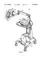
- FIG. 1is a perspective view of an injector in accordance with principles of the present invention, including a power head, console, and power pack (under a cover), with the syringe, pressure jacket, heater blanket and air detection module removed;
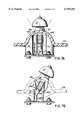
- FIG. 2is a perspective view of the power head of the injector of FIG. 1 with a pressure jacket, syringe and heater blanket mounted thereto, showing the power head display, hand-operated control, and support arm mounting in greater detail;
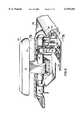
- FIG. 3is a disassembled view of the internal structure of the power head of FIG. 2 illustrating details of the face plate, circuit board, plunger ram drive and housing;
- FIG. 4is a partial sectional view of the internal structure of an assembled power head, taken along lines 4--4 in FIG. 3;
- FIG. 5is a partial sectional view taken along lines 5--5 of FIG. 4, showing the relative positions of the circuit board, housing, display and magnetic conductors within the housing;
- FIG. 6is a perspective, partial sectional view of the hand-operated control assembly
- FIG. 7Ais a cross-sectional view of the hand-operated control assembly of FIG. 6 taken along lines 7A--7A of FIG. 6, showing the return and detent springs;
- FIG. 7Bis a cross-sectional view of the hand-operated control assembly showing the hand-operated control lever displaced from the home position and into contact with the detent spring;
- FIG. 7Cis an electrical schematic diagram of the electrical circuit formed by the hand-operated control lever, return and detent springs
- FIG. 8is a perspective drawing of the heater blanket used to warm fluid in the syringe mounted to the injector
- FIG. 9is a partial cross-sectional view of a syringe mounted in the pressure jacket with the air detection module in place, showing the internal structure of the air detection module and its interaction with the structure of the syringe tip;
- FIG. 10is a view of the air detection module taken along lines 10--10 of FIG. 9, with the syringe and pressure jacket removed;
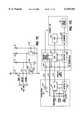
- FIG. 11Ais an electrical block diagram illustrating the analog circuitry in the power head, including the temperature control, air detection, and hand-operated control circuitry;
- FIG. 11Bis an electrical block diagram of the digital control circuitry in the power head, including the central processing unit, monitor microcontroller, digital status, control and interface connections;
- FIG. 11Cis an electrical block diagram of the central processing units and microcontrollers in the power head, power pack and console and their interconnection;
- FIG. 12illustrates the heater blanket temperature control methodology used by the CPU of the power head
- FIG. 13Aillustrates the ranges of tilt angle established by software in the power head microprocessor to control operations of the injector
- FIG. 13Billustrates the elements in the display on the power head, and a typical display output as it would appear when the power head is at a first tilt angle
- FIG. 13Cillustrates the display output of the same information as FIG. 13B, as it would appear when the power head is at a second tilt angle.
- an injector 20 in accordance with the present inventionincludes various functional components, such as a power head 22, a console 24 and power pack 26 (mounted inside of a cover).
- a syringe 36(FIG. 2)is mounted to the injector 20 in the face plate 28 of the power head 22, and the various injector controls are used to fill the syringe with, e.g., contrast media for a CT, Angiographic or other procedure, which media is then injected into a subject under investigation under operator or pre-programmed control.
- the injector power head 22includes a hand-operated movement control lever 29 for use in controlling the movement of the internal drive motor, and a display 30 for indicating to the operator the current status and operating parameters of the injector.
- the console 24includes a touch screen display 32 which may be used by the operator to remotely control operation of the injector 20, and may also be used to specify and store programs for automatic injection by the injector 20, which can later be automatically executed by the injector upon initiation by the operator.
- Power head 22 and console 24connect through cabling (not shown) to the power pack 26.
- Power pack 26includes a power supply for the injector, interface circuitry for communicating between the console 24 and power head 22, and further circuitry permitting connection of the injector 20 to remote units such as remote consoles, remote hand or foot control switches, or other original equipment manufacturer (OEM) remote control connections allowing, for example, the operation of injector 20 to be synchronized with the x-ray exposure of an imaging system.
- OEMoriginal equipment manufacturer
- Power head 22, console 24 and power pack 26are mounted to a carriage 34 which includes a support arm 35 for supporting power head 22 for easy positioning of power head 22 in the vicinity of the examination subject.
- a carriage 34which includes a support arm 35 for supporting power head 22 for easy positioning of power head 22 in the vicinity of the examination subject.
- console 24 and power pack 26may be placed on a table or mounted on an electronics rack in an examination room while power head 22 is supported by a ceiling, floor or wall mounted support arm.
- a syringe 36 and pressure jacket 38are mounted to power head 22, so that the motor internal to power head 22 may be energized to move a plunger 37 within the barrel of syringe 36 toward and away from a discharge tip 40 of the syringe, to thereby expel fluid from the syringe 36 or fill the syringe with fluid.
- Pressure jacket 38provides support to the outer walls of syringe 36 to protect the walls of syringe 36 from failure at high injection pressures.
- Syringe 36 and pressure jacket 38are made of a clear plastic material through which the operator can view the current location of plunger 37 and any fluid or air in the syringe between plunger 37 and discharge tip 40. Accordingly, as described above, an operator may tilt power head 22 upward, fill syringe 36 from a source of fluid while visually monitoring the filling process, then connect the injector to tubing leading to the patient, expel air from the tubing and syringe while visually monitoring the level of fluid in the syringe, and then once air has been expelled, tilt the injector downward and proceed to inject fluid into a subject.
- power head 22includes the hand-operated movement control, which is in the form of the rotatable lever 29.
- lever 29is rotatable on an axis of rotation inside of power head 22.
- the hand-operated control lever 29is left in its home position, illustrated in FIG. 2, no plunger motion is generated by power head 22.
- hand-operated control lever 29is rotated toward syringe 36, forward plunger motion is generated by power head 22, expelling fluid or air from syringe 36.
- hand-operated control lever 29when hand-operated control lever 29 is rotated away from syringe 36, reverse plunger motion is generated by power head 22, filling syringe 36 with fluid or air. Further details on the construction and operation of hand-operated control lever 29 will be elaborated below in connection with FIGS. 6-7C.
- a heater blanket 42is installed abutting the exterior wall of pressure jacket 38.
- Heater blanket 42includes an electrical heater which generates heat for regulating the temperature of fluid within syringe 36.
- Heater blanket 42(which is separately illustrated in FIG. 8) is mounted to a post 44 extending from face plate 28, holding heater blanket 42 in thermal contact with pressure jacket 38.
- an indicator lamp 46(covered by a light-diffusing cover) which indicates the status of the power head, as discussed in further detail below.
- Power head 22is constructed from two external half-housings 47a and 47b.
- Half-housings 47a and 47bmate to form the complete housing for power head 22.
- the upper half-housing 47aincludes an aperture through which the display 30 can be viewed, the indicator lamp 46, and bearing surfaces for supporting a shaft 48 to which hand-operated control lever 29 is attached. Details of the hand-operated control lever structure mounted internally to upper half-housing 47a are discussed in further detail below.
- Lower half-housing 47bincludes an aperture through which a knob 49 is mounted and coupled to the internal drive train. Knob 49 can be rotated by hand to move the drive train of the plunger drive ram, to allow precise control of ram movements, and also to permit movement if an electrical failure disables the power head 22.
- a second aperture 51 in lower half-housing 47bis used to connect the power head circuit board 55 (see below) to electrical lines leading from the heater blanket 42 (see FIGS. 2, 8) and air detector attachment (see FIGS. 9, 10).
- Lower half-housing 47bfurther includes a mounting track (opposite to indentation 50 inside of half-housing 47b) for receiving a mount 52 for supporting half-housing 47b on an articulated arm such as arm 35 shown in FIGS. 1 and 2.
- Mount 52may be inserted into the mounting track of lower half-housing 47b from either side of power head 22, facilitating mounting of power head 22 on either side of an examination table.
- a knob 53holds mount 52 in place in the mounting track in lower half-housing 47b.
- circuit board 55which supports substantially all of the electrical circuitry for controlling the operations of power head 22. Notable components found on circuit board 55 include magnetic detectors 56a, 56b and 56c and flag sensor 58. The main circuit board also includes the indicator lamp 46 (not shown). The functions of detectors 56a, 56b and 56c and flag sensor 58 will be elaborated more fully below.
- Drive train 60for the plunger drive ram 62.
- Drive train 60includes a rotary electric motor 63, controlled by circuit board 55, which (via a gear box 68) rotates a drive pinion 64.
- Pinion 64meshes with a main gear 65, which rotates a ball screw 66.
- Plunger drive ram 62is mounted to a ball screw nut 67 which converts rotation of ball screw 66 into linear translation of plunger drive ram 62 into or out of power head 22, thus moving the plunger 37 (FIG. 2) of a syringe 36 mounted to power head 22.
- Knob 49is coupled to the axis of drive pinion 64, thus permitting hand rotation of the drive train 60 and motion of the plunger drive ram.
- drive train 60These elements of the drive train 60 are mounted to a drive housing 69.
- the front surface 70 of drive housing 69is exposed.
- the face plate 28 of the injectoris attached to front surface 70, to allow a syringe to be mounted to the front surface 70 of the drive housing 69 so that plunger drive ram 62 may engage and move the syringe plunger 37.
- the face plate 28is attached to front surface 70 by a hinged connection, using a hinge pin 72.
- face plate 28may rotate in direction 73 on hinge pin 72, and may also translate in direction 74 over a limited distance along hinge pin. This combination of rotational and translational movement allows face plate 28 to be engaged and disengaged from front surface 70, permitting loading and removal of syringes from face plate 28, and simultaneous coupling and uncoupling of the syringe plunger from plunger drive ram 62.
- a cam lever 78is mounted to drive housing 69 between face plate 28 and drive housing 69.
- Cam lever 78is affixed to and rotates a cam lever shaft 79, which is mounted in drive housing 69.
- Cam lever 78includes a button 81 which projects toward face plate 28. Button 81 mates with a channel 80 formed in the inner surface of face plate 28 (see FIG. 4), so that rotation of cam lever 78 causes button 81 to translate face plate 28 along direction 74, engaging or disengaging tabs 75a and 75b from slots 76a and 76b.
- a flag washer 82is mounted to cam lever shaft 79 and held in place with a nut 83.
- the apertures in flag washer 82 and cam lever 78 which connect to cam lever shaft 79are keyed, so that cam lever 78 and flag washer 82 are oriented in a consistent manner relative to each other. Because flag washer 82 and cam lever 78 are both keyed to shaft 79, rotation of cam lever 78 will cause shaft 79 and flag washer 82 to rotate.
- Flag surface 84extends from flag washer 82; movement of this flag surface due to rotation of cam lever 78 is detected as noted below and used to determine whether face plate 28 is engaged to the power head 22.
- flag washer 82is positioned opposite to flag sensor 58 on circuit board 55.
- Flag sensor 58produces a light beam which, when flag surface 84 is opposite to sensor 58, will be reflected and detected by sensor 58.
- Cam lever 78 and flag washer 82are keyed into shaft 79 so that flag surface 84 is rotated opposite to detector 58 only when cam lever 78 is positioned as shown in FIG. 4, in which position cam lever 78 will have translated cam face plate 28 into engagement with the front face 70 of drive housing 69, permitting injection.
- flag surface 84is opposite to flag sensor 58, this indicates that the face plate is in the closed position, ready for filling or injection.
- Power head 22includes a safety lock-out which prevents rotation of cam lever 78 to a disengaged position when plunger drive ram 62 is other than fully retracted.
- a spring loaded lockout plate 86is mounted to drive housing 69 in a manner to permit translational movement in direction 90. Screws 87 hold lockout plate 86 in position on drive housing 69 to allow this translational movement.
- Spring 88is coupled between lockout plate 86 and drive housing 69 to provide force tending to slide lockout plate 86 toward front surface 70 of drive housing 69, i.e., into the position shown in FIG. 4.
- lockout plate 86When lockout plate 86 is in this forward most position, the front corner 89 of lockout plate 86 is positioned adjacent to flag washer 82, as seen in FIG. 4. As a result, interference between a notch 85 (see FIG. 3) in flag washer 82 and front corner 89 of lockout plate 86 prevents rotation of flag washer 82 (and cam lever 78) from the engaged position shown in FIG. 4 to a position where face plate 28 will disengage from front surface 70 of drive housing 69, and can be rotated away from front surface 70 to replace a syringe. However, when lockout plate slides backward in direction 90 (against the force of spring 88), this interference between front corner 89 and notch 85 in flag washer 82 is eliminated, allowing cam lever 78 to rotate to a disengaged position.
- a fitting 91 on plunger drive ram 62is positioned to engage to lockout plate 86, so that when plunger drive ram 61 is withdrawn from the face plate 28 to a fully rearward position, fitting 91 will engage lockout plate 86 and move it to its backward position.
- the force of spring 88moves lockout plate into its forward position.
- face plate 28cannot be translated in direction 74 or disengaged from front surface 70 of drive housing 69 unless the plunger drive ram 62 is at its fully rearward position. This interlock prevents the operator from attempting to disengage face plate 28 from front surface 70 while plunger drive ram 62 is projecting inside of a syringe mounted to face plate 28.
- FIGS. 4 and 5there is illustrated three magnetic conductors 94a, 94b and 94c. These conductors are manufactured of a high permeability, low retentivity material such as steel or iron, and are inserted through apertures in the front surface 70 of drive housing 69.
- Each face plate 20may be provided with permanent magnets inserted at positions which are in registration with the positions of the three magnetic conductors 94a, 94b and 94c. There may be three, two, one or no permanent magnets, and the magnets may be oriented with their North or South poles facing magnetic conductors 94a, 94b and 94c.
- the face plate 28 shown in FIG. 4includes two permanent magnets 96a and 96b positioned in registration with magnetic conductors 94a and 94b.
- the face plate shown in FIG. 4does not, however, have a magnet positioned opposite to magnetic conductor 94c.
- Multiple different face plates 28may be used with the power head 22 illustrated in FIGS. 3 and 4. Different face plates 28 may be used to adapt the power head 22 to use different types of syringe 36; for example, one face plate may be sized for use with low capacity pediatric syringes, whereas another is sized for use with adult-capacity syringes. Pre-filled syringes may have different sizes or dimensions than syringes which are purchased empty. Different face plates 28 are needed to accommodate these different syringe sizes.
- control circuitry on circuit board 55It is necessary for the control circuitry on circuit board 55 to be able to detect which face plate is installed on power head 22. Firstly, the control circuitry must determine whether an air detection module is attached to the face plate. Also, different syringe 36 types may have differing lengths, in which case power head 22 must be able to compensate for the length variations when determining the end-of-travel position of the plunger drive ram and when computing the volume of fluid in the syringe 36. Similarly, syringes of different diameters will produce different flow rates for the same rate of travel of the plunger drive ram 62; the control circuitry must compensate for this when converting a requested flow rate into movement of the plunger drive ram 62.
- each different face plate 28has a unique combination of permanent magnets installed therein, in registration with the magnetic conductors 94a, 94b and 94c in the front surface 70 of the drive housing 69.
- the face plate illustrated in FIG. 4has two permanent magnets, opposite conductors 94a and 94b.
- Another face platemight have only one permanent magnet, positioned opposite conductor 94b.
- a third face platemight have three permanent magnets positioned opposite all three conductors 94a, 94b and 94c.
- the control circuit of the power head 22includes magnetic detectors 56a, 56b and 56c, which may for example be Hall effect sensors (or, alternatively, reed switches). These three magnetic detectors 56a, 56b and 56c are positioned near an edge of circuit board 55 in registration with the inner ends of the three magnetic conductors 94, as can be seen by comparing FIGS. 4 and 5.
- the drive housing 69is manufactured of a non-magnetic material such as Aluminum.
- magnetic fields produced by permanent magnets 96a and 96bare channeled through the magnetically permeable conductors 94a, 94b and 94c, and thus brought into the vicinity of detectors 56a, 56b and 56c, so that the presence or absence of permanent magnets in face plate 28 can be detected remotely from the face plate 28 by detectors on circuit board 55.
- the magnetic conductorsby channeling magnetic fields from permanent magnets in the face plate 28 to remotely located detectors on circuit board 55, provide a substantial reduction in cost of the electronic portion of the power head 22.
- free-standing magnetic detectorsare available, and could be mounted to the front surface 70 of drive housing 69, free-standing magnetic detectors are typically substantially more expensive to purchase than printed circuit board mountable detectors. Furthermore, the use of free-standing magnetic detectors would entail manufacturing multiple separate circuit boards and/or harnesses and installing them in the power head housing with appropriate cabling connections to the main circuit board, which would make the manufacture of power head 22 more complex, expensive and time-consuming, as compared the present embodiment where the detectors are included on the main circuit board. Accordingly, the use of magnetic conductors 94a, 94b and 94c substantially reduces the cost of manufacturing power head 22.
- hand-operated control lever 29is rotated in a forward direction or reverse direction to indicate the operator's desire to move the plunger drive ram forward or in reverse.
- a rotary potentiometer 98is coupled to shaft 48 of lever 29, so that rotation of lever 29 rotates a wiper inside of potentiometer 98, creating a changing resistance that can be detected by the power head control circuitry.
- control circuitrywhen control lever 29 is rotated forward in direction 99, the control circuitry, detecting this rotation from electrical signals produced by potentiometer 98, causes the plunger drive ram 62 to move forward, i.e., outward from the power head housing, at a velocity proportional to the angle of deflection of control lever 29 away from the home position shown in FIG. 6.
- the control circuitrydetects this rotation from electrical signals produced by potentiometer 98, and causes the plunger drive ram 62 to move backward, i.e., into the power head housing, at a velocity proportional to the angle of deflection of control lever 29 away from the home position shown in FIG. 6.
- FIG. 6illustrates the two return springs 102a and 102b which engage shaft 48 and produce torque tending to return shaft 48 to the home position shown in FIG. 6. Also shown is the combined flag/contact 104 which surrounds shaft 48 and contacts return springs 102a and 102b. Return springs 102a and 102b make contact with flag/contact 104 and thereby form an electrical connection to each other, and also apply spring torque tending to return shaft 48 to the home position.
- detent spring 106the function of which will be elaborated below
- flag detector 108which is an optical detector which generates a light pulse for transmission across a gap, detects receipt of the light pulse on the opposite side of this gap, and generates a digital signal indicative of whether the gap is obstructed in such a way as to prevent light transmission.
- flag/contact 104is positioned equidistant between return springs 102a and 102b, which apply opposing torques to lever 29, tending to hold lever 29 in this home position.
- flag 105 of combined flag/contact 104is positioned inside of flag sensor 108, causing sensor 108 to produce a digital signal indicating that the lever is in its home position.
- the control circuit of power head 22can determine that no plunger motion is being requested through the hand-operated movement control.
- control circuitmay read the electrical signal produced by potentiometer 98 to determine the position of the lever and produce the appropriate motion of the plunger drive ram.
- the velocity of motion of the plunger driveis proportional to the extent of rotation of lever 29 away from its home position.
- the mechanical structure of return springs 102a and 102bensures that a return torque is applied to lever 29 as lever 29 is rotated to increasing angles away from the home position.
- this return torquemay be approximately equal at all deflection angles, or may increase or decrease over increasing deflection angles. An increasing return torque with deflection angle, may be useful in providing the operator with additional feedback on the plunger velocity.
- the operatorWhen filling a syringe, there is an ideal maximum speed at which fluid can be drawn into the syringe without forming air bubbles in the fluid due to non-laminar flows. To speed the filling of syringes, the operator should have feedback as to when this ideal speed has been reached, so that syringes can be filled at this optimal speed.
- the purpose of the detent spring 106is to provide the operator with mechanical feedback of the angle of deflection of lever 29 which corresponds approximately to the ideal fill speed. More specifically, the control circuit of power head 22 establishes that the plunger drive will move at near to the ideal fill speed when lever 29 has been rotated such that flag 105 is in contact with detent spring 106. Accordingly, an operator wishing to fill a syringe at a near ideal speed, can rotate lever 29 until the increasing torque of the detent is noted, and then hold lever 29 at the detent location to fill the syringe.
- the return springs 102, flag/contact 104 and return spring 106are not only mechanically active to provide mechanical feedback to the operator, but are also electrical elements in the control circuit of power head 22. Specifically, referring to FIG. 7C, each of these elements is an electrical circuit element in a circuit for producing digital control signals used by the control of power head 22.
- return springs 102a and 102b, and the flag/contact therebetweenare connected with a resistor 110 in a series connection between a digital +5 volt power supply and ground.
- a signal line 115 extending from between resistor 110 and spring 102acarries a logic voltage signal indicating whether a current-carrying electrical contact is completed between springs 102a and 102b and flag/contact 104. Under normal conditions, there should be an electrical path through this path to ground, holding the voltage on line 115 at a low level, indicating proper operation.
- the detent spring 106forms an electrical contact in a series connection with a resistor 111, and a detent signal line 116 extends from between resistor 111 and the detent spring. If control lever 29 is not rotated into the detent spring, line 116 will be pulled to a high level, indicating that the control lever 29 is not at the detent. However, if control lever 29 is rotated such that flag 105 contacts detent spring 106, line 116 will be pulled to a low level, indicating that control lever 29 has been rotated to the detent.
- the signal on line 116may be used in several ways. For example, the signal may be used to calibrate the hand-operated control so that the angle of lever rotation corresponding to the detent is equal to the ideal fill speed.
- the signalmay be used to prevent reverse movement of the ram at a speed faster than the ideal fill speed.
- the signalmay be used to establish a "dead zone" of motion, in which the ram will move at the ideal fill speed, while permitting the lever to be rotated beyond the "dead zone” to produce faster reverse speeds.
- FIG. 7Calso illustrates the circuit details of the flag detector 108; a light emitting diode is energized with a bias current via resistor 113; when light passes through the gap in detector 108 and strikes the base of a phototransistor in detector 108, the phototransistor draws current through resistor 112 to drive a home signal on line 117 to a low value, indicating that control lever 29 is not in its home position. Otherwise, if light is unable to pass to the base of the phototransistor in detector 108, current is not drawn through resistor 112 and the home signal on line 117 is pulled to a high value, indicating that control lever 29 is in its home position.
- the control circuitry for power head 22can thus use the home signal on line 117 to determine whether to discontinue motion of the plunger drive ram.
- the heater blanket 42 used with the power head 22 in accordance with the present inventionincludes an annular plastic section 118 and a molded plastic base.
- Plastic section 118includes a filament 120 of electrically resistive wire, which generates heat when an electrical current is driven through it via a suitable electrical power source.
- Filament 120extends throughout the region of annular section 118 which is in contact with pressure jacket 38 when heater blanket 42 is mounted to post 44 as shown in FIG. 2, and terminates at either end in electrical leads encased in an insulating cable 117 which can be plugged into the power head 22 control circuitry through aperture 51 (FIG. 3) as is illustrated in FIG. 2.
- filament 120When current from the power head is forced through the leads in cable 117 and through the filament 120, filament 120 generates an even heat which warms fluid inside of the syringe in pressure jacket 38.
- Annular section 118might be opaque, or may be clear or translucent. If annular section 118 is clear, filament 120 could be seen through (as in an automobile defroster or a window screen) so that the operator is better able to visualize fluid inside of the syringe through the annular section, pressure jacket 38 and syringe wall. This may be advantageous in applications where the operator's primary line of sight to the interior of the syringe might otherwise be obscured by the heater blanket.
- Base 119 of heater blanketis formed of a soft plastic, overmolded on a resilient skeleton.
- the resilient skeletonis shaped with a bowl 121 sized for a slight interference fit with post 44.
- heater blanket 42may be snap fit over post 44 for convenient installation and removal (e.g., for cleaning).
- the air detection module 122is mounted to the end of post 44, and is configured to wrap around the distal end of pressure jacket 38 and into contact with an outwardly projecting collar 124a surrounding the discharge neck of syringe 36.
- the air detection moduleincludes a light source 126 and light sensor 127.
- Light sensor 127is a commercially available circuit, which includes sensor 127 and an oscilleator which produces a trigger signal indicating when light source 126 should be stimulated to produce a light beam.
- the output of sensor 127is a digital signal indicating whether the light beam is received by detector in response to triggering of the light source.
- FIGS. 9 and 10show illustrative ray traces showing the paths taken by light rays emitted from light source 126.
- Light source 126includes an integral focusing lens, and collar 124a on the discharge neck of syringe 36 forms a second focussing lens. These lenses act in concert to direct light from light source 126 along path 129 toward collar 124b on the discharge neck of syringe 36.
- the internal shape of collar 124bforms a corner reflector, so that light impingent upon collar 124b from light source 126 is reflected toward light sensor 127.
- air detection module 122is structured to ensure solid contact between light source 126, light sensor 127 and the surface of collar 124a on syringe 36.
- the air detection module 122has a spring-metal interior skeleton 133, which is overmolded with a soft flexible plastic 134.
- One end of spring metal skeleton 133is mounted to post 44 by mounting screws 135 (which are accessible via voids in the plastic overmold 134).
- the opposite end of skeleton 133supports the air detector module, which includes a hard plastic molding 136 supporting the light source 126 and light sensor 127.
- Molding 136includes a beveled section 137 sized to fit into a chamfer 138 at the aperture of pressure jacket 38. The interaction of beveled section 137 and chamfer 138 ensure precise positioning of light source 126 and light sensor 127 relative to pressure jacket 38.
- the neck of the syringe 36is sized with a slight interference fit, so that collar 124a contacts and slightly deflects air detection module 122 when the syringe 36 is inserted into pressure jacket 38, flexing spring skeleton 133 and resulting in a steady application force of light source 126 and light sensor 127 against collar 124a of syringe 36.
- This application forceensures good communication of light from source 126 into the neck of syringe 36 and from the neck of syringe 36 into light sensor 127.
- the air detection moduleincorporates therein, a commercially available synchronous detection circuit 140, which includes an internal oscillator generating trigger pulses on line 141, and, contemporaneously with each trigger pulse, detects electrical signals on line 142 indicating that light has been received at light sensor 127. So long as light is detected contemporaneously with each trigger pulse, a high level signal is produced on line 143. Due to the application to which circuit 140 is applied in accordance with the invention, the signal on line 143 indicates whether air has been detected in the neck of the syringe 36.
- the control circuit of power head 22may control the light intensity applied to the air bubble detector, to control the sensitivity of the detector. To do so, the control circuit produces a pulse width modulated (PWM) digital signal on line 145. This PWM signal is filtered by a low-pass filter circuit 146 to produce an analog control voltage, which controls an adjustable regulator 147 to produce the power signal on line 148 for circuit 140.
- PWMpulse width modulated
- a PNP optp-transistor 149In response to the trigger signal on line 141, a PNP optp-transistor 149 is turned “on”, causing the power signal on line 148 to energize light source 126. Thus, the voltage of the power signal on line 148 directly affects the intensity of light generated by light source 126.
- the trigger signal on line 141is connected to the base of PNP opto-transistor 149 via a light emitting diode in an opto-isolator 150. Accordingly, the opto-transistor in opto-isolator 150 will turn “on” whenever the trigger signal is activated, causing a "low” level to appear on line 151. Thus, if the synchronous air detector circuit 140 is operating properly and producing periodic trigger signals, pulses will appear on line 151, which can be detected by the control circuit to verify that the oscillator in circuit 140 is operating properly.
- FIG. 11Aalso illustrates the analog-to-digital (A/D) converter 152 incorporated into the power head control circuit for quantizing analog signals produced by various electrical elements.
- potentiometer 98(see FIG. 6) is connected to the shaft 48 of fill/expel lever 29.
- the wiper of this potentiometeris connected to a signal line 154, which carries an analog voltage indicative of the rotational position of the fill/expel lever shaft 48.
- the opposite ends of the potentiometerare connected to a reference voltage and to ground, so that the voltage on line 154 lies somewhere between these extremes, dependent upon the rotational position of fill/expel lever 29.
- Line 154connects to A/D converter 152, and converter 152 converts the analog voltage on line 154 to a digital signal on a "SPI" serial interface bus 156, upon request from the CPU (see FIG. 11B), so that the CPU can determine the position of fill/expel lever 29 and react accordingly.
- SPIserial interface bus
- A/D converter 152Other analog voltages are also input to A/D converter 152.
- a single-chip accelerometeris configured as a tilt sensor 158, to produce an analog voltage on line 159 indicative of the angle of tilt of sensor 158.
- a suitable single chip accelerometer for this purposeis available from Analog Devices of Norwood, Mass. as part no. ADXL05AH.
- Sensor 158is mounted to circuit board 55, and therefore produces an output voltage indicative of the tilt of power head 22 relative to the direction of Earth gravity. This analog tilt signal is converted and input to the CPU for use, as noted below, in controlling the display and other operational features of power head 22.
- a third analog signalis produced by a linear potentiometer 160, the wiper of which is mechanically connected to the plunger drive ram 62, and moved in response to movement of the plunger drive ram.
- the voltage of the wiper on line 161is an analog signal representative of the position of the ram between its rearward most and forward most positions. This signal is converted and used by the CPU to determine the position of the ram and, among other things, the syringe volume remaining.
- thermistors 163A and 163bTwo additional analog signals are produced by thermistors 163A and 163b, which are series connected with bias resistors to produce voltages on lines 164a and 164b which reflect the temperature of the thermistors.
- the temperature measurement obtained from these thermistorsis then used to control the power applied through the heater blanket to warm the fluid in the syringe 36.
- the heat power applied to the syringeis varied proportion to the ambient temperature, as measured by thermistors 163a and 164a, to maintain the fluid at the target temperature, e.g., 30 degrees Celsius.
- Thermistors 163a and 163bare duplicative, that is, both measure the same temperature and their measurements are compared to ensure near agreement. As a result, failure of a thermistor can be detected from disagreement between the temperature readings obtained from the thermistors, preventing loss of temperature control.
- Thermistors 163a and 163bmay be mounted internally to power head 22, on circuit board 55. Alternatively, thermistors 163a and 163b may be external to the housing, to ensure more accurate temperature readings, or both options may be allowed by providing internally-mounted thermistors which can be disabled if substitute externally-mounted thermistors are connected to the power head 22.
- power head 22controls the heat power applied to the syringe 36 through heater blanket 42.
- the CPU(see FIG. 11B) produces a pulse width modulated (PWM) control signal on line 166 which is used to control the heat power applied to the heater blanket filament 120.
- PWMpulse width modulated
- the PWM signal on line 166is low pass filtered by filter 167, producing an analog control signal which controls an adjustable regulator 168.
- the output of regulator 168 on line 169is a variable voltage which is applied across heater blanket filament 120, causing heater filament 120 to produce heat.
- An instrumentation amplifier 170filters and conditions the voltage across filament 120 to produce an analog output signal on line 171 which is proportional to the voltage applied to the heater blanket filament 120.
- a sense resistor 173is series connected with heater filament 120, so that the current in heater filament 120 passes through sense resistor 173, producing a voltage on sense resistor proportional to the current flowing through heater filament 120.
- Sense resistorhas a resistance substantially smaller than that of heater filament 120, so that the small voltage drop across sense resistor 173 is not a substantial percentage of the voltage drop across heater filament 120.
- the voltage drop across sense resistor 173is amplified and filtered by a gain/filter circuit 172, producing an analog voltage on line 174 which is proportional to the current flowing through heater filament 120.
- Lines 171 and 174are connected to A/D converter 152, and the voltages on lines 171 and 174 are converted thereby to digital signals which can be read by the CPU. Accordingly, the CPU can determine the current and voltage drop across heater filament 120, and use these values to determine the heat output of heater filament 120. This permits the CPU to perform closed-loop control of the heater blanket heat output, as discussed below in connection FIG. 12.
- the CPU 175which may be a 68332 microprocessor, available from Motorola, controls data and address busses 176 connecting CPU 175 to random access memory (RAM) 178 and a flash memory 177.
- CPU 175also controls an SPI serial interface bus 156 for communicating with A/D converter 152, display 30 and a monitor microcontroller 192.
- CPU 175further includes an RS-422 serial interface 179 connecting CPU 175 to a CPU in the power pack (see FIG. 11C).
- CPU 175includes a number of digital data input lines for monitoring operation of power head 22. Specifically, CPU 175 receives the detent signal on line 116, safe signal on line 115 and home signal on line 117, enabling CPU to receive input on the state of operation of the hand-operated movement lever as discussed above. CPU 175 also receives the bubble signal on line 143 from which CPU 175 may detect air in the syringe neck and take appropriate action, and in addition, CPU 175 receives the bubble detection oscillator signal on line 151, which can be used as noted above to confirm proper operation of the oscillator in the air detection module 122. Further, CPU 175 receives the output of flag sensor 58, from which CPU 175 may determine whether the face plate is securely locked to the housing of power head 22. Furthermore, CPU 175 receives digital signals from the three magnetic detectors 56a, 56b and 56c indicative of which of several possible face plates are mounted to power head 22, allowing CPU 175 to adjust its operation accordingly.
- CPU 175also receives digital input signals from parallel rotary encoders 182, which produce pulse signals on lines 183a and 183b indicative of rotation of the plunger drive train. These pulses are used by CPU 175 to confirm movement of the plunger drive ram. Lines 183a and 183b are also connected to the power pack (see FIG. 11C) so that the power pack CPU may perform closed loop control of plunger movement by counting encoder pulses and comparing the rate of receipt of encoder pulses to a desired rate.
- a closed loop controlis disclosed in U.S. Pat. No. 4,812,724, which is incorporated by reference herein in its entirety.
- CPU 175also produces multiple digital control signals, including those noted above, i.e., the air bubble detector power PWM signal on line 145, and the heater blanket power PWM signal on line 166, both being pulse-width modulated by CPU 175 to produce desired power levels.
- CPU 175further produces output signals on lines 187 for illuminating light emitting diodes in lamp 46 (FIG. 2) which indicate the status of operation of the injector. Additional output signals on SPI serial bus lines 156 control the display 30.
- CPU 175uses the above-noted inputs and outputs to perform primary control of power head 22 under control of software resident in CPU 175 or read from RAM 178.
- CPU 175is also connected, through SPI serial bus 156, to a microcontroller 192 which serves as a monitor, for monitoring operation of CPU 175 to ensure the absence of software or hardware failures.
- Monitor microcontroller 192performs this function by receiving, through bus 156, an indication of the current operational state of CPU 175.
- CPU 175indicates, through bus 156, the operating state of CPU 175, i.e., whether CPU 175 is requesting movement of the plunger or not, and whether the motion is being requested in response to hand-operated or automatic (programmed) control, and potentially other specific information such as the rate of movement that is being requested.
- Monitor microcontroller 192reads this state information from lines 156, and compares this information to crucial digital input signals from the power head 22, to ensure consistency therebetween.
- microcontroller 192receives the safe signal on line 115 and home signal on line 117. If these signals indicate that the hand-operated control is in the home position, then CPU 175 should not be generating movement under hand-operated control. If a spring has failed (as indicated by the signal on line 115), this should be reflected in the state of the CPU 175. Therefore, under these conditions, microcontroller 192 reads the state information from bus 156 to ensure that CPU 175 is not acting inconsistently with the signals from the hand-operated control.
- microcontroller 192receives the output signals from rotary encoders 182 on lines 183a and 183b. Microcontroller 192 checks these signals to determine whether the plunger drive ram is moving, to ensure the drive ram is moving only when the state of CPU 175 indicates that the drive ram should be moving, and not otherwise. Furthermore, in this connection it should be noted that microcontroller 192 receives the door flag signal from door flag sensor 58. If this signal indicates that the door of power head 22 is other than in the locked position, CPU 175 should not be requesting movement of the plunger drive ram, and microcontroller 192 confirms this by checking for the absence of pulses from encoders 182.
- each of power head 22, power pack 26 and console 24contains a CPU 175, 192 and 194, respectively.
- These CPUsinteract through external interfaces to perform control of the injector.
- the plunger drive ramcan be controlled through the lever 29 on power head 22 (as discussed above), or can be automatically controlled by an operator entering programs for injections using touch screen 32 of console 24 (using CPU 194), and then enabling the programmed injection.
- the injection parameterssuch as motor speed and injection volumes will then be produced by console CPU 194, which communicates with power pack CPU 192 to cause these programmed actions to take place.
- an automatic injectionmay be enabled using the touch screen 32, or an injection may be started using a hand switch or OEM remote trigger connected to power pack 26. In either case, the appropriate one of CPUs 192 and 194 generates an enabling signal to initiate the automatic injection.
- the power head CPU 175is associated with a monitor microcontroller 192 for monitoring the state of CPU 175 to ensure its actions are consistent with input signals from power head 22.
- CPUs 192 and 194are also associated with monitor microcontrollers 196 and 198, respectively, which monitor the actions of the associated CPUs 196 and 198 to ensure consistent, error free behavior.
- Monitor microcontrollers 192, 196 and 198communicate with each other in a manner which parallels the communication of CPUs 175, 192 and 194. Specifically, the three monitor microcontrollers exchange state information received from their associated CPUs to ensure that the three CPUs are in similar states of operation, e.g., hand-operated movement, automatic movement, no movement, etc. Furthermore, each of the microcontrollers receives external input signals to ensure that state transitions which should occur are, in fact, occurring. Thus, microcontroller 196 receives the hand or OEM trigger signals so that microcontroller 196 can determine when an automatic injection has been triggered. Microcontroller 198 receives input signals from touch screen 32 so it, too, can determine when an automatic injection has been triggered. Other monitoring functions can be performed, as desired to ensure correct and consistent operation of CPUs 175, 192 and 194.
- power head CPU 175delivers a control signal to power pack 26, requesting a ram movement.
- Power pack 26contains the motor servo control circuitry for producing an appropriate power signal on line 200 to drive motor 63, and to perform closed loop control of motor movements in response to encoder pulses on lines 183.
- the monitor microcontrollerscan discontinue power flow to motor 63 through a hardware disable, represented by switch 202 in series with power line 200, thereby ceasing any movement of the plunger drive.
- This hardware disableensures that the monitor microcontrollers can prevent erroneous injection of fluid under error conditions.
- CPU 175To perform heater blanket control, CPU 175 initially measures the ambient temperature using the first and second thermistors 163a and 163b (steps 204 and 206). (As part of these steps, CPU 175 may reference stored compensation tables for converting thermistor voltages to corresponding temperatures.) CPU 175 then determines whether these temperature readings are consistent with each other (step 208). If not, this indicates a fault in a thermistor, and an alarm is generated, and the heater blanket is disabled (step 210).
- CPU 175proceeds to determine a desired heater blanket power output level P OUT (step 210), based on the measured ambient temperature T AMBIENT .
- a thermal modelis used to calculate the power required to maintain the fluid temperature at 37° C. with the measured ambient temperature. The power will vary according to this model over the range of ambient temperatures from 0° C. to 32° C. Above an ambient temperature of 32° C., the heater blanket is shut off to avoid over heating the fluid. Below an ambient temperature of 0° C., the power produced by the heater blanket is limited to 8 Watts to avoid overheating the heater filament 120 in the heater blanket.
- Other modelsmight also be used, particularly non-linear models.
- CPU 175produces a PWM signal on line 166 (FIGS. 11A and 11B) at a duty cycle (step 212).
- An initial duty cycleis chosen to begin warming the fluid in the syringe.
- CPU 175reads, from lines 171 and 174 (through A/D converter 152), the analog voltages indicating the voltage and current applied to heater filament 120 (steps 214 and 216). These values are multiplied to determine the actual power being output from the heater blanket, and this power is compared (step 218) to the desired output power computed earlier. If the current output power is approximately equal to the desired power, then the current PWM duty cycle is correct, and CPU 175 will return to step 204 to re-measure the ambient temperature to continue controlling the heater output power.
- CPU 175will proceed first to step 220, and adjust the PWM duty cycle to change the heater output power as needed (by reducing the duty cycle if too much power is being produced, or by increasing the duty cycle if too little power is being produced). Thereafter, CPU 175 will return to step 204 to re-measure ambient temperature to continue controlling the heater output power.
- This temperature control methodologyensures accurate control of the temperature of the fluid in syringe 36, compensating for temperature variations which can be caused by variations in ambient temperature, thus reducing the likelihood of thermal shock in the subject caused by injection of fluid which is not at the desired temperature.
- CPU 175receives a signal from tilt sensor 158 indicative of the angle of power head 22 relative to Earth gravity.
- CPU 175repeatedly samples this signal, and determines the angle of power head 22 with respect Earth gravity (direction 222). All possible angles of rotation are divided into six regions of operation, illustrated in FIG. 13A.
- Region 1is the "fill" region; it is the angle at which the power head 22 should be placed for filling the syringe.
- the power head 22When the power head 22 is at an angle within region 1, or within regions 2a or 2b which are adjacent thereto, the power head will permit hand-operated motion of the plunger drive ram in either the forward or reverse direction, allowing the operator to fill the syringe and remove air from the syringe after initial filling.
- a wide range of movement speedscan be generated with the hand-operated movement control, permitting rapid filling of the syringe.
- Region 4is the "inject" region.
- the hand-operated movement lever 29can be used to move the plunger drive ram in either the forward or reverse directions; however, the range of movement speeds that can be generated with the hand-operated movement control is substantially narrowed as compared to those available in regions 1, 2a or 2b. This permits fine-tuned control of fluid injection (or withdrawal of blood, e.g., to check patency of the catheter) using the hand-operated movement control.
- Regions 3a and 3bcan also be used to perform injection. It may be necessary to use power head tilt angles in these regions if an obese patient or other obstacle prevents the operator from rotating the power head 22 to a fully downward position in region 4. However, since operation in regions 3a and 3b is not advisable, due to the chance that air might be injected into the subject, the operator is prevented from injecting in these regions until a software override is entered via the console touch screen 32. Until this override is entered, the display 30 flashes and the injector will not perform programmed injections. Once the software override has been entered, the display will cease flashing and programmed injections can be performed.
- the hand-operated movement lever 19can be used to move the plunger drive ram in either the forward or reverse directions, with a narrow range of movement speeds, permitting fine-tuned control of fluid injection (or withdrawal) using the hand-operated movement control.
- the display 30 of the power head 22is a segmented display, including segments which can be illuminated to provide injection information such as volume injected, volume remaining, and current flow rate. These segments are arranged so the noted information can be displayed in either a first (see FIG. 13B) or second (see FIG. 13C) orientation.
- CPU 175 in the power head 22drives display 30 to produce the display orientation, using the display elements in the manner illustrated in FIG. 13C, when the power head angle is in regions 1, 2a or 2b. Otherwise, in regions 3a, 3b or 4, CPU 175 drives display 30 to produce the display shown in FIG. 13B.
- the information appearing on the display 30is always upright from the perspective of the operator, facilitating use of the display. (There is a hysteresis included in the detection of the boundaries between the various regions shown in FIG. 13A, to prevent unintended toggling between regions.)
- control circuitcould produce an injection pressure or fill vacuum proportional to the extent of angular displacement of control lever 29 away from the home position, rather than a velocity proportional to the extent of rotation.
- Air bubble detectionmay be performed by an ultrasonic source and ultrasonic detector coupled to the neck of the syringe, in which case air can be detected from the large attenuation of sound in air as compared to fluid.
- the air bubble detectormight be mounted on locations on the syringe other than on the neck.
- the air bubble detectormay be used in connection with the power head control circuitry to perform an automatic syringe-filling function, e.g., to detect when air has been evacuated from the syringe after filling.
- a fully pixilated displaymight be used on the power head 22, and controlled by the power head CPU to produce various orientations of display, not limited to upright and inverted display orientations.
- the invention in its broader aspectsis therefore not limited to the specific details, representative apparatus and method, and illustrative example shown and described. Accordingly, departures may be made from such details without departing from the spirit or scope of applicant's general inventive concept.
Landscapes
- Health & Medical Sciences (AREA)
- Heart & Thoracic Surgery (AREA)
- Life Sciences & Earth Sciences (AREA)
- Engineering & Computer Science (AREA)
- Anesthesiology (AREA)
- Biomedical Technology (AREA)
- Veterinary Medicine (AREA)
- Hematology (AREA)
- Vascular Medicine (AREA)
- Animal Behavior & Ethology (AREA)
- General Health & Medical Sciences (AREA)
- Public Health (AREA)
- Emergency Medicine (AREA)
- Infusion, Injection, And Reservoir Apparatuses (AREA)
- Magnetic Resonance Imaging Apparatus (AREA)
Abstract
Description
Claims (6)
Priority Applications (1)
| Application Number | Priority Date | Filing Date | Title |
|---|---|---|---|
| US09/437,410US6159183A (en) | 1996-11-22 | 1999-11-10 | Medical fluid injector having face plate with magnetic conductors |
Applications Claiming Priority (3)
| Application Number | Priority Date | Filing Date | Title |
|---|---|---|---|
| US08/753,288US5868710A (en) | 1996-11-22 | 1996-11-22 | Medical fluid injector |
| US09/189,470US6004292A (en) | 1996-11-22 | 1998-11-10 | Medical fluid injector |
| US09/437,410US6159183A (en) | 1996-11-22 | 1999-11-10 | Medical fluid injector having face plate with magnetic conductors |
Related Parent Applications (1)
| Application Number | Title | Priority Date | Filing Date |
|---|---|---|---|
| US09/189,470DivisionUS6004292A (en) | 1996-11-22 | 1998-11-10 | Medical fluid injector |
Publications (1)
| Publication Number | Publication Date |
|---|---|
| US6159183Atrue US6159183A (en) | 2000-12-12 |
Family
ID=25030013
Family Applications (5)
| Application Number | Title | Priority Date | Filing Date |
|---|---|---|---|
| US08/753,288Expired - LifetimeUS5868710A (en) | 1996-11-22 | 1996-11-22 | Medical fluid injector |
| US09/189,470Expired - LifetimeUS6004292A (en) | 1996-11-22 | 1998-11-10 | Medical fluid injector |
| US09/189,337Expired - LifetimeUS5925022A (en) | 1996-11-22 | 1998-11-10 | Medical fluid injector |
| US09/437,410Expired - LifetimeUS6159183A (en) | 1996-11-22 | 1999-11-10 | Medical fluid injector having face plate with magnetic conductors |
| US09/447,101Expired - LifetimeUS6254572B1 (en) | 1996-11-22 | 1999-11-22 | Medical fluid injector having watchdog circuit |
Family Applications Before (3)
| Application Number | Title | Priority Date | Filing Date |
|---|---|---|---|
| US08/753,288Expired - LifetimeUS5868710A (en) | 1996-11-22 | 1996-11-22 | Medical fluid injector |
| US09/189,470Expired - LifetimeUS6004292A (en) | 1996-11-22 | 1998-11-10 | Medical fluid injector |
| US09/189,337Expired - LifetimeUS5925022A (en) | 1996-11-22 | 1998-11-10 | Medical fluid injector |
Family Applications After (1)
| Application Number | Title | Priority Date | Filing Date |
|---|---|---|---|
| US09/447,101Expired - LifetimeUS6254572B1 (en) | 1996-11-22 | 1999-11-22 | Medical fluid injector having watchdog circuit |
Country Status (9)
| Country | Link |
|---|---|
| US (5) | US5868710A (en) |
| EP (1) | EP0959918B1 (en) |
| JP (7) | JP4059925B2 (en) |
| CN (4) | CN101318038A (en) |
| AT (1) | ATE238080T1 (en) |
| AU (1) | AU5202298A (en) |
| DE (1) | DE69721316T2 (en) |
| ES (1) | ES2192699T3 (en) |
| WO (1) | WO1998022168A2 (en) |
Cited By (28)
| Publication number | Priority date | Publication date | Assignee | Title |
|---|---|---|---|---|
| WO2002065114A3 (en)* | 2001-02-15 | 2003-10-16 | Acist Medical Sys Inc | Systems and methods for detection and measurement of elements in a medium |
| US20040024361A1 (en)* | 2002-08-02 | 2004-02-05 | Mallinckrodt Inc. | Injector |
| US20040054318A1 (en)* | 2000-12-22 | 2004-03-18 | Langley Christopher Nigel | Pen-type injector having an electronic control unit |
| US20050177137A1 (en)* | 2002-08-31 | 2005-08-11 | Urs Kipfer | Administering device with temperature sensor |
| WO2006044341A3 (en)* | 2004-10-13 | 2006-12-21 | Liebel Flarsheim Co | Improvements to powerhead of a power injection system |
| US20070088270A1 (en)* | 2005-04-13 | 2007-04-19 | Coeur, Inc. | Syringe plunger jacket with expandable seal |
| WO2007050771A1 (en)* | 2005-10-25 | 2007-05-03 | Mallinckrodt Inc. | Powerhead control in a power injection system |
| US20070198297A1 (en)* | 2005-04-06 | 2007-08-23 | Mallinckrodt Inc. | Systems and methods for managing information relating to medical fluids and containers therefor |
| EP1681069A4 (en)* | 2003-10-29 | 2007-09-12 | Nemoto Kyorindo Co Ltd | Medicinal liquid infusion apparatus |
| US20080132839A1 (en)* | 2006-12-05 | 2008-06-05 | Mallinckrodt Inc. | Syringe Mount for a Medical Fluid Injector |
| EP1829576A4 (en)* | 2004-12-24 | 2009-04-15 | Nemoto Kyorindo Co Ltd | Chemical liquid injection device |
| US20090198208A1 (en)* | 2008-02-01 | 2009-08-06 | Rescue Dose Ltd. | Dosage dispensing device |
| WO2010065726A3 (en)* | 2008-12-05 | 2010-09-16 | Mallinckrodt Inc. | Inductively coupled injector faceplate |
| US20100249704A1 (en)* | 2007-11-19 | 2010-09-30 | Wagner Gary S | Patency check with pressure monitoring |
| US20100274182A1 (en)* | 2007-11-20 | 2010-10-28 | Lafferty Sean B | Power Injector with Flow Rate Assessment |
| US8945051B2 (en) | 2009-07-24 | 2015-02-03 | Bayer Medical Care Inc. | Multi-fluid medical injector system and methods of operation |
| US10022493B2 (en) | 2011-05-12 | 2018-07-17 | Bayer Healthcare Llc | Fluid injection system having various systems for controlling an injection procedure |
| US11839751B2 (en) | 2020-06-18 | 2023-12-12 | Bayer Healthcare Llc | In-line air bubble suspension apparatus for angiography injector fluid paths |
| US11938093B2 (en) | 2020-02-21 | 2024-03-26 | Bayer Healthcare Llc | Fluid path connectors for medical fluid delivery |
| US12023464B2 (en) | 2020-12-01 | 2024-07-02 | Bayer Healthcare Llc | Cassette for retention of fluid path components for fluid injector system |
| US12048835B2 (en) | 2020-08-11 | 2024-07-30 | Bayer Healthcare Llc | Features for angiography syringe |
| US12070568B2 (en) | 2020-02-28 | 2024-08-27 | Bayer Healthcare Llc | Fluid mixing device and fluid delivery tube set including same |
| US12208239B2 (en) | 2018-08-28 | 2025-01-28 | Bayer Healthcare Llc | Fluid injector system, method of preventing fluid backflow, and computer program product |
| US12214155B2 (en) | 2017-08-31 | 2025-02-04 | Bayer Healthcare Llc | Fluid injector system volume compensation system and method |
| US12239818B2 (en) | 2021-06-17 | 2025-03-04 | Bayer Healthcare Llc | System and method for detecting fluid type in tubing for fluid injector apparatus |
| US12251544B2 (en) | 2018-04-19 | 2025-03-18 | Bayer Healthcare Llc | System and method for air detection in fluid injector |
| US12427249B2 (en) | 2018-08-28 | 2025-09-30 | Bayer Healthcare Llc | Fluid injector system with improved ratio performance |
| US12427247B2 (en) | 2020-03-16 | 2025-09-30 | Bayer Healthcare Llc | Stopcock apparatus for angiography injector fluid paths |
Families Citing this family (228)
| Publication number | Priority date | Publication date | Assignee | Title |
|---|---|---|---|---|
| US7267666B1 (en)* | 1995-04-20 | 2007-09-11 | Acist Medical Systems, Inc. | Angiographic injector system with multiple processor redundancy |
| US6099502A (en)* | 1995-04-20 | 2000-08-08 | Acist Medical Systems, Inc. | Dual port syringe |
| US6656157B1 (en)* | 1995-04-20 | 2003-12-02 | Acist Medical Systems, Inc. | Infinitely refillable syringe |
| US6221045B1 (en)* | 1995-04-20 | 2001-04-24 | Acist Medical Systems, Inc. | Angiographic injector system with automatic high/low pressure switching |
| US6254872B1 (en)* | 1995-08-25 | 2001-07-03 | University Of Florida | Multi-subtype FIV vaccines |
| PL331765A1 (en) | 1996-08-23 | 1999-08-02 | Cook Biotech Inc | Trnsplant prosthesis, materials and methods |
| WO1998038953A1 (en) | 1997-03-03 | 1998-09-11 | Medical Solutions, Inc. | Method and apparatus for pressure infusion and temperature control of infused liquids |
| US7090658B2 (en) | 1997-03-03 | 2006-08-15 | Medical Solutions, Inc. | Temperature sensing device for selectively measuring temperature at desired locations along an intravenous fluid line |
| US6768085B2 (en) | 2001-07-02 | 2004-07-27 | Medical Solutions, Inc. | Medical solution warming system and method of heating and maintaining medical solutions at desired temperatures |
| US7041941B2 (en) | 1997-04-07 | 2006-05-09 | Patented Medical Solutions, Llc | Medical item thermal treatment systems and method of monitoring medical items for compliance with prescribed requirements |
| US7276675B2 (en) | 1997-04-07 | 2007-10-02 | Patented Medical Solutions, Llc | Medical item thermal treatment systems and method of monitoring medical items for compliance with prescribed requirements |
| US6467953B1 (en) | 1999-03-30 | 2002-10-22 | Medical Solutions, Inc. | Method and apparatus for monitoring temperature of intravenously delivered fluids and other medical items |
| US6129704A (en)* | 1997-06-12 | 2000-10-10 | Schneider (Usa) Inc. | Perfusion balloon catheter having a magnetically driven impeller |
| US6171276B1 (en)* | 1997-08-06 | 2001-01-09 | Pharmacia & Upjohn Ab | Automated delivery device and method for its operation |
| US6260407B1 (en)* | 1998-04-03 | 2001-07-17 | Symyx Technologies, Inc. | High-temperature characterization of polymers |
| EP1105175A1 (en)* | 1998-08-21 | 2001-06-13 | Medrad Inc. | Connector and tubing assembly for use with a syringe |
| DE19840536A1 (en) | 1998-08-28 | 2000-03-09 | Schering Ag | Syringe filled with ultrasound contrast medium with a magnetic movement device |
| DE19840532A1 (en)* | 1998-08-28 | 2000-03-09 | Schering Ag | Syringe filled with ultrasound contrast medium with a mechanical movement device |
| WO2000022198A1 (en)* | 1998-10-14 | 2000-04-20 | Memc Electronic Materials, Inc. | Thermally annealed, low defect density single crystal silicon |
| US6658276B2 (en) | 1999-01-25 | 2003-12-02 | Masimo Corporation | Pulse oximeter user interface |
| US20020140675A1 (en) | 1999-01-25 | 2002-10-03 | Ali Ammar Al | System and method for altering a display mode based on a gravity-responsive sensor |
| US6770028B1 (en)* | 1999-01-25 | 2004-08-03 | Masimo Corporation | Dual-mode pulse oximeter |
| US6307649B1 (en)* | 1999-02-03 | 2001-10-23 | Hewlett-Packard Company | Mountable scanning device and computer monitor including same |
| US6196999B1 (en)* | 1999-02-05 | 2001-03-06 | Liebel-Flarsheim Company | Syringe/plunger coupling |
| US6317623B1 (en) | 1999-03-12 | 2001-11-13 | Medrad, Inc. | Apparatus and method for controlling contrast enhanced imaging procedures |
| US6575930B1 (en) | 1999-03-12 | 2003-06-10 | Medrad, Inc. | Agitation devices and dispensing systems incorporating such agitation devices |
| US6055985A (en) | 1999-04-09 | 2000-05-02 | B.H.B., L.C. | Methods for injecting a contrast medium to generate prolonged uniform vascular enhancement |
| US6635030B1 (en) | 1999-04-09 | 2003-10-21 | B.H.B. Llc | Contrast injector for injecting a contrast medium to generate prolonged uniform vascular enhancement |
| USD428491S (en)* | 1999-06-29 | 2000-07-18 | Medrad, Inc. | Combined handle and display for a medical injector |
| USD426891S (en)* | 1999-06-29 | 2000-06-20 | Medrad, Inc. | Injector head for a medical injector |
| US6468261B1 (en) | 1999-07-14 | 2002-10-22 | Mallinckrodt Inc. | Medical fluid delivery system |
| US6355024B1 (en) | 1999-07-14 | 2002-03-12 | Mallinckrodt Inc. | Medical fluid delivery system |
| US6339718B1 (en)* | 1999-07-30 | 2002-01-15 | Medrad, Inc. | Programmable injector control |
| ES2162573B1 (en) | 1999-08-04 | 2002-08-01 | Probitas Pharma Sa | ANGIOGRAPHY DEVICE FOR CO2 INJECTION. |
| US6520930B2 (en) | 1999-11-24 | 2003-02-18 | Medrad, Inc. | Injectors, injector systems and injector control |
| US6673033B1 (en) | 1999-11-24 | 2004-01-06 | Medrad, Inc. | Injectors, injector systems and injector control |
| US6652489B2 (en)* | 2000-02-07 | 2003-11-25 | Medrad, Inc. | Front-loading medical injector and syringes, syringe interfaces, syringe adapters and syringe plungers for use therewith |
| US6558352B1 (en)* | 2000-05-30 | 2003-05-06 | Verilogik, Inc. | System and method for variable dosage medicine delivery |
| DE60139128D1 (en)* | 2000-08-18 | 2009-08-13 | Masimo Corp | PULSE OXIMETER WITH TWO OPERATING MODES |
| US6585700B1 (en) | 2000-10-05 | 2003-07-01 | Medrad, Inc. | Syringe, syringe plunger and attachment mechanism for front loading medical injector |
| US7500959B2 (en)* | 2000-10-05 | 2009-03-10 | Novo Nordisk A/S | Medication delivery system with improved dose accuracy |
| US6936030B1 (en)* | 2000-11-08 | 2005-08-30 | Medrad, Inc. | Injector systems incorporating a base unit attached to a surface |
| US7462166B2 (en)* | 2000-12-11 | 2008-12-09 | Medrad, Inc. | Encoding and sensing of syringe information |
| US7018363B2 (en)* | 2001-01-18 | 2006-03-28 | Medrad, Inc. | Encoding and sensing of syringe information |
| US7566320B2 (en) | 2001-02-14 | 2009-07-28 | Acist Medical Systems, Inc. | Fluid injector system |
| US6699232B2 (en) | 2001-03-01 | 2004-03-02 | Scimed Life Systems, Inc. | Fluid injection apparatus with improved contrast visualization |
| US7044933B2 (en)* | 2001-03-01 | 2006-05-16 | Scimed Life Systems, Inc. | Fluid injection system for coronary intervention |
| US7238171B2 (en) | 2001-03-12 | 2007-07-03 | Medical Solutions, Inc. | Method and apparatus for controlling pressurized infusion and temperature of infused liquids |
| US7031602B2 (en) | 2001-03-12 | 2006-04-18 | Patented Medical Solutions, Llc | Method and apparatus for controlling temperature of infused liquids |
| WO2003020346A2 (en)* | 2001-09-05 | 2003-03-13 | Medrad, Inc. | Syringe interfaces for variable size syringes and syringe drive including such syringe interfaces |
| US7549977B2 (en)* | 2002-12-20 | 2009-06-23 | Medrad, Inc. | Front load pressure jacket system with syringe holder and light illumination |
| US7563249B2 (en)* | 2002-12-20 | 2009-07-21 | Medrad, Inc. | Syringe having an alignment flange, an extending lip and a radial expansion section of reduced wall thickness |
| US10285694B2 (en)* | 2001-10-20 | 2019-05-14 | Covidien Lp | Surgical stapler with timer and feedback display |
| CN100506303C (en)* | 2001-12-13 | 2009-07-01 | 松下电器产业株式会社 | medical drug delivery device |
| EP2319564B1 (en)* | 2001-12-13 | 2013-07-17 | Panasonic Corporation | Administration instrument for medical use |
| US8226605B2 (en) | 2001-12-17 | 2012-07-24 | Medical Solutions, Inc. | Method and apparatus for heating solutions within intravenous lines to desired temperatures during infusion |
| US20030167021A1 (en)* | 2002-03-04 | 2003-09-04 | Shimm Peter B. | Apparatus for locating and anesthetizing nerve groups |
| US20030199882A1 (en)* | 2002-03-21 | 2003-10-23 | Gorek Josef E. | Gravity dependent pedicle screw tap hole guide and data processing device |
| US7611522B2 (en)* | 2003-06-02 | 2009-11-03 | Nuvasive, Inc. | Gravity dependent pedicle screw tap hole guide and data processing device |
| US6780170B2 (en) | 2002-05-15 | 2004-08-24 | Liebel-Flarsheim Company | Hydraulic remote for a medical fluid injector |
| US7018361B2 (en)* | 2002-06-14 | 2006-03-28 | Baxter International Inc. | Infusion pump |
| US9956377B2 (en) | 2002-09-20 | 2018-05-01 | Angiodynamics, Inc. | Method and apparatus for intra-aortic substance delivery to a branch vessel |
| US8182440B2 (en)* | 2002-09-27 | 2012-05-22 | Baxter International Inc. | Dialysis machine having combination display and handle |
| US20040162524A1 (en)* | 2003-01-17 | 2004-08-19 | Schiff David R. | Pen style liquid dispenser |
| DE10327261B4 (en)* | 2003-06-17 | 2006-03-02 | Disetronic Licensing Ag | Infusion pump and method for checking an infusion pump |
| JPWO2005051463A1 (en)* | 2003-11-25 | 2007-06-14 | 株式会社根本杏林堂 | Chemical injection device |
| US7850640B2 (en)* | 2003-11-26 | 2010-12-14 | Acist Medical Systems, Inc. | Device, method, and computer program product for dispensing media as part of a medical procedure |
| US20050148867A1 (en)* | 2003-12-31 | 2005-07-07 | Liebel-Flarsheim Company | Injector with changeable syringe constants |
| US7621892B2 (en)* | 2003-12-31 | 2009-11-24 | Mallinckrodt Inc. | Contrast container holder and method to fill syringes |
| US7491191B2 (en)* | 2004-02-13 | 2009-02-17 | Liebel-Flarsheim Company | Keep vein open method and injector with keep vein open function |
| US7771389B2 (en)* | 2004-02-17 | 2010-08-10 | Mallinckrodt Inc. | Injector auto purge |
| US20050182322A1 (en)* | 2004-02-17 | 2005-08-18 | Liebel-Flarsheim Company | Injector auto purge |
| CN103143079B (en)* | 2004-03-03 | 2016-09-28 | 株式会社根本杏林堂 | Chemical liquid infusion system |
| US7611504B1 (en) | 2004-03-09 | 2009-11-03 | Patented Medical Solutions Llc | Method and apparatus for facilitating injection of medication into an intravenous fluid line while maintaining sterility of infused fluids |
| DE102004013415B4 (en)* | 2004-03-18 | 2011-12-08 | Disetronic Licensing Ag | Rotatable display of a medical, pharmaceutical or cosmetic device |
| US9782130B2 (en)* | 2004-05-28 | 2017-10-10 | St. Jude Medical, Atrial Fibrillation Division, Inc. | Robotic surgical system |
| AU2005253993B2 (en)* | 2004-06-09 | 2010-05-27 | Mark Anderson And Associates, Incorporated | Hypodermic injection system |
| US7686789B2 (en)* | 2004-07-14 | 2010-03-30 | Nemoto Kyorindo Co., Ltd. | Chemical liquid injection system |
| WO2006029017A1 (en)* | 2004-09-03 | 2006-03-16 | Symyx Technologies, Inc. | System and method for rapid chromatography with fluid temperature and mobile phase composition control |
| US20060079842A1 (en) | 2004-10-13 | 2006-04-13 | Liebel-Flarsheim Company | Powerhead control in a power injection system |
| CA2584521C (en)* | 2004-10-27 | 2014-07-29 | E-Z-Em, Inc. | Data collection device, system, method, and computer program product for collecting data related to the dispensing of contrast media |
| US20080004507A1 (en)* | 2004-10-27 | 2008-01-03 | E-Z-Em, Inc. | Data collection device, system, method, and computer program product for collecting data related to the dispensing of contrast media |
| EP1825876A4 (en)* | 2004-11-11 | 2009-09-16 | Nemoto Kyorindo Co Ltd | Chemical liquid infusion system |
| CA2599945C (en)* | 2005-03-07 | 2011-07-12 | Erskine Medical Llc | Catheter introducer with needle shield |
| US7731138B2 (en)* | 2005-05-26 | 2010-06-08 | Covidien Ag | Flexible clamping apparatus for medical devices |
| DE102005024363B4 (en)* | 2005-05-27 | 2012-09-20 | Fresenius Medical Care Deutschland Gmbh | Apparatus and method for conveying liquids |
| US20060271014A1 (en)* | 2005-05-31 | 2006-11-30 | Mallinckrodt Inc. | Heat retention device for a syringe and methods of use |
| US11291443B2 (en) | 2005-06-03 | 2022-04-05 | Covidien Lp | Surgical stapler with timer and feedback display |
| US20070038174A1 (en)* | 2005-08-09 | 2007-02-15 | Hopkins Mark A | Ophthalmic injector system |
| EP1913343A1 (en)* | 2005-08-12 | 2008-04-23 | Celerity, Inc. | Use of histone deacetylase inhibitors for treating cardiac hypertrophy and heart failure detection |
| US20070093753A1 (en)* | 2005-09-19 | 2007-04-26 | Lifescan, Inc. | Malfunction Detection Via Pressure Pulsation |
| WO2007035654A2 (en)* | 2005-09-19 | 2007-03-29 | Lifescan, Inc. | Systems and methods for detecting a partition position in an infusion pump |
| WO2007044980A2 (en)* | 2005-10-13 | 2007-04-19 | Argos Therapeutics, Inc. | Devices, systems and related methods suitable for delivery of a liquid medicament stored at cryogenic temperatures |
| US7740611B2 (en)* | 2005-10-27 | 2010-06-22 | Patented Medical Solutions, Llc | Method and apparatus to indicate prior use of a medical item |
| CN101300732B (en)* | 2005-11-04 | 2011-02-23 | 罗伯特·博世有限公司 | Drill with solid state speed control and method of operating |
| DE102006006952A1 (en)* | 2006-02-14 | 2007-08-23 | E-Z-Em, Inc. | MRI system |
| US8116985B1 (en) | 2006-03-17 | 2012-02-14 | Battelle Memorial Institute | Real time sampling, monitoring and exposure control of test animals |
| US8487738B2 (en) | 2006-03-20 | 2013-07-16 | Medical Solutions, Inc. | Method and apparatus for securely storing medical items within a thermal treatment system |
| WO2007129254A1 (en)* | 2006-05-04 | 2007-11-15 | Koninklijke Philips Electronics N. V. | Medical injector with automatic dosage determination and electronic means for authentication of user |
| EP2023811B1 (en)* | 2006-05-17 | 2018-08-08 | NuVasive, Inc. | Surgical trajectory monitoring system |
| US20070270750A1 (en)* | 2006-05-17 | 2007-11-22 | Alcon, Inc. | Drug delivery device |
| US9022970B2 (en)* | 2006-10-16 | 2015-05-05 | Alcon Research, Ltd. | Ophthalmic injection device including dosage control device |
| CN101528288A (en)* | 2006-10-24 | 2009-09-09 | 马林克罗特公司 | Optical inclusion sensor |
| WO2008057223A2 (en)* | 2006-10-26 | 2008-05-15 | Mallinckrodt Inc. | Medical fluid injector having a thermo-mechanical drive |
| JP2008168999A (en)* | 2007-01-12 | 2008-07-24 | Daika Polymer Kk | Plastic core |
| US8226293B2 (en)* | 2007-02-22 | 2012-07-24 | Medical Solutions, Inc. | Method and apparatus for measurement and control of temperature for infused liquids |
| USD942005S1 (en) | 2007-03-14 | 2022-01-25 | Bayer Healthcare Llc | Orange syringe plunger cover |
| USD847985S1 (en) | 2007-03-14 | 2019-05-07 | Bayer Healthcare Llc | Syringe plunger cover |
| USD1002840S1 (en) | 2007-03-14 | 2023-10-24 | Bayer Healthcare Llc | Syringe plunger |
| WO2008126417A1 (en)* | 2007-04-11 | 2008-10-23 | Nemoto Kyorindo Co., Ltd. | Medicine infusing device, fluoroscopic imaging system, and computer program |
| US7980521B2 (en)* | 2007-05-04 | 2011-07-19 | Tyco Healthcare Group Lp | Medical device safety support with infinite positioning |
| EP2187996B1 (en)* | 2007-08-13 | 2011-10-12 | Mallinckrodt LLC | Drive ram for medical injectors |
| EP2263720B1 (en) | 2007-08-20 | 2012-06-13 | Mallinckrodt LLC | Fluid driven medical injectors |
| US8141417B2 (en)* | 2007-08-23 | 2012-03-27 | Mallinckrodt Llc | Syringe content detection using RF energy |
| US7967795B1 (en) | 2010-01-19 | 2011-06-28 | Lamodel Ltd. | Cartridge interface assembly with driving plunger |
| US10420880B2 (en) | 2007-10-02 | 2019-09-24 | West Pharma. Services IL, Ltd. | Key for securing components of a drug delivery system during assembly and/or transport and methods of using same |
| BRPI0817907B8 (en) | 2007-10-02 | 2021-06-22 | Lamodel Ltd | apparatus for administering a substance to an individual |
| US9345836B2 (en) | 2007-10-02 | 2016-05-24 | Medimop Medical Projects Ltd. | Disengagement resistant telescoping assembly and unidirectional method of assembly for such |
| US9656019B2 (en) | 2007-10-02 | 2017-05-23 | Medimop Medical Projects Ltd. | Apparatuses for securing components of a drug delivery system during transport and methods of using same |
| JP4606449B2 (en)* | 2007-10-09 | 2011-01-05 | 株式会社根本杏林堂 | Automatic injection equipment |
| DE112008002851B4 (en) | 2007-10-24 | 2018-06-21 | Nuvasive, Inc. | Surgical pathway monitoring system and related procedures |
| US8246028B2 (en)* | 2007-11-08 | 2012-08-21 | Tyco Healthcare Group Lp | Telescopingly adjustable clamp |
| US20090204078A1 (en)* | 2008-02-13 | 2009-08-13 | Boston Scientific Scimed, Inc. | Manifold and Valve Seal for Use with a Medical Device |
| WO2009108530A2 (en)* | 2008-02-26 | 2009-09-03 | Mallinckrodt Inc. | Radiopharmaceutical heater |
| US7546993B1 (en) | 2008-03-25 | 2009-06-16 | Tyco Healthcare Group Lp | Flexible clamping apparatus for medical devices |
| EP2318636B1 (en)* | 2008-08-06 | 2019-01-09 | Milwaukee Electric Tool Corporation | Precision torque tool |
| US12097357B2 (en) | 2008-09-15 | 2024-09-24 | West Pharma. Services IL, Ltd. | Stabilized pen injector |
| US9393369B2 (en) | 2008-09-15 | 2016-07-19 | Medimop Medical Projects Ltd. | Stabilized pen injector |
| US8105269B2 (en) | 2008-10-24 | 2012-01-31 | Baxter International Inc. | In situ tubing measurements for infusion pumps |
| US8133039B2 (en) | 2009-01-26 | 2012-03-13 | Tyco Healthcare Group Lp | Mount for a compression control unit |
| US8137083B2 (en) | 2009-03-11 | 2012-03-20 | Baxter International Inc. | Infusion pump actuators, system and method for controlling medical fluid flowrate |
| JP5492873B2 (en)* | 2009-04-15 | 2014-05-14 | 株式会社根本杏林堂 | Chemical injection device |
| US10071198B2 (en) | 2012-11-02 | 2018-09-11 | West Pharma. Servicees IL, Ltd. | Adhesive structure for medical device |
| US8157769B2 (en) | 2009-09-15 | 2012-04-17 | Medimop Medical Projects Ltd. | Cartridge insertion assembly for drug delivery system |
| USD810279S1 (en) | 2009-09-15 | 2018-02-13 | Medimop Medical Projects Ltd. | Injector device |
| US10071196B2 (en) | 2012-05-15 | 2018-09-11 | West Pharma. Services IL, Ltd. | Method for selectively powering a battery-operated drug-delivery device and device therefor |
| US8382447B2 (en)* | 2009-12-31 | 2013-02-26 | Baxter International, Inc. | Shuttle pump with controlled geometry |
| US8348898B2 (en) | 2010-01-19 | 2013-01-08 | Medimop Medical Projects Ltd. | Automatic needle for drug pump |
| EP2569031B1 (en) | 2010-05-10 | 2017-10-11 | Medimop Medical Projects Ltd. | Low volume accurate injector |
| US8567235B2 (en) | 2010-06-29 | 2013-10-29 | Baxter International Inc. | Tube measurement technique using linear actuator and pressure sensor |
| USD659839S1 (en) | 2010-08-16 | 2012-05-15 | Tyco Healthcare Group Lp | Support for a pneumatic compression controller |
| USD675741S1 (en) | 2010-08-16 | 2013-02-05 | Covidien Lp | Pneumatic compression controller |
| USD702834S1 (en) | 2011-03-22 | 2014-04-15 | Medimop Medical Projects Ltd. | Cartridge for use in injection device |
| WO2012139034A1 (en) | 2011-04-07 | 2012-10-11 | Erskine Medical Llc | Needle shielding device |
| DE102011089620B4 (en)* | 2011-12-22 | 2019-07-18 | Siemens Healthcare Gmbh | Medical injection device and method for its control |
| US8726457B2 (en) | 2011-12-30 | 2014-05-20 | Techtronic Floor Care Technology Limited | Vacuum cleaner with display |
| US9211381B2 (en) | 2012-01-20 | 2015-12-15 | Medical Solutions, Inc. | Method and apparatus for controlling temperature of medical liquids |
| US9072827B2 (en) | 2012-03-26 | 2015-07-07 | Medimop Medical Projects Ltd. | Fail safe point protector for needle safety flap |
| WO2013153801A1 (en)* | 2012-04-10 | 2013-10-17 | 株式会社根本杏林堂 | Medical imaging system |
| IL221634A0 (en) | 2012-08-26 | 2012-12-31 | Medimop Medical Projects Ltd | Universal drug vial adapter |
| EP2897673B1 (en) | 2012-09-24 | 2020-01-22 | Medline Industries, Inc. | Power injector device and method of use |
| WO2014090252A1 (en)* | 2012-12-13 | 2014-06-19 | Bang & Olufsen Medicom A/S | Detection device and injection device comprising it |
| US9421323B2 (en) | 2013-01-03 | 2016-08-23 | Medimop Medical Projects Ltd. | Door and doorstop for portable one use drug delivery apparatus |
| US11369739B2 (en) | 2013-01-21 | 2022-06-28 | Medline Industries, Lp | Method to provide injection system parameters for injecting fluid into patient |
| US9656029B2 (en) | 2013-02-15 | 2017-05-23 | Medical Solutions, Inc. | Plural medical item warming system and method for warming a plurality of medical items to desired temperatures |
| US9623191B2 (en)* | 2013-03-01 | 2017-04-18 | Bayer Healthcare Llc | Information sensing syringe |
| US9011164B2 (en) | 2013-04-30 | 2015-04-21 | Medimop Medical Projects Ltd. | Clip contact for easy installation of printed circuit board PCB |
| DE212014000169U1 (en) | 2013-08-07 | 2016-03-14 | Medimop Medical Projects Ltd. | Fluid transfer devices for use with infusion fluid containers |
| AU2014337084B2 (en)* | 2013-10-18 | 2019-06-20 | Bayer Healthcare Llc | Magnetic pressure jacket for fluid injector |
| EP3062865B1 (en)* | 2013-11-01 | 2022-05-25 | Becton, Dickinson and Company | Injection device configured to mate with a mobile device |
| CN103536986A (en)* | 2013-11-05 | 2014-01-29 | 华耀星辰(上海)医疗设备有限公司 | Contrast agent injection device |
| US20150133861A1 (en) | 2013-11-11 | 2015-05-14 | Kevin P. McLennan | Thermal management system and method for medical devices |
| DE102013114132A1 (en)* | 2013-12-16 | 2015-06-18 | Endress + Hauser Conducta Gesellschaft für Mess- und Regeltechnik mbH + Co. KG | Digestion reactor and analyzer for determining a digestion parameter of a liquid sample |
| DE202014001525U1 (en) | 2014-02-19 | 2014-03-27 | H & B Electronic Gmbh & Co. Kg | Continuous infusion device |
| AU2015231396B2 (en) | 2014-03-19 | 2018-12-06 | Bayer Healthcare Llc | System for syringe engagement to an injector |
| US10143795B2 (en) | 2014-08-18 | 2018-12-04 | Icu Medical, Inc. | Intravenous pole integrated power, control, and communication system and method for an infusion pump |
| JP6358724B2 (en) | 2015-01-05 | 2018-07-18 | ウエスト・ファーマ.サービシーズ・イスラエル,リミテッド | Dual vial adapter assembly with easy removable pill adapter to ensure accurate use |
| WO2016122974A1 (en)* | 2015-01-26 | 2016-08-04 | Becton, Dickinson And Company | Dose capture device for syringes |
| US10293120B2 (en) | 2015-04-10 | 2019-05-21 | West Pharma. Services IL, Ltd. | Redundant injection device status indication |
| JP6815650B2 (en)* | 2015-04-16 | 2021-01-20 | 株式会社根本杏林堂 | Chemical injection device, control method of chemical injection device, computer program |
| NZ737340A (en) | 2015-05-26 | 2019-06-28 | Icu Medical Inc | Disposable infusion fluid delivery device for programmable large volume drug delivery |
| US10149943B2 (en) | 2015-05-29 | 2018-12-11 | West Pharma. Services IL, Ltd. | Linear rotation stabilizer for a telescoping syringe stopper driverdriving assembly |
| CN113181477B (en) | 2015-06-04 | 2023-07-14 | 麦迪麦珀医疗工程有限公司 | Cartridge insertion for drug delivery device |
| WO2017009822A1 (en) | 2015-07-16 | 2017-01-19 | Medimop Medical Projects Ltd | Liquid drug transfer devices for secure telescopic snap fit on injection vials |
| DK3341048T3 (en) | 2015-08-28 | 2023-08-21 | Bayer Healthcare Llc | SYSTEM AND METHOD FOR VERIFYING INJECTION FLUID FILLING AND IMAGE RECOGNITION OF POWER INJECTOR SYSTEM TRAITS |
| US10576207B2 (en) | 2015-10-09 | 2020-03-03 | West Pharma. Services IL, Ltd. | Angled syringe patch injector |
| US9987432B2 (en) | 2015-09-22 | 2018-06-05 | West Pharma. Services IL, Ltd. | Rotation resistant friction adapter for plunger driver of drug delivery device |
| US11318254B2 (en) | 2015-10-09 | 2022-05-03 | West Pharma. Services IL, Ltd. | Injector needle cap remover |
| CN115721558A (en) | 2015-11-25 | 2023-03-03 | 西部制药服务以色列有限公司 | Dual vial adapter assembly comprising a drug vial adapter having a self-sealing inlet valve |
| US10646643B2 (en) | 2016-01-21 | 2020-05-12 | West Pharma. Services IL, Ltd. | Needle insertion and retraction mechanism |
| EP3711793B1 (en) | 2016-01-21 | 2021-12-01 | West Pharma Services IL, Ltd. | A method of connecting a cartridge to an automatic injector |
| JP6885960B2 (en) | 2016-01-21 | 2021-06-16 | ウェスト ファーマ サービシーズ イスラエル リミテッド | Drug delivery device with visual indicators |
| US11389597B2 (en) | 2016-03-16 | 2022-07-19 | West Pharma. Services IL, Ltd. | Staged telescopic screw assembly having different visual indicators |
| IL245803A0 (en) | 2016-05-24 | 2016-08-31 | West Pharma Services Il Ltd | Dual vial adapter assemblages including vented drug vial adapter and vented liquid vial adapter |
| IL245800A0 (en) | 2016-05-24 | 2016-08-31 | West Pharma Services Il Ltd | Dual vial adapter assemblages including identical twin vial adapters |
| CN109310831B (en) | 2016-06-02 | 2021-11-23 | 西医药服务以色列有限公司 | Three position needle retraction |
| CA3026818A1 (en)* | 2016-06-06 | 2017-12-14 | Tal PIKAN | Multiple use computerized injector |
| IL246073A0 (en) | 2016-06-06 | 2016-08-31 | West Pharma Services Il Ltd | Fluid transfer devices for use with drug pump cartridge having slidable driving plunger |
| EP3481462B1 (en)* | 2016-07-06 | 2021-03-24 | Bayer Healthcare LLC | Contrast heating system with in-line contrast warmer |
| US11338090B2 (en) | 2016-08-01 | 2022-05-24 | West Pharma. Services IL, Ltd. | Anti-rotation cartridge pin |
| JP7059251B2 (en) | 2016-08-01 | 2022-04-25 | ウェスト ファーマ サービシーズ イスラエル リミテッド | A spring that prevents the door from closing halfway |
| IL247376A0 (en) | 2016-08-21 | 2016-12-29 | Medimop Medical Projects Ltd | Syringe assembly |
| USD806233S1 (en) | 2016-09-09 | 2017-12-26 | Liebel-Flarsheim Company Llc | Powerhead for a power injection system |
| AR109649A1 (en)* | 2016-09-16 | 2019-01-09 | Bayer Healthcare Llc | PRESSURE SHIRT WITH SYRINGE RETAINING ELEMENT |
| WO2018098316A1 (en)* | 2016-11-23 | 2018-05-31 | Fishman Corporation | Pencil gun |
| IL249408A0 (en) | 2016-12-06 | 2017-03-30 | Medimop Medical Projects Ltd | Liquid transfer device for use with infusion liquid container and pincers-like hand tool for use therewith for releasing intact drug vial therefrom |
| USD879303S1 (en)* | 2016-12-23 | 2020-03-24 | Aesculap Ag | Combined surgical navigation system monitor and stand |
| JP6232169B1 (en)* | 2017-02-08 | 2017-11-15 | 株式会社根本杏林堂 | Injection device, actuator, and manufacturing method of injection device |
| WO2018161018A1 (en) | 2017-03-03 | 2018-09-07 | Tti (Macao Commercial Offshore) Limited | Vacuum cleaner including a surface cleaning head having a display |
| JP6999647B2 (en)* | 2017-03-16 | 2022-01-18 | テルモ株式会社 | Drug administration device |
| IL251458A0 (en) | 2017-03-29 | 2017-06-29 | Medimop Medical Projects Ltd | User actuated liquid drug transfer devices for use in ready-to-use (rtu) liquid drug transfer assemblages |
| USD836781S1 (en)* | 2017-04-28 | 2018-12-25 | General Electric Company | Monitor and cabinet in combination |
| EP3630226A1 (en) | 2017-05-30 | 2020-04-08 | West Pharma. Services Il, Ltd. | Modular drive train for wearable injector |
| IL254802A0 (en) | 2017-09-29 | 2017-12-31 | Medimop Medical Projects Ltd | Dual vial adapter assemblages with twin vented female vial adapters |
| JP2018126493A (en)* | 2017-10-20 | 2018-08-16 | 株式会社根本杏林堂 | Injection device, actuator and production method of injection device |
| JP7402799B2 (en) | 2017-12-22 | 2023-12-21 | ウェスト ファーマ サービシーズ イスラエル リミテッド | Syringes available with different cartridge sizes |
| WO2019155386A1 (en)* | 2018-02-06 | 2019-08-15 | NGageIT Digital Health, Inc. | Portable devices and methods for detecting, identifying and quantifying amounts of subcutaneously injected compounds |
| JP1630477S (en) | 2018-07-06 | 2019-05-07 | ||
| US11679205B2 (en) | 2018-07-13 | 2023-06-20 | Zyno Medical Llc | High precision syringe with removable pump unit |
| EP3593838A1 (en)* | 2018-07-13 | 2020-01-15 | Zyno Medical, Llc | High precision syringe with removable pump unit |
| USD923812S1 (en) | 2019-01-16 | 2021-06-29 | West Pharma. Services IL, Ltd. | Medication mixing apparatus |
| JP1648075S (en) | 2019-01-17 | 2019-12-16 | ||
| JP7209849B2 (en) | 2019-01-18 | 2023-01-20 | ウェスト・ファーマ・サービシーズ・アイエル・リミテッド | Liquid transfer device for use with IV bottles |
| CN109571890A (en)* | 2019-01-25 | 2019-04-05 | 上海遥峰智能科技有限公司 | A kind of liquid injection feeding device for automatic chemistry synthesis system |
| US11918542B2 (en) | 2019-01-31 | 2024-03-05 | West Pharma. Services IL, Ltd. | Liquid transfer device |
| JP7284289B2 (en) | 2019-04-09 | 2023-05-30 | ウェスト ファーマ サービシーズ イスラエル リミテッド | Infusion device with integrated syringe |
| KR20240122586A (en) | 2019-04-30 | 2024-08-12 | 웨스트 파마. 서비시즈 일, 리미티드 | Liquid transfer device with dual lumen iv spike |
| EP3753594A1 (en)* | 2019-06-18 | 2020-12-23 | Abiomed Europe GmbH | System and method for preparing a catheter before use |
| US11737821B2 (en)* | 2019-07-30 | 2023-08-29 | Biosense Webster (Israel) Ltd. | Bubble detector on proximal end of catheter with fail-safe mechanism |
| USD939079S1 (en) | 2019-08-22 | 2021-12-21 | Icu Medical, Inc. | Infusion pump |
| CN111790017A (en)* | 2019-11-27 | 2020-10-20 | 南京感控通化工产品经营部 | Nuclear magnetic high-pressure injection system for controlling different injection procedures |
| EP4153266A2 (en)* | 2020-05-19 | 2023-03-29 | Bayer HealthCare, LLC | Smart injector turn knobs |
| BR112022023788A2 (en) | 2020-06-18 | 2022-12-27 | Bayer Healthcare Llc | SYSTEM AND METHOD OF COUPLING A SYRINGE PLUNGER WITH AN INJECTOR |
| USD956958S1 (en) | 2020-07-13 | 2022-07-05 | West Pharma. Services IL, Ltd. | Liquid transfer device |
| WO2022079546A1 (en)* | 2020-10-15 | 2022-04-21 | Alcon Inc. | Wireless injector |
| USD1052728S1 (en) | 2021-11-12 | 2024-11-26 | Icu Medical, Inc. | Medical fluid infusion pump |
| WO2024156429A1 (en)* | 2023-01-26 | 2024-08-02 | Shl Medical Ag | Wearable medicament delivery device package assembly |
| CN118490937B (en)* | 2024-05-22 | 2025-01-03 | 首都医科大学附属北京世纪坛医院 | Infusion heat preservation nursing control device |
Citations (66)
| Publication number | Priority date | Publication date | Assignee | Title |
|---|---|---|---|---|
| US35429A (en)* | 1862-06-03 | Improvement in the manufacture of hollow glassware in bas-relief | ||
| US2491978A (en)* | 1946-11-26 | 1949-12-20 | Helfman Hyman | Syringe holder |
| US2586581A (en)* | 1950-03-07 | 1952-02-19 | Marion E Tschischeck | Magnifying attachment for syringes |
| SU147737A1 (en)* | 1960-04-13 | 1961-11-30 | Э.М. Гендлер | Safety device for intravenous transfusion apparatus |
| FR1530021A (en)* | 1966-06-30 | 1968-06-21 | Contraves Ag | Device for injecting a contrast medium for radiological examinations |
| US3690312A (en)* | 1969-12-16 | 1972-09-12 | Saul Leibinzohn | Venous pressure manometric with level magnifying means |
| US3701345A (en)* | 1970-09-29 | 1972-10-31 | Medrad Inc | Angiographic injector equipment |
| US3731679A (en)* | 1970-10-19 | 1973-05-08 | Sherwood Medical Ind Inc | Infusion system |
| US3752145A (en)* | 1971-11-01 | 1973-08-14 | Mdt Instr Co | Method for preventing air embolism in a syringe for angiographic power injector |
| US3812482A (en)* | 1973-02-26 | 1974-05-21 | Primary Childrens Hospital | Air emboli detector |
| US3880138A (en)* | 1973-03-12 | 1975-04-29 | Lear Siegler Inc | Method for injecting contrast media into the vascular system |
| US3888239A (en)* | 1974-06-21 | 1975-06-10 | Morton K Rubinstein | Fluid injection system |
| US3935876A (en)* | 1974-11-15 | 1976-02-03 | Renal Systems, Inc. | Air leak detector |
| US3989625A (en)* | 1975-02-25 | 1976-11-02 | Ma-De Inc. | Detector for air in blood dialysis systems |
| US4006736A (en)* | 1974-11-27 | 1977-02-08 | Medrad, Inc. | Angiographic injector |
| US4114144A (en)* | 1976-08-12 | 1978-09-12 | Imed Corporation | Automatic air-in-line fluid detector |
| US4178071A (en)* | 1977-10-26 | 1979-12-11 | Asbell Burma B | Magnifying cylinder for insulin syringe |
| US4210138A (en)* | 1977-12-02 | 1980-07-01 | Baxter Travenol Laboratories, Inc. | Metering apparatus for a fluid infusion system with flow control station |
| US4213454A (en)* | 1977-12-02 | 1980-07-22 | Baxter Travenol Laboratories, Inc. | Control system for metering apparatus for a fluid infusion system |
| US4244365A (en)* | 1979-03-26 | 1981-01-13 | Cutter Laboratories, Inc. | Device for use in detecting occlusion in an infusion system |
| US4256437A (en)* | 1978-02-01 | 1981-03-17 | Stewart Naumann Laboratories, Inc. | Peristaltic infusion pump and method |
| US4280495A (en)* | 1978-11-24 | 1981-07-28 | Sarns, Inc. | Air emboli detection |
| US4312341A (en)* | 1979-12-13 | 1982-01-26 | Baxter Travenol Laboratories, Inc. | Bubble detector |
| US4367736A (en)* | 1980-08-25 | 1983-01-11 | Baxter Travenol Laboratories, Inc. | System for detecting bubble formation in clear and opaque fluids |
| US4435094A (en)* | 1982-06-23 | 1984-03-06 | Shapiro Justin J | Thermometer scale magnifier |
| US4452251A (en)* | 1982-11-05 | 1984-06-05 | Medrad, Inc. | Syringe content indicating device |
| US4496346A (en)* | 1983-08-17 | 1985-01-29 | Air-Shields, Inc. | Infusion monitoring apparatus |
| US4508532A (en)* | 1983-09-09 | 1985-04-02 | Ninetronix, Inc. | Ophthalmic aspirator/irrigator and cystotome |
| US4559454A (en)* | 1983-04-01 | 1985-12-17 | Kramer Donald L | Bubble detecting infusion apparatus |
| US4565500A (en)* | 1983-02-24 | 1986-01-21 | Stewart-Riess Laboratories, Inc. | Air bubble detecting and discriminating circuit arrangement and method |
| EP0181691A1 (en)* | 1984-09-24 | 1986-05-21 | Vi-Tal Hospital Products Limited | Air-in-line detector |
| US4650462A (en)* | 1985-07-29 | 1987-03-17 | Minnesota Mining And Manufacturing Company | Irrigation system |
| US4658244A (en)* | 1985-03-28 | 1987-04-14 | Imed Corporation | Air-in-line detector |
| US4695271A (en)* | 1986-02-03 | 1987-09-22 | Liebel-Flarsheim Company | Angiographic injector |
| US4764166A (en)* | 1987-08-17 | 1988-08-16 | Fisher Scientific Company | Ultrasonic air-in-line detector |
| US4784643A (en)* | 1986-05-28 | 1988-11-15 | Societe Anonyme: M.M.S. | Detector of air bubbles in a circuit of liquid |
| US4797655A (en)* | 1986-03-24 | 1989-01-10 | Gambro Ab | Detector system for monitoring a fluid containing tube |
| US4804368A (en)* | 1986-12-05 | 1989-02-14 | C. R. Bard, Inc. | Battery operated miniature syringe infusion pump and improved halfnut therefor |
| US4812724A (en)* | 1984-11-13 | 1989-03-14 | Liebel-Flarsheim Corporation | Injector control |
| US4829488A (en)* | 1988-03-22 | 1989-05-09 | Atlantic Richfield Company | Drive mechanism for borehole televiewer |
| US4850807A (en)* | 1987-06-16 | 1989-07-25 | Frantz Medical Development Ltd. | Disposable cassette for fluid delivery pump systems |
| US4854324A (en)* | 1984-01-31 | 1989-08-08 | Medrad, Inc. | Processor-controlled angiographic injector device |
| US4884065A (en)* | 1988-06-13 | 1989-11-28 | Pacesetter Infusion, Ltd. | Monitor for detecting tube position and air bubbles in tube |
| EP0346950A2 (en)* | 1984-06-06 | 1989-12-20 | Medrad Incorporated | Angiographic syringe for use with an angiographic injector |
| US5006110A (en)* | 1987-12-01 | 1991-04-09 | Pacesetter Infusion, Ltd. | Air-in-line detector infusion system |
| US5034004A (en)* | 1987-06-19 | 1991-07-23 | The University Of Melbourne | Infusion pump and drive systems therefor |
| US5062828A (en)* | 1989-03-13 | 1991-11-05 | Waltz Roger L | Hypodermic syringe |
| US5206522A (en)* | 1990-10-17 | 1993-04-27 | Danby Medical Limited | Device for detecting air in fluid conducting tubing |
| US5232449A (en)* | 1992-04-29 | 1993-08-03 | Becton, Dickinson And Company | Syringe pump pusher |
| US5259732A (en)* | 1992-04-29 | 1993-11-09 | Becton, Dickinson And Company | Syringe pump with syringe barrel position detector |
| US5261884A (en)* | 1992-04-29 | 1993-11-16 | Becton, Dickinson And Company | Syringe pump control system |
| US5269762A (en)* | 1992-04-21 | 1993-12-14 | Sterling Winthrop, Inc. | Portable hand-held power assister device |
| US5279569A (en)* | 1991-06-07 | 1994-01-18 | Liebel-Flarsheim Company | Front loading apparatus for insecting fluid into animals |
| US5295966A (en)* | 1992-04-29 | 1994-03-22 | Becton, Dickinson And Company | Syringe pump with biased lockable syringe clamp |
| US5322511A (en)* | 1992-04-21 | 1994-06-21 | Sterling Winthrop Inc. | Portable hand-held power injector |
| WO1994025089A1 (en)* | 1993-05-04 | 1994-11-10 | Zeneca Limited | Syringes and syringe pumps |
| US5520657A (en)* | 1993-08-09 | 1996-05-28 | Sellers; Jackie | Method and device for vessel location cannulation utilizing a unique needle and syringe device |
| US5525901A (en)* | 1993-02-02 | 1996-06-11 | Beaudreau Electric, Inc. | Sensor systems for monitoring and measuring angular position in two or three axes |
| WO1996020746A1 (en)* | 1995-01-04 | 1996-07-11 | Fritz Giebler Gmbh | Infusion tube for an infusion device with a bubble detector |
| FR2735031A1 (en)* | 1995-06-08 | 1996-12-13 | Biecheler Francois | Local anaesthetic injection apparatus |
| USRE35429E (en) | 1981-04-30 | 1997-01-21 | Nippendenso Co., Ltd. | Spark plug and the method of manufacturing the same |
| US5653694A (en)* | 1995-04-13 | 1997-08-05 | Advanced Cytometrix, Inc. | Aspiration needle apparatus incorporating its own vacuum and method and adapter for use therewith |
| US5689545A (en)* | 1995-12-15 | 1997-11-18 | U.S. Philips Corporation | Laser line projecting tool for leveling and alignment of X-ray equipment, and method of use |
| US5695464A (en)* | 1993-12-29 | 1997-12-09 | Zambon Group Spa | Method of injection controlled by an infusion pump |
| US5800397A (en)* | 1995-04-20 | 1998-09-01 | Invasatec, Inc. | Angiographic system with automatic high/low pressure switching |
| US5807340A (en)* | 1995-06-06 | 1998-09-15 | Pokras; Norman M. | Self refilling I.V. syringe |
Family Cites Families (17)
| Publication number | Priority date | Publication date | Assignee | Title |
|---|---|---|---|---|
| US35249A (en)* | 1862-05-13 | Machine for folding paper | ||
| US4619653A (en)* | 1979-04-27 | 1986-10-28 | The Johns Hopkins University | Apparatus for detecting at least one predetermined condition and providing an informational signal in response thereto in a medication infusion system |
| US4650465A (en)* | 1984-11-13 | 1987-03-17 | Liebel-Flarsheim Company | Injectors and injector consoles |
| JPS61156118U (en)* | 1985-03-19 | 1986-09-27 | ||
| GB8525109D0 (en)* | 1985-10-11 | 1985-11-13 | Vickers Plc | Syringe pumps |
| US4764165A (en)* | 1986-07-17 | 1988-08-16 | Mentor O & O, Inc. | Ophthalmic aspirator-irrigator with valve |
| JPS6439748U (en)* | 1987-09-01 | 1989-03-09 | ||
| US5047015A (en)* | 1989-03-17 | 1991-09-10 | Merit Medical Systems, Inc. | Locking syringe |
| US5097122A (en)* | 1990-04-16 | 1992-03-17 | Pacesetter Infusion, Ltd. | Medication infusion system having optical motion sensor to detect drive mechanism malfunction |
| JPH05154197A (en)* | 1990-07-31 | 1993-06-22 | Getsutsu Bros:Kk | Power contraster system for dsa, ptca |
| US5383858B1 (en)* | 1992-08-17 | 1996-10-29 | Medrad Inc | Front-loading medical injector and syringe for use therewith |
| JPH06269495A (en)* | 1993-03-17 | 1994-09-27 | Asahi Medical Co Ltd | Air bubble detector |
| US5261882A (en) | 1993-04-26 | 1993-11-16 | Sealfon Andrew I | Negator spring-powered syringe |
| CA2129284C (en)* | 1993-11-24 | 1999-03-09 | Kenneth J. Niehoff | Controlling plunger drives for fluid injection in animals |
| JPH07322392A (en)* | 1994-03-30 | 1995-12-08 | Terumo Corp | Ultrasonic sensor element and medical pump system provided with the same |
| JP3288943B2 (en)* | 1996-12-06 | 2002-06-04 | スーガン株式会社 | Medical injector head |
| US5993423A (en)* | 1998-08-18 | 1999-11-30 | Choi; Soo Bong | Portable automatic syringe device and injection needle unit thereof |
- 1996
- 1996-11-22USUS08/753,288patent/US5868710A/ennot_activeExpired - Lifetime
- 1997
- 1997-11-18WOPCT/US1997/021027patent/WO1998022168A2/enactiveIP Right Grant
- 1997-11-18CNCNA2008101083025Apatent/CN101318038A/enactivePending
- 1997-11-18AUAU52022/98Apatent/AU5202298A/ennot_activeAbandoned
- 1997-11-18JPJP52380398Apatent/JP4059925B2/ennot_activeExpired - Lifetime
- 1997-11-18DEDE69721316Tpatent/DE69721316T2/ennot_activeExpired - Lifetime
- 1997-11-18ATAT97946945Tpatent/ATE238080T1/ennot_activeIP Right Cessation
- 1997-11-18ESES97946945Tpatent/ES2192699T3/ennot_activeExpired - Lifetime
- 1997-11-18CNCN2008101744418Apatent/CN101450233B/ennot_activeExpired - Lifetime
- 1997-11-18EPEP97946945Apatent/EP0959918B1/ennot_activeExpired - Lifetime
- 1997-11-18CNCN201110134220XApatent/CN102172420B/ennot_activeExpired - Lifetime
- 1997-11-18CNCNB2005100057087Apatent/CN100438936C/ennot_activeExpired - Lifetime
- 1998
- 1998-11-10USUS09/189,470patent/US6004292A/ennot_activeExpired - Lifetime
- 1998-11-10USUS09/189,337patent/US5925022A/ennot_activeExpired - Lifetime
- 1999
- 1999-11-10USUS09/437,410patent/US6159183A/ennot_activeExpired - Lifetime
- 1999-11-22USUS09/447,101patent/US6254572B1/ennot_activeExpired - Lifetime
- 2004
- 2004-11-30JPJP2004345758Apatent/JP4257458B2/ennot_activeExpired - Lifetime
- 2007
- 2007-07-18JPJP2007186994Apatent/JP2007313342A/ennot_activeWithdrawn
- 2007-09-25JPJP2007247479Apatent/JP4266032B2/ennot_activeExpired - Lifetime
- 2008
- 2008-10-01JPJP2008256882Apatent/JP4412741B2/ennot_activeExpired - Lifetime
- 2008-10-17JPJP2008269204Apatent/JP2009045476A/ennot_activeWithdrawn
- 2010
- 2010-07-08JPJP2010156252Apatent/JP5025766B2/ennot_activeExpired - Lifetime
Patent Citations (69)
| Publication number | Priority date | Publication date | Assignee | Title |
|---|---|---|---|---|
| US35429A (en)* | 1862-06-03 | Improvement in the manufacture of hollow glassware in bas-relief | ||
| US2491978A (en)* | 1946-11-26 | 1949-12-20 | Helfman Hyman | Syringe holder |
| US2586581A (en)* | 1950-03-07 | 1952-02-19 | Marion E Tschischeck | Magnifying attachment for syringes |
| SU147737A1 (en)* | 1960-04-13 | 1961-11-30 | Э.М. Гендлер | Safety device for intravenous transfusion apparatus |
| FR1530021A (en)* | 1966-06-30 | 1968-06-21 | Contraves Ag | Device for injecting a contrast medium for radiological examinations |
| US3690312A (en)* | 1969-12-16 | 1972-09-12 | Saul Leibinzohn | Venous pressure manometric with level magnifying means |
| US3701345A (en)* | 1970-09-29 | 1972-10-31 | Medrad Inc | Angiographic injector equipment |
| US3731679A (en)* | 1970-10-19 | 1973-05-08 | Sherwood Medical Ind Inc | Infusion system |
| US3752145A (en)* | 1971-11-01 | 1973-08-14 | Mdt Instr Co | Method for preventing air embolism in a syringe for angiographic power injector |
| US3812482A (en)* | 1973-02-26 | 1974-05-21 | Primary Childrens Hospital | Air emboli detector |
| US3880138A (en)* | 1973-03-12 | 1975-04-29 | Lear Siegler Inc | Method for injecting contrast media into the vascular system |
| US3888239A (en)* | 1974-06-21 | 1975-06-10 | Morton K Rubinstein | Fluid injection system |
| US3935876A (en)* | 1974-11-15 | 1976-02-03 | Renal Systems, Inc. | Air leak detector |
| US4006736A (en)* | 1974-11-27 | 1977-02-08 | Medrad, Inc. | Angiographic injector |
| US3989625A (en)* | 1975-02-25 | 1976-11-02 | Ma-De Inc. | Detector for air in blood dialysis systems |
| US4114144A (en)* | 1976-08-12 | 1978-09-12 | Imed Corporation | Automatic air-in-line fluid detector |
| US4178071A (en)* | 1977-10-26 | 1979-12-11 | Asbell Burma B | Magnifying cylinder for insulin syringe |
| US4213454A (en)* | 1977-12-02 | 1980-07-22 | Baxter Travenol Laboratories, Inc. | Control system for metering apparatus for a fluid infusion system |
| US4210138A (en)* | 1977-12-02 | 1980-07-01 | Baxter Travenol Laboratories, Inc. | Metering apparatus for a fluid infusion system with flow control station |
| US4256437A (en)* | 1978-02-01 | 1981-03-17 | Stewart Naumann Laboratories, Inc. | Peristaltic infusion pump and method |
| US4280495A (en)* | 1978-11-24 | 1981-07-28 | Sarns, Inc. | Air emboli detection |
| US4244365A (en)* | 1979-03-26 | 1981-01-13 | Cutter Laboratories, Inc. | Device for use in detecting occlusion in an infusion system |
| US4312341A (en)* | 1979-12-13 | 1982-01-26 | Baxter Travenol Laboratories, Inc. | Bubble detector |
| US4367736A (en)* | 1980-08-25 | 1983-01-11 | Baxter Travenol Laboratories, Inc. | System for detecting bubble formation in clear and opaque fluids |
| USRE35429E (en) | 1981-04-30 | 1997-01-21 | Nippendenso Co., Ltd. | Spark plug and the method of manufacturing the same |
| US4435094A (en)* | 1982-06-23 | 1984-03-06 | Shapiro Justin J | Thermometer scale magnifier |
| US4452251A (en)* | 1982-11-05 | 1984-06-05 | Medrad, Inc. | Syringe content indicating device |
| US4565500A (en)* | 1983-02-24 | 1986-01-21 | Stewart-Riess Laboratories, Inc. | Air bubble detecting and discriminating circuit arrangement and method |
| US4559454A (en)* | 1983-04-01 | 1985-12-17 | Kramer Donald L | Bubble detecting infusion apparatus |
| US4496346A (en)* | 1983-08-17 | 1985-01-29 | Air-Shields, Inc. | Infusion monitoring apparatus |
| US4508532A (en)* | 1983-09-09 | 1985-04-02 | Ninetronix, Inc. | Ophthalmic aspirator/irrigator and cystotome |
| US4854324A (en)* | 1984-01-31 | 1989-08-08 | Medrad, Inc. | Processor-controlled angiographic injector device |
| EP0346950A2 (en)* | 1984-06-06 | 1989-12-20 | Medrad Incorporated | Angiographic syringe for use with an angiographic injector |
| EP0181691A1 (en)* | 1984-09-24 | 1986-05-21 | Vi-Tal Hospital Products Limited | Air-in-line detector |
| US4812724A (en)* | 1984-11-13 | 1989-03-14 | Liebel-Flarsheim Corporation | Injector control |
| US4658244A (en)* | 1985-03-28 | 1987-04-14 | Imed Corporation | Air-in-line detector |
| US4650462A (en)* | 1985-07-29 | 1987-03-17 | Minnesota Mining And Manufacturing Company | Irrigation system |
| US4695271A (en)* | 1986-02-03 | 1987-09-22 | Liebel-Flarsheim Company | Angiographic injector |
| US4797655A (en)* | 1986-03-24 | 1989-01-10 | Gambro Ab | Detector system for monitoring a fluid containing tube |
| US4784643A (en)* | 1986-05-28 | 1988-11-15 | Societe Anonyme: M.M.S. | Detector of air bubbles in a circuit of liquid |
| US4804368A (en)* | 1986-12-05 | 1989-02-14 | C. R. Bard, Inc. | Battery operated miniature syringe infusion pump and improved halfnut therefor |
| US4850807A (en)* | 1987-06-16 | 1989-07-25 | Frantz Medical Development Ltd. | Disposable cassette for fluid delivery pump systems |
| US5034004A (en)* | 1987-06-19 | 1991-07-23 | The University Of Melbourne | Infusion pump and drive systems therefor |
| US4764166A (en)* | 1987-08-17 | 1988-08-16 | Fisher Scientific Company | Ultrasonic air-in-line detector |
| US5006110A (en)* | 1987-12-01 | 1991-04-09 | Pacesetter Infusion, Ltd. | Air-in-line detector infusion system |
| US4829488A (en)* | 1988-03-22 | 1989-05-09 | Atlantic Richfield Company | Drive mechanism for borehole televiewer |
| US4884065A (en)* | 1988-06-13 | 1989-11-28 | Pacesetter Infusion, Ltd. | Monitor for detecting tube position and air bubbles in tube |
| US5062828A (en)* | 1989-03-13 | 1991-11-05 | Waltz Roger L | Hypodermic syringe |
| US5206522A (en)* | 1990-10-17 | 1993-04-27 | Danby Medical Limited | Device for detecting air in fluid conducting tubing |
| US5279569A (en)* | 1991-06-07 | 1994-01-18 | Liebel-Flarsheim Company | Front loading apparatus for insecting fluid into animals |
| US5451211A (en)* | 1991-06-07 | 1995-09-19 | Liebel-Flarsheim Company | Disposable front loadable syringe for power injector for injecting fluid into animals |
| US5658261A (en)* | 1991-06-07 | 1997-08-19 | Liebel-Flarsheim Company | Disposable front loadable syringe |
| US5269762A (en)* | 1992-04-21 | 1993-12-14 | Sterling Winthrop, Inc. | Portable hand-held power assister device |
| US5322511A (en)* | 1992-04-21 | 1994-06-21 | Sterling Winthrop Inc. | Portable hand-held power injector |
| EP0567186B1 (en)* | 1992-04-21 | 1999-01-27 | Nycomed Imaging As | Hand-held syringe driver |
| US5259732A (en)* | 1992-04-29 | 1993-11-09 | Becton, Dickinson And Company | Syringe pump with syringe barrel position detector |
| US5261884A (en)* | 1992-04-29 | 1993-11-16 | Becton, Dickinson And Company | Syringe pump control system |
| US5295966A (en)* | 1992-04-29 | 1994-03-22 | Becton, Dickinson And Company | Syringe pump with biased lockable syringe clamp |
| US5232449A (en)* | 1992-04-29 | 1993-08-03 | Becton, Dickinson And Company | Syringe pump pusher |
| US5525901A (en)* | 1993-02-02 | 1996-06-11 | Beaudreau Electric, Inc. | Sensor systems for monitoring and measuring angular position in two or three axes |
| WO1994025089A1 (en)* | 1993-05-04 | 1994-11-10 | Zeneca Limited | Syringes and syringe pumps |
| US5520657A (en)* | 1993-08-09 | 1996-05-28 | Sellers; Jackie | Method and device for vessel location cannulation utilizing a unique needle and syringe device |
| US5695464A (en)* | 1993-12-29 | 1997-12-09 | Zambon Group Spa | Method of injection controlled by an infusion pump |
| WO1996020746A1 (en)* | 1995-01-04 | 1996-07-11 | Fritz Giebler Gmbh | Infusion tube for an infusion device with a bubble detector |
| US5653694A (en)* | 1995-04-13 | 1997-08-05 | Advanced Cytometrix, Inc. | Aspiration needle apparatus incorporating its own vacuum and method and adapter for use therewith |
| US5800397A (en)* | 1995-04-20 | 1998-09-01 | Invasatec, Inc. | Angiographic system with automatic high/low pressure switching |
| US5807340A (en)* | 1995-06-06 | 1998-09-15 | Pokras; Norman M. | Self refilling I.V. syringe |
| FR2735031A1 (en)* | 1995-06-08 | 1996-12-13 | Biecheler Francois | Local anaesthetic injection apparatus |
| US5689545A (en)* | 1995-12-15 | 1997-11-18 | U.S. Philips Corporation | Laser line projecting tool for leveling and alignment of X-ray equipment, and method of use |
Non-Patent Citations (13)
| Title |
|---|
| Abstract, Soviet Union Patent No. 147737, Nov. 1962.* |
| Beach et al., A bubble detector for automatic analgesic drug injectors. , 8056 Jnal of Phys. E Scientific Instructions, vol. 13 (1980) Oct., No. 10, London, Great Britain.* |
| Beach et al., A bubble detector for automatic analgesic drug injectors., 8056 Jnal of Phys. E-Scientific Instructions, vol. 13 (1980) Oct., No. 10, London, Great Britain. |
| E Z EM, Simple the Best Value in Low Pressure CT Injection Systems. Perc u pump 1A, Therapex, Division of E Z EM Canada, Inc., Sales Brochure, 1990.* |
| E-Z-EM, Simple the Best Value in Low-Pressure CT Injection Systems. Percupump 1A, Therapex, Division of E-Z-EM Canada, Inc., Sales Brochure, 1990. |
| Liebel Flarsheim, Angimat CT Digital Injection System for Enhanced CT Scans, Liebel Flarsheim Sales Brochure, 1988.* |
| Liebel Flarsheim, Angiomat 6000 Digital Injection System , Liebel Flarsheim Sales Brochure, 1987.* |
| Liebel-Flarsheim, Angimat CT-Digital Injection System for Enhanced CT Scans, Liebel-Flarsheim Sales Brochure, 1988. |
| Liebel-Flarsheim, Angiomat 6000 Digital Injection System, Liebel-Flarsheim Sales Brochure, 1987. |
| Medrad, Inc., Medrad Mark V System, Medrad Sales Brochure, Aug. 1988.* |
| Medrad, Inc., Medrad MCT Plus Front Load Injection System , Medrad, Inc. Sales Brochure, No Date.* |
| Medrad, Inc., Medrad MCT Plus Front Load Injection System, Medrad, Inc. Sales Brochure, No Date. |
| Siemens Aktiengesellschaft, SIMTRACC, Siemens Aktiengesellschaft Sales Brochure, No. Date.* |
Cited By (78)
| Publication number | Priority date | Publication date | Assignee | Title |
|---|---|---|---|---|
| US20040054318A1 (en)* | 2000-12-22 | 2004-03-18 | Langley Christopher Nigel | Pen-type injector having an electronic control unit |
| US8926553B2 (en) | 2000-12-22 | 2015-01-06 | Christopher Nigel Langley | Pen-type injector having an electronic control unit |
| WO2002065114A3 (en)* | 2001-02-15 | 2003-10-16 | Acist Medical Sys Inc | Systems and methods for detection and measurement of elements in a medium |
| US6969865B2 (en) | 2001-02-15 | 2005-11-29 | Acist Medical Systems, Inc. | Systems and methods for detection and measurement of elements in a medium |
| US20050038389A1 (en)* | 2002-08-02 | 2005-02-17 | Mallinckrodt Inc. | Injector |
| US20050038390A1 (en)* | 2002-08-02 | 2005-02-17 | Mallinckrodt Inc. | Injector |
| US6929619B2 (en) | 2002-08-02 | 2005-08-16 | Liebel-Flarshiem Company | Injector |
| US20050038386A1 (en)* | 2002-08-02 | 2005-02-17 | Mallinckrodt Inc. | Injector |
| US7632246B2 (en) | 2002-08-02 | 2009-12-15 | Liebel-Flarsheim Company | Injector |
| US8882704B2 (en) | 2002-08-02 | 2014-11-11 | Mallinckrodt Llc | Injector |
| US7854726B2 (en)* | 2002-08-02 | 2010-12-21 | Liebel-Flarsheim Company | Injector |
| US20070250005A1 (en)* | 2002-08-02 | 2007-10-25 | Mallinckrodt Inc. | Injector |
| US20040024361A1 (en)* | 2002-08-02 | 2004-02-05 | Mallinckrodt Inc. | Injector |
| US20110184281A1 (en)* | 2002-08-02 | 2011-07-28 | Fago Frank M | Injector |
| US20050177137A1 (en)* | 2002-08-31 | 2005-08-11 | Urs Kipfer | Administering device with temperature sensor |
| EP1681069A4 (en)* | 2003-10-29 | 2007-09-12 | Nemoto Kyorindo Co Ltd | Medicinal liquid infusion apparatus |
| US9168335B2 (en)* | 2004-10-13 | 2015-10-27 | Mallinckrodt Llc | Powerhead of a power injection system |
| US8251071B2 (en)* | 2004-10-13 | 2012-08-28 | Mallinckrodt Llc | Powerhead of a power injection system |
| US20090163803A1 (en)* | 2004-10-13 | 2009-06-25 | Mallinckrodt Inc. | Powerhead of a power injection system |
| US8366671B2 (en) | 2004-10-13 | 2013-02-05 | Mallinckrodt Llc | Powerhead of a power injection system |
| WO2006044341A3 (en)* | 2004-10-13 | 2006-12-21 | Liebel Flarsheim Co | Improvements to powerhead of a power injection system |
| US20110060217A1 (en)* | 2004-10-13 | 2011-03-10 | Neer Charles S | Powerhead of a power injection system |
| US20150025374A1 (en)* | 2004-10-13 | 2015-01-22 | Mallinckrodt Llc | Powerhead of a power injection system |
| US8726910B2 (en) | 2004-10-13 | 2014-05-20 | Mallinckrodt Llc | Powerhead of a power injection system |
| EP1829576A4 (en)* | 2004-12-24 | 2009-04-15 | Nemoto Kyorindo Co Ltd | Chemical liquid injection device |
| US20070241883A1 (en)* | 2005-04-06 | 2007-10-18 | Mallinckrodt Inc. | Systems and methods for managing information relating to medical fluids and containers therefor |
| US7975922B2 (en) | 2005-04-06 | 2011-07-12 | Mallinckrodt Inc. | Systems and methods for managing information relating to medical fluids and containers therefor |
| US20080208042A1 (en)* | 2005-04-06 | 2008-08-28 | Mallinckrodt Inc. | Systems and methods for managing information relating to medical fluids and containers therefor |
| US20070235534A1 (en)* | 2005-04-06 | 2007-10-11 | Mallinckrodt Inc. | Systems and methods for managing information relating to medical fluids and containers therefor |
| US9082157B2 (en) | 2005-04-06 | 2015-07-14 | Liebel-Flarsheim Company Llc | Systems and methods for managing information relating to medical fluids and containers therefor |
| US8035517B2 (en) | 2005-04-06 | 2011-10-11 | Mallinckrodt LLC. | Systems and methods for managing information relating to medical fluids and containers therefor |
| US20070198297A1 (en)* | 2005-04-06 | 2007-08-23 | Mallinckrodt Inc. | Systems and methods for managing information relating to medical fluids and containers therefor |
| US20080147015A1 (en)* | 2005-04-06 | 2008-06-19 | Mallinckrodt Inc. | Systems And Methods For Managing Information Relating To Medical Fluids And Syringes Therefor |
| US7898416B2 (en) | 2005-04-06 | 2011-03-01 | Mallinckrodt Inc. | Systems and methods for managing information relating to medical fluids and containers therefor |
| US20070197974A1 (en)* | 2005-04-06 | 2007-08-23 | Mallinckrodt Inc. | Systems and methods for managing information relating to medical fluids and containers therefor |
| US20070299421A1 (en)* | 2005-04-06 | 2007-12-27 | Mallinckrodt Inc. | Systems and Methods for Managing Information Relating to Medical Fluids and Containers Therefor |
| US7963936B2 (en) | 2005-04-06 | 2011-06-21 | Mallinckrodt Inc. | Systems and methods for managing information relating to medical fluids and containers therefor |
| US20070208445A1 (en)* | 2005-04-06 | 2007-09-06 | Mallinckrodt Inc. | Systems and methods for managing information relating to medical fluids and containers therefor |
| US8317099B2 (en)* | 2005-04-06 | 2012-11-27 | Mallinckrodt Llc | Systems and methods for managing information relating to medical fluids and containers therefor |
| US8446280B2 (en) | 2005-04-06 | 2013-05-21 | Mallinckrodt Llc | Systems and methods for managing information relating to medical fluids and syringes therefor |
| US7955309B2 (en) | 2005-04-13 | 2011-06-07 | Coeur, Inc. | Syringe plunger jacket with expandable seal |
| US7819845B2 (en) | 2005-04-13 | 2010-10-26 | Coeur, Inc. | Syringe plunger jacket with expandable seal |
| US20070233002A1 (en)* | 2005-04-13 | 2007-10-04 | Cude J M | Syringe plunger jacket with expandable seal |
| US20070088270A1 (en)* | 2005-04-13 | 2007-04-19 | Coeur, Inc. | Syringe plunger jacket with expandable seal |
| AU2006306095B2 (en)* | 2005-10-25 | 2013-09-19 | Liebel-Flarsheim Company Llc | Powerhead control in a power injection system |
| WO2007050771A1 (en)* | 2005-10-25 | 2007-05-03 | Mallinckrodt Inc. | Powerhead control in a power injection system |
| US9248241B2 (en) | 2006-12-05 | 2016-02-02 | Liebel-Flarsheim Company Llc | Syringe mount for a medical fluid injector |
| US8454560B2 (en) | 2006-12-05 | 2013-06-04 | Mallinckrodt Llc | Syringe mount for a medical fluid injector |
| US20080132839A1 (en)* | 2006-12-05 | 2008-06-05 | Mallinckrodt Inc. | Syringe Mount for a Medical Fluid Injector |
| US20100249704A1 (en)* | 2007-11-19 | 2010-09-30 | Wagner Gary S | Patency check with pressure monitoring |
| US8348896B2 (en)* | 2007-11-19 | 2013-01-08 | Mallinckrodt Llc | Patency check with pressure monitoring |
| US8926555B2 (en)* | 2007-11-20 | 2015-01-06 | Mallinckrodt Llc | Power injector with flow rate assessment |
| US8500677B2 (en)* | 2007-11-20 | 2013-08-06 | Mallinckrodt Llc | Power injector with flow rate assessment |
| US20130237917A1 (en)* | 2007-11-20 | 2013-09-12 | Mallinckrodt Llc | Power injector with flow rate assessment |
| US20100274182A1 (en)* | 2007-11-20 | 2010-10-28 | Lafferty Sean B | Power Injector with Flow Rate Assessment |
| US8763651B2 (en)* | 2008-02-01 | 2014-07-01 | Rescue Dose Ltd. | Dosage dispensing device |
| US20090198208A1 (en)* | 2008-02-01 | 2009-08-06 | Rescue Dose Ltd. | Dosage dispensing device |
| EP2363160A3 (en)* | 2008-12-05 | 2011-12-21 | Mallinckrodt LLC | Inductively coupled injector faceplate |
| CN102105186A (en)* | 2008-12-05 | 2011-06-22 | 马林克罗特公司 | Inductively coupled injector faceplate |
| US20110172525A1 (en)* | 2008-12-05 | 2011-07-14 | Neer Charles S | Inductively Coupled Injector Faceplate |
| WO2010065726A3 (en)* | 2008-12-05 | 2010-09-16 | Mallinckrodt Inc. | Inductively coupled injector faceplate |
| US9474857B2 (en) | 2009-07-24 | 2016-10-25 | Bayer Healthcare Llc | Multi-fluid medical injector system and methods of operation |
| US8945051B2 (en) | 2009-07-24 | 2015-02-03 | Bayer Medical Care Inc. | Multi-fluid medical injector system and methods of operation |
| US10751465B2 (en) | 2009-07-24 | 2020-08-25 | Bayer Healthcare Llc | Multi-fluid medical injector system and methods of operation |
| US12285587B2 (en) | 2009-07-24 | 2025-04-29 | Bayer Healthcare Llc | Multi-fluid medical injector system and methods of operation |
| US10022493B2 (en) | 2011-05-12 | 2018-07-17 | Bayer Healthcare Llc | Fluid injection system having various systems for controlling an injection procedure |
| US10850031B2 (en) | 2011-05-12 | 2020-12-01 | Bayer Healthcare Llc | Fluid injection system having various systems for controlling an injection procedure |
| US12214155B2 (en) | 2017-08-31 | 2025-02-04 | Bayer Healthcare Llc | Fluid injector system volume compensation system and method |
| US12251544B2 (en) | 2018-04-19 | 2025-03-18 | Bayer Healthcare Llc | System and method for air detection in fluid injector |
| US12208239B2 (en) | 2018-08-28 | 2025-01-28 | Bayer Healthcare Llc | Fluid injector system, method of preventing fluid backflow, and computer program product |
| US12427249B2 (en) | 2018-08-28 | 2025-09-30 | Bayer Healthcare Llc | Fluid injector system with improved ratio performance |
| US11938093B2 (en) | 2020-02-21 | 2024-03-26 | Bayer Healthcare Llc | Fluid path connectors for medical fluid delivery |
| US12070568B2 (en) | 2020-02-28 | 2024-08-27 | Bayer Healthcare Llc | Fluid mixing device and fluid delivery tube set including same |
| US12427247B2 (en) | 2020-03-16 | 2025-09-30 | Bayer Healthcare Llc | Stopcock apparatus for angiography injector fluid paths |
| US11839751B2 (en) | 2020-06-18 | 2023-12-12 | Bayer Healthcare Llc | In-line air bubble suspension apparatus for angiography injector fluid paths |
| US12048835B2 (en) | 2020-08-11 | 2024-07-30 | Bayer Healthcare Llc | Features for angiography syringe |
| US12023464B2 (en) | 2020-12-01 | 2024-07-02 | Bayer Healthcare Llc | Cassette for retention of fluid path components for fluid injector system |
| US12239818B2 (en) | 2021-06-17 | 2025-03-04 | Bayer Healthcare Llc | System and method for detecting fluid type in tubing for fluid injector apparatus |
Also Published As
| Publication number | Publication date |
|---|---|
| CN101450233A (en) | 2009-06-10 |
| JP2007313342A (en) | 2007-12-06 |
| ATE238080T1 (en) | 2003-05-15 |
| JP2010246983A (en) | 2010-11-04 |
| JP2009000558A (en) | 2009-01-08 |
| JP4412741B2 (en) | 2010-02-10 |
| US6004292A (en) | 1999-12-21 |
| JP4257458B2 (en) | 2009-04-22 |
| US5925022A (en) | 1999-07-20 |
| US5868710A (en) | 1999-02-09 |
| CN102172420A (en) | 2011-09-07 |
| AU5202298A (en) | 1998-06-10 |
| EP0959918A2 (en) | 1999-12-01 |
| JP2009045476A (en) | 2009-03-05 |
| EP0959918B1 (en) | 2003-04-23 |
| CN101318038A (en) | 2008-12-10 |
| DE69721316D1 (en) | 2003-05-28 |
| CN101450233B (en) | 2012-01-11 |
| WO1998022168A2 (en) | 1998-05-28 |
| ES2192699T3 (en) | 2003-10-16 |
| DE69721316T2 (en) | 2004-02-19 |
| JP2005270629A (en) | 2005-10-06 |
| JP2001505104A (en) | 2001-04-17 |
| CN100438936C (en) | 2008-12-03 |
| CN102172420B (en) | 2012-11-07 |
| CN1669593A (en) | 2005-09-21 |
| WO1998022168A3 (en) | 1998-08-06 |
| US6254572B1 (en) | 2001-07-03 |
| JP2008068097A (en) | 2008-03-27 |
| JP4059925B2 (en) | 2008-03-12 |
| JP4266032B2 (en) | 2009-05-20 |
| JP5025766B2 (en) | 2012-09-12 |
Similar Documents
| Publication | Publication Date | Title |
|---|---|---|
| US6159183A (en) | Medical fluid injector having face plate with magnetic conductors | |
| US6780170B2 (en) | Hydraulic remote for a medical fluid injector | |
| US8726910B2 (en) | Powerhead of a power injection system | |
| CN1242710A (en) | Liquid Syringe |
Legal Events
| Date | Code | Title | Description |
|---|---|---|---|
| STCF | Information on status: patent grant | Free format text:PATENTED CASE | |
| AS | Assignment | Owner name:UNIVERSITY OF FLORIDA RESEARCH FOUNDATION, INCORPO Free format text:ASSIGNMENT/TRANSFER OF RIGHTS FROM UNIV. OF FLORIDA TO UNIV. OF FLORIDA RESEARCH FOUNDATION, INC.;ASSIGNOR:FLORIDA, UNIVERSITY OF;REEL/FRAME:011590/0302 Effective date:20010208 | |
| FEPP | Fee payment procedure | Free format text:PAYOR NUMBER ASSIGNED (ORIGINAL EVENT CODE: ASPN); ENTITY STATUS OF PATENT OWNER: LARGE ENTITY | |
| FPAY | Fee payment | Year of fee payment:4 | |
| FPAY | Fee payment | Year of fee payment:8 | |
| RR | Request for reexamination filed | Effective date:20090828 | |
| B1 | Reexamination certificate first reexamination | Free format text:THE PATENTABILITY OF CLAIMS 1, 3 AND 5 IS CONFIRMED. CLAIMS 2, 4, AND 6 WERE NOT REEXAMINED. | |
| AS | Assignment | Owner name:LIEBEL-FLARSHEIM COMPANY LLC, MISSOURI Free format text:CHANGE OF LEGAL ENTITY;ASSIGNOR:LIEBEL-FLARSHEIM COMPANY;REEL/FRAME:026754/0083 Effective date:20110623 | |
| FPAY | Fee payment | Year of fee payment:12 | |
| AS | Assignment | Owner name:DEUTSCHE BANK AG NEW YORK BRANCH, NEW YORK Free format text:SECURITY INTEREST;ASSIGNORS:MALLINCKRODT INTERNATIONAL FINANCE S.A.;MALLINCKRODT CB LLC;MALLINCKRODT FINANCE GMBH;AND OTHERS;REEL/FRAME:032480/0001 Effective date:20140319 | |
| AS | Assignment | Owner name:LIEBEL-FLARSHEIM COMPANY LLC, OHIO Free format text:RELEASE BY SECURED PARTY;ASSIGNOR:DEUTSCHE BANK AG NEW YORK BRANCH, AS COLLATERAL AGENT;REEL/FRAME:037172/0094 Effective date:20151127 | |
| AS | Assignment | Owner name:INO THERAPEUTICS LLC, MISSOURI Free format text:RELEASE OF PATENT SECURITY INTERESTS RECORDED AT REEL 032480, FRAME 0001;ASSIGNOR:DEUTSCHE BANK AG NEW YORK BRANCH, AS COLLATERAL AGENT;REEL/FRAME:065609/0322 Effective date:20231114 Owner name:IKARIA THERAPEUTICS LLC, NEW JERSEY Free format text:RELEASE OF PATENT SECURITY INTERESTS RECORDED AT REEL 032480, FRAME 0001;ASSIGNOR:DEUTSCHE BANK AG NEW YORK BRANCH, AS COLLATERAL AGENT;REEL/FRAME:065609/0322 Effective date:20231114 Owner name:THERAKOS, INC., MISSOURI Free format text:RELEASE OF PATENT SECURITY INTERESTS RECORDED AT REEL 032480, FRAME 0001;ASSIGNOR:DEUTSCHE BANK AG NEW YORK BRANCH, AS COLLATERAL AGENT;REEL/FRAME:065609/0322 Effective date:20231114 Owner name:ST SHARED SERVICES LLC, MISSOURI Free format text:RELEASE OF PATENT SECURITY INTERESTS RECORDED AT REEL 032480, FRAME 0001;ASSIGNOR:DEUTSCHE BANK AG NEW YORK BRANCH, AS COLLATERAL AGENT;REEL/FRAME:065609/0322 Effective date:20231114 Owner name:INFACARE PHARMACEUTICAL CORPORATION, MISSOURI Free format text:RELEASE OF PATENT SECURITY INTERESTS RECORDED AT REEL 032480, FRAME 0001;ASSIGNOR:DEUTSCHE BANK AG NEW YORK BRANCH, AS COLLATERAL AGENT;REEL/FRAME:065609/0322 Effective date:20231114 Owner name:MALLINCKRODT PHARMA IP TRADING UNLIMITED COMPANY (F/K/A MALLINCKRODT PHARMA IP TRADING D.A.C.), IRELAND Free format text:RELEASE OF PATENT SECURITY INTERESTS RECORDED AT REEL 032480, FRAME 0001;ASSIGNOR:DEUTSCHE BANK AG NEW YORK BRANCH, AS COLLATERAL AGENT;REEL/FRAME:065609/0322 Effective date:20231114 Owner name:MALLINCKRODT PHARMACEUTICALS IRELAND LIMITED, IRELAND Free format text:RELEASE OF PATENT SECURITY INTERESTS RECORDED AT REEL 032480, FRAME 0001;ASSIGNOR:DEUTSCHE BANK AG NEW YORK BRANCH, AS COLLATERAL AGENT;REEL/FRAME:065609/0322 Effective date:20231114 Owner name:VTESSE LLC (F/K/A VTESSE INC.), MISSOURI Free format text:RELEASE OF PATENT SECURITY INTERESTS RECORDED AT REEL 032480, FRAME 0001;ASSIGNOR:DEUTSCHE BANK AG NEW YORK BRANCH, AS COLLATERAL AGENT;REEL/FRAME:065609/0322 Effective date:20231114 Owner name:SUCAMPO PHARMA AMERICAS LLC, MISSOURI Free format text:RELEASE OF PATENT SECURITY INTERESTS RECORDED AT REEL 032480, FRAME 0001;ASSIGNOR:DEUTSCHE BANK AG NEW YORK BRANCH, AS COLLATERAL AGENT;REEL/FRAME:065609/0322 Effective date:20231114 Owner name:STRATATECH CORPORATION, WISCONSIN Free format text:RELEASE OF PATENT SECURITY INTERESTS RECORDED AT REEL 032480, FRAME 0001;ASSIGNOR:DEUTSCHE BANK AG NEW YORK BRANCH, AS COLLATERAL AGENT;REEL/FRAME:065609/0322 Effective date:20231114 Owner name:SPECGX LLC, MISSOURI Free format text:RELEASE OF PATENT SECURITY INTERESTS RECORDED AT REEL 032480, FRAME 0001;ASSIGNOR:DEUTSCHE BANK AG NEW YORK BRANCH, AS COLLATERAL AGENT;REEL/FRAME:065609/0322 Effective date:20231114 Owner name:OCERA THERAPEUTICS LLC (F/K/A OCERA THERAPEUTICS, INC.), MISSOURI Free format text:RELEASE OF PATENT SECURITY INTERESTS RECORDED AT REEL 032480, FRAME 0001;ASSIGNOR:DEUTSCHE BANK AG NEW YORK BRANCH, AS COLLATERAL AGENT;REEL/FRAME:065609/0322 Effective date:20231114 Owner name:MALLINCKRODT ARD IP UNLIMITED COMPANY (F/K/A MALLINCKRODT ARD IP LIMITED), IRELAND Free format text:RELEASE OF PATENT SECURITY INTERESTS RECORDED AT REEL 032480, FRAME 0001;ASSIGNOR:DEUTSCHE BANK AG NEW YORK BRANCH, AS COLLATERAL AGENT;REEL/FRAME:065609/0322 Effective date:20231114 Owner name:MALLINCKRODT HOSPITAL PRODUCTS IP UNLIMITED COMPANY (F/K/A MALLINCKRODT HOSPITAL PRODUCTS IP LIMITED), IRELAND Free format text:RELEASE OF PATENT SECURITY INTERESTS RECORDED AT REEL 032480, FRAME 0001;ASSIGNOR:DEUTSCHE BANK AG NEW YORK BRANCH, AS COLLATERAL AGENT;REEL/FRAME:065609/0322 Effective date:20231114 Owner name:MEH, INC., MISSOURI Free format text:RELEASE OF PATENT SECURITY INTERESTS RECORDED AT REEL 032480, FRAME 0001;ASSIGNOR:DEUTSCHE BANK AG NEW YORK BRANCH, AS COLLATERAL AGENT;REEL/FRAME:065609/0322 Effective date:20231114 Owner name:IMC EXPLORATION COMPANY, MISSOURI Free format text:RELEASE OF PATENT SECURITY INTERESTS RECORDED AT REEL 032480, FRAME 0001;ASSIGNOR:DEUTSCHE BANK AG NEW YORK BRANCH, AS COLLATERAL AGENT;REEL/FRAME:065609/0322 Effective date:20231114 Owner name:MALLINCKRODT US HOLDINGS LLC, MISSOURI Free format text:RELEASE OF PATENT SECURITY INTERESTS RECORDED AT REEL 032480, FRAME 0001;ASSIGNOR:DEUTSCHE BANK AG NEW YORK BRANCH, AS COLLATERAL AGENT;REEL/FRAME:065609/0322 Effective date:20231114 Owner name:MALLINCKRODT VETERINARY, INC., MISSOURI Free format text:RELEASE OF PATENT SECURITY INTERESTS RECORDED AT REEL 032480, FRAME 0001;ASSIGNOR:DEUTSCHE BANK AG NEW YORK BRANCH, AS COLLATERAL AGENT;REEL/FRAME:065609/0322 Effective date:20231114 Owner name:MALLINCKRODT BRAND PHARMACEUTICALS LLC (F/K/A MALLINCKRODT BRAND PHARMACEUTICALS, INC.), MISSOURI Free format text:RELEASE OF PATENT SECURITY INTERESTS RECORDED AT REEL 032480, FRAME 0001;ASSIGNOR:DEUTSCHE BANK AG NEW YORK BRANCH, AS COLLATERAL AGENT;REEL/FRAME:065609/0322 Effective date:20231114 Owner name:LIEBEL-FLARSHEIM COMPANY LLC, MISSOURI Free format text:RELEASE OF PATENT SECURITY INTERESTS RECORDED AT REEL 032480, FRAME 0001;ASSIGNOR:DEUTSCHE BANK AG NEW YORK BRANCH, AS COLLATERAL AGENT;REEL/FRAME:065609/0322 Effective date:20231114 Owner name:LAFAYETTE PHARMACEUTICALS LLC, MISSOURI Free format text:RELEASE OF PATENT SECURITY INTERESTS RECORDED AT REEL 032480, FRAME 0001;ASSIGNOR:DEUTSCHE BANK AG NEW YORK BRANCH, AS COLLATERAL AGENT;REEL/FRAME:065609/0322 Effective date:20231114 Owner name:MALLINCKRODT LLC, MISSOURI Free format text:RELEASE OF PATENT SECURITY INTERESTS RECORDED AT REEL 032480, FRAME 0001;ASSIGNOR:DEUTSCHE BANK AG NEW YORK BRANCH, AS COLLATERAL AGENT;REEL/FRAME:065609/0322 Effective date:20231114 Owner name:MALLINCKRODT ENTERPRISES LLC, MISSOURI Free format text:RELEASE OF PATENT SECURITY INTERESTS RECORDED AT REEL 032480, FRAME 0001;ASSIGNOR:DEUTSCHE BANK AG NEW YORK BRANCH, AS COLLATERAL AGENT;REEL/FRAME:065609/0322 Effective date:20231114 Owner name:MALLINCKRODT ENTERPRISES HOLDINGS LLC (F/K/A MALLINCKRODT ENTERPRISES HOLDINGS, INC.), MISSOURI Free format text:RELEASE OF PATENT SECURITY INTERESTS RECORDED AT REEL 032480, FRAME 0001;ASSIGNOR:DEUTSCHE BANK AG NEW YORK BRANCH, AS COLLATERAL AGENT;REEL/FRAME:065609/0322 Effective date:20231114 Owner name:CNS THERAPEUTICS, INC., MISSOURI Free format text:RELEASE OF PATENT SECURITY INTERESTS RECORDED AT REEL 032480, FRAME 0001;ASSIGNOR:DEUTSCHE BANK AG NEW YORK BRANCH, AS COLLATERAL AGENT;REEL/FRAME:065609/0322 Effective date:20231114 Owner name:LUDLOW LLC (F/K/A LUDLOW CORPORATION), MISSOURI Free format text:RELEASE OF PATENT SECURITY INTERESTS RECORDED AT REEL 032480, FRAME 0001;ASSIGNOR:DEUTSCHE BANK AG NEW YORK BRANCH, AS COLLATERAL AGENT;REEL/FRAME:065609/0322 Effective date:20231114 Owner name:MNK 2011 LLC (F/K/A MALLINCKRODT INC.), MISSOURI Free format text:RELEASE OF PATENT SECURITY INTERESTS RECORDED AT REEL 032480, FRAME 0001;ASSIGNOR:DEUTSCHE BANK AG NEW YORK BRANCH, AS COLLATERAL AGENT;REEL/FRAME:065609/0322 Effective date:20231114 Owner name:MALLINCKRODT US POOL LLC, MISSOURI Free format text:RELEASE OF PATENT SECURITY INTERESTS RECORDED AT REEL 032480, FRAME 0001;ASSIGNOR:DEUTSCHE BANK AG NEW YORK BRANCH, AS COLLATERAL AGENT;REEL/FRAME:065609/0322 Effective date:20231114 Owner name:MALLINCKRODT CARRIBEAN, INC., MISSOURI Free format text:RELEASE OF PATENT SECURITY INTERESTS RECORDED AT REEL 032480, FRAME 0001;ASSIGNOR:DEUTSCHE BANK AG NEW YORK BRANCH, AS COLLATERAL AGENT;REEL/FRAME:065609/0322 Effective date:20231114 Owner name:MALLINCKRODT US HOLDINGS LLC (F/K/A MALLINCKRODT US HOLDINGS INC.), MISSOURI Free format text:RELEASE OF PATENT SECURITY INTERESTS RECORDED AT REEL 032480, FRAME 0001;ASSIGNOR:DEUTSCHE BANK AG NEW YORK BRANCH, AS COLLATERAL AGENT;REEL/FRAME:065609/0322 Effective date:20231114 Owner name:MALLINCKRODT FINANCE GMBH, SWITZERLAND Free format text:RELEASE OF PATENT SECURITY INTERESTS RECORDED AT REEL 032480, FRAME 0001;ASSIGNOR:DEUTSCHE BANK AG NEW YORK BRANCH, AS COLLATERAL AGENT;REEL/FRAME:065609/0322 Effective date:20231114 Owner name:MALLINCKRODT CB LLC, MISSOURI Free format text:RELEASE OF PATENT SECURITY INTERESTS RECORDED AT REEL 032480, FRAME 0001;ASSIGNOR:DEUTSCHE BANK AG NEW YORK BRANCH, AS COLLATERAL AGENT;REEL/FRAME:065609/0322 Effective date:20231114 Owner name:MALLINCKRODT INTERNATIONAL FINANCE S.A., LUXEMBOURG Free format text:RELEASE OF PATENT SECURITY INTERESTS RECORDED AT REEL 032480, FRAME 0001;ASSIGNOR:DEUTSCHE BANK AG NEW YORK BRANCH, AS COLLATERAL AGENT;REEL/FRAME:065609/0322 Effective date:20231114 |