US6158763A - Airbag assembly concealed within an instrument panel - Google Patents
Airbag assembly concealed within an instrument panelDownload PDFInfo
- Publication number
- US6158763A US6158763AUS09/208,201US20820198AUS6158763AUS 6158763 AUS6158763 AUS 6158763AUS 20820198 AUS20820198 AUS 20820198AUS 6158763 AUS6158763 AUS 6158763A
- Authority
- US
- United States
- Prior art keywords
- airbag
- panel
- lid
- instrument panel
- hinged
- Prior art date
- Legal status (The legal status is an assumption and is not a legal conclusion. Google has not performed a legal analysis and makes no representation as to the accuracy of the status listed.)
- Expired - Lifetime
Links
- 239000006260foamSubstances0.000claimsdescription12
- 230000033001locomotionEffects0.000claimsdescription5
- 238000009434installationMethods0.000abstractdescription7
- 230000006378damageEffects0.000abstractdescription4
- 230000035939shockEffects0.000abstractdescription4
- 238000010276constructionMethods0.000description3
- 208000014674injuryDiseases0.000description3
- 230000002787reinforcementEffects0.000description3
- 208000027418Wounds and injuryDiseases0.000description2
- 206010041662SplinterDiseases0.000description1
- 229910000831SteelInorganic materials0.000description1
- 230000015572biosynthetic processEffects0.000description1
- 238000005336crackingMethods0.000description1
- 238000011161developmentMethods0.000description1
- 230000018109developmental processEffects0.000description1
- 230000009977dual effectEffects0.000description1
- 210000005069earsAnatomy0.000description1
- 230000000694effectsEffects0.000description1
- 230000013011matingEffects0.000description1
- 239000000203mixtureSubstances0.000description1
- 230000003014reinforcing effectEffects0.000description1
- 230000000087stabilizing effectEffects0.000description1
- 239000010959steelSubstances0.000description1
- 238000005728strengtheningMethods0.000description1
- 239000000126substanceSubstances0.000description1
- 230000008733traumaEffects0.000description1
Images


Classifications
- B—PERFORMING OPERATIONS; TRANSPORTING
- B60—VEHICLES IN GENERAL
- B60R—VEHICLES, VEHICLE FITTINGS, OR VEHICLE PARTS, NOT OTHERWISE PROVIDED FOR
- B60R21/00—Arrangements or fittings on vehicles for protecting or preventing injuries to occupants or pedestrians in case of accidents or other traffic risks
- B60R21/02—Occupant safety arrangements or fittings, e.g. crash pads
- B60R21/16—Inflatable occupant restraints or confinements designed to inflate upon impact or impending impact, e.g. air bags
- B60R21/20—Arrangements for storing inflatable members in their non-use or deflated condition; Arrangement or mounting of air bag modules or components
- B60R21/205—Arrangements for storing inflatable members in their non-use or deflated condition; Arrangement or mounting of air bag modules or components in dashboards
- B—PERFORMING OPERATIONS; TRANSPORTING
- B60—VEHICLES IN GENERAL
- B60R—VEHICLES, VEHICLE FITTINGS, OR VEHICLE PARTS, NOT OTHERWISE PROVIDED FOR
- B60R21/00—Arrangements or fittings on vehicles for protecting or preventing injuries to occupants or pedestrians in case of accidents or other traffic risks
- B60R21/02—Occupant safety arrangements or fittings, e.g. crash pads
- B60R21/16—Inflatable occupant restraints or confinements designed to inflate upon impact or impending impact, e.g. air bags
- B60R21/20—Arrangements for storing inflatable members in their non-use or deflated condition; Arrangement or mounting of air bag modules or components
- B60R21/215—Arrangements for storing inflatable members in their non-use or deflated condition; Arrangement or mounting of air bag modules or components characterised by the covers for the inflatable member
- B60R21/2165—Arrangements for storing inflatable members in their non-use or deflated condition; Arrangement or mounting of air bag modules or components characterised by the covers for the inflatable member characterised by a tear line for defining a deployment opening
- B—PERFORMING OPERATIONS; TRANSPORTING
- B60—VEHICLES IN GENERAL
- B60R—VEHICLES, VEHICLE FITTINGS, OR VEHICLE PARTS, NOT OTHERWISE PROVIDED FOR
- B60R21/00—Arrangements or fittings on vehicles for protecting or preventing injuries to occupants or pedestrians in case of accidents or other traffic risks
- B60R21/02—Occupant safety arrangements or fittings, e.g. crash pads
- B60R21/16—Inflatable occupant restraints or confinements designed to inflate upon impact or impending impact, e.g. air bags
- B60R2021/161—Inflatable occupant restraints or confinements designed to inflate upon impact or impending impact, e.g. air bags characterised by additional means for controlling deployment trajectory
- B—PERFORMING OPERATIONS; TRANSPORTING
- B60—VEHICLES IN GENERAL
- B60R—VEHICLES, VEHICLE FITTINGS, OR VEHICLE PARTS, NOT OTHERWISE PROVIDED FOR
- B60R21/00—Arrangements or fittings on vehicles for protecting or preventing injuries to occupants or pedestrians in case of accidents or other traffic risks
- B60R21/02—Occupant safety arrangements or fittings, e.g. crash pads
- B60R21/04—Padded linings for the vehicle interior ; Energy absorbing structures associated with padded or non-padded linings
- B60R21/045—Padded linings for the vehicle interior ; Energy absorbing structures associated with padded or non-padded linings associated with the instrument panel or dashboard
- B—PERFORMING OPERATIONS; TRANSPORTING
- B60—VEHICLES IN GENERAL
- B60R—VEHICLES, VEHICLE FITTINGS, OR VEHICLE PARTS, NOT OTHERWISE PROVIDED FOR
- B60R21/00—Arrangements or fittings on vehicles for protecting or preventing injuries to occupants or pedestrians in case of accidents or other traffic risks
- B60R21/02—Occupant safety arrangements or fittings, e.g. crash pads
- B60R21/16—Inflatable occupant restraints or confinements designed to inflate upon impact or impending impact, e.g. air bags
- B60R21/20—Arrangements for storing inflatable members in their non-use or deflated condition; Arrangement or mounting of air bag modules or components
- B60R21/217—Inflation fluid source retainers, e.g. reaction canisters; Connection of bags, covers, diffusers or inflation fluid sources therewith or together
- B60R21/2171—Inflation fluid source retainers, e.g. reaction canisters; Connection of bags, covers, diffusers or inflation fluid sources therewith or together specially adapted for elongated cylindrical or bottle-like inflators with a symmetry axis perpendicular to the main direction of bag deployment, e.g. extruded reaction canisters
- B—PERFORMING OPERATIONS; TRANSPORTING
- B60—VEHICLES IN GENERAL
- B60R—VEHICLES, VEHICLE FITTINGS, OR VEHICLE PARTS, NOT OTHERWISE PROVIDED FOR
- B60R21/00—Arrangements or fittings on vehicles for protecting or preventing injuries to occupants or pedestrians in case of accidents or other traffic risks
- B60R21/02—Occupant safety arrangements or fittings, e.g. crash pads
- B60R21/16—Inflatable occupant restraints or confinements designed to inflate upon impact or impending impact, e.g. air bags
- B60R21/20—Arrangements for storing inflatable members in their non-use or deflated condition; Arrangement or mounting of air bag modules or components
- B60R21/217—Inflation fluid source retainers, e.g. reaction canisters; Connection of bags, covers, diffusers or inflation fluid sources therewith or together
- B60R21/2176—Inflation fluid source retainers, e.g. reaction canisters; Connection of bags, covers, diffusers or inflation fluid sources therewith or together the air bag components being completely enclosed in a soft or semi-rigid housing or cover
Definitions
- This inventionrelates to automotive safety airbags, and particularly to a safety air bag assembly concealed within, or behind, a padded instrument panel.
- the padded instrument panelis designed to provide a relatively soft cushioned surface capable of absorbing shock forces in low level crash situations of a lesser magnitude than that required to cause deployment of the airbag. Should a person strike their head or upper body on the padded instrument panel without deployment of the airbag, the cushioned panel will absorb the impact energy so as to minimize human injury or trauma.
- U.S. Pat. No. 5,378,014shows a padded instrument panel overlying a normally concealed airbag assembly.
- the outer skin of the panelhas an H-shaped notch designed to sever portions of the panel into two hinged doors when the airbag is deployed.
- the panelhas internal stabilizing ribs for reinforcing the panel against cracking.
- U.S. Pat. No. 5,451,075issued to Thomas Parker et al, shows a cushioned instrument panel that includes two rigid hinged doors seated against a folded airbag. The rigid doors reinforce the cushioned panel, and thereby reducing the cushioning action in a low shock event.
- U.S. Pat. No. 5,456,487issued to Fred Daris et al, shows an airbag assembly located behind a cushioned instrument panel, such that in a crash situation the expanding airbag forcibly impacts two hinged pads that are relatively thick and rigid. These rigid pads lessen the cushioning action of the instrument panel in situations where a person might strike the panel without deployment of the airbag.
- the present inventionrelates to a safety airbag installation that includes an airbag assembly located behind an instrument panel in an automotive vehicle, such that the airbag assembly is spaced from the panel, and the panel is adapted to act as a safety cushion when the airbag is in an inactive non-deployed condition.
- the instrument panelincludes an outer skin, an inner flexible wall, and a foam core sandwiched between the skin and flexible wall.
- the skinis formed with a U-shaped notch that defines a tearable seam in the panel.
- the airbag assemblyincludes an airbag canister having an airbag exit mouth registering with the surface of the instrument panel circumscribed by the U-shaped notch.
- hinged closures on the mouth of the canisterforcibly impact the flexible wall that forms an inner surface of the instrument panel.
- the flexible wallis driven outwardly to open the U-shaped seam in the panel skin, thereby enabling the expanding airbag to expand through the opening in the panel into the passenger compartment.
- One feature of the inventionis the U-shaped notch in the outer skin of the instrument panel.
- a single upwardly-moving flapis formed in the panel.
- the single flapis inherently stronger than the dual flaps used in the prior art arrangements, in that the central portion of the flap is continuous, i.e. devoid of notches or seams.
- the single flapIn the non-deployed state of the airbag, the single flap has sufficient strength that the flap can have a desired cushioning action should a passenger in the vehicle forcibly impact the flap area (without deployment of the airbag).
- a further feature of the inventionis that the hinged closures on the exit mouth of the airbag canister are spaced from the inner surface of the instrument panel.
- the closurestherefore do not rigidify the cushioned instrument panel, or otherwise interfere with the desired cushioning action when the airbag is in the non-deployed state.
- the lower hinged closureWhen deployed, the lower hinged closure overlies and spans a gap between the instrument panel and the airbag canister to protect the lower edge of the airbag opening on the instrument panel from the force of the airbag.
- the instrument panelhas a horizontal reinforcement structure located slightly below the U-shaped notch in the panel skin.
- the closure on the canister exit mouthincludes a lower hinged lid that has sufficient length to span the space between the canister mouth and the instrument panel reinforcement when the airbag is deployed. The lower lid prevents undesired expansion of the expanding airbag into the space behind the instrument panel.
- FIG. 1is a transverse sectional view taken through one embodiment of the invention, with the airbag in an inactive, non-deployed, condition.
- FIG. 2is a transverse sectional view, taken in the same direction as FIG. 1, but showing the airbag in an expanded (deployed) condition.
- FIG. 3is a transverse sectional view taken in the same direction as FIG. 1, but showing a second embodiment of the invention.
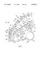
- FIG. 4is an elevational view of the FIG. 1 airbag installation, taken in the direction of arrow 4 in FIG. 1.
- FIG. 5is a fragmentary sectional view taken in the same direction as FIGS. 1 and 3, but illustrating a variant of the FIG. 3 construction.
- FIG. 1there is shown a vehicle safety airbag installation embodying the invention.
- the airbag installationis intended for deployment on the passenger side of the vehicle, not the driver side.
- the airbag installationincludes an instrument panel 10 and an airbag assembly 12 concealed by the instrument panel.
- Instrument panel 10includes an upper shelf portion 14, an intermediate angular portion 16, and a reinforced lower portion 18.
- the space located below the instrument panelis normally occupied by a glove compartment, not shown.
- the vehicle windshieldis located to the right of the instrument panel.
- the passenger spaceis located to the left of the instrument panel.
- Instrument panel 10includes a plastic skin 20, resilient foam core 22, and an inner flexible wall 24.
- Wall 24is preferably formed of sheet steel.
- Resilient foam core 22is adhesively bonded to skin 20 and flexible wall 24.
- Wall 24includes an upper portion 26 that turns downwardly away from foam core 22 for attachment to an internal support bracket 28.
- Wall 24has a lower front edge 30 that seats in a trough structure 32 formed on a retainer 34 that extends horizontally along the lower edge area of foam core 22.
- the foam coreis preferably bonded to retainer 34.
- a decorative trim strip 36can be attached to retainer 34 to conceal the lower edge of foam core 22.
- the internal surface of plastic skin 20has a notch 38 extending therealong.
- FIG. 1shows the notch in cross section.
- FIG. 4shows the planar configuration of the notch.
- the notchhas a U-shaped configuration, that includes a horizontal notch segment 40 extending along the lower portion of the instrument panel, and two upwardly extending notch segments 42 extending upwardly from notch segments 40.
- Notch segments 42terminate at, or near, the point where the instrument panel begins to ran horizontally, as at 14 in FIG. 1.
- Flexible wall 24has a lower edge 30 aligned substantially with notch segments 40 of notch 38, and two side edges 44 aligned substantially with notch segments 42 of the notch 38. Should skin 20 be severed along the notch 38 seam, the area of panel 16 circumscribed by notch 38 will form a hinged flap having a hinge axis located on area 26 of flexible wall 24.
- FIG. 2shows the flap swung upwardly to a position permitting a safety airbag to expand through the opening formed by the flap into the passenger compartment (to the left of the instrument panel).
- Foam core 22is relatively fragile, such as to offer only minimal resistance to formation of the hinged flap.
- the single hinged flapis devoid of slots or weakened points in surface area 82 (FIG. 1) where a passenger might likely strike the panel.
- Retainer 34is located below passenger impact area 82, such that area 82 can be optimized for cushioning performance.
- Airbag assembly 12comprises a rigid canister 50 that includes a cylindrical chamber 52 containing a gas generator (not shown), and a second chamber 53 containing a folded airbag 54.
- a gas generator(not shown)
- the airbagis expanded to the condition depicted generally in FIG. 2.
- Canister 50includes two end plates 56 having ears 58 for attaching the canister to support structures 28 and 34.
- the end platesconfine the expanding airbag against undesired lateral expansion.
- the spacing of end plates 56is slightly less than the spacing between side edges 44 of flexible wall 24 that define the side edges of the hinged flap.
- Canister 50has an airbag exit mouth registering with the flap formed by the U-shaped notch 38.
- a hinged closure means 60normally closes the exit mouth so as to prevent inadvertent escape of the folded airbag out of chamber 53.
- Closure means 60comprises an upper lid 62 having a hinged connection 70 with the canister, and a lower lid 66 having a hinged connection 71 with the canister. The free edges of lids 62 and 66 are joined together by a severable connection 69 that may be a notch or a series of perforations.
- the airbagpresses against lids 62 and 66 so as to sever the scored connection 69 between the lids.
- the lidsswing outwardly around the respective hinge connections 70 and 71, to forcibly strike wall 24.
- This actionsevers skin 20 and foam core 22 along the seam formed by U-shaped notch 38.
- the hinged flap formed by this severing actionswings upwardly to the FIG. 2 condition, permitting the airbag to expand into the passenger compartment.
- the closure means 60 for the canister exit mouthis initially installed on the canister by means of the hinge connections 70 and 71.
- Each hinge connectionincludes a cylindrical enlargement having a swivel fit in a mating socket formed on the canister wall.
- each cylindrical enlargementwill swivel slightly in the associated socket.
- the lidsare prevented from unlimited swinging motion by structures in the lid movement paths.
- Lid 62contacts wall 24, so that during the final stage of lid motion the lid swings in reverse fashion generally around a hinge 64 axis.
- Hinge axis 64forms a living hinge.
- Lid 66contacts the fixed stop structure 74 shortly after connection 69 is severed so that the lid flexes around the upper end of structure 74 from the FIG. 1 condition to the FIG. 2 condition.
- Hinge 68is a living hinge.
- the use of living hinges 64 and 68 for lids 62 and 66is believed to be advantageous in minimizing shock forces on the lid walls.
- the hinge structuresare designed to preclude obstructions or gaps at the edges of the canister mouth that could interfere with airbag deployment while the lids swing to the FIG. 2 open condition.
- lid 66when lid 66 is in the open position the lid extends across the upper edge of panel retainer 34 and trim strip 36.
- the lidthus acts as a guide for the airbag, to prevent the airbag from expanding into the gap 35 alongside retainer 34.
- Retainer 34 and stop structure 74provide support for the lid 66 and the associated lower wall of the canister (to prevent outward ballooning of the canister lower wall). If gap 35 were not closed by lid 66, the airbag could expand into the gap and cause damage to the panel retainer 34. In some cases, the panel retainer could actually splinter causing potential injury.
- the panel retainer 34By closing gap 35 with lid 66, the panel retainer 34 is cushioned from the force of the deploying airbag. This allows the panel retainer 34 to be constructed with a more compliant energy absorbing structure such that rigidifying and strengthening ribs on the panel reinforcement may be reduced or eliminated. This, in turn, provides a safer and softer surface to a passenger in the event of low energy impacts, which do not cause airbag deployment. In this case, if the passenger impacts the trim strip 36 and retainer 34, a softer and safer impact results.
- upper lid 62has a length dimension (from its hinge axis 64 to severable connection 69) that is substantially greater than the corresponding length dimension of lower lid 66. This is necessary in order to prevent lid 66 from having excessive area clamped under pressure to the flap wall 24, which may pull the lower lid 66 off, compromising its function described above.
- FIG. 1shows an alternate arrangement that provides a short lower lid 66 with a separate extension flap 76 that overlies lid 66 to provide the protection described.
- Lid 66 in the FIG. 3 constructionis shortened in proportion to the lengthening of lid 62.
- the lidis equipped with an auxiliary swingable extension arm 76 that overlies lid 66.
- arm 76has a free edge 78 that extends beyond severable connection 69 into overlapment with lid 62.
- Extension arm 76extends the effective length of lid 66 without extending the length of lid 66 itself creating the excessive clamped area that would compromise its function.
- FIG. 5shows another way of extending the free edge of lid 66 without unduly lengthening lid 66.
- lid 66has an extension arm 82 secured to its upper surface, such that arm 82 overlies lid 62 when the lids are closed. Extension arm 82 effectively extends the length of lid 66, while keeping the portion below connection 69 short.
- the instrument panelis constructed to form a single hinged flap, via the U-shaped notch 38.
- the single flapis rigidified by the retainer 34 located along the flap lower edge.
- the upper portion 82 of the flapis relatively resilient so as to be capable of absorbing low level impacts, e.g. should a person strike his head on the skin 22 surface without deployment of the airbag.
- lids 62 and 66are spaced from the internal surface of the instrument panel, such that the airbag assembly does not interfere with the cushioning action of the padded instrument panel. At the same time the lids 62 and 66 are close enough to the instrument panel to facilitate airbag deployment in a crash situation. Lids 62 and 66 act as guides for the airbag while the airbag is expanding out of the canister into the passenger compartment. As shown in FIG. 2, lower lid 66 spans the gap 35 between the airbag canister and retainer bar 34, to prelude undesired expansion of the airbag into the gap behind retainer 34.
Landscapes
- Engineering & Computer Science (AREA)
- Mechanical Engineering (AREA)
- Air Bags (AREA)
Abstract
Description
Claims (3)
Priority Applications (1)
| Application Number | Priority Date | Filing Date | Title |
|---|---|---|---|
| US09/208,201US6158763A (en) | 1998-12-09 | 1998-12-09 | Airbag assembly concealed within an instrument panel |
Applications Claiming Priority (1)
| Application Number | Priority Date | Filing Date | Title |
|---|---|---|---|
| US09/208,201US6158763A (en) | 1998-12-09 | 1998-12-09 | Airbag assembly concealed within an instrument panel |
Publications (1)
| Publication Number | Publication Date |
|---|---|
| US6158763Atrue US6158763A (en) | 2000-12-12 |
Family
ID=22773636
Family Applications (1)
| Application Number | Title | Priority Date | Filing Date |
|---|---|---|---|
| US09/208,201Expired - LifetimeUS6158763A (en) | 1998-12-09 | 1998-12-09 | Airbag assembly concealed within an instrument panel |
Country Status (1)
| Country | Link |
|---|---|
| US (1) | US6158763A (en) |
Cited By (27)
| Publication number | Priority date | Publication date | Assignee | Title |
|---|---|---|---|---|
| US6299198B1 (en)* | 1998-01-19 | 2001-10-09 | Sanko Gosei Kabushiki Kaisha | Passenger-side airbag system |
| US6364349B1 (en)* | 2001-04-20 | 2002-04-02 | Trw Vehicle Safety Systems Inc. | Inflatable curtain housing with deployment flap |
| US6390497B1 (en)* | 2000-09-01 | 2002-05-21 | Hyundai Motor Company | Airbag door of a vehicle |
| US20030030253A1 (en)* | 2001-08-07 | 2003-02-13 | Faurecia Industries | Air bag assembly for a motor vehicle |
| US20030071443A1 (en)* | 2000-04-27 | 2003-04-17 | Olaf Muller | Airbag device and method for operating an airbag device |
| US6631920B1 (en)* | 1999-02-18 | 2003-10-14 | Delphi Technologies, Inc. | Airbag module |
| EP1260417A3 (en)* | 2001-05-21 | 2004-02-04 | Toyoda Gosei Co., Ltd. | Knee protecting airbag device |
| US6835439B1 (en)* | 1997-07-23 | 2004-12-28 | Toyota Shatai Kabushiki Kaisha | Panel for air bags and method of manufacturing the same |
| US6851704B2 (en) | 2002-05-13 | 2005-02-08 | Lear Corporation | Air bag assembly |
| US20060012153A1 (en)* | 2000-12-08 | 2006-01-19 | Acts Advanced Car Technology Systems Gmbh & Co. Kg | Airbag system for motor vehicle integrated in an inner trim piece |
| US20060033313A1 (en)* | 2004-08-16 | 2006-02-16 | Moriroku Kabushiki Kaisha | Vehicle airbag system |
| US20060043701A1 (en)* | 2004-08-24 | 2006-03-02 | Visteon Global Technologies, Inc. | Hinge mechanism for inflatable restraint apparatus |
| US20060091650A1 (en)* | 2004-10-20 | 2006-05-04 | Calsonic Kansei Corporation | Airbag attachment structure, airbag system and vehicle including the same |
| US20070052210A1 (en)* | 2003-09-24 | 2007-03-08 | Faurecia Innenraum Systeme Gmbh | Interior trim part for covering an airbag |
| KR100727192B1 (en)* | 2001-02-22 | 2007-06-13 | 현대자동차주식회사 | Car airbag door |
| KR100735980B1 (en) | 2005-12-21 | 2007-07-06 | 현대모비스 주식회사 | Passenger airbag module |
| FR2899175A1 (en) | 2006-04-04 | 2007-10-05 | Faurecia Interieur Ind Snc | Foam type fascia for use with air bag in motor vehicle, has membrane including flexibility to bend around edge of opening to contact skin, and relationship between its mechanical resistance and friction coefficient with surface |
| WO2007128921A1 (en)* | 2006-05-09 | 2007-11-15 | Faurecia Interieur Industrie | Motor vehicle component and motor vehicle equipped with same |
| US20070278773A1 (en)* | 2006-06-04 | 2007-12-06 | Lear Corporation | Airbag Living Hinge Assembly |
| US7354060B2 (en)* | 2005-07-27 | 2008-04-08 | Gm Global Technology Operations, Inc. | Air bag module with low force cover opening |
| US20080203709A1 (en)* | 2007-02-06 | 2008-08-28 | Lisa Draxlmaier Gmbh | Directional device for deployment of an airbag |
| US20090194980A1 (en)* | 2008-01-31 | 2009-08-06 | Yuki Kobayashi | Airbag device |
| US20130147166A1 (en)* | 2010-05-11 | 2013-06-13 | Glenn A. Cowelchuk | Vehicle Interior Assembly |
| US20140203540A1 (en)* | 2011-09-01 | 2014-07-24 | Faurecia Interieur Industrie | Vehicle Safety Device |
| JP2014208512A (en)* | 2013-03-29 | 2014-11-06 | 豊田合成株式会社 | Airbag device for front passenger seat |
| GB2522751A (en)* | 2013-11-29 | 2015-08-05 | Nihon Plast Co Ltd | Case member of airbag device, airbag device, method of manufacturing airbag device, and apparatus for manufacturing airbag device |
| US20150266432A1 (en)* | 2014-03-24 | 2015-09-24 | Toyoda Gosei Co., Ltd. | Structure of terminal portion of product with cover |
Citations (20)
| Publication number | Priority date | Publication date | Assignee | Title |
|---|---|---|---|---|
| US3778085A (en)* | 1971-10-06 | 1973-12-11 | M Lipkin | Concealed pneumatic safety system |
| US4842300A (en)* | 1988-04-01 | 1989-06-27 | Trw Vehicle Safety Systems Inc. | Vehicle air bag module with internal reinforcing structure |
| US5013065A (en)* | 1988-11-01 | 1991-05-07 | Kolbenschmidt Aktiengesellschaft | Gas bag apparatus for protection against an impact |
| US5069480A (en)* | 1989-05-31 | 1991-12-03 | Allied-Signal Inc. | Air bag retainer assembly |
| US5135253A (en)* | 1989-05-24 | 1992-08-04 | Mazda Motor Corporation | Air bag system for vehicle |
| US5211421A (en)* | 1992-02-24 | 1993-05-18 | General Motors Corporation | Air bag cover door retainer |
| US5242192A (en)* | 1992-02-24 | 1993-09-07 | Morton International, Inc. | Fabric cover/chute for airbag modules |
| US5342087A (en)* | 1990-11-27 | 1994-08-30 | Mazda Motor Corporation | Air bag for vehicle safety device |
| US5375876A (en)* | 1993-10-05 | 1994-12-27 | Tip Engineering Group, Inc. | Air bag deployment door installation |
| US5378014A (en)* | 1992-11-13 | 1995-01-03 | Davidson Textron Inc. | Dual door arrangement for air bag deployment |
| US5407225A (en)* | 1993-08-19 | 1995-04-18 | Davidson Textron | Invisible airbag door having reinforced PVC shell |
| US5447329A (en)* | 1993-09-03 | 1995-09-05 | Ikeda Bussan Co., Ltd. | Air-bag device including protective sheet |
| US5451075A (en)* | 1994-06-29 | 1995-09-19 | Davidson Textron Inc. | Closure for an air bag assembly |
| US5582424A (en)* | 1994-01-21 | 1996-12-10 | Nissan Motor Co., Ltd. | Occupant restraint device |
| US5588674A (en)* | 1994-10-07 | 1996-12-31 | Isuzu Motors Limited | Intervening cloth on an air bag |
| US5613704A (en)* | 1996-04-22 | 1997-03-25 | Trw Vehicle Safety Systems Inc. | Diffuser structure for clamping an inflator in an air bag module |
| US5630614A (en)* | 1995-11-13 | 1997-05-20 | General Motors Corporation | Bias apparatus for air bag module |
| US5647608A (en)* | 1996-06-28 | 1997-07-15 | General Motors Corporation | Air bag module with extruded housing |
| US5863062A (en)* | 1996-07-19 | 1999-01-26 | Kabushiki Kaisha Inoac Corporation | Structure of air bag door of instrument panel |
| US5961142A (en)* | 1996-08-26 | 1999-10-05 | Kabushiki Kaisha Inoac Corporation | Instrument panel with air bag door |
- 1998
- 1998-12-09USUS09/208,201patent/US6158763A/ennot_activeExpired - Lifetime
Patent Citations (20)
| Publication number | Priority date | Publication date | Assignee | Title |
|---|---|---|---|---|
| US3778085A (en)* | 1971-10-06 | 1973-12-11 | M Lipkin | Concealed pneumatic safety system |
| US4842300A (en)* | 1988-04-01 | 1989-06-27 | Trw Vehicle Safety Systems Inc. | Vehicle air bag module with internal reinforcing structure |
| US5013065A (en)* | 1988-11-01 | 1991-05-07 | Kolbenschmidt Aktiengesellschaft | Gas bag apparatus for protection against an impact |
| US5135253A (en)* | 1989-05-24 | 1992-08-04 | Mazda Motor Corporation | Air bag system for vehicle |
| US5069480A (en)* | 1989-05-31 | 1991-12-03 | Allied-Signal Inc. | Air bag retainer assembly |
| US5342087A (en)* | 1990-11-27 | 1994-08-30 | Mazda Motor Corporation | Air bag for vehicle safety device |
| US5211421A (en)* | 1992-02-24 | 1993-05-18 | General Motors Corporation | Air bag cover door retainer |
| US5242192A (en)* | 1992-02-24 | 1993-09-07 | Morton International, Inc. | Fabric cover/chute for airbag modules |
| US5378014A (en)* | 1992-11-13 | 1995-01-03 | Davidson Textron Inc. | Dual door arrangement for air bag deployment |
| US5407225A (en)* | 1993-08-19 | 1995-04-18 | Davidson Textron | Invisible airbag door having reinforced PVC shell |
| US5447329A (en)* | 1993-09-03 | 1995-09-05 | Ikeda Bussan Co., Ltd. | Air-bag device including protective sheet |
| US5375876A (en)* | 1993-10-05 | 1994-12-27 | Tip Engineering Group, Inc. | Air bag deployment door installation |
| US5582424A (en)* | 1994-01-21 | 1996-12-10 | Nissan Motor Co., Ltd. | Occupant restraint device |
| US5451075A (en)* | 1994-06-29 | 1995-09-19 | Davidson Textron Inc. | Closure for an air bag assembly |
| US5588674A (en)* | 1994-10-07 | 1996-12-31 | Isuzu Motors Limited | Intervening cloth on an air bag |
| US5630614A (en)* | 1995-11-13 | 1997-05-20 | General Motors Corporation | Bias apparatus for air bag module |
| US5613704A (en)* | 1996-04-22 | 1997-03-25 | Trw Vehicle Safety Systems Inc. | Diffuser structure for clamping an inflator in an air bag module |
| US5647608A (en)* | 1996-06-28 | 1997-07-15 | General Motors Corporation | Air bag module with extruded housing |
| US5863062A (en)* | 1996-07-19 | 1999-01-26 | Kabushiki Kaisha Inoac Corporation | Structure of air bag door of instrument panel |
| US5961142A (en)* | 1996-08-26 | 1999-10-05 | Kabushiki Kaisha Inoac Corporation | Instrument panel with air bag door |
Cited By (42)
| Publication number | Priority date | Publication date | Assignee | Title |
|---|---|---|---|---|
| US6835439B1 (en)* | 1997-07-23 | 2004-12-28 | Toyota Shatai Kabushiki Kaisha | Panel for air bags and method of manufacturing the same |
| US6299198B1 (en)* | 1998-01-19 | 2001-10-09 | Sanko Gosei Kabushiki Kaisha | Passenger-side airbag system |
| US6631920B1 (en)* | 1999-02-18 | 2003-10-14 | Delphi Technologies, Inc. | Airbag module |
| US20030071443A1 (en)* | 2000-04-27 | 2003-04-17 | Olaf Muller | Airbag device and method for operating an airbag device |
| US6733033B2 (en)* | 2000-04-27 | 2004-05-11 | Volkswagen Ag | Airbag device and method for operating an airbag device |
| US6390497B1 (en)* | 2000-09-01 | 2002-05-21 | Hyundai Motor Company | Airbag door of a vehicle |
| US20060012153A1 (en)* | 2000-12-08 | 2006-01-19 | Acts Advanced Car Technology Systems Gmbh & Co. Kg | Airbag system for motor vehicle integrated in an inner trim piece |
| KR100727192B1 (en)* | 2001-02-22 | 2007-06-13 | 현대자동차주식회사 | Car airbag door |
| US6364349B1 (en)* | 2001-04-20 | 2002-04-02 | Trw Vehicle Safety Systems Inc. | Inflatable curtain housing with deployment flap |
| EP1260417A3 (en)* | 2001-05-21 | 2004-02-04 | Toyoda Gosei Co., Ltd. | Knee protecting airbag device |
| US20030030253A1 (en)* | 2001-08-07 | 2003-02-13 | Faurecia Industries | Air bag assembly for a motor vehicle |
| US6817627B2 (en)* | 2001-08-07 | 2004-11-16 | Faurecia Industries | Air bag assembly for a motor vehicle |
| US6851704B2 (en) | 2002-05-13 | 2005-02-08 | Lear Corporation | Air bag assembly |
| US20070052210A1 (en)* | 2003-09-24 | 2007-03-08 | Faurecia Innenraum Systeme Gmbh | Interior trim part for covering an airbag |
| US7611163B2 (en)* | 2003-09-24 | 2009-11-03 | Faurecia Innenraum Systeme Gmbh | Interior trim part for covering an airbag |
| US20060033313A1 (en)* | 2004-08-16 | 2006-02-16 | Moriroku Kabushiki Kaisha | Vehicle airbag system |
| US20060043701A1 (en)* | 2004-08-24 | 2006-03-02 | Visteon Global Technologies, Inc. | Hinge mechanism for inflatable restraint apparatus |
| US7210700B2 (en) | 2004-08-24 | 2007-05-01 | Visteon Global Technologies, Inc | Hinge mechanism for inflatable restraint apparatus |
| US20060091650A1 (en)* | 2004-10-20 | 2006-05-04 | Calsonic Kansei Corporation | Airbag attachment structure, airbag system and vehicle including the same |
| US7354060B2 (en)* | 2005-07-27 | 2008-04-08 | Gm Global Technology Operations, Inc. | Air bag module with low force cover opening |
| KR100735980B1 (en) | 2005-12-21 | 2007-07-06 | 현대모비스 주식회사 | Passenger airbag module |
| WO2007118991A1 (en)* | 2006-04-04 | 2007-10-25 | Faurecia Interieur Industrie | Motor vehicle instrument panel equipped with an airbag |
| FR2899175A1 (en) | 2006-04-04 | 2007-10-05 | Faurecia Interieur Ind Snc | Foam type fascia for use with air bag in motor vehicle, has membrane including flexibility to bend around edge of opening to contact skin, and relationship between its mechanical resistance and friction coefficient with surface |
| FR2900890A1 (en)* | 2006-05-09 | 2007-11-16 | Faurecia Interieur Ind Snc | EQUIPMENT PIECE FOR MOTOR VEHICLE AND ASSOCIATED MOTOR VEHICLE |
| WO2007128921A1 (en)* | 2006-05-09 | 2007-11-15 | Faurecia Interieur Industrie | Motor vehicle component and motor vehicle equipped with same |
| US20070278773A1 (en)* | 2006-06-04 | 2007-12-06 | Lear Corporation | Airbag Living Hinge Assembly |
| US20080203709A1 (en)* | 2007-02-06 | 2008-08-28 | Lisa Draxlmaier Gmbh | Directional device for deployment of an airbag |
| US8181986B2 (en)* | 2007-02-06 | 2012-05-22 | Lisa Dräxlmaier GmbH | Directional device for deployment of an airbag |
| US20090194980A1 (en)* | 2008-01-31 | 2009-08-06 | Yuki Kobayashi | Airbag device |
| US7900955B2 (en)* | 2008-01-31 | 2011-03-08 | Honda Motor Co., Ltd. | Airbag device |
| US8794661B2 (en)* | 2010-05-11 | 2014-08-05 | Johnson Controls Technology Company | Vehicle interior assembly |
| US20130147166A1 (en)* | 2010-05-11 | 2013-06-13 | Glenn A. Cowelchuk | Vehicle Interior Assembly |
| US20140203540A1 (en)* | 2011-09-01 | 2014-07-24 | Faurecia Interieur Industrie | Vehicle Safety Device |
| US9156428B2 (en)* | 2011-09-01 | 2015-10-13 | Faurecia Interieur Industrie | Vehicle safety device |
| JP2014208512A (en)* | 2013-03-29 | 2014-11-06 | 豊田合成株式会社 | Airbag device for front passenger seat |
| GB2522751A (en)* | 2013-11-29 | 2015-08-05 | Nihon Plast Co Ltd | Case member of airbag device, airbag device, method of manufacturing airbag device, and apparatus for manufacturing airbag device |
| US9421936B2 (en) | 2013-11-29 | 2016-08-23 | Nihon Plast Co., Ltd. | Case member of airbag device, airbag device, method of manufacturing airbag device, and apparatus for manufacturing airbag device |
| GB2522751B (en)* | 2013-11-29 | 2020-02-19 | Nihon Plast Co Ltd | Case member of airbag device, airbag device, method of manufacturing airbag device, and apparatus for manufacturing airbag device |
| US20150266432A1 (en)* | 2014-03-24 | 2015-09-24 | Toyoda Gosei Co., Ltd. | Structure of terminal portion of product with cover |
| CN104943621A (en)* | 2014-03-24 | 2015-09-30 | 丰田合成株式会社 | Structure of terminal portion of product with cover |
| US9266480B2 (en)* | 2014-03-24 | 2016-02-23 | Toyoda Gosei Co., Ltd. | Structure of terminal portion of product with cover |
| CN104943621B (en)* | 2014-03-24 | 2017-04-12 | 丰田合成株式会社 | Structure of terminal portion of product with cover |
Similar Documents
| Publication | Publication Date | Title |
|---|---|---|
| US6158763A (en) | Airbag assembly concealed within an instrument panel | |
| US5470103A (en) | Motor vehicle head impact air bag system | |
| JP3735622B2 (en) | Deployment door structure with a hidden seam, with a stabilized airbag deployment opening | |
| JP2860286B2 (en) | Gas bag protector for lateral impact | |
| US8177256B2 (en) | Vehicle seat having an integrated airbag module | |
| KR940010716B1 (en) | Car air bag device | |
| JP3717124B2 (en) | Air bag | |
| JP3321531B2 (en) | Instrument panel with airbag door | |
| US5280947A (en) | One piece invisible airbag door and hinge | |
| JPH10203294A (en) | Seamless side expansion type constraint development system | |
| JP2001088646A (en) | Air bag door structure | |
| JP2004338708A (en) | Seat-integrated vehicle occupant restraint system and vehicle seat | |
| US6286858B1 (en) | Energy absorbing air bag module | |
| EP0710591B1 (en) | Seamless door for air bag module | |
| JP3778498B2 (en) | Vehicle occupant protection device | |
| US20070182131A1 (en) | Housing for an airbag device | |
| US6328333B1 (en) | Pillar trim for inflatable restraint system | |
| US6007089A (en) | Passenger restraint system for the backseat of a vehicle | |
| US5306040A (en) | Cover for airbag | |
| GB2440022A (en) | Instrument panel allowing airbag deployment | |
| US7547040B2 (en) | Side impact protective apparatus for a motor vehicle occupant | |
| JP3405246B2 (en) | Installation structure of vehicle occupant protection system | |
| CN1154311A (en) | Air cover used for assistant person | |
| JP3385905B2 (en) | Installation structure of vehicle occupant protection system | |
| JP3805862B2 (en) | Airbag device |
Legal Events
| Date | Code | Title | Description |
|---|---|---|---|
| AS | Assignment | Owner name:CHRYSLER CORPORATION, MICHIGAN Free format text:ASSIGNMENT OF ASSIGNORS INTEREST;ASSIGNORS:DOMINIQUE, ALEXANDER L.;BITTINGER, D. SCOTT;NASSER, ISSA A.;AND OTHERS;REEL/FRAME:009750/0389;SIGNING DATES FROM 19981116 TO 19981203 | |
| STCF | Information on status: patent grant | Free format text:PATENTED CASE | |
| FPAY | Fee payment | Year of fee payment:4 | |
| AS | Assignment | Owner name:WILMINGTON TRUST COMPANY, DELAWARE Free format text:GRANT OF SECURITY INTEREST IN PATENT RIGHTS - FIRST PRIORITY;ASSIGNOR:CHRYSLER LLC;REEL/FRAME:019773/0001 Effective date:20070803 Owner name:WILMINGTON TRUST COMPANY,DELAWARE Free format text:GRANT OF SECURITY INTEREST IN PATENT RIGHTS - FIRST PRIORITY;ASSIGNOR:CHRYSLER LLC;REEL/FRAME:019773/0001 Effective date:20070803 | |
| AS | Assignment | Owner name:WILMINGTON TRUST COMPANY, DELAWARE Free format text:GRANT OF SECURITY INTEREST IN PATENT RIGHTS - SECOND PRIORITY;ASSIGNOR:CHRYSLER LLC;REEL/FRAME:019767/0810 Effective date:20070803 Owner name:WILMINGTON TRUST COMPANY,DELAWARE Free format text:GRANT OF SECURITY INTEREST IN PATENT RIGHTS - SECOND PRIORITY;ASSIGNOR:CHRYSLER LLC;REEL/FRAME:019767/0810 Effective date:20070803 | |
| FPAY | Fee payment | Year of fee payment:8 | |
| AS | Assignment | Owner name:DAIMLERCHRYSLER CORPORATION, MICHIGAN Free format text:CHANGE OF NAME;ASSIGNOR:CHRYSLER CORPORATION;REEL/FRAME:021826/0034 Effective date:19981116 | |
| AS | Assignment | Owner name:CHRYSLER LLC, MICHIGAN Free format text:CHANGE OF NAME;ASSIGNOR:DAIMLERCHRYSLER COMPANY LLC;REEL/FRAME:021832/0233 Effective date:20070727 Owner name:DAIMLERCHRYSLER COMPANY LLC, MICHIGAN Free format text:CHANGE OF NAME;ASSIGNOR:DAIMLERCHRYSLER CORPORATION;REEL/FRAME:021832/0256 Effective date:20070329 | |
| AS | Assignment | Owner name:US DEPARTMENT OF THE TREASURY, DISTRICT OF COLUMBI Free format text:GRANT OF SECURITY INTEREST IN PATENT RIGHTS - THIR;ASSIGNOR:CHRYSLER LLC;REEL/FRAME:022259/0188 Effective date:20090102 Owner name:US DEPARTMENT OF THE TREASURY,DISTRICT OF COLUMBIA Free format text:GRANT OF SECURITY INTEREST IN PATENT RIGHTS - THIR;ASSIGNOR:CHRYSLER LLC;REEL/FRAME:022259/0188 Effective date:20090102 | |
| AS | Assignment | Owner name:CHRYSLER LLC, MICHIGAN Free format text:RELEASE BY SECURED PARTY;ASSIGNOR:US DEPARTMENT OF THE TREASURY;REEL/FRAME:022910/0273 Effective date:20090608 | |
| AS | Assignment | Owner name:CHRYSLER LLC, MICHIGAN Free format text:RELEASE OF SECURITY INTEREST IN PATENT RIGHTS - FIRST PRIORITY;ASSIGNOR:WILMINGTON TRUST COMPANY;REEL/FRAME:022910/0498 Effective date:20090604 Owner name:CHRYSLER LLC, MICHIGAN Free format text:RELEASE OF SECURITY INTEREST IN PATENT RIGHTS - SECOND PRIORITY;ASSIGNOR:WILMINGTON TRUST COMPANY;REEL/FRAME:022910/0740 Effective date:20090604 Owner name:NEW CARCO ACQUISITION LLC, MICHIGAN Free format text:ASSIGNMENT OF ASSIGNORS INTEREST;ASSIGNOR:CHRYSLER LLC;REEL/FRAME:022915/0001 Effective date:20090610 Owner name:THE UNITED STATES DEPARTMENT OF THE TREASURY, DIST Free format text:SECURITY AGREEMENT;ASSIGNOR:NEW CARCO ACQUISITION LLC;REEL/FRAME:022915/0489 Effective date:20090610 Owner name:CHRYSLER LLC,MICHIGAN Free format text:RELEASE OF SECURITY INTEREST IN PATENT RIGHTS - FIRST PRIORITY;ASSIGNOR:WILMINGTON TRUST COMPANY;REEL/FRAME:022910/0498 Effective date:20090604 Owner name:CHRYSLER LLC,MICHIGAN Free format text:RELEASE OF SECURITY INTEREST IN PATENT RIGHTS - SECOND PRIORITY;ASSIGNOR:WILMINGTON TRUST COMPANY;REEL/FRAME:022910/0740 Effective date:20090604 Owner name:NEW CARCO ACQUISITION LLC,MICHIGAN Free format text:ASSIGNMENT OF ASSIGNORS INTEREST;ASSIGNOR:CHRYSLER LLC;REEL/FRAME:022915/0001 Effective date:20090610 Owner name:THE UNITED STATES DEPARTMENT OF THE TREASURY,DISTR Free format text:SECURITY AGREEMENT;ASSIGNOR:NEW CARCO ACQUISITION LLC;REEL/FRAME:022915/0489 Effective date:20090610 | |
| AS | Assignment | Owner name:CHRYSLER GROUP LLC, MICHIGAN Free format text:CHANGE OF NAME;ASSIGNOR:NEW CARCO ACQUISITION LLC;REEL/FRAME:022919/0126 Effective date:20090610 Owner name:CHRYSLER GROUP LLC,MICHIGAN Free format text:CHANGE OF NAME;ASSIGNOR:NEW CARCO ACQUISITION LLC;REEL/FRAME:022919/0126 Effective date:20090610 | |
| AS | Assignment | Owner name:CHRYSLER GROUP GLOBAL ELECTRIC MOTORCARS LLC, NORT Free format text:RELEASE BY SECURED PARTY;ASSIGNOR:THE UNITED STATES DEPARTMENT OF THE TREASURY;REEL/FRAME:026343/0298 Effective date:20110524 Owner name:CHRYSLER GROUP LLC, MICHIGAN Free format text:RELEASE BY SECURED PARTY;ASSIGNOR:THE UNITED STATES DEPARTMENT OF THE TREASURY;REEL/FRAME:026343/0298 Effective date:20110524 | |
| AS | Assignment | Owner name:CITIBANK, N.A., NEW YORK Free format text:SECURITY AGREEMENT;ASSIGNOR:CHRYSLER GROUP LLC;REEL/FRAME:026404/0123 Effective date:20110524 | |
| AS | Assignment | Owner name:CITIBANK, N.A., NEW YORK Free format text:SECURITY AGREEMENT;ASSIGNOR:CHRYSLER GROUP LLC;REEL/FRAME:026435/0652 Effective date:20110524 | |
| FPAY | Fee payment | Year of fee payment:12 | |
| AS | Assignment | Owner name:JPMORGAN CHASE BANK, N.A., ILLINOIS Free format text:SECURITY AGREEMENT;ASSIGNOR:CHRYSLER GROUP LLC;REEL/FRAME:032384/0640 Effective date:20140207 | |
| AS | Assignment | Owner name:FCA US LLC, MICHIGAN Free format text:CHANGE OF NAME;ASSIGNOR:CHRYSLER GROUP LLC;REEL/FRAME:035553/0356 Effective date:20141203 | |
| AS | Assignment | Owner name:FCA US LLC, FORMERLY KNOWN AS CHRYSLER GROUP LLC, Free format text:RELEASE OF SECURITY INTEREST RELEASING SECOND-LIEN SECURITY INTEREST PREVIOUSLY RECORDED AT REEL 026426 AND FRAME 0644, REEL 026435 AND FRAME 0652, AND REEL 032384 AND FRAME 0591;ASSIGNOR:CITIBANK, N.A.;REEL/FRAME:037784/0001 Effective date:20151221 | |
| AS | Assignment | Owner name:FCA US LLC (FORMERLY KNOWN AS CHRYSLER GROUP LLC), Free format text:RELEASE BY SECURED PARTY;ASSIGNOR:CITIBANK, N.A.;REEL/FRAME:042885/0255 Effective date:20170224 | |
| AS | Assignment | Owner name:FCA US LLC (FORMERLY KNOWN AS CHRYSLER GROUP LLC), Free format text:RELEASE BY SECURED PARTY;ASSIGNOR:JPMORGAN CHASE BANK, N.A.;REEL/FRAME:048177/0356 Effective date:20181113 |