US6158652A - Container with wall locking feature - Google Patents
Container with wall locking featureDownload PDFInfo
- Publication number
- US6158652A US6158652AUS09/373,557US37355799AUS6158652AUS 6158652 AUS6158652 AUS 6158652AUS 37355799 AUS37355799 AUS 37355799AUS 6158652 AUS6158652 AUS 6158652A
- Authority
- US
- United States
- Prior art keywords
- panel
- panels
- sidewall
- wall
- wall panels
- Prior art date
- Legal status (The legal status is an assumption and is not a legal conclusion. Google has not performed a legal analysis and makes no representation as to the accuracy of the status listed.)
- Expired - Lifetime
Links
- 230000000295complement effectEffects0.000claimsabstractdescription16
- 210000002105tongueAnatomy0.000claimsdescription16
- 238000000034methodMethods0.000claimsdescription13
- 230000008878couplingEffects0.000claims2
- 238000010168coupling processMethods0.000claims2
- 238000005859coupling reactionMethods0.000claims2
- 238000009423ventilationMethods0.000abstractdescription5
- 239000010410layerSubstances0.000description11
- 239000000463materialSubstances0.000description10
- 239000011094fiberboardSubstances0.000description7
- 125000006850spacer groupChemical group0.000description7
- 230000013011matingEffects0.000description5
- 239000002365multiple layerSubstances0.000description5
- 230000015572biosynthetic processEffects0.000description3
- 239000003292glueSubstances0.000description3
- 238000004806packaging method and processMethods0.000description3
- 238000000926separation methodMethods0.000description3
- 239000000853adhesiveSubstances0.000description2
- 230000001070adhesive effectEffects0.000description2
- 230000008901benefitEffects0.000description2
- 238000003780insertionMethods0.000description2
- 230000037431insertionEffects0.000description2
- 230000002411adverseEffects0.000description1
- 230000008859changeEffects0.000description1
- 238000010276constructionMethods0.000description1
- 239000012611container materialSubstances0.000description1
- 239000011096corrugated fiberboardSubstances0.000description1
- 230000003247decreasing effectEffects0.000description1
- 238000013461designMethods0.000description1
- 230000001747exhibiting effectEffects0.000description1
- 238000012986modificationMethods0.000description1
- 230000004048modificationEffects0.000description1
- 230000037361pathwayEffects0.000description1
- 229920003023plasticPolymers0.000description1
- 239000004033plasticSubstances0.000description1
- 230000008569processEffects0.000description1
- 230000002035prolonged effectEffects0.000description1
- 230000002441reversible effectEffects0.000description1
- 238000012552reviewMethods0.000description1
- 239000000565sealantSubstances0.000description1
Images


Classifications
- B—PERFORMING OPERATIONS; TRANSPORTING
- B65—CONVEYING; PACKING; STORING; HANDLING THIN OR FILAMENTARY MATERIAL
- B65D—CONTAINERS FOR STORAGE OR TRANSPORT OF ARTICLES OR MATERIALS, e.g. BAGS, BARRELS, BOTTLES, BOXES, CANS, CARTONS, CRATES, DRUMS, JARS, TANKS, HOPPERS, FORWARDING CONTAINERS; ACCESSORIES, CLOSURES, OR FITTINGS THEREFOR; PACKAGING ELEMENTS; PACKAGES
- B65D5/00—Rigid or semi-rigid containers of polygonal cross-section, e.g. boxes, cartons or trays, formed by folding or erecting one or more blanks made of paper
- B65D5/001—Rigid or semi-rigid containers of polygonal cross-section, e.g. boxes, cartons or trays, formed by folding or erecting one or more blanks made of paper stackable
- B65D5/0015—Rigid or semi-rigid containers of polygonal cross-section, e.g. boxes, cartons or trays, formed by folding or erecting one or more blanks made of paper stackable the container being formed by folding up portions connected to a central panel
- B65D5/003—Rigid or semi-rigid containers of polygonal cross-section, e.g. boxes, cartons or trays, formed by folding or erecting one or more blanks made of paper stackable the container being formed by folding up portions connected to a central panel having ledges formed by extensions of the side walls
- B—PERFORMING OPERATIONS; TRANSPORTING
- B65—CONVEYING; PACKING; STORING; HANDLING THIN OR FILAMENTARY MATERIAL
- B65D—CONTAINERS FOR STORAGE OR TRANSPORT OF ARTICLES OR MATERIALS, e.g. BAGS, BARRELS, BOTTLES, BOXES, CANS, CARTONS, CRATES, DRUMS, JARS, TANKS, HOPPERS, FORWARDING CONTAINERS; ACCESSORIES, CLOSURES, OR FITTINGS THEREFOR; PACKAGING ELEMENTS; PACKAGES
- B65D5/00—Rigid or semi-rigid containers of polygonal cross-section, e.g. boxes, cartons or trays, formed by folding or erecting one or more blanks made of paper
- B65D5/20—Rigid or semi-rigid containers of polygonal cross-section, e.g. boxes, cartons or trays, formed by folding or erecting one or more blanks made of paper by folding-up portions connected to a central panel from all sides to form a container body, e.g. of tray-like form
- B65D5/22—Rigid or semi-rigid containers of polygonal cross-section, e.g. boxes, cartons or trays, formed by folding or erecting one or more blanks made of paper by folding-up portions connected to a central panel from all sides to form a container body, e.g. of tray-like form held erect by extensions of one or more sides being doubled-over to enclose extensions of adjacent sides
- B—PERFORMING OPERATIONS; TRANSPORTING
- B65—CONVEYING; PACKING; STORING; HANDLING THIN OR FILAMENTARY MATERIAL
- B65D—CONTAINERS FOR STORAGE OR TRANSPORT OF ARTICLES OR MATERIALS, e.g. BAGS, BARRELS, BOTTLES, BOXES, CANS, CARTONS, CRATES, DRUMS, JARS, TANKS, HOPPERS, FORWARDING CONTAINERS; ACCESSORIES, CLOSURES, OR FITTINGS THEREFOR; PACKAGING ELEMENTS; PACKAGES
- B65D5/00—Rigid or semi-rigid containers of polygonal cross-section, e.g. boxes, cartons or trays, formed by folding or erecting one or more blanks made of paper
- B65D5/20—Rigid or semi-rigid containers of polygonal cross-section, e.g. boxes, cartons or trays, formed by folding or erecting one or more blanks made of paper by folding-up portions connected to a central panel from all sides to form a container body, e.g. of tray-like form
- B65D5/26—Rigid or semi-rigid containers of polygonal cross-section, e.g. boxes, cartons or trays, formed by folding or erecting one or more blanks made of paper by folding-up portions connected to a central panel from all sides to form a container body, e.g. of tray-like form with extensions of opposite sides mutually interlocking to lie against other sides
- B—PERFORMING OPERATIONS; TRANSPORTING
- B65—CONVEYING; PACKING; STORING; HANDLING THIN OR FILAMENTARY MATERIAL
- B65D—CONTAINERS FOR STORAGE OR TRANSPORT OF ARTICLES OR MATERIALS, e.g. BAGS, BARRELS, BOTTLES, BOXES, CANS, CARTONS, CRATES, DRUMS, JARS, TANKS, HOPPERS, FORWARDING CONTAINERS; ACCESSORIES, CLOSURES, OR FITTINGS THEREFOR; PACKAGING ELEMENTS; PACKAGES
- B65D5/00—Rigid or semi-rigid containers of polygonal cross-section, e.g. boxes, cartons or trays, formed by folding or erecting one or more blanks made of paper
- B65D5/42—Details of containers or of foldable or erectable container blanks
- B65D5/4295—Ventilating arrangements, e.g. openings, space elements
- Y—GENERAL TAGGING OF NEW TECHNOLOGICAL DEVELOPMENTS; GENERAL TAGGING OF CROSS-SECTIONAL TECHNOLOGIES SPANNING OVER SEVERAL SECTIONS OF THE IPC; TECHNICAL SUBJECTS COVERED BY FORMER USPC CROSS-REFERENCE ART COLLECTIONS [XRACs] AND DIGESTS
- Y10—TECHNICAL SUBJECTS COVERED BY FORMER USPC
- Y10S—TECHNICAL SUBJECTS COVERED BY FORMER USPC CROSS-REFERENCE ART COLLECTIONS [XRACs] AND DIGESTS
- Y10S229/00—Envelopes, wrappers, and paperboard boxes
- Y10S229/915—Stacking feature
- Y10S229/919—Reinforced wall
Definitions
- the present inventionrelates to the field of storage containers. More particularly, the present invention relates to storage containers of the fiberboard type that are frequently used for the storage and transport of produce.
- the containerhas a floor, a first and second set of sidewalls and a lid.
- Each sidewall of the first set of sidewallsis further equipped with a pair of minor flap emanating from the lateral edges of the first sidewall.
- the pair of minor flapsare folded inwards until are adjacent to the pair of minor flaps of the opposing first sidewall.
- the second set of sidewallsare then folded upwards until they are flush with the minor flaps.
- the second set of sidewallsare then folded downwards to effectively "sandwich" the minor flaps within the second set of sidewalls.
- One drawback of this arrangementis that the floor can still sag or collapse.
- Some prior art containersinclude minor flaps that are long enough to allow the free edges of the flaps to overlap.
- this arrangementhas drawbacks as well. For example, the overlap between flaps requires the use of extra material which raises costs. Additionally, it also reduces the contact area between the second pair of sidewalls and the flaps, generally making the structure weaker. Accordingly, a more reliable container was needed.
- a containerincluding a floor, and a first and second pair of sidewalls extending upwards from the floor.
- the second pair of sidewallseach include an inner panel facing the inside of the container and forming an inner surface, an outer panel facing the outside of the container and forming an outer surface and a first and second interlocked wall panels.
- the first and second interlocked wall panelsare lockingly engaged with each other in a coplanar arrangement.
- the pair of interlocked wall panelslie between the outer panel and the inner panel of its respective sidewalls.
- a containercomprising a floor, a first pair of opposing sidewalls extending upwards from the floor and a second pair of sidewalls extending upwards from the floor.
- Each of the second pair of sidewallsis multi-layered and includes an inner panel forming an inner surface, an outer panel forming an outer surface and a first, second, third, and fourth interlocked wall panels.
- the first and second interlocked wall panelsare lockingly engaged with each other, as are the third and fourth interlocked wall panels.
- the first and second interlocked wall panelsare disposed in back-to-back, flush contact with the third and fourth interlocked wall panels forming a dual-lock arrangement. All four interlocked wall panels are, in turn, disposed between their respective inner and outer panels.
- a blank for forming the containerwhich includes a floor panel, a first, second, third and fourth opposing sidewall panels and a first, second, third and fourth opposing wall panels.
- the first and second opposing sidewall panelseach connect to the floor panel along a respective first and second foldlines and become the first pair of sidewalls in the finished container.
- the third and fourth opposing sidewall panelseach connect to the floor panel along respective third and fourth foldlines and become part of the second pair of sidewalls in the finished container.
- the third and fourth sidewall panelseach include a first segment panel connected along a foldline to the floor panel and a second panel segment coupled to the first panel segment.
- the first and second opposing wall panelseach have a proximal end coupled to the first opposing sidewall panel and a distal end which includes a first planar locking contour.
- the third and fourth opposing wall panelseach have a proximal end coupled to the second opposing sidewall and a distal end including a second planar locking contour.
- the second planar locking contouris complementary to the first planar locking contour and allows the adjacent wall panels to be lockingly connected when constructing the container.
- this blankin a fourth aspect of the invention is another blank for forming a container, this blank includes a floor panel, a first, second, third and fourth opposing sidewall panels and a first through eighth opposing wall panels.
- the first and second opposing sidewall panelsare each connected to the floor panel along a first and second foldlines, respectively, and become the first pair of opposing sidewalls in the erected container.
- each of the panelsis connected to the floor panel along a third and a fourth foldline, respectively.
- the third and fourth opposing sidewall panelseach have a first panel segment connected along a foldline to the floor panel, and a second panel segment coupled to the first panel segment.
- the first panel segmentbecomes the outer panel of the completed container, while the second panel segment becomes the inner panel of the completed container.
- the first and second opposing wall panelseach have a proximal end coupled to the first opposing sidewall panel and a distal end which includes a first locking contour.
- the third and fourth opposing wall panelsalso have a proximal end coupled to the second opposing sidewall and a distal end including a second locking contour. This second locking contour is complementary in shape to the first locking contour and allows their respective panels to be lockingly engaged when constructing the container.
- the fifth wall panelis coupled to the first wall panel and the sixth wall panel is coupled to the second wall panel.
- the fifth and sixth wall panelseach have a distal end with a third locking contour.
- the seventh wall panelis coupled to the third wall panel and the eighth wall panel is coupled to the fourth wall panel.
- the seventh and eight wall panelseach have a distal end which includes a fourth locking contour.
- the fourth locking contouris complementary in shape to the third locking contour and the locking contours allow their respective panels to be lockingly engaged to form the dual-lock arrangement of the completed container.
- a method of constructing the containercomprising several steps.
- the first stepis providing a blank having a floor panel, a first, second, third, and fourth opposing sidewall panels and a first, second, third and fourth wall panels.
- the first and second opposing sidewall panelsare folded upwardly along a pair of foldlines connecting the first and second opposing sidewall panels to the floor panel. This completes the first pair of opposing sidewalls.
- the first, second, third, and fourth wall panelsare folded inwardly along foldlines connecting them to the first pair of opposing sidewalls.
- the first and third wall panelsare lockingly engaged in a coplanar arrangement to form a first pair of interlocked wall panels.
- the second and fourth wall panelsare also lockingly engaged in a coplanar arrangement to form a second pair of interlocked wall panels.
- the third and fourth sidewall panelsare folded upwardly along a pair of foldlines connecting them to the floor panel to form a pair of outer panels.
- the same panelsare then folded downwards and inwards until flush with their respective interlocked wall panels to form a pair of inner panels. This step completes the second pair of opposing sidewalls.
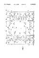
- FIG. 1is a plan view of the scored and cut blank for constructing the dual-lock container.
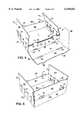
- FIG. 2is a perspective view of the blank in FIG. 1 being folded in a first intermediate state of assembly to form a first pair of opposing sidewalls.
- FIG. 3is a perspective view of the blank in FIG. 1 in a second intermediate state of assembly with segments being interlocked to form segment pairs.
- FIG. 4is a perspective view of the blank in FIG. 1 in a third intermediate state of assembly showing the segment pairs of FIG. 3 overlapped in an accordion arrangement to form a dual-lock configuration.
- FIG. 5is another perspective view of the blank in FIG. 1 in a fourth intermediate state of assembly showing the dual-locked segment pairs being enveloped by the inner and outer panels.
- FIG. 6is a perspective view of the blank in FIG. 1 formed into the completed container with the lid flaps in an open position.
- FIG. 7is a perspective view of the container of FIG. 6 with the lid flaps in a closed position.
- FIG. 8is a detailed perspective cut-out view of the second pair of opposing sidewalls exhibiting the dual-lock characteristic of overlapping segment pairs.
- FIGS. 6 and 7show a preferred embodiment of the fully constructed box or container 1.
- container 1includes a generally horizontal floor 3, a first pair of opposing vertical sidewalls 5, a second pair of opposing vertical sidewalls 7, and a pair of covers or lids 9.
- the lids 9are shown in a closed position in FIG. 7 and in an open position in FIG. 6. All of the aforementioned parts are interconnected to provide a structurally sound container that resists buckling when floor 3 is heavily loaded.
- the floor 3supports any contents within the container 1, such as produce.
- the floor 3is attached to the first pair of opposing sidewalls 5 through a foldline 45.
- the floor 3is also connected to the second pair of opposing sidewalls through a foldline 33.
- the first and second pairs of sidewalls 5 and 7are at right angles to each other.
- first pair of sidewalls 5 and panels extending in that same directionwill be referred to as being lateral or laterally oriented.
- second pair of sidewalls 7 and panels extending in that same directionwill be referred to as being longitudinal or longitudinally oriented.
- Blank 25is cut and scored into several panels that may be erected into container 1.
- Blank 25preferably includes a rectangular floor panel I that is the floor 3 of the container 1.
- Opposing longitudinal panels A and Bextend longitudinally and help form the longitudinal sidewalls 7.
- Each opposing longitudinal panel A and B helping to form the longitudinal sidewalls 7includes an inner segment forming an outer wall panel A1 and B1, an outer segment forming an inner wall panel A2 and B2, and a spacer segment A3 and B3 joining the inner and outer segments together.
- the spacer segments A3 and B3space the inner and outer segments apart by a distance necessary to accommodate a locking panel arrangement as described later herein.
- the blank 25is scored at the foldline 33 to enable the outer wall panels A1 and B1 to pivot relative to floor panel I.
- the blank 25is also scored between spacer segments A3 and B3 and the outer wall panels A1 and B1 at foldline 61 and between spacer segments A3 and B3 and the inner wall panels A2 and B2 at foldline 63.
- the blank 25also includes opposing lateral sidewall panels C1 and D1 that are hinged to the floor panel I at foldline 45.
- the lateral sidewall panels C1 and D1are the opposing lateral sidewalls 5 of container 1.
- Cover panels C2 and D2are the lids 9 and are coupled to the lateral sidewall panels C1 and D1 at foldline 65 to enable the cover panels C2 and D2 to move between their open and closed positions as shown in FIGS. 6 and 7, respectively.
- interlocking minor panels E1 and H1are pivotally coupled to opposite ends of lateral sidewall panel C1 at foldline 67.
- An interlocking extension panel E2 and H2is pivotally joined to each interlocking minor panel E1 and H1.
- the interlocking extension panels E2 and H2are coupled for pivotal movement with respect to its respective interlocking minor panel E1 and H1 via a locking flange arrangement that includes similarly shaped locking flanges 11 with one or more foldlines 69 therebetween.
- interlocking minor panels F1 and G1are pivotally coupled to opposite ends of lateral sidewall panel D1 at foldline 67. Further, each interlocking extension panel F2 and G2 is pivotally joined to each interlocking minor panel F1 and G1. As with the other side of the blank 25, the interlocking extension panels F2 and G2 are coupled for pivotal movement with respect to its respective interlocking minor panel F1 and G1 via a locking flange arrangement that includes similarly shaped locking flanges 11 with one or more foldlines 69 therebetween.
- each of the interlocking minor panels E1, F1, G1, and H1 that is distal from the lateral sidewalls C1 and D1has a contour 29 that is shaped to interlock with the distal end of the interlocking minor panel on the same lateral side of the opposite lateral sidewall C1 and D1 to which it is joined.
- the end of interlocking minor panel E1interlocks with the end of interlocking minor panel F1.
- the end of interlocking minor panel G1interlocks with the end of interlocking minor panel H1.
- each of the interlocking extension panels E2, F2, G2, and H2has a contour 30 that is shaped to interlock with the lateral distal end of the interlocking extension panel extending from the opposite lateral sidewall C1 and D1.
- the end of interlocking extension panel E2interlocks with the end of interlocking extension panel F2
- the end of interlocking extension panel G2interlocks with the end of interlocking extension panel H2.
- each of the mating interlocking contours 29is shaped to be complementary to a portion of the contour 29 of a mating minor panel to allow the minor panels E1 and F1, and G1 and H1 to engage with each other and achieve a coplanar arrangement as shown in FIG. 8.
- at least a portion of the mating interlocking contours 30is shaped to be complementary to at least a portion of the contour of a mating extension panel to allow the extension panels E2 and F2, and G2 and H2 to engage with each other and achieve a coplanar arrangement. The desired engagement between the contours 29 and 30 resists forces that would tend to separate the panels.
- interlocking contours 29 and 30are Z-shaped.
- Each of the contours 29 and 30has a diagonal surface, an upper vertical surface, and a lower vertical surface.
- the end contour 2 9 of minor panel E1has a diagonal surface 84, an upper vertical surface 85, and a lower vertical surface 86.
- the end contour 29 of minor panel F1also has a diagonal surface 87, an upper vertical surface 88, and a lower vertical surface 89.
- the Z-shaped contours 29interlock, as the projecting tip on minor panel E1 formed by the diagonal surface 84 and an adjacent portion of upper vertical surface 85 fits inside a triangular recess formed in minor panel F1 by the diagonal surface 87 and an adjacent portion of upper vertical surface 88.
- the projecting tip on minor panel F1 formed by the diagonal surface 87 and an adjacent portion of lower vertical surface 89fits inside a triangular recess formed in minor panel E1 by the diagonal surface 84 and an adjacent portion of lower vertical surface 86.
- the remaining portions of the upper and lower vertical surfacesresist separation of the wall panels as they will abut its respective corresponding surface upon the application of any applied rotational forces and most applied linear forces. Accordingly, this arrangement resists any buckling or collapsing of floor I or walls by preventing rotation and other relative movement between the minor panels E1 and F1 that could cause separation.
- End contours 30 of extension panelsare also Z-shaped and function similar to those of the minor panels.
- the end contour 30 of extension panel G1has a diagonal surface 90, an upper vertical surface 91, and a lower vertical surface 92
- the end contour 30 of extension panel H1also has a diagonal surface 94, an upper vertical surface 95, and a lower vertical surface 96.
- the Z-shape of the contours 29 and 30is advantageous because permits the interlocking of the panels without the need to increase the overall footprint size of the blank 25. Further, it permits easy assembly as the interfacing diagonal surfaces 84 and 87 have an inherent guiding ability, and the Z-shaped profile does not require tight tolerances to prevent separation.
- other shapesmay be used for interlocking contours 29 and 30 such as full dovetails, chevrons, etc. depending upon the available space and the characteristics of the container material. Indeed, numerous interlocking shapes, such as those used in jigsaw puzzles may be used to provide the interlocking feature.
- interlocking portions of the Z-shaped interlocking contours 29 and 30have the same directional bias when cut into blank 25 and connected.
- the orientation of the locking surfaces of the interlocking contours 30is the reverse of that of the locking surfaces of interlocking contours 29, as shown in FIG. 8.
- This arrangementprovides additional strength and prevents forces in any one direction from overcoming the grip of interlocking contours 29 and 30 and gives them a "dual-lock" characteristic.
- coplanar interlocking contours 29 and 30avoids overlap when connecting the pairs of interlocked wall panels.
- An overlap in pairs of interlocked wall panelscan cause a bulge that can undesirably change the thickness of the longitudinal sidewalls 7 and increase the possibility that a tongue 39 will be pushed loose at from its respective floor groove 31.
- a bulge in the interlocked wall panels due to an overlapcan possibly make assembly more difficult because the inner wall panels A2 and B2 and the outer wall panels A1 and B1 have to be forced into conformity with the bulge.
- each of the pair of longitudinal sidewalls 7are preferably formed of four layers an outer wall panel A1 or B1, an inner wall panel A2 or B2, a pair of interlocking minor panels E1 and H1 or F1 and G1 in an interlocked state, and a pair of the interlocking extension panels E2, H2, F2, and G2 in an interlocked state.
- the pair of opposing cover flaps C2 and D2are the pair of lids 9.
- flange openings 15are provided that extend across the spacer segments A3 and B3 of the longitudinal sidewall panels A and B to enable the locking flanges 11 to extend through.
- the flange openings 15preferably extend into the inner wall panels A2 and B2 to provide adequate clearance between the flange openings 15 and the top of the locking flanges 11. Due to the locking flanges 11 having outward wings or projections 12, the spacer segments A3 and B3 are held underneath the locking projections 12 upon assembly.
- the inner wall panels A2 and B2are provided with tongues 39 and the floor panel I is provided with floor grooves 31.
- the inner wall panels A2 and B2are folded downwards and the tongues 39 at the bottom edges of the wall inner panels A2 and B2 are inserted into floor grooves 31.
- the floor grooves 31are positioned immediately adjacent the foldline 33.
- clearance chamfers 41are provided in the bottom of the interlocking minor panels E1, F1, G1, and H1 and in the interlocking panel extensions E2, F2, G2, and H2.
- Each of the cover panels C2 and D2includes a pair of notches 17 at its lateral ends.
- the notches 17interface and lockingly mate with locking flanges 11 in a press fit arrangement when the cover panels C2 and D2 are moved into their closed position.
- the cover panels C2 and D2will lock with and be held underneath the locking flanges 11 when the region in front of and behind the notches 17 are pressed under the locking projections 12.
- the cover panels C2 and D2may be provided with foldlines 19 to assist in the flexibility of the cover panels C2 and D2 for moving the cover panels C2 and D2 between their open and closed positions.
- the cover panels C2 and D2serve to close-off all, or a portion, of the container 1 depending upon their desired length. Accordingly, once the container 1 is loaded, its contents may be projected from harm by placing the cover panels C2 and D2 in a closed position.
- FIGS. 2 through 5show various intermediate stages of the container during its assembly.
- the opposing longitudinal sidewall panels C1 and D1are folded upwards relative to floor panel I to a vertical position to form the first pair of opposing sidewalls 5.
- the interlocking minor panels E1, F1, G1, and H1the interlocking extension panels E2, F2, G2, and H2, and the cover panels C2 and D2 will also rotate upwardly with the longitudinal sidewall panels C1 and D1 to remain in the same plane as the longitudinal sidewalls panels C1 and D1.
- the blank 25will be transformed to the container in the state as shown in FIG. 2.
- interlocking minor panels E1 and F1 and the interlocking extension panels E2 and F2are folded inwards toward each other, as indicated by arrows 80 other until the interlocking contours 29 and 30 of these panels are in proximity to one another. This is accomplished by pivoting the interlocking minor panels E1 and F1 with respect to the lateral sidewalls 5 on foldline 67.
- the complementary ends of opposing interlocking minor panels E1 and F1are mated to each other and the complimentary ends of interlocking extension panels E2 and F2 are also mated to each other.
- the mated interlocking extension panels E2 and F2are then folded inwardly and downwardly along foldlines 69 until they are placed in a vertical position. In this position, the interlocking extension panels E2 and F2 are back-to-back and substantially horizontally superimposed with mated interlocking minor panels E1 and F1. Similar steps are performed for mated interlocking extension panels G2 and H2 on the other side of the container 1.
- the interfacing end contours 30 of mated interlocking extension panels E2 and F2are in the same orientation as the interfacing end contours 29 of the interlocking minor panels E1 and F1, but are vertically displaced.
- the orientations of the interfacing end contours 30 of mated interlocking extension panels E2 and F2are different and reversed. This is because the interfacing end contours 30 of the interlocking extension panels E2 and F2 have been rotated 180 degrees about a horizontal axis with respect to the mated interlocking minor panels E1 and F1. As described above, this provides additional resistance to floor and wall buckling.
- outer wall panels A1 and B1are folded upwards until flush with the first and second interlocked minor panels E1 and F1 to form the outer panel for the longitudinal sidewall 7 is shown in FIG. 5.
- Inner panels A2 and B2are then folded downwards and inwards to form the inner panel for the longitudinal sidewall 7 as shown in FIG. 6. The general direction of these folds are illustrated by arrow 82 in FIG. 4.
- the flange openings 15are inserted over the angled neck 37 of the locking flanges 11.
- Inner panels A2 and B2are folded further downwards, and the locking projections 12 of the flanges 11 will slightly compress by the force applied by the area around the edges of the openings 15 until the edges around the openings 15 clear the widest point of the locking projections 12.
- the locking projections 12then retain the edges around the opening 15 below their angled lower surfaces and prevent an undesired inadvertent disassembly of the container 1.
- the floor tongues 39 at the bottom edges of the inner panels A2 and B2are inserted into floor grooves 31.
- clearance for the insertion of floor tongues 39 into floor grooves 31is provided by a clearance chamfer 41 cut into the bottom of the interlocked minor panels E1, F1, G1, and H1 and the interlocked extension panels E2, F2, G2, and H2.
- the spacing between the tongues 39 and grooves 31may be such that it inherently compresses the interlocked minor and extension panels between the inner and outer wall panels A1 and A2 and B1 and B2 when the tongues 39 are inserted into grooves 31.
- the mating of the locking flanges 11 with corresponding flange openings 15 and floor tongues 39 with floor grooves 31greatly enhances the structural rigidity and stacking strength of the container. The same process is completed on the other side for the other longitudinal sidewall.
- FIG. 6depicts the completed assembled container 1 with the cover panels C2 and D2 in their open position.
- cover panels C2 and D2To close the cover panels C2 and D2, they are folded downwardly with respect to lateral sidewalls 5 in the direction of arrows 83 until the cover panel notches 17 engage the locking flanges 11 and the material in the surrounding part of the cover panels C2 and D2 becomes wedged below the angled lower edges 14 of the locking wings 12.
- FIG. 7shows the completed container with the cover panels C2 and D2 in their closed position. The cover panels C2 and D2 may be returned to their open position by lifting their free end so that the area around the notches 17 disengages from their respective locking flanges 11.
- the containerhas several features that improve its strength and resistance to collapse and buckling.
- the multiple-layer design of the longitudinal sidewalls 7resists stacking and storage loads, serves to reinforce the floor 3, and provides rigidity due to its multi-layered construction and firm interlocking of each layer to the whole.
- each longitudinal sidewall 7has four layers starting on the outside with outer wall panel A1 or B1. Moving inwards, a second layer includes the pair of interlocked minor panels E1 and F1 or G1 and H1 in a locked coplanar arrangement flush with outer wall panel A1 or B1.
- the next layerincludes the pair of interlocked extension panels E2 and F2 or G2 and H2 in a locked coplanar arrangement, which is flush to the interlocked minor panels E1 and F1 or G1 and H1.
- the fourth and innermost layerincludes the inner wall panel A2 or B2 which is flush to the interlocked minor panels E1 and F1 or G1 and H1.
- interlocking wall panelsmay be added.
- each additional layercould be folded back onto the previous adjacent layer to continue to the overlapping, back-to-back arrangement.
- interlocking extension panels E2, F2, G2, and H2could be omitted and the container 1 would then rely on the locking between interlocking minor panels E1, F1, G1, and H1.
- the width of the spacer segments A3 and B3 between inner wall panels A2 and B2 and the outer wall panels A1 and B1would preferably be changed to correspond to the thickness of the number of overlapping pairs of the interlocked panels.
- the multiple layers of the second pair of sidewalls 7also serve to reinforce the first pair of opposing sidewalls 5 because all of the sidewalls are interconnected. Although the first pair of opposing sidewalls 5 are only a single Thickness, they are reinforced at the corners by being connected to the second pair of opposing sidewalls 7.
- the first and second interlocked wall panels 47 and 49are connected along foldlines to the first pair of sidewalls 5. When second pair of opposing sidewalls 7 are erected the first and second interlocked wall panels are lockingly engaged and trapped firmly between inner panel 21 and the outer panel 23.
- the container 1is also advantageous in that it provides exceptional strength with interlocked walls without the need to apply glue, other adhesives, staples, or other fastening devices.
- glue or other adhesivemay be added in the longitudinal sidewalls 7 between any number or combination of the outer wall panels A1 and B1, the inner wall panels A2 and B2, the interlocking minor panels E1, F1, G1, and H1 and the interlocking panel extensions E2, F2, G2, and H2 for additional holding strength.
- the blank 25is preferably made from a corrugated fiberboard, but it may be made from any feasible cardboard, fiberboard, or related material. Further, if the blank 25 is made from a corrugated material, it is preferred, but not required, that the corrugations run longitudinally. Further, the foldlines can be created in any feasible manner such as scoring, creasing, etc.
- the blank 25will be cut and scored before shipping and then shipped in large stacks to be assembled on-site where needed.
- On-site assemblymay be preformed by machine or by hand and preferably occurs before loading.
- a worker or machinemay fill the container 1 with produce or other goods.
- the cover panels 9are then closed as described above to secure the produces within the container 1.
- the filled container 1may then be stacked, due to its excellent rigidity, and loaded onto a truck, train or other mode of transportation.
- Ventilation holes 13can be provided in strategic locations, such as in the cover panels C2 and in the lateral sidewall panels C1. These ventilation holes 13 provide a pathway for air to circulate and keep the contents of the container 1 fresh. While a preferred number, shape, size, position and orientation of ventilation holes 13 are shown in the figures, it is recognized that other arrangements can be used.
- the container 1may be constructed successfully of a range of materials such as plastics or fiberboard that can be cut and folded.
- Fiberboardhas the advantage of low-cost and easy manipulation, although a problem is presented in the presence of moisture. Prolonged exposure to undue amounts of moisture is a concern because it may weaken the fiberboard material. In this case a wax or other sealant can be applied to the fiberboard to repel moisture.
- the multiple layers of the walls of container 1are fairly resistant to moisture, however, and this should present little problem for most goods.
Landscapes
- Engineering & Computer Science (AREA)
- Mechanical Engineering (AREA)
- Cartons (AREA)
Abstract
Description
Claims (27)
Priority Applications (1)
| Application Number | Priority Date | Filing Date | Title |
|---|---|---|---|
| US09/373,557US6158652A (en) | 1999-08-13 | 1999-08-13 | Container with wall locking feature |
Applications Claiming Priority (1)
| Application Number | Priority Date | Filing Date | Title |
|---|---|---|---|
| US09/373,557US6158652A (en) | 1999-08-13 | 1999-08-13 | Container with wall locking feature |
Publications (1)
| Publication Number | Publication Date |
|---|---|
| US6158652Atrue US6158652A (en) | 2000-12-12 |
Family
ID=23472901
Family Applications (1)
| Application Number | Title | Priority Date | Filing Date |
|---|---|---|---|
| US09/373,557Expired - LifetimeUS6158652A (en) | 1999-08-13 | 1999-08-13 | Container with wall locking feature |
Country Status (1)
| Country | Link |
|---|---|
| US (1) | US6158652A (en) |
Cited By (42)
| Publication number | Priority date | Publication date | Assignee | Title |
|---|---|---|---|---|
| US6299059B1 (en) | 2000-01-24 | 2001-10-09 | International Paper Co. | Mechanical lock for paper carton |
| US6471124B1 (en) | 2001-05-14 | 2002-10-29 | Kraft Foods Holdings, Inc. | Container with integral spacer |
| EP1291284A1 (en)* | 2001-09-07 | 2003-03-12 | Corrugated Synergies International, LLC | Ventilated stackable folded box |
| US20040020159A1 (en)* | 2002-07-31 | 2004-02-05 | Nelson Thomas J. | Packaging systems and methods for applying sealant to panels |
| WO2004043797A3 (en)* | 2002-11-12 | 2004-07-29 | Int Paper Co | Container with self-locking roll-over flap with hook lock |
| US20040211824A1 (en)* | 2001-11-02 | 2004-10-28 | Conway Doyle A. | Stackable paperboard container |
| US20050017063A1 (en)* | 2003-07-22 | 2005-01-27 | Noone Gerald R. | Interlocking stackable box |
| US20050145687A1 (en)* | 2001-11-02 | 2005-07-07 | International Paper Company | Stackable paperboard container |
| US20060091194A1 (en)* | 2002-03-19 | 2006-05-04 | Fry Stanley L | Containers with tapered sidewalls and stacking tabs |
| ES2255846A1 (en)* | 2004-11-29 | 2006-07-01 | Videcart, S.A. | End carriage for product transporting tray, has central folding line parting two folding sectors individually formed with side flanges |
| US20060261139A1 (en)* | 2000-08-17 | 2006-11-23 | Industrial Origami, Llc | Apparatus and method for joining the edges of folded sheet material to form three-dimensional structure |
| FR2885881A1 (en)* | 2005-05-17 | 2006-11-24 | Papeteries D Espaly Soc Par Ac | Object e.g. fruit, transport and display tray, has longer lateral walls comprising zones with double thickness resulting from folding of part of bottom and lateral walls on other part of lateral walls, where parts are fixed to each other |
| US20070051651A1 (en)* | 2005-09-08 | 2007-03-08 | Avc Corporation | Environmental packaging advantage |
| US20070051789A1 (en)* | 2005-07-27 | 2007-03-08 | Panduro Edmundo Jr | Stackable packing tray with diagonal corners |
| US20070144936A1 (en)* | 2005-12-28 | 2007-06-28 | International Business Machines Corporation | Packaging material, packaging and method for protecting products against damage |
| US20090272789A1 (en)* | 2005-07-27 | 2009-11-05 | International Paper Company | Stackable and indexable packing tray |
| WO2009118666A3 (en)* | 2008-03-27 | 2009-12-23 | Plasel Ltd. | Device, system, and method of packaging |
| US20090321506A1 (en)* | 2008-06-30 | 2009-12-31 | Rand Whitney Group, LLC | Structures for securing containers |
| US20100032334A1 (en)* | 2008-08-11 | 2010-02-11 | Weideman Phil W | Stacking Carton Using a One-Piece Blank |
| FR2955836A1 (en)* | 2010-02-04 | 2011-08-05 | Normande De Carton Ondule Snco Soc | TRAY FOR TRANSPORTING AND PRESENTING ARTICLES, SUCH AS YOGURT POTS |
| US8114524B2 (en) | 2002-09-26 | 2012-02-14 | Industrial Origami, Inc. | Precision-folded, high strength, fatigue-resistant structures and sheet therefor |
| US8438893B2 (en) | 2006-10-26 | 2013-05-14 | Industrial Origami, Inc. | Method of forming two-dimensional sheet material into three-dimensional structure |
| US8505258B2 (en) | 2000-08-17 | 2013-08-13 | Industrial Origami, Inc. | Load-bearing three-dimensional structure |
| US8714436B2 (en) | 2010-02-04 | 2014-05-06 | Societe Normande De Carton Ondule | Tray, the rigidity of which is improved, for transporting and displaying items such as yogurt containers |
| US20140305999A1 (en)* | 2008-04-29 | 2014-10-16 | Rock-Tenn Shared Services, Llc | Polygonal container and blank for making the same |
| FR3007743A1 (en)* | 2013-06-28 | 2015-01-02 | Pierre Mourougaya | AUTOCLIPSANTE WOOD TRAY |
| US8936164B2 (en) | 2012-07-06 | 2015-01-20 | Industrial Origami, Inc. | Solar panel rack |
| EP2907764A1 (en)* | 2014-02-17 | 2015-08-19 | Stoffels BVBA | Packaging, blank for manufacturing such packaging and method for packing products with such packagings |
| US9156578B2 (en) | 2012-02-03 | 2015-10-13 | Rock-Tenn Shared Services, Llc | Reinforced polygonal containers and blanks for making the same |
| WO2016010970A1 (en)* | 2014-07-14 | 2016-01-21 | Rock-Tenn Shared Services, Llc | Tab style container with internal support structures |
| US9527622B2 (en) | 2015-05-29 | 2016-12-27 | Inteplast Group Ltd. | Reusable produce containers and related methods |
| ES2629152A1 (en)* | 2016-02-03 | 2017-08-07 | Telesforo Gonzalez Maquinaria Slu | Stackable octogonal tray, and drained plate for the obtaining of the same, improved (Machine-translation by Google Translate, not legally binding) |
| US20170240333A1 (en)* | 2016-02-24 | 2017-08-24 | Adam Maciej Sikorski | Collective container, collective container blank and collective container kit with individual containers |
| USD812468S1 (en) | 2016-07-01 | 2018-03-13 | Inteplast Group Corporation | Foldable container |
| US9994352B2 (en) | 2008-04-29 | 2018-06-12 | Westrock Shared Services, Llc | Polygonal container and blank for making the same |
| US10220975B2 (en) | 2016-05-31 | 2019-03-05 | Inteplast Group Corporation | Column and cross stacking containers and related methods |
| US10351291B2 (en) | 2015-05-29 | 2019-07-16 | Inteplast Group Corporation | Reusable produce containers and related methods |
| KR20200030944A (en)* | 2018-09-13 | 2020-03-23 | 문주연 | Paper coffin |
| US10865009B1 (en) | 2019-08-06 | 2020-12-15 | Talal T. Al-Housseiny | Blank used for making a container with insertable tabs |
| WO2023069747A1 (en)* | 2021-10-21 | 2023-04-27 | Qun Xia | Panel binding snap fit on corrugated plastic boxes |
| US20240228104A1 (en)* | 2023-01-06 | 2024-07-11 | Westrock Shared Services, Llc | Produce trays with reinforced tabs |
| US20240336392A1 (en)* | 2023-04-06 | 2024-10-10 | Lancayle Heath Ham | Stackable container |
Citations (17)
| Publication number | Priority date | Publication date | Assignee | Title |
|---|---|---|---|---|
| US516124A (en)* | 1894-03-06 | Folding box | ||
| US1912952A (en)* | 1932-01-05 | 1933-06-06 | Laliah M Scruby | Box |
| US1973209A (en)* | 1931-11-23 | 1934-09-11 | Blue Valley Creamery Company | Divided carton |
| US1982962A (en)* | 1932-12-29 | 1934-12-04 | Sutherland Paper Co | Container |
| US2072256A (en)* | 1935-01-17 | 1937-03-02 | Internat Mailing Tube And Wrap | Carton |
| US2196502A (en)* | 1939-02-15 | 1940-04-09 | Container Corp | Container |
| US2439959A (en)* | 1947-04-21 | 1948-04-20 | American Box Board Co | Paper board chest |
| US2570804A (en)* | 1946-05-17 | 1951-10-09 | Crown Cork Specialty Corp | Box carrier |
| US2741415A (en)* | 1952-06-16 | 1956-04-10 | Curt J Meitzen | Corrugated board container with interlocking flaps |
| FR76284E (en)* | 1956-08-16 | 1961-09-29 | Cartiere Di Verona S P A | Improvements to boxes and containers made of cardboard or other sheet materials |
| US3973723A (en)* | 1976-01-19 | 1976-08-10 | Boise Cascade Corporation | Folded blank container including top panel lock tab feature |
| US4245773A (en)* | 1979-08-22 | 1981-01-20 | Crown Zellerbach Corporation | Container with stacking alignment and latching structure |
| US4305544A (en)* | 1980-03-24 | 1981-12-15 | Wallace Noonan | Disposable cat litter holding means |
| US4353496A (en)* | 1981-01-22 | 1982-10-12 | Container Corporation Of America | Stackable tray |
| US5125567A (en)* | 1990-11-20 | 1992-06-30 | Inland Container Corporation | Container made from one-piece blank |
| US5458283A (en)* | 1995-04-24 | 1995-10-17 | Packaging Corporation Of America | Stackable container for storing fresh produce |
| US5649663A (en)* | 1996-05-31 | 1997-07-22 | Weyerhaeuser Company | Produce container improvement |
- 1999
- 1999-08-13USUS09/373,557patent/US6158652A/ennot_activeExpired - Lifetime
Patent Citations (18)
| Publication number | Priority date | Publication date | Assignee | Title |
|---|---|---|---|---|
| US516124A (en)* | 1894-03-06 | Folding box | ||
| US1973209A (en)* | 1931-11-23 | 1934-09-11 | Blue Valley Creamery Company | Divided carton |
| US1912952A (en)* | 1932-01-05 | 1933-06-06 | Laliah M Scruby | Box |
| US1982962A (en)* | 1932-12-29 | 1934-12-04 | Sutherland Paper Co | Container |
| US2072256A (en)* | 1935-01-17 | 1937-03-02 | Internat Mailing Tube And Wrap | Carton |
| US2196502A (en)* | 1939-02-15 | 1940-04-09 | Container Corp | Container |
| US2570804A (en)* | 1946-05-17 | 1951-10-09 | Crown Cork Specialty Corp | Box carrier |
| US2439959A (en)* | 1947-04-21 | 1948-04-20 | American Box Board Co | Paper board chest |
| US2741415A (en)* | 1952-06-16 | 1956-04-10 | Curt J Meitzen | Corrugated board container with interlocking flaps |
| FR76284E (en)* | 1956-08-16 | 1961-09-29 | Cartiere Di Verona S P A | Improvements to boxes and containers made of cardboard or other sheet materials |
| US3973723A (en)* | 1976-01-19 | 1976-08-10 | Boise Cascade Corporation | Folded blank container including top panel lock tab feature |
| US4245773A (en)* | 1979-08-22 | 1981-01-20 | Crown Zellerbach Corporation | Container with stacking alignment and latching structure |
| US4305544A (en)* | 1980-03-24 | 1981-12-15 | Wallace Noonan | Disposable cat litter holding means |
| US4353496A (en)* | 1981-01-22 | 1982-10-12 | Container Corporation Of America | Stackable tray |
| US5125567A (en)* | 1990-11-20 | 1992-06-30 | Inland Container Corporation | Container made from one-piece blank |
| US5295631A (en)* | 1990-11-20 | 1994-03-22 | Inland Container Corporation | Container made from one-piece blank |
| US5458283A (en)* | 1995-04-24 | 1995-10-17 | Packaging Corporation Of America | Stackable container for storing fresh produce |
| US5649663A (en)* | 1996-05-31 | 1997-07-22 | Weyerhaeuser Company | Produce container improvement |
Cited By (71)
| Publication number | Priority date | Publication date | Assignee | Title |
|---|---|---|---|---|
| US6299059B1 (en) | 2000-01-24 | 2001-10-09 | International Paper Co. | Mechanical lock for paper carton |
| US7640775B2 (en) | 2000-08-17 | 2010-01-05 | Industrial Origami, Inc. | Apparatus and method for joining the edges of folded sheet material to form three-dimensional structure |
| US8505258B2 (en) | 2000-08-17 | 2013-08-13 | Industrial Origami, Inc. | Load-bearing three-dimensional structure |
| US20060261139A1 (en)* | 2000-08-17 | 2006-11-23 | Industrial Origami, Llc | Apparatus and method for joining the edges of folded sheet material to form three-dimensional structure |
| US6471124B1 (en) | 2001-05-14 | 2002-10-29 | Kraft Foods Holdings, Inc. | Container with integral spacer |
| EP1291284A1 (en)* | 2001-09-07 | 2003-03-12 | Corrugated Synergies International, LLC | Ventilated stackable folded box |
| US20050145687A1 (en)* | 2001-11-02 | 2005-07-07 | International Paper Company | Stackable paperboard container |
| US6899266B2 (en) | 2001-11-02 | 2005-05-31 | International Paper Company | Stackable paperboard container |
| US20040211824A1 (en)* | 2001-11-02 | 2004-10-28 | Conway Doyle A. | Stackable paperboard container |
| US7635080B2 (en) | 2001-11-02 | 2009-12-22 | International Paper | Stackable paperboard container |
| US7677434B2 (en)* | 2002-03-19 | 2010-03-16 | International Paper Company | Containers with tapered sidewalls and stacking tabs |
| US20060091194A1 (en)* | 2002-03-19 | 2006-05-04 | Fry Stanley L | Containers with tapered sidewalls and stacking tabs |
| US6949274B2 (en)* | 2002-07-31 | 2005-09-27 | Premark Rwp Holdings, Inc. | Packaging systems and methods for applying sealant to panels |
| US20040020159A1 (en)* | 2002-07-31 | 2004-02-05 | Nelson Thomas J. | Packaging systems and methods for applying sealant to panels |
| US8114524B2 (en) | 2002-09-26 | 2012-02-14 | Industrial Origami, Inc. | Precision-folded, high strength, fatigue-resistant structures and sheet therefor |
| US8377566B2 (en) | 2002-09-26 | 2013-02-19 | Industrial Origami, Inc. | Precision-folded, high strength, fatigue-resistant structures and sheet therefor |
| US7131570B2 (en) | 2002-11-12 | 2006-11-07 | International Paper Company | Self-locking roll-over flap with hook lock |
| US7469815B2 (en) | 2002-11-12 | 2008-12-30 | International Paper | Self-locking roll-over flap with hook lock |
| US20070138243A1 (en)* | 2002-11-12 | 2007-06-21 | Benjamin Quaintance | Self-locking roll-over flap with hook lock |
| US20050017061A1 (en)* | 2002-11-12 | 2005-01-27 | Benjamin Quaintance | Self-locking roll-over flap with hook lock |
| WO2004043797A3 (en)* | 2002-11-12 | 2004-07-29 | Int Paper Co | Container with self-locking roll-over flap with hook lock |
| US6938820B2 (en)* | 2003-07-22 | 2005-09-06 | Pratt Industries (U.S.A.), Inc. | Interlocking stackable box |
| US20050017063A1 (en)* | 2003-07-22 | 2005-01-27 | Noone Gerald R. | Interlocking stackable box |
| ES2255846A1 (en)* | 2004-11-29 | 2006-07-01 | Videcart, S.A. | End carriage for product transporting tray, has central folding line parting two folding sectors individually formed with side flanges |
| ES2255846B1 (en)* | 2004-11-29 | 2007-08-01 | Videcart, S.A. | TESTERO FOR PRODUCT TRANSPORT TRAY AND TRAY THAT INCLUDES SUCH TESTERO. |
| WO2006089090A3 (en)* | 2005-02-17 | 2007-11-15 | Ind Origami Inc | Apparatus and method for joining the edges of folded sheet material to form three-dimensional structures |
| FR2885881A1 (en)* | 2005-05-17 | 2006-11-24 | Papeteries D Espaly Soc Par Ac | Object e.g. fruit, transport and display tray, has longer lateral walls comprising zones with double thickness resulting from folding of part of bottom and lateral walls on other part of lateral walls, where parts are fixed to each other |
| US20090272789A1 (en)* | 2005-07-27 | 2009-11-05 | International Paper Company | Stackable and indexable packing tray |
| US8205787B2 (en) | 2005-07-27 | 2012-06-26 | International Paper Company | Stackable packing tray with diagonal corners |
| US20070051789A1 (en)* | 2005-07-27 | 2007-03-08 | Panduro Edmundo Jr | Stackable packing tray with diagonal corners |
| US20070051651A1 (en)* | 2005-09-08 | 2007-03-08 | Avc Corporation | Environmental packaging advantage |
| US20070144936A1 (en)* | 2005-12-28 | 2007-06-28 | International Business Machines Corporation | Packaging material, packaging and method for protecting products against damage |
| US7878332B2 (en)* | 2005-12-28 | 2011-02-01 | International Business Machines Corporation | Packaging material, and packaging for protecting products against damage |
| US20080210588A1 (en)* | 2005-12-28 | 2008-09-04 | International Business Machines Corporation | Packaging Material, and Packaging for Protecting Products Against Damage |
| US7398884B2 (en) | 2005-12-28 | 2008-07-15 | International Business Machines Corporation | Packaging cushioning material, packaging and method for protecting products against damage |
| US8438893B2 (en) | 2006-10-26 | 2013-05-14 | Industrial Origami, Inc. | Method of forming two-dimensional sheet material into three-dimensional structure |
| WO2009118666A3 (en)* | 2008-03-27 | 2009-12-23 | Plasel Ltd. | Device, system, and method of packaging |
| US9994352B2 (en) | 2008-04-29 | 2018-06-12 | Westrock Shared Services, Llc | Polygonal container and blank for making the same |
| US9073661B2 (en)* | 2008-04-29 | 2015-07-07 | Rock-Tenn Shared Services, Llc | Polygonal container and blank for making the same |
| US9475604B2 (en)* | 2008-04-29 | 2016-10-25 | Westrock Shared Services, Llc | Polygonal container and blank for making the same |
| US20140305999A1 (en)* | 2008-04-29 | 2014-10-16 | Rock-Tenn Shared Services, Llc | Polygonal container and blank for making the same |
| US20150307224A1 (en)* | 2008-04-29 | 2015-10-29 | Rock-Tenn Shared Services, Llc | Polygonal container and blank for making the same |
| US20090321506A1 (en)* | 2008-06-30 | 2009-12-31 | Rand Whitney Group, LLC | Structures for securing containers |
| US8220633B2 (en) | 2008-08-11 | 2012-07-17 | Georgia-Pacific Corrugated Llc | Stacking carton using a one-piece blank |
| US20100032334A1 (en)* | 2008-08-11 | 2010-02-11 | Weideman Phil W | Stacking Carton Using a One-Piece Blank |
| FR2955836A1 (en)* | 2010-02-04 | 2011-08-05 | Normande De Carton Ondule Snco Soc | TRAY FOR TRANSPORTING AND PRESENTING ARTICLES, SUCH AS YOGURT POTS |
| US8714436B2 (en) | 2010-02-04 | 2014-05-06 | Societe Normande De Carton Ondule | Tray, the rigidity of which is improved, for transporting and displaying items such as yogurt containers |
| WO2011095743A1 (en)* | 2010-02-04 | 2011-08-11 | Societe Normande De Carton Ondule - Snco | Tray for transporting and displaying items such as yoghurt cartons |
| US9145225B2 (en) | 2010-02-04 | 2015-09-29 | Societe Normande De Carton Ondule | Tray for transporting and displaying items such as yogurt containers |
| US9156578B2 (en) | 2012-02-03 | 2015-10-13 | Rock-Tenn Shared Services, Llc | Reinforced polygonal containers and blanks for making the same |
| US9166521B2 (en)* | 2012-07-06 | 2015-10-20 | Industrial Origami, Inc. | Solar panel rack |
| US9425731B2 (en) | 2012-07-06 | 2016-08-23 | Industrial Origami, Inc. | Solar panel rack |
| US8936164B2 (en) | 2012-07-06 | 2015-01-20 | Industrial Origami, Inc. | Solar panel rack |
| FR3007743A1 (en)* | 2013-06-28 | 2015-01-02 | Pierre Mourougaya | AUTOCLIPSANTE WOOD TRAY |
| BE1022106B1 (en)* | 2014-02-17 | 2016-02-16 | Stoffels Bvba | PACKAGING, PATTERN FOR MANUFACTURING SUCH PACKAGING AND METHOD FOR PACKAGING PRODUCTS USING SUCH PACKAGING |
| EP2907764A1 (en)* | 2014-02-17 | 2015-08-19 | Stoffels BVBA | Packaging, blank for manufacturing such packaging and method for packing products with such packagings |
| WO2016010970A1 (en)* | 2014-07-14 | 2016-01-21 | Rock-Tenn Shared Services, Llc | Tab style container with internal support structures |
| US10259610B2 (en) | 2015-05-29 | 2019-04-16 | Inteplast Group Corporation | Reusable produce containers and related methods |
| US9527622B2 (en) | 2015-05-29 | 2016-12-27 | Inteplast Group Ltd. | Reusable produce containers and related methods |
| US10351291B2 (en) | 2015-05-29 | 2019-07-16 | Inteplast Group Corporation | Reusable produce containers and related methods |
| ES2629152A1 (en)* | 2016-02-03 | 2017-08-07 | Telesforo Gonzalez Maquinaria Slu | Stackable octogonal tray, and drained plate for the obtaining of the same, improved (Machine-translation by Google Translate, not legally binding) |
| US20170240333A1 (en)* | 2016-02-24 | 2017-08-24 | Adam Maciej Sikorski | Collective container, collective container blank and collective container kit with individual containers |
| US10220975B2 (en) | 2016-05-31 | 2019-03-05 | Inteplast Group Corporation | Column and cross stacking containers and related methods |
| USD812468S1 (en) | 2016-07-01 | 2018-03-13 | Inteplast Group Corporation | Foldable container |
| KR20200030944A (en)* | 2018-09-13 | 2020-03-23 | 문주연 | Paper coffin |
| US10865009B1 (en) | 2019-08-06 | 2020-12-15 | Talal T. Al-Housseiny | Blank used for making a container with insertable tabs |
| WO2023069747A1 (en)* | 2021-10-21 | 2023-04-27 | Qun Xia | Panel binding snap fit on corrugated plastic boxes |
| US20240228104A1 (en)* | 2023-01-06 | 2024-07-11 | Westrock Shared Services, Llc | Produce trays with reinforced tabs |
| US12434878B2 (en)* | 2023-01-06 | 2025-10-07 | Westrock Shared Services, Llc | Produce trays with reinforced tabs |
| US20240336392A1 (en)* | 2023-04-06 | 2024-10-10 | Lancayle Heath Ham | Stackable container |
| US12275563B2 (en)* | 2023-04-06 | 2025-04-15 | Lancayle Heath Ham | Stackable container |
Similar Documents
| Publication | Publication Date | Title |
|---|---|---|
| US6158652A (en) | Container with wall locking feature | |
| US7331508B2 (en) | Stackable container with support flanges | |
| US6481619B1 (en) | Produce container and method for making the same | |
| US6098873A (en) | One piece folded and glued container with tabbed columns | |
| US4266670A (en) | Collapsible reinforced container | |
| US4134533A (en) | Stackable container | |
| US8490858B2 (en) | Reinforced cross-laminated bulk container | |
| US4396144A (en) | Telescoped container | |
| US7467743B1 (en) | Container having self-locking structure to provide added stability | |
| US7624912B2 (en) | Three-piece container | |
| US4248350A (en) | Corner post with integral lock | |
| US6499655B1 (en) | Compartmented container | |
| US6296178B1 (en) | Container with triangular corner posts | |
| US4760922A (en) | Combination pallet and collapsible container mounted thereon | |
| US6527167B1 (en) | One piece folded and glued container | |
| US20090272789A1 (en) | Stackable and indexable packing tray | |
| US20090072017A1 (en) | Box flap locking system | |
| US6557749B1 (en) | Sheet material container erectable from precursor with auto-forming end closure | |
| US8469258B2 (en) | Reinforced cross-laminated bulk container | |
| CA2795773C (en) | Reinforced cross-laminated bulk container | |
| US5139194A (en) | Reusable self-locking carton and tray assembly | |
| US20060038000A1 (en) | Stacking display containers | |
| JP3431739B2 (en) | Storage box | |
| EP4069600A1 (en) | Blank for forming a package and a package | |
| CA2370334C (en) | One piece folded and glued container |
Legal Events
| Date | Code | Title | Description |
|---|---|---|---|
| AS | Assignment | Owner name:GEORGIA-PACIFIC CORPORATION, GEORGIA Free format text:ASSIGNMENT OF ASSIGNORS INTEREST;ASSIGNORS:RUIZ, DAVID;WEIDEMAN, PHILIP;REEL/FRAME:010173/0404 Effective date:19990811 | |
| STCF | Information on status: patent grant | Free format text:PATENTED CASE | |
| FPAY | Fee payment | Year of fee payment:4 | |
| AS | Assignment | Owner name:CITICORP NORTH AMERICA, INC.,NEW YORK Free format text:SECURITY AGREEMENT;ASSIGNORS:ASHLEY, DREW & NORTHERN RAILWAY COMPANY;BROWN BOARD HOLDING, INC.;CP&P, INC.;AND OTHERS;REEL/FRAME:017626/0205 Effective date:20051223 Owner name:CITICORP NORTH AMERICA, INC., NEW YORK Free format text:SECURITY AGREEMENT;ASSIGNORS:ASHLEY, DREW & NORTHERN RAILWAY COMPANY;BROWN BOARD HOLDING, INC.;CP&P, INC.;AND OTHERS;REEL/FRAME:017626/0205 Effective date:20051223 | |
| AS | Assignment | Owner name:GEORGIA-PACIFIC CORRUGATED LLC, GEORGIA Free format text:ASSIGNMENT OF ASSIGNORS INTEREST;ASSIGNOR:GEORGIA-PACIFIC CORPORATION;REEL/FRAME:018891/0369 Effective date:20061231 | |
| FPAY | Fee payment | Year of fee payment:8 | |
| FPAY | Fee payment | Year of fee payment:12 | |
| AS | Assignment | Owner name:GP CELLULOSE GMBH, ZUG, SWITZERLAND LIMITED LIABIL Free format text:RELEASE OF SECURITY AGREEMENT;ASSIGNOR:CITICORP NORTH AMERICA, INC.;REEL/FRAME:030669/0958 Effective date:20110928 Owner name:GEORGIA-PACIFIC GYPSUM LLC, DELAWARE LIMITED LIABI Free format text:RELEASE OF SECURITY AGREEMENT;ASSIGNOR:CITICORP NORTH AMERICA, INC.;REEL/FRAME:030669/0958 Effective date:20110928 Owner name:GEORGIA-PACIFIC CORRUGATED LLC, DELAWARE LIMITED L Free format text:RELEASE OF SECURITY AGREEMENT;ASSIGNOR:CITICORP NORTH AMERICA, INC.;REEL/FRAME:030669/0958 Effective date:20110928 Owner name:COLOR-BOX LLC, DELAWARE LIMITED LIABILITY COMPANY, Free format text:RELEASE OF SECURITY AGREEMENT;ASSIGNOR:CITICORP NORTH AMERICA, INC.;REEL/FRAME:030669/0958 Effective date:20110928 Owner name:DIXIE CONSUMER PRODUCTS LLC, DELAWARE LIMITED LIAB Free format text:RELEASE OF SECURITY AGREEMENT;ASSIGNOR:CITICORP NORTH AMERICA, INC.;REEL/FRAME:030669/0958 Effective date:20110928 Owner name:GEORGIA-PACIFIC CHEMICALS LLC, DELAWARE LIMITED LI Free format text:RELEASE OF SECURITY AGREEMENT;ASSIGNOR:CITICORP NORTH AMERICA, INC.;REEL/FRAME:030669/0958 Effective date:20110928 Owner name:GEORGIA-PACIFIC LLC, DELAWARE LIMITED PARTNERSHIP, Free format text:RELEASE OF SECURITY AGREEMENT;ASSIGNOR:CITICORP NORTH AMERICA, INC.;REEL/FRAME:030669/0958 Effective date:20110928 Owner name:GEORGIA-PACIFIC WOOD PRODUCTS LLC, DELAWARE LIMITE Free format text:RELEASE OF SECURITY AGREEMENT;ASSIGNOR:CITICORP NORTH AMERICA, INC.;REEL/FRAME:030669/0958 Effective date:20110928 Owner name:GEORGIA-PACIFIC CONSUMER PRODUCTS LP, DELAWARE LIM Free format text:RELEASE OF SECURITY AGREEMENT;ASSIGNOR:CITICORP NORTH AMERICA, INC.;REEL/FRAME:030669/0958 Effective date:20110928 |