US6158566A - Transfer system for a conveyor - Google Patents
Transfer system for a conveyorDownload PDFInfo
- Publication number
- US6158566A US6158566AUS08/969,052US96905297AUS6158566AUS 6158566 AUS6158566 AUS 6158566AUS 96905297 AUS96905297 AUS 96905297AUS 6158566 AUS6158566 AUS 6158566A
- Authority
- US
- United States
- Prior art keywords
- accumulator
- packages
- package
- conveyor
- shelf
- Prior art date
- Legal status (The legal status is an assumption and is not a legal conclusion. Google has not performed a legal analysis and makes no representation as to the accuracy of the status listed.)
- Expired - Lifetime
Links
- 238000012546transferMethods0.000titleclaimsabstractdescription68
- 230000003028elevating effectEffects0.000claims3
- 230000032258transportEffects0.000description11
- 238000011144upstream manufacturingMethods0.000description10
- 238000004519manufacturing processMethods0.000description7
- 230000007246mechanismEffects0.000description6
- 238000011143downstream manufacturingMethods0.000description5
- 239000000463materialSubstances0.000description5
- 238000000034methodMethods0.000description5
- 238000004806packaging method and processMethods0.000description3
- 230000008569processEffects0.000description3
- 229920004142LEXAN™Polymers0.000description2
- 229920006351engineering plasticPolymers0.000description2
- 239000004417polycarbonateSubstances0.000description2
- 238000012545processingMethods0.000description2
- 239000004677NylonSubstances0.000description1
- 229920005372Plexiglas®Polymers0.000description1
- 229930182556PolyacetalNatural products0.000description1
- 238000009825accumulationMethods0.000description1
- 229920000122acrylonitrile butadiene styrenePolymers0.000description1
- 235000013351cheeseNutrition0.000description1
- 238000013461designMethods0.000description1
- 230000000694effectsEffects0.000description1
- 239000012530fluidSubstances0.000description1
- 238000012986modificationMethods0.000description1
- 230000004048modificationEffects0.000description1
- 229920001778nylonPolymers0.000description1
- 229920000515polycarbonatePolymers0.000description1
- 229920005668polycarbonate resinPolymers0.000description1
- 229920006324polyoxymethylenePolymers0.000description1
Images


Classifications
- B—PERFORMING OPERATIONS; TRANSPORTING
- B65—CONVEYING; PACKING; STORING; HANDLING THIN OR FILAMENTARY MATERIAL
- B65G—TRANSPORT OR STORAGE DEVICES, e.g. CONVEYORS FOR LOADING OR TIPPING, SHOP CONVEYOR SYSTEMS OR PNEUMATIC TUBE CONVEYORS
- B65G47/00—Article or material-handling devices associated with conveyors; Methods employing such devices
- B65G47/52—Devices for transferring articles or materials between conveyors i.e. discharging or feeding devices
- B65G47/56—Devices for transferring articles or materials between conveyors i.e. discharging or feeding devices to or from inclined or vertical conveyor sections
- B65G47/57—Devices for transferring articles or materials between conveyors i.e. discharging or feeding devices to or from inclined or vertical conveyor sections for articles
- B—PERFORMING OPERATIONS; TRANSPORTING
- B65—CONVEYING; PACKING; STORING; HANDLING THIN OR FILAMENTARY MATERIAL
- B65G—TRANSPORT OR STORAGE DEVICES, e.g. CONVEYORS FOR LOADING OR TIPPING, SHOP CONVEYOR SYSTEMS OR PNEUMATIC TUBE CONVEYORS
- B65G47/00—Article or material-handling devices associated with conveyors; Methods employing such devices
- B65G47/34—Devices for discharging articles or materials from conveyor
- B65G47/46—Devices for discharging articles or materials from conveyor and distributing, e.g. automatically, to desired points
- B65G47/51—Devices for discharging articles or materials from conveyor and distributing, e.g. automatically, to desired points according to unprogrammed signals, e.g. influenced by supply situation at destination
- B65G47/5104—Devices for discharging articles or materials from conveyor and distributing, e.g. automatically, to desired points according to unprogrammed signals, e.g. influenced by supply situation at destination for articles
- B65G47/515—First In-Last Out systems [FILO]; Last In-First Out systems [LIFO]
- B65G47/5181—First In-Last Out systems [FILO]; Last In-First Out systems [LIFO] using stacking or destacking arrangements or stacks of articles or article-carriers
- B—PERFORMING OPERATIONS; TRANSPORTING
- B65—CONVEYING; PACKING; STORING; HANDLING THIN OR FILAMENTARY MATERIAL
- B65G—TRANSPORT OR STORAGE DEVICES, e.g. CONVEYORS FOR LOADING OR TIPPING, SHOP CONVEYOR SYSTEMS OR PNEUMATIC TUBE CONVEYORS
- B65G47/00—Article or material-handling devices associated with conveyors; Methods employing such devices
- B65G47/52—Devices for transferring articles or materials between conveyors i.e. discharging or feeding devices
- B65G47/53—Devices for transferring articles or materials between conveyors i.e. discharging or feeding devices between conveyors which cross one another
- B65G47/54—Devices for transferring articles or materials between conveyors i.e. discharging or feeding devices between conveyors which cross one another at least one of which is a roller-way
Definitions
- This inventionrelates in general to conveyor systems and in particular to an improved transfer system for use in transferring packages between a conveyor system and an accumulator.
- Conveyorsare well known devices which are commonly used in production line situations to transport packages from one location to another.
- a conveyormay be used to transport packages of a product from an upstream filling station, wherein the packages are filled with the product and sealed, to a downstream packaging station, wherein the sealed packages are packaged into larger shipping packages.
- Many conveyor system structuresare known in the art for accomplishing this basic function.
- An accumulatoris a device which is typically located between first and second individual conveyors in a conveyor system.
- the accumulatorreceives products from the first conveyor and merely transports them therethrough to the second conveyor.
- the accumulatorreceives products from the first conveyor and temporarily stores them therein until the problem is corrected.
- the accumulatorfunctions to temporarily prevent the flow of the packages downstream thereof, while permitting the upstream portion of the production line to continue, at least temporarily, in normal operations.
- a typically horizontal accumulatorincludes a plurality of horizontally spaced, parallel storage paths.
- One or more entrance gatesare provided for directing the flow of products from the first conveyor to one of the storage paths as necessary. In this manner, the flow of products downstream is temporarily prevented.
- one or more exit gatesare opened so as to direct the stored products from the storage paths into the second conveyor.
- horizontal accumulators of this general typeare effective for temporarily preventing the flow of products therethrough, they have been found to be inefficient because of their physical size. Specifically, the parallel storage paths of these horizontal accumulators occupy an undesirable large amount of floor space in the facility in which they are used.
- a vertical accumulatorincludes a plurality of vertically spaced, parallel storage paths.
- Packages passing through the vertical accumulatorare received from the first conveyor and stored in groups on shelves.
- a first shelfis filled with a plurality of packages, it is elevated above the vertical height of the first and second conveyors to permit a second shelf to be filled in a similar manner.
- the shelvesare sequentially lowered to permit the packages to be fed to the second conveyor.
- a transfer systemis provided to transfer the packages from the conveyor to the accumulator and from the accumulator back to the conveyor.
- the upper surface of the accumulator shelf to be loaded (or unloaded)is positioned directly adjacent the upper surface of the conveyor, and a mechanical pusher or other device is provided to push the packages from the conveyor to the accumulator shelf (or from the accumulator shelf to the conveyor).
- a pusher transfer systemrequires equipment both on the conveyor and in the accumulator to effect movement in both directions.
- pusher transfer systemscannot handle relatively small or delicate packages and are relatively slow to cycle during operation because the shelf cannot be moved until the mechanical pusher has been fully retracted after moving the packages onto (or off of) the accumulator shelf.
- the distance between adjacent centers of the roller of the conveyoris one factor which determines the size of packages which can be conveyed thereon.
- the minimum size of a package that can be moved on a conveyoris about two to three times the distance between adjacent centers of the rollers.
- This inventionrelates to an improved structure for a transfer system for use in moving packages from a conveyor to an accumulator and back thereto which includes a group of relatively thin, transfer fins that fit in a small center-to-center distance between the rollers of a conveyor.
- the transfer systems of this inventioncan be used on conveyor systems adapted to transport relatively small packages.
- the rollers of the conveyorare spaced apart and generally aligned with a plurality of elongate, spaced apart fingers which form the shelves of the accumulator.
- Each transfer finis adapted to fit within the spaces separating the aligned conveyor rollers and accumulator fingers. Normally, the top surface of the transfer fins are positioned below the top surface of the conveyor rollers.
- the transfer finscan be moved a predetermined amount of vertical and horizontal motion to lift the packages from the conveyor, support the packages thereon, move the packages to a position on an accumulator shelf, and deposit the packages on the accumulator shelf in a relatively short cycle time.
- the transfer finshave a length which is approximately equal to the total length of the number of rows of packages which can be stored on the accumulator shelf.
- the transfer finsmove a predetermined horizontal distance which is approximately equal to the length of one package. Each successive horizontal movement of the fins moves the packages sideways a distance equal to one-package, thereby filling the accumulator shelf by a series of stepped movement of the packages.
- the transfer finshave a length which is approximately equal to the length of one package to be stored on the accumulator shelf.
- the transfer finsmove a different horizontal distance depending on the row or position where the package is to be stored.
- the transfer finsare generally elongate, wedge-shaped members. Each fin has a relatively thin thickness which allows it to be disposed vertically in a relatively small, center-to-center distance between a pair of conveyor rollers and pair of accumulator fingers.
- the transfer finshave a thickness in the range of about 1/16 to about 1/4 inches. It is also preferred that the transfer fins are made from a lightweight, durable material having some flexibility.
- a preferred material for use in the transfer finsis an engineering plastic such as polycarbonate.
- Each transfer finis secured to a support system by a bracket having several openings formed therein. These openings allow a tab formed on an end of each fin to be lockably secured within the bracket.
- the support structureis operatively connected to a suitable actuator to achieve the desired horizontal and vertical travel of the transfer fins.
- FIG. 1is a simplified schematic top plan view of a conventional package handling system for use in transferring packages.
- FIG. 3is a further enlarged top plan view of a portion of the transfer system illustrated in FIG. 2.
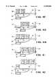
- FIGS. 4A through 4Jare schematic side elevational views sequentially illustrating the operation of a first embodiment of the transfer system illustrated in FIGS. 2 and 3.
- FIG. 6is an enlarged top plan view similar to FIG. 3 illustrating the use of the transfer system of this invention with a randomly oriented plurality of packages.
- FIG. 1a simplified schematic top plan view of an package handling system, indicated generally at 10, in accordance with this invention.
- the package handling system 10includes an upstream processing station 11, a conveyor system 12, and a downstream processing station 13.
- the upstream processing station 11,may for example, be a conventional filling station 11 which is adapted to receive packages, such as empty packages (not shown in FIG. 1), and fill them with a product.
- the filled packagesare fed from the filling station 11 through the conveyor system 12 to the downstream processing station 13.
- the downstream processing stationmay, for example, be a conventional packaging station 13, wherein the sealed packages from the conveyor system 12 are packaged into larger shipping packages.
- the conveyor system 12can include an upstream conveyor portion 14 that receives the filled packages from the filling station 11.
- the upstream conveyor portion 14transports the packages in a direction indicated by the upper arrow in FIG. 1 to an accumulator 15.
- the filled packagescan then pass from the accumulator 15 to a downstream conveyor portion conveyor 16 of the conveyor system 12.
- the downstream conveyor portion 16receives the packages from the accumulator 15 and transports them in a direction indicated by the lower arrow in FIG. 1 to the packaging station 13.
- a transfer systemfor transferring one or more packages 21 from the conveyor system 12 to the accumulator 15.
- the term "package”includes any product capable of being transported on a conveyor system including, but not limited to, boxes, containers, bottles, and outer-wrapped products, such as individually-wrapped cheese slices.
- the term "package”also includes a plurality of such individual products that are simultaneously moved, as described in detail below.
- the conveyor system 12includes a plurality of spaced-apart rollers 22 which are usually, but not necessarily, rotatably driven so as to move the packages 21 from the upstream station 11 to the downstream station 13.
- the accumulator 15includes a plurality of storage shelves, two of which are illustrated generally at 24 in FIG. 2. Each accumulator shelf 24 is formed by a plurality of spaced-apart fingers 26, which collectively define a surface upon which the packages 21 are to be temporarily stored when the accumulator 15 is operated.
- the accumulator shelves 24are connected to a lifting mechanism, indicated generally at 28.
- the lifting mechanism 28is provided to initially position an empty one of the shelves 24 directly adjacent the conveyor system 12. When that shelf 24 is filled with packages 21 in the manner discussed below, the lifting mechanism 28 is operated to move the filled shelf 24 vertically relative to the conveyor system 12 and position another empty shelf 24 directly adjacent thereto.
- This type of accumulator 15is often referred to as a vertical accumulator.
- each of the fingers 26 of the accumulator shelf 24is co-axially aligned with a corresponding one of the rollers 22 of the conveyor system 12.
- relatively narrow axial spaces 30 defined between adjacent ones of the fingers 26are co-axially aligned with relatively narrow axial spaces 32 defined between adjacent ones of the rollers 22.
- the transfer system 20 of this inventionincludes a plurality of relatively narrow fins 40 which are aligned with the aligned spaces 30 and 32.
- Each of the fins 40is preferably embodied as a relatively thin plate that can fit with clearance between adjacent ones of the fingers 26 and adjacent ones of the rollers 22.
- a preferred material for use in making the fins 40is any of the engineering plastics, including, but not limited to nylon, polyacetal, polycarbonate, and ABS resins. More preferably, the fins 40 are made from a LEXAN® or PLEXIGLAS® type material. As an example, for rollers having a center-to-center distance of about one inch, the fins 40 can be formed having a thickness in the range from about one-sixteenth inch to about one-quarter inch when made from a LEXAN® type material.
- the distance between the centers of adjacent ones of the rollers 22is about two inches or more. In order to transport small packages, packages, or flexible items, it is usually necessary to reduce this center-to-center roller distance. For some small packages or flexible items, a center-to-center distance of about one inch or less is desirable between adjacent ones of the rollers 22.
- a center-to-center distance of about one inch or lessis desirable between adjacent ones of the rollers 22.
- the fins 40are secured to a support structure, indicated generally at 42, for concurrent movement.
- the illustrated support structure 42is a generally U-shaped member including a pair of side rails 43 having a main rail 44 extending therebetween.
- the side rails 43extend generally parallel to the fins 40, while the main rail 44 extends generally perpendicularly thereto.
- the main rail 44 and the side rails 43may be formed from one or more tubular members, although such is not necessary.
- the main rail 44provides a support surface for securing a plurality of fins 40 thereto. As such, the main rail 44 provides rigidity to the elongate, relatively thin fins 40.
- the side rails 43are connected to the main rail 44 and extend beyond the conveyor 12.
- the side rails 43are more accessible to attach other components to the support structure 42.
- one or both of the side rails 43may be used as the structure used to move all of the fins 40 collectively as a group.
- the support structure 42may, however, be embodied as any convenient structure.
- the fins 40are secured to the support member 42 in any conventional manner such that movement of the support member 42 causes corresponding movement of the fins 40.
- the support structure 42may be configured to support a number of fins 40 which correspond generally to the number of spaces 30 and 32. Alternatively, the support structure 42 may be configured to support a greater number of fins 40 such that the transfer system 20 includes one or two portions which extend upstream and downstream (or both) from the accumulator 15. In a preferred embodiment of the invention, the overall length of the plurality or bank of fins 40 is approximately equal to the usable length of the shelf 24 of the accumulator 15.
- An actuator 46(see FIG. 2) is connected to the support structure 42 for moving the fins 40 as a group in one or more desired (horizontal and vertical, typically) directions.
- the movement of the fins 40will be described in detail below.
- the actuator 46should be capable of providing sufficient vertical motion of the fins 40 such that the fins 40 can be positioned both above and below the upper conveying surface defined by the rollers 22 of the conveyor system 12.
- the actuator 46may be embodied as any suitable structure capable of causing the desired movement of the fins 40 described below, including, but not limited to, fluid actuators (such as hydraulic or pneumatic actuators) and electromechanical actuators (such as linear actuators).
- FIGS. 4A through 4JThe operation of a first embodiment of the transfer system 20 is shown in FIGS. 4A through 4J.
- the illustrated fin 40(which preferably is representative of all of the fins 40) is a generally elongated, plate-shaped member having a relatively wide width relative to the rollers 22 of the conveyor system and the fingers 26 of the accumulator shelf 24.
- the upper surfaces of the fins 40are initially positioned below the conveying surface of the rollers 22 so that a first plurality of packages, such as illustrated at 21a, can be transported by the conveyor 12 into the accumulator 15.
- the fins 40remain the position illustrated in FIG. 4A and do not engage any of the packages 21a.
- the actuator 46 of the transfer system 20is operated to raise the main rail 44 of the support structure 42, thereby raising the fins 40 (as shown by the arrow in FIG. 4B) such that the upper surfaces thereof are elevated above the conveying surface of the rollers 22. In this manner, the packages 21a are elevated by two or more fins 40, depending on the size thereof.
- the actuator 46is operated to move the main rail 44 and the fins 40 laterally, as shown by the arrow in FIG. 4C, toward the fingers 26 of the accumulator 15. The actuator 46 is then operated to lower the main rail 44 and the fins 40 in the direction of the arrow in FIG.
- the actuator 46is operated to return the fins 40 laterally (in the direction of the arrow in FIG. 4E) to the initial position illustrated in FIG. 4A.
- the conveyor system 12can be operated to transport a second plurality of packages 21b into the accumulator 15, as shown in FIG. 4F.
- the actuator 46is again operated to elevate the fins 40 to lift the second plurality of packages 21b off of the rollers 22, as described above.
- the fins 40also lift the first plurality of packages 21a off of the fingers 26.
- both the first and second pluralities of packages 21a and 21bare supported on the fins 40.
- the actuator 46is then operated to move the fins 40 laterally as shown in FIG. 4G, then downwardly so as to deposit both the first and second pluralities of packages 21a and 21b on the fingers 26 of the accumulator 15.
- the first plurality of packages 21ais deposited at an intermediate position on the fingers 26, while the second plurality of packages 21b is deposited at the outermost position on the fingers 26.
- the fins 40are then lowered and returned to their initial position, as described above.
- the conveyor system 12can be operated to transport a third plurality of packages 21c into the accumulator 15, as shown in FIG. 4H.
- the actuator 46is again operated to elevate the fins 40 to lift the third plurality of packages 21c off of the rollers 22, as described above.
- the fins 40also lift the first and second pluralities of packages 21a and 21b off of the fingers 26.
- the first, second, and third pluralities of packages 21a, 21b, and 21care all supported on the fins 40.
- the actuator 46is then operated to move the fins 40 laterally as shown in FIG. 41, then downwardly so as to deposit both the first, second, and third pluralities of packages 21a, 21b, and 21c on the fingers 26 of the accumulator 15.
- the first plurality of packages 21ais deposited at an innermost position on the fingers 26
- the second plurality of packages 21bis deposited at the intermediate position on the fingers 26
- the third plurality of packages 21cis deposited at the outermost position on the fingers 26.
- the fins 40are then lowered and returned to their initial position, as described above. As shown in FIG.
- the accumulator shelf 24is elevated by the lift mechanism 28 to allow the next empty shelf 24 to be moved up and aligned with the conveyor rollers 22 for storage in the same manner.
- the reverse processis followed to unload the packages from the accumulator shelves 24 to the conveyor system 12.
- the actuator 46requires less programming and/or setup time to configure the transfer system 20 for operation.
- the transfer system 20 as a wholeoperates faster because the fins 40 need only move a predetermined amount in the horizontal direction to be clear of the conveyor 12, thus allowing additional packages 21 to move into this section of the conveyor 12.
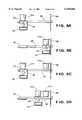
- FIGS. 5A through 5GThe operation of a second embodiment of the transfer system 20 is shown in FIGS. 5A through 5G.
- the illustrated fin 40'(which preferably is representative of all of the fins 40') is a generally elongated, plate-shaped member having a relatively narrow width relative to the rollers 22 of the conveyor system and the fingers 26 of the accumulator shelf 24.
- the upper surfaces of the fins 40'are initially positioned below the conveying surface of the rollers 22 so that a first plurality of packages, such as illustrated at 21a, can be transported by the conveyor 12 into the accumulator 15.
- the fins 40'remain the position illustrated in FIG. 4A and do not engage any of the packages 21a.
- the actuator 46 of the transfer system 20is operated to raise the main rail 44 of the support structure 42, thereby raising the fins 40' such that the upper surfaces thereof are elevated above the conveying surface of the rollers 22. In this manner, the packages 21a are elevated by two or more fins 40', depending on the size thereof.
- the actuator 46is operated to move the main rail 44 and the fins 40' laterally toward the fingers 26 of the accumulator 15, as shown in FIG. 5B.
- the actuator 46is then operated to lower the main rail 44 and the fins 40' so as to deposit the first plurality of packages 21a on the fingers 26 of the accumulator 15.
- the actuator 46is operated to return the fins 40' laterally to the initial position illustrated in FIG. 5A.
- the conveyor system 12can be operated to transport a second plurality of packages 21b into the accumulator 15, as shown in FIG. 5C.
- the actuator 46is again operated to elevate the fins 40' to lift the second plurality of packages 21b off of the rollers 22, as described above. It can be seen, however, that the fins 40' do not lift the first plurality of packages 21a off of the fingers 26 as described above.
- the actuator 46is then operated to move the fins 40' laterally as shown in FIG. 5D, then downwardly so as to deposit the second pluralities of packages 21b on the fingers 26 of the accumulator 15.
- the first plurality of packages 21aremains at the innermost position on the fingers 26, while the second plurality of packages 21b is deposited at the intermediate position on the fingers 26.
- the fins 40'are then lowered and returned to their initial position, as described above.
- the conveyor system 12can be operated to transport a third plurality of packages 21c into the accumulator 15, as shown in FIG. 5E.
- the actuator 46is again operated to elevate the fins 40' to lift the third plurality of packages 21c off of the rollers 22, as described above.
- the fins 40'do not lift the first and second pluralities of packages 21a and 21b off of the fingers 26, as described above.
- the actuator 46is then operated to move the fins 40' laterally as shown in FIG.
- the first plurality of packages 21aremains at the innermost position on the fingers 26
- the second plurality of packages 21bremains at the intermediate position on the fingers 26
- the third plurality of packages 21cis deposited at the outermost position on the fingers 26.
- the fins 40'are then lowered and returned to their initial position, as described above.
- the accumulator shelf 24is elevated by the lift mechanism 28 to allow the next empty shelf 24 to be moved up and aligned with the conveyor rollers 22 for storage in the same manner.
- the reverse processis followed to unload the packages from the accumulator shelves 24 to the conveyor system 12.
- FIG. 6An alternative mode of operation is illustrated in FIG. 6.
- the transfer system 20 of this inventioncan be used to transfer a random or mass accumulation of packages 21.
- a pair of side guide rails 80 and a stop gate 82are used to accumulate a plurality of packages 21 on a portion of the conveyor 12.
- the transfer system 20 of this inventionallows the use of relatively small center-to-center distances between the rollers 22 and the fins 40, it is possible to accumulate a mass of packages 21 which will be supported on at least two fins 40 when the transfer system 20 is operated.
- Some packages 21 or other types of packagesmay be supported in a stable manner by two points, while other packages 21 require the use of three points.
- the transfer system 20 of this inventioncan also be used when the conveyor 12 is embodied as a flat belt (not shown) or other continuous surface transportation mechanism, rather than the illustrated rollers 22.
- a conventional "pick and place” device(not shown) can be used to pick up the packages 21 from the flat belt conveyor, move them laterally a predetermined distance, and place them down on the transfer fins 40.
- the upper surface of the transfer fins 40may be vertically aligned with the conveying surface of the conveyor 12, although such is not necessary.
- This embodimentalso allows a vertical accumulator 15 to be used with the belt-type conveyors without modifications that reduce its storage capacity. More specifically, if the packages 21 were moved directly from the conveyor 12 to the accumulator 15 with a pick and place device, additional vertical space would have to be provided between the accumulator shelves to accommodate the pick and place device. Using the transfer system 20 of this invention, the vertical clearances required by the pick and place device are met by first positioning the packages 21 on the transfer fins 40 which have complete free space above their upper surfaces 40c.
Landscapes
- Engineering & Computer Science (AREA)
- Mechanical Engineering (AREA)
- Warehouses Or Storage Devices (AREA)
- Attitude Control For Articles On Conveyors (AREA)
Abstract
Description
Claims (9)
Priority Applications (1)
| Application Number | Priority Date | Filing Date | Title |
|---|---|---|---|
| US08/969,052US6158566A (en) | 1997-11-12 | 1997-11-12 | Transfer system for a conveyor |
Applications Claiming Priority (1)
| Application Number | Priority Date | Filing Date | Title |
|---|---|---|---|
| US08/969,052US6158566A (en) | 1997-11-12 | 1997-11-12 | Transfer system for a conveyor |
Publications (1)
| Publication Number | Publication Date |
|---|---|
| US6158566Atrue US6158566A (en) | 2000-12-12 |
Family
ID=25515111
Family Applications (1)
| Application Number | Title | Priority Date | Filing Date |
|---|---|---|---|
| US08/969,052Expired - LifetimeUS6158566A (en) | 1997-11-12 | 1997-11-12 | Transfer system for a conveyor |
Country Status (1)
| Country | Link |
|---|---|
| US (1) | US6158566A (en) |
Cited By (23)
| Publication number | Priority date | Publication date | Assignee | Title |
|---|---|---|---|---|
| US6371277B1 (en)* | 1998-02-09 | 2002-04-16 | Elpatronic Ag | Conveyor device |
| US6464064B1 (en)* | 1999-08-06 | 2002-10-15 | Wolfgang Rieg | Device for transporting goods from one conveyor device to at least one other conveyor device |
| US20050074315A1 (en)* | 2001-06-27 | 2005-04-07 | Karl Freudelsperger | Storage and retrieval unit and method for controlling product storage shelving, especially a commission device |
| US20070134077A1 (en)* | 2005-12-08 | 2007-06-14 | Conestoga Cold Storage | Rack, conveyor and shuttle automated pick system |
| US20080188977A1 (en)* | 2004-10-18 | 2008-08-07 | Foodcap International Lmited | Processing, Storage And Distribution System For Perishable Food Products |
| WO2007089269A3 (en)* | 2005-06-27 | 2009-04-30 | Matrix Scient Llc | Non-palletized cage handling system and method |
| US20100290872A1 (en)* | 2009-05-18 | 2010-11-18 | Crossing Automation, Inc. | Substrate container storage system |
| US20100290873A1 (en)* | 2009-05-18 | 2010-11-18 | Crossing Automation, Inc. | Integrated systems for interfacing with substrate container storage systems |
| US20100316470A1 (en)* | 2009-04-10 | 2010-12-16 | Casepick Systems, Llc | Control system for storage and retrieval systems |
| AU2006322594B2 (en)* | 2005-12-08 | 2011-12-22 | Conestoga Cold Storage | Rack, conveyor and shuttle automated pick system |
| US20140311858A1 (en)* | 2013-03-13 | 2014-10-23 | Symbotic, LLC | Automated storage and retrieval system structure |
| US8919801B2 (en) | 2010-12-15 | 2014-12-30 | Symbotic, LLC | Suspension system for autonomous transports |
| US8965619B2 (en) | 2010-12-15 | 2015-02-24 | Symbotic, LLC | Bot having high speed stability |
| US9187244B2 (en) | 2010-12-15 | 2015-11-17 | Symbotic, LLC | BOT payload alignment and sensing |
| WO2016012923A1 (en) | 2014-07-23 | 2016-01-28 | Corob S.P.A. Con Socio Unico | Apparatus for moving receptacles |
| US9321591B2 (en) | 2009-04-10 | 2016-04-26 | Symbotic, LLC | Autonomous transports for storage and retrieval systems |
| US9499338B2 (en) | 2010-12-15 | 2016-11-22 | Symbotic, LLC | Automated bot transfer arm drive system |
| US9561905B2 (en) | 2010-12-15 | 2017-02-07 | Symbotic, LLC | Autonomous transport vehicle |
| US9938079B1 (en) | 2016-08-12 | 2018-04-10 | North Central Door Company, LLC | Automated accumulator |
| CN110304388A (en)* | 2019-07-10 | 2019-10-08 | 四川易景智能终端有限公司 | Unmanned warehouse intelligent dispatching system |
| US10822168B2 (en) | 2010-12-15 | 2020-11-03 | Symbotic Llc | Warehousing scalable storage structure |
| US10894663B2 (en) | 2013-09-13 | 2021-01-19 | Symbotic Llc | Automated storage and retrieval system |
| US11078017B2 (en) | 2010-12-15 | 2021-08-03 | Symbotic Llc | Automated bot with transfer arm |
Citations (18)
| Publication number | Priority date | Publication date | Assignee | Title |
|---|---|---|---|---|
| US1695115A (en)* | 1927-06-02 | 1928-12-11 | Coe Mfg Co | Conveyer |
| US3991685A (en)* | 1975-02-25 | 1976-11-16 | Toby Enterprises | Transferring and accumulating device for sliced comestible products |
| US4010843A (en)* | 1974-06-20 | 1977-03-08 | Raymond Roger Louis Lucas | Device for transferring a load from one conveyor to a second conveyor |
| US4042118A (en)* | 1976-03-09 | 1977-08-16 | Schmidt Hans V | Combination roller conveyor and cross-conveyor system |
| US4048784A (en)* | 1975-02-25 | 1977-09-20 | Max Edward Toby | Loader for sliced comestible product |
| US4273243A (en)* | 1979-04-18 | 1981-06-16 | Locher Frank S | Lift centering device |
| US4273234A (en)* | 1979-02-02 | 1981-06-16 | Bourgeois Ronald D | Conveyor storage system |
| US4499987A (en)* | 1982-08-30 | 1985-02-19 | Long Charles P | Accumulator for a carton filling and packing production line |
| US4505375A (en)* | 1981-07-20 | 1985-03-19 | Ciba-Geigy Corporation | Apparatus for conveying flat goods one side of which bears a liquid layer |
| US4609091A (en)* | 1982-08-09 | 1986-09-02 | Dorner Mfg. Corp. | Storage unit for a conveyor system |
| US4715766A (en)* | 1982-12-20 | 1987-12-29 | Gebhardt Fordertechnik Gmbh | Combined distribution apparatus for piece goods |
| US4865180A (en)* | 1985-08-07 | 1989-09-12 | Lamb Technicon Corp. | Workpiece transfer system |
| US4953687A (en)* | 1987-09-22 | 1990-09-04 | Solis S.R.L. | Method and apparatus for automatically transferring and accumulating groups of flaccid articles |
| US5012918A (en)* | 1988-12-30 | 1991-05-07 | Therma-Tron-X, Inc. | Intermittent work conveying apparatus |
| US5074096A (en)* | 1989-06-24 | 1991-12-24 | Focke & Co., (Gmbh & Co.) | Production plant for producing large units in the form of boarded bundles of groups of small packs of paper tissues including a reservoir unit for temporarily storing the small packs during a malfunction of the plant |
| US5092452A (en)* | 1990-12-06 | 1992-03-03 | Kabushiki Kaisha Murao And Company | Cheese stocker |
| US5238100A (en)* | 1991-06-13 | 1993-08-24 | Ford Motor Company | Method and apparatus for handling glass sheets |
| US5255773A (en)* | 1993-01-21 | 1993-10-26 | Roe Incorporated | Accumulator for conveyor system |
- 1997
- 1997-11-12USUS08/969,052patent/US6158566A/ennot_activeExpired - Lifetime
Patent Citations (19)
| Publication number | Priority date | Publication date | Assignee | Title |
|---|---|---|---|---|
| US1695115A (en)* | 1927-06-02 | 1928-12-11 | Coe Mfg Co | Conveyer |
| US4010843A (en)* | 1974-06-20 | 1977-03-08 | Raymond Roger Louis Lucas | Device for transferring a load from one conveyor to a second conveyor |
| US3991685A (en)* | 1975-02-25 | 1976-11-16 | Toby Enterprises | Transferring and accumulating device for sliced comestible products |
| US4048784A (en)* | 1975-02-25 | 1977-09-20 | Max Edward Toby | Loader for sliced comestible product |
| US4042118A (en)* | 1976-03-09 | 1977-08-16 | Schmidt Hans V | Combination roller conveyor and cross-conveyor system |
| US4273234A (en)* | 1979-02-02 | 1981-06-16 | Bourgeois Ronald D | Conveyor storage system |
| US4273243A (en)* | 1979-04-18 | 1981-06-16 | Locher Frank S | Lift centering device |
| US4505375A (en)* | 1981-07-20 | 1985-03-19 | Ciba-Geigy Corporation | Apparatus for conveying flat goods one side of which bears a liquid layer |
| US4609091A (en)* | 1982-08-09 | 1986-09-02 | Dorner Mfg. Corp. | Storage unit for a conveyor system |
| US4499987A (en)* | 1982-08-30 | 1985-02-19 | Long Charles P | Accumulator for a carton filling and packing production line |
| US4715766A (en)* | 1982-12-20 | 1987-12-29 | Gebhardt Fordertechnik Gmbh | Combined distribution apparatus for piece goods |
| US4865180A (en)* | 1985-08-07 | 1989-09-12 | Lamb Technicon Corp. | Workpiece transfer system |
| US4953687A (en)* | 1987-09-22 | 1990-09-04 | Solis S.R.L. | Method and apparatus for automatically transferring and accumulating groups of flaccid articles |
| US5012918A (en)* | 1988-12-30 | 1991-05-07 | Therma-Tron-X, Inc. | Intermittent work conveying apparatus |
| US5074096A (en)* | 1989-06-24 | 1991-12-24 | Focke & Co., (Gmbh & Co.) | Production plant for producing large units in the form of boarded bundles of groups of small packs of paper tissues including a reservoir unit for temporarily storing the small packs during a malfunction of the plant |
| US5092452A (en)* | 1990-12-06 | 1992-03-03 | Kabushiki Kaisha Murao And Company | Cheese stocker |
| US5238100A (en)* | 1991-06-13 | 1993-08-24 | Ford Motor Company | Method and apparatus for handling glass sheets |
| US5255773A (en)* | 1993-01-21 | 1993-10-26 | Roe Incorporated | Accumulator for conveyor system |
| US5366063A (en)* | 1993-01-21 | 1994-11-22 | Roe Incorporated | Accumulator for conveyor system |
Cited By (78)
| Publication number | Priority date | Publication date | Assignee | Title |
|---|---|---|---|---|
| US6371277B1 (en)* | 1998-02-09 | 2002-04-16 | Elpatronic Ag | Conveyor device |
| US6464064B1 (en)* | 1999-08-06 | 2002-10-15 | Wolfgang Rieg | Device for transporting goods from one conveyor device to at least one other conveyor device |
| US20050074315A1 (en)* | 2001-06-27 | 2005-04-07 | Karl Freudelsperger | Storage and retrieval unit and method for controlling product storage shelving, especially a commission device |
| US7344348B2 (en)* | 2001-06-27 | 2008-03-18 | Knapp Logistik Automation Gmbh | Storage and retrieval unit and method for controlling product storage shelving, especially a commission device |
| US20080188977A1 (en)* | 2004-10-18 | 2008-08-07 | Foodcap International Lmited | Processing, Storage And Distribution System For Perishable Food Products |
| WO2007089269A3 (en)* | 2005-06-27 | 2009-04-30 | Matrix Scient Llc | Non-palletized cage handling system and method |
| AU2006322594B2 (en)* | 2005-12-08 | 2011-12-22 | Conestoga Cold Storage | Rack, conveyor and shuttle automated pick system |
| US20070134077A1 (en)* | 2005-12-08 | 2007-06-14 | Conestoga Cold Storage | Rack, conveyor and shuttle automated pick system |
| US7686560B2 (en)* | 2005-12-08 | 2010-03-30 | Conestoga Cold Storage | Rack, conveyor and shuttle automated pick system |
| US8740538B2 (en) | 2009-04-10 | 2014-06-03 | Symbotic, LLC | Storage and retrieval system |
| US9051120B2 (en) | 2009-04-10 | 2015-06-09 | Symbotic Llc | Control system for storage and retrieval systems |
| US20100316468A1 (en)* | 2009-04-10 | 2010-12-16 | Casepick Systems, Llc | Storage and retrieval system |
| US20100316469A1 (en)* | 2009-04-10 | 2010-12-16 | Casepick Systems, Llc | Autonomous transports for storage and retrieval systems |
| US20100322747A1 (en)* | 2009-04-10 | 2010-12-23 | Casepick Systems, Llc | Storage and retrieval system |
| US20100322746A1 (en)* | 2009-04-10 | 2010-12-23 | Casepick Systems, Llc | Lift interface for storage and retrieval systems |
| US12084279B2 (en) | 2009-04-10 | 2024-09-10 | Symbotic Llc | Control system for storage and retrieval systems |
| US8425173B2 (en)* | 2009-04-10 | 2013-04-23 | Symbotic Llc | Autonomous transports for storage and retrieval systems |
| US8594835B2 (en) | 2009-04-10 | 2013-11-26 | Symbotic, LLC | Control system for storage and retrieval systems |
| US9694975B2 (en) | 2009-04-10 | 2017-07-04 | Symbotic, LLC | Lift interface for storage and retrieval systems |
| US12358723B2 (en) | 2009-04-10 | 2025-07-15 | Symbotic Llc | Storage and retrieval system |
| US11939158B2 (en) | 2009-04-10 | 2024-03-26 | Symbotic Llc | Storage and retrieval system |
| US11858740B2 (en) | 2009-04-10 | 2024-01-02 | Symbotic Llc | Storage and retrieval system |
| US11661279B2 (en) | 2009-04-10 | 2023-05-30 | Symbotic Llc | Autonomous transports for storage and retrieval systems |
| US11608228B2 (en) | 2009-04-10 | 2023-03-21 | Symbotic Llc | Control system for storage and retrieval systems |
| US20100316470A1 (en)* | 2009-04-10 | 2010-12-16 | Casepick Systems, Llc | Control system for storage and retrieval systems |
| US9096375B2 (en) | 2009-04-10 | 2015-08-04 | Symbotic, LLC | Storage and retrieval system |
| EP2436619A3 (en)* | 2009-04-10 | 2015-08-26 | Casepick Systems, LLC | Vertical conveyor system |
| US11254501B2 (en) | 2009-04-10 | 2022-02-22 | Symbotic Llc | Storage and retrieval system |
| US11124361B2 (en) | 2009-04-10 | 2021-09-21 | Symbotic Llc | Storage and retrieval system |
| US10759600B2 (en) | 2009-04-10 | 2020-09-01 | Symbotic Llc | Autonomous transports for storage and retrieval systems |
| US9321591B2 (en) | 2009-04-10 | 2016-04-26 | Symbotic, LLC | Autonomous transports for storage and retrieval systems |
| US10717599B2 (en) | 2009-04-10 | 2020-07-21 | Symbotic, LLC | Control system for storage and retrieval systems |
| US10556743B2 (en) | 2009-04-10 | 2020-02-11 | Symbotic, LLC | Storage and retrieval system |
| US10442622B2 (en) | 2009-04-10 | 2019-10-15 | Symbotic, LLC | Control system for storage and retrieval systems |
| US10239691B2 (en) | 2009-04-10 | 2019-03-26 | Symbotic, LLC | Storage and retrieval system |
| US10207870B2 (en) | 2009-04-10 | 2019-02-19 | Symbotic, LLC | Autonomous transports for storage and retrieval systems |
| US10035649B2 (en) | 2009-04-10 | 2018-07-31 | Symbotic Llc | Control system for storage and retrieval systems |
| US9771217B2 (en) | 2009-04-10 | 2017-09-26 | Symbotic, LLC | Control system for storage and retrieval systems |
| US9725239B2 (en) | 2009-04-10 | 2017-08-08 | Symbotic, LLC | Storage and retrieval system |
| US8851820B2 (en)* | 2009-05-18 | 2014-10-07 | Brooks Automation, Inc. | Substrate container storage system |
| US8882433B2 (en) | 2009-05-18 | 2014-11-11 | Brooks Automation, Inc. | Integrated systems for interfacing with substrate container storage systems |
| US20100290872A1 (en)* | 2009-05-18 | 2010-11-18 | Crossing Automation, Inc. | Substrate container storage system |
| US20100290873A1 (en)* | 2009-05-18 | 2010-11-18 | Crossing Automation, Inc. | Integrated systems for interfacing with substrate container storage systems |
| US11273981B2 (en) | 2010-12-15 | 2022-03-15 | Symbolic Llc | Automated bot transfer arm drive system |
| US9423796B2 (en) | 2010-12-15 | 2016-08-23 | Symbotic Llc | Bot having high speed stability |
| US9908698B2 (en) | 2010-12-15 | 2018-03-06 | Symbotic, LLC | Automated bot transfer arm drive system |
| US12214959B2 (en) | 2010-12-15 | 2025-02-04 | Symbotic Llc | Automated bot with transfer arm |
| US9946265B2 (en) | 2010-12-15 | 2018-04-17 | Symbotic, LLC | Bot having high speed stability |
| US9561905B2 (en) | 2010-12-15 | 2017-02-07 | Symbotic, LLC | Autonomous transport vehicle |
| US8919801B2 (en) | 2010-12-15 | 2014-12-30 | Symbotic, LLC | Suspension system for autonomous transports |
| US9550225B2 (en) | 2010-12-15 | 2017-01-24 | Symbotic Llc | Bot having high speed stability |
| US9499338B2 (en) | 2010-12-15 | 2016-11-22 | Symbotic, LLC | Automated bot transfer arm drive system |
| US10280000B2 (en) | 2010-12-15 | 2019-05-07 | Symbotic, LLC | Suspension system for autonomous transports |
| US11952214B2 (en) | 2010-12-15 | 2024-04-09 | Symbotic Llc | Automated bot transfer arm drive system |
| US10414586B2 (en) | 2010-12-15 | 2019-09-17 | Symbotic, LLC | Autonomous transport vehicle |
| US9676551B2 (en) | 2010-12-15 | 2017-06-13 | Symbotic, LLC | Bot payload alignment and sensing |
| US8965619B2 (en) | 2010-12-15 | 2015-02-24 | Symbotic, LLC | Bot having high speed stability |
| US9156394B2 (en) | 2010-12-15 | 2015-10-13 | Symbotic, LLC | Suspension system for autonomous transports |
| US10683169B2 (en) | 2010-12-15 | 2020-06-16 | Symbotic, LLC | Automated bot transfer arm drive system |
| US9862543B2 (en) | 2010-12-15 | 2018-01-09 | Symbiotic, LLC | Bot payload alignment and sensing |
| US9327903B2 (en) | 2010-12-15 | 2016-05-03 | Symbotic, LLC | Suspension system for autonomous transports |
| US10822168B2 (en) | 2010-12-15 | 2020-11-03 | Symbotic Llc | Warehousing scalable storage structure |
| US9187244B2 (en) | 2010-12-15 | 2015-11-17 | Symbotic, LLC | BOT payload alignment and sensing |
| US11078017B2 (en) | 2010-12-15 | 2021-08-03 | Symbotic Llc | Automated bot with transfer arm |
| US9409709B2 (en)* | 2013-03-13 | 2016-08-09 | Symbotic, LLC | Automated storage and retrieval system structure |
| US20140311858A1 (en)* | 2013-03-13 | 2014-10-23 | Symbotic, LLC | Automated storage and retrieval system structure |
| US10196207B2 (en) | 2013-03-13 | 2019-02-05 | Symbotic, LLC | Automated storage and retrieval system structure |
| US11708218B2 (en) | 2013-09-13 | 2023-07-25 | Symbolic Llc | Automated storage and retrieval system |
| US10894663B2 (en) | 2013-09-13 | 2021-01-19 | Symbotic Llc | Automated storage and retrieval system |
| WO2016012923A1 (en) | 2014-07-23 | 2016-01-28 | Corob S.P.A. Con Socio Unico | Apparatus for moving receptacles |
| KR102460569B1 (en) | 2014-07-23 | 2022-10-27 | 크롭 에스.피.에이. 콘 소시오 유니코 | Apparatus for moving receptacles |
| JP2017530072A (en)* | 2014-07-23 | 2017-10-12 | コロボ ソシエタ ペル アチオニ コン ソシオ ウニコCorob S.P.A.Con Socio Unico | Equipment for moving containers |
| CN106714953B (en)* | 2014-07-23 | 2019-08-30 | 克洛布单一股东股份公司 | For moving the device of container |
| KR20170036025A (en)* | 2014-07-23 | 2017-03-31 | 크롭 에스.피.에이. 콘 소시오 유니코 | Apparatus for moving receptacles |
| CN106714953A (en)* | 2014-07-23 | 2017-05-24 | 克洛布单股东股份公司 | Apparatus for moving receptacles |
| US9938079B1 (en) | 2016-08-12 | 2018-04-10 | North Central Door Company, LLC | Automated accumulator |
| CN110304388B (en)* | 2019-07-10 | 2021-03-02 | 四川易景智能终端有限公司 | Intelligent scheduling system for unmanned warehouse |
| CN110304388A (en)* | 2019-07-10 | 2019-10-08 | 四川易景智能终端有限公司 | Unmanned warehouse intelligent dispatching system |
Similar Documents
| Publication | Publication Date | Title |
|---|---|---|
| US6158566A (en) | Transfer system for a conveyor | |
| US8397897B2 (en) | Vertical spiral multilevel sorter and merge conveyor for three dimensional automated pick module | |
| US11945653B2 (en) | Sequence systems and methods | |
| US11286118B2 (en) | Pickface builder for storage and retrieval systems | |
| JP6679678B2 (en) | Method for providing a transportation unit from a storage facility | |
| US9371183B2 (en) | Multilevel vertical conveyor platform guides | |
| US8671649B2 (en) | Separate packing station | |
| US5366063A (en) | Accumulator for conveyor system | |
| EP2393736B1 (en) | Method and device for collecting different products forming part of an order | |
| US6499582B1 (en) | Chute | |
| WO2009089159A2 (en) | Vertical spiral multilevel sorter and merge conveyor for three dimensional automated pick module | |
| US20140014467A1 (en) | Automated case order sequencing method and system | |
| KR20220048940A (en) | Article transport facility | |
| US5215421A (en) | Warehouse system | |
| US4950119A (en) | Storage and retrieval system | |
| US5577595A (en) | Accumulator for conveyor system | |
| JPH01162632A (en) | Device and method of superposing article | |
| US20060072990A1 (en) | Device for distributing unit load freight carriers | |
| JP3800961B2 (en) | Automated warehouse and automated warehouse operation method | |
| KR100222395B1 (en) | Picking apparatus | |
| JP2001072207A (en) | Article storage / sorting apparatus and article storage / sorting method using the same | |
| JPS63117806A (en) | Transferring device for three-dimensional automatic warehouse | |
| JPH09202409A (en) | Container storage automated warehouse | |
| JPH042484B2 (en) | ||
| JPH0281829A (en) | Device for conveying product |
Legal Events
| Date | Code | Title | Description |
|---|---|---|---|
| AS | Assignment | Owner name:ROE INCORPORATED, OHIO Free format text:ASSIGNMENT OF ASSIGNORS INTEREST;ASSIGNOR:POLLOCK, DANIEL A.;REEL/FRAME:008893/0284 Effective date:19980105 | |
| AS | Assignment | Owner name:DILLIN ENGINEERED SYSTEMS CORPORATION, OHIO Free format text:ASSIGNMENT OF ASSIGNORS INTEREST;ASSIGNOR:ROE INCORPORATED;REEL/FRAME:010618/0296 Effective date:20000211 | |
| AS | Assignment | Owner name:HUNTINGTON NATIONAL BANK, THE, OHIO Free format text:SECURITY AGREEMENT;ASSIGNOR:DILLIN ENGINEERED SYSTEMS CORP.;REEL/FRAME:010731/0183 Effective date:20000128 | |
| STCF | Information on status: patent grant | Free format text:PATENTED CASE | |
| FEPP | Fee payment procedure | Free format text:PAYER NUMBER DE-ASSIGNED (ORIGINAL EVENT CODE: RMPN); ENTITY STATUS OF PATENT OWNER: SMALL ENTITY Free format text:PAYOR NUMBER ASSIGNED (ORIGINAL EVENT CODE: ASPN); ENTITY STATUS OF PATENT OWNER: SMALL ENTITY | |
| FPAY | Fee payment | Year of fee payment:4 | |
| FPAY | Fee payment | Year of fee payment:8 | |
| FPAY | Fee payment | Year of fee payment:12 |