US6158458A - Medical intravenous administration line connectors having a luer or pressure activated valve - Google Patents
Medical intravenous administration line connectors having a luer or pressure activated valveDownload PDFInfo
- Publication number
- US6158458A US6158458AUS09/344,403US34440399AUS6158458AUS 6158458 AUS6158458 AUS 6158458AUS 34440399 AUS34440399 AUS 34440399AUS 6158458 AUS6158458 AUS 6158458A
- Authority
- US
- United States
- Prior art keywords
- valve
- fluid
- sealing surface
- coupling member
- luer
- Prior art date
- Legal status (The legal status is an assumption and is not a legal conclusion. Google has not performed a legal analysis and makes no representation as to the accuracy of the status listed.)
- Expired - Lifetime
Links
- 238000001990intravenous administrationMethods0.000titleabstractdescription36
- 239000012530fluidSubstances0.000claimsabstractdescription89
- 230000008878couplingEffects0.000claimsabstractdescription75
- 238000010168coupling processMethods0.000claimsabstractdescription75
- 238000005859coupling reactionMethods0.000claimsabstractdescription75
- 238000007789sealingMethods0.000claimsabstractdescription63
- 238000004891communicationMethods0.000claimsabstractdescription8
- 230000000903blocking effectEffects0.000claimsabstractdescription5
- 230000013011matingEffects0.000claimsdescription20
- 239000004417polycarbonateSubstances0.000claimsdescription2
- 229920000515polycarbonatePolymers0.000claimsdescription2
- 229920001296polysiloxanePolymers0.000claimsdescription2
- 230000037361pathwayEffects0.000claims2
- 239000008280bloodSubstances0.000abstractdescription8
- 210000004369bloodAnatomy0.000abstractdescription8
- 230000037452primingEffects0.000abstractdescription5
- 230000007246mechanismEffects0.000abstractdescription2
- 238000002347injectionMethods0.000description37
- 239000007924injectionSubstances0.000description37
- HTTJABKRGRZYRN-UHFFFAOYSA-NHeparinChemical compoundOC1C(NC(=O)C)C(O)OC(COS(O)(=O)=O)C1OC1C(OS(O)(=O)=O)C(O)C(OC2C(C(OS(O)(=O)=O)C(OC3C(C(O)C(O)C(O3)C(O)=O)OS(O)(=O)=O)C(CO)O2)NS(O)(=O)=O)C(C(O)=O)O1HTTJABKRGRZYRN-UHFFFAOYSA-N0.000description8
- 229960002897heparinDrugs0.000description8
- 229920000669heparinPolymers0.000description8
- 230000000153supplemental effectEffects0.000description8
- 238000002642intravenous therapyMethods0.000description7
- 239000004033plasticSubstances0.000description6
- 230000008901benefitEffects0.000description5
- 206010069803Injury associated with deviceDiseases0.000description4
- 239000007788liquidSubstances0.000description4
- 244000052769pathogenSpecies0.000description4
- 230000004913activationEffects0.000description3
- 238000001994activationMethods0.000description3
- 239000010836blood and blood productSubstances0.000description3
- 238000013461designMethods0.000description3
- 239000003814drugSubstances0.000description3
- 238000011010flushing procedureMethods0.000description3
- 208000014674injuryDiseases0.000description3
- 238000004519manufacturing processMethods0.000description3
- 239000000243solutionSubstances0.000description3
- 238000002560therapeutic procedureMethods0.000description3
- 208000012266Needlestick injuryDiseases0.000description2
- 208000027418Wounds and injuryDiseases0.000description2
- 229940125691blood productDrugs0.000description2
- 230000006378damageEffects0.000description2
- 230000004927fusionEffects0.000description2
- 229920000126latexPolymers0.000description2
- 239000000463materialSubstances0.000description2
- 238000000034methodMethods0.000description2
- 239000003182parenteral nutrition solutionSubstances0.000description2
- 230000000087stabilizing effectEffects0.000description2
- 238000010561standard procedureMethods0.000description2
- 210000003462veinAnatomy0.000description2
- 208000030507AIDSDiseases0.000description1
- 206010011409Cross infectionDiseases0.000description1
- 241000725303Human immunodeficiency virusSpecies0.000description1
- 206010029803Nosocomial infectionDiseases0.000description1
- 229920004482WACKER®Polymers0.000description1
- 230000009471actionEffects0.000description1
- 239000002390adhesive tapeSubstances0.000description1
- 230000000712assemblyEffects0.000description1
- 238000000429assemblyMethods0.000description1
- 230000009286beneficial effectEffects0.000description1
- 239000013060biological fluidSubstances0.000description1
- 238000009534blood testMethods0.000description1
- 230000008859changeEffects0.000description1
- 238000011109contaminationMethods0.000description1
- 201000010099diseaseDiseases0.000description1
- 208000037265diseases, disorders, signs and symptomsDiseases0.000description1
- 229940079593drugDrugs0.000description1
- 239000000975dyeSubstances0.000description1
- 230000000694effectsEffects0.000description1
- 229920001971elastomerPolymers0.000description1
- 230000002996emotional effectEffects0.000description1
- 230000002708enhancing effectEffects0.000description1
- 230000005484gravityEffects0.000description1
- 238000001802infusionMethods0.000description1
- 238000001746injection mouldingMethods0.000description1
- 239000004816latexSubstances0.000description1
- 239000006193liquid solutionSubstances0.000description1
- 238000010999medical injectionMethods0.000description1
- 238000012986modificationMethods0.000description1
- 230000004048modificationEffects0.000description1
- 239000003186pharmaceutical solutionSubstances0.000description1
- 239000007787solidSubstances0.000description1
- 230000008733traumaEffects0.000description1
Images


Classifications
- A—HUMAN NECESSITIES
- A61—MEDICAL OR VETERINARY SCIENCE; HYGIENE
- A61J—CONTAINERS SPECIALLY ADAPTED FOR MEDICAL OR PHARMACEUTICAL PURPOSES; DEVICES OR METHODS SPECIALLY ADAPTED FOR BRINGING PHARMACEUTICAL PRODUCTS INTO PARTICULAR PHYSICAL OR ADMINISTERING FORMS; DEVICES FOR ADMINISTERING FOOD OR MEDICINES ORALLY; BABY COMFORTERS; DEVICES FOR RECEIVING SPITTLE
- A61J1/00—Containers specially adapted for medical or pharmaceutical purposes
- A61J1/14—Details; Accessories therefor
- A61J1/20—Arrangements for transferring or mixing fluids, e.g. from vial to syringe
- A61J1/2096—Combination of a vial and a syringe for transferring or mixing their contents
- A—HUMAN NECESSITIES
- A61—MEDICAL OR VETERINARY SCIENCE; HYGIENE
- A61M—DEVICES FOR INTRODUCING MEDIA INTO, OR ONTO, THE BODY; DEVICES FOR TRANSDUCING BODY MEDIA OR FOR TAKING MEDIA FROM THE BODY; DEVICES FOR PRODUCING OR ENDING SLEEP OR STUPOR
- A61M39/00—Tubes, tube connectors, tube couplings, valves, access sites or the like, specially adapted for medical use
- A61M39/22—Valves or arrangement of valves
- A61M39/24—Check- or non-return valves
- A—HUMAN NECESSITIES
- A61—MEDICAL OR VETERINARY SCIENCE; HYGIENE
- A61M—DEVICES FOR INTRODUCING MEDIA INTO, OR ONTO, THE BODY; DEVICES FOR TRANSDUCING BODY MEDIA OR FOR TAKING MEDIA FROM THE BODY; DEVICES FOR PRODUCING OR ENDING SLEEP OR STUPOR
- A61M39/00—Tubes, tube connectors, tube couplings, valves, access sites or the like, specially adapted for medical use
- A61M39/22—Valves or arrangement of valves
- A61M39/26—Valves closing automatically on disconnecting the line and opening on reconnection thereof
- F—MECHANICAL ENGINEERING; LIGHTING; HEATING; WEAPONS; BLASTING
- F16—ENGINEERING ELEMENTS AND UNITS; GENERAL MEASURES FOR PRODUCING AND MAINTAINING EFFECTIVE FUNCTIONING OF MACHINES OR INSTALLATIONS; THERMAL INSULATION IN GENERAL
- F16L—PIPES; JOINTS OR FITTINGS FOR PIPES; SUPPORTS FOR PIPES, CABLES OR PROTECTIVE TUBING; MEANS FOR THERMAL INSULATION IN GENERAL
- F16L41/00—Branching pipes; Joining pipes to walls
- F16L41/02—Branch units, e.g. made in one piece, welded, riveted
- F16L41/03—Branch units, e.g. made in one piece, welded, riveted comprising junction pieces for four or more pipe members
- F—MECHANICAL ENGINEERING; LIGHTING; HEATING; WEAPONS; BLASTING
- F16—ENGINEERING ELEMENTS AND UNITS; GENERAL MEASURES FOR PRODUCING AND MAINTAINING EFFECTIVE FUNCTIONING OF MACHINES OR INSTALLATIONS; THERMAL INSULATION IN GENERAL
- F16L—PIPES; JOINTS OR FITTINGS FOR PIPES; SUPPORTS FOR PIPES, CABLES OR PROTECTIVE TUBING; MEANS FOR THERMAL INSULATION IN GENERAL
- F16L41/00—Branching pipes; Joining pipes to walls
- F16L41/08—Joining pipes to walls or pipes, the joined pipe axis being perpendicular to the plane of a wall or to the axis of another pipe
- F16L41/16—Joining pipes to walls or pipes, the joined pipe axis being perpendicular to the plane of a wall or to the axis of another pipe the branch pipe comprising fluid cut-off means
- A—HUMAN NECESSITIES
- A61—MEDICAL OR VETERINARY SCIENCE; HYGIENE
- A61J—CONTAINERS SPECIALLY ADAPTED FOR MEDICAL OR PHARMACEUTICAL PURPOSES; DEVICES OR METHODS SPECIALLY ADAPTED FOR BRINGING PHARMACEUTICAL PRODUCTS INTO PARTICULAR PHYSICAL OR ADMINISTERING FORMS; DEVICES FOR ADMINISTERING FOOD OR MEDICINES ORALLY; BABY COMFORTERS; DEVICES FOR RECEIVING SPITTLE
- A61J1/00—Containers specially adapted for medical or pharmaceutical purposes
- A61J1/14—Details; Accessories therefor
- A61J1/20—Arrangements for transferring or mixing fluids, e.g. from vial to syringe
- A61J1/2003—Accessories used in combination with means for transfer or mixing of fluids, e.g. for activating fluid flow, separating fluids, filtering fluid or venting
- A61J1/2006—Piercing means
- A61J1/201—Piercing means having one piercing end
- A—HUMAN NECESSITIES
- A61—MEDICAL OR VETERINARY SCIENCE; HYGIENE
- A61J—CONTAINERS SPECIALLY ADAPTED FOR MEDICAL OR PHARMACEUTICAL PURPOSES; DEVICES OR METHODS SPECIALLY ADAPTED FOR BRINGING PHARMACEUTICAL PRODUCTS INTO PARTICULAR PHYSICAL OR ADMINISTERING FORMS; DEVICES FOR ADMINISTERING FOOD OR MEDICINES ORALLY; BABY COMFORTERS; DEVICES FOR RECEIVING SPITTLE
- A61J1/00—Containers specially adapted for medical or pharmaceutical purposes
- A61J1/14—Details; Accessories therefor
- A61J1/20—Arrangements for transferring or mixing fluids, e.g. from vial to syringe
- A61J1/2003—Accessories used in combination with means for transfer or mixing of fluids, e.g. for activating fluid flow, separating fluids, filtering fluid or venting
- A61J1/202—Separating means
- A61J1/2037—Separating means having valve means
- A—HUMAN NECESSITIES
- A61—MEDICAL OR VETERINARY SCIENCE; HYGIENE
- A61M—DEVICES FOR INTRODUCING MEDIA INTO, OR ONTO, THE BODY; DEVICES FOR TRANSDUCING BODY MEDIA OR FOR TAKING MEDIA FROM THE BODY; DEVICES FOR PRODUCING OR ENDING SLEEP OR STUPOR
- A61M39/00—Tubes, tube connectors, tube couplings, valves, access sites or the like, specially adapted for medical use
- A61M39/22—Valves or arrangement of valves
- A61M39/24—Check- or non-return valves
- A61M2039/242—Check- or non-return valves designed to open when a predetermined pressure or flow rate has been reached, e.g. check valve actuated by fluid
- A—HUMAN NECESSITIES
- A61—MEDICAL OR VETERINARY SCIENCE; HYGIENE
- A61M—DEVICES FOR INTRODUCING MEDIA INTO, OR ONTO, THE BODY; DEVICES FOR TRANSDUCING BODY MEDIA OR FOR TAKING MEDIA FROM THE BODY; DEVICES FOR PRODUCING OR ENDING SLEEP OR STUPOR
- A61M39/00—Tubes, tube connectors, tube couplings, valves, access sites or the like, specially adapted for medical use
- A61M39/22—Valves or arrangement of valves
- A61M39/24—Check- or non-return valves
- A61M2039/2473—Valve comprising a non-deformable, movable element, e.g. ball-valve, valve with movable stopper or reciprocating element
- A61M2039/2486—Guided stem, e.g. reciprocating stopper
- A—HUMAN NECESSITIES
- A61—MEDICAL OR VETERINARY SCIENCE; HYGIENE
- A61M—DEVICES FOR INTRODUCING MEDIA INTO, OR ONTO, THE BODY; DEVICES FOR TRANSDUCING BODY MEDIA OR FOR TAKING MEDIA FROM THE BODY; DEVICES FOR PRODUCING OR ENDING SLEEP OR STUPOR
- A61M5/00—Devices for bringing media into the body in a subcutaneous, intra-vascular or intramuscular way; Accessories therefor, e.g. filling or cleaning devices, arm-rests
- A61M5/14—Infusion devices, e.g. infusing by gravity; Blood infusion; Accessories therefor
- A61M5/168—Means for controlling media flow to the body or for metering media to the body, e.g. drip meters, counters ; Monitoring media flow to the body
- A61M5/16804—Flow controllers
- A61M5/16813—Flow controllers by controlling the degree of opening of the flow line
- Y—GENERAL TAGGING OF NEW TECHNOLOGICAL DEVELOPMENTS; GENERAL TAGGING OF CROSS-SECTIONAL TECHNOLOGIES SPANNING OVER SEVERAL SECTIONS OF THE IPC; TECHNICAL SUBJECTS COVERED BY FORMER USPC CROSS-REFERENCE ART COLLECTIONS [XRACs] AND DIGESTS
- Y10—TECHNICAL SUBJECTS COVERED BY FORMER USPC
- Y10S—TECHNICAL SUBJECTS COVERED BY FORMER USPC CROSS-REFERENCE ART COLLECTIONS [XRACs] AND DIGESTS
- Y10S137/00—Fluid handling
- Y10S137/903—Rubber valve springs
- Y—GENERAL TAGGING OF NEW TECHNOLOGICAL DEVELOPMENTS; GENERAL TAGGING OF CROSS-SECTIONAL TECHNOLOGIES SPANNING OVER SEVERAL SECTIONS OF THE IPC; TECHNICAL SUBJECTS COVERED BY FORMER USPC CROSS-REFERENCE ART COLLECTIONS [XRACs] AND DIGESTS
- Y10—TECHNICAL SUBJECTS COVERED BY FORMER USPC
- Y10T—TECHNICAL SUBJECTS COVERED BY FORMER US CLASSIFICATION
- Y10T137/00—Fluid handling
- Y10T137/7722—Line condition change responsive valves
- Y10T137/7837—Direct response valves [i.e., check valve type]
- Y10T137/7854—In couplings for coaxial conduits, e.g., drill pipe check valves
- Y10T137/7856—Valve seat formed on or carried by a coupling element
- Y—GENERAL TAGGING OF NEW TECHNOLOGICAL DEVELOPMENTS; GENERAL TAGGING OF CROSS-SECTIONAL TECHNOLOGIES SPANNING OVER SEVERAL SECTIONS OF THE IPC; TECHNICAL SUBJECTS COVERED BY FORMER USPC CROSS-REFERENCE ART COLLECTIONS [XRACs] AND DIGESTS
- Y10—TECHNICAL SUBJECTS COVERED BY FORMER USPC
- Y10T—TECHNICAL SUBJECTS COVERED BY FORMER US CLASSIFICATION
- Y10T137/00—Fluid handling
- Y10T137/7722—Line condition change responsive valves
- Y10T137/7837—Direct response valves [i.e., check valve type]
- Y10T137/7879—Resilient material valve
Definitions
- This inventionrelates to medical IV administration line connectors. More particularly, this invention relates to needleless injection ports for the safe infusion and/or aspiration of fluids in intravenous and blood administration therapy.
- Intravenous therapyhas a long history of use in supplying patients with pharmaceuticals, liquid nourishment, or blood products.
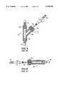
- FIGS. 1 through 4show that the current or conventional way of introducing parenteral liquid solutions and/or blood and blood products into a patient is by the conventional gravity feeding system 10.
- the feeding system 10includes a container 12 that is either a bottle or bag for the parenteral solution, a tube 14 extending from the bottle or bag and connected to a Y-injection site 16 (piggyback or secondary Y-injection site), and a tube 18 from the Y-injection site 16 to a needle or catheter 20 which is inserted into a vein in the arm 22 of the patient.
- the vein-access needle or catheteris taped to the patient with adhesive tape 24 so that the chance of a detachment and disconnect from the vein is minimized.
- Supplemental intravenous therapy from a piggyback or secondary bottle or bag 26is introduced through the Y-injection site 16 into the primary intravenous administration set 10.
- the Y-injection site 16which is integrated into the primary intravenous administration set 10 consists of two tubular conduits 16a, 16b which merge into a third tubular conduit 16c.
- the tubing 12 from the bottle or bag of parenteral solution of the primary intravenous administration set 10is attached into the inlet port 16a of the Y-injection site.
- the tube 18is attached into the exit port 16c of the Y-injection site.
- a sealed entry port segment 17 of the Y-injection site 16is provided by the extension conduit 16b which has a standard, self-sealing latex rubber septum 17a at its inlet port to seal this port from leakage. Consequently, it is difficult for pathogens to enter the Y-injection site 16 via the septum port 17 because of the seal 17a.
- This self-sealing septum 17ais of a conventional design and includes coaxial annular aprons which fit over the conduit wall and grip the external and internal wall surfaces to hold the septum securely to the conduit 16b.
- a plastic shrink-band(not shown) is shrunk on the outer wall of the septum 17a to securely connect it to the extension conduit 16b.
- the supplemental intravenous solutionis introduced into the primary intravenous administration set 10 through the Y-injection site 16 by way of a primed piggyback or secondary intravenous set 26.
- the piggyback or secondary intravenous set 26has a hollow-bore needle 28 attached to its distal end, which in turn is inserted through the self-sealing septum 17a of the Y-injection site 16 and into the extension conduit 16b.
- This needle 28is connected to a tube 30 which is connected to a drip-chamber (not shown) of the piggyback or secondary intravenous set 26.
- a roller clamp 14a, 30ais typically used on both the primary and piggyback/secondary intravenous sets to control liquid flow rates into the patient.
- the exposed needle 28is contaminated with pathogens and must be safely disposed by the clinicians without accidentally sticking themselves.
- the needle of the piggyback or secondary intravenous setmay be taped to the Y-injection site and extension port.
- the needlemay be secured from detachment, but the needle cannot be easily and safely removed by the clinician when the supplemental pharmaceutical therapy is completed, thereby creating a higher incidence for an accidental needle stick injury.
- clinicianshold the Y-injection site with one hand while the other hand is used to insert the needle into the Y-injection site septum, the clinicians may accidentally stick the needle directly into their hands holding the Y-injection site, or stick the needle completely through the Y-injection site wall into their hands.
- a heparin lock injection port 40is either connected directly to the vein-access device 20, or attached to a short catheter extension tubing set 42 typically with microbore tubing which is attached to the vein-access device as shown in FIG. 2.
- the heparin lockhas a self-sealing septum port 44 which is similar to the septum port 17 described above.
- a conventional intermittent intravenous therapycould utilize a short-term primary intravenous administration set 26 with a hollow-bore needle 28 attached to the distal end of a tube 30.
- the needlewould be inserted to the self-sealing septum found on standard heparin lock injection port 40.
- Another means of introducing supplemental intermittent pharmaceuticals to a patientis to perform an intravenous push utilizing a syringe with a hollow-bore needle attached. The drug is pushed into the patient through the heparin lock injection port 40. Once dispensed, the syringe/contaminated needle is removed from the self-sealing septum 44 on the heparin lock injection port 40.
- the common medical techniques for delivering supplemental liquid fluids to the patientnecessitates the use of a hollow-bore needle.
- the needleis either attached to a secondary intravenous set or a syringe, and is inserted through the self-sealing rubber stopper on the heparin lock injection port or the Y-injection port that is integrated into the primary intravenous administration set.
- the needleis secured to the injection port only with tape.
- the needlecan detach from the injection port resulting in a serious or fatal interruption of the flow of the intravenous solutions to the patient.
- the exposed needlecan easily be contaminated by contact with non-sterile objects. Sound aseptic techniques must be practiced by the healthcare professional in order to ensure that the sterile needle does not become contaminated and cause a nosocomial infection to the patient.
- Needleless valvesare known in the art of intravenous administration.
- My prior U.S. Pat. No. 5,395,348discloses a needleless intravenous quick connect/disconnect assembly which includes a first cylindrical member having a female luer connector extending from one end and providing a fluid path to the interior of the first cylindrical member, wherein a first seat is formed in the first cylindrical member at the junction of the female luer and the cylindrical opening; a second cylindrical member having a male-luer connector extending from one end and providing a fluid path to the interior of the second cylindrical member, wherein a second seat is formed in the second cylindrical member at the junction of the male-luer and the cylindrical opening; and a valve member having an integral stem, sealing surface, and resilient one-piece body.
- the stem of the resilient valve memberextends into the female luer from the inside of the first cylindrical member, and the resilient body of the valve member engages the second seat in the second cylindrical member and biases the sealing surface against the first seat in the first cylindrical member, thereby blocking fluid communication between the female-luer and the interior of the first cylindrical member.
- the integral valve memberis a stepped diameter cylinder having a hollow body and solid stem. The body has a larger diameter than the stem and the step between the body and the stem is frustroconical wherein the sealing surface is formed. The end of the stem is provided with a diametrical slot. An annular fluid passage exists between the valve member body and the cylindrical members.
- the second seatis preferably formed from a plurality of radially arranged vanes which enter the hollow body of the valve member and flare outward from it. Spaces between the vanes provide a fluid passage from the male-luer to the annular fluid passage surrounding the valve member body.
- Fluidis free to pass from the male luer through the diametrical slot in the valve member stem, out into the first cylindrical member, around the sealing ring, into the annular fluid passage surrounding the valve member body, through the spaces between the radial vanes, and through the male luer connector in the second cylindrical member.
- the resilient body of the valve memberbiases the valve stem back into the female-luer connector and thereby moves the sealing surface against the first seat, closing the valve.
- the valve memberinhibits optimal performance of a needleless valve during intravenous and blood collection applications in several ways. Due to the variations of male luer connectors around the world, the one-piece resilient valve stem member can restrict fluid-flow, and the variation of fluid flow from one connector to another can resultingly be unacceptable. Further, the hollow body of the one-piece valve member does not permit optimal blood flushing of the valve, as the hollow body has an open end or concavity in which fluid may accumulate without passing along the flow-stream through the connector.
- medical intravenous administration connectorswhich include a first coupling member having a female luer, a valve member having a substantially rigid stem and a substantially resilient body with a sealing surface, and a second coupling member having a fluid coupling extending from one end and an internal valve member support.
- the coupling membersare structured to couple to each other with the valve member being biased to a closed position. When assembled, the valve stem extends into the female luer, and the valve body biases the sealing surface against an annular ring in the first coupling member thereby blocking fluid communication.
- vanesare provided in the second coupling member on which the resilient body of the valve sits, with the vanes acting as a centering mechanism for the valve.
- the valvemay be opened for fluid flow through the assembly by coupling a male luer to the female luer of the assembly, or by pressure actuation.
- the connectorsare easy to prime, limit priming volume, and are arranged without dead-spaces in which blood can be trapped. However, even with these advantages, it is still beneficial to improve the connectors by simplifying the manufacture of the connectors and enhancing their fluid flow performance.
- Another object of the inventionis to provide both luer activated and fluid pressure activated medical intravenous line connectors which have good blood flushing characteristics.
- a further object of the inventionis to provide a medical IV line connector having a resilient valve member which is designed without "dead” spaces in which fluids may become entrapped.
- An additional object of the inventionis to provide luer activated medical intravenous line connectors with reduced priming volume relative to prior art luer activated medical intravenous line connectors.
- a further object of the inventionis to provide medical intravenous line connectors having components which are easily substituted during manufacture to provide either luer activated connectors or fluid pressure activated connectors.
- Yet another object of the inventionis to provide medical intravenous line connectors which are resistent to leaking even up to one hundred activations.
- Still another object of the inventionis to provide a medical IV line connector having a resilient valve member with means for repeatedly centering the valve relative to a sealing ring.
- Yet another object of the inventionis to provide a medical IV line connector where debubbling is simply achieved.
- a needleless IV line connector assemblygenerally comprises: a first coupling member having a female luer connector (preferably a luer lock) with a fluid path therethrough, a flange having a first sealing ring seat formed therein and a first mating means; a second coupling member having a male luer connector (preferably a luer lock) extending from one end and providing a fluid path therethrough, the second coupling member having a second mating means; and a valve member including a valve stem and a resilient valve body having an annular sealing surface.
- a valve body seatis formed in the interior of the second coupling member by a plurality of radially arranged stepped vanes which extend substantially the entire length of the second coupling member above the male luer.
- the presently preferred valve bodyis substantially frustroconical tapering in diameter toward the male luer and having a relatively broad end with a stepped axial bore defining the annular sealing surface.
- the presently preferred valve stemhas a stepped cylindrical portion which fits into the axial bore of the valve body and a pair of spaced apart upstanding members which extend into the female luer.
- the upstanding memberspreferably have curved outer surfaces and chamfered edges. A pair of inclined surfaces meet at a peak between the upstanding members and ramp outward toward the cylindrical portion of the valve stem.
- the first embodiment of the connector assemblyis assembled by snapping the stepped cylindrical portion of the valve stem to the stepped bore of the valve body, placing the valve body in the valve body seat of the second coupling member, placing the first coupling member over the valve stem so that the stem enters the female luer and the mating means on the flange on the first coupling member mates with the mating means of the second coupling member. While applying axial pressure to join the coupling members, sonic energy is applied to weld the mating means and hence the members together. Under the influence of sonic energy, the mating means melt at their point of contact and move towards each other to form a strong fluid-tight fusion. As assembled in this fashion, the valve body is stabilized, centered, and biased towards the first sealing ring.
- the length of the female luer and/or the length of the upstanding members of the valve stemis chosen so that when a male luer is inserted into the female luer, the valve stem is pushed towards the male luer of the assembly thereby compressing the valve body by moving the sealing surface of the valve body away from the first seat.
- the inclined surfaces of the valve stemmove at least partially inside the interior of the second coupling member. Fluid is thus free to pass through the space between the upstanding members of the valve stem along the inclined surfaces of the valve stem, through the spaces between the radial vanes, and through the male luer connector of the assembly.
- valve memberWhen opened, the valve member allows fluid flow in either direction, from the male luer to the female luer of the assembly or vice versa.
- the resilient valve bodyWhen a male luer is withdrawn from the female luer connector, the resilient valve body expands and biases the valve stem back into the female luer connector and also moves the sealing surface against the first seat, closing the valve.
- the valve memberincludes a substantially frustroconical valve body having a knob or hemispherical bump on one end defining the annular sealing surface. No valve stem is used in the second embodiment, but the connector assembly is otherwise the same and is assembled in the same manner as the first embodiment.
- fluid passing through the male luer with sufficient pressurecauses the valve member to compress and move away from the sealing surface and allow the fluid to flow through the spaces between the radial vanes, and through the male luer connector of the assembly.
- the valve memberexpands and moves the sealing surface against the first seat, closing the valve.
- the valve memberonly allows fluid flow from the female luer to the male luer but not vice versa.
- the valve memberincludes a resilient core which is insert molded in a relatively hard plastic frustroconical body.
- the resilient corehas a substantially I-shaped cross section with a knob or hemispherical bump on one end defining an annular sealing surface.
- the relatively hard plastic frustroconical bodydefines an annular stopping surface surrounding the annular sealing surface of the resilient core which lies adjacent the flange of the female luer. Under extreme backpressure conditions (e.g., 1200 psi), the stopping surface prevents the valve member from being forced out of the connector assembly through the female luer.
- the second coupling membermay be formed as a Y-site adapter rather than a male luer lock
- the third embodimentmay be formed as a multiple access manifold coupled to a plurality of first coupling members and valve members.
- FIG. 1is a schematic view of a prior art intravenous administration set coupled to a patient
- FIG. 2is a view similar to FIG. 1 of a prior art "intermittent" intravenous administration set coupled to a patient;
- FIG. 3is a broken side elevation view, in partial section, of a prior art Y-injection site
- FIG. 4is a broken side elevation view, in partial section, of a prior art heparin lock injection port
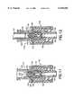
- FIG. 5is an exploded perspective view of a first embodiment of the invention.
- FIG. 6is an exploded sectional view taken along line 6--6 in FIG. 5;
- FIG. 7is a top plan view of the first coupling member of FIGS. 5 and 6;
- FIG. 8is a top plan view of the valve stem of FIGS. 5 and 6;
- FIG. 9is a top plan view of the valve body of FIGS. 5 and 6;
- FIG. 10is a top plan view of the second coupling member of FIGS. 5 and 6;
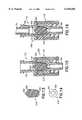
- FIG. 11is an assembled sectional view of the embodiment of FIGS. 5-10;
- FIG. 12is a view similar to FIG. 11 with an attached male luer forcing the valve member in the open position;
- FIG. 13is a sectional view of a valve member according to a second embodiment of the invention.
- FIG. 14is a top plan view of the valve member of FIG. 13;
- FIG. 15is an assembled sectional view of a second embodiment of the invention utilizing the valve member of FIGS. 13 and 14;
- FIG. 16is a view similar to FIG. 15 with an attached male luer showing the action of fluid pressure on the valve member;
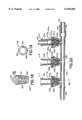
- FIG. 17is an exploded sectional view of a Y-site adapter according to the invention.
- FIG. 18is a sectional view of a valve member according to a third embodiment of the invention.
- FIG. 19is a top plan view of the valve member of FIG. 18.
- FIG. 20is an assembled sectional view of a third embodiment of the invention utilizing the valve member of FIGS. 18 and 19.
- a first embodiment of a connector assembly 100generally includes: a first coupling member 112, a valve stem 114, a resilient valve body 116, and a second coupling member 118.
- the first coupling member 112is a female luer connector (preferably a luer lock) 122 having a flange 124 from which extends a cylindrical mating means 125 with a tapered edge 125a.
- the female luer connector 122provides a fluid path 123 to the interior 126 of the cylindrical mating means 125.
- a first sealing ring seat 127is formed at the opening from the female luer into the cylindrical space 126.
- the valve stem 114has a cylindrical portion 136 with a circumferential flange 138, and an axial stabilizing pin 40 at one end and a pair of spaced apart upstanding members 137, 139 at the other end.
- the upstanding members 137, 139preferably have curved outer surfaces 137a, 139a and chamfered edges 137b, 137c, 139b, 139c.
- a pair of inclined surfaces 131, 133meet at a central peak 135 between the upstanding members 137, 139 and ramp downward and outward toward the cylindrical portion 136 of the valve stem 114.
- the angle defined by the central peak 135is approximately 69°.
- the resilient valve body 116is substantially frustroconical with a broader end serving as an annular sealing surface 150 and a narrower end 152.
- the annular surface 150is defined by an axial bore 142.
- the axial bore 142has a relatively large diameter portion 144 with an interior surface groove 146 and a relatively small diameter portion 148.
- the valve stem 114 and the valve body 116snap together as shown in FIGS. 11 and 12. More specifically, the portion 144 of the bore 142 in the valve body 16 receives the cylindrical portion 136 of the valve stem 114.
- the circumferential flange 138has a diameter slightly larger than the diameter of the portion 144 of the bore 142.
- the flange 138When the stem 114 is inserted into the body 116, the flange 138 stretches the resilient body 116 until the flange reaches the groove 146 in the bore 142.
- the groove 142has a diameter just slightly smaller than the diameter of the flange 138. The pieces snap together when the flange 138 embraces the groove 146, forcing the groove 146 to expand. This inhibits the pieces from separating.
- the axial stabilizing pin 140 of the valve stem 114is received by the small diameter portion 148 of the bore 142. It should be noted that length of the pin 140 is shorter than the length of the small diameter portion 148 of the bore 142.
- the second coupling member 118has a male luer connector (preferably a luer lock) 156 at one end and an open ended cylinder 158 at the other end.
- the male luer 156has an interior fluid path 160 which terminates in a valve body seat 162 inside the interior space 166 of the open ended cylinder 158.
- the valve body seat 162includes a plurality of substantially stepped vanes 162a-162d which extend substantially along the entire length of the interior 166 of the cylinder 158 above the male luer 156. These vanes serve the function of consistently centering the valve in the seat after activation (see FIGS. 11 and 12), such that no leakage is experienced even after numerous (e.g., one hundred) activations.
- annular channel mating means 170is provided at the end of the cylinder 158 and is dimensioned to receive the cylindrical mating means 125 of the first coupling member 112.
- the connector assembly 100 of FIGS. 5-12is assembled by inserting the stem 114 into the valve body 116 as described above, placing the body 116 of the valve member in the valve body seat 162 of the second coupling member 118, placing the first coupling member 112 over the valve stem 114 so that the stem enters the female luer 122 and the tapered edge 125a of the cylindrical mating means 125 rests inside the annular channel 170 of the second coupling member 118. While applying axial pressure to the first and second coupling members, the mating means and the first and second coupling members are welded by the application of sonic energy applied to weld the members together.
- valve body 116is stabilized, centered, and biased towards the first sealing ring 127.
- fluidis free to flow from the male luer 156 back to the female luer 122 and through the male luer 101.
- the resilient valve body 116expands and returns to the position shown in FIG. 11, sealing the valve so that no fluid can flow through the valve.
- the arrangement of the vanes and the valve bodypermits repeated use with accurate reseating of the valve and no leakage.
- the geometry of the valve body, the vanes, and the valve stemprovide very high flow rates with a very low priming volume.
- the valve designavoids the presence of any "dead space" where biological fluids can accumulate and provide a host for pathogens. The entire fluid path is easily flushed.
- the first coupling member 112 and the second coupling member 118are made of clear plastic so that the clinician can observe aspiration and flushing.
- the presently preferred material for both coupling members as well as for the valve stemis BASF TERLUX #2802TR clear ABS.
- the presently preferred material for the resilient valve bodyis WACKER ELASTOSIL #LR-3003-50.
- a second (fluid activated) embodiment of a connector assembly 200utilizes the same first and second coupling members 112, 118, but with a different valve member 216.
- the valve member 216is comprised of a unitary resilient valve body, but does not include a valve stem.
- the valve bodyis substantially frustroconical with a broad end serving as a sealing surface 250 and a narrow end 252.
- the broad endalso includes a centrally located dome 242 around which the annular sealing surface 250 is located.
- the valve body 216does not utilize a valve stem.
- the connector assembly 200is assembled in substantially the same manner as the connector assembly 100 described above, except that no assembly of the valve body and stem is required. When the connector is assembled as shown in FIG.
- valve body 216is biased between the vanes of the coupling member 118 and the sealing ring 127 of the connector member 112.
- the dome 242 on the valve body 216resides at the distal end of the female luer 122.
- the valve member 216does not move and the fluid passage between the female luer 122 and the male luer 156 of the connector assembly 200 remains closed.
- fluid pressureacts upon the dome 242 and the annular surface 250 to compress the valve member 216 as shown in FIG. 16. This opens a passageway from the female luer 122 to the male luer 156.
- valve member 216will remain in this open position so long as fluid pressure is applied through the male luer 101. When pressure ceases, the valve member 216 will return to the closed position shown in FIG. 15. It will therefore be appreciated that according to this embodiment of the invention, fluid flow from the male luer 156 to the female luer 122 is virtually impossible as a pressure change to effect such flow will cause the valve member 216 to return to the closed position.
- the connector assembly 200provides the same advantages of low priming volume and high flow rate as the connector assembly 100 described above. While the valve member 216 is shown with a dome 242, the dome is not necessarily essential to the concept of the invention. The dome is preferred because it provides a greater surface area upon which fluid may act to compress the valve member. The presence of the dome, therefore allows the valve to be opened with a lower fluid pressure than would be required to open the valve without a dome. In addition, while the dome has been shown as an integral part of the valve body 216, a separate stem-like dome member could be inserted into the valve body 116 in the manner shown in FIGS. 5 and 6.
- FIG. 17shows a Y-site connector 300 based on the connector 100 described above.
- the Y-site connector 300utilizes a first coupling member 112, a valve stem 114, a valve body 116, and a Y-site second coupling member 318 which replaces the second coupling member 118 shown in FIGS. 5 and 6.
- the end of the Y-site adapter 318 which couples with the first coupling member 112 and receives the valve body 116is substantially the same as the second coupling member 118 described above.
- the other end of the Y-site adaptor 318is provided with two fluid connectors 356, 357 which provide fluid paths in communication with each other as well as with the interior 366 of the coupling member 318.
- the Y-site connector 300is assembled in substantially the same manner as the connector 100 described above.
- a valve body 316includes a resilient core 341 which is insert molded in a relatively hard plastic frustroconical body 343.
- the core 341is made of silicone and the body 343 is made of polycarbonate.
- the resilient core 341has a substantially I-shaped cross section with a knob or hemispherical bump 342 on one end defining an annular sealing surface 350.
- the other end 352 of the core 341forms the narrow lower end of the valve body 316.
- the relatively hard plastic frustroconical body 343defines an annular stopping surface 345 surrounding the annular sealing surface 350 of the resilient core 341.
- the overall shape and dimensions of the valve body 316are substantially the same as those of the valve body 216 described above and the valve body 316 may be substituted for the valve body 216 in the connectors 200 or 300 described above.
- the relative dimensions of the resilient insert 341 and the outer body 343are such that, when installed in a connector (e.g. 200 in FIGS. 15 and 16), the annular sealing surface 350 engages the sealing ring 127 (FIG. 15 and 16) in the same manner as the sealing surface 250 of valve body 216.
- the relative location of the stopping surface 345is such that it lies outside the sealing ring adjacent to the lower surface of the flange 124 of the first coupling member 112. As shown in FIG. 18, the surface 350 is slightly raised above the surface 345.
- the surface 350is approximately 0.005-0.010 inch higher than the surface 345.
- the advantage of the hard stopping surface 345is best understood with reference to FIG. 20 wherein the valve body 316 is utilized in a multiple access manifold 400.
- a multiple access manifold 400includes a body 402 having a throughbore 404 with a male luer 456 at one end thereof and a female luer 422 at the other end thereof.
- Three coupling member-valve body assemblies (A-C)are arranged along the manifold body 402 as shown.
- the manifold 400is often used in relatively high pressure applications. It has been discovered that when fluid under high pressure is applied to the female luer 422 (via a male luer 101), the back pressure created at the valve bodies 316a-316c is substantial. If the fully resilient valve body 216 (FIG.
- valve 13is used in a manifold assembly of this type, high back pressure can cause the valve bodies to be forced into the female luers 122a-122c and under extremely high pressure, the valve bodies can be blown out of the manifold.
- the hard stopping surface 345prevents the valve body from entering the female luer and also prevents the sealing ring from damaging the sealing surface 350 of the resilient portion of the valve body 316.
- the resilient portion 341a of the valve member 316ais compressed under the influence of fluid pressure entering via the luer 103 (which pressure is greater than the pressure of fluid entering through luer 101).
- the annular sealing surface 350a of the valve member 316ais moved away from the sealing ring 127a of the coupling member 112a and allows fluid to flow as described hereinabove. If the fluid introduced via the luer 101 (or via the luer 103) is under high pressure and significant back pressure is created at the valve members 316b, 316c (and 316a if no pressure is applied through luer 103), the hard stopping surfaces 345b, 345c, (345a) will abut the inner surfaces of the flanges 124b, 124c, (124a) and prevent the valve members 316b, 316c, (316a) from being forced out into the female luers 122b, 122c (122a).
- IV fluidis intended to be understood in a broad sense to include blood, blood products, dyes, or other fluids and the term “administration” is used in its broad sense to include the dispensing or collection of the "IV fluid”.
- the connectorsare illustrated as preferably having a female luer lock on one end, and a male luer lock on the other end, it will be appreciated that, although not preferred, simple luer slips could be utilized in lieu of luer locks.
- valve member seathas been disclosed as having four radial vanes, it will be understood with the benefit of the instant disclosure that the essence of the valve member seat is to provide a stable support and centering for the valve member body while also providing a fluid path into the male luer. Other types of valve member seats having these features could be substituted without departing from the spirit of the invention.
Landscapes
- Health & Medical Sciences (AREA)
- Engineering & Computer Science (AREA)
- Heart & Thoracic Surgery (AREA)
- General Engineering & Computer Science (AREA)
- Public Health (AREA)
- Life Sciences & Earth Sciences (AREA)
- Animal Behavior & Ethology (AREA)
- General Health & Medical Sciences (AREA)
- Veterinary Medicine (AREA)
- Pulmonology (AREA)
- Anesthesiology (AREA)
- Biomedical Technology (AREA)
- Hematology (AREA)
- Mechanical Engineering (AREA)
- Pharmacology & Pharmacy (AREA)
- Infusion, Injection, And Reservoir Apparatuses (AREA)
Abstract
Description
Claims (8)
Priority Applications (1)
| Application Number | Priority Date | Filing Date | Title |
|---|---|---|---|
| US09/344,403US6158458A (en) | 1995-12-29 | 1999-06-24 | Medical intravenous administration line connectors having a luer or pressure activated valve |
Applications Claiming Priority (3)
| Application Number | Priority Date | Filing Date | Title |
|---|---|---|---|
| US08/581,057US5788215A (en) | 1995-12-29 | 1995-12-29 | Medical intravenous administration line connectors having a luer or pressure activated valve |
| US08/841,281US5954313A (en) | 1995-12-29 | 1997-04-29 | Medical intravenous administration line connectors having a luer activated valve |
| US09/344,403US6158458A (en) | 1995-12-29 | 1999-06-24 | Medical intravenous administration line connectors having a luer or pressure activated valve |
Related Parent Applications (1)
| Application Number | Title | Priority Date | Filing Date |
|---|---|---|---|
| US08/841,281DivisionUS5954313A (en) | 1995-12-29 | 1997-04-29 | Medical intravenous administration line connectors having a luer activated valve |
Publications (1)
| Publication Number | Publication Date |
|---|---|
| US6158458Atrue US6158458A (en) | 2000-12-12 |
Family
ID=25284486
Family Applications (2)
| Application Number | Title | Priority Date | Filing Date |
|---|---|---|---|
| US08/841,281Expired - LifetimeUS5954313A (en) | 1995-12-29 | 1997-04-29 | Medical intravenous administration line connectors having a luer activated valve |
| US09/344,403Expired - LifetimeUS6158458A (en) | 1995-12-29 | 1999-06-24 | Medical intravenous administration line connectors having a luer or pressure activated valve |
Family Applications Before (1)
| Application Number | Title | Priority Date | Filing Date |
|---|---|---|---|
| US08/841,281Expired - LifetimeUS5954313A (en) | 1995-12-29 | 1997-04-29 | Medical intravenous administration line connectors having a luer activated valve |
Country Status (3)
| Country | Link |
|---|---|
| US (2) | US5954313A (en) |
| AU (1) | AU7269898A (en) |
| WO (1) | WO1998049476A1 (en) |
Cited By (49)
| Publication number | Priority date | Publication date | Assignee | Title |
|---|---|---|---|---|
| US20020111645A1 (en)* | 2001-02-15 | 2002-08-15 | Scimed Life System, Inc. | Vacuum prep catheter |
| WO2003083335A1 (en)* | 2002-03-22 | 2003-10-09 | Halkey-Roberts Corporation | Disc check valve |
| US20040039341A1 (en)* | 2002-08-22 | 2004-02-26 | Ranalletta Joseph V. | Protective cap and capping method for medical male luer fittings |
| US20040039374A1 (en)* | 2002-08-22 | 2004-02-26 | Gerry Tighe | Sterile docking apparatus and method |
| US20040138626A1 (en)* | 1996-11-18 | 2004-07-15 | Cote Andrew L. | Luer-activated valve |
| US6908459B2 (en) | 2001-12-07 | 2005-06-21 | Becton, Dickinson And Company | Needleless luer access connector |
| US20050142013A1 (en)* | 2001-12-17 | 2005-06-30 | Faries Durward I.Jr. | Method and apparatus for heating solutions within intravenous lines to desired temperatures during infusion |
| US20060157971A1 (en)* | 2005-01-14 | 2006-07-20 | Baldwin Brian E | Swabable fluid connectors and fluid connector pairs |
| US20060184140A1 (en)* | 2003-07-09 | 2006-08-17 | Jms Co, Ltd | Mixture injection port |
| US20060259013A1 (en)* | 2005-05-10 | 2006-11-16 | Ranalletta Joseph V | Sterile docking apparatus and method |
| WO2006039501A3 (en)* | 2004-09-30 | 2007-01-25 | Univ Northeastern | Hydrocephalus shunt system quick connector assembly |
| US20070083157A1 (en)* | 2005-10-11 | 2007-04-12 | Belley Richard A | IV catheter with in-line valve and methods related thereto |
| US20070100295A1 (en)* | 2005-10-11 | 2007-05-03 | Belley Richard A | IV catheter with in-line valve and methods related thereto |
| US20070106243A1 (en)* | 2005-10-27 | 2007-05-10 | Faries Durward I Jr | Method and apparatus to indicate prior use of a medical item |
| US20070179474A1 (en)* | 2005-12-29 | 2007-08-02 | Cahill Ryan J | Syringe activated-valve for flushing a catheter and methods thereof |
| US20080082082A1 (en)* | 2006-09-29 | 2008-04-03 | Carlyon James L | Surgical fluid transfer apparatus |
| US20080091173A1 (en)* | 2005-10-11 | 2008-04-17 | Belley Richard A | IV catheter with in-line valve and methods related thereto |
| US20080147016A1 (en)* | 1997-03-03 | 2008-06-19 | Faries Durward I | Method and Apparatus for Pressure Infusion and Temperature Control of Infused Liquids |
| USD571912S1 (en) | 2006-05-10 | 2008-06-24 | Baxa Corporation | Medical connector docking device |
| US7392638B2 (en) | 2000-08-10 | 2008-07-01 | Baxa Corporation | Method, system, and apparatus for handling, labeling, filling, and capping syringes with improved cap |
| US20080205481A1 (en)* | 2007-02-22 | 2008-08-28 | Faries Durward I | Method and Apparatus for Measurement and Control of Temperature for Infused Liquids |
| US20080214990A1 (en)* | 2007-03-02 | 2008-09-04 | Smith & Nephew, Inc. | Fluid Conduit Connection |
| US20080275354A1 (en)* | 2007-04-11 | 2008-11-06 | Naveen Thuramalla | System and method for diverting flow to facilitate measurement of system parameters |
| US20090163876A1 (en)* | 2007-12-20 | 2009-06-25 | Tyco Healthcare Group Lp | Cap Assembly for Use With a Prefilled Lock Solution Syringe |
| US20090256101A1 (en)* | 2008-04-09 | 2009-10-15 | Hatton Jason D | Valve Assembly |
| US7635357B2 (en) | 1994-06-20 | 2009-12-22 | Mayer Bruno Franz P | Needleless injection site |
| US7666166B1 (en)* | 2004-12-27 | 2010-02-23 | Blivic, Llc | Bloodless intravenous integrated catheter |
| US20100318039A1 (en)* | 2007-12-20 | 2010-12-16 | Smith & Nephew Plc | Connectors |
| US7887519B2 (en) | 2005-01-14 | 2011-02-15 | Nypro Inc. | Valve with internal lifter |
| US20110092784A1 (en)* | 2009-07-20 | 2011-04-21 | Optiscan Biomedical Corporation | Adjustable connector and dead space reduction |
| US20110130724A1 (en)* | 2008-09-05 | 2011-06-02 | Carefusion 303, Inc. | Neonatal luer-activated medical connector |
| US8353869B2 (en) | 2010-11-02 | 2013-01-15 | Baxa Corporation | Anti-tampering apparatus and method for drug delivery devices |
| US8487738B2 (en) | 2006-03-20 | 2013-07-16 | Medical Solutions, Inc. | Method and apparatus for securely storing medical items within a thermal treatment system |
| US8568371B2 (en) | 2009-06-22 | 2013-10-29 | Np Medical Inc. | Medical valve with improved back-pressure sealing |
| US8731639B2 (en) | 2009-07-20 | 2014-05-20 | Optiscan Biomedical Corporation | Adjustable connector, improved fluid flow and reduced clotting risk |
| US8821011B2 (en) | 1999-03-30 | 2014-09-02 | Medical Solutions, Inc. | Method and apparatus for monitoring temperature of intravenously delivered fluids and other medical items |
| US8845586B2 (en)* | 2004-03-09 | 2014-09-30 | Patented Medical Solutions Llc | Method and apparatus for facilitating injection of medication into an intravenous fluid line while maintaining sterility of infused fluids |
| US9119912B2 (en) | 2001-03-12 | 2015-09-01 | Medical Solutions, Inc. | Method and apparatus for controlling pressurized infusion and temperature of infused liquids |
| US9138572B2 (en) | 2010-06-24 | 2015-09-22 | Np Medical Inc. | Medical valve with fluid volume alteration |
| US9211381B2 (en) | 2012-01-20 | 2015-12-15 | Medical Solutions, Inc. | Method and apparatus for controlling temperature of medical liquids |
| US9308051B2 (en) | 2011-11-15 | 2016-04-12 | Smiths Medical Asd, Inc. | Illuminated tubing set |
| US9308323B2 (en) | 2011-11-15 | 2016-04-12 | Smiths Medical Asd, Inc. | Systems and methods for illuminated medical tubing detection and management indicating a characteristic of at least one infusion pump |
| US20170122443A1 (en)* | 2015-11-03 | 2017-05-04 | Stoma Ventures, LLC | Disposable dental valve device |
| US9656029B2 (en) | 2013-02-15 | 2017-05-23 | Medical Solutions, Inc. | Plural medical item warming system and method for warming a plurality of medical items to desired temperatures |
| US10426929B2 (en)* | 2017-07-19 | 2019-10-01 | Becton, Dickinson And Company | Integrated peripheral intra-venous catheter with improved extension tube port probe access |
| EP2593167B1 (en)* | 2010-07-15 | 2020-10-21 | Becton, Dickinson and Company | Systems for providing a flushable catheter assembly |
| US11311664B1 (en)* | 2021-04-12 | 2022-04-26 | Denicia Dread Rankin | Shapeable intravenous tubing |
| US20230226340A1 (en)* | 2020-06-24 | 2023-07-20 | Cyto365 Ab | A closed-system type female connector, a method for manufacture, and a stopcock having such female connectors |
| USD1010112S1 (en) | 2021-07-03 | 2024-01-02 | KAIRISH INNOTECH Private Ltd. | Vial adapter with valve |
Families Citing this family (43)
| Publication number | Priority date | Publication date | Assignee | Title |
|---|---|---|---|---|
| FI111319B (en) | 1999-06-21 | 2003-06-30 | Nokia Corp | Procedure for connecting the connection and radio system |
| US6641556B1 (en)* | 1999-07-06 | 2003-11-04 | Respiratory Support Products, Inc. | Intravenous fluid heating system |
| IT1311347B1 (en)* | 1999-11-12 | 2002-03-12 | Borla Ind | CHECK VALVE FOR MEDICAL INFUSION LINES AND SIMILAR. |
| DE10196262T1 (en)* | 2000-05-31 | 2003-05-15 | Honeywell Int Inc | filling system |
| US6695817B1 (en) | 2000-07-11 | 2004-02-24 | Icu Medical, Inc. | Medical valve with positive flow characteristics |
| JP4996015B2 (en)* | 2001-03-12 | 2012-08-08 | メディキット株式会社 | Indwelling catheter |
| US8562583B2 (en)* | 2002-03-26 | 2013-10-22 | Carmel Pharma Ab | Method and assembly for fluid transfer and drug containment in an infusion system |
| US20040073171A1 (en) | 2002-10-10 | 2004-04-15 | Rogers Bobby E. | Needle-free valve and catheter assembly |
| US20040181192A1 (en)* | 2003-03-11 | 2004-09-16 | Cuppy Michael John | Vascular access device and method of using same |
| US7226434B2 (en) | 2003-10-31 | 2007-06-05 | Tyco Healthcare Group Lp | Safety shield |
| US7988664B2 (en) | 2004-11-01 | 2011-08-02 | Tyco Healthcare Group Lp | Locking clip with trigger bushing |
| US8636721B2 (en) | 2003-11-20 | 2014-01-28 | Henry M. Jackson Foundation For The Advancement Of Military Medicine, Inc. | Portable hand pump for evacuation of fluids |
| EP2286863A3 (en) | 2004-01-09 | 2011-03-23 | Corazon Technologies, Inc. | Multilumen catheters and methods for their use |
| US8337475B2 (en) | 2004-10-12 | 2012-12-25 | C. R. Bard, Inc. | Corporeal drainage system |
| US20060161115A1 (en) | 2004-11-05 | 2006-07-20 | Fangrow Thomas F | Soft-grip medical connector |
| US7648491B2 (en)* | 2005-05-13 | 2010-01-19 | Bob Rogers | Medical substance transfer system |
| BRPI0717401A2 (en) | 2006-10-25 | 2013-11-12 | Icu Medical Inc | CONNECTOR FOR MEDICAL USE |
| WO2009042874A1 (en) | 2007-09-27 | 2009-04-02 | Tyco Healthcare Group Lp | I.v. catheter assembly and needle safety device |
| CA2739661C (en)* | 2007-10-19 | 2016-08-02 | Infusion Innovations, Inc. | Devices and assemblies for controlling fluid flow |
| DE602008002806D1 (en) | 2007-12-20 | 2010-11-11 | Tyco Healthcare | Locking cap arrangement with spring-loaded collar |
| JP5273473B2 (en)* | 2008-09-12 | 2013-08-28 | 株式会社ジェイ・エム・エス | Spout and liquid container with spout |
| JP5310731B2 (en)* | 2008-10-16 | 2013-10-09 | 株式会社ジェイ・エム・エス | Spout and liquid container with spout |
| US8454579B2 (en) | 2009-03-25 | 2013-06-04 | Icu Medical, Inc. | Medical connector with automatic valves and volume regulator |
| USD644731S1 (en) | 2010-03-23 | 2011-09-06 | Icu Medical, Inc. | Medical connector |
| US8758306B2 (en) | 2010-05-17 | 2014-06-24 | Icu Medical, Inc. | Medical connectors and methods of use |
| US8684331B2 (en) | 2011-05-11 | 2014-04-01 | Bioflo, Llc | Valve for regulating the flow of a liquid |
| CN202302077U (en)* | 2011-08-23 | 2012-07-04 | 黄丹瑜 | Medical valve inside |
| JP6370364B2 (en) | 2013-03-15 | 2018-08-08 | アイシーユー・メディカル・インコーポレーテッド | Medical connector |
| AU2014364218B2 (en) | 2013-12-11 | 2019-06-06 | Icu Medical, Inc. | Check valve |
| DE102014103489A1 (en)* | 2014-03-14 | 2015-09-17 | Fresenius Medical Care Deutschland Gmbh | Check valve assembly, medical functional device and a blood treatment device |
| EP3218044B1 (en) | 2014-11-12 | 2024-04-03 | Fresenius Kabi Deutschland GmbH | Needleless, intermittent, neutral displacement iv injection port |
| USD786427S1 (en) | 2014-12-03 | 2017-05-09 | Icu Medical, Inc. | Fluid manifold |
| USD793551S1 (en) | 2014-12-03 | 2017-08-01 | Icu Medical, Inc. | Fluid manifold |
| US9592353B2 (en)* | 2015-04-30 | 2017-03-14 | Sanjay K Roy | Adaptor/tubing with alarm(s) |
| WO2017027885A1 (en)* | 2015-08-13 | 2017-02-16 | Site Saver, Inc. | Breakaway connector |
| WO2018017365A1 (en) | 2016-07-18 | 2018-01-25 | Merit Medical Systems, Inc. | Inflatable radial artery compression device |
| US9925365B1 (en) | 2017-06-21 | 2018-03-27 | Rymed Technologies, Llc | Needleless IV injection port |
| USD851759S1 (en) | 2018-01-17 | 2019-06-18 | Site Saver, Inc. | Breakaway connector for medical lines |
| ES2989232T3 (en) | 2018-01-19 | 2024-11-25 | Site Saver Inc | Detachable medical tube connector |
| CN113015510B (en) | 2018-10-03 | 2025-01-10 | 武田药品工业株式会社 | Packaging for multiple containers |
| WO2020072230A2 (en) | 2018-10-03 | 2020-04-09 | Baxalta GmbH | Pooling device for single or multiple medical containers |
| US11857752B2 (en) | 2019-12-16 | 2024-01-02 | Rymed Technologies, Llc | High flow, needleless connector |
| US12426864B2 (en) | 2021-06-18 | 2025-09-30 | Merit Medical Systems, Inc. | Hemostasis devices and methods of use |
Citations (86)
| Publication number | Priority date | Publication date | Assignee | Title |
|---|---|---|---|---|
| US2106638A (en)* | 1932-04-30 | 1938-01-25 | F H Watson Company | Valve stem |
| US3192949A (en)* | 1962-07-10 | 1965-07-06 | Halkey Roberts Corp | Spring biased check valve |
| US3326521A (en)* | 1964-05-18 | 1967-06-20 | Ind Electronic Rubber | Needle valve |
| US3799171A (en)* | 1972-09-07 | 1974-03-26 | Kendall & Co | Inflation valve for catheter retention balloon |
| US3799132A (en)* | 1973-04-09 | 1974-03-26 | Ferry Cap Set Screw Co | Valve device and system employing the same |
| US3806086A (en)* | 1973-03-15 | 1974-04-23 | Nosco Plastics | Automatic shut-off valve for administration of sterile fluids |
| US3831629A (en)* | 1972-01-24 | 1974-08-27 | Halkey Roberts Corp | Check valve |
| US4103686A (en)* | 1977-03-29 | 1978-08-01 | Burron Medical Products, Inc. | Dual valve assembly |
| US4128098A (en)* | 1976-12-06 | 1978-12-05 | American Hospital Supply Corporation | Valved spike transfer device |
| US4349021A (en)* | 1980-06-09 | 1982-09-14 | Bentley Laboratories | Atraumatic blood access device valve |
| US4375825A (en)* | 1978-05-25 | 1983-03-08 | Greenspan Donald J | Integral valve apparatus |
| US4559043A (en)* | 1984-10-29 | 1985-12-17 | Drs Infusion Systems, Inc. | Assembly with septum fitting for connecting adaptor and fluid tube |
| US4617015A (en)* | 1984-08-10 | 1986-10-14 | Halkey-Roberts Corporation | Visual pressure indicator for endotracheal cuff |
| US4681132A (en)* | 1986-05-23 | 1987-07-21 | Halkey-Roberts Corporation | Check valve with preset cracking pressure |
| US4683916A (en)* | 1986-09-25 | 1987-08-04 | Burron Medical Inc. | Normally closed automatic reflux valve |
| US4723550A (en)* | 1986-11-10 | 1988-02-09 | Cordis Corporation | Leakproof hemostasis valve with single valve member |
| US4776369A (en)* | 1987-02-24 | 1988-10-11 | Halkey-Roberts Corporation | Check valve having snap-on clamping sleeve |
| US4781674A (en)* | 1987-01-30 | 1988-11-01 | Vir Engineering | Fluid flow control valve |
| US4908018A (en)* | 1987-06-24 | 1990-03-13 | John Thomsen | Method and apparatus for injecting fluids into an IV line |
| US4915687A (en)* | 1989-02-17 | 1990-04-10 | Sivert George A | Needleless injection port arrangement |
| US4934655A (en)* | 1989-03-13 | 1990-06-19 | Colder Products Company | Shutoff valve assembly |
| US5024657A (en)* | 1984-12-03 | 1991-06-18 | Baxter International Inc. | Drug delivery apparatus and method preventing local and systemic toxicity |
| US5060812A (en)* | 1990-09-06 | 1991-10-29 | International Medication Systems, Limited | Medication container stopper which can be punctured by nozzle of a hypodermic syringe |
| US5085645A (en)* | 1990-08-15 | 1992-02-04 | Becton, Dickinson And Company | Apparatus and method for a catheter adapter with valve |
| US5104093A (en)* | 1991-02-27 | 1992-04-14 | Robertshaw Controls Company | Fuel control device, valve member therefor and methods of making the same |
| US5108380A (en)* | 1990-01-12 | 1992-04-28 | B. Braun Melsungen Ag | Hub member |
| US5116021A (en)* | 1986-03-04 | 1992-05-26 | Deka Products Limited Partnership | Quick-disconnect valve |
| US5149054A (en)* | 1989-06-02 | 1992-09-22 | Perfection Corporation | Reinforced polymer valve |
| US5163922A (en)* | 1991-04-29 | 1992-11-17 | Charles E. McElveen, Jr. | Dual-valved connector for intravenous systems |
| US5181921A (en)* | 1990-05-25 | 1993-01-26 | Kaken Co., Ltd. | Detachable balloon with two self-sealing valves |
| US5181913A (en)* | 1987-03-09 | 1993-01-26 | Prn Services, Inc. | Catheter with check valve and rolled sheath |
| US5195967A (en)* | 1992-02-18 | 1993-03-23 | Nakao Naomi L | Anticlotting device and method for use with IV catheters |
| US5199947A (en)* | 1983-01-24 | 1993-04-06 | Icu Medical, Inc. | Method of locking an influent line to a piggyback connector |
| US5201725A (en)* | 1991-09-26 | 1993-04-13 | Ivac | Needle free i.v. adapter |
| US5203775A (en)* | 1990-09-18 | 1993-04-20 | Medex, Inc. | Needleless connector sample site |
| US5215538A (en)* | 1992-02-05 | 1993-06-01 | Abbott Laboratories | Connector-activated in-line valve |
| US5217434A (en)* | 1991-10-15 | 1993-06-08 | Scimed Life Systems, Inc. | Innerless dilatation catheter with balloon stretch valve |
| US5230706A (en)* | 1992-03-12 | 1993-07-27 | Duquette Irene A | Bi-directional valve assembly used in needleless injection or infusion ports |
| US5242423A (en)* | 1992-03-09 | 1993-09-07 | American Home Products Corporation | Needleless syringe |
| US5242393A (en)* | 1992-06-18 | 1993-09-07 | Becton, Dickinson And Company | Valved blunt cannula injection site |
| US5242432A (en)* | 1991-09-26 | 1993-09-07 | Ivac | Needleless adapter |
| US5250028A (en)* | 1989-02-15 | 1993-10-05 | Alza Corporation | Intravenous system for delivering a beneficial agent using permeability enhancers |
| US5250034A (en)* | 1990-09-17 | 1993-10-05 | E-Z-Em, Inc. | Pressure responsive valve catheter |
| US5251873A (en)* | 1992-06-04 | 1993-10-12 | Vernay Laboratories, Inc. | Medical coupling site |
| US5259839A (en)* | 1991-08-23 | 1993-11-09 | Scimed Life Systems, Inc. | Balloon catheter with guidewire valve |
| US5269771A (en)* | 1993-02-24 | 1993-12-14 | Thomas Medical Products, Inc. | Needleless introducer with hemostatic valve |
| US5280876A (en)* | 1993-03-25 | 1994-01-25 | Roger Atkins | Limited restriction quick disconnect valve |
| US5284475A (en)* | 1992-07-21 | 1994-02-08 | Mackal Glenn H | Luer valve adapter with expandable end |
| US5289849A (en)* | 1990-05-29 | 1994-03-01 | Paradis Joseph R | Control of fluid flow |
| US5290263A (en)* | 1989-02-02 | 1994-03-01 | Regents Of The University Of Minnesota | Bidirectional check valve catheter |
| US5300044A (en)* | 1991-09-26 | 1994-04-05 | Baxter International Inc. | Intravenous tube safety apparatus |
| US5300033A (en)* | 1992-07-09 | 1994-04-05 | Unisurge, Inc. | Introducer assembly and valve construction for use therein |
| US5308334A (en)* | 1990-12-27 | 1994-05-03 | Block Medical, Inc. | Closed system for iv site flush |
| US5322518A (en)* | 1991-04-27 | 1994-06-21 | B. Braun Melsungen Ag | Valve device for a catheter |
| US5330435A (en)* | 1993-04-08 | 1994-07-19 | Vaillancourt Vincent L | Valve for a catheter assembly |
| US5334170A (en)* | 1993-07-14 | 1994-08-02 | Abbott Laboratories | Dye management system including an administration set with an in-line burette |
| US5336192A (en)* | 1991-11-27 | 1994-08-09 | Palestrant Aubrey M | Self-sealing valve device for angiographic catheters |
| US5336174A (en)* | 1992-05-07 | 1994-08-09 | Ivac Corporation | Flow control valve |
| US5338313A (en)* | 1992-12-17 | 1994-08-16 | Thomas J. Fogarty, M.D. | Adjustable valve having a radially compressible sealing body |
| US5353837A (en)* | 1986-03-04 | 1994-10-11 | Deka Products Limited Partnership | Quick-disconnect valve |
| US5356375A (en)* | 1992-04-06 | 1994-10-18 | Namic U.S.A. Corporation | Positive pressure fluid delivery and waste removal system |
| US5360413A (en)* | 1991-12-06 | 1994-11-01 | Filtertek, Inc. | Needleless access device |
| US5364371A (en)* | 1986-03-04 | 1994-11-15 | Deka Products Limited Partnership | Intravenous fluid delivery device |
| US5370624A (en)* | 1993-09-14 | 1994-12-06 | Becton Dickinson And Company | Catheter with deactivatable side port |
| US5391150A (en)* | 1992-12-28 | 1995-02-21 | Richmond; Frank | IV bag with needleless connector ports |
| US5390898A (en)* | 1994-04-06 | 1995-02-21 | Habley Medical Technology Corporation | Needleless dual direction check valve |
| US5395348A (en)* | 1993-05-04 | 1995-03-07 | Symbiosis Corporation | Medical intravenous administration line connectors |
| US5399171A (en)* | 1991-06-10 | 1995-03-21 | Baxter International Inc. | Intravenous metering monitoring device |
| US5401255A (en)* | 1993-07-20 | 1995-03-28 | Baxter International Inc. | Multi-functional valve with unitary valving member and improved safety |
| US5405323A (en)* | 1994-02-22 | 1995-04-11 | Aeroquip Corporation | Catheter check valve assembly |
| US5425465A (en)* | 1993-03-03 | 1995-06-20 | Healy; Patrick M. | Valved medication container |
| US5429256A (en)* | 1994-01-24 | 1995-07-04 | Kestenbaum; Alan D. | Drug withdrawal system for container |
| US5433330A (en)* | 1992-08-07 | 1995-07-18 | The West Company, Incorporated | Needleless access stopper |
| US5464938A (en)* | 1990-04-09 | 1995-11-07 | Immunex Corporation | Isolated viral protein TNF antagonists |
| US5470319A (en)* | 1994-06-20 | 1995-11-28 | Critical Device Corporation | Needleless injection site |
| US5533983A (en)* | 1993-11-26 | 1996-07-09 | Haining; Michael L. | Valved medical connector |
| US5535771A (en)* | 1994-08-10 | 1996-07-16 | Becton, Dickinson And Company | Valved PRN adapter for infusion devices |
| US5535785A (en)* | 1994-09-08 | 1996-07-16 | Nypro, Inc. | Luer-activated check valve |
| US5573525A (en)* | 1993-12-28 | 1996-11-12 | Watson; Thomas L. | Bottle with closure element for receiving syringe and method therefor |
| US5578059A (en)* | 1993-11-30 | 1996-11-26 | Medex, Inc. | Anti-reflux valve with environmental barrier |
| US5618268A (en)* | 1995-06-06 | 1997-04-08 | B. Braun Medical Inc. | Medical infusion devices and medicine delivery systems employing the same |
| US5645538A (en)* | 1993-09-16 | 1997-07-08 | Richmond; Frank M. | Needleless valve for use in intravenous infusion |
| US5685866A (en)* | 1991-12-18 | 1997-11-11 | Icu Medical, Inc. | Medical valve and method of use |
| US5782816A (en)* | 1995-09-07 | 1998-07-21 | David R. Kipp | Bi-directional valve and method of using same |
| US5788215A (en)* | 1995-12-29 | 1998-08-04 | Rymed Technologies | Medical intravenous administration line connectors having a luer or pressure activated valve |
| US5833213A (en)* | 1995-12-29 | 1998-11-10 | Rymed Technologies, Inc. | Multiple dose drug vial adapter for use with a vial having a pierceable septum and a needleless syringe |
Family Cites Families (1)
| Publication number | Priority date | Publication date | Assignee | Title |
|---|---|---|---|---|
| US5465938A (en)* | 1990-05-29 | 1995-11-14 | Werge; Robert W. | Universal fluid flow control |
- 1997
- 1997-04-29USUS08/841,281patent/US5954313A/ennot_activeExpired - Lifetime
- 1998
- 1998-04-29WOPCT/US1998/008739patent/WO1998049476A1/enactiveApplication Filing
- 1998-04-29AUAU72698/98Apatent/AU7269898A/ennot_activeAbandoned
- 1999
- 1999-06-24USUS09/344,403patent/US6158458A/ennot_activeExpired - Lifetime
Patent Citations (87)
| Publication number | Priority date | Publication date | Assignee | Title |
|---|---|---|---|---|
| US2106638A (en)* | 1932-04-30 | 1938-01-25 | F H Watson Company | Valve stem |
| US3192949A (en)* | 1962-07-10 | 1965-07-06 | Halkey Roberts Corp | Spring biased check valve |
| US3326521A (en)* | 1964-05-18 | 1967-06-20 | Ind Electronic Rubber | Needle valve |
| US3831629A (en)* | 1972-01-24 | 1974-08-27 | Halkey Roberts Corp | Check valve |
| US3799171A (en)* | 1972-09-07 | 1974-03-26 | Kendall & Co | Inflation valve for catheter retention balloon |
| US3806086A (en)* | 1973-03-15 | 1974-04-23 | Nosco Plastics | Automatic shut-off valve for administration of sterile fluids |
| US3799132A (en)* | 1973-04-09 | 1974-03-26 | Ferry Cap Set Screw Co | Valve device and system employing the same |
| US4128098A (en)* | 1976-12-06 | 1978-12-05 | American Hospital Supply Corporation | Valved spike transfer device |
| US4103686A (en)* | 1977-03-29 | 1978-08-01 | Burron Medical Products, Inc. | Dual valve assembly |
| US4375825A (en)* | 1978-05-25 | 1983-03-08 | Greenspan Donald J | Integral valve apparatus |
| US4349021A (en)* | 1980-06-09 | 1982-09-14 | Bentley Laboratories | Atraumatic blood access device valve |
| US5199947A (en)* | 1983-01-24 | 1993-04-06 | Icu Medical, Inc. | Method of locking an influent line to a piggyback connector |
| US4617015A (en)* | 1984-08-10 | 1986-10-14 | Halkey-Roberts Corporation | Visual pressure indicator for endotracheal cuff |
| US4559043A (en)* | 1984-10-29 | 1985-12-17 | Drs Infusion Systems, Inc. | Assembly with septum fitting for connecting adaptor and fluid tube |
| US5024657A (en)* | 1984-12-03 | 1991-06-18 | Baxter International Inc. | Drug delivery apparatus and method preventing local and systemic toxicity |
| US5116021A (en)* | 1986-03-04 | 1992-05-26 | Deka Products Limited Partnership | Quick-disconnect valve |
| US5353837A (en)* | 1986-03-04 | 1994-10-11 | Deka Products Limited Partnership | Quick-disconnect valve |
| US5364371A (en)* | 1986-03-04 | 1994-11-15 | Deka Products Limited Partnership | Intravenous fluid delivery device |
| US4681132A (en)* | 1986-05-23 | 1987-07-21 | Halkey-Roberts Corporation | Check valve with preset cracking pressure |
| US4683916A (en)* | 1986-09-25 | 1987-08-04 | Burron Medical Inc. | Normally closed automatic reflux valve |
| US4723550A (en)* | 1986-11-10 | 1988-02-09 | Cordis Corporation | Leakproof hemostasis valve with single valve member |
| US4781674A (en)* | 1987-01-30 | 1988-11-01 | Vir Engineering | Fluid flow control valve |
| US4776369A (en)* | 1987-02-24 | 1988-10-11 | Halkey-Roberts Corporation | Check valve having snap-on clamping sleeve |
| US5181913A (en)* | 1987-03-09 | 1993-01-26 | Prn Services, Inc. | Catheter with check valve and rolled sheath |
| US4908018A (en)* | 1987-06-24 | 1990-03-13 | John Thomsen | Method and apparatus for injecting fluids into an IV line |
| US5290263A (en)* | 1989-02-02 | 1994-03-01 | Regents Of The University Of Minnesota | Bidirectional check valve catheter |
| US5250028A (en)* | 1989-02-15 | 1993-10-05 | Alza Corporation | Intravenous system for delivering a beneficial agent using permeability enhancers |
| US4915687A (en)* | 1989-02-17 | 1990-04-10 | Sivert George A | Needleless injection port arrangement |
| US4934655A (en)* | 1989-03-13 | 1990-06-19 | Colder Products Company | Shutoff valve assembly |
| US5149054A (en)* | 1989-06-02 | 1992-09-22 | Perfection Corporation | Reinforced polymer valve |
| US5108380A (en)* | 1990-01-12 | 1992-04-28 | B. Braun Melsungen Ag | Hub member |
| US5464938A (en)* | 1990-04-09 | 1995-11-07 | Immunex Corporation | Isolated viral protein TNF antagonists |
| US5181921A (en)* | 1990-05-25 | 1993-01-26 | Kaken Co., Ltd. | Detachable balloon with two self-sealing valves |
| US5289849A (en)* | 1990-05-29 | 1994-03-01 | Paradis Joseph R | Control of fluid flow |
| US5085645A (en)* | 1990-08-15 | 1992-02-04 | Becton, Dickinson And Company | Apparatus and method for a catheter adapter with valve |
| US5060812A (en)* | 1990-09-06 | 1991-10-29 | International Medication Systems, Limited | Medication container stopper which can be punctured by nozzle of a hypodermic syringe |
| US5250034A (en)* | 1990-09-17 | 1993-10-05 | E-Z-Em, Inc. | Pressure responsive valve catheter |
| US5203775A (en)* | 1990-09-18 | 1993-04-20 | Medex, Inc. | Needleless connector sample site |
| US5308334A (en)* | 1990-12-27 | 1994-05-03 | Block Medical, Inc. | Closed system for iv site flush |
| US5104093A (en)* | 1991-02-27 | 1992-04-14 | Robertshaw Controls Company | Fuel control device, valve member therefor and methods of making the same |
| US5322518A (en)* | 1991-04-27 | 1994-06-21 | B. Braun Melsungen Ag | Valve device for a catheter |
| US5163922A (en)* | 1991-04-29 | 1992-11-17 | Charles E. McElveen, Jr. | Dual-valved connector for intravenous systems |
| US5399171A (en)* | 1991-06-10 | 1995-03-21 | Baxter International Inc. | Intravenous metering monitoring device |
| US5259839A (en)* | 1991-08-23 | 1993-11-09 | Scimed Life Systems, Inc. | Balloon catheter with guidewire valve |
| US5201725A (en)* | 1991-09-26 | 1993-04-13 | Ivac | Needle free i.v. adapter |
| US5242432A (en)* | 1991-09-26 | 1993-09-07 | Ivac | Needleless adapter |
| US5300044A (en)* | 1991-09-26 | 1994-04-05 | Baxter International Inc. | Intravenous tube safety apparatus |
| US5217434A (en)* | 1991-10-15 | 1993-06-08 | Scimed Life Systems, Inc. | Innerless dilatation catheter with balloon stretch valve |
| US5336192A (en)* | 1991-11-27 | 1994-08-09 | Palestrant Aubrey M | Self-sealing valve device for angiographic catheters |
| US5360413A (en)* | 1991-12-06 | 1994-11-01 | Filtertek, Inc. | Needleless access device |
| US5685866A (en)* | 1991-12-18 | 1997-11-11 | Icu Medical, Inc. | Medical valve and method of use |
| US5215538A (en)* | 1992-02-05 | 1993-06-01 | Abbott Laboratories | Connector-activated in-line valve |
| US5195967A (en)* | 1992-02-18 | 1993-03-23 | Nakao Naomi L | Anticlotting device and method for use with IV catheters |
| US5242423A (en)* | 1992-03-09 | 1993-09-07 | American Home Products Corporation | Needleless syringe |
| US5230706A (en)* | 1992-03-12 | 1993-07-27 | Duquette Irene A | Bi-directional valve assembly used in needleless injection or infusion ports |
| US5356375A (en)* | 1992-04-06 | 1994-10-18 | Namic U.S.A. Corporation | Positive pressure fluid delivery and waste removal system |
| US5336174A (en)* | 1992-05-07 | 1994-08-09 | Ivac Corporation | Flow control valve |
| US5251873B1 (en)* | 1992-06-04 | 1995-05-02 | Vernay Laboratories | Medical coupling site. |
| US5251873A (en)* | 1992-06-04 | 1993-10-12 | Vernay Laboratories, Inc. | Medical coupling site |
| US5242393A (en)* | 1992-06-18 | 1993-09-07 | Becton, Dickinson And Company | Valved blunt cannula injection site |
| US5300033A (en)* | 1992-07-09 | 1994-04-05 | Unisurge, Inc. | Introducer assembly and valve construction for use therein |
| US5284475A (en)* | 1992-07-21 | 1994-02-08 | Mackal Glenn H | Luer valve adapter with expandable end |
| US5433330A (en)* | 1992-08-07 | 1995-07-18 | The West Company, Incorporated | Needleless access stopper |
| US5338313A (en)* | 1992-12-17 | 1994-08-16 | Thomas J. Fogarty, M.D. | Adjustable valve having a radially compressible sealing body |
| US5391150A (en)* | 1992-12-28 | 1995-02-21 | Richmond; Frank | IV bag with needleless connector ports |
| US5269771A (en)* | 1993-02-24 | 1993-12-14 | Thomas Medical Products, Inc. | Needleless introducer with hemostatic valve |
| US5425465A (en)* | 1993-03-03 | 1995-06-20 | Healy; Patrick M. | Valved medication container |
| US5280876A (en)* | 1993-03-25 | 1994-01-25 | Roger Atkins | Limited restriction quick disconnect valve |
| US5330435A (en)* | 1993-04-08 | 1994-07-19 | Vaillancourt Vincent L | Valve for a catheter assembly |
| US5395348A (en)* | 1993-05-04 | 1995-03-07 | Symbiosis Corporation | Medical intravenous administration line connectors |
| US5334170A (en)* | 1993-07-14 | 1994-08-02 | Abbott Laboratories | Dye management system including an administration set with an in-line burette |
| US5401255A (en)* | 1993-07-20 | 1995-03-28 | Baxter International Inc. | Multi-functional valve with unitary valving member and improved safety |
| US5370624A (en)* | 1993-09-14 | 1994-12-06 | Becton Dickinson And Company | Catheter with deactivatable side port |
| US5645538A (en)* | 1993-09-16 | 1997-07-08 | Richmond; Frank M. | Needleless valve for use in intravenous infusion |
| US5533983A (en)* | 1993-11-26 | 1996-07-09 | Haining; Michael L. | Valved medical connector |
| US5578059A (en)* | 1993-11-30 | 1996-11-26 | Medex, Inc. | Anti-reflux valve with environmental barrier |
| US5573525A (en)* | 1993-12-28 | 1996-11-12 | Watson; Thomas L. | Bottle with closure element for receiving syringe and method therefor |
| US5429256A (en)* | 1994-01-24 | 1995-07-04 | Kestenbaum; Alan D. | Drug withdrawal system for container |
| US5405323A (en)* | 1994-02-22 | 1995-04-11 | Aeroquip Corporation | Catheter check valve assembly |
| US5390898A (en)* | 1994-04-06 | 1995-02-21 | Habley Medical Technology Corporation | Needleless dual direction check valve |
| US5470319A (en)* | 1994-06-20 | 1995-11-28 | Critical Device Corporation | Needleless injection site |
| US5535771A (en)* | 1994-08-10 | 1996-07-16 | Becton, Dickinson And Company | Valved PRN adapter for infusion devices |
| US5535785A (en)* | 1994-09-08 | 1996-07-16 | Nypro, Inc. | Luer-activated check valve |
| US5618268A (en)* | 1995-06-06 | 1997-04-08 | B. Braun Medical Inc. | Medical infusion devices and medicine delivery systems employing the same |
| US5782816A (en)* | 1995-09-07 | 1998-07-21 | David R. Kipp | Bi-directional valve and method of using same |
| US5788215A (en)* | 1995-12-29 | 1998-08-04 | Rymed Technologies | Medical intravenous administration line connectors having a luer or pressure activated valve |
| US5833213A (en)* | 1995-12-29 | 1998-11-10 | Rymed Technologies, Inc. | Multiple dose drug vial adapter for use with a vial having a pierceable septum and a needleless syringe |
Cited By (121)
| Publication number | Priority date | Publication date | Assignee | Title |
|---|---|---|---|---|
| US7635357B2 (en) | 1994-06-20 | 2009-12-22 | Mayer Bruno Franz P | Needleless injection site |
| US7789864B2 (en) | 1996-11-18 | 2010-09-07 | Nypro Inc. | Luer-activated valve |
| US20040138626A1 (en)* | 1996-11-18 | 2004-07-15 | Cote Andrew L. | Luer-activated valve |
| US20080147016A1 (en)* | 1997-03-03 | 2008-06-19 | Faries Durward I | Method and Apparatus for Pressure Infusion and Temperature Control of Infused Liquids |
| US8313462B2 (en) | 1997-03-03 | 2012-11-20 | Medical Solutions, Inc. | Method and apparatus for pressure infusion and temperature control of infused liquids |
| US8920387B2 (en) | 1997-03-03 | 2014-12-30 | Medical Solutions, Inc. | Method and apparatus for pressure infusion and temperature control of infused liquids |
| US7942851B2 (en) | 1997-03-03 | 2011-05-17 | Medical Solutions, Inc. | Method and apparatus for pressure infusion and temperature control of infused liquids |
| US8821011B2 (en) | 1999-03-30 | 2014-09-02 | Medical Solutions, Inc. | Method and apparatus for monitoring temperature of intravenously delivered fluids and other medical items |
| US7392638B2 (en) | 2000-08-10 | 2008-07-01 | Baxa Corporation | Method, system, and apparatus for handling, labeling, filling, and capping syringes with improved cap |
| US20020111645A1 (en)* | 2001-02-15 | 2002-08-15 | Scimed Life System, Inc. | Vacuum prep catheter |
| US9119912B2 (en) | 2001-03-12 | 2015-09-01 | Medical Solutions, Inc. | Method and apparatus for controlling pressurized infusion and temperature of infused liquids |
| US7713250B2 (en) | 2001-12-07 | 2010-05-11 | Becton, Dickinson And Company | Needleless luer access connector |
| US7947032B2 (en) | 2001-12-07 | 2011-05-24 | Becton, Dickinson And Company | Needleless luer access connector |
| US6908459B2 (en) | 2001-12-07 | 2005-06-21 | Becton, Dickinson And Company | Needleless luer access connector |
| US9492624B2 (en) | 2001-12-17 | 2016-11-15 | Medical Solutions, Inc. | Method and apparatus for heating solutions within intravenous lines to desired temperatures during infusion |
| US8226605B2 (en) | 2001-12-17 | 2012-07-24 | Medical Solutions, Inc. | Method and apparatus for heating solutions within intravenous lines to desired temperatures during infusion |
| US8920372B2 (en) | 2001-12-17 | 2014-12-30 | Medical Solutions, Inc. | Method and apparatus for heating solutions within intravenous lines to desired temperatures during infusion |
| US20050142013A1 (en)* | 2001-12-17 | 2005-06-30 | Faries Durward I.Jr. | Method and apparatus for heating solutions within intravenous lines to desired temperatures during infusion |
| US6988510B2 (en) | 2002-03-22 | 2006-01-24 | Halkey-Roberts Corporation | Disc check valve |
| US20090255590A1 (en)* | 2002-03-22 | 2009-10-15 | Enerson Jon R | Disc Check Valve |
| WO2003083335A1 (en)* | 2002-03-22 | 2003-10-09 | Halkey-Roberts Corporation | Disc check valve |
| AU2003218078B2 (en)* | 2002-03-22 | 2007-08-02 | Halkey-Roberts Corporation | Disc check valve |
| US20050257838A1 (en)* | 2002-03-22 | 2005-11-24 | Enerson Jon R | Disc check valve |
| US20060237065A1 (en)* | 2002-03-22 | 2006-10-26 | Enerson Jon R | Disc check valve |
| US7316669B2 (en) | 2002-08-22 | 2008-01-08 | Baxa Corporation | Protective cap for medical male luer fittings |
| US7081109B2 (en) | 2002-08-22 | 2006-07-25 | Baxa Corporation | Sterile docking apparatus and method |
| US7875020B2 (en) | 2002-08-22 | 2011-01-25 | Baxa Corporation | Sterile docking apparatus and method |
| US20040039374A1 (en)* | 2002-08-22 | 2004-02-26 | Gerry Tighe | Sterile docking apparatus and method |
| US20040039341A1 (en)* | 2002-08-22 | 2004-02-26 | Ranalletta Joseph V. | Protective cap and capping method for medical male luer fittings |
| US20070078443A1 (en)* | 2002-08-22 | 2007-04-05 | Gerry Tighe | Sterile docking apparatus and method |
| US20090306628A1 (en)* | 2002-08-22 | 2009-12-10 | Baxa Corporation | Sterile docking apparatus and method |
| US20060184140A1 (en)* | 2003-07-09 | 2006-08-17 | Jms Co, Ltd | Mixture injection port |
| US8585661B2 (en)* | 2003-07-09 | 2013-11-19 | Jmc Co., Ltd. | Mixture injection port |
| US8845586B2 (en)* | 2004-03-09 | 2014-09-30 | Patented Medical Solutions Llc | Method and apparatus for facilitating injection of medication into an intravenous fluid line while maintaining sterility of infused fluids |
| US20080065000A1 (en)* | 2004-09-30 | 2008-03-13 | Bruce Bidinger | Hydrocephalus Shunt System Quick Connector Assembly |
| WO2006039501A3 (en)* | 2004-09-30 | 2007-01-25 | Univ Northeastern | Hydrocephalus shunt system quick connector assembly |
| US7837646B2 (en) | 2004-09-30 | 2010-11-23 | Northeastern University | Hydrocephalus shunt system quick connector assembly |
| US20100217195A1 (en)* | 2004-12-27 | 2010-08-26 | Michael Emmert | Needle for Bloodless IV |
| US10406328B2 (en) | 2004-12-27 | 2019-09-10 | Blivic, Llc | Needle for bloodless IV |
| US8663169B2 (en) | 2004-12-27 | 2014-03-04 | Blivic, Llc | Needle for bloodless IV |
| US9233229B2 (en) | 2004-12-27 | 2016-01-12 | Michael Emmert | Needle for bloodless IV |
| US8182448B2 (en) | 2004-12-27 | 2012-05-22 | Michael Emmert | Needle for bloodless IV |
| US7666166B1 (en)* | 2004-12-27 | 2010-02-23 | Blivic, Llc | Bloodless intravenous integrated catheter |
| US7887519B2 (en) | 2005-01-14 | 2011-02-15 | Nypro Inc. | Valve with internal lifter |
| US20060157971A1 (en)* | 2005-01-14 | 2006-07-20 | Baldwin Brian E | Swabable fluid connectors and fluid connector pairs |
| US7763013B2 (en) | 2005-01-14 | 2010-07-27 | Baxa Corporation | Swabable fluid connectors and fluid connector pairs |
| US20080264450A1 (en)* | 2005-01-14 | 2008-10-30 | Baxa Corporation | Swabable fluid connectors and fluid connector pairs |
| US7396051B2 (en) | 2005-01-14 | 2008-07-08 | Baxa Corporation | Swabable fluid connectors and fluid connector pairs |
| US7922711B2 (en) | 2005-05-10 | 2011-04-12 | Baxa Corporation | Sterile docking apparatus and method |
| US7611505B2 (en) | 2005-05-10 | 2009-11-03 | Baxa Corporation | Sterile docking apparatus and method |
| US20060271000A1 (en)* | 2005-05-10 | 2006-11-30 | Ranalletta Joseph V | Sterile docking apparatus and method |
| US20060259013A1 (en)* | 2005-05-10 | 2006-11-16 | Ranalletta Joseph V | Sterile docking apparatus and method |
| US20070100295A1 (en)* | 2005-10-11 | 2007-05-03 | Belley Richard A | IV catheter with in-line valve and methods related thereto |
| US7695458B2 (en) | 2005-10-11 | 2010-04-13 | Tyco Healthcare Group Lp | IV catheter with in-line valve and methods related thereto |
| US9220882B2 (en) | 2005-10-11 | 2015-12-29 | Richard A. Belley | IV catheter with in-line valve and methods related thereto |
| US8747387B2 (en) | 2005-10-11 | 2014-06-10 | Covidien Lp | IV catheter with in-line valve and methods related thereto |
| US8286657B2 (en) | 2005-10-11 | 2012-10-16 | Tyco Healthcare Group Lp | IV catheter with in-line valve and methods related thereto |
| US7691090B2 (en) | 2005-10-11 | 2010-04-06 | Tyco Healthcare Group Lp | IV catheter with in-line valve and methods related thereto |
| US20100146765A1 (en)* | 2005-10-11 | 2010-06-17 | Tyco Healthcare Group Lp | IV Catheter with In-Line Valve and Methods Related Thereto |
| US20070083157A1 (en)* | 2005-10-11 | 2007-04-12 | Belley Richard A | IV catheter with in-line valve and methods related thereto |
| US20080091173A1 (en)* | 2005-10-11 | 2008-04-17 | Belley Richard A | IV catheter with in-line valve and methods related thereto |
| US20070106243A1 (en)* | 2005-10-27 | 2007-05-10 | Faries Durward I Jr | Method and apparatus to indicate prior use of a medical item |
| US20100222762A1 (en)* | 2005-10-27 | 2010-09-02 | Faries Jr Durward I | Method and Apparatus to Indicate Prior Use of a Medical Item |
| US8444599B2 (en) | 2005-10-27 | 2013-05-21 | Patented Medical Solutions, Llc | Method and apparatus to indicate prior use of a medical item |
| US8636691B2 (en) | 2005-10-27 | 2014-01-28 | Patented Medical Solutions, Llc | Method and apparatus to indicate prior use of a medical item |
| US20100222763A1 (en)* | 2005-10-27 | 2010-09-02 | Faries Jr Durward I | Method and Apparatus to Indicate Prior Use of a Medical Item |
| US7740611B2 (en) | 2005-10-27 | 2010-06-22 | Patented Medical Solutions, Llc | Method and apparatus to indicate prior use of a medical item |
| US20070179474A1 (en)* | 2005-12-29 | 2007-08-02 | Cahill Ryan J | Syringe activated-valve for flushing a catheter and methods thereof |
| US7842026B2 (en)* | 2005-12-29 | 2010-11-30 | Nmt Medical, Inc. | Syringe activated-valve for flushing a catheter and methods thereof |
| US8487738B2 (en) | 2006-03-20 | 2013-07-16 | Medical Solutions, Inc. | Method and apparatus for securely storing medical items within a thermal treatment system |
| USD571912S1 (en) | 2006-05-10 | 2008-06-24 | Baxa Corporation | Medical connector docking device |
| US8048039B2 (en) | 2006-09-29 | 2011-11-01 | Tyco Healthcare Group Lp | Surgical fluid transfer apparatus |
| US20080082082A1 (en)* | 2006-09-29 | 2008-04-03 | Carlyon James L | Surgical fluid transfer apparatus |
| US8506533B2 (en) | 2006-09-29 | 2013-08-13 | Covidien Lp | Surgical fluid transfer apparatus |
| US20080205481A1 (en)* | 2007-02-22 | 2008-08-28 | Faries Durward I | Method and Apparatus for Measurement and Control of Temperature for Infused Liquids |
| US8226293B2 (en) | 2007-02-22 | 2012-07-24 | Medical Solutions, Inc. | Method and apparatus for measurement and control of temperature for infused liquids |
| US8915903B2 (en) | 2007-03-02 | 2014-12-23 | Smith & Nephew, Inc. | Fluid conduit connection |
| US20080214990A1 (en)* | 2007-03-02 | 2008-09-04 | Smith & Nephew, Inc. | Fluid Conduit Connection |
| US20110196314A1 (en)* | 2007-03-02 | 2011-08-11 | Smith & Nephew, Inc. | Fluid conduit connection |
| US7926856B2 (en) | 2007-03-02 | 2011-04-19 | Smith & Nephew, Inc. | Fluid conduit connection |
| US20120316447A1 (en)* | 2007-04-11 | 2012-12-13 | Transonic Systems, Inc. | System and method for diverting flow to facilitate measurement of system parameters |
| US8273048B2 (en)* | 2007-04-11 | 2012-09-25 | Transonic Systems, Inc. | System and method for diverting flow to facilitate measurement of system parameters |
| US20080275354A1 (en)* | 2007-04-11 | 2008-11-06 | Naveen Thuramalla | System and method for diverting flow to facilitate measurement of system parameters |
| WO2008127703A3 (en)* | 2007-04-11 | 2009-02-19 | Transonic Systems Inc | System and method for diverting flow to facilitate measurement of system parameters |
| US20090163876A1 (en)* | 2007-12-20 | 2009-06-25 | Tyco Healthcare Group Lp | Cap Assembly for Use With a Prefilled Lock Solution Syringe |
| US8496643B2 (en) | 2007-12-20 | 2013-07-30 | Covidien Lp | Cap assembly for use with a prefilled lock solution syringe |
| US20100318039A1 (en)* | 2007-12-20 | 2010-12-16 | Smith & Nephew Plc | Connectors |
| US8100885B2 (en) | 2007-12-20 | 2012-01-24 | Tyco Healthcare Group Lp | Cap assembly for use with a prefilled lock solution syringe |
| US8196608B2 (en) | 2008-04-09 | 2012-06-12 | Hatton Jason D | Valve assembly |
| US8079385B2 (en) | 2008-04-09 | 2011-12-20 | Liquid Molding Systems, Inc. | Valve assembly |
| US20090256101A1 (en)* | 2008-04-09 | 2009-10-15 | Hatton Jason D | Valve Assembly |
| US20110130724A1 (en)* | 2008-09-05 | 2011-06-02 | Carefusion 303, Inc. | Neonatal luer-activated medical connector |
| US8511638B2 (en) | 2008-09-05 | 2013-08-20 | Carefusion 303, Inc. | Neonatal Luer-activated medical connector |
| US10744314B2 (en) | 2009-06-22 | 2020-08-18 | Np Medical Inc. | Medical valve with improved back-pressure sealing |
| US9849274B2 (en) | 2009-06-22 | 2017-12-26 | Np Medical Inc. | Medical valve with improved back-pressure sealing |
| US9259565B2 (en) | 2009-06-22 | 2016-02-16 | Np Medical Inc. | Medical valve with improved back-pressure sealing |
| US8568371B2 (en) | 2009-06-22 | 2013-10-29 | Np Medical Inc. | Medical valve with improved back-pressure sealing |
| US9326717B2 (en) | 2009-07-20 | 2016-05-03 | Optiscan Biomedical Corporation | Adjustable connector and dead space reduction |
| US20110092784A1 (en)* | 2009-07-20 | 2011-04-21 | Optiscan Biomedical Corporation | Adjustable connector and dead space reduction |
| US8731639B2 (en) | 2009-07-20 | 2014-05-20 | Optiscan Biomedical Corporation | Adjustable connector, improved fluid flow and reduced clotting risk |
| US8731638B2 (en) | 2009-07-20 | 2014-05-20 | Optiscan Biomedical Corporation | Adjustable connector and dead space reduction |
| US10028692B2 (en) | 2009-07-20 | 2018-07-24 | Optiscan Biomedical Corporation | Adjustable connector, improved fluid flow and reduced clotting risk |
| US9138572B2 (en) | 2010-06-24 | 2015-09-22 | Np Medical Inc. | Medical valve with fluid volume alteration |
| EP2593167B1 (en)* | 2010-07-15 | 2020-10-21 | Becton, Dickinson and Company | Systems for providing a flushable catheter assembly |
| US8353869B2 (en) | 2010-11-02 | 2013-01-15 | Baxa Corporation | Anti-tampering apparatus and method for drug delivery devices |
| US8784377B2 (en) | 2010-11-02 | 2014-07-22 | Baxter Corporation Englewood | Anti-tampering apparatus and method for drug delivery devices |
| WO2012103518A3 (en)* | 2011-01-28 | 2012-10-26 | Carefusion 303, Inc. | Connector with first and second ports |
| US9308323B2 (en) | 2011-11-15 | 2016-04-12 | Smiths Medical Asd, Inc. | Systems and methods for illuminated medical tubing detection and management indicating a characteristic of at least one infusion pump |
| US9308051B2 (en) | 2011-11-15 | 2016-04-12 | Smiths Medical Asd, Inc. | Illuminated tubing set |
| US9211381B2 (en) | 2012-01-20 | 2015-12-15 | Medical Solutions, Inc. | Method and apparatus for controlling temperature of medical liquids |
| US9764100B2 (en) | 2012-01-20 | 2017-09-19 | Medical Solutions, Inc. | Method and apparatus for controlling temperature of medical liquids |
| US9656029B2 (en) | 2013-02-15 | 2017-05-23 | Medical Solutions, Inc. | Plural medical item warming system and method for warming a plurality of medical items to desired temperatures |
| US20170122443A1 (en)* | 2015-11-03 | 2017-05-04 | Stoma Ventures, LLC | Disposable dental valve device |
| US9765899B2 (en)* | 2015-11-03 | 2017-09-19 | Stoma Ventures, LLC | Disposable dental valve device |
| US20190366052A1 (en)* | 2017-07-19 | 2019-12-05 | Becton, Dickinson And Company | Integrated peripheral intra-venous catheter with improved extension tube port probe access |
| US10426929B2 (en)* | 2017-07-19 | 2019-10-01 | Becton, Dickinson And Company | Integrated peripheral intra-venous catheter with improved extension tube port probe access |
| US11801367B2 (en)* | 2017-07-19 | 2023-10-31 | Becton, Dickinson And Company | Integrated peripheral intra-venous catheter with improved extension tube port probe access |
| US20230226340A1 (en)* | 2020-06-24 | 2023-07-20 | Cyto365 Ab | A closed-system type female connector, a method for manufacture, and a stopcock having such female connectors |
| US12064587B2 (en)* | 2020-06-24 | 2024-08-20 | Cyto365 Ab | Closed-system type female connector, a method for manufacture, and a stopcock having such female connectors |
| US11311664B1 (en)* | 2021-04-12 | 2022-04-26 | Denicia Dread Rankin | Shapeable intravenous tubing |
| USD1010112S1 (en) | 2021-07-03 | 2024-01-02 | KAIRISH INNOTECH Private Ltd. | Vial adapter with valve |
Also Published As
| Publication number | Publication date |
|---|---|
| US5954313A (en) | 1999-09-21 |
| WO1998049476A1 (en) | 1998-11-05 |
| AU7269898A (en) | 1998-11-24 |
Similar Documents
| Publication | Publication Date | Title |
|---|---|---|
| US6158458A (en) | Medical intravenous administration line connectors having a luer or pressure activated valve | |
| US5788215A (en) | Medical intravenous administration line connectors having a luer or pressure activated valve | |
| CA2346468C (en) | Swabbable needleless low reflux injection port system | |
| US5833213A (en) | Multiple dose drug vial adapter for use with a vial having a pierceable septum and a needleless syringe | |
| US6132404A (en) | Medical valve and methods fuse | |
| US6325782B1 (en) | Medical valve with fluid escape space | |
| EP0988871B1 (en) | Method of transferring fluid | |
| US6083194A (en) | Medical connector | |
| EP0684050A2 (en) | Needleless injection site with bypass valve arrangement | |
| AU761405B2 (en) | Medical valve with tire seal | |
| HK1016907B (en) | Medical valve with tire seal | |
| AU2006201656A1 (en) | Medical Valve |
Legal Events
| Date | Code | Title | Description |
|---|---|---|---|
| STCF | Information on status: patent grant | Free format text:PATENTED CASE | |
| FPAY | Fee payment | Year of fee payment:4 | |
| FPAY | Fee payment | Year of fee payment:8 | |
| AS | Assignment | Owner name:MIDDLEBURY ADVISORS LLC (AS AGENT), NEW JERSEY Free format text:SECURITY AGREEMENT;ASSIGNOR:RYMED TECHNOLOGIES, INC.;REEL/FRAME:026910/0512 Effective date:20110915 | |
| AS | Assignment | Owner name:RYMED TECHNOLOGIES, INC., TENNESSEE Free format text:ASSIGNMENT OF ASSIGNORS INTEREST;ASSIGNOR:RYAN, DANA WM.;REEL/FRAME:027016/0479 Effective date:19970421 | |
| AS | Assignment | Owner name:PINNACLE FAMILY OFFICE INVESTMENTS, L.P., TEXAS Free format text:SECURITY AGREEMENT;ASSIGNOR:RYMED TECHNOLOGIES, INC.;REEL/FRAME:027519/0890 Effective date:20111230 | |
| FPAY | Fee payment | Year of fee payment:12 | |
| AS | Assignment | Owner name:RYMED TECHNOLOGIES, INC., OKLAHOMA Free format text:RELEASE BY SECURED PARTY;ASSIGNOR:MIDDLEBURY ADVISORS LLC;REEL/FRAME:031136/0172 Effective date:20130904 | |
| AS | Assignment | Owner name:RYMED TECHNOLOGIES, INC., OKLAHOMA Free format text:RELEASE BY SECURED PARTY;ASSIGNOR:PINNACLE FAMILY OFFICE INVESTMENTS, L.P.;REEL/FRAME:031148/0639 Effective date:20130904 | |
| AS | Assignment | Owner name:RTI TRANSACTIONS, LLC, TEXAS Free format text:ASSIGNMENT OF ASSIGNORS INTEREST;ASSIGNOR:RYMED TECHNOLOGIES, INC.;REEL/FRAME:031162/0094 Effective date:20130904 |