US6158432A - Ventilator control system and method - Google Patents
Ventilator control system and methodDownload PDFInfo
- Publication number
- US6158432A US6158432AUS09/045,461US4546198AUS6158432AUS 6158432 AUS6158432 AUS 6158432AUS 4546198 AUS4546198 AUS 4546198AUS 6158432 AUS6158432 AUS 6158432A
- Authority
- US
- United States
- Prior art keywords
- pressure
- airway
- exhalation
- data
- patient
- Prior art date
- Legal status (The legal status is an assumption and is not a legal conclusion. Google has not performed a legal analysis and makes no representation as to the accuracy of the status listed.)
- Expired - Lifetime
Links
- 238000000034methodMethods0.000titleclaimsdescription18
- 238000004891communicationMethods0.000claimsabstractdescription41
- 230000003519ventilatory effectEffects0.000claimsabstractdescription21
- 230000029058respiratory gaseous exchangeEffects0.000claimsabstractdescription19
- 244000144985peepSpecies0.000claimsabstract7
- 230000004044responseEffects0.000claimsdescription10
- 238000012545processingMethods0.000claimsdescription6
- 230000001960triggered effectEffects0.000claimsdescription6
- 230000000977initiatory effectEffects0.000claimsdescription2
- 230000001276controlling effectEffects0.000claims11
- 230000001105regulatory effectEffects0.000claims1
- 230000008859changeEffects0.000abstractdescription29
- 238000004364calculation methodMethods0.000abstractdescription3
- 238000002560therapeutic procedureMethods0.000description64
- 239000007789gasSubstances0.000description39
- 238000009423ventilationMethods0.000description32
- 229910052760oxygenInorganic materials0.000description14
- 238000010586diagramMethods0.000description13
- 230000003434inspiratory effectEffects0.000description13
- QVGXLLKOCUKJST-UHFFFAOYSA-Natomic oxygenChemical compound[O]QVGXLLKOCUKJST-UHFFFAOYSA-N0.000description11
- 239000001301oxygenSubstances0.000description11
- 230000000694effectsEffects0.000description9
- 238000012544monitoring processMethods0.000description9
- 238000004422calculation algorithmMethods0.000description8
- 210000004072lungAnatomy0.000description8
- 230000008569processEffects0.000description8
- 230000007704transitionEffects0.000description8
- 230000002269spontaneous effectEffects0.000description7
- 230000006870functionEffects0.000description6
- 230000002685pulmonary effectEffects0.000description6
- 230000006399behaviorEffects0.000description5
- 238000005259measurementMethods0.000description5
- 238000004088simulationMethods0.000description5
- 230000008901benefitEffects0.000description4
- 230000007423decreaseEffects0.000description4
- 238000012216screeningMethods0.000description4
- CURLTUGMZLYLDI-UHFFFAOYSA-NCarbon dioxideChemical compoundO=C=OCURLTUGMZLYLDI-UHFFFAOYSA-N0.000description3
- 208000008784apneaDiseases0.000description3
- 230000000241respiratory effectEffects0.000description3
- 210000002345respiratory systemAnatomy0.000description3
- 230000000007visual effectEffects0.000description3
- 230000005540biological transmissionEffects0.000description2
- 229910002092carbon dioxideInorganic materials0.000description2
- 230000001010compromised effectEffects0.000description2
- 230000003247decreasing effectEffects0.000description2
- 230000001419dependent effectEffects0.000description2
- 238000001514detection methodMethods0.000description2
- 230000009977dual effectEffects0.000description2
- 230000002250progressing effectEffects0.000description2
- 210000003019respiratory muscleAnatomy0.000description2
- 230000002441reversible effectEffects0.000description2
- 230000035945sensitivityEffects0.000description2
- 238000010200validation analysisMethods0.000description2
- 208000028399Critical IllnessDiseases0.000description1
- 230000009471actionEffects0.000description1
- 230000002411adverseEffects0.000description1
- 239000008280bloodSubstances0.000description1
- 210000004369bloodAnatomy0.000description1
- 230000017531blood circulationEffects0.000description1
- 238000009530blood pressure measurementMethods0.000description1
- 239000001569carbon dioxideSubstances0.000description1
- 210000000038chestAnatomy0.000description1
- 230000008094contradictory effectEffects0.000description1
- 238000011461current therapyMethods0.000description1
- 238000013480data collectionMethods0.000description1
- 230000003111delayed effectEffects0.000description1
- 230000000881depressing effectEffects0.000description1
- 230000003292diminished effectEffects0.000description1
- 201000010099diseaseDiseases0.000description1
- 208000037265diseases, disorders, signs and symptomsDiseases0.000description1
- 238000002474experimental methodMethods0.000description1
- 239000000284extractSubstances0.000description1
- 231100001261hazardousToxicity0.000description1
- 230000010354integrationEffects0.000description1
- 230000003993interactionEffects0.000description1
- 230000002452interceptive effectEffects0.000description1
- 238000005399mechanical ventilationMethods0.000description1
- 239000000203mixtureSubstances0.000description1
- 238000005457optimizationMethods0.000description1
- 230000001575pathological effectEffects0.000description1
- 230000002829reductive effectEffects0.000description1
- 230000036387respiratory rateEffects0.000description1
- 238000012552reviewMethods0.000description1
- 230000001360synchronised effectEffects0.000description1
- 238000012360testing methodMethods0.000description1
- 230000001225therapeutic effectEffects0.000description1
- 210000000779thoracic wallAnatomy0.000description1
- 238000012549trainingMethods0.000description1
Images


Classifications
- A—HUMAN NECESSITIES
- A61—MEDICAL OR VETERINARY SCIENCE; HYGIENE
- A61M—DEVICES FOR INTRODUCING MEDIA INTO, OR ONTO, THE BODY; DEVICES FOR TRANSDUCING BODY MEDIA OR FOR TAKING MEDIA FROM THE BODY; DEVICES FOR PRODUCING OR ENDING SLEEP OR STUPOR
- A61M16/00—Devices for influencing the respiratory system of patients by gas treatment, e.g. ventilators; Tracheal tubes
- A61M16/0051—Devices for influencing the respiratory system of patients by gas treatment, e.g. ventilators; Tracheal tubes with alarm devices
- A—HUMAN NECESSITIES
- A61—MEDICAL OR VETERINARY SCIENCE; HYGIENE
- A61M—DEVICES FOR INTRODUCING MEDIA INTO, OR ONTO, THE BODY; DEVICES FOR TRANSDUCING BODY MEDIA OR FOR TAKING MEDIA FROM THE BODY; DEVICES FOR PRODUCING OR ENDING SLEEP OR STUPOR
- A61M16/00—Devices for influencing the respiratory system of patients by gas treatment, e.g. ventilators; Tracheal tubes
- A61M16/0003—Accessories therefor, e.g. sensors, vibrators, negative pressure
- A61M16/0009—Accessories therefor, e.g. sensors, vibrators, negative pressure with sub-atmospheric pressure, e.g. during expiration
- A61M16/0012—Accessories therefor, e.g. sensors, vibrators, negative pressure with sub-atmospheric pressure, e.g. during expiration by Venturi means
- A—HUMAN NECESSITIES
- A61—MEDICAL OR VETERINARY SCIENCE; HYGIENE
- A61M—DEVICES FOR INTRODUCING MEDIA INTO, OR ONTO, THE BODY; DEVICES FOR TRANSDUCING BODY MEDIA OR FOR TAKING MEDIA FROM THE BODY; DEVICES FOR PRODUCING OR ENDING SLEEP OR STUPOR
- A61M16/00—Devices for influencing the respiratory system of patients by gas treatment, e.g. ventilators; Tracheal tubes
- A61M16/0057—Pumps therefor
- A61M16/0081—Bag or bellow in a bottle
- A—HUMAN NECESSITIES
- A61—MEDICAL OR VETERINARY SCIENCE; HYGIENE
- A61M—DEVICES FOR INTRODUCING MEDIA INTO, OR ONTO, THE BODY; DEVICES FOR TRANSDUCING BODY MEDIA OR FOR TAKING MEDIA FROM THE BODY; DEVICES FOR PRODUCING OR ENDING SLEEP OR STUPOR
- A61M16/00—Devices for influencing the respiratory system of patients by gas treatment, e.g. ventilators; Tracheal tubes
- A61M16/021—Devices for influencing the respiratory system of patients by gas treatment, e.g. ventilators; Tracheal tubes operated by electrical means
- A61M16/022—Control means therefor
- A61M16/024—Control means therefor including calculation means, e.g. using a processor
- A61M16/026—Control means therefor including calculation means, e.g. using a processor specially adapted for predicting, e.g. for determining an information representative of a flow limitation during a ventilation cycle by using a root square technique or a regression analysis
- G—PHYSICS
- G16—INFORMATION AND COMMUNICATION TECHNOLOGY [ICT] SPECIALLY ADAPTED FOR SPECIFIC APPLICATION FIELDS
- G16H—HEALTHCARE INFORMATICS, i.e. INFORMATION AND COMMUNICATION TECHNOLOGY [ICT] SPECIALLY ADAPTED FOR THE HANDLING OR PROCESSING OF MEDICAL OR HEALTHCARE DATA
- G16H40/00—ICT specially adapted for the management or administration of healthcare resources or facilities; ICT specially adapted for the management or operation of medical equipment or devices
- G16H40/60—ICT specially adapted for the management or administration of healthcare resources or facilities; ICT specially adapted for the management or operation of medical equipment or devices for the operation of medical equipment or devices
- G16H40/63—ICT specially adapted for the management or administration of healthcare resources or facilities; ICT specially adapted for the management or operation of medical equipment or devices for the operation of medical equipment or devices for local operation
- G—PHYSICS
- G16—INFORMATION AND COMMUNICATION TECHNOLOGY [ICT] SPECIALLY ADAPTED FOR SPECIFIC APPLICATION FIELDS
- G16Z—INFORMATION AND COMMUNICATION TECHNOLOGY [ICT] SPECIALLY ADAPTED FOR SPECIFIC APPLICATION FIELDS, NOT OTHERWISE PROVIDED FOR
- G16Z99/00—Subject matter not provided for in other main groups of this subclass
- A—HUMAN NECESSITIES
- A61—MEDICAL OR VETERINARY SCIENCE; HYGIENE
- A61M—DEVICES FOR INTRODUCING MEDIA INTO, OR ONTO, THE BODY; DEVICES FOR TRANSDUCING BODY MEDIA OR FOR TAKING MEDIA FROM THE BODY; DEVICES FOR PRODUCING OR ENDING SLEEP OR STUPOR
- A61M16/00—Devices for influencing the respiratory system of patients by gas treatment, e.g. ventilators; Tracheal tubes
- A61M16/10—Preparation of respiratory gases or vapours
- A61M16/1005—Preparation of respiratory gases or vapours with O2 features or with parameter measurement
- A61M16/1015—Preparation of respiratory gases or vapours with O2 features or with parameter measurement using a gas flush valve, e.g. oxygen flush valve
- A—HUMAN NECESSITIES
- A61—MEDICAL OR VETERINARY SCIENCE; HYGIENE
- A61M—DEVICES FOR INTRODUCING MEDIA INTO, OR ONTO, THE BODY; DEVICES FOR TRANSDUCING BODY MEDIA OR FOR TAKING MEDIA FROM THE BODY; DEVICES FOR PRODUCING OR ENDING SLEEP OR STUPOR
- A61M16/00—Devices for influencing the respiratory system of patients by gas treatment, e.g. ventilators; Tracheal tubes
- A61M16/0003—Accessories therefor, e.g. sensors, vibrators, negative pressure
- A61M2016/0015—Accessories therefor, e.g. sensors, vibrators, negative pressure inhalation detectors
- A61M2016/0018—Accessories therefor, e.g. sensors, vibrators, negative pressure inhalation detectors electrical
- A61M2016/0021—Accessories therefor, e.g. sensors, vibrators, negative pressure inhalation detectors electrical with a proportional output signal, e.g. from a thermistor
- A—HUMAN NECESSITIES
- A61—MEDICAL OR VETERINARY SCIENCE; HYGIENE
- A61M—DEVICES FOR INTRODUCING MEDIA INTO, OR ONTO, THE BODY; DEVICES FOR TRANSDUCING BODY MEDIA OR FOR TAKING MEDIA FROM THE BODY; DEVICES FOR PRODUCING OR ENDING SLEEP OR STUPOR
- A61M16/00—Devices for influencing the respiratory system of patients by gas treatment, e.g. ventilators; Tracheal tubes
- A61M16/0003—Accessories therefor, e.g. sensors, vibrators, negative pressure
- A61M2016/0027—Accessories therefor, e.g. sensors, vibrators, negative pressure pressure meter
- A—HUMAN NECESSITIES
- A61—MEDICAL OR VETERINARY SCIENCE; HYGIENE
- A61M—DEVICES FOR INTRODUCING MEDIA INTO, OR ONTO, THE BODY; DEVICES FOR TRANSDUCING BODY MEDIA OR FOR TAKING MEDIA FROM THE BODY; DEVICES FOR PRODUCING OR ENDING SLEEP OR STUPOR
- A61M16/00—Devices for influencing the respiratory system of patients by gas treatment, e.g. ventilators; Tracheal tubes
- A61M16/0003—Accessories therefor, e.g. sensors, vibrators, negative pressure
- A61M2016/003—Accessories therefor, e.g. sensors, vibrators, negative pressure with a flowmeter
- A61M2016/0033—Accessories therefor, e.g. sensors, vibrators, negative pressure with a flowmeter electrical
- A61M2016/0039—Accessories therefor, e.g. sensors, vibrators, negative pressure with a flowmeter electrical in the inspiratory circuit
- A—HUMAN NECESSITIES
- A61—MEDICAL OR VETERINARY SCIENCE; HYGIENE
- A61M—DEVICES FOR INTRODUCING MEDIA INTO, OR ONTO, THE BODY; DEVICES FOR TRANSDUCING BODY MEDIA OR FOR TAKING MEDIA FROM THE BODY; DEVICES FOR PRODUCING OR ENDING SLEEP OR STUPOR
- A61M16/00—Devices for influencing the respiratory system of patients by gas treatment, e.g. ventilators; Tracheal tubes
- A61M16/0003—Accessories therefor, e.g. sensors, vibrators, negative pressure
- A61M2016/003—Accessories therefor, e.g. sensors, vibrators, negative pressure with a flowmeter
- A61M2016/0033—Accessories therefor, e.g. sensors, vibrators, negative pressure with a flowmeter electrical
- A61M2016/0042—Accessories therefor, e.g. sensors, vibrators, negative pressure with a flowmeter electrical in the expiratory circuit
- A—HUMAN NECESSITIES
- A61—MEDICAL OR VETERINARY SCIENCE; HYGIENE
- A61M—DEVICES FOR INTRODUCING MEDIA INTO, OR ONTO, THE BODY; DEVICES FOR TRANSDUCING BODY MEDIA OR FOR TAKING MEDIA FROM THE BODY; DEVICES FOR PRODUCING OR ENDING SLEEP OR STUPOR
- A61M2205/00—General characteristics of the apparatus
- A61M2205/50—General characteristics of the apparatus with microprocessors or computers
- A61M2205/502—User interfaces, e.g. screens or keyboards
- A61M2205/505—Touch-screens; Virtual keyboard or keypads; Virtual buttons; Soft keys; Mouse touches
Definitions
- the inventionrelates generally to the field of respiratory assist devices such as ventilators.
- the inventionrelates to a ventilator control system and method for controlling a ventilator pneumatic system.
- a medical ventilatordelivers gas to a patient's respiratory tract and is often required when the patient is unable to maintain adequate ventilation.
- Mechanical ventilationis the single most important therapeutic modality in the care of critically ill patients.
- Known ventilatorstypically include a pneumatic system that delivers and extracts gas pressure, flow and volume characteristics to the patient and a control system (typically consisting of knobs, dials and switches) that provides the interface to the treating clinician.
- Optimal support of the patient's breathingrequires adjustment by the clinician of the pressure, flow, and volume of the delivered gas as the condition of the patient changes. Such adjustments, although highly desirable, are difficult to implement with known ventilators because the control system demands continuous attention and interaction from the clinician.
- the inventionrelates to a ventilatory assist device that decreases the resistance to exhalation in the exhalation circuit of a medical ventilator.
- the deviceadjusts the resistance within the exhalation circuit by generating a negative pressure around a gas exchange reservoir. The negative pressure is then transmitted to the exhalation circuit.
- the deviceIn order to keep the resistance constant with varying amounts of exhalation flow, the device varies the amount of applied negative pressure proportionately with increases in exhalation flow.
- the clinicianenters a desired set of values relating to airway pressure, airway resistance or applied negative pressure through a control panel.
- a microprocessor within the data processing unit of the devicecompares these values with data for airway pressure, airway resistance and applied negative pressure that have been measured or calculated by sensors within the device. The microprocessor then adjusts the amount of negative pressure to be created within the gas exchange reservoir that communicates with the patient airway.
- negative pressure around the gas exchange reservoiris produced within a rigid canister by varying the airflow through a Venturi valve.
- a gas flow controllerregulates the flow through the Venturi valve in response to signals it receives from the microprocessor within the data processing unit that calculates the amount by which the applied negative pressure is to be changed.
- a pressure sensorin communication with the ventilatory unit measures the negative pressure applied to the gas exchange reservoir and transmits these data to the data processing unit.
- a method of exhalation assistcompensates for resistance to gas flow encountered by a patient requiring assisted or controlled ventilation.
- the methodaccomplishes this by first determining the instantaneous flow of exhaled gas, the instantaneous pressure within the exhalation circuit and the instantaneous resistance to air outflow so that these data can be compared with desired values entered by a clinician. Negative pressure is applied to the exhalation circuit so as to alter the measured values to reach the desired values.
- ventilator control setting structureis defined as a collection of information sufficient to control one parameter of ventilation including one or more of: high alarm level, high alarm active, control level, control level active, low alarm level, low alarm active, range level, range level active, and a range target control structure.
- the range target control structuredefines how and why the parameter is to be adjusted automatically within the specified range.
- cycle control structureis defined as a collection of waveform samples and a ventilator control setting Structure for each parameter.
- phase control structureis defmed as a collection of phase switching rules that defines how the ventilator control settings are to be utilized and a ventilator control setting for each controllable parameter that exists in the ventilator. Each phase has one or more triggers that are tested every cycle (4 Msecs per cycle) to decide which ventilator control setting to use.
- breath control structureis defined as a collection of phase switching rules that defines how and when one ventilatory breath phase is to switch to another ventilatory breath phase and a phase control structure for each phase of breath defined by the specified breath. Breath phases break up a ventilatory breath into as many phases as desired in order to control inspiration, pause, expiration assist and PEEP with any desired level of control for the specified breath. Each breath has one or more triggers that are tested every cycle (4 Msecs per cycle) to decide whether or not to jump to the beginning of a new phase control structure.
- mode control structureis defined as a collection of breath switching rules that defines how and when one ventilatory breath is to switch to another ventilatory breath and a breath control structure for each type of breath defined by the specified mode of ventilation. Each mode has one or more triggers that are tested every cycle (4 Msecs per cycle) to decide whether or not to jump to the beginning of a new breath control structure.
- the term "therapy control structure”is defined as a collection of mode switching rules that defines how and when one mode of ventilation is to switch to another mode of ventilation and one mode control structure for each ventilation mode defined by the specified therapy.
- ventilation parameteris defined as at least one of a control setting and an alarm setting.
- FIG. 1is a block diagram of an embodiment of a ventilator of the invention.
- FIG. 2is a detailed block diagram of a display controller.
- FIG. 3is a detailed block diagram of an embedded controller.
- FIG. 4is a detailed block diagram of a ventilator pneumatic unit.
- FIG. 5is a diagram illustrating an embodiment of the adjustment of negative pressure applied to a patient as performed by an embodiment of the invention.
- FIG. 6is psuedocode of an embodiment of a triggering algorithm used by the ventillator of the invention.
- FIG. 6ais a pressure and flow diagram of the patient airway gas flow and patient airway pressure used by the algorithm of FIG. 6 to determine patient ventilation triggering.
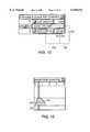
- FIG. 7is an illustration of a display screen when the ventilator control system is in the operational mode.
- FIG. 8is an illustration of a section of the display screening showing a minute volume wheel.
- FIG. 9is an illustration of a section of the display screening showing a control slider.
- FIG. 10is an illustration of a section of the display screening showing a numerical controller.
- FIG. 11is a flow chart of the data structure hierarchy employed by the ventilator control system.
- FIG. 12is an embodiment of a flow chart of an exhalation assist algorithm executed by an embodiment of the invention.
- FIG. 13is an illustration of a simulation mode display screen for the ventilator control system.
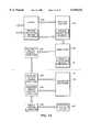
- FIG. 14is a functional block diagram of the simulator portion of the ventilator control system
- FIG. 15is an illustration of a section of the display screening showing a waveform shaper.
- FIG. 16is an illustration of a therapy programming screen for the ventilator control system.
- Ventilator Control Systemfeatures a ventilator control system for controlling a ventilator pneumatic system in a medical ventilator.
- the ventilator control systemprovides a clinician with complete control of a patient's airway flow and pressure throughout the respiratory cycle, and thereby enables the clinician to determine the optimal therapy for the patient.
- negative pressurecan be applied to the exhalation circuit of the patient's ventilator to reduce the resistance to airflow.
- PEEPpositive end-expiratory pressure
- FIG. 1is a block diagram of a ventilator including a ventilator control system 10 incorporating the features of the invention.
- the ventilator control system 10includes a display controller 12 and an embedded controller 14.
- the display controller 12provides an interface to the clinician 16, and the embedded controller 14 provides an interface with a ventilator 17 providing ventilation to a patient 20.
- the display controller 12 and the embedded controller 14each include memory (not shown) and are electrically coupled via a shared memory interface 15. Data from the display controller 12 and the embedded controller 14 are stored in a database 13.
- a sensor monitoring system 19, including an exhalation flowmeter 11 a circuit resistance sensor 9 and a pressure sensor 7 in communication with the airway 21,provide signals to a embedded controller 14 relating to airway pressure, flow and resistance. These measured values are stored in a database 13. These values are also compared with values preselected by a user by way of the embedded controller 14 to calculate the amount of negative pressure to be generated in the ventilator 17 in order to produce an airway pressure greater than zero and less than positive end-expiratory pressure.
- a pneumatic system 41regulates the flow of gas delivered from the source of pressurized gas 45 through a Venturi valve within the ventilator 17 to produce this negative pressure.
- One embodiment of such a pneumatic system 41is described in U.S. Pat. No.
- a pressure sensor 51measures the amount of negative pressure produced within the ventilator 17 and transmits these data to the embedded controller 14. These data are stored in the database 13 and displayed on the display 24 of the display controller 12.
- the clinician 16enters target values into the system 10 by way of the input device 26 of the display controller 12. Each of these target values is compared with a corresponding current value of ventilatory unit pressure, airway pressure, airway flow and airway resistance by the embedded controller 14. Upon determining that there is a difference between current pressure, flow and resistance values and those values entered by the clinician 16, the embedded controller 14 generates a signal to the pneumatic system 41 so that the pneumatic system 41 changes the amount of negative pressure produced by the ventilator 17.
- the ventilator 17is in pneumatic communication with a flexible tubing 21 capable of attachmnent to apatient 20.
- the clinician 16can also directly adjust the pneumatic system 41 by manipulating a plurality of controls on the input device 26 of the display controller 12.
- the clinician 16enters numerical data at the display controller 12 relating to the desired level of airway resistance in the flexible airway tubing 21 or relating to the desired amount of negative pressure in the pneumatic system 41. These entered values signal the pneumatic system 41 to change the amount of negative pressure on a per breath basis within the pneumatic system 41 until the pressure in the pneumatic system 41 or the resistance in the airway tubing 21 equals the value entered by the clinician 16.
- the pneumatic system 41controls gas flow and pressure in the patient's airway using a patient circuit.
- An electromechanical fresh gas flow control and measurement systemprovides a metered blend of oxygen and air via a heated, humidified gas delivery system.
- a high speed pneumatically driven, electronically controlled proportional valve and dual Venturi systemprovides bi-directional flow and pressure control as described in U.S. Pat. No. 5,664,563 incorporated herein by reference.
- Pressure 7 and flow 11 sensorsprovide feedback control of the desired breathing pattern and verify operation within safe limits.
- the pneumatic and electronic systems and patient circuitare described in extensive detail in commonly assigned patent application, Ser. No. 08/352,658, incorporated herein by reference.
- the safe performance of the ventilator 10is enhanced by the redundancy of the two independent display controller 22 and embedded controller 30 processors, which continually check each other's performance via the shared memory interface 15.
- the embedded controller 14communicates its status, and that of the patient, to the display controller 12.
- the embedded controller 14maintains a non-volatile record of the therapy control structure and continues to operate at the last known good settings if communication becomes lost.
- the two systems which comprise the ventilator control system 10give both audible and visual messages when an alarm condition exists, and maintain an alarm history.
- the systemsprovide alarms and mandatory patient support upon detection of apnea (i.e., the detected absence of breathing). During operation, both systems perform background tests to detect system faults.
- the ventilatorprovides a series of reduced operation modes to provide life support if system capability is compromised.
- FIG. 2is a block diagram of the display controller 12.
- the display controller 12includes a processor 22, a display 24 and an input device 26.
- the input device 26is a touchscreen used in conduction with the display 24.
- the processor 22collects input information from the clinician 16, validates the input, creates a therapy control structure from the input information and sends the resulting structure to the embedded controller 14.
- the therapy control structureis a hierarchical arrangement of similar data structures which includes one or more mode control structures, one or more breath control structures, one or more phase control structures and one or more cycle control structures. Data generated and collected by the processor 22 are stored in the database 13.
- the display 24maintains and displays the patient's history in a graphical format which highlights the patient's status.
- the display 24is a CRT. In another embodiment, the display 24 is a flat panel display. More specifically, the display 24 provides a visual indication of the current breath control parameters, alarm and fault conditions, and the current status of the patient's pulmonary system, including gas pressure, flow and volume. In one embodiment, the touchscreen 26 covers the surface of the CRT display 24 and provides a straightforward, highly flexible means to change control settings.
- the display controller 12is a powerful graphics workstation with hardware and software components.
- the clinicianinteracts with the display controller 12 via a color CRT monitor 24 and a touchscreen 26.
- the display 24is modified to run from an isolated power supply, and the touchscreen power supply and controller are built in to the monitor.
- the processor 22is included in a single board computer which also includes RAM, an integrated high speed graphics driver, and an integrated dual port memory.
- the display controller 12also includes a hard disk drive 23.
- the display controller 12provides interpretation and decision support information on the display 24, the ventilator 17 does not change any breath control parameters unless directed by the clinician 16. Nevertheless, the display controller 12 provides a flexible user interface with multiple interactive levels, from simple text menus of controls for inexperienced users, to complete visual feedback for clinicians who understand the patient models and can intervene more aggressively and effectively.
- the embedded controller 14includes a system board 28, a real time data processor 30, a ventilator processor 32 and an airway processor 31.
- the real time processor 30manages sensor data collection from the sensor monitoring system 19, processes measured data, performs alarm/fault detection and provides control data to the ventilator 17.
- the embedded controller 14further receives data input by the clinician 16 and accesses with the database 13.
- This data processor 30calculates the amount of negative pressure that must be generated by the pneumatic system 41 to change the airway resistance to exhalation. This calculation is made by comparing the data relating to airway pressure, flow and resistance to preselected values and then calculating the change in ventilatory unit negative pressure required to affect the desired change in airway resistance.
- FIG. 4a block diagram of the ventilator 17 in communication with the flexible airway 21 that is the conduit for inhalation from the patient 20 is depicted.
- the pneumatic system 41regulates the amount of negative pressure produced within a rigid chamber 43 by adjusting the flow of gas from a source of pressurized gas 45 through a Venturi valve 47.
- Within the rigid chamber 43is a flexible canister 49. Negative pressure produced within the rigid chamber 43 is transmitted to the flexible canister 49 and thus to the patient airway 21 which is in pneumatic communication with the flexible canister 49. In this way, negative pressure is applied to the patient airway 21 to assist the patient's exhalation through the canister 49 into the medical ventilator 17. Pressure within the flexible canister 49 is measured by a pressure sensor 51. These data are transmitted to the embedded controller 14.
- FIG. 5a detailed functional block diagram of the ventilator control system 10 is depicted.
- the clinician 16manipulates a control setting slider 34 to change or set one or more breath parameters.
- a change alert panel 36 on the display 24informs the clinician 16 of the process, from input to implementation, to assure him that his input information is being processed properly.
- a change to one or more breath parameterswill lead to changes in one or more data structures of the therapy control structure hierarchy.
- FIG. 5provides an example of a breath parameter change which results in a change at the level of the breath control structure.
- the validation processincludes the processor 22 validating 38 the clinician's inputs and creating 40 a breath control structure which is stored in memory.
- the display controller 12transmits the breath control structure to the embedded controller 14 and informs the clinician 16 of successful transmission via the change alert panel 36.
- the embedded controller 14initially stores 44 the breath control structure in local memory.
- the embedded controller 14re-validates 46 the settings within the breath control structure.
- the embedded controller 14implements 48 the validated breath control structure 48 using a breath control algorithm 50 and provides signals to the pneumatic system 41 for simultaneously changing one or more control settings at the appropriate time. This process enables the user to change or implement a new therapy so that the therapy delivered to the patient is essentially uninterrupted, and the new therapy is synchronized with the next inspiration. If, however, any step in the process is not completed, the clinician is alerted via the panel 36 to the cause of the error and the process is terminated.
- the ventilator control system 10provides two independent feedback paths to assure the clinician 16 that his setting change has been properly implemented.
- the embedded controller 14calculates a series of breath monitoring values and sends them to the display controller 12, where the values are displayed 60 contiguous to the desired setting controls.
- the breath monitoring valuescan be, for example, set breath rate, measured breath rate, set tidal volume, measured inhaled volume, and measured exhaled volume.
- the display controller 12also displays 60 a series of measurements (e.g., peak airway pressure, peak airway flow, and PEEP) from the waveform data both numerically and graphically.
- the display controller 12displays 54 the continuous waveforms on the display 24.
- the waveformsare derived 56 from raw data from the sensors 19, returned from the embedded controller 14 and passed directly to the display 24.
- the ventilator control system 10can be configured to provide an assisted phase of a breath to the patient 20.
- the accumulated volume of gas inhaled by the patient as a result of his spontaneous respiratory muscle activitycan be monitored.
- the sensor monitoring system 19measures the flow of gas inhaled by the patient 20 at the beginning of the inspiration phase of the breath and integrates the flow to provide the measured volume.
- the embedded controller 14compares the measured volume to a trigger volume set by the clinician 16, and adjusts the plurality of controls within the pneumatic system 41 when the measured accumulated volume exceeds the trigger volume to provide an assisted phase of a breath.
- the embedded controller 14also may adjust the trigger volume dynamically according to measured patient flow and pressure signals indicating the phase of the respiratory cycle.
- the embedded controller 14may increase the trigger volume set by the clinician 16 during periods of the breath where increases in the pressure at the airway of the patient 20 may be induced by changes in the pneumatic system 41, and not by spontaneous efforts of the patient.
- Another feature of the ventilator control systemis its ability to distinguish between active inspiratory effort and passive reverse airflow due to the elastic rebound of the chest wall and lungs.
- the present systemis configured such that if the patient's spontaneous inspiratory efforts are being assisted, passive reverse airflow can not erroneously trigger an assisted breath.
- pressure and flow data provided by the sensor monitoring system 19are analyzed by the imbedded controller 14 to discriminate between passive airflow and active initiation of inspiration. Specifically, referring to FIG. 6 and 6a, the clinician sets the trigger volume needed to initiate a breath. The system 10 then determines the baseline pressure and flow for the patient.
- the system 10monitors both the patient airway flow and the patient airway pressure. Referring to FIG. 6, if the gas flow is seen to flow into the patient, and the pressure slope is positive, the flow into the patient is considered to be a result of overshoot and no inhalation is triggered (FIG. 6a). If the pressure decreases and the gas flow is into the patient (Step 300), then the total amount of gas inhaled by the patient is measured, and compared to the trigger volume (Step 310).
- Step 320, 330If the total amount of gas inhaled is greater than the trigger volume and this value has been reached in less than 200 msec, a breath is initiated. If the trigger volume has not been reached and it is taking more than 200 msec, the volume of inhaled gas is continued to be measured until the trigger volume has been reached (Steps 320, 330).
- Another feature of the ventilator control systemis its ability to compensate for gas flow resistance into and out of the lungs of the patient 20.
- the clinician 16can set a resistance parameter of the patient's respiratory system to a selected value.
- the display controller 12may calculate a value for the gas flow resistance from gas flow and pressure measurements provided by the sensor monitoring system 19. The gas flow resistance is described by the equation:
- the selected or calculated resistance valueis provided to the embedded controller 14 by the display controller 12.
- the embedded controller 14adjusts one or more controls of the pneumatic system 41 to compensate for the resistance to flow.
- the compensation for resistance to flowmay be selected to occur during any one or more of the inspiration, exhalation or post-breath phases of a breath. Further, the controls may be adjusted to compensate for different selected or calculated resistance during different phases of a breath.
- the display controller 12is an intelligent assistant for the clinician 16.
- the display controller 12quickly informs the clinician 16 of the effects of intervention, provides fast, graphical feedback, and presents information in a manner that requires minimal training to understand.
- the display controller 12uses software-generated waveforms and software-generated icons for control and alarms settings.
- the bottom row of touch sensitive on/off buttons 66includes: a Power button that controls the ventilator control system; a Freeze button to pause the display; a Modes button to display various modes; a History button to play back a database of historical patient protocols; a 100% O 2 button to flush the ventilator with oxygen; Help and Save buttons; and an Others button to display other capabilities.
- the left side of the screenincludes a list of the publically available ventilator control settings.
- the top areadisplays the current mode of ventilation 67 (e.g., Backup).
- each row in the listhas three columns.
- the left columnis the current set value. If a row in the left column is inactive, it displays an OFF indication. Important current set values are highlighted.
- the middle columnis a touch sensitive display showing the abbreviated title of the setting.
- the right columnis the actual value of the setting as measured during the previous breath. If the actual value exceeds an alarm limit, the exceeded value turns red and a large alarm message is displayed on the screen.
- a control slider(not shown) appears on the right side of the screen. The control slider enables the clinician to change various parameters (e.g., alarm levels, control settings) and is described in detail below.
- the middle area of the display screenis divided into top and bottom regions (70, 72).
- the bottom region 72can include a variety of virtual instruments including: additional user-defined waveforms, trendlines, an events log, measured minute averages and other options.
- the top region 70includes real time airway flow and pressure waveforms (74, 76), which are displayed over different shades of gray to indicated the breath phase.
- the airway flow waveform 74illustrates flow into the patient, or inspiration (positive flow), and flow out of the patient, or exhalation (negative flow).
- the pressure waveform 76illustrates that the patient's airway rises above ambient for inspiration and falls during exhalation.
- the waveformsare tracked by a cursor that can be programmed to follow a peak, average, plateau or manually set position.
- the waveformsare displayed in fixed axis, moving erase bar format.
- the time axis resolutionis user adjustable and displays time in seconds. Overwriting of the display starts at the beginning of an inspiration, so that the first displayed breath starts at a fixed point on the screen.
- the vertical axesare scaled to keep the displayed waveforms and settings in clear view.
- the right side 77 of the display screennormally includes a flow-volume loop 78, a pressure-volume loop 80 and a minute volume wheel 82.
- a control slider and other optional panelscan overlay this side when a user so desires.
- the flow-volume loop 78is updated each breath to show the timing of delivered airflow.
- the vertical axis of the loopshares a common range and alignment with the airway flow waveform 74.
- the pressure volume loopis updated each breath to show the condition of the lungs.
- the vertical axis of the loopshares a common range and alignment with the pressure waveform 76. Calculated resistance and compliance are also displayed.
- the minute volume wheel 82provides a comprehensive summary of the patient's breathing for the last minute.
- the minute volume wheeldisplays a wealth of historical breath information (e.g., minute volume, inspiration phase, exhalation phase, inspiration/exhalation ratio, breathing rate, spontaneous minute volume, inhale tidal volume, exhale tidal volume, leakage) on a single integrated graphic circle so that the clinician can readily evaluate ventilation during the last minute.
- breath informatione.g., minute volume, inspiration phase, exhalation phase, inspiration/exhalation ratio, breathing rate, spontaneous minute volume, inhale tidal volume, exhale tidal volume, leakage
- a minute volume wheel 84represents one minute of ventilation as a circle with an area corresponding to measured minute volume.
- the measured minute volumeis represented numerically, as the center number, and graphically, as a circle 86 drawn over a background circle 88 that has an area corresponding to the target minute volume.
- the two circlesare blended in color and appear as one circle.
- the background circlebleeds through and is visible.
- an uncovered portion of the background circleis visible.
- One minute of ventilationis drawn as a circle 90, one wedge at a time, and is redrawn once a minute. Like the face of a watch, each degree of the circle 90 corresponds to one sixth of a second.
- Each inspirationis drawn as a wedge 92 with an area corresponding to delivered volume. This wedge is drawn over an inspiration spoke 94 that extends to maximum minute volume.
- Each exhalationis drawn as a wedge 96 with an area corresponding to exhaled volume. This wedge is drawn over an exhalation spoke 98 that extends to maximum minute volume.
- the spokesindicate breathing regularity and inhale to exhale (I:E) time ratio, and the wedges indicate tidal volumes. Difference between the radius of inspiration and exhalation wedges indicates the I:E ratios.
- the I:E ratio and breathing rateare also represented numerically (100, 102).
- the pairs of inspiration and exhalation wedgesare coded by color to indicate spontaneous breaths, those triggered and partially controlled by the patient, and mandatory breaths, those triggered and controlled by the ventilator.
- the ratio of the colored areasindicates the ratio of spontaneous to mandatory breathing during the minute just past.
- the display controllerprovides a method for clinician control of the displayed waveforms.
- Each waveform (74, 76)is continuously measured and displayed on a background that changes color to indicate the phase of a breath.
- the rectangular area 200 for any phase of the waveform (74, 76)is used as a target for the touchscreen.
- the display controllerdisplays the associated ventilator controls for available for adjustment by the clinician.
- the display controllerprovides cursors 201 which are actually floating windows. More specifically, windows of one or two pixels width float over the waveforms (74, 76), thereby creating cursors 201. Since the cursors are independent of the background waveform graphics, numerous advantages result including drawing optimization, dynamic repositioning based on changing waveform values, positioning based on user interface gestures.
- the background of the waveform(74, 76) includes color shading to indicate breath phase, title, units and scale information. Redrawing these graphics as new waveform samples are displayed generally requires substantial computer time, and the display controller performs this function efficiently notwithstanding the complexity of the background image.
- background imagesare created once. A narrow rectangular region 202 is removed from these images and pasted in front of the moving waveform to clear out the previous waveform and refresh the background prior to the new waveform. The width of the rectangular area 202 is kept sufficiently small so that the refresh is smooth in appearance.
- the x-axis coordinate of the current waveform positionis used to control the x-axis position from which to remove a strip of background image. Multiple color coded background images can be maintained (e.g., three gray shades for the breath phases) and images removed from the desired one depending on the state of the waveform.
- the clinician 16can display the control slide 104 for the control setting in a fixed location at the right of the screen, as shown in FIG. 9.
- a scroll bar title 106located near the top of the slider 106, indicates the name of the control setting.
- the full vertical range 108indicates the allowed set limits.
- the center sliderindicates the current position 110 and the range 112 of the control setting.
- the upper and lower sliders (114, 116)indicate the current alarm limit settings. The position 110 of the current setting within the allowable range 112 and within the alarm limits (114, 116) is readily apparent to the clinician.
- the cliniciancan move any of the sliders to change the set values in steps of approximately 1% of the allowable range, or with the "Exact” button selected, approximately ten times more precision (i.e., about 0.1% of the allowable range).
- the cliniciandepresses the Accept Changes button to change the parameter.
- Alarm settingsare matched with control settings in the appropriate control sliders. Some control settings have two associated alarms, others have only one associated alarm or do not have any associated alarms. For example, both high and low inspiratory pressure alarms are provided on the Airway Pressure control slider. If an alarm limit is exceeded during operation, the alarm is displayed in an alarm window, and an audio alarm turns on. Alarms are non-latching, i.e., the alarm indication turns off when the detected level no longer violates the set limit. Available control settings and ranges, alarm settings and ranges, and measured parameters are listed in the following table:
- the display screen 24is covered by a resistive touchscreen.
- Known touchscreen interfacesrequire that the user touch a graphic object on the screen, but this action generally obscures the object.
- the touchscreen interface of the present inventiondefines an area whose shape, size and position is dynamically computed based on the characteristics of the associated graphic object. The interface interprets touching by the user as a manipulation of the associated graphic object. More specifically, a dragging motion moves the associated object, or change its value or other attributes.
- the display controllerincludes software for manipulating the characteristics of the breath parameter Airway Pressure 106 displayed in the control slider 104 on the touch-sensitive display 24.
- the display controller 12dynamically defines a touch zone on the touch-sensitive display. More specifically, touch zones are defined for each slider (i.e., high alarm, low alarm, position and allowable range) within the control slider. Each touch zone is slightly larger than the displayed slider. By way of example only, the touch zone for high alarm may extend into regions 118 to either side of the color coded high alarm region 114.
- the display controller 12receives a touch signal when the clinician 16 touches any location within the touch zone and changes the range of the high alarm slider breath parameter in response to the touch signal. In other words, the display controller 12 increases the high alarm limit in response to the clinician 16 touching a location within the region 118 and dragging his finger in a upward path. Because his finger does not obscure the high alarm limit, the clinician can actually see the limit being change as it happens.
- the display controller 12includes software for providing precise numerical control without the requirement of a keyboard.
- the display controller 12displays a window 120 that looks like a numeric text field, but has a background color to distinguish the left region 122 from the right region 124, relative to the decimal point.
- a larger touch sensitive area 126, 128respectively is associated with each of the numeric regions.
- the embedded controller electronics 14is based around microprocessors 31, 32.
- the microprocessor 32is in electrical communication with the ventilatory unit 17 and the microprocessor 31 is in electrical communication with the sensor monitoring system 19.
- the embedded controllerrelies on industry standard bus based modules to perform certain functions and custom printed circuit boards to perform other functions.
- the modules, the printed circuit boards, the ventilatory unit pressure processors 32 and the airway processor 31are mounted on or connected to on a main printed circuit board 28.
- a real time operating systemis the foundation of the embedded controller software, which runs the algorithms required for measurement and control.
- a power systemconverts line power and provides battery backup for a average of one hour.
- the embedded controller 14has microprocessor and associated input/output hardware to provide for closed loop control of pneumatic system 41 and the acquisition of patient data.
- the embedded controller 14communicates the status of the patient and its own status to the display controller 12.
- the embedded controller 14responds to commands and setting changes received from the display controller 12, and maintains a non-volatile record of instrument settings to maintain operation in the absence of both communication from the display controller and line power.
- the embedded controller 14performs real time data acquisition of twenty three different analog input signals including:
- the embedded controller 14also monitors six switches:
- the embedded controllercontrols nine digital outputs:
- the embedded controller 14controls four duty cycle modulated digital outputs:
- the embedded controller 14communicates with the display controller 12 via a shared memory interface 15 at a data transmission rate exceeding 100 K bytes per second.
- Data StructuresThis section describes the architecture for software utilized in the embedded controller and shared with the display controller.
- the architecture of the softwareis built around the concepts of therapy controls, mode controls, breath controls, phase controls and cycle controls.
- a data structure driven state machinedetermines the control parameters for each therapy control, mode control, breath control, phase control, cycle control and exhalation assist.
- the figuresillustrate the data structure hierarchy for the ventilator control system.
- a cliniciancan change ventilation control settings to create a new therapy comprising a therapy control structure 140.
- the settingsare validated by the display controller 12, placed into a new therapy control structure and sent to the embedded controller 14.
- the embedded controller 14validates the settings again and checks the integrity of the new structure before the new therapy control is accepted.
- the clinician 16may simulate the behavior of the new therapy control using a simulator and may allow others to utilize the therapy control by adding it to the database 13. In any case, the clinician 16 sends the new therapy control structure to the memory for use by the embedded controller 14 in controlling the pneumatic system 41.
- a therapy control structure (or a mode control) 140is defined as a collection of mode control structures 142 and mode switching rules 144.
- a mode control structure (or a breath control)is defined as a collection of breath control structures 146 and breath switching rules 148.
- a breath control structure 146(or a phase control) is defined as a collection of phase control structures 150 and phase switching rules 152.
- a phase control structure 150(or a cycle control) is defined as a collection of ventilator control settings 154 and an array of waveform samples 156. Phase definitions and requirements for transitions between phases are tied directly to measurable system performance, and correlate closely to published descriptions of the desired behavior of mechanical ventilators.
- the therapy control structure 140is a nested hierarchy of increasingly complex control structures.
- a cyclee.g., a 4 msec time slice
- phase controlwhich occurs within breath control, which occurs within mode control, which occurs within therapy control, which is the clinically specified therapy that drives the ventilator pneumatic system 41.
- mode controlwhich occurs within therapy control, which is the clinically specified therapy that drives the ventilator pneumatic system 41.
- a new therapy control structure 140may cause a branch to the first cycle of the first phase of the first breath of the first mode of ventilation within the new therapy control structure, or the new therapy control structure may be delayed a few cycles until better patient synchrony can be achieved.
- mode control structures 142there is a collection of mode control structures 142 and a collection of rules specifying how and when to switch from one mode of ventilation to another one.
- a therapymay define several different modes of ventilation and mode switching rules 144 for the transition from one mode of ventilation to another.
- the mode switching rules 144may cause a branch to the first cycle of the first phase of the first breath of another mode of ventilation within the therapy control structure 140.
- a modewhich is within a therapy, there is a collection of breath control structures 146 and a collection of breath switching rules 148 specifying how and when to switch from one breath type to another breath type within the same mode.
- breath control structures 146and a collection of breath switching rules 148 specifying how and when to switch from one breath type to another breath type within the same mode.
- a mode of ventilationmay have several different types of breaths defined, and rules specified for how to go from one breath type to another.
- the breath switching rules 148may cause a branch to the first cycle of the first phase of another type of breath within the mode.
- a breathwithin a mode, within a therapy there is a collection of phase control structures 150 and a collection of phase switching rules 152 specifying how and when to switch from one breath phase to another phase within the same breath.
- a breath typemay have several different phases defined, and rules specified for how to go from one breath phase to another. For example, breathing generally proceeds from an inspiration phase to a pause phase to an exhalation assist phase to a PEEP phase, but these phases may be further subdivided for a finer granularity of control.
- the phase switching rules 152may cause a branch to the first cycle of the next phase within the breath type.
- a ventilator control setting structure 154This structure contains an array of samples that comprise a specified waveform shape.
- the control logicis driven by the waveform sample specific for the cycle, and by a collection of ventilator control settings 154 specific for the phase.
- the cycle timeis in milliseconds, and is currently set to four milliseconds.
- the hierarchy of rulesis tested and the state is set for the next cycle, which is by default the next cycle within the current phase, current breath type, current mode of ventilation and current therapy.
- higher level rulesmay cause a change in breath phase, breath type, mode of ventilation, or an entirely new therapy may be specified by the clinician and take control at the next cycle.
- Each ventilator control setting structure 158contains necessary and sufficient information to control one parameter of ventilation, including whether there is a high alarm level, whether the high alarm is active, whether there is a control level, whether the control is active, whether there is a low alarm level, whether the low alarm is active, whether there is a range level, whether the range is active, and a range target control structure to define how and why the parameter is to be adjusted automatically within the specified range.
- Each phase control structurehas its own collection of ventilator control settings, although in practice, phases within a breath generally share the same collection.
- the data structure-driven architecture described aboveenhances safety and reduces the likelihood of hazardous conditions by permitting non-programmers to review and understand the function of the ventilator control system.
- breath control structuresare predefined in the embedded controller. These breath control structures are used when hazards are detected, such as apnea or patient circuit disconnect. They are also used to support the patient if the communication link between the display controller 12 and embedded controller 14 is lost. Also, the embedded controller 14 checks the integrity of every therapy control structure sent by the display controller 12. If a requested change is invalid, the embedded controller 14 continues operation with the last known valid therapy control structure. If no valid therapy control structure has been received, the embedded controller 14 uses the predefined breath control structures to continue patient support.
- FIG. 12is a flowchart of an embodiment of an algorithm executed by the exhalation assist device embodied in FIG. 1.
- the algorithmbegins with the clinician 16 entering the desired values relating to airway resistance or negative pressure in the ventilatory unit (Step 1). These values are then compared with data relating to airway resistance or negative pressure in the ventilatory unit that have been measured or calculated by the data processing unit (Step 2). It is then determined whether these sets of data are equal to each other or are within a predetermined range of each other (Step 3). If these values are equal or within a predetermined range, airway flow is then measured (Step 5). If these values are not equal or within a predetermined range, the applied negative pressure is adjusted (Step 4), and then the airway flow is measured (Step 5).
- Step 6After airway flow is measured, it is determined whether the measured airway flow is a positive or a negative number (Step 6). If airway flow is positive, indicating that inspiration is occurring, a new measurement of airway flow is obtained (Step 5). If airway flow is negative, indicating that exhalation is occurring, airway pressure is measured (Step 7). It is then determined whether airway pressure is greater than zero and less than PEEP (Step 8). If airway pressure is greater than zero and less than PEEP, airway resistance is calculated and pressure in the ventilatory unit is measured (Step 9). After these measurements and calculations are made, the cycle recommences (Step 2). If airway pressure is not greater than zero and less than PEEP, it is determined whether the alarm has been overridden (Step 10).
- Step 5If the alarm has been overridden, airway flow is measured on the next breath (Step 5). If the alarm has not been overridden, the alarm is triggered (Step 11). If the alarm is triggered, the cycle must be restarted with the input of desired values (Step 1).
- a simulator 212is provided for predicting the status of the pulmonary system of a patient and a database 13 for storing actual or simulated historical patient protocols.
- the simulator 212is electrically connected to the display and embedded controllers 12, 14 respectively.
- the simulator 212uses a set of breath parameters provided by the clinician 16 via the input device 26 to predict the status of the patient's pulmonary system.
- the simulator 212simulates the adjustment to the ventilator pneumatic system 41 in response to the set of breath parameters and the response of the patient's pulmonary system to the adjusted pneumatic system 41.
- the predicted status and the set of breath parametersare displayed on the display screen 24 (FIG. 13).
- An advantage of the simulator 212is that the clinician 16 can experiment with new or old settings, while the actual settings remain unchanged and the patient is unaffected.
- the ventilator control system 10predicts the effects of the change and displays the predicted result on the display 24.
- the simulator 212uses a standard two parameter model of a respiratory system and the current calculated values of the patient's resistance and compliance to predict the effect. The model assumes no contribution from the patient's respiratory muscles (i.e., a passive inspiration and exhalation cycle).
- the model usedis:
- a change in patient intervention in current ventilatorstypically requires multiple setting changes. Implementing such setting changes is greatly complicated by the series of indeterminate control states as one setting is changed at a time.
- the clinician 16can change multiple settings until the predicted waveforms are satisfactory and then activate all the changes simultaneously. If the clinician 16 is dissatisfied, he can quickly and conveniently return the control settings to their previous values without adversely affecting the patient.
- the clinician 16can also use the simulator 212 to select a mode of ventilation or sequence by modes, by choosing a programmed comprehensive therapy control structure. Those breath parameters, which are essential to the definition of the mode, are highlighted with a color-coded background. Other controls are listed as active or inactive. The explicit list of active controls clearly delineates the exact function of the mode and alleviates confusion caused by inconsistent or incomplete definitions. Moreover, the simulator 212 can precisely replicate the behavior of modes on preexisting ventilators. The clinician 16 can make adjustments to the list of controls to accurately simulate the ventilator that a hospital's staff has been trained to use. The list of controls together with the simulated behavior can help teach the effects of various modes on patients, rather than the ventilator-specific mode definition.
- the simulator 212predicts the shape of the breaths using the two parameter model, and displays the simulation on the display 24, many other physiological models and predictions may be possible. Specifically, the simulator 212 may predict the effect of positive end expiratory pressure on lung volume and functional residual capacity; it may predict the effect of minute volume on blood oxygen and carbon dioxide levels; it may predict the effect of mean airway pressure on pulmonary blood flow; and it may provide other similar models.
- the database 13assists the clinician 16 in managing the intervention and in tracking patient status.
- the database 13makes large amounts of stored patient data available at several levels of detail and encourages comparison of different patient data.
- the clinician 16can compare stored historical patient data with current settings to learn whether the current intervention has been effective and whether the patient is progressing.
- the database 13is electrically coupled to the display controller processor 22 and stores a plurality of patient protocols.
- Each patient protocolincludes at least a set of breath parameters and patient data.
- the breath parametermay be organized as one or more therapy control structures.
- the clinician 16selects a patient protocol by depressing a touch zone on the display 24.
- the processor 22copies the selected patient protocol into memory.
- the processor 22instructs the embedded controller 14 to simultaneously adjust the controls of the pneumatic system 18 using the selected patient protocol.
- the simulator 212simulates the adjustment to the ventilator pneumatic system 41 and the resulting response of the patient's pulmonary system.
- the processor 22stores patient protocols as epochs, which are complete and pattern discrimination to determine when to store epochs of interest. In this way, the clinician 16 does not have to decide a priori what may be important, what to "trend", or how to process the data. Because all the data is stored, it can be post processed to reveal any aspect of the patient's previous condition.
- the saved epochsare organized in the database. Access to the epochs can be by time, by event, or by area of interest. The ability to overlay data from previous epochs informs the clinician as to whether the patient is progressing, or whether the intervention is working as expected.
- FIG. 14is a detailed functional block diagram of the simulator feature of the ventilator control system 210.
- the clinicianmanipulates a control setting slider 216 to change or set a ventilator control setting.
- the clinician's inputare stored in a memory 218.
- the simulator 220receives the inputs and creates a phase control structure, a breath control structure, a mode control structure, or a therapy control structure for use in its simulation. If, for example, the clinician 16 decides to use the breath control structure 222 to change the patient's therapy, the selected breath control structure (which is embedded within a mode control structure within a therapy control structure) is transmitted to the embedded controller (at 224) via the shared memory interface.
- the embedded controllervalidates the settings within the breath control structure 226.
- the processorimplements the validated therapy control structure 228, which includes the breath control structure, in a breath control algorithm 230 and provides signals 232 to the pneumatic system for simultaneously changing one or more control settings.
- Waveform Shaper--The waveform shaper shown in FIG. 15is a graphical tool which enables a clinician to shape one or more phases of a breath. Characteristics such as the rise time and shape 130, the plateau length and shape 132, the fall time and shape 134 can be drawn to any desired characteristics by the clinician. In one embodiment, the phases can be shaped by touching the various active areas dynamically created on the touchscreen display displaying the waveform shaper and drawing the finger in the desired direction. In another embodiment, control buttons may be selected to add characteristics to the waveform, specifically sinusoidal or pulse-like variations about an average level during a phase.
- the waveform shaperis displayed by the display controller 12, wherein its output is used to fill the array of waveform samples 156 in the cycle control structure of the therapy control structure 140.
- the pneumatic system 41 in communication with the embedded controller 14can in this way be directed to follow any arbitrary waveform "drawn" by the clinician for one or more phases of a breath.
- the patient data waveformsare driven by a data stream protocol.
- the data streamcan be generated by sensors, which is the usual manner in which the ventilator operates, by the simulator 212 which uses the breath parameters and measured patient parameters to generate simulated sensor data, or by the stored sensor data in epochs to show historical patient behavior.
- the ability to use the same interface to display real data, simulated data and epoch datais an important feature of the ventilator control system.
- patient data waveforms 74,76 presented on display screen 64 of the display controller 12combine setting control, data and alarm displays in a single region.
- the association of numbers and graphic icons with the data waveformsprovide context to illuminate the meaning of the numbers and icons without unnecessary data or unit labels.
- a light line 201is apparent as peak flow or pressure; a heavy bar 204 is apparent as the peak pressure set level; a light bar 203 is apparent as a high pressure alarm setting; an active rectangular region 200 on the pressure waveform is apparent for setting the exhalation pressure level. Differences between desired and actual settings, and alarm margins are readily apparent.
- the simplicity of these representationscan be contrasted to a typical list of controls, calculated data, and alarms, where each item on the list is in LABEL:VALUE:UNITS format and the integration and comparisons must be performed in the head of the clinician.
- FIG. 16is an illustration of a therapy programming screen 205 provided by the display controller 12.
- the clinician 16can create or modify one or many breath parameters to prescribe a new type of therapy for the patient. Changes made are reflected at one or more data structure levels in the therapy control structure created in the display controller 12. After validation, the new therapy control structure can be sent to the embedded controller 14 for immediate implementation, or saved to a list of therapy prescriptions for later use.
- a therapycan thus be built from the simple to the complex. Breath parameters are selected and changed to modify and combine cycles to define a phase; to modify and combine phases to define a breath; to modify and combine breaths to define a mode; and to modify and combine modes to define a therapy program.
- the selectionsare reflected in the hierarchy of structures in the therapy control structure, as previously described.
- the collection of settingsare given a title by the clinician, in common use loosely defined as a mode of ventilation.
- the creation processwith its explicit connection of breath parameters to a mode definition, helps clarify the way the therapy will affect the patient. In contrast, modes preset by the manufacturer often have implicit, obscure and contradictory affects on the patient.
- the therapy programming screen 205enables selection and changing of related breath parameters.
- the therapy prescription to be alteredis selected from a list; a new therapy prescription can be created by selecting a similar prescription from the list, giving it a new title, and altering it as needed.
- a mode within the selected therapy prescriptionis selected; a breath within the selected mode is selected; a breath parameter control setting within the selected breath is selected; a sequence which identifies a specific, hierarchically nested breath parameter.
- Features of the breath parameterare toggled on or off, or chosen from lists which are brought forth when there are more than two choices. Every breath parameter, within each breath, within each mode, must be programmed to complete the therapy prescription.
- a control definition section 207is displayed adjacent to the control slider previously described.
- the control definition section 207includes a title 209 of the therapy prescription.
- the title in this exampleincludes two modes, and the mode (A/C pc) to which the selected breath parameter is tied is highlighted.
- the control setting for the breath parametermay have a range feature enabled 211, which, if enabled, will bring forth a panel of selected targets appropriate for the range, and which, if enabled, means that the ventilator control system will seek to accomplish a range target goal 213 by varying the control setting within the range specified in the control slider.
- the control settingmay be required to be on 215, meaning that it cannot be turned off by the clinician when operating within this breath type within this mode. It may be required to be off 217, meaning that it cannot be turned on by the clinician when operating within this breath type within this mode.
- the therapy programming screenallows the control setting to be shared by one or more other breath types 219 within the mode, or within the paired modes, such that any adjustments to the control setting will affect all such breaths. It allows control settings to be highlighted 221 as having primary importance to clinicians making adjustments to therapy. It allows multiple breath types to be defined, and provides a selection of rules that will be tested to determine which breath type to use within the mode.
- the embodimentallows the clinician to select from a number of triggers which determine the transition between modes of ventilation 223, when a multi-mode feature is enabled 225.
- the triggers for transitionmay be different depending on the direction of the transition.
- the trigger for the transition from variable pressure support (VPS) to assist control (A/C pc)is minute volume (MV)
- MVminute volume
- Sensei.e. patient effort
- therapy prescriptionswhich encompass many modes, with multiple triggers for the transitions between modes.
- other prescriptionsinclude sequences of modes which automatically change the treatment of a patient as his condition changes, and allow the clinician to readily control the sequence.
- Other prescriptionspermit time limited modes, which turn on for a period and then revert to the mode, or combinations of modes, in effect prior to their turn on.
- the therapy programming screenenables the clinician to tune the therapy to the specific and ever changing needs of the patient, with much more power and flexibility than selecting from a set of simple ventilator modes preset by the manufacturer.
Landscapes
- Health & Medical Sciences (AREA)
- Engineering & Computer Science (AREA)
- Biomedical Technology (AREA)
- Public Health (AREA)
- General Health & Medical Sciences (AREA)
- Life Sciences & Earth Sciences (AREA)
- Veterinary Medicine (AREA)
- Hematology (AREA)
- Anesthesiology (AREA)
- Animal Behavior & Ethology (AREA)
- Pulmonology (AREA)
- Emergency Medicine (AREA)
- Heart & Thoracic Surgery (AREA)
- Business, Economics & Management (AREA)
- General Business, Economics & Management (AREA)
- Epidemiology (AREA)
- Medical Informatics (AREA)
- Primary Health Care (AREA)
- Measurement Of The Respiration, Hearing Ability, Form, And Blood Characteristics Of Living Organisms (AREA)
Abstract
Description
Gas Flow Resistance=(Inspiration Peak Pressure-End Inspiration Plateau Pressure)/(Inspiration Flow at Peak).
______________________________________ Control Settings Tidal Volume (Compliance Compensated) 50 to 2000 mL Breathing Rate 2 to 150 bpm Peak Inspiratory Flow (BTPS Compensated) 10 to 120 L/min Oxygen Percentage 21 to 100% Peak Inspiratory Pressure 2 to 120 cmH.sub.2 O Exhalation Assist 0 to 30 cmH.sub.2 O/ L/sec PEEP 0 to 20 cmH.sub.2 O Inspiratory Time 0.2 to 4 sec Inspiratory Pause Time 0 to 1 sec Sensitivity (Patient Effort Trigger) 0 to 250 mL Flow Drop-Off Percentage (Percent of Peak) 5% to 80% Humidifier Temperature 30 to 60° C. Airway Temperature 15 to 40° C. Waveform Shape (clinician modifiable) custom, square decelerating modified fine Monitored and Displayed Parameters Exhaled Tidal Volume (Compliance Compensated) 50 to 2500 mL Measured Breathing Rate 2 to 150 bpm Peak Inspiratory Flow (BTPS Compensated) 10 to 120 L/min Oxygen Percentage 21 to 100% Peak Inspiratory Pressure 0 to 120 cmH.sub.2 O PEEP 0 to 20 cmH.sub.2 O Mean Airway Pressure 0 to 120 cmH.sub.2 O Inspiratory Time 0.1 to 4 sec Inspiratory: Expiratory Ratio 0.1 to 10.0 Minute Ventilation - Controlled 0 to 99 L/min Minute Ventilation - Spontaneous 0 to 99 L/min Airway Temperature 15 to 40° C. Lung Compliance 10 to 150 mL/ cmH.sub.2 O Airway Resistance 1 to 60 cmH.sub.2 O/L/s Leak 0 to 20 L/min Airway Flow Waveform -120 to ±120 L/min Airway Pressure Waveform -20 to +60 cmH.sub.2 O Flow-Volume Graph, Pressure Volume Graph see text Fresh Gas Flow Bar Graph see text Minute Volume Wheel see text Alarms and Indicators High/Low Exhaled Tidal Volume Alarm 50 to 2000 mL High/Low Respiratory Rate Alarm 2 to 150 bpm Low Oxygen Fresh Gas Flow Automatic, % O.sub.2 dependent Low Air Fresh Gas Flow Automatic, % O.sub.2 dependent Low Oxygen Supply Pressure Alarm 25 psig High/Low Airway Pressure Alarm 2 to 120 cmH.sub.2 O High/Low Inspiratory Time Alarm 0.2 to 4 High/Low Inspiratory: Expiratory Ratio Alarm 0.1 to 4.0 High/Low Minute Volume Alarm 1 to 40 L/min Airway Leak Alarm 1 to 20 L/min Patient Disconnect Alarm Automatic Apnea Alarm/Backup Ventilation 30 Internal Battery Notification Alarm Battery in Use % Remaining Pneumatic System Fault Alarm Automatic Alarms Silence 120 High/Low Oxygen Alarm 18-100% O.sub.2 ______________________________________
Airway Pressure=(Delivered Volume/Lung Compliance)+(Airway Flow×Airway Resistance).
Claims (10)
Priority Applications (8)
| Application Number | Priority Date | Filing Date | Title |
|---|---|---|---|
| US09/045,461US6158432A (en) | 1995-12-08 | 1998-03-20 | Ventilator control system and method |
| PCT/US1999/006056WO1999047200A1 (en) | 1998-03-20 | 1999-03-19 | Ventilator control system and method |
| US09/660,820US6584973B1 (en) | 1995-12-08 | 2000-09-13 | Ventilator control system and method |
| US09/767,173US6463930B2 (en) | 1995-12-08 | 2001-01-22 | System for automatically weaning a patient from a ventilator, and method thereof |
| US09/931,572US20020026941A1 (en) | 1995-12-08 | 2001-08-14 | Ventilator control system and method |
| US10/260,796US6668829B2 (en) | 1995-12-08 | 2002-09-30 | System for automatically weaning a patient from a ventilator, and method thereof |
| US10/716,896US7017574B2 (en) | 1995-12-08 | 2003-11-17 | System for automatically weaning a patient from a ventilator, and method thereof |
| US11/389,823US7334578B2 (en) | 1995-12-08 | 2006-03-27 | System for automatically weaning a patient from a ventilator, and method thereof |
Applications Claiming Priority (2)
| Application Number | Priority Date | Filing Date | Title |
|---|---|---|---|
| US08/569,919US5931160A (en) | 1995-12-08 | 1995-12-08 | Ventilator control system and method |
| US09/045,461US6158432A (en) | 1995-12-08 | 1998-03-20 | Ventilator control system and method |
Related Parent Applications (1)
| Application Number | Title | Priority Date | Filing Date |
|---|---|---|---|
| US08/569,919Continuation-In-PartUS5931160A (en) | 1995-12-08 | 1995-12-08 | Ventilator control system and method |
Related Child Applications (1)
| Application Number | Title | Priority Date | Filing Date |
|---|---|---|---|
| US09/660,820ContinuationUS6584973B1 (en) | 1995-12-08 | 2000-09-13 | Ventilator control system and method |
Publications (1)
| Publication Number | Publication Date |
|---|---|
| US6158432Atrue US6158432A (en) | 2000-12-12 |
Family
ID=21938021
Family Applications (3)
| Application Number | Title | Priority Date | Filing Date |
|---|---|---|---|
| US09/045,461Expired - LifetimeUS6158432A (en) | 1995-12-08 | 1998-03-20 | Ventilator control system and method |
| US09/660,820Expired - LifetimeUS6584973B1 (en) | 1995-12-08 | 2000-09-13 | Ventilator control system and method |
| US09/931,572AbandonedUS20020026941A1 (en) | 1995-12-08 | 2001-08-14 | Ventilator control system and method |
Family Applications After (2)
| Application Number | Title | Priority Date | Filing Date |
|---|---|---|---|
| US09/660,820Expired - LifetimeUS6584973B1 (en) | 1995-12-08 | 2000-09-13 | Ventilator control system and method |
| US09/931,572AbandonedUS20020026941A1 (en) | 1995-12-08 | 2001-08-14 | Ventilator control system and method |
Country Status (2)
| Country | Link |
|---|---|
| US (3) | US6158432A (en) |
| WO (1) | WO1999047200A1 (en) |
Cited By (169)
| Publication number | Priority date | Publication date | Assignee | Title |
|---|---|---|---|---|
| US20020091309A1 (en)* | 2000-11-17 | 2002-07-11 | Auer John E. | System and method for processing patient information |
| US6421617B2 (en)* | 1998-07-18 | 2002-07-16 | Interval Research Corporation | Interface including fluid flow measurement for use in determining an intention of, or an effect produced by, an animate object |
| US6443154B1 (en)* | 1999-06-10 | 2002-09-03 | Siemens-Elema Ab | Apparatus for the supply of a breathing gas |
| US20020144682A1 (en)* | 2001-04-04 | 2002-10-10 | Thomas Kruger | Clearing modes of operation of medical engineering devices |
| US6463930B2 (en) | 1995-12-08 | 2002-10-15 | James W. Biondi | System for automatically weaning a patient from a ventilator, and method thereof |
| US6553992B1 (en)* | 2000-03-03 | 2003-04-29 | Resmed Ltd. | Adjustment of ventilator pressure-time profile to balance comfort and effectiveness |
| US6564797B1 (en)* | 1998-09-30 | 2003-05-20 | Respironics, Inc. | Interactive pressure support system and method |
| US6578575B1 (en)* | 1998-04-03 | 2003-06-17 | Siemens Elema Ab | Method and apparatus for optimization of mechanical ventilation |
| US6584973B1 (en)* | 1995-12-08 | 2003-07-01 | Cardiopulmonary Corporation | Ventilator control system and method |
| US20030159695A1 (en)* | 2000-04-26 | 2003-08-28 | Magdy Younes | Method and apparatus for determining respiratory system resistance during assisted ventilation |
| US20030188748A1 (en)* | 1998-06-04 | 2003-10-09 | Christer Sinderby | Automatic adjustment of applied levels of ventilatory support and extrinsic peep by closed-loop control of neuro-ventilatory efficiency |
| US20030227472A1 (en)* | 1999-12-07 | 2003-12-11 | University Of Utah | Method and apparatus for monitoring dynamic cardiovascular function using n-dimensional representations of critical functions |
| US20030233049A1 (en)* | 2002-05-29 | 2003-12-18 | Samsun Lampotang | Interactive simulation of a pneumatic system |
| US20030230308A1 (en)* | 2002-06-18 | 2003-12-18 | Siemens Elema Ab | Medical ventilator with a graphics interface allowing designation of target values |
| US20040003813A1 (en)* | 1999-06-30 | 2004-01-08 | Banner Michael J. | Medical ventilator and method of controlling same |
| US20040040560A1 (en)* | 2002-08-30 | 2004-03-04 | Euliano Neil R | Method and apparatus for predicting work of breathing |
| WO2004030525A3 (en)* | 2002-10-03 | 2004-08-05 | Scott Lab Inc | Systems and methods for providing trend analysis in a sedation and analgesia system |
| US20040236188A1 (en)* | 2003-05-19 | 2004-11-25 | Ge Medical Systems Information | Method and apparatus for monitoring using a mathematical model |
| US20050066633A1 (en)* | 2003-07-07 | 2005-03-31 | Taiwan Semiconductor Manufacturing Co., Ltd | Method and apparatus for filtering contaminants |
| US6895963B1 (en)* | 1999-06-16 | 2005-05-24 | Resmed Limited | Apparatus with automatic respiration monitoring and display |
| US20050109340A1 (en)* | 2003-11-21 | 2005-05-26 | Tehrani Fleur T. | Method and apparatus for controlling a ventilator |
| US6923079B1 (en) | 2001-10-31 | 2005-08-02 | Scott S. Snibbe | Recording, transmission and/or playback of data representing an airflow |
| US20050187664A1 (en)* | 2004-02-19 | 2005-08-25 | Bash Cullen E. | Airflow detection system having an airflow indicating device |
| US20070062533A1 (en)* | 2005-09-21 | 2007-03-22 | Choncholas Gary J | Apparatus and method for identifying FRC and PEEP characteristics |
| US7290544B1 (en)* | 1998-12-08 | 2007-11-06 | Ge Healthcare Finland Oy | Arrangement in connection with feedback control system |
| US20080035146A1 (en)* | 2006-05-05 | 2008-02-14 | Jerry Crabb | Methods, systems and computer products for filling lungs |
| US20080047553A1 (en)* | 2000-02-11 | 2008-02-28 | Profile Respiratory Systems Limited | Controlling Drug Delivery Apparatus |
| US7370650B2 (en) | 1999-05-21 | 2008-05-13 | Mallinckrodt Developpement France | Gas supply device for sleep apnea |
| US20080150739A1 (en)* | 2006-12-26 | 2008-06-26 | Gamard Stephan C F | Medical gas cylinder alarm and monitoring system and method |
| US20080202527A1 (en)* | 2007-01-23 | 2008-08-28 | Kci Licensing, Inc. | Providing automated or manual guidance on dynamic patient positioning based on measured variables for ventilation control |
| US20080236582A1 (en)* | 2007-03-31 | 2008-10-02 | Tehrani Fleur T | Weaning and decision support system for mechanical ventilation |
| US20080317874A1 (en)* | 2007-03-23 | 2008-12-25 | Geno Llc | Conversion of nitrogen dioxide (NO2) to nitric oxide (NO) |
| US20090114222A1 (en)* | 2007-11-02 | 2009-05-07 | Drager Medical Ag & Co. Kg | Process for operating a respirator or anesthesia device in the aprv mode taking into account the impedance and/or the impedance change |
| WO2009097343A1 (en)* | 2008-01-28 | 2009-08-06 | Geno Llc | Conversion of nitrogen dioxide (no2) to nitric oxide (no) |
| US20090205642A1 (en)* | 2008-02-15 | 2009-08-20 | College Of William And Mary | Nasal Inspiratory Resistance Trainer |
| US20090221926A1 (en)* | 2006-05-12 | 2009-09-03 | Magdy Younes | Method and Device for Generating of a Signal that Reflects Respiratory Efforts in Patients on Ventilatory Support |
| US20090241956A1 (en)* | 2008-03-27 | 2009-10-01 | Nellcor Puritan Bennett Llc | Method for controlling delivery of breathing gas to a patient using multiple ventilation parameters |
| US20090301487A1 (en)* | 2008-06-06 | 2009-12-10 | Nellcor Puritan Bennett Llc | Systems and methods for monitoring and displaying respiratory information |
| US20100043787A1 (en)* | 2008-08-21 | 2010-02-25 | Fine David H | Systems and devices for generating nitric oxide |
| US20100311373A1 (en)* | 2003-01-14 | 2010-12-09 | Interdigital Communications Corporation | Received signal to noise indicator |
| US7942824B1 (en)* | 2005-11-04 | 2011-05-17 | Cleveland Medical Devices Inc. | Integrated sleep diagnostic and therapeutic system and method |
| USD638852S1 (en) | 2009-12-04 | 2011-05-31 | Nellcor Puritan Bennett Llc | Ventilator display screen with an alarm icon |
| US8001967B2 (en) | 1997-03-14 | 2011-08-23 | Nellcor Puritan Bennett Llc | Ventilator breath display and graphic user interface |
| USD645158S1 (en) | 2010-04-27 | 2011-09-13 | Nellcor Purtian Bennett LLC | System status display |
| US8021310B2 (en) | 2006-04-21 | 2011-09-20 | Nellcor Puritan Bennett Llc | Work of breathing display for a ventilation system |
| US20110226246A1 (en)* | 2008-12-11 | 2011-09-22 | Koninklijke Philips Electronics, N.V. | Resistance matching in a patient circuit |
| USD649157S1 (en) | 2009-12-04 | 2011-11-22 | Nellcor Puritan Bennett Llc | Ventilator display screen with a user interface |
| USD653749S1 (en) | 2010-04-27 | 2012-02-07 | Nellcor Puritan Bennett Llc | Exhalation module filter body |
| USD655405S1 (en) | 2010-04-27 | 2012-03-06 | Nellcor Puritan Bennett Llc | Filter and valve body for an exhalation module |
| USD655809S1 (en) | 2010-04-27 | 2012-03-13 | Nellcor Puritan Bennett Llc | Valve body with integral flow meter for an exhalation module |
| US8136527B2 (en) | 2003-08-18 | 2012-03-20 | Breathe Technologies, Inc. | Method and device for non-invasive ventilation with nasal interface |
| US8267085B2 (en) | 2009-03-20 | 2012-09-18 | Nellcor Puritan Bennett Llc | Leak-compensated proportional assist ventilation |
| US8272379B2 (en) | 2008-03-31 | 2012-09-25 | Nellcor Puritan Bennett, Llc | Leak-compensated flow triggering and cycling in medical ventilators |
| US8335992B2 (en) | 2009-12-04 | 2012-12-18 | Nellcor Puritan Bennett Llc | Visual indication of settings changes on a ventilator graphical user interface |
| US8381729B2 (en) | 2003-06-18 | 2013-02-26 | Breathe Technologies, Inc. | Methods and devices for minimally invasive respiratory support |
| US8418691B2 (en) | 2009-03-20 | 2013-04-16 | Covidien Lp | Leak-compensated pressure regulated volume control ventilation |
| US8418694B2 (en) | 2003-08-11 | 2013-04-16 | Breathe Technologies, Inc. | Systems, methods and apparatus for respiratory support of a patient |
| US8418692B2 (en) | 2009-12-04 | 2013-04-16 | Covidien Lp | Ventilation system with removable primary display |
| US8424521B2 (en) | 2009-02-27 | 2013-04-23 | Covidien Lp | Leak-compensated respiratory mechanics estimation in medical ventilators |
| US8434479B2 (en) | 2009-02-27 | 2013-05-07 | Covidien Lp | Flow rate compensation for transient thermal response of hot-wire anemometers |
| US8439036B2 (en) | 2009-12-01 | 2013-05-14 | Covidien Lp | Exhalation valve assembly with integral flow sensor |
| US8443294B2 (en) | 2009-12-18 | 2013-05-14 | Covidien Lp | Visual indication of alarms on a ventilator graphical user interface |
| US8439037B2 (en) | 2009-12-01 | 2013-05-14 | Covidien Lp | Exhalation valve assembly with integrated filter and flow sensor |
| US8453645B2 (en) | 2006-09-26 | 2013-06-04 | Covidien Lp | Three-dimensional waveform display for a breathing assistance system |
| US8457706B2 (en) | 2008-05-16 | 2013-06-04 | Covidien Lp | Estimation of a physiological parameter using a neural network |
| US8453643B2 (en) | 2010-04-27 | 2013-06-04 | Covidien Lp | Ventilation system with system status display for configuration and program information |
| US20130157810A1 (en)* | 2008-02-15 | 2013-06-20 | College Of William And Mary | Nasal inspiratory resistance trainer |
| US8469030B2 (en) | 2009-12-01 | 2013-06-25 | Covidien Lp | Exhalation valve assembly with selectable contagious/non-contagious latch |
| US8469031B2 (en) | 2009-12-01 | 2013-06-25 | Covidien Lp | Exhalation valve assembly with integrated filter |
| US20130199532A1 (en)* | 2010-09-10 | 2013-08-08 | Koninklijke Philips Electronics N.V. | System and method of detecting and responding to spontaneous respiration subsequent to a resiratory event |
| US8511306B2 (en) | 2010-04-27 | 2013-08-20 | Covidien Lp | Ventilation system with system status display for maintenance and service information |
| US8539949B2 (en) | 2010-04-27 | 2013-09-24 | Covidien Lp | Ventilation system with a two-point perspective view |
| US8551006B2 (en) | 2008-09-17 | 2013-10-08 | Covidien Lp | Method for determining hemodynamic effects |
| US8554298B2 (en) | 2010-09-21 | 2013-10-08 | Cividien LP | Medical ventilator with integrated oximeter data |
| USD692556S1 (en) | 2013-03-08 | 2013-10-29 | Covidien Lp | Expiratory filter body of an exhalation module |
| US8567399B2 (en) | 2007-09-26 | 2013-10-29 | Breathe Technologies, Inc. | Methods and devices for providing inspiratory and expiratory flow relief during ventilation therapy |
| USD693001S1 (en) | 2013-03-08 | 2013-11-05 | Covidien Lp | Neonate expiratory filter assembly of an exhalation module |
| US8595639B2 (en) | 2010-11-29 | 2013-11-26 | Covidien Lp | Ventilator-initiated prompt regarding detection of fluctuations in resistance |
| US8607789B2 (en) | 2010-06-30 | 2013-12-17 | Covidien Lp | Ventilator-initiated prompt regarding auto-PEEP detection during volume ventilation of non-triggering patient exhibiting obstructive component |
| US8607791B2 (en) | 2010-06-30 | 2013-12-17 | Covidien Lp | Ventilator-initiated prompt regarding auto-PEEP detection during pressure ventilation |
| US8607788B2 (en) | 2010-06-30 | 2013-12-17 | Covidien Lp | Ventilator-initiated prompt regarding auto-PEEP detection during volume ventilation of triggering patient exhibiting obstructive component |
| US8607790B2 (en) | 2010-06-30 | 2013-12-17 | Covidien Lp | Ventilator-initiated prompt regarding auto-PEEP detection during pressure ventilation of patient exhibiting obstructive component |
| US8638200B2 (en) | 2010-05-07 | 2014-01-28 | Covidien Lp | Ventilator-initiated prompt regarding Auto-PEEP detection during volume ventilation of non-triggering patient |
| US8640699B2 (en) | 2008-03-27 | 2014-02-04 | Covidien Lp | Breathing assistance systems with lung recruitment maneuvers |
| US20140060541A1 (en)* | 2012-09-06 | 2014-03-06 | Nellcor Puritan Bennett Llc | Method and system for evaluation of patient breathing stages |
| US20140060540A1 (en)* | 2012-09-06 | 2014-03-06 | Nellcor Puritan Bennett Llc | Method and system for automated spontaneous breathing trial |
| US8676529B2 (en) | 2011-01-31 | 2014-03-18 | Covidien Lp | Systems and methods for simulation and software testing |
| US8672858B2 (en) | 2002-08-30 | 2014-03-18 | University Of Florida Research Foundation, Inc. | Method and apparatus for predicting work of breathing |
| US8676285B2 (en) | 2010-07-28 | 2014-03-18 | Covidien Lp | Methods for validating patient identity |
| US8677999B2 (en) | 2008-08-22 | 2014-03-25 | Breathe Technologies, Inc. | Methods and devices for providing mechanical ventilation with an open airway interface |
| USD701601S1 (en) | 2013-03-08 | 2014-03-25 | Covidien Lp | Condensate vial of an exhalation module |
| US20140090647A1 (en)* | 2007-08-22 | 2014-04-03 | The Research Foundation for the State University o | Breathing-Gas Delivery And Sharing System And Method |
| US8714154B2 (en) | 2011-03-30 | 2014-05-06 | Covidien Lp | Systems and methods for automatic adjustment of ventilator settings |
| US8746248B2 (en) | 2008-03-31 | 2014-06-10 | Covidien Lp | Determination of patient circuit disconnect in leak-compensated ventilatory support |
| US8757152B2 (en) | 2010-11-29 | 2014-06-24 | Covidien Lp | Ventilator-initiated prompt regarding detection of double triggering during a volume-control breath type |
| US8757153B2 (en) | 2010-11-29 | 2014-06-24 | Covidien Lp | Ventilator-initiated prompt regarding detection of double triggering during ventilation |
| US8770193B2 (en) | 2008-04-18 | 2014-07-08 | Breathe Technologies, Inc. | Methods and devices for sensing respiration and controlling ventilator functions |
| CN103908714A (en)* | 2012-12-29 | 2014-07-09 | 北京谊安医疗系统股份有限公司 | Waveform drawing method of monitoring system and monitoring equipment applying same |
| US8776793B2 (en) | 2008-04-18 | 2014-07-15 | Breathe Technologies, Inc. | Methods and devices for sensing respiration and controlling ventilator functions |
| US8776792B2 (en) | 2011-04-29 | 2014-07-15 | Covidien Lp | Methods and systems for volume-targeted minimum pressure-control ventilation |
| US8783250B2 (en) | 2011-02-27 | 2014-07-22 | Covidien Lp | Methods and systems for transitory ventilation support |
| US8788236B2 (en) | 2011-01-31 | 2014-07-22 | Covidien Lp | Systems and methods for medical device testing |
| US8789529B2 (en) | 2009-08-20 | 2014-07-29 | Covidien Lp | Method for ventilation |
| US8794234B2 (en) | 2008-09-25 | 2014-08-05 | Covidien Lp | Inversion-based feed-forward compensation of inspiratory trigger dynamics in medical ventilators |
| US8800557B2 (en) | 2003-07-29 | 2014-08-12 | Covidien Lp | System and process for supplying respiratory gas under pressure or volumetrically |
| US20140251332A1 (en)* | 2013-03-08 | 2014-09-11 | Tyson Martin | Ambient Aerosol Manifold For Inline Oxygen Mask |
| US8844526B2 (en) | 2012-03-30 | 2014-09-30 | Covidien Lp | Methods and systems for triggering with unknown base flow |
| US8924878B2 (en) | 2009-12-04 | 2014-12-30 | Covidien Lp | Display and access to settings on a ventilator graphical user interface |
| US8925545B2 (en) | 2004-02-04 | 2015-01-06 | Breathe Technologies, Inc. | Methods and devices for treating sleep apnea |
| US8939152B2 (en) | 2010-09-30 | 2015-01-27 | Breathe Technologies, Inc. | Methods, systems and devices for humidifying a respiratory tract |
| US8955518B2 (en) | 2003-06-18 | 2015-02-17 | Breathe Technologies, Inc. | Methods, systems and devices for improving ventilation in a lung area |
| US8985099B2 (en) | 2006-05-18 | 2015-03-24 | Breathe Technologies, Inc. | Tracheostoma spacer, tracheotomy method, and device for inserting a tracheostoma spacer |
| US9022031B2 (en) | 2012-01-31 | 2015-05-05 | Covidien Lp | Using estimated carinal pressure for feedback control of carinal pressure during ventilation |
| US9027552B2 (en) | 2012-07-31 | 2015-05-12 | Covidien Lp | Ventilator-initiated prompt or setting regarding detection of asynchrony during ventilation |
| US9038633B2 (en) | 2011-03-02 | 2015-05-26 | Covidien Lp | Ventilator-initiated prompt regarding high delivered tidal volume |
| USD731065S1 (en) | 2013-03-08 | 2015-06-02 | Covidien Lp | EVQ pressure sensor filter of an exhalation module |
| USD731048S1 (en) | 2013-03-08 | 2015-06-02 | Covidien Lp | EVQ diaphragm of an exhalation module |
| USD731049S1 (en) | 2013-03-05 | 2015-06-02 | Covidien Lp | EVQ housing of an exhalation module |
| US9089657B2 (en) | 2011-10-31 | 2015-07-28 | Covidien Lp | Methods and systems for gating user initiated increases in oxygen concentration during ventilation |
| USD736905S1 (en) | 2013-03-08 | 2015-08-18 | Covidien Lp | Exhalation module EVQ housing |
| WO2015027980A3 (en)* | 2013-08-29 | 2015-08-27 | Weinmann Geräte für Medizin GmbH + Co. KG | Operating- and information system for a breathing apparatus |
| US9119925B2 (en) | 2009-12-04 | 2015-09-01 | Covidien Lp | Quick initiation of respiratory support via a ventilator user interface |
| US9132250B2 (en) | 2009-09-03 | 2015-09-15 | Breathe Technologies, Inc. | Methods, systems and devices for non-invasive ventilation including a non-sealing ventilation interface with an entrainment port and/or pressure feature |
| US9144658B2 (en) | 2012-04-30 | 2015-09-29 | Covidien Lp | Minimizing imposed expiratory resistance of mechanical ventilator by optimizing exhalation valve control |
| USD741879S1 (en)* | 2012-07-30 | 2015-10-27 | General Electric Company | Display screen or portion thereof with graphical user interface |
| US9180270B2 (en) | 2009-04-02 | 2015-11-10 | Breathe Technologies, Inc. | Methods, systems and devices for non-invasive open ventilation with gas delivery nozzles within an outer tube |
| USD744095S1 (en) | 2013-03-08 | 2015-11-24 | Covidien Lp | Exhalation module EVQ internal flow sensor |
| US9262588B2 (en) | 2009-12-18 | 2016-02-16 | Covidien Lp | Display of respiratory data graphs on a ventilator graphical user interface |
| US9364624B2 (en) | 2011-12-07 | 2016-06-14 | Covidien Lp | Methods and systems for adaptive base flow |
| US9375542B2 (en) | 2012-11-08 | 2016-06-28 | Covidien Lp | Systems and methods for monitoring, managing, and/or preventing fatigue during ventilation |
| US9492629B2 (en) | 2013-02-14 | 2016-11-15 | Covidien Lp | Methods and systems for ventilation with unknown exhalation flow and exhalation pressure |
| US9498589B2 (en) | 2011-12-31 | 2016-11-22 | Covidien Lp | Methods and systems for adaptive base flow and leak compensation |
| USD775345S1 (en) | 2015-04-10 | 2016-12-27 | Covidien Lp | Ventilator console |
| US9533114B1 (en) | 2005-11-04 | 2017-01-03 | Cleveland Medical Devices Inc. | Integrated diagnostic and therapeutic system and method for improving treatment of subject with complex and central sleep apnea |
| US9629971B2 (en) | 2011-04-29 | 2017-04-25 | Covidien Lp | Methods and systems for exhalation control and trajectory optimization |
| US9649458B2 (en) | 2008-09-30 | 2017-05-16 | Covidien Lp | Breathing assistance system with multiple pressure sensors |
| US9675771B2 (en) | 2013-10-18 | 2017-06-13 | Covidien Lp | Methods and systems for leak estimation |
| US9808591B2 (en) | 2014-08-15 | 2017-11-07 | Covidien Lp | Methods and systems for breath delivery synchronization |
| US9925346B2 (en) | 2015-01-20 | 2018-03-27 | Covidien Lp | Systems and methods for ventilation with unknown exhalation flow |
| US9950135B2 (en) | 2013-03-15 | 2018-04-24 | Covidien Lp | Maintaining an exhalation valve sensor assembly |
| US9950129B2 (en) | 2014-10-27 | 2018-04-24 | Covidien Lp | Ventilation triggering using change-point detection |
| US9962512B2 (en) | 2009-04-02 | 2018-05-08 | Breathe Technologies, Inc. | Methods, systems and devices for non-invasive ventilation including a non-sealing ventilation interface with a free space nozzle feature |
| US9981096B2 (en) | 2013-03-13 | 2018-05-29 | Covidien Lp | Methods and systems for triggering with unknown inspiratory flow |
| US9993604B2 (en) | 2012-04-27 | 2018-06-12 | Covidien Lp | Methods and systems for an optimized proportional assist ventilation |
| US10058668B2 (en) | 2007-05-18 | 2018-08-28 | Breathe Technologies, Inc. | Methods and devices for sensing respiration and providing ventilation therapy |
| US10099028B2 (en) | 2010-08-16 | 2018-10-16 | Breathe Technologies, Inc. | Methods, systems and devices using LOX to provide ventilatory support |
| US10165966B2 (en) | 2013-03-14 | 2019-01-01 | University Of Florida Research Foundation, Incorporated | Methods and systems for monitoring resistance and work of breathing for ventilator-dependent patients |
| US10207069B2 (en) | 2008-03-31 | 2019-02-19 | Covidien Lp | System and method for determining ventilator leakage during stable periods within a breath |
| US10252020B2 (en) | 2008-10-01 | 2019-04-09 | Breathe Technologies, Inc. | Ventilator with biofeedback monitoring and control for improving patient activity and health |
| US10296084B2 (en) | 2003-03-21 | 2019-05-21 | Queen's University At Kingston | Method and apparatus for communication between humans and devices |
| US10362967B2 (en) | 2012-07-09 | 2019-07-30 | Covidien Lp | Systems and methods for missed breath detection and indication |
| US10792449B2 (en) | 2017-10-03 | 2020-10-06 | Breathe Technologies, Inc. | Patient interface with integrated jet pump |
| JP2021037368A (en)* | 2015-04-02 | 2021-03-11 | ヒル−ロム サービシーズ プライヴェート リミテッド | Respirator manifold |
| US10980954B1 (en) | 2020-06-30 | 2021-04-20 | ION-Biomimicry | Patient ventilator control using constant flow and breathing triggers |
| US11154672B2 (en) | 2009-09-03 | 2021-10-26 | Breathe Technologies, Inc. | Methods, systems and devices for non-invasive ventilation including a non-sealing ventilation interface with an entrainment port and/or pressure feature |
| US11202880B2 (en) | 2004-08-18 | 2021-12-21 | Vero Biotech LLC | Conversion of nitrogen dioxide (NO2) to nitric oxide (NO) |
| US20210402117A1 (en)* | 2008-10-31 | 2021-12-30 | ResMed Pty Ltd | Systems and/or methods for guiding transitions between therapy modes in connection with treatment and/or diagnosis of sleep-disordered breathing |
| WO2022037938A1 (en)* | 2020-08-17 | 2022-02-24 | Koninklijke Philips N.V. | Systems for adaptive cough detection and adaptive mechanical insufflation-exsufflation (mi e) therapy |
| US11324954B2 (en) | 2019-06-28 | 2022-05-10 | Covidien Lp | Achieving smooth breathing by modified bilateral phrenic nerve pacing |
| US11478594B2 (en) | 2018-05-14 | 2022-10-25 | Covidien Lp | Systems and methods for respiratory effort detection utilizing signal distortion |
| US20220401688A1 (en)* | 2021-06-16 | 2022-12-22 | Covidien Lp | Systems and methods for enhanced oxygen delivery |
| US11554241B2 (en) | 2004-08-18 | 2023-01-17 | Vero Biotech Inc. | Conversion of nitrogen dioxide (NO2) to nitric oxide (NO) |
| US11672934B2 (en) | 2020-05-12 | 2023-06-13 | Covidien Lp | Remote ventilator adjustment |
| US11752287B2 (en) | 2018-10-03 | 2023-09-12 | Covidien Lp | Systems and methods for automatic cycling or cycling detection |
| US11896767B2 (en) | 2020-03-20 | 2024-02-13 | Covidien Lp | Model-driven system integration in medical ventilators |
| US11925764B2 (en) | 2009-06-22 | 2024-03-12 | Vero Biotech Inc. | Nitric oxide therapies |
| US12257437B2 (en) | 2020-09-30 | 2025-03-25 | Covidien Lp | Intravenous phrenic nerve stimulation lead |
| US12296094B1 (en)* | 2020-04-26 | 2025-05-13 | Tel Hashomer Medical Research Infrastructure And Services Ltd. | Devices and methods for treating lung diseases |
| US12311102B2 (en) | 2020-06-30 | 2025-05-27 | Levered Impact, LLC | Lung ventilator system and method of ventilating lungs in breathing and non-breathing patients |
Families Citing this family (76)
| Publication number | Priority date | Publication date | Assignee | Title |
|---|---|---|---|---|
| US7758503B2 (en)* | 1997-01-27 | 2010-07-20 | Lynn Lawrence A | Microprocessor system for the analysis of physiologic and financial datasets |
| US6000396A (en)* | 1995-08-17 | 1999-12-14 | University Of Florida | Hybrid microprocessor controlled ventilator unit |
| AUPP693398A0 (en) | 1998-11-05 | 1998-12-03 | Resmed Limited | Fault diagnosis in CPAP and NIPPV devices |
| US7192771B2 (en)* | 2000-08-30 | 2007-03-20 | North Carolina State University | Plant promoter sequence |
| WO2002032489A2 (en)* | 2000-10-19 | 2002-04-25 | Mallinckrodt Inc. | Ventilator with dual gas supply |
| US20020133061A1 (en)* | 2000-11-13 | 2002-09-19 | Manetta Amy M. | System and method for processing ventilator information |
| JP2004525664A (en)* | 2000-11-17 | 2004-08-26 | シーメンス メディカル ソリューションズ ユーエスエー インコーポレイテッド | System for processing and customizing ventilator information |
| US9053222B2 (en) | 2002-05-17 | 2015-06-09 | Lawrence A. Lynn | Patient safety processor |
| US20070093721A1 (en)* | 2001-05-17 | 2007-04-26 | Lynn Lawrence A | Microprocessor system for the analysis of physiologic and financial datasets |
| US7086098B2 (en)* | 2002-03-05 | 2006-08-08 | Maquet Critical Care Ab | Mechanical breathing aid with adaptive expiration control |
| FR2847820B1 (en)* | 2002-12-02 | 2005-12-02 | Soderel | DEVICE FOR CONTROLLING VENTILATION APPARATUS WITH INBOX COMPUTER BOARD. |
| JP2006524543A (en) | 2003-04-28 | 2006-11-02 | アドバンスド サーキュレートリー システムズ, インコーポレイテッド | Ventilator and method for treating head injury and low blood circulation |
| EP3064242A1 (en) | 2003-04-28 | 2016-09-07 | Advanced Circulatory Systems Inc. | Ventilator and methods for treating head trauma and low blood circulation |
| US7549421B2 (en)* | 2003-09-17 | 2009-06-23 | Datex-Ohmeda Inc. | Method and system for integrating ventilator and medical device activities |
| US7343917B2 (en)* | 2003-09-22 | 2008-03-18 | Resmed Limited | Clear cycle for ventilation device |
| US7210479B2 (en)* | 2003-11-07 | 2007-05-01 | Van Den Akker Erik | Hyperoxic breathing system |
| US7483864B2 (en)* | 2003-11-17 | 2009-01-27 | Nec Corporation | Active learning method and system |
| DE10360229B3 (en)* | 2003-12-20 | 2004-12-09 | Dräger Medical AG & Co. KGaA | Arrangement for dosing breathing gas closes interrupter on reaching defined breathing volume and, releases closed position when second minus first measurement pressure difference less than null |
| EP1715787A4 (en)* | 2004-02-18 | 2009-04-08 | Maquet Critical Care Ab | Method and device using myoelectrical activity for optimizing a patient's ventilatory assist |
| DE102004058264B3 (en) | 2004-12-03 | 2005-11-17 | Dräger Medical AG & Co. KGaA | Anesthesia and artificial respiration apparatus with control units, actuators and sensors additionally includes simulation components providing data for system adaption |
| US8956292B2 (en)* | 2005-03-02 | 2015-02-17 | Spacelabs Healthcare Llc | Trending display of patient wellness |
| US7527054B2 (en)* | 2005-05-24 | 2009-05-05 | General Electric Company | Apparatus and method for controlling fraction of inspired oxygen |
| US20080072902A1 (en)* | 2006-09-27 | 2008-03-27 | Nellcor Puritan Bennett Incorporated | Preset breath delivery therapies for a breathing assistance system |
| US20080221930A1 (en) | 2007-03-09 | 2008-09-11 | Spacelabs Medical, Inc. | Health data collection tool |
| US20080230062A1 (en)* | 2007-03-23 | 2008-09-25 | General Electric Company | Setting expiratory time in mandatory mechanical ventilation based on a deviation from a stable condition of exhaled gas volumes |
| US9352111B2 (en) | 2007-04-19 | 2016-05-31 | Advanced Circulatory Systems, Inc. | Systems and methods to increase survival with favorable neurological function after cardiac arrest |
| US8151790B2 (en) | 2007-04-19 | 2012-04-10 | Advanced Circulatory Systems, Inc. | Volume exchanger valve system and method to increase circulation during CPR |
| CN101854973B (en)* | 2007-11-13 | 2014-05-07 | Imt股份公司 | Respirator or anesthetic device |
| JP5474937B2 (en) | 2008-05-07 | 2014-04-16 | ローレンス エー. リン, | Medical disorder pattern search engine |
| US20140244303A1 (en) | 2013-02-28 | 2014-08-28 | Lawrence A. Lynn | Parallel Human Time Matrix Image of Causation |
| CN102245246B (en)* | 2008-12-19 | 2017-03-15 | 皇家飞利浦电子股份有限公司 | System and method using positive airway pressure supportive treatment PUD D |
| US20100218766A1 (en)* | 2009-02-27 | 2010-09-02 | Nellcor Puritan Bennett Llc | Customizable mandatory/spontaneous closed loop mode selection |
| US10426906B2 (en) | 2009-03-18 | 2019-10-01 | Mayo Foundation For Medical Education And Research | Ventilator monitoring and control |
| US9186075B2 (en) | 2009-03-24 | 2015-11-17 | Covidien Lp | Indicating the accuracy of a physiological parameter |
| US20110184303A1 (en) | 2009-08-07 | 2011-07-28 | Nonlinear Medicine, Inc. | Methods and Systems Related to Respiration |
| US9604020B2 (en) | 2009-10-16 | 2017-03-28 | Spacelabs Healthcare Llc | Integrated, extendable anesthesia system |
| CN102667423B (en) | 2009-10-16 | 2016-06-08 | 太空实验室健康护理有限公司 | light enhanced flow tube |
| US20110126832A1 (en)* | 2009-12-01 | 2011-06-02 | Nellcor Puritan Bennett Llc | Exhalation Valve Assembly |
| US20110132368A1 (en)* | 2009-12-04 | 2011-06-09 | Nellcor Puritan Bennett Llc | Display Of Historical Alarm Status |
| US9724266B2 (en) | 2010-02-12 | 2017-08-08 | Zoll Medical Corporation | Enhanced guided active compression decompression cardiopulmonary resuscitation systems and methods |
| US12016820B2 (en) | 2010-02-12 | 2024-06-25 | Zoll Medical Corporation | Enhanced guided active compression decompression cardiopulmonary resuscitation systems and methods |
| US20110213215A1 (en)* | 2010-02-26 | 2011-09-01 | Nellcor Puritan Bennett Llc | Spontaneous Breathing Trial Manager |
| EP3503115A3 (en) | 2010-03-21 | 2019-10-23 | Spacelabs Healthcare LLC | Patient monitoring system |
| WO2011139194A1 (en)* | 2010-05-07 | 2011-11-10 | Maquet Critical Care Ab | User interface for breathing apparatus |
| EP2608832B1 (en) | 2010-08-27 | 2022-09-28 | ResMed Pty Ltd | Adaptive cycling for respiratory treatment apparatus |
| WO2012068567A1 (en) | 2010-11-19 | 2012-05-24 | Spacelabs Healthcare, Llc | Dual serial bus interface |
| US20120216811A1 (en)* | 2011-02-28 | 2012-08-30 | Nellcor Puritan Bennett Llc | Use of Multiple Spontaneous Breath Types To Promote Patient Ventilator Synchrony |
| US9629566B2 (en) | 2011-03-11 | 2017-04-25 | Spacelabs Healthcare Llc | Methods and systems to determine multi-parameter managed alarm hierarchy during patient monitoring |
| CN103077105A (en)* | 2011-10-25 | 2013-05-01 | 宏碁股份有限公司 | Screen squeeze protector and method thereof |
| US9687618B2 (en) | 2011-11-02 | 2017-06-27 | Carefusion 207, Inc. | Ventilation harm index |
| US20130110924A1 (en)* | 2011-11-02 | 2013-05-02 | Tom Steinhauer | Wide area ventilation management |
| US9177109B2 (en) | 2011-11-02 | 2015-11-03 | Carefusion 207, Inc. | Healthcare facility ventilation management |
| US9821129B2 (en) | 2011-11-02 | 2017-11-21 | Vyaire Medical Capital Llc | Ventilation management system |
| US9737676B2 (en) | 2011-11-02 | 2017-08-22 | Vyaire Medical Capital Llc | Ventilation system |
| US9058741B2 (en) | 2012-06-29 | 2015-06-16 | Carefusion 207, Inc. | Remotely accessing a ventilator |
| US9352110B2 (en) | 2012-06-29 | 2016-05-31 | Carefusion 207, Inc. | Ventilator suction management |
| US9072849B2 (en) | 2012-06-29 | 2015-07-07 | Carefusion 207, Inc. | Modifying ventilator operation based on patient orientation |
| KR20140116878A (en) | 2011-12-19 | 2014-10-06 | 레스큐시스템스 아이엔씨 | Systems and methods for therapeutic intrathoracic pressure regulation |
| US9327090B2 (en) | 2012-06-29 | 2016-05-03 | Carefusion 303, Inc. | Respiratory knowledge portal |
| US9953453B2 (en) | 2012-11-14 | 2018-04-24 | Lawrence A. Lynn | System for converting biologic particle density data into dynamic images |
| US10354429B2 (en) | 2012-11-14 | 2019-07-16 | Lawrence A. Lynn | Patient storm tracker and visualization processor |
| EP2919650A4 (en)* | 2012-11-19 | 2016-07-27 | Gen Hospital Corp | SYSTEM AND METHOD FOR MONITORING THE RESUSCITATION OR RESPIRATORY MECHANICS OF A PATIENT |
| WO2014076618A1 (en) | 2012-11-19 | 2014-05-22 | Koninklijke Philips N.V. | Method and apparatus for increasing expiratory flow cross-reference to related applications |
| SMT201700286T1 (en) | 2012-12-04 | 2017-07-18 | Ino Therapeutics Llc | Cannula for minimizing dilution of dosing during nitric oxide delivery |
| US9795756B2 (en) | 2012-12-04 | 2017-10-24 | Mallinckrodt Hospital Products IP Limited | Cannula for minimizing dilution of dosing during nitric oxide delivery |
| US9811634B2 (en) | 2013-04-25 | 2017-11-07 | Zoll Medical Corporation | Systems and methods to predict the chances of neurologically intact survival while performing CPR |
| US10987026B2 (en) | 2013-05-30 | 2021-04-27 | Spacelabs Healthcare Llc | Capnography module with automatic switching between mainstream and sidestream monitoring |
| US20140358047A1 (en) | 2013-05-30 | 2014-12-04 | ResQSystems, Inc. | End-tidal carbon dioxide and amplitude spectral area as non-invasive markers of coronary perfusion pressure and arterial pressure |
| US10265495B2 (en) | 2013-11-22 | 2019-04-23 | Zoll Medical Corporation | Pressure actuated valve systems and methods |
| FR3036944B1 (en)* | 2015-06-08 | 2021-01-22 | Polycaptil | DEVICE FOR DIAGNOSING THE EFFICIENCY OF THE VENTILATION OF A PATIENT AND METHOD OF VENTILATION OF A PATIENT |
| DE102017008791B4 (en) | 2017-09-20 | 2025-10-02 | Drägerwerk AG & Co. KGaA | Ventilator with a control unit |
| US10946161B2 (en) | 2018-12-05 | 2021-03-16 | Aires Medical LLC | Pulsed pressure swing adsorption system and method |
| US11537282B1 (en)* | 2019-05-20 | 2022-12-27 | ResMed Pty Ltd | Pressure control in PAP systems |
| CN118902469A (en) | 2019-06-26 | 2024-11-08 | 太空实验室健康护理有限公司 | Modifying monitored physiological data using data of body worn sensors |
| EP4226387A2 (en)* | 2020-10-05 | 2023-08-16 | Zoll Medical Corporation | Respiratory distress management apparatus, system and method |
| EP4587087A1 (en)* | 2022-09-14 | 2025-07-23 | Fisher & Paykel Healthcare Limited | A breathing assistance apparatus for providing resipratory therapy |
Citations (50)
| Publication number | Priority date | Publication date | Assignee | Title |
|---|---|---|---|---|
| US3212496A (en)* | 1962-08-21 | 1965-10-19 | United Aircraft Corp | Molecular physiological monitoring system |
| US3741208A (en)* | 1971-02-23 | 1973-06-26 | B Jonsson | Lung ventilator |
| DE2348582A1 (en)* | 1972-09-27 | 1974-04-11 | Gen Electric | DEVICE AND METHOD FOR REPRESENTING DATA IN THE FORM OF A VECTOR ENVELOPE |
| US3835845A (en)* | 1972-10-24 | 1974-09-17 | Medical Innovations Inc | Cardiac synchronization system and method |
| US3923055A (en)* | 1973-11-21 | 1975-12-02 | Hoffmann La Roche | Process and device for controlling the pressure course of a respirator |
| US3961627A (en)* | 1973-09-07 | 1976-06-08 | Hoffmann-La Roche Inc. | Automatic regulation of respirators |
| US3972327A (en)* | 1973-03-22 | 1976-08-03 | Hoffmann-La Roche Inc. | Respirator |
| US4016871A (en)* | 1975-03-06 | 1977-04-12 | Peter Schiff | Electronic synchronizer-monitor system for controlling the timing of mechanical assistance and pacing of the heart |
| US4036221A (en)* | 1972-05-01 | 1977-07-19 | Sutter Hospitals Medical Research Foundation | Respirator |
| US4163450A (en)* | 1977-01-27 | 1979-08-07 | Cramp Harvey E | Method and apparatus for weaning patient from continuous mechanical ventilation |
| US4204524A (en)* | 1977-11-07 | 1980-05-27 | Dov Jaron | Method and apparatus for controlling cardiac assist device |
| US4256100A (en)* | 1979-02-12 | 1981-03-17 | Rule Medical Instruments, Inc. | Flow control equipment |
| US4323064A (en)* | 1976-10-26 | 1982-04-06 | Puritan-Bennett Corporation | Volume ventilator |
| US4340044A (en)* | 1980-03-20 | 1982-07-20 | Berkshire Research Partners | Volume ventilator |
| US4413632A (en)* | 1979-10-09 | 1983-11-08 | Critikon, Inc. | Pulmonary monitor |
| US4417573A (en)* | 1981-07-02 | 1983-11-29 | Bear Medical Systems, Inc. | Patient adaptor for medical ventilator |
| US4424806A (en)* | 1981-03-12 | 1984-01-10 | Physio-Control Corporation | Automated ventilation, CPR, and circulatory assistance apparatus |
| US4444201A (en)* | 1980-08-27 | 1984-04-24 | Tokyo Shibaura Denki Kabushiki Kaisha | Respiration monitoring apparatus and method |
| US4448192A (en)* | 1982-03-05 | 1984-05-15 | Hewlett Packard Company | Medical ventilator device parametrically controlled for patient ventilation |
| US4456008A (en)* | 1982-09-13 | 1984-06-26 | Clawson Burrell E | Respiratory apparatus and method |
| US4546770A (en)* | 1979-10-09 | 1985-10-15 | Critikon | Pulmonary monitor |
| GB2162430A (en)* | 1984-08-02 | 1986-02-05 | Manley Medical Engineering Lim | Minute volume divider for connection to an anaesthesia machine |
| EP0274996A2 (en)* | 1986-12-31 | 1988-07-20 | ELMED GINEVRI s.r.l. | Constant flow pressure-responsive pulmotor |
| US4838257A (en)* | 1987-07-17 | 1989-06-13 | Hatch Guy M | Ventilator |
| EP0342443A1 (en)* | 1988-05-19 | 1989-11-23 | Drägerwerk Aktiengesellschaft | Apparatus and method for controlling a respirator |
| NL8801322A (en)* | 1988-05-20 | 1989-12-18 | Ppg Hellige Bv | Visual display system with touch sensitive screen for medical use - uses pictograms, bar charts, graphs and text to indicate diagnostic and therapeutic data |
| US4928674A (en)* | 1988-11-21 | 1990-05-29 | The Johns Hopkins University | Cardiopulmonary resuscitation and assisted circulation system |
| US4984158A (en)* | 1988-10-14 | 1991-01-08 | Hillsman Dean | Metered dose inhaler biofeedback training and evaluation system |
| US4986268A (en)* | 1988-04-06 | 1991-01-22 | Tehrani Fleur T | Method and apparatus for controlling an artificial respirator |
| US4990894A (en)* | 1989-11-01 | 1991-02-05 | Hudson Respiratory Care Inc. | Ventilator monitor and alarm apparatus |
| US5020516A (en)* | 1988-03-31 | 1991-06-04 | Cardiopulmonary Corporation | Circulatory assist method and apparatus |
| US5072737A (en)* | 1989-04-12 | 1991-12-17 | Puritan-Bennett Corporation | Method and apparatus for metabolic monitoring |
| US5107831A (en)* | 1989-06-19 | 1992-04-28 | Bear Medical Systems, Inc. | Ventilator control system using sensed inspiratory flow rate |
| WO1992011054A1 (en)* | 1990-12-21 | 1992-07-09 | Puritan-Bennett Corporation | Inspiratory airway pressure system |
| US5129390A (en)* | 1987-12-18 | 1992-07-14 | Institut Nationale De La Sante Et De La Recherche Medicale | Process for regulating an artificial ventilation device and such device |
| US5183038A (en)* | 1991-11-04 | 1993-02-02 | The Trustees Of The University Of Pennsylvania | Gated programmable ventilator |
| US5188098A (en)* | 1991-11-04 | 1993-02-23 | The Trustees Of The University Of Pennsylvania | Method and apparatus for ECG gated ventilation |
| US5303699A (en)* | 1991-11-18 | 1994-04-19 | Intermed Equipamento Medico Hospitalar Ltda. | Infant ventilator with exhalation valves |
| US5303698A (en)* | 1991-08-27 | 1994-04-19 | The Boc Group, Inc. | Medical ventilator |
| US5309919A (en)* | 1992-03-02 | 1994-05-10 | Siemens Pacesetter, Inc. | Method and system for recording, reporting, and displaying the distribution of pacing events over time and for using same to optimize programming |
| US5331995A (en)* | 1992-07-17 | 1994-07-26 | Bear Medical Systems, Inc. | Flow control system for medical ventilator |
| US5373842A (en)* | 1990-12-20 | 1994-12-20 | Siemens Aktiengesellschaft | Respirator having a trigger sensitivity dependent on the patient gas flow |
| US5402796A (en)* | 1990-09-19 | 1995-04-04 | University Of Melbourne | Arterial CO2 Monitor and closed loop controller |
| US5429123A (en)* | 1993-12-15 | 1995-07-04 | Temple University - Of The Commonwealth System Of Higher Education | Process control and apparatus for ventilation procedures with helium and oxygen mixtures |
| WO1996017641A1 (en)* | 1994-12-09 | 1996-06-13 | Cardiopulmonary Corporation | Respirator |
| FR2729084A1 (en)* | 1995-01-11 | 1996-07-12 | Draegerwerk Ag | RESPIRATORY ASSISTANCE APPARATUS HAVING AN INPUT AND OUTPUT UNIT |
| US5549106A (en)* | 1989-05-19 | 1996-08-27 | Puritan-Bennett Corporation | Inspiratory airway pressure system using constant pressure and measuring flow signals to determine airway patency |
| WO1997020592A1 (en)* | 1995-12-08 | 1997-06-12 | Cardiopulmonary Corporation | Ventilator control system and method |
| US5868133A (en)* | 1994-10-14 | 1999-02-09 | Bird Products Corporation | Portable drag compressor powered mechanical ventilator |
| US5931159A (en)* | 1995-09-09 | 1999-08-03 | Origin Medical Instrument Co., Ltd. | Lung ventilator |
Family Cites Families (44)
| Publication number | Priority date | Publication date | Assignee | Title |
|---|---|---|---|---|
| US3976064A (en) | 1975-03-11 | 1976-08-24 | Wood William W | Intermittent mandatory assisted ventilation system for positive pressure breathing apparatus |
| US4050458A (en) | 1976-01-26 | 1977-09-27 | Puritan-Bennett Corporation | Respiration system with patient assist capability |
| DE3242814A1 (en) | 1982-11-19 | 1984-05-24 | Siemens AG, 1000 Berlin und 8000 München | METHOD AND RESPIRATOR FOR BREATHING A PATIENT IN THE HEART RHYMUS AND FOR SUPPORTING THE BLOOD CIRCULATION |
| FR2573311B1 (en) | 1984-11-20 | 1988-06-24 | Boc Sa Ohmeda | ARTIFICIAL VENTILATION APPARATUS HAVING A VOLUMETRIC INSPIRATORY ASSISTANCE DEVICE |
| US5092326A (en) | 1987-11-19 | 1992-03-03 | Winn Bryan D | Apparatus and method for a ventilator system |
| US5103814A (en) | 1988-04-28 | 1992-04-14 | Timothy Maher | Self-compensating patient respirator |
| US5299568A (en) | 1989-06-22 | 1994-04-05 | Puritan-Bennett Corporation | Method for controlling mixing and delivery of respiratory gas |
| US5148802B1 (en) | 1989-09-22 | 1997-08-12 | Respironics Inc | Method and apparatus for maintaining airway patency to treat sleep apnea and other disorders |
| US5239995A (en)* | 1989-09-22 | 1993-08-31 | Respironics, Inc. | Sleep apnea treatment apparatus |
| US5632269A (en) | 1989-09-22 | 1997-05-27 | Respironics Inc. | Breathing gas delivery method and apparatus |
| USRE35295E (en)* | 1989-09-22 | 1996-07-16 | Respironics, Inc. | Sleep apnea treatment apparatus |
| US5515844A (en) | 1989-11-02 | 1996-05-14 | Christopher; Kent L. | Method and apparatus for weaning ventilator-dependent patients |
| US5419314A (en) | 1989-11-02 | 1995-05-30 | Christopher; Kent L. | Method and apparatus for weaning ventilator-dependent patients |
| US5161525A (en) | 1990-05-11 | 1992-11-10 | Puritan-Bennett Corporation | System and method for flow triggering of pressure supported ventilation |
| US5390666A (en) | 1990-05-11 | 1995-02-21 | Puritan-Bennett Corporation | System and method for flow triggering of breath supported ventilation |
| SE500447C2 (en) | 1990-10-31 | 1994-06-27 | Siemens Elema Ab | ventilator |
| US5377671A (en) | 1991-04-26 | 1995-01-03 | Cardiopulmonary Corporation | Cardiac synchronous ventilation |
| EP0520082A1 (en) | 1991-06-28 | 1992-12-30 | Siemens-Elema AB | Ventilator in which the inspiratory flow rate is controlled by the expiratory flow rate |
| JP2582010B2 (en)* | 1991-07-05 | 1997-02-19 | 芳嗣 山田 | Monitoring device for respiratory muscle activity |
| US5520192A (en) | 1991-12-23 | 1996-05-28 | Imperial College Of Science, Technology And Medicine | Apparatus for the monitoring and control of respiration |
| US5271389A (en) | 1992-02-12 | 1993-12-21 | Puritan-Bennett Corporation | Ventilator control system that generates, measures, compares, and corrects flow rates |
| CA2109017A1 (en) | 1992-12-16 | 1994-06-17 | Donald M. Smith | Method and apparatus for the intermittent delivery of oxygen therapy to a person |
| US5438980A (en) | 1993-01-12 | 1995-08-08 | Puritan-Bennett Corporation | Inhalation/exhalation respiratory phase detection circuit |
| SE9303486L (en) | 1993-10-22 | 1995-04-23 | Siemens Elema Ab | Method for determining functional residual capacity for lungs and a fan device for determining functional residual capacity |
| US5535738A (en)* | 1994-06-03 | 1996-07-16 | Respironics, Inc. | Method and apparatus for providing proportional positive airway pressure to treat sleep disordered breathing |
| US5632270A (en) | 1994-09-12 | 1997-05-27 | Puritan-Bennett Corporation | Method and apparatus for control of lung ventilator exhalation circuit |
| US5596984A (en) | 1994-09-12 | 1997-01-28 | Puritan-Bennett Corporation | Lung ventilator safety circuit |
| SE9500275L (en) | 1995-01-26 | 1996-07-27 | Siemens Elema Ab | Method and apparatus for determining a transfer function for a connection system |
| US5598838A (en)* | 1995-04-07 | 1997-02-04 | Healthdyne Technologies, Inc. | Pressure support ventilatory assist system |
| SE9504120D0 (en) | 1995-11-16 | 1995-11-16 | Siemens Elema Ab | Ventilator for respiratory treatment |
| SE9504313L (en) | 1995-12-01 | 1996-12-16 | Siemens Elema Ab | Method for pressure measurement in fan systems by means of two separate gas lines and one fan system |
| SE9504312L (en) | 1995-12-01 | 1996-12-23 | Siemens Elema Ab | When controlling a breathing apparatus and a breathing apparatus |
| US6463930B2 (en) | 1995-12-08 | 2002-10-15 | James W. Biondi | System for automatically weaning a patient from a ventilator, and method thereof |
| US6158432A (en)* | 1995-12-08 | 2000-12-12 | Cardiopulmonary Corporation | Ventilator control system and method |
| SE9601611D0 (en) | 1996-04-26 | 1996-04-26 | Siemens Elema Ab | Method for controlling a fan and a fan |
| SE9602199D0 (en) | 1996-06-03 | 1996-06-03 | Siemens Ag | ventilator |
| SE9602913D0 (en) | 1996-08-02 | 1996-08-02 | Siemens Elema Ab | Fan system and method of operating a fan system |
| SE9603249D0 (en) | 1996-09-06 | 1996-09-06 | Siemens Elema Ab | Device for compensating flow resistance at fan / ventilator |
| US5915379A (en) | 1997-03-14 | 1999-06-29 | Nellcor Puritan Bennett Incorporated | Graphic user interface for a patient ventilator |
| US6015388A (en)* | 1997-03-17 | 2000-01-18 | Nims, Inc. | Method for analyzing breath waveforms as to their neuromuscular respiratory implications |
| SE9703290D0 (en) | 1997-09-11 | 1997-09-11 | Siemens Elema Ab | ventilator |
| US6076523A (en) | 1998-01-15 | 2000-06-20 | Nellcor Puritan Bennett | Oxygen blending in a piston ventilator |
| US5918597A (en) | 1998-01-15 | 1999-07-06 | Nellcor Puritan Bennett | Peep control in a piston ventilator |
| US6390091B1 (en) | 1999-02-03 | 2002-05-21 | University Of Florida | Method and apparatus for controlling a medical ventilator |
- 1998
- 1998-03-20USUS09/045,461patent/US6158432A/ennot_activeExpired - Lifetime
- 1999
- 1999-03-19WOPCT/US1999/006056patent/WO1999047200A1/enactiveApplication Filing
- 2000
- 2000-09-13USUS09/660,820patent/US6584973B1/ennot_activeExpired - Lifetime
- 2001
- 2001-08-14USUS09/931,572patent/US20020026941A1/ennot_activeAbandoned
Patent Citations (54)
| Publication number | Priority date | Publication date | Assignee | Title |
|---|---|---|---|---|
| US3212496A (en)* | 1962-08-21 | 1965-10-19 | United Aircraft Corp | Molecular physiological monitoring system |
| US3741208A (en)* | 1971-02-23 | 1973-06-26 | B Jonsson | Lung ventilator |
| US4036221A (en)* | 1972-05-01 | 1977-07-19 | Sutter Hospitals Medical Research Foundation | Respirator |
| DE2348582A1 (en)* | 1972-09-27 | 1974-04-11 | Gen Electric | DEVICE AND METHOD FOR REPRESENTING DATA IN THE FORM OF A VECTOR ENVELOPE |
| US3835845A (en)* | 1972-10-24 | 1974-09-17 | Medical Innovations Inc | Cardiac synchronization system and method |
| US3972327A (en)* | 1973-03-22 | 1976-08-03 | Hoffmann-La Roche Inc. | Respirator |
| US3961627A (en)* | 1973-09-07 | 1976-06-08 | Hoffmann-La Roche Inc. | Automatic regulation of respirators |
| US3923055A (en)* | 1973-11-21 | 1975-12-02 | Hoffmann La Roche | Process and device for controlling the pressure course of a respirator |
| US4016871A (en)* | 1975-03-06 | 1977-04-12 | Peter Schiff | Electronic synchronizer-monitor system for controlling the timing of mechanical assistance and pacing of the heart |
| US4323064A (en)* | 1976-10-26 | 1982-04-06 | Puritan-Bennett Corporation | Volume ventilator |
| US4163450A (en)* | 1977-01-27 | 1979-08-07 | Cramp Harvey E | Method and apparatus for weaning patient from continuous mechanical ventilation |
| US4204524A (en)* | 1977-11-07 | 1980-05-27 | Dov Jaron | Method and apparatus for controlling cardiac assist device |
| US4256100A (en)* | 1979-02-12 | 1981-03-17 | Rule Medical Instruments, Inc. | Flow control equipment |
| US4413632A (en)* | 1979-10-09 | 1983-11-08 | Critikon, Inc. | Pulmonary monitor |
| US4546770A (en)* | 1979-10-09 | 1985-10-15 | Critikon | Pulmonary monitor |
| US4340044A (en)* | 1980-03-20 | 1982-07-20 | Berkshire Research Partners | Volume ventilator |
| US4444201A (en)* | 1980-08-27 | 1984-04-24 | Tokyo Shibaura Denki Kabushiki Kaisha | Respiration monitoring apparatus and method |
| US4424806A (en)* | 1981-03-12 | 1984-01-10 | Physio-Control Corporation | Automated ventilation, CPR, and circulatory assistance apparatus |
| US4417573A (en)* | 1981-07-02 | 1983-11-29 | Bear Medical Systems, Inc. | Patient adaptor for medical ventilator |
| US4448192A (en)* | 1982-03-05 | 1984-05-15 | Hewlett Packard Company | Medical ventilator device parametrically controlled for patient ventilation |
| US4456008A (en)* | 1982-09-13 | 1984-06-26 | Clawson Burrell E | Respiratory apparatus and method |
| GB2162430A (en)* | 1984-08-02 | 1986-02-05 | Manley Medical Engineering Lim | Minute volume divider for connection to an anaesthesia machine |
| EP0274996A2 (en)* | 1986-12-31 | 1988-07-20 | ELMED GINEVRI s.r.l. | Constant flow pressure-responsive pulmotor |
| US5097424A (en)* | 1986-12-31 | 1992-03-17 | Elmed Genevri Srl | Constant flow and controlled ventilation, pressure responsive pulmotor |
| US4838257A (en)* | 1987-07-17 | 1989-06-13 | Hatch Guy M | Ventilator |
| US5129390A (en)* | 1987-12-18 | 1992-07-14 | Institut Nationale De La Sante Et De La Recherche Medicale | Process for regulating an artificial ventilation device and such device |
| US5020516A (en)* | 1988-03-31 | 1991-06-04 | Cardiopulmonary Corporation | Circulatory assist method and apparatus |
| US4986268A (en)* | 1988-04-06 | 1991-01-22 | Tehrani Fleur T | Method and apparatus for controlling an artificial respirator |
| EP0342443A1 (en)* | 1988-05-19 | 1989-11-23 | Drägerwerk Aktiengesellschaft | Apparatus and method for controlling a respirator |
| US4917080A (en)* | 1988-05-19 | 1990-04-17 | Dragerwerk Aktiengesellschaft | Method for controlling a ventilating apparatus using a simulator arrangement |
| NL8801322A (en)* | 1988-05-20 | 1989-12-18 | Ppg Hellige Bv | Visual display system with touch sensitive screen for medical use - uses pictograms, bar charts, graphs and text to indicate diagnostic and therapeutic data |
| US4984158A (en)* | 1988-10-14 | 1991-01-08 | Hillsman Dean | Metered dose inhaler biofeedback training and evaluation system |
| US4928674A (en)* | 1988-11-21 | 1990-05-29 | The Johns Hopkins University | Cardiopulmonary resuscitation and assisted circulation system |
| US5072737A (en)* | 1989-04-12 | 1991-12-17 | Puritan-Bennett Corporation | Method and apparatus for metabolic monitoring |
| US5549106A (en)* | 1989-05-19 | 1996-08-27 | Puritan-Bennett Corporation | Inspiratory airway pressure system using constant pressure and measuring flow signals to determine airway patency |
| US5107831A (en)* | 1989-06-19 | 1992-04-28 | Bear Medical Systems, Inc. | Ventilator control system using sensed inspiratory flow rate |
| US4990894A (en)* | 1989-11-01 | 1991-02-05 | Hudson Respiratory Care Inc. | Ventilator monitor and alarm apparatus |
| US5402796A (en)* | 1990-09-19 | 1995-04-04 | University Of Melbourne | Arterial CO2 Monitor and closed loop controller |
| US5373842A (en)* | 1990-12-20 | 1994-12-20 | Siemens Aktiengesellschaft | Respirator having a trigger sensitivity dependent on the patient gas flow |
| WO1992011054A1 (en)* | 1990-12-21 | 1992-07-09 | Puritan-Bennett Corporation | Inspiratory airway pressure system |
| US5303698A (en)* | 1991-08-27 | 1994-04-19 | The Boc Group, Inc. | Medical ventilator |
| US5188098A (en)* | 1991-11-04 | 1993-02-23 | The Trustees Of The University Of Pennsylvania | Method and apparatus for ECG gated ventilation |
| US5183038A (en)* | 1991-11-04 | 1993-02-02 | The Trustees Of The University Of Pennsylvania | Gated programmable ventilator |
| US5303699A (en)* | 1991-11-18 | 1994-04-19 | Intermed Equipamento Medico Hospitalar Ltda. | Infant ventilator with exhalation valves |
| US5309919A (en)* | 1992-03-02 | 1994-05-10 | Siemens Pacesetter, Inc. | Method and system for recording, reporting, and displaying the distribution of pacing events over time and for using same to optimize programming |
| US5331995A (en)* | 1992-07-17 | 1994-07-26 | Bear Medical Systems, Inc. | Flow control system for medical ventilator |
| US5429123A (en)* | 1993-12-15 | 1995-07-04 | Temple University - Of The Commonwealth System Of Higher Education | Process control and apparatus for ventilation procedures with helium and oxygen mixtures |
| US5868133A (en)* | 1994-10-14 | 1999-02-09 | Bird Products Corporation | Portable drag compressor powered mechanical ventilator |
| WO1996017641A1 (en)* | 1994-12-09 | 1996-06-13 | Cardiopulmonary Corporation | Respirator |
| US5664563A (en)* | 1994-12-09 | 1997-09-09 | Cardiopulmonary Corporation | Pneumatic system |
| FR2729084A1 (en)* | 1995-01-11 | 1996-07-12 | Draegerwerk Ag | RESPIRATORY ASSISTANCE APPARATUS HAVING AN INPUT AND OUTPUT UNIT |
| US5931159A (en)* | 1995-09-09 | 1999-08-03 | Origin Medical Instrument Co., Ltd. | Lung ventilator |
| WO1997020592A1 (en)* | 1995-12-08 | 1997-06-12 | Cardiopulmonary Corporation | Ventilator control system and method |
| US5931160A (en)* | 1995-12-08 | 1999-08-03 | Cardiopulmonary Corporation | Ventilator control system and method |
Non-Patent Citations (19)
| Title |
|---|
| Adult Star Ventilator Adult Star Ventilator Operating Instructions Adult Star Ventilator.* |
| Bear Medical Systems, Inc. Bear 5 Medical Ventilator Instruction Manual Bear Medical Systems, Inc. (1985).* |
| East, T.D., "The Ventilators of the 1990's", Respiratory Care 35: 232-240 (1990). |
| East, T.D., The Ventilators of the 1990 s , Respiratory Care 35: 232 240 (1990).* |
| Hamilton Medical "Veolar Operator's Manual" Hamilton Medical (Jul. 1988). |
| Hamilton Medical Veolar Operator s Manual Hamilton Medical (Jul. 1988).* |
| Hitchin, J., "Computerized Pulmonary Diagnostics for Infants and Children" Biomedical Business International Section 7: 1-3/24 (May 23, 1990). |
| Hitchin, J., Computerized Pulmonary Diagnostics for Infants and Children Biomedical Business International Section 7: 1 3/24 (May 23, 1990).* |
| International Search Report, Mar. 25, 1997, PCT/US96/19382 (copy).* |
| Noack, G., M.D., Ventilatory Treatment of Neonates and Infants Siemens (Apr. 1993).* |
| Puritan Bennett "Puritan Bennett 7200 Series Ventilator, Options, and Accessories--Operation's Manual--Part Number 22300A" Marketing Communications Department--Puritan-Bennett Corporation 1-6/9 (Sep. 1990). |
| Puritan Bennett Puritan Bennett 7200 Series Ventilator, Options, and Accessories Operation s Manual Part Number 22300A Marketing Communications Department Puritan Bennett Corporation 1 6/9 (Sep. 1990).* |
| Sanborn, W.G., "Ventilation in the Information Age", presented at the Product Opportunities in Critical Care Medicine, Puritan-Bennett Corporation, Carlsbad, CA., May 18, 1989. |
| Sanborn, W.G., Ventilation in the Information Age , presented at the Product Opportunities in Critical Care Medicine, Puritan Bennett Corporation, Carlsbad, CA., May 18, 1989.* |
| Siemens "Servo Ventilator 300 Service Manual--Preliminary" Siemens (1991). |
| Siemens Servo Ventilator 300 Service Manual Preliminary Siemens (1991).* |
| Siemens Servo Ventilator 900C Operating Manual Siemens.* |
| Wallis et al., "Mechanical Heart-lung intraction with positive end-expiratory pressure", J. Appl. Physiol; Respirat. Environ. Exercise Physiol. 54:1039-1047 (1983). |
| Wallis et al., Mechanical Heart lung intraction with positive end expiratory pressure , J. Appl. Physiol; Respirat. Environ. Exercise Physiol. 54:1039 1047 (1983).* |
Cited By (317)
| Publication number | Priority date | Publication date | Assignee | Title |
|---|---|---|---|---|
| US7017574B2 (en) | 1995-12-08 | 2006-03-28 | Cardiopulmonary Corporation | System for automatically weaning a patient from a ventilator, and method thereof |
| US6668829B2 (en) | 1995-12-08 | 2003-12-30 | Cardiopulmonary Corporation | System for automatically weaning a patient from a ventilator, and method thereof |
| US6463930B2 (en) | 1995-12-08 | 2002-10-15 | James W. Biondi | System for automatically weaning a patient from a ventilator, and method thereof |
| US7334578B2 (en) | 1995-12-08 | 2008-02-26 | Cardiopulmonary Corporation | System for automatically weaning a patient from a ventilator, and method thereof |
| US6584973B1 (en)* | 1995-12-08 | 2003-07-01 | Cardiopulmonary Corporation | Ventilator control system and method |
| US8555882B2 (en) | 1997-03-14 | 2013-10-15 | Covidien Lp | Ventilator breath display and graphic user interface |
| US8555881B2 (en) | 1997-03-14 | 2013-10-15 | Covidien Lp | Ventilator breath display and graphic interface |
| US8001967B2 (en) | 1997-03-14 | 2011-08-23 | Nellcor Puritan Bennett Llc | Ventilator breath display and graphic user interface |
| US6578575B1 (en)* | 1998-04-03 | 2003-06-17 | Siemens Elema Ab | Method and apparatus for optimization of mechanical ventilation |
| US7021310B1 (en)* | 1998-06-04 | 2006-04-04 | Universite De Montreal | Proportional pressure assist ventilation controlled by a diaphragm electromyographic signal |
| US20030188748A1 (en)* | 1998-06-04 | 2003-10-09 | Christer Sinderby | Automatic adjustment of applied levels of ventilatory support and extrinsic peep by closed-loop control of neuro-ventilatory efficiency |
| US6920878B2 (en) | 1998-06-04 | 2005-07-26 | Universite De Montreal | Proportional pressure assist ventilation controlled by a diaphragm electromyographic signal |
| US7661427B2 (en) | 1998-06-04 | 2010-02-16 | Universite De Montreal | Proportional pressure assist ventilation controlled by a diaphragm electromyographic signal |
| US6421617B2 (en)* | 1998-07-18 | 2002-07-16 | Interval Research Corporation | Interface including fluid flow measurement for use in determining an intention of, or an effect produced by, an animate object |
| US6564797B1 (en)* | 1998-09-30 | 2003-05-20 | Respironics, Inc. | Interactive pressure support system and method |
| US20030213489A1 (en)* | 1998-09-30 | 2003-11-20 | Mechlenburg Douglas M. | Interactive pressure support system and method |
| US8042537B2 (en) | 1998-09-30 | 2011-10-25 | Ric Investments, Llc. | Method of providing interactive pressure support |
| US20060112959A1 (en)* | 1998-09-30 | 2006-06-01 | Ric Investments, Inc. | Method of providing interactive pressure support |
| US7051735B2 (en) | 1998-09-30 | 2006-05-30 | Ric Investments, Llc. | Interactive pressure support system and method |
| US7290544B1 (en)* | 1998-12-08 | 2007-11-06 | Ge Healthcare Finland Oy | Arrangement in connection with feedback control system |
| US20080196724A1 (en)* | 1999-02-12 | 2008-08-21 | Hossein Nadjafizadeh | Gas Supply Device for Sleep Apnea |
| US7992557B2 (en) | 1999-02-12 | 2011-08-09 | Covidien Ag | Gas supply device for sleep apnea |
| US7370650B2 (en) | 1999-05-21 | 2008-05-13 | Mallinckrodt Developpement France | Gas supply device for sleep apnea |
| US6443154B1 (en)* | 1999-06-10 | 2002-09-03 | Siemens-Elema Ab | Apparatus for the supply of a breathing gas |
| US20080099019A1 (en)* | 1999-06-16 | 2008-05-01 | Martin Dion C C | Apparatus with automatic respiration monitoring and display |
| US6895963B1 (en)* | 1999-06-16 | 2005-05-24 | Resmed Limited | Apparatus with automatic respiration monitoring and display |
| US20050178384A1 (en)* | 1999-06-16 | 2005-08-18 | Martin Dion C.C. | Apparatus with automatic respiration monitoring and display |
| US7337778B2 (en) | 1999-06-16 | 2008-03-04 | Resmed Limited | Apparatus with automatic respiration monitoring and display |
| US7210478B2 (en) | 1999-06-30 | 2007-05-01 | University Of Florida Research Foundation, Inc. | Ventilator monitor system and method of using same |
| US20050098178A1 (en)* | 1999-06-30 | 2005-05-12 | Banner Michael J. | Ventilator monitor system and method of using same |
| US6796305B1 (en)* | 1999-06-30 | 2004-09-28 | University Of Florida Research Foundation, Inc. | Ventilator monitor system and method of using same |
| US8122883B2 (en)* | 1999-06-30 | 2012-02-28 | University Of Florida Research Foundation, Inc. | Medical ventilator and method of controlling same |
| US7066173B2 (en)* | 1999-06-30 | 2006-06-27 | University Of Florida Research Foundation, Inc. | Medical ventilator and method of controlling same |
| US20040003813A1 (en)* | 1999-06-30 | 2004-01-08 | Banner Michael J. | Medical ventilator and method of controlling same |
| US20070028921A1 (en)* | 1999-06-30 | 2007-02-08 | Banner Michael J | Medical ventilator and method of controlling same |
| US7654966B2 (en)* | 1999-12-07 | 2010-02-02 | University Of Utah Research Foundation | Method and apparatus for monitoring dynamic cardiovascular function using n-dimensional representatives of critical functions |
| US20030227472A1 (en)* | 1999-12-07 | 2003-12-11 | University Of Utah | Method and apparatus for monitoring dynamic cardiovascular function using n-dimensional representations of critical functions |
| US20080047553A1 (en)* | 2000-02-11 | 2008-02-28 | Profile Respiratory Systems Limited | Controlling Drug Delivery Apparatus |
| US6755193B2 (en) | 2000-03-03 | 2004-06-29 | Resmed Limited | Adjustment of ventilator pressure-time profile to balance comfort and effectiveness |
| US8122885B2 (en) | 2000-03-03 | 2012-02-28 | Resmed Limited | Adjustment of ventilator pressure-time profile to balance comfort and effectiveness |
| US20040206355A1 (en)* | 2000-03-03 | 2004-10-21 | Michael Berthon-Jones | Adjustment of ventilator pressure-time profile to balance comfort and effectiveness |
| US7367337B2 (en) | 2000-03-03 | 2008-05-06 | Resmed Limited | Adjustment of ventilator pressure-time profile to balance comfort and effectiveness |
| US6553992B1 (en)* | 2000-03-03 | 2003-04-29 | Resmed Ltd. | Adjustment of ventilator pressure-time profile to balance comfort and effectiveness |
| US20030159695A1 (en)* | 2000-04-26 | 2003-08-28 | Magdy Younes | Method and apparatus for determining respiratory system resistance during assisted ventilation |
| US6837242B2 (en)* | 2000-04-26 | 2005-01-04 | The University Of Manitoba | Method and apparatus for determining respiratory system resistance during assisted ventilation |
| US7590551B2 (en) | 2000-11-17 | 2009-09-15 | Draeger Medical Systems, Inc. | System and method for processing patient information |
| US20020091309A1 (en)* | 2000-11-17 | 2002-07-11 | Auer John E. | System and method for processing patient information |
| US20020144682A1 (en)* | 2001-04-04 | 2002-10-10 | Thomas Kruger | Clearing modes of operation of medical engineering devices |
| US6968843B2 (en)* | 2001-04-04 | 2005-11-29 | Dräger Medical AG & Co. KGaA | Clearing modes of operation of medical engineering devices |
| US6923079B1 (en) | 2001-10-31 | 2005-08-02 | Scott S. Snibbe | Recording, transmission and/or playback of data representing an airflow |
| US7128578B2 (en)* | 2002-05-29 | 2006-10-31 | University Of Florida Research Foundation, Inc. | Interactive simulation of a pneumatic system |
| US20030233049A1 (en)* | 2002-05-29 | 2003-12-18 | Samsun Lampotang | Interactive simulation of a pneumatic system |
| US20030230308A1 (en)* | 2002-06-18 | 2003-12-18 | Siemens Elema Ab | Medical ventilator with a graphics interface allowing designation of target values |
| US20070232951A1 (en)* | 2002-08-30 | 2007-10-04 | Euliano Neil R | Method and Apparatus for Predicting Work of Breathing |
| US8672858B2 (en) | 2002-08-30 | 2014-03-18 | University Of Florida Research Foundation, Inc. | Method and apparatus for predicting work of breathing |
| US20040040560A1 (en)* | 2002-08-30 | 2004-03-04 | Euliano Neil R | Method and apparatus for predicting work of breathing |
| US20090272382A1 (en)* | 2002-08-30 | 2009-11-05 | Euliano Neil R | Method and Apparatus for Predicting Work of Breathing |
| US8617083B2 (en) | 2002-08-30 | 2013-12-31 | University Of Florida Research Foundation, Inc. | Method and apparatus for predicting work of breathing |
| US7588543B2 (en) | 2002-08-30 | 2009-09-15 | University Of Florida Research Foundation, Inc. | Method and apparatus for predicting work of breathing |
| US7425201B2 (en) | 2002-08-30 | 2008-09-16 | University Of Florida Research Foundation, Inc. | Method and apparatus for predicting work of breathing |
| US8028694B2 (en) | 2002-10-03 | 2011-10-04 | Scott Laboratories, Inc. | Systems and methods for providing trend analysis in a sedation and analgesia system |
| US20050039742A1 (en)* | 2002-10-03 | 2005-02-24 | Scott Laboratories, Inc. | Systems and methods for providing trend analysis in a sedation and analgesia system |
| WO2004030525A3 (en)* | 2002-10-03 | 2004-08-05 | Scott Lab Inc | Systems and methods for providing trend analysis in a sedation and analgesia system |
| US20100311373A1 (en)* | 2003-01-14 | 2010-12-09 | Interdigital Communications Corporation | Received signal to noise indicator |
| US10296084B2 (en) | 2003-03-21 | 2019-05-21 | Queen's University At Kingston | Method and apparatus for communication between humans and devices |
| US20040236188A1 (en)* | 2003-05-19 | 2004-11-25 | Ge Medical Systems Information | Method and apparatus for monitoring using a mathematical model |
| US8381729B2 (en) | 2003-06-18 | 2013-02-26 | Breathe Technologies, Inc. | Methods and devices for minimally invasive respiratory support |
| US8955518B2 (en) | 2003-06-18 | 2015-02-17 | Breathe Technologies, Inc. | Methods, systems and devices for improving ventilation in a lung area |
| US7204751B2 (en) | 2003-07-07 | 2007-04-17 | Taiwan Semiconductor Manufacturing Company, Ltd. | Method and apparatus for filtering contaminants |
| US20050066633A1 (en)* | 2003-07-07 | 2005-03-31 | Taiwan Semiconductor Manufacturing Co., Ltd | Method and apparatus for filtering contaminants |
| US8800557B2 (en) | 2003-07-29 | 2014-08-12 | Covidien Lp | System and process for supplying respiratory gas under pressure or volumetrically |
| US8418694B2 (en) | 2003-08-11 | 2013-04-16 | Breathe Technologies, Inc. | Systems, methods and apparatus for respiratory support of a patient |
| US8573219B2 (en) | 2003-08-18 | 2013-11-05 | Breathe Technologies, Inc. | Method and device for non-invasive ventilation with nasal interface |
| US8136527B2 (en) | 2003-08-18 | 2012-03-20 | Breathe Technologies, Inc. | Method and device for non-invasive ventilation with nasal interface |
| USRE50219E1 (en) | 2003-11-21 | 2024-11-26 | Fleur T Tehrani | Method and apparatus for controlling a ventilator |
| US20050109340A1 (en)* | 2003-11-21 | 2005-05-26 | Tehrani Fleur T. | Method and apparatus for controlling a ventilator |
| US7802571B2 (en) | 2003-11-21 | 2010-09-28 | Tehrani Fleur T | Method and apparatus for controlling a ventilator |
| WO2005051280A3 (en)* | 2003-11-21 | 2006-05-26 | Fleur T Tehrani | Method and apparatus for controlling a ventilator |
| GB2423721A (en)* | 2003-11-21 | 2006-09-06 | Fleur T Tehrani | Method and apparatus for controlling a ventilator |
| AU2004292955B2 (en)* | 2003-11-21 | 2010-02-18 | Fleur T. Tehrani | Method and apparatus for controlling a ventilator |
| GB2423721B (en)* | 2003-11-21 | 2008-11-12 | Fleur T Tehrani | Method and apparatus for controlling a ventilator |
| US8925545B2 (en) | 2004-02-04 | 2015-01-06 | Breathe Technologies, Inc. | Methods and devices for treating sleep apnea |
| US7248942B2 (en)* | 2004-02-19 | 2007-07-24 | Hewlett-Packard Development Company, L.P. | Airflow detection system having an airflow indicating device |
| US20050187664A1 (en)* | 2004-02-19 | 2005-08-25 | Bash Cullen E. | Airflow detection system having an airflow indicating device |
| US11202880B2 (en) | 2004-08-18 | 2021-12-21 | Vero Biotech LLC | Conversion of nitrogen dioxide (NO2) to nitric oxide (NO) |
| US11554241B2 (en) | 2004-08-18 | 2023-01-17 | Vero Biotech Inc. | Conversion of nitrogen dioxide (NO2) to nitric oxide (NO) |
| US11291793B2 (en) | 2004-08-18 | 2022-04-05 | Vero Biotech Inc. | Conversion of nitrogen dioxide (NO2) to nitric oxide (NO) |
| US11383059B2 (en) | 2004-08-18 | 2022-07-12 | Vero Biotech Inc. | Conversion of nitrogen dioxide (NO2) to nitric oxide (NO) |
| EP1767236A3 (en)* | 2005-09-21 | 2009-10-28 | General Electric Company | Ventilator |
| US8469027B2 (en) | 2005-09-21 | 2013-06-25 | General Electric Company | Apparatus and method for identifying FRC and PEEP characteristics |
| US20070062533A1 (en)* | 2005-09-21 | 2007-03-22 | Choncholas Gary J | Apparatus and method for identifying FRC and PEEP characteristics |
| US9533114B1 (en) | 2005-11-04 | 2017-01-03 | Cleveland Medical Devices Inc. | Integrated diagnostic and therapeutic system and method for improving treatment of subject with complex and central sleep apnea |
| US10543328B1 (en)* | 2005-11-04 | 2020-01-28 | Cleveland Medical Devices Inc. | Integrated diagnostic and therapeutic PAP system |
| US7942824B1 (en)* | 2005-11-04 | 2011-05-17 | Cleveland Medical Devices Inc. | Integrated sleep diagnostic and therapeutic system and method |
| US8021310B2 (en) | 2006-04-21 | 2011-09-20 | Nellcor Puritan Bennett Llc | Work of breathing display for a ventilation system |
| US8597198B2 (en) | 2006-04-21 | 2013-12-03 | Covidien Lp | Work of breathing display for a ventilation system |
| US10582880B2 (en) | 2006-04-21 | 2020-03-10 | Covidien Lp | Work of breathing display for a ventilation system |
| US20080035146A1 (en)* | 2006-05-05 | 2008-02-14 | Jerry Crabb | Methods, systems and computer products for filling lungs |
| US8920333B2 (en) | 2006-05-12 | 2014-12-30 | Yrt Limited | Method and device for generating of a signal that reflects respiratory efforts in patients on ventilatory support |
| US20090221926A1 (en)* | 2006-05-12 | 2009-09-03 | Magdy Younes | Method and Device for Generating of a Signal that Reflects Respiratory Efforts in Patients on Ventilatory Support |
| US8985099B2 (en) | 2006-05-18 | 2015-03-24 | Breathe Technologies, Inc. | Tracheostoma spacer, tracheotomy method, and device for inserting a tracheostoma spacer |
| US8453645B2 (en) | 2006-09-26 | 2013-06-04 | Covidien Lp | Three-dimensional waveform display for a breathing assistance system |
| US20080150739A1 (en)* | 2006-12-26 | 2008-06-26 | Gamard Stephan C F | Medical gas cylinder alarm and monitoring system and method |
| US20080202527A1 (en)* | 2007-01-23 | 2008-08-28 | Kci Licensing, Inc. | Providing automated or manual guidance on dynamic patient positioning based on measured variables for ventilation control |
| US8202226B2 (en) | 2007-01-23 | 2012-06-19 | Kci Licensing, Inc. | Providing automated or manual guidance on dynamic patient positioning based on measured variables for ventilation control |
| US8211368B2 (en) | 2007-03-23 | 2012-07-03 | Geno Llc | Conversion of nitrogen dioxide (NO2) to nitric oxide (NO) |
| US20080317874A1 (en)* | 2007-03-23 | 2008-12-25 | Geno Llc | Conversion of nitrogen dioxide (NO2) to nitric oxide (NO) |
| US7947227B2 (en) | 2007-03-23 | 2011-05-24 | Geno Llc | Kit for the conversion of nitrogen dioxide (NO2) to nitric oxide (NO) |
| US8695593B2 (en) | 2007-03-31 | 2014-04-15 | Fleur T. Tehrani | Weaning and decision support system for mechanical ventilation |
| US20080236582A1 (en)* | 2007-03-31 | 2008-10-02 | Tehrani Fleur T | Weaning and decision support system for mechanical ventilation |
| US10058668B2 (en) | 2007-05-18 | 2018-08-28 | Breathe Technologies, Inc. | Methods and devices for sensing respiration and providing ventilation therapy |
| US20140090647A1 (en)* | 2007-08-22 | 2014-04-03 | The Research Foundation for the State University o | Breathing-Gas Delivery And Sharing System And Method |
| US10112023B2 (en)* | 2007-08-22 | 2018-10-30 | The Research Foundation For The State University Of New York | Breathing-gas delivery and sharing system and method |
| US8567399B2 (en) | 2007-09-26 | 2013-10-29 | Breathe Technologies, Inc. | Methods and devices for providing inspiratory and expiratory flow relief during ventilation therapy |
| US20090114222A1 (en)* | 2007-11-02 | 2009-05-07 | Drager Medical Ag & Co. Kg | Process for operating a respirator or anesthesia device in the aprv mode taking into account the impedance and/or the impedance change |
| US9981095B2 (en)* | 2007-11-02 | 2018-05-29 | Drägerwerk AG & Co. KGaA | Process for operating a respirator or anesthesia device in the APRV mode taking into the impedance and/or the impedance change |
| US11312626B2 (en) | 2008-01-28 | 2022-04-26 | Vero Biotech Inc. | Conversion of nitrogen dioxide (NO2) to nitric oxide (NO) |
| US8187544B2 (en) | 2008-01-28 | 2012-05-29 | Geno Llc | Conversion of nitrogen dioxide (NO2) to nitric oxide (NO) |
| US9701538B2 (en) | 2008-01-28 | 2017-07-11 | Geno Llc | Conversion of nitrogen dioxide (NO2) to nitric oxide (NO) |
| US11884541B2 (en) | 2008-01-28 | 2024-01-30 | Vero Biotech Inc. | Conversion of nitrogen dioxide (NO2) to nitric oxide (NO) |
| US20110168174A1 (en)* | 2008-01-28 | 2011-07-14 | Fine David H | Conversion of Nitrogen Dioxide (NO2) to Nitric Oxide (NO) |
| US7914743B2 (en) | 2008-01-28 | 2011-03-29 | Geno Llc | Conversion of nitrogen dioxide (NO2) to nitric oxide (NO) |
| WO2009097343A1 (en)* | 2008-01-28 | 2009-08-06 | Geno Llc | Conversion of nitrogen dioxide (no2) to nitric oxide (no) |
| US8741222B2 (en) | 2008-01-28 | 2014-06-03 | Geno Llc | Conversion of nitrogen dioxide (NO2) to nitric oxide (NO) |
| US8609026B2 (en) | 2008-01-28 | 2013-12-17 | Geno Llc | Conversion of nitrogen dioxide (NO2) to nitric oxide (NO) |
| US20130157810A1 (en)* | 2008-02-15 | 2013-06-20 | College Of William And Mary | Nasal inspiratory resistance trainer |
| US20090205642A1 (en)* | 2008-02-15 | 2009-08-20 | College Of William And Mary | Nasal Inspiratory Resistance Trainer |
| US8376752B2 (en)* | 2008-02-15 | 2013-02-19 | College Of William And Mary | Nasal inspiratory resistance trainer |
| US8640699B2 (en) | 2008-03-27 | 2014-02-04 | Covidien Lp | Breathing assistance systems with lung recruitment maneuvers |
| US8640700B2 (en) | 2008-03-27 | 2014-02-04 | Covidien Lp | Method for selecting target settings in a medical device |
| US20090241956A1 (en)* | 2008-03-27 | 2009-10-01 | Nellcor Puritan Bennett Llc | Method for controlling delivery of breathing gas to a patient using multiple ventilation parameters |
| US9421338B2 (en) | 2008-03-31 | 2016-08-23 | Covidien Lp | Ventilator leak compensation |
| US10207069B2 (en) | 2008-03-31 | 2019-02-19 | Covidien Lp | System and method for determining ventilator leakage during stable periods within a breath |
| US8746248B2 (en) | 2008-03-31 | 2014-06-10 | Covidien Lp | Determination of patient circuit disconnect in leak-compensated ventilatory support |
| US8434480B2 (en) | 2008-03-31 | 2013-05-07 | Covidien Lp | Ventilator leak compensation |
| US8272379B2 (en) | 2008-03-31 | 2012-09-25 | Nellcor Puritan Bennett, Llc | Leak-compensated flow triggering and cycling in medical ventilators |
| US8272380B2 (en) | 2008-03-31 | 2012-09-25 | Nellcor Puritan Bennett, Llc | Leak-compensated pressure triggering in medical ventilators |
| US11027080B2 (en) | 2008-03-31 | 2021-06-08 | Covidien Lp | System and method for determining ventilator leakage during stable periods within a breath |
| US8776793B2 (en) | 2008-04-18 | 2014-07-15 | Breathe Technologies, Inc. | Methods and devices for sensing respiration and controlling ventilator functions |
| US8770193B2 (en) | 2008-04-18 | 2014-07-08 | Breathe Technologies, Inc. | Methods and devices for sensing respiration and controlling ventilator functions |
| US8457706B2 (en) | 2008-05-16 | 2013-06-04 | Covidien Lp | Estimation of a physiological parameter using a neural network |
| US9126001B2 (en) | 2008-06-06 | 2015-09-08 | Covidien Lp | Systems and methods for ventilation in proportion to patient effort |
| US20090301487A1 (en)* | 2008-06-06 | 2009-12-10 | Nellcor Puritan Bennett Llc | Systems and methods for monitoring and displaying respiratory information |
| US8826907B2 (en) | 2008-06-06 | 2014-09-09 | Covidien Lp | Systems and methods for determining patient effort and/or respiratory parameters in a ventilation system |
| US9925345B2 (en) | 2008-06-06 | 2018-03-27 | Covidien Lp | Systems and methods for determining patient effort and/or respiratory parameters in a ventilation system |
| US9956363B2 (en) | 2008-06-06 | 2018-05-01 | Covidien Lp | Systems and methods for triggering and cycling a ventilator based on reconstructed patient effort signal |
| US10828437B2 (en) | 2008-06-06 | 2020-11-10 | Covidien Lp | Systems and methods for triggering and cycling a ventilator based on reconstructed patient effort signal |
| US9114220B2 (en) | 2008-06-06 | 2015-08-25 | Covidien Lp | Systems and methods for triggering and cycling a ventilator based on reconstructed patient effort signal |
| US8485183B2 (en) | 2008-06-06 | 2013-07-16 | Covidien Lp | Systems and methods for triggering and cycling a ventilator based on reconstructed patient effort signal |
| US8485184B2 (en) | 2008-06-06 | 2013-07-16 | Covidien Lp | Systems and methods for monitoring and displaying respiratory information |
| US8485185B2 (en) | 2008-06-06 | 2013-07-16 | Covidien Lp | Systems and methods for ventilation in proportion to patient effort |
| US10926054B2 (en) | 2008-08-21 | 2021-02-23 | Vero Biotech LLC | Systems and devices for generating nitric oxide |
| US20100043787A1 (en)* | 2008-08-21 | 2010-02-25 | Fine David H | Systems and devices for generating nitric oxide |
| US11744978B2 (en) | 2008-08-21 | 2023-09-05 | Vero Biotech Inc. | Systems and devices for generating nitric oxide |
| US12171948B2 (en) | 2008-08-21 | 2024-12-24 | Vero Biotech Inc. | Systems and devices for generating nitric oxide |
| US8607785B2 (en) | 2008-08-21 | 2013-12-17 | Geno Llc | Systems and devices for generating nitric oxide |
| US8944049B2 (en) | 2008-08-21 | 2015-02-03 | Geno Llc | Systems and devices for generating nitric oxide |
| US8677999B2 (en) | 2008-08-22 | 2014-03-25 | Breathe Technologies, Inc. | Methods and devices for providing mechanical ventilation with an open airway interface |
| US8551006B2 (en) | 2008-09-17 | 2013-10-08 | Covidien Lp | Method for determining hemodynamic effects |
| US9414769B2 (en) | 2008-09-17 | 2016-08-16 | Covidien Lp | Method for determining hemodynamic effects |
| US8794234B2 (en) | 2008-09-25 | 2014-08-05 | Covidien Lp | Inversion-based feed-forward compensation of inspiratory trigger dynamics in medical ventilators |
| US9649458B2 (en) | 2008-09-30 | 2017-05-16 | Covidien Lp | Breathing assistance system with multiple pressure sensors |
| US10252020B2 (en) | 2008-10-01 | 2019-04-09 | Breathe Technologies, Inc. | Ventilator with biofeedback monitoring and control for improving patient activity and health |
| US20210402117A1 (en)* | 2008-10-31 | 2021-12-30 | ResMed Pty Ltd | Systems and/or methods for guiding transitions between therapy modes in connection with treatment and/or diagnosis of sleep-disordered breathing |
| US20110226246A1 (en)* | 2008-12-11 | 2011-09-22 | Koninklijke Philips Electronics, N.V. | Resistance matching in a patient circuit |
| US8813745B2 (en)* | 2008-12-11 | 2014-08-26 | Koninklijke Philips N.V. | Resistance matching in a patient circuit |
| US8424521B2 (en) | 2009-02-27 | 2013-04-23 | Covidien Lp | Leak-compensated respiratory mechanics estimation in medical ventilators |
| US8434479B2 (en) | 2009-02-27 | 2013-05-07 | Covidien Lp | Flow rate compensation for transient thermal response of hot-wire anemometers |
| US8905024B2 (en) | 2009-02-27 | 2014-12-09 | Covidien Lp | Flow rate compensation for transient thermal response of hot-wire anemometers |
| US8418691B2 (en) | 2009-03-20 | 2013-04-16 | Covidien Lp | Leak-compensated pressure regulated volume control ventilation |
| US8973577B2 (en) | 2009-03-20 | 2015-03-10 | Covidien Lp | Leak-compensated pressure regulated volume control ventilation |
| US8267085B2 (en) | 2009-03-20 | 2012-09-18 | Nellcor Puritan Bennett Llc | Leak-compensated proportional assist ventilation |
| US8978650B2 (en) | 2009-03-20 | 2015-03-17 | Covidien Lp | Leak-compensated proportional assist ventilation |
| US8448641B2 (en) | 2009-03-20 | 2013-05-28 | Covidien Lp | Leak-compensated proportional assist ventilation |
| US9962512B2 (en) | 2009-04-02 | 2018-05-08 | Breathe Technologies, Inc. | Methods, systems and devices for non-invasive ventilation including a non-sealing ventilation interface with a free space nozzle feature |
| US10709864B2 (en) | 2009-04-02 | 2020-07-14 | Breathe Technologies, Inc. | Methods, systems and devices for non-invasive open ventilation with gas delivery nozzles with an outer tube |
| US12364835B2 (en) | 2009-04-02 | 2025-07-22 | Breathe Technologies, Inc. | Methods, systems and devices for non-invasive ventilation with gas delivery nozzles in free space |
| US12161807B2 (en) | 2009-04-02 | 2024-12-10 | Breathe Technologies, Inc. | Methods, systems and devices for non-invasive open ventilation with gas delivery nozzles within nasal pillows |
| US9180270B2 (en) | 2009-04-02 | 2015-11-10 | Breathe Technologies, Inc. | Methods, systems and devices for non-invasive open ventilation with gas delivery nozzles within an outer tube |
| US9227034B2 (en) | 2009-04-02 | 2016-01-05 | Beathe Technologies, Inc. | Methods, systems and devices for non-invasive open ventilation for treating airway obstructions |
| US11896766B2 (en) | 2009-04-02 | 2024-02-13 | Breathe Technologies, Inc. | Methods, systems and devices for non-invasive ventilation with gas delivery nozzles in free space |
| US11707591B2 (en) | 2009-04-02 | 2023-07-25 | Breathe Technologies, Inc. | Methods, systems and devices for non-invasive open ventilation with gas delivery nozzles with an outer tube |
| US9675774B2 (en) | 2009-04-02 | 2017-06-13 | Breathe Technologies, Inc. | Methods, systems and devices for non-invasive open ventilation with gas delivery nozzles in free space |
| US10046133B2 (en) | 2009-04-02 | 2018-08-14 | Breathe Technologies, Inc. | Methods, systems and devices for non-invasive open ventilation for providing ventilation support |
| US10232136B2 (en) | 2009-04-02 | 2019-03-19 | Breathe Technologies, Inc. | Methods, systems and devices for non-invasive open ventilation for treating airway obstructions |
| US11103667B2 (en) | 2009-04-02 | 2021-08-31 | Breathe Technologies, Inc. | Methods, systems and devices for non-invasive ventilation with gas delivery nozzles in free space |
| US10695519B2 (en) | 2009-04-02 | 2020-06-30 | Breathe Technologies, Inc. | Methods, systems and devices for non-invasive open ventilation with gas delivery nozzles within nasal pillows |
| US11925764B2 (en) | 2009-06-22 | 2024-03-12 | Vero Biotech Inc. | Nitric oxide therapies |
| US8789529B2 (en) | 2009-08-20 | 2014-07-29 | Covidien Lp | Method for ventilation |
| US9132250B2 (en) | 2009-09-03 | 2015-09-15 | Breathe Technologies, Inc. | Methods, systems and devices for non-invasive ventilation including a non-sealing ventilation interface with an entrainment port and/or pressure feature |
| US10265486B2 (en) | 2009-09-03 | 2019-04-23 | Breathe Technologies, Inc. | Methods, systems and devices for non-invasive ventilation including a non-sealing ventilation interface with an entrainment port and/or pressure feature |
| US11154672B2 (en) | 2009-09-03 | 2021-10-26 | Breathe Technologies, Inc. | Methods, systems and devices for non-invasive ventilation including a non-sealing ventilation interface with an entrainment port and/or pressure feature |
| US12048813B2 (en) | 2009-09-03 | 2024-07-30 | Breathe Technologies, Inc. | Methods, systems and devices for non-invasive ventilation including a non-sealing ventilation interface with an entrainment port and/or pressure feature |
| US8439037B2 (en) | 2009-12-01 | 2013-05-14 | Covidien Lp | Exhalation valve assembly with integrated filter and flow sensor |
| US8469030B2 (en) | 2009-12-01 | 2013-06-25 | Covidien Lp | Exhalation valve assembly with selectable contagious/non-contagious latch |
| US8469031B2 (en) | 2009-12-01 | 2013-06-25 | Covidien Lp | Exhalation valve assembly with integrated filter |
| US8439036B2 (en) | 2009-12-01 | 2013-05-14 | Covidien Lp | Exhalation valve assembly with integral flow sensor |
| US9987457B2 (en) | 2009-12-01 | 2018-06-05 | Covidien Lp | Exhalation valve assembly with integral flow sensor |
| US9205221B2 (en) | 2009-12-01 | 2015-12-08 | Covidien Lp | Exhalation valve assembly with integral flow sensor |
| US8418692B2 (en) | 2009-12-04 | 2013-04-16 | Covidien Lp | Ventilation system with removable primary display |
| US9119925B2 (en) | 2009-12-04 | 2015-09-01 | Covidien Lp | Quick initiation of respiratory support via a ventilator user interface |
| USD638852S1 (en) | 2009-12-04 | 2011-05-31 | Nellcor Puritan Bennett Llc | Ventilator display screen with an alarm icon |
| US8677996B2 (en) | 2009-12-04 | 2014-03-25 | Covidien Lp | Ventilation system with system status display including a user interface |
| US8335992B2 (en) | 2009-12-04 | 2012-12-18 | Nellcor Puritan Bennett Llc | Visual indication of settings changes on a ventilator graphical user interface |
| US8924878B2 (en) | 2009-12-04 | 2014-12-30 | Covidien Lp | Display and access to settings on a ventilator graphical user interface |
| USD649157S1 (en) | 2009-12-04 | 2011-11-22 | Nellcor Puritan Bennett Llc | Ventilator display screen with a user interface |
| US9262588B2 (en) | 2009-12-18 | 2016-02-16 | Covidien Lp | Display of respiratory data graphs on a ventilator graphical user interface |
| US8499252B2 (en) | 2009-12-18 | 2013-07-30 | Covidien Lp | Display of respiratory data graphs on a ventilator graphical user interface |
| US8443294B2 (en) | 2009-12-18 | 2013-05-14 | Covidien Lp | Visual indication of alarms on a ventilator graphical user interface |
| USD645158S1 (en) | 2010-04-27 | 2011-09-13 | Nellcor Purtian Bennett LLC | System status display |
| USD655405S1 (en) | 2010-04-27 | 2012-03-06 | Nellcor Puritan Bennett Llc | Filter and valve body for an exhalation module |
| US8511306B2 (en) | 2010-04-27 | 2013-08-20 | Covidien Lp | Ventilation system with system status display for maintenance and service information |
| USD655809S1 (en) | 2010-04-27 | 2012-03-13 | Nellcor Puritan Bennett Llc | Valve body with integral flow meter for an exhalation module |
| US8453643B2 (en) | 2010-04-27 | 2013-06-04 | Covidien Lp | Ventilation system with system status display for configuration and program information |
| US8539949B2 (en) | 2010-04-27 | 2013-09-24 | Covidien Lp | Ventilation system with a two-point perspective view |
| USD656237S1 (en) | 2010-04-27 | 2012-03-20 | Nellcor Puritan Bennett Llc | Display screen on a system status display |
| USD653749S1 (en) | 2010-04-27 | 2012-02-07 | Nellcor Puritan Bennett Llc | Exhalation module filter body |
| US9387297B2 (en) | 2010-04-27 | 2016-07-12 | Covidien Lp | Ventilation system with a two-point perspective view |
| US8638200B2 (en) | 2010-05-07 | 2014-01-28 | Covidien Lp | Ventilator-initiated prompt regarding Auto-PEEP detection during volume ventilation of non-triggering patient |
| US9030304B2 (en) | 2010-05-07 | 2015-05-12 | Covidien Lp | Ventilator-initiated prompt regarding auto-peep detection during ventilation of non-triggering patient |
| US8607789B2 (en) | 2010-06-30 | 2013-12-17 | Covidien Lp | Ventilator-initiated prompt regarding auto-PEEP detection during volume ventilation of non-triggering patient exhibiting obstructive component |
| US8607791B2 (en) | 2010-06-30 | 2013-12-17 | Covidien Lp | Ventilator-initiated prompt regarding auto-PEEP detection during pressure ventilation |
| US8607788B2 (en) | 2010-06-30 | 2013-12-17 | Covidien Lp | Ventilator-initiated prompt regarding auto-PEEP detection during volume ventilation of triggering patient exhibiting obstructive component |
| US8607790B2 (en) | 2010-06-30 | 2013-12-17 | Covidien Lp | Ventilator-initiated prompt regarding auto-PEEP detection during pressure ventilation of patient exhibiting obstructive component |
| US8676285B2 (en) | 2010-07-28 | 2014-03-18 | Covidien Lp | Methods for validating patient identity |
| US10099028B2 (en) | 2010-08-16 | 2018-10-16 | Breathe Technologies, Inc. | Methods, systems and devices using LOX to provide ventilatory support |
| US20130199532A1 (en)* | 2010-09-10 | 2013-08-08 | Koninklijke Philips Electronics N.V. | System and method of detecting and responding to spontaneous respiration subsequent to a resiratory event |
| US9295797B2 (en)* | 2010-09-10 | 2016-03-29 | Koninklijke Philips N.V. | System and method of detecting and responding to spontaneous respiration subsequent to a respiratory event |
| US8554298B2 (en) | 2010-09-21 | 2013-10-08 | Cividien LP | Medical ventilator with integrated oximeter data |
| US9358358B2 (en) | 2010-09-30 | 2016-06-07 | Breathe Technologies, Inc. | Methods, systems and devices for humidifying a respiratory tract |
| US8939152B2 (en) | 2010-09-30 | 2015-01-27 | Breathe Technologies, Inc. | Methods, systems and devices for humidifying a respiratory tract |
| US8757153B2 (en) | 2010-11-29 | 2014-06-24 | Covidien Lp | Ventilator-initiated prompt regarding detection of double triggering during ventilation |
| US8757152B2 (en) | 2010-11-29 | 2014-06-24 | Covidien Lp | Ventilator-initiated prompt regarding detection of double triggering during a volume-control breath type |
| US8595639B2 (en) | 2010-11-29 | 2013-11-26 | Covidien Lp | Ventilator-initiated prompt regarding detection of fluctuations in resistance |
| US8788236B2 (en) | 2011-01-31 | 2014-07-22 | Covidien Lp | Systems and methods for medical device testing |
| US8676529B2 (en) | 2011-01-31 | 2014-03-18 | Covidien Lp | Systems and methods for simulation and software testing |
| US8783250B2 (en) | 2011-02-27 | 2014-07-22 | Covidien Lp | Methods and systems for transitory ventilation support |
| US9038633B2 (en) | 2011-03-02 | 2015-05-26 | Covidien Lp | Ventilator-initiated prompt regarding high delivered tidal volume |
| US8714154B2 (en) | 2011-03-30 | 2014-05-06 | Covidien Lp | Systems and methods for automatic adjustment of ventilator settings |
| US8776792B2 (en) | 2011-04-29 | 2014-07-15 | Covidien Lp | Methods and systems for volume-targeted minimum pressure-control ventilation |
| US11638796B2 (en) | 2011-04-29 | 2023-05-02 | Covidien Lp | Methods and systems for exhalation control and trajectory optimization |
| US9629971B2 (en) | 2011-04-29 | 2017-04-25 | Covidien Lp | Methods and systems for exhalation control and trajectory optimization |
| US10850056B2 (en) | 2011-04-29 | 2020-12-01 | Covidien Lp | Methods and systems for exhalation control and trajectory optimization |
| US9089657B2 (en) | 2011-10-31 | 2015-07-28 | Covidien Lp | Methods and systems for gating user initiated increases in oxygen concentration during ventilation |
| US9364624B2 (en) | 2011-12-07 | 2016-06-14 | Covidien Lp | Methods and systems for adaptive base flow |
| US10543327B2 (en) | 2011-12-07 | 2020-01-28 | Covidien Lp | Methods and systems for adaptive base flow |
| US11497869B2 (en) | 2011-12-07 | 2022-11-15 | Covidien Lp | Methods and systems for adaptive base flow |
| US9498589B2 (en) | 2011-12-31 | 2016-11-22 | Covidien Lp | Methods and systems for adaptive base flow and leak compensation |
| US11833297B2 (en) | 2011-12-31 | 2023-12-05 | Covidien Lp | Methods and systems for adaptive base flow and leak compensation |
| US10709854B2 (en) | 2011-12-31 | 2020-07-14 | Covidien Lp | Methods and systems for adaptive base flow and leak compensation |
| US9022031B2 (en) | 2012-01-31 | 2015-05-05 | Covidien Lp | Using estimated carinal pressure for feedback control of carinal pressure during ventilation |
| US10029057B2 (en) | 2012-03-30 | 2018-07-24 | Covidien Lp | Methods and systems for triggering with unknown base flow |
| US8844526B2 (en) | 2012-03-30 | 2014-09-30 | Covidien Lp | Methods and systems for triggering with unknown base flow |
| US10806879B2 (en) | 2012-04-27 | 2020-10-20 | Covidien Lp | Methods and systems for an optimized proportional assist ventilation |
| US9993604B2 (en) | 2012-04-27 | 2018-06-12 | Covidien Lp | Methods and systems for an optimized proportional assist ventilation |
| US9144658B2 (en) | 2012-04-30 | 2015-09-29 | Covidien Lp | Minimizing imposed expiratory resistance of mechanical ventilator by optimizing exhalation valve control |
| US10362967B2 (en) | 2012-07-09 | 2019-07-30 | Covidien Lp | Systems and methods for missed breath detection and indication |
| US11642042B2 (en) | 2012-07-09 | 2023-05-09 | Covidien Lp | Systems and methods for missed breath detection and indication |
| USD797116S1 (en) | 2012-07-30 | 2017-09-12 | General Electric Company | Display screen or portion thereof with graphical user interface |
| USD741879S1 (en)* | 2012-07-30 | 2015-10-27 | General Electric Company | Display screen or portion thereof with graphical user interface |
| USD847830S1 (en) | 2012-07-30 | 2019-05-07 | General Electric Company | Display screen or portion thereof with graphical user interface |
| US9027552B2 (en) | 2012-07-31 | 2015-05-12 | Covidien Lp | Ventilator-initiated prompt or setting regarding detection of asynchrony during ventilation |
| US20140060540A1 (en)* | 2012-09-06 | 2014-03-06 | Nellcor Puritan Bennett Llc | Method and system for automated spontaneous breathing trial |
| US20140060541A1 (en)* | 2012-09-06 | 2014-03-06 | Nellcor Puritan Bennett Llc | Method and system for evaluation of patient breathing stages |
| US11229759B2 (en) | 2012-11-08 | 2022-01-25 | Covidien Lp | Systems and methods for monitoring, managing, and preventing fatigue during ventilation |
| US10543326B2 (en) | 2012-11-08 | 2020-01-28 | Covidien Lp | Systems and methods for monitoring, managing, and preventing fatigue during ventilation |
| US9375542B2 (en) | 2012-11-08 | 2016-06-28 | Covidien Lp | Systems and methods for monitoring, managing, and/or preventing fatigue during ventilation |
| CN103908714B (en)* | 2012-12-29 | 2016-04-20 | 北京谊安医疗系统股份有限公司 | A kind of waveform drawing method of surveillance and the surveillance equipment of application the method |
| CN103908714A (en)* | 2012-12-29 | 2014-07-09 | 北京谊安医疗系统股份有限公司 | Waveform drawing method of monitoring system and monitoring equipment applying same |
| US9492629B2 (en) | 2013-02-14 | 2016-11-15 | Covidien Lp | Methods and systems for ventilation with unknown exhalation flow and exhalation pressure |
| USD731049S1 (en) | 2013-03-05 | 2015-06-02 | Covidien Lp | EVQ housing of an exhalation module |
| USD731065S1 (en) | 2013-03-08 | 2015-06-02 | Covidien Lp | EVQ pressure sensor filter of an exhalation module |
| USD731048S1 (en) | 2013-03-08 | 2015-06-02 | Covidien Lp | EVQ diaphragm of an exhalation module |
| USD744095S1 (en) | 2013-03-08 | 2015-11-24 | Covidien Lp | Exhalation module EVQ internal flow sensor |
| USD692556S1 (en) | 2013-03-08 | 2013-10-29 | Covidien Lp | Expiratory filter body of an exhalation module |
| USD693001S1 (en) | 2013-03-08 | 2013-11-05 | Covidien Lp | Neonate expiratory filter assembly of an exhalation module |
| US20140251332A1 (en)* | 2013-03-08 | 2014-09-11 | Tyson Martin | Ambient Aerosol Manifold For Inline Oxygen Mask |
| USD736905S1 (en) | 2013-03-08 | 2015-08-18 | Covidien Lp | Exhalation module EVQ housing |
| USD701601S1 (en) | 2013-03-08 | 2014-03-25 | Covidien Lp | Condensate vial of an exhalation module |
| US9981096B2 (en) | 2013-03-13 | 2018-05-29 | Covidien Lp | Methods and systems for triggering with unknown inspiratory flow |
| US10165966B2 (en) | 2013-03-14 | 2019-01-01 | University Of Florida Research Foundation, Incorporated | Methods and systems for monitoring resistance and work of breathing for ventilator-dependent patients |
| US9950135B2 (en) | 2013-03-15 | 2018-04-24 | Covidien Lp | Maintaining an exhalation valve sensor assembly |
| US10994088B2 (en) | 2013-08-29 | 2021-05-04 | Loewenstein Medical Technology S.A. | Method and device for operating breathing apparatus |
| US10369309B2 (en) | 2013-08-29 | 2019-08-06 | Loewenstein Medical Technology S.A | Method and device for operating breathing apparatus |
| EP3039593B1 (en)* | 2013-08-29 | 2021-06-16 | Löwenstein Medical Technology S.A. | Operating- and information system for a breathing apparatus |
| EP3905017A1 (en)* | 2013-08-29 | 2021-11-03 | Löwenstein Medical Technology S.A. | Method and device for operating ventilators |
| WO2015027981A3 (en)* | 2013-08-29 | 2015-08-27 | Weinmann Geräte für Medizin GmbH + Co. KG | Method and device for operating breathing apparatus |
| WO2015027980A3 (en)* | 2013-08-29 | 2015-08-27 | Weinmann Geräte für Medizin GmbH + Co. KG | Operating- and information system for a breathing apparatus |
| US10709856B2 (en) | 2013-08-29 | 2020-07-14 | Loewenstein Medical Technology S.A. | Operating and information system for a breathing apparatus |
| US9675771B2 (en) | 2013-10-18 | 2017-06-13 | Covidien Lp | Methods and systems for leak estimation |
| US11235114B2 (en) | 2013-10-18 | 2022-02-01 | Covidien Lp | Methods and systems for leak estimation |
| US10207068B2 (en) | 2013-10-18 | 2019-02-19 | Covidien Lp | Methods and systems for leak estimation |
| US10864336B2 (en) | 2014-08-15 | 2020-12-15 | Covidien Lp | Methods and systems for breath delivery synchronization |
| US9808591B2 (en) | 2014-08-15 | 2017-11-07 | Covidien Lp | Methods and systems for breath delivery synchronization |
| US10940281B2 (en) | 2014-10-27 | 2021-03-09 | Covidien Lp | Ventilation triggering |
| US9950129B2 (en) | 2014-10-27 | 2018-04-24 | Covidien Lp | Ventilation triggering using change-point detection |
| US11712174B2 (en) | 2014-10-27 | 2023-08-01 | Covidien Lp | Ventilation triggering |
| US9925346B2 (en) | 2015-01-20 | 2018-03-27 | Covidien Lp | Systems and methods for ventilation with unknown exhalation flow |
| JP2021037368A (en)* | 2015-04-02 | 2021-03-11 | ヒル−ロム サービシーズ プライヴェート リミテッド | Respirator manifold |
| USD775345S1 (en) | 2015-04-10 | 2016-12-27 | Covidien Lp | Ventilator console |
| US12017002B2 (en) | 2017-10-03 | 2024-06-25 | Breathe Technologies, Inc. | Patient interface with integrated jet pump |
| US10792449B2 (en) | 2017-10-03 | 2020-10-06 | Breathe Technologies, Inc. | Patient interface with integrated jet pump |
| US11478594B2 (en) | 2018-05-14 | 2022-10-25 | Covidien Lp | Systems and methods for respiratory effort detection utilizing signal distortion |
| US11752287B2 (en) | 2018-10-03 | 2023-09-12 | Covidien Lp | Systems and methods for automatic cycling or cycling detection |
| US11324954B2 (en) | 2019-06-28 | 2022-05-10 | Covidien Lp | Achieving smooth breathing by modified bilateral phrenic nerve pacing |
| US12036409B2 (en) | 2019-06-28 | 2024-07-16 | Covidien Lp | Achieving smooth breathing by modified bilateral phrenic nerve pacing |
| US11896767B2 (en) | 2020-03-20 | 2024-02-13 | Covidien Lp | Model-driven system integration in medical ventilators |
| US12296094B1 (en)* | 2020-04-26 | 2025-05-13 | Tel Hashomer Medical Research Infrastructure And Services Ltd. | Devices and methods for treating lung diseases |
| US11672934B2 (en) | 2020-05-12 | 2023-06-13 | Covidien Lp | Remote ventilator adjustment |
| US12144925B2 (en) | 2020-05-12 | 2024-11-19 | Covidien Lp | Remote ventilator adjustment |
| US11833304B2 (en) | 2020-06-30 | 2023-12-05 | Levered Impact, LLC | Patient ventilator control using constant flow and breathing triggers |
| US12311102B2 (en) | 2020-06-30 | 2025-05-27 | Levered Impact, LLC | Lung ventilator system and method of ventilating lungs in breathing and non-breathing patients |
| US10980954B1 (en) | 2020-06-30 | 2021-04-20 | ION-Biomimicry | Patient ventilator control using constant flow and breathing triggers |
| WO2022037938A1 (en)* | 2020-08-17 | 2022-02-24 | Koninklijke Philips N.V. | Systems for adaptive cough detection and adaptive mechanical insufflation-exsufflation (mi e) therapy |
| CN115942967A (en)* | 2020-08-17 | 2023-04-07 | 皇家飞利浦有限公司 | System for Adaptive Cough Detection and Adaptive Mechanical Insufflation-Exhaust (MIE) Therapy |
| US12257437B2 (en) | 2020-09-30 | 2025-03-25 | Covidien Lp | Intravenous phrenic nerve stimulation lead |
| US20220401688A1 (en)* | 2021-06-16 | 2022-12-22 | Covidien Lp | Systems and methods for enhanced oxygen delivery |
Also Published As
| Publication number | Publication date |
|---|---|
| US20020026941A1 (en) | 2002-03-07 |
| US6584973B1 (en) | 2003-07-01 |
| WO1999047200A1 (en) | 1999-09-23 |
Similar Documents
| Publication | Publication Date | Title |
|---|---|---|
| US6158432A (en) | Ventilator control system and method | |
| US6463930B2 (en) | System for automatically weaning a patient from a ventilator, and method thereof | |
| US5931160A (en) | Ventilator control system and method | |
| WO1997020592A9 (en) | Ventilator control system and method | |
| US20180103898A1 (en) | Method and system for visualizing mechanical ventilation information | |
| JP2716688B2 (en) | Artificial respirator | |
| US8881724B2 (en) | Device and method for graphical mechanical ventilator setup and control | |
| EP0969893B1 (en) | System for displaying ventilator alarms | |
| US8453645B2 (en) | Three-dimensional waveform display for a breathing assistance system | |
| US20120096381A1 (en) | Ventilator-Initiated Prompt In Response To Proposed Setting Adjustment | |
| US20230245768A1 (en) | Family ventilator dashboard for medical ventilator | |
| HK1099720A (en) | Ventilator control system and method |
Legal Events
| Date | Code | Title | Description |
|---|---|---|---|
| AS | Assignment | Owner name:CARDIOPULMONARY CORPORATION, CONNECTICUT Free format text:ASSIGNMENT OF ASSIGNORS INTEREST;ASSIGNORS:BIONDI, JAMES W.;REYNOLDS, ROBERT;GILMORE, DONALD D.;AND OTHERS;REEL/FRAME:009576/0478;SIGNING DATES FROM 19980929 TO 19981026 | |
| AS | Assignment | Owner name:ELLIOTT ASSOCIATES, L.P. AS COLLATERAL AGENT, NEW Free format text:SECURITY INTEREST;ASSIGNOR:CARDIOPULMONARY CORPORATION;REEL/FRAME:010742/0889 Effective date:19990630 | |
| AS | Assignment | Owner name:CARDIOPULMONARY MERGER CORPORATION, CONNECTICUT Free format text:MERGER;ASSIGNOR:CARDIOPULMONARY CORPORATION;REEL/FRAME:010609/0268 Effective date:19991222 | |
| AS | Assignment | Owner name:CARDIOPULMONARY CORPORATION, CONNECTICUT Free format text:CHANGE OF NAME;ASSIGNOR:CARDIOPULMONARY MERGER CORP.;REEL/FRAME:010628/0585 Effective date:19991222 | |
| STCF | Information on status: patent grant | Free format text:PATENTED CASE | |
| AS | Assignment | Owner name:CARDIOPULMONARY CORPORATION, CONNECTICUT Free format text:ASSIGNMENT OF ASSIGNORS INTEREST;ASSIGNOR:SCHROEDER, GARY;REEL/FRAME:013578/0524 Effective date:19950208 | |
| REMI | Maintenance fee reminder mailed | ||
| FPAY | Fee payment | Year of fee payment:4 | |
| SULP | Surcharge for late payment | ||
| FPAY | Fee payment | Year of fee payment:8 | |
| FPAY | Fee payment | Year of fee payment:12 | |
| AS | Assignment | Owner name:BERNOULLI ENTERPRISE, INC., CONNECTICUT Free format text:ASSIGNMENT OF ASSIGNORS INTEREST;ASSIGNOR:CARDIOPULMONARY CORP.;REEL/FRAME:047486/0373 Effective date:20180910 |