US6156070A - Allograft prosthetic joints and method - Google Patents
Allograft prosthetic joints and methodDownload PDFInfo
- Publication number
- US6156070A US6156070AUS09/277,672US27767299AUS6156070AUS 6156070 AUS6156070 AUS 6156070AUS 27767299 AUS27767299 AUS 27767299AUS 6156070 AUS6156070 AUS 6156070A
- Authority
- US
- United States
- Prior art keywords
- core
- recess
- allograft
- internal surface
- bodies
- Prior art date
- Legal status (The legal status is an assumption and is not a legal conclusion. Google has not performed a legal analysis and makes no representation as to the accuracy of the status listed.)
- Expired - Lifetime
Links
- 238000000034methodMethods0.000titleclaimsdescription16
- 210000000988bone and boneAnatomy0.000claimsabstractdescription60
- 239000007943implantSubstances0.000claimsabstractdescription52
- 210000000689upper legAnatomy0.000claimsdescription20
- 238000003780insertionMethods0.000claimsdescription5
- 230000037431insertionEffects0.000claimsdescription5
- 230000007812deficiencyEffects0.000description7
- 230000002950deficientEffects0.000description6
- 238000001356surgical procedureMethods0.000description5
- 210000004394hip jointAnatomy0.000description4
- 238000010276constructionMethods0.000description3
- 210000001503jointAnatomy0.000description3
- 239000000203mixtureSubstances0.000description3
- 230000004323axial lengthEffects0.000description2
- 230000001054cortical effectEffects0.000description2
- 201000010099diseaseDiseases0.000description2
- 208000037265diseases, disorders, signs and symptomsDiseases0.000description2
- 238000011540hip replacementMethods0.000description2
- 238000010348incorporationMethods0.000description2
- 239000000463materialSubstances0.000description2
- 229910001069Ti alloyInorganic materials0.000description1
- RTAQQCXQSZGOHL-UHFFFAOYSA-NTitaniumChemical compound[Ti]RTAQQCXQSZGOHL-UHFFFAOYSA-N0.000description1
- 208000027418Wounds and injuryDiseases0.000description1
- 210000000588acetabulumAnatomy0.000description1
- 239000002131composite materialSubstances0.000description1
- 230000006378damageEffects0.000description1
- 238000013461designMethods0.000description1
- 239000003814drugSubstances0.000description1
- 239000003102growth factorSubstances0.000description1
- 208000014674injuryDiseases0.000description1
- 210000000629knee jointAnatomy0.000description1
- 230000007774longtermEffects0.000description1
- 229910052751metalInorganic materials0.000description1
- 239000002184metalSubstances0.000description1
- 208000037974severe injuryDiseases0.000description1
- 230000009528severe injuryEffects0.000description1
- 210000000323shoulder jointAnatomy0.000description1
- 239000013589supplementSubstances0.000description1
- 239000010936titaniumSubstances0.000description1
- 229910052719titaniumInorganic materials0.000description1
Images


Classifications
- A—HUMAN NECESSITIES
- A61—MEDICAL OR VETERINARY SCIENCE; HYGIENE
- A61F—FILTERS IMPLANTABLE INTO BLOOD VESSELS; PROSTHESES; DEVICES PROVIDING PATENCY TO, OR PREVENTING COLLAPSING OF, TUBULAR STRUCTURES OF THE BODY, e.g. STENTS; ORTHOPAEDIC, NURSING OR CONTRACEPTIVE DEVICES; FOMENTATION; TREATMENT OR PROTECTION OF EYES OR EARS; BANDAGES, DRESSINGS OR ABSORBENT PADS; FIRST-AID KITS
- A61F2/00—Filters implantable into blood vessels; Prostheses, i.e. artificial substitutes or replacements for parts of the body; Appliances for connecting them with the body; Devices providing patency to, or preventing collapsing of, tubular structures of the body, e.g. stents
- A61F2/02—Prostheses implantable into the body
- A61F2/30—Joints
- A61F2/32—Joints for the hip
- A61F2/36—Femoral heads ; Femoral endoprostheses
- A—HUMAN NECESSITIES
- A61—MEDICAL OR VETERINARY SCIENCE; HYGIENE
- A61F—FILTERS IMPLANTABLE INTO BLOOD VESSELS; PROSTHESES; DEVICES PROVIDING PATENCY TO, OR PREVENTING COLLAPSING OF, TUBULAR STRUCTURES OF THE BODY, e.g. STENTS; ORTHOPAEDIC, NURSING OR CONTRACEPTIVE DEVICES; FOMENTATION; TREATMENT OR PROTECTION OF EYES OR EARS; BANDAGES, DRESSINGS OR ABSORBENT PADS; FIRST-AID KITS
- A61F2/00—Filters implantable into blood vessels; Prostheses, i.e. artificial substitutes or replacements for parts of the body; Appliances for connecting them with the body; Devices providing patency to, or preventing collapsing of, tubular structures of the body, e.g. stents
- A61F2/02—Prostheses implantable into the body
- A61F2/30—Joints
- A61F2/30721—Accessories
- A61F2/30734—Modular inserts, sleeves or augments, e.g. placed on proximal part of stem for fixation purposes or wedges for bridging a bone defect
- A—HUMAN NECESSITIES
- A61—MEDICAL OR VETERINARY SCIENCE; HYGIENE
- A61F—FILTERS IMPLANTABLE INTO BLOOD VESSELS; PROSTHESES; DEVICES PROVIDING PATENCY TO, OR PREVENTING COLLAPSING OF, TUBULAR STRUCTURES OF THE BODY, e.g. STENTS; ORTHOPAEDIC, NURSING OR CONTRACEPTIVE DEVICES; FOMENTATION; TREATMENT OR PROTECTION OF EYES OR EARS; BANDAGES, DRESSINGS OR ABSORBENT PADS; FIRST-AID KITS
- A61F2/00—Filters implantable into blood vessels; Prostheses, i.e. artificial substitutes or replacements for parts of the body; Appliances for connecting them with the body; Devices providing patency to, or preventing collapsing of, tubular structures of the body, e.g. stents
- A61F2/02—Prostheses implantable into the body
- A61F2/30—Joints
- A61F2002/30001—Additional features of subject-matter classified in A61F2/28, A61F2/30 and subgroups thereof
- A61F2002/30108—Shapes
- A61F2002/30199—Three-dimensional shapes
- A61F2002/30224—Three-dimensional shapes cylindrical
- A61F2002/30235—Three-dimensional shapes cylindrical tubular, e.g. sleeves
- A—HUMAN NECESSITIES
- A61—MEDICAL OR VETERINARY SCIENCE; HYGIENE
- A61F—FILTERS IMPLANTABLE INTO BLOOD VESSELS; PROSTHESES; DEVICES PROVIDING PATENCY TO, OR PREVENTING COLLAPSING OF, TUBULAR STRUCTURES OF THE BODY, e.g. STENTS; ORTHOPAEDIC, NURSING OR CONTRACEPTIVE DEVICES; FOMENTATION; TREATMENT OR PROTECTION OF EYES OR EARS; BANDAGES, DRESSINGS OR ABSORBENT PADS; FIRST-AID KITS
- A61F2/00—Filters implantable into blood vessels; Prostheses, i.e. artificial substitutes or replacements for parts of the body; Appliances for connecting them with the body; Devices providing patency to, or preventing collapsing of, tubular structures of the body, e.g. stents
- A61F2/02—Prostheses implantable into the body
- A61F2/30—Joints
- A61F2002/30001—Additional features of subject-matter classified in A61F2/28, A61F2/30 and subgroups thereof
- A61F2002/30316—The prosthesis having different structural features at different locations within the same prosthesis; Connections between prosthetic parts; Special structural features of bone or joint prostheses not otherwise provided for
- A61F2002/30317—The prosthesis having different structural features at different locations within the same prosthesis
- A61F2002/30326—The prosthesis having different structural features at different locations within the same prosthesis differing in height or in length
- A—HUMAN NECESSITIES
- A61—MEDICAL OR VETERINARY SCIENCE; HYGIENE
- A61F—FILTERS IMPLANTABLE INTO BLOOD VESSELS; PROSTHESES; DEVICES PROVIDING PATENCY TO, OR PREVENTING COLLAPSING OF, TUBULAR STRUCTURES OF THE BODY, e.g. STENTS; ORTHOPAEDIC, NURSING OR CONTRACEPTIVE DEVICES; FOMENTATION; TREATMENT OR PROTECTION OF EYES OR EARS; BANDAGES, DRESSINGS OR ABSORBENT PADS; FIRST-AID KITS
- A61F2/00—Filters implantable into blood vessels; Prostheses, i.e. artificial substitutes or replacements for parts of the body; Appliances for connecting them with the body; Devices providing patency to, or preventing collapsing of, tubular structures of the body, e.g. stents
- A61F2/02—Prostheses implantable into the body
- A61F2/30—Joints
- A61F2002/30001—Additional features of subject-matter classified in A61F2/28, A61F2/30 and subgroups thereof
- A61F2002/30316—The prosthesis having different structural features at different locations within the same prosthesis; Connections between prosthetic parts; Special structural features of bone or joint prostheses not otherwise provided for
- A61F2002/30535—Special structural features of bone or joint prostheses not otherwise provided for
- A61F2002/30604—Special structural features of bone or joint prostheses not otherwise provided for modular
- A61F2002/30616—Sets comprising a plurality of prosthetic parts of different sizes or orientations
- A—HUMAN NECESSITIES
- A61—MEDICAL OR VETERINARY SCIENCE; HYGIENE
- A61F—FILTERS IMPLANTABLE INTO BLOOD VESSELS; PROSTHESES; DEVICES PROVIDING PATENCY TO, OR PREVENTING COLLAPSING OF, TUBULAR STRUCTURES OF THE BODY, e.g. STENTS; ORTHOPAEDIC, NURSING OR CONTRACEPTIVE DEVICES; FOMENTATION; TREATMENT OR PROTECTION OF EYES OR EARS; BANDAGES, DRESSINGS OR ABSORBENT PADS; FIRST-AID KITS
- A61F2/00—Filters implantable into blood vessels; Prostheses, i.e. artificial substitutes or replacements for parts of the body; Appliances for connecting them with the body; Devices providing patency to, or preventing collapsing of, tubular structures of the body, e.g. stents
- A61F2/02—Prostheses implantable into the body
- A61F2/30—Joints
- A61F2/30721—Accessories
- A61F2/30734—Modular inserts, sleeves or augments, e.g. placed on proximal part of stem for fixation purposes or wedges for bridging a bone defect
- A61F2002/30738—Sleeves
- A—HUMAN NECESSITIES
- A61—MEDICAL OR VETERINARY SCIENCE; HYGIENE
- A61F—FILTERS IMPLANTABLE INTO BLOOD VESSELS; PROSTHESES; DEVICES PROVIDING PATENCY TO, OR PREVENTING COLLAPSING OF, TUBULAR STRUCTURES OF THE BODY, e.g. STENTS; ORTHOPAEDIC, NURSING OR CONTRACEPTIVE DEVICES; FOMENTATION; TREATMENT OR PROTECTION OF EYES OR EARS; BANDAGES, DRESSINGS OR ABSORBENT PADS; FIRST-AID KITS
- A61F2/00—Filters implantable into blood vessels; Prostheses, i.e. artificial substitutes or replacements for parts of the body; Appliances for connecting them with the body; Devices providing patency to, or preventing collapsing of, tubular structures of the body, e.g. stents
- A61F2/02—Prostheses implantable into the body
- A61F2/30—Joints
- A61F2/32—Joints for the hip
- A61F2/36—Femoral heads ; Femoral endoprostheses
- A61F2/3609—Femoral heads or necks; Connections of endoprosthetic heads or necks to endoprosthetic femoral shafts
- A61F2002/3625—Necks
- A61F2002/3631—Necks with an integral complete or partial peripheral collar or bearing shoulder at its base
- A—HUMAN NECESSITIES
- A61—MEDICAL OR VETERINARY SCIENCE; HYGIENE
- A61F—FILTERS IMPLANTABLE INTO BLOOD VESSELS; PROSTHESES; DEVICES PROVIDING PATENCY TO, OR PREVENTING COLLAPSING OF, TUBULAR STRUCTURES OF THE BODY, e.g. STENTS; ORTHOPAEDIC, NURSING OR CONTRACEPTIVE DEVICES; FOMENTATION; TREATMENT OR PROTECTION OF EYES OR EARS; BANDAGES, DRESSINGS OR ABSORBENT PADS; FIRST-AID KITS
- A61F2230/00—Geometry of prostheses classified in groups A61F2/00 - A61F2/26 or A61F2/82 or A61F9/00 or A61F11/00 or subgroups thereof
- A61F2230/0063—Three-dimensional shapes
- A61F2230/0069—Three-dimensional shapes cylindrical
- A—HUMAN NECESSITIES
- A61—MEDICAL OR VETERINARY SCIENCE; HYGIENE
- A61F—FILTERS IMPLANTABLE INTO BLOOD VESSELS; PROSTHESES; DEVICES PROVIDING PATENCY TO, OR PREVENTING COLLAPSING OF, TUBULAR STRUCTURES OF THE BODY, e.g. STENTS; ORTHOPAEDIC, NURSING OR CONTRACEPTIVE DEVICES; FOMENTATION; TREATMENT OR PROTECTION OF EYES OR EARS; BANDAGES, DRESSINGS OR ABSORBENT PADS; FIRST-AID KITS
- A61F2250/00—Special features of prostheses classified in groups A61F2/00 - A61F2/26 or A61F2/82 or A61F9/00 or A61F11/00 or subgroups thereof
- A61F2250/0014—Special features of prostheses classified in groups A61F2/00 - A61F2/26 or A61F2/82 or A61F9/00 or A61F11/00 or subgroups thereof having different values of a given property or geometrical feature, e.g. mechanical property or material property, at different locations within the same prosthesis
- A61F2250/0037—Special features of prostheses classified in groups A61F2/00 - A61F2/26 or A61F2/82 or A61F9/00 or A61F11/00 or subgroups thereof having different values of a given property or geometrical feature, e.g. mechanical property or material property, at different locations within the same prosthesis differing in height or in length
Definitions
- the present inventionrelates generally to the replacement of natural joints of the body with prosthetic implants and pertains, more specifically, to the employment of allograft components in such prosthetic implants and procedures.
- Deficiencies in natural bone encountered at particular implant sitespresent a very real challenge to a surgeon seeking to implant a prosthetic joint at such a site. While such deficiencies can be the result of severe injury or disease at a particular joint, deficiencies in natural bone frequently are encountered in revision surgery, where previously implanted prosthetic joint components must be removed and replaced. A site which exhibits these deficiencies may not be capable of supporting a conventional implant component with sufficient stability and structural integrity.
- the use of allografts to supplement natural bone available at the site of a skeletal repair where the site suffers from a deficiency of natural boneis receiving increased interest.
- the present inventionenables the employment of allografts and allograft techniques in connection with the replacement of natural joints in the body with prosthetic implants, where the site of the implant is deficient in natural bone.
- the present inventionattains several objects and advantages, some of which are summarized as follows: Enables successful replacement of a natural joint at a site in the body which suffers from a more severe deficiency in natural bone; facilitates revision surgery wherein a previously implanted prosthetic joint component is removed and replaced; provides a surgeon with a wider range of options in replacing a joint at a bone deficient site in the body; enables increased versatility in either the initial replacement of a natural joint or in a revision; increases accuracy in effecting replacement of a natural joint; provides increased stability and structural integrity at an implant site; provides a prosthetic implant of more desirable structure and composition for accommodating a wider variety of conditions encountered at an implant site; provides a prosthetic implant which exhibits exemplary performance over an extended service life.
- a prosthetic implanthaving a proximal portion for enabling replacement of an element of a natural joint, and a distal portion for securement within a recess in the natural bone adjacent the natural joint, the recess including an internal surface
- the prosthetic implantcomprising: an elongate core extending axially along the distal portion of the prosthetic implant for reception within the recess in the natural bone, the core having an external surface for confronting the internal surface of the recess in the natural bone and being spaced from the internal surface when the core is located within the recess; and at least one allograft for placement along the core, over the external surface of the core, for interposition between the core and the internal surface of the recess, the allograft having a generally tubular configuration including an inner securement surface for gripping the core to secure the allograft in place upon the core and an outer locator surface for engaging the internal surface of the recess
- the present inventionincludes a kit of component parts for assembling a prosthetic implant, the prosthetic implant having a proximal portion for enabling replacement of an element of a natural joint, and a distal portion for securement within a recess in the natural bone adjacent the natural joint, the recess including an internal surface
- the kit of component partscomprising: a first component part having an elongate core extending axially to establish the distal portion of the prosthetic implant for reception within the recess in the natural bone, the core having an external surface for confronting the internal surface of the recess in the natural bone and being spaced from the internal surface when the core is located within the recess; and at least one second component part in the form of an allograft to be placed on the core, over the external surface of the core, for interposition between the core and the internal surface of the recess, the allograft having a generally tubular configuration including an inner securement surface for gripping the core to secure the allograft in place upon the core and an outer locator
- the inventionprovides an improvement in a method for implanting a prosthetic implant having a proximal portion for enabling replacement of an element of a natural joint, and a distal portion for securement within a recess in the natural bone adjacent the natural joint, the recess including an internal surface
- the methodcomprising the steps of: providing an elongate core extending axially along the distal portion of the prosthetic implant for reception within the recess in the natural bone, the core having an external surface for confronting the internal surface of the recess in the natural bone and being spaced from the internal surface when the core is located within the recess; providing at least one allograft for placement along the core, over the external surface of the core; and placing at least the one allograft for interposition between the core and the internal surface of the recess, the allograft having a generally tubular configuration including an inner securement surface for gripping the core to secure the allograft in place upon the core and an outer locator surface for engaging the internal surface of the recess to
- the inventionprovides a method for assembling a prosthetic implant having a proximal portion for enabling replacement of an element of a natural joint, and a distal portion for securement within a recess in the natural bone adjacent the natural joint, the recess including an internal surface, the method comprising: providing an elongate core extending axially along the distal portion of the prosthetic implant for reception within the recess in the natural bone, the core having an external surface for confronting the internal surface of the recess in the natural bone and being spaced from the internal surface when the core is located within the recess; providing at least one allograft for placement on the core, over the external surface of the core; placing at least the one allograft on the core for interposition between the core and the internal surface of the recess, the allograft having a generally tubular configuration including an inner securement surface for confronting the core and an outer locator surface for engaging the internal surface of the recess to locate the core transversely within the recess; and aff
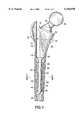
- FIG. 1is a partially sectioned elevational view showing a prosthetic implant component constructed in accordance with the invention and implanted within a natural bone;
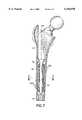
- FIG. 2is an exploded elevational view of the component
- FIG. 3is an enlarged cross-sectional view taken along line 3--3 of FIG. 1;
- FIG. 4is a partially sectioned elevational view of an alternate prosthetic implant component
- FIG. 5is an enlarged cross-sectional view taken along line 5--5 of FIG. 4;
- FIG. 6is an elevational view of an alternate part of the component
- FIG. 7is a partially sectioned elevational view of another alternate prosthetic implant component
- FIG. 8is an exploded elevational view of the component of FIG. 7;
- FIG. 9is an enlarged cross-sectional view taken along line 9--9 of FIG. 7;
- FIG. 10is a cross-sectional view similar to FIG. 9 and showing another embodiment of the invention.
- FIG. 11is a pictorial perspective view of a plurality of component parts in a kit of component parts for use in connection with the embodiment of FIG. 10.
- Femoral component 10is shown implanted at an implant site 12 in the proximal femur 14 of a natural femur 16 having an outer shell of cortical bone 18, inner cancellous bone 20 and calcar 22.
- the illustrated site 12is deficient in natural bone; that is, as a result of either injury or disease, or revision surgery, the natural bone available at the site 12 is inadequate to support a conventional femoral component of a replacement hip joint with sufficient stability and desirable structural integrity and composition.
- Femoral component 10is constructed in accordance with the present invention and provides a reliable and effective component for implant at site 12.
- femoral component 10has a proximal portion 30 which includes an affixation surface 32 and a neck 34 for carrying a selectively attached spherical head 36, which replaces a natural element of the natural hip joint, for engagement with either the natural acetabulum or an acetabular prosthesis for articulation in a hip replacement, all in a now conventional manner.
- a distal portion 40is provided for securement within a recess 42 in the natural bone of the femur 16, adjacent the joint being replaced.
- the recess 42has an internal surface 44 and is relatively large, extending transversely into the cortical bone 18, as a result of the site 12 being deficient in natural bone, leaving relatively less natural bone for support of the femoral component 10.
- the distal portion 40has a stem 46 which includes an elongate core 48 extending axially along the distal portion 40 and received within the recess 42.
- the core 48has a generally cylindrical configuration and includes an external surface 50 spaced transversely from and confronting the internal surface 44 of the recess 42. While the larger dimensions of recess 42 could be accommodated with a femoral component of conventional construction, such a conventional construction would include a stem of corresponding larger dimensions resulting in undesirable stiffness and concomitant undesirable loading of the natural bone.
- An allograftis shown in the form of a sleeve 60 of natural bone interposed between the core 48 and the internal surface 44 of the recess 42.
- Sleeve 60has a generally tubular configuration which includes an annular cross-sectional configuration and an inner securement surface 62 for gripping the core 48, along the external surface 50, to secure the sleeve 60 in place upon the core 48.
- An outer locator surface 64engages the internal surface 44 of the recess 42 and locates the core 48 transversely within the recess 42.
- proximal portion 30 of the femoral component 10is a biocompatible metal, such as titanium or a titanium alloy, and core 48 also is constructed of that preferred material; however, in order to attain effective support and securement of the femoral component 10 at bone deficient site 12, the core 48 is reduced in radial, or transverse dimensions, relative to the radial, or transverse extent of recess 42, so as to enable the interposition of the allograft in the form of sleeve 60.
- femoral component 10is comprised of assembled component parts, including a metallic component part 66, which includes the proximal portion 30 and core 48, the spherical head 36, and the allograft in the form of sleeve 60.
- the natural bone of the allograft provided by sleeve 60will incorporate over time with the natural bone existing at the site 12, for establishing a bone structure adequate to support the femoral component 10 at the site 12.
- use of the allograftprovides a more flexible prosthetic construct for desirable loading characteristics.
- incorporation of the allograftwill increase the amount of natural bone available for long-term performance, as well as for any additional surgical procedures which may become necessary.
- the natural bone of the sleeve 60may be supplemented, if desired, with growth factors or medicaments.
- a sleeve 60 of appropriate dimensionsis selected for location along the core 48 of the femoral component 10.
- the selected sleeve 60is slipped over the core 48 and secured in place on the core 48 prior to inserting the assembled sleeve 60 and core 48 into the recess 42.
- a surgeonis provided with a kit of component parts which, in addition to including a selection of component parts 66 and spherical heads 36 of different sizes, includes a plurality of sleeves 60 having different dimensions so as to enable the selection of a sleeve 60, interoperatively, for assembly with the core 48 of a selected component part 66 to accommodate the particular prepared recess 42 at the implant site 12.
- the relative dimensions of the external surface 50 of the core 48 and the inner securement surface 62 of each sleeve 60is such that upon engagement of the selected sleeve 60 with the core 48, the sleeve 60 grips the core 48 and is secured in place upon the core 48.
- an alternate femoral component 70is constructed in a manner similar to femoral component 10, and includes a distal portion 72 with a stem 74 having an elongate core 76 which carries an allograft in the form of a sleeve 80 affixed to the core 76.
- the external surface 82 of the core 76is provided with projections illustrated in the form of splines 84 extending transversely from the external surface 82 to pointed crests 86, and extending axially along the core 76 to engage the inner securement surface 88 of the sleeve 80 and secure the sleeve 80 against movement along the core 76 when the sleeve 80 is in place on the core 76.
- the engagement of the splines 84 with the sleeve 80assures that in the preferred procedure the sleeve 80 is secured in place upon the core 76 prior to insertion of the core 76 into the recess 42 of the proximal femur and remains in place during insertion of the core 76 into the recess 42 and proper seating of the femoral component 70 at the implant site 12.
- a sleeve 90is constructed similar to sleeves 60 and 80; however, in order to enhance the engagement of the outer locator surface 92 of the sleeve 90 with the internal surface 44 of the recess 42 (see FIG. 1), and to promote incorporation along the engaged outer locator surface 92 of the sleeve 90 and the internal surface 44 of the recess 42, the outer locator surface 92 is textured, as by knurling or the like as shown at 94.
- a plurality of allograftsare provided in the form of a plurality of sleeves 100 each having an axial length relatively shorter than the sleeves 60, 80 and 90 described above.
- Selected sleeves 100are strung upon the core 48 of the distal portion 40 to establish an alternate femoral component 110 in which the full allograft is in the form of a plurality of sleeves 100 affixed to the core 48.
- the ability to select multiple sleeves 100 from a plurality of such sleeves 100 supplied in a kit of component partsenables a surgeon to accommodate, interoperatively, a variety of conditions encountered at particular implant sites.
- variations in transverse dimensions of the recess 42 along the axial extent of core 48can be accommodated by placing sleeves 100 of different transverse dimensions at different axial locations along the core 48.
- differences in axial lengthcan be accommodated interoperatively by selecting sleeves 100 of appropriate length.
- allografts provided in the form of shorter sleeves 100are more readily available.
- the selected sleeves 100preferably are affixed to the core 48 prior to insertion of the core 48 into the prepared recess 42 in the proximal femur 14, as described above.
- a plurality of sleeves 120each include an inner securement surface 122 and an outer locator surface 124; however, rather than being concentric, the inner securement surface 122 and the outer locator surface 124 are eccentric so as to be offset relative to one another.
- a surgeonis provided with further interoperative options for accommodating conditions encountered at a particular implant site. For example, should the proximal femur be curved along the length of the femur, the surgeon may select and assemble sleeves 120 upon core 48 oriented so as to conform the composite contour of the outer locator surfaces 124 of the selected sleeves 120 to the curved configuration of the recess within which the stem of the femoral component is to be inserted.
- the present inventionattains all of the objects and advantages summarized above, namely: Enables successful replacement of a natural joint at a site in the body which suffers from a more severe deficiency in natural bone; facilitates revision surgery wherein a previously implanted prosthetic joint component is removed and replaced; provides a surgeon with a wider range of options in replacing a joint at a bone deficient site in the body; enables increased versatility in either the initial replacement of a natural joint or in a revision; increases accuracy in effecting replacement of a natural joint; provides increased stability and structural integrity at an implant site; provides a prosthetic implant of more desirable structure and composition for accommodating a wider variety of conditions encountered at an implant site; provides a prosthetic implant which exhibits exemplary performance over an extended service life.
Landscapes
- Health & Medical Sciences (AREA)
- Orthopedic Medicine & Surgery (AREA)
- Cardiology (AREA)
- Oral & Maxillofacial Surgery (AREA)
- Transplantation (AREA)
- Engineering & Computer Science (AREA)
- Biomedical Technology (AREA)
- Heart & Thoracic Surgery (AREA)
- Vascular Medicine (AREA)
- Life Sciences & Earth Sciences (AREA)
- Animal Behavior & Ethology (AREA)
- General Health & Medical Sciences (AREA)
- Public Health (AREA)
- Veterinary Medicine (AREA)
- Prostheses (AREA)
Abstract
Description
Claims (29)
Priority Applications (1)
| Application Number | Priority Date | Filing Date | Title |
|---|---|---|---|
| US09/277,672US6156070A (en) | 1999-03-26 | 1999-03-26 | Allograft prosthetic joints and method |
Applications Claiming Priority (1)
| Application Number | Priority Date | Filing Date | Title |
|---|---|---|---|
| US09/277,672US6156070A (en) | 1999-03-26 | 1999-03-26 | Allograft prosthetic joints and method |
Publications (1)
| Publication Number | Publication Date |
|---|---|
| US6156070Atrue US6156070A (en) | 2000-12-05 |
Family
ID=23061894
Family Applications (1)
| Application Number | Title | Priority Date | Filing Date |
|---|---|---|---|
| US09/277,672Expired - LifetimeUS6156070A (en) | 1999-03-26 | 1999-03-26 | Allograft prosthetic joints and method |
Country Status (1)
| Country | Link |
|---|---|
| US (1) | US6156070A (en) |
Cited By (76)
| Publication number | Priority date | Publication date | Assignee | Title |
|---|---|---|---|---|
| US20020029084A1 (en)* | 1998-08-03 | 2002-03-07 | Paul David C. | Bone implants with central chambers |
| US6361565B1 (en)* | 1991-08-12 | 2002-03-26 | Peter M. Bonutti | Expandable hip implant |
| US20020055755A1 (en)* | 1990-06-28 | 2002-05-09 | Bonutti Peter M. | Apparatus and method for tissue removal |
| US6503277B2 (en) | 1991-08-12 | 2003-01-07 | Peter M. Bonutti | Method of transplanting human body tissue |
| US6656226B2 (en)* | 2000-02-16 | 2003-12-02 | Korea Advanced Institute Of Science And Technology | Plastic jacket for a cementless artificial joint stem and artificial joint having the jacket |
| US20040028718A1 (en)* | 2002-06-27 | 2004-02-12 | Ferree Bret A. | Arthroplasty devices with resorbable component |
| US6692531B1 (en)* | 1999-06-09 | 2004-02-17 | Korea Advanced Institute Of Science And Technology | Prosthetic stem with cement sleeve |
| US6986788B2 (en) | 1998-01-30 | 2006-01-17 | Synthes (U.S.A.) | Intervertebral allograft spacer |
| US6990982B1 (en) | 1990-06-28 | 2006-01-31 | Bonutti Ip, Llc | Method for harvesting and processing cells from tissue fragments |
| US7115146B2 (en) | 2000-03-22 | 2006-10-03 | Boyer Ii Michael L | Multipiece implants formed of bone material |
| US7226482B2 (en) | 2003-09-02 | 2007-06-05 | Synthes (U.S.A.) | Multipiece allograft implant |
| US7232464B2 (en) | 2002-02-19 | 2007-06-19 | Synthes (Usa) | Intervertebral implant |
| US7300465B2 (en) | 1998-01-30 | 2007-11-27 | Synthes (U.S.A.) | Intervertebral allograft spacer |
| US7445639B2 (en) | 2001-02-23 | 2008-11-04 | Biomet Manufacturing Corp. | Knee joint prosthesis |
| US7488324B1 (en) | 2003-12-08 | 2009-02-10 | Biomet Manufacturing Corporation | Femoral guide for implanting a femoral knee prosthesis |
| US7497874B1 (en) | 2001-02-23 | 2009-03-03 | Biomet Manufacturing Corp. | Knee joint prosthesis |
| US7695520B2 (en) | 2006-05-31 | 2010-04-13 | Biomet Manufacturing Corp. | Prosthesis and implementation system |
| US7695479B1 (en) | 2005-04-12 | 2010-04-13 | Biomet Manufacturing Corp. | Femoral sizer |
| US7780672B2 (en) | 2006-02-27 | 2010-08-24 | Biomet Manufacturing Corp. | Femoral adjustment device and associated method |
| US7789885B2 (en) | 2003-01-15 | 2010-09-07 | Biomet Manufacturing Corp. | Instrumentation for knee resection |
| US7837690B2 (en) | 2003-01-15 | 2010-11-23 | Biomet Manufacturing Corp. | Method and apparatus for less invasive knee resection |
| US7846207B2 (en) | 2003-02-06 | 2010-12-07 | Synthes Usa, Llc | Intervertebral implant |
| US7887542B2 (en) | 2003-01-15 | 2011-02-15 | Biomet Manufacturing Corp. | Method and apparatus for less invasive knee resection |
| US20110202141A1 (en)* | 2010-02-18 | 2011-08-18 | Biomet Manufacturing Corp. | Method and apparatus for augmenting bone defects |
| US20110208189A1 (en)* | 2005-02-22 | 2011-08-25 | Tecres S.P.A. | Disposable device for treatment of infections of human limbs |
| US8043377B2 (en) | 2006-09-02 | 2011-10-25 | Osprey Biomedical, Inc. | Implantable intervertebral fusion device |
| US8070752B2 (en) | 2006-02-27 | 2011-12-06 | Biomet Manufacturing Corp. | Patient specific alignment guide and inter-operative adjustment |
| US8157869B2 (en) | 2007-01-10 | 2012-04-17 | Biomet Manufacturing Corp. | Knee joint prosthesis system and method for implantation |
| US8163028B2 (en) | 2007-01-10 | 2012-04-24 | Biomet Manufacturing Corp. | Knee joint prosthesis system and method for implantation |
| US8187280B2 (en) | 2007-10-10 | 2012-05-29 | Biomet Manufacturing Corp. | Knee joint prosthesis system and method for implantation |
| WO2012072111A1 (en)* | 2010-11-30 | 2012-06-07 | Smith & Nephew Orthopaedics Ag | Orthopaedic implant |
| US8265949B2 (en) | 2007-09-27 | 2012-09-11 | Depuy Products, Inc. | Customized patient surgical plan |
| US20120245704A1 (en)* | 2011-03-21 | 2012-09-27 | Ronald Childs | Sleeve for bone fixation device |
| US8328873B2 (en) | 2007-01-10 | 2012-12-11 | Biomet Manufacturing Corp. | Knee joint prosthesis system and method for implantation |
| US8343159B2 (en) | 2007-09-30 | 2013-01-01 | Depuy Products, Inc. | Orthopaedic bone saw and method of use thereof |
| US8357111B2 (en) | 2007-09-30 | 2013-01-22 | Depuy Products, Inc. | Method and system for designing patient-specific orthopaedic surgical instruments |
| US8535386B2 (en) | 2010-10-21 | 2013-09-17 | Howmedica Osteonics Corp. | Stem with pressfit porous element |
| US8540774B2 (en) | 2007-11-16 | 2013-09-24 | DePuy Synthes Products, LLC | Low profile intervertebral implant |
| US8551100B2 (en) | 2003-01-15 | 2013-10-08 | Biomet Manufacturing, Llc | Instrumentation for knee resection |
| US8562616B2 (en) | 2007-10-10 | 2013-10-22 | Biomet Manufacturing, Llc | Knee joint prosthesis system and method for implantation |
| US8747439B2 (en) | 2000-03-13 | 2014-06-10 | P Tech, Llc | Method of using ultrasonic vibration to secure body tissue with fastening element |
| US8808329B2 (en) | 1998-02-06 | 2014-08-19 | Bonutti Skeletal Innovations Llc | Apparatus and method for securing a portion of a body |
| US8814902B2 (en) | 2000-05-03 | 2014-08-26 | Bonutti Skeletal Innovations Llc | Method of securing body tissue |
| US8845699B2 (en) | 1999-08-09 | 2014-09-30 | Bonutti Skeletal Innovations Llc | Method of securing tissue |
| US9039775B2 (en) | 2003-03-31 | 2015-05-26 | DePuy Synthes Products, Inc. | Spinal fixation plates |
| US9192419B2 (en) | 2008-11-07 | 2015-11-24 | DePuy Synthes Products, Inc. | Zero-profile interbody spacer and coupled plate assembly |
| US9220604B2 (en) | 2010-12-21 | 2015-12-29 | DePuy Synthes Products, Inc. | Intervertebral implants, systems, and methods of use |
| US9241809B2 (en) | 2010-12-21 | 2016-01-26 | DePuy Synthes Products, Inc. | Intervertebral implants, systems, and methods of use |
| US9700329B2 (en) | 2006-02-27 | 2017-07-11 | Biomet Manufacturing, Llc | Patient-specific orthopedic instruments |
| US9743935B2 (en) | 2011-03-07 | 2017-08-29 | Biomet Manufacturing, Llc | Patient-specific femoral version guide |
| US9770238B2 (en) | 2001-12-03 | 2017-09-26 | P Tech, Llc | Magnetic positioning apparatus |
| US9795399B2 (en) | 2006-06-09 | 2017-10-24 | Biomet Manufacturing, Llc | Patient-specific knee alignment guide and associated method |
| US9867718B2 (en) | 2014-10-22 | 2018-01-16 | DePuy Synthes Products, Inc. | Intervertebral implants, systems, and methods of use |
| US9883951B2 (en) | 2012-08-30 | 2018-02-06 | Interventional Spine, Inc. | Artificial disc |
| US9913734B2 (en) | 2006-02-27 | 2018-03-13 | Biomet Manufacturing, Llc | Patient-specific acetabular alignment guides |
| US9968376B2 (en) | 2010-11-29 | 2018-05-15 | Biomet Manufacturing, Llc | Patient-specific orthopedic instruments |
| US10159498B2 (en) | 2008-04-16 | 2018-12-25 | Biomet Manufacturing, Llc | Method and apparatus for manufacturing an implant |
| US10206695B2 (en) | 2006-02-27 | 2019-02-19 | Biomet Manufacturing, Llc | Femoral acetabular impingement guide |
| US10278711B2 (en) | 2006-02-27 | 2019-05-07 | Biomet Manufacturing, Llc | Patient-specific femoral guide |
| US10390845B2 (en) | 2006-02-27 | 2019-08-27 | Biomet Manufacturing, Llc | Patient-specific shoulder guide |
| US10426492B2 (en) | 2006-02-27 | 2019-10-01 | Biomet Manufacturing, Llc | Patient specific alignment guide with cutting surface and laser indicator |
| US10507029B2 (en) | 2006-02-27 | 2019-12-17 | Biomet Manufacturing, Llc | Patient-specific acetabular guides and associated instruments |
| US10512548B2 (en) | 2006-02-27 | 2019-12-24 | DePuy Synthes Products, Inc. | Intervertebral implant with fixation geometry |
| US10603179B2 (en) | 2006-02-27 | 2020-03-31 | Biomet Manufacturing, Llc | Patient-specific augments |
| US10722310B2 (en) | 2017-03-13 | 2020-07-28 | Zimmer Biomet CMF and Thoracic, LLC | Virtual surgery planning system and method |
| US10743937B2 (en) | 2006-02-27 | 2020-08-18 | Biomet Manufacturing, Llc | Backup surgical instrument system and method |
| USD901014S1 (en) | 2019-08-12 | 2020-11-03 | Ortho Development Corporation | Porous implant |
| USD901012S1 (en) | 2019-08-12 | 2020-11-03 | Ortho Development Corporation | Porous implant |
| USD901013S1 (en) | 2019-08-12 | 2020-11-03 | Ortho Development Corporation | Porous implant |
| US11051829B2 (en) | 2018-06-26 | 2021-07-06 | DePuy Synthes Products, Inc. | Customized patient-specific orthopaedic surgical instrument |
| US11498124B1 (en) | 2019-11-25 | 2022-11-15 | Ortho Development Corporation | Method for sintering porous structures from powder using additive manufacturing |
| US11534313B2 (en) | 2006-02-27 | 2022-12-27 | Biomet Manufacturing, Llc | Patient-specific pre-operative planning |
| US11554019B2 (en) | 2007-04-17 | 2023-01-17 | Biomet Manufacturing, Llc | Method and apparatus for manufacturing an implant |
| US11565021B1 (en) | 2019-08-12 | 2023-01-31 | Ortho Development Corporation | Composite structure porous implant for replacing bone stock |
| USD1090843S1 (en)* | 2023-10-13 | 2025-08-26 | Hefei Longshore Tech Co., Ltd | Femoral stem and neck prosthesis assembly |
| US12434302B2 (en) | 2019-11-25 | 2025-10-07 | Ortho Development Corporation | Method for manufacturing porous structures using additive manufacturing |
Citations (17)
| Publication number | Priority date | Publication date | Assignee | Title |
|---|---|---|---|---|
| US3906550A (en)* | 1973-12-27 | 1975-09-23 | William Rostoker | Prosthetic device having a porous fiber metal structure |
| EP0378044A1 (en)* | 1989-01-10 | 1990-07-18 | GebràDer Sulzer Aktiengesellschaft | Flat stem for a femoral head prosthesis |
| US4950296A (en)* | 1988-04-07 | 1990-08-21 | Mcintyre Jonathan L | Bone grafting units |
| US5035714A (en)* | 1989-07-18 | 1991-07-30 | Sulzer Brothers Limited | Reinforcement for a bone cement bed |
| US5053049A (en)* | 1985-05-29 | 1991-10-01 | Baxter International | Flexible prostheses of predetermined shapes and process for making same |
| US5061286A (en)* | 1989-08-18 | 1991-10-29 | Osteotech, Inc. | Osteoprosthetic implant |
| FR2666984A3 (en)* | 1990-09-21 | 1992-03-27 | Impact | Femoral shaft for a total hip prosthesis with primary fixation |
| US5112354A (en)* | 1989-11-16 | 1992-05-12 | Northwestern University | Bone allograft material and method |
| US5133772A (en)* | 1990-01-17 | 1992-07-28 | Osteonics Corporation | Femoral implant for hip arthroplasty |
| US5258034A (en)* | 1989-02-15 | 1993-11-02 | Furlong Ronald J | Femoral prosthesis |
| EP0623321A1 (en)* | 1993-05-07 | 1994-11-09 | Bristol-Myers Squibb Company | Femoral part of a hip joint prosthesis |
| US5458653A (en)* | 1991-07-15 | 1995-10-17 | Smith & Nephew Richards, Inc. | Prosthetic implants with bioabsorbable coatings |
| US5480451A (en)* | 1992-08-17 | 1996-01-02 | Eska Medical Gmbh & Co. | Angularly adjustable offset spherical head endoprosthesis |
| US5490853A (en)* | 1994-06-08 | 1996-02-13 | Intermedics Orthopedics, Inc. | Orthopedic bone plug cutter |
| US5571193A (en)* | 1992-03-12 | 1996-11-05 | Kampner; Stanley L. | Implant with reinforced resorbable stem |
| US5697932A (en)* | 1994-11-09 | 1997-12-16 | Osteonics Corp. | Bone graft delivery system and method |
| US5814084A (en)* | 1996-01-16 | 1998-09-29 | University Of Florida Tissue Bank, Inc. | Diaphysial cortical dowel |
- 1999
- 1999-03-26USUS09/277,672patent/US6156070A/ennot_activeExpired - Lifetime
Patent Citations (18)
| Publication number | Priority date | Publication date | Assignee | Title |
|---|---|---|---|---|
| US3906550A (en)* | 1973-12-27 | 1975-09-23 | William Rostoker | Prosthetic device having a porous fiber metal structure |
| US5053049A (en)* | 1985-05-29 | 1991-10-01 | Baxter International | Flexible prostheses of predetermined shapes and process for making same |
| US4950296A (en)* | 1988-04-07 | 1990-08-21 | Mcintyre Jonathan L | Bone grafting units |
| EP0378044A1 (en)* | 1989-01-10 | 1990-07-18 | GebràDer Sulzer Aktiengesellschaft | Flat stem for a femoral head prosthesis |
| US5258034A (en)* | 1989-02-15 | 1993-11-02 | Furlong Ronald J | Femoral prosthesis |
| US5035714A (en)* | 1989-07-18 | 1991-07-30 | Sulzer Brothers Limited | Reinforcement for a bone cement bed |
| US5061286A (en)* | 1989-08-18 | 1991-10-29 | Osteotech, Inc. | Osteoprosthetic implant |
| US5112354A (en)* | 1989-11-16 | 1992-05-12 | Northwestern University | Bone allograft material and method |
| US5133772A (en)* | 1990-01-17 | 1992-07-28 | Osteonics Corporation | Femoral implant for hip arthroplasty |
| US5133772B1 (en)* | 1990-01-17 | 1997-08-05 | Osteonics Corp | Femoral implant for hip arthroplasty |
| FR2666984A3 (en)* | 1990-09-21 | 1992-03-27 | Impact | Femoral shaft for a total hip prosthesis with primary fixation |
| US5458653A (en)* | 1991-07-15 | 1995-10-17 | Smith & Nephew Richards, Inc. | Prosthetic implants with bioabsorbable coatings |
| US5571193A (en)* | 1992-03-12 | 1996-11-05 | Kampner; Stanley L. | Implant with reinforced resorbable stem |
| US5480451A (en)* | 1992-08-17 | 1996-01-02 | Eska Medical Gmbh & Co. | Angularly adjustable offset spherical head endoprosthesis |
| EP0623321A1 (en)* | 1993-05-07 | 1994-11-09 | Bristol-Myers Squibb Company | Femoral part of a hip joint prosthesis |
| US5490853A (en)* | 1994-06-08 | 1996-02-13 | Intermedics Orthopedics, Inc. | Orthopedic bone plug cutter |
| US5697932A (en)* | 1994-11-09 | 1997-12-16 | Osteonics Corp. | Bone graft delivery system and method |
| US5814084A (en)* | 1996-01-16 | 1998-09-29 | University Of Florida Tissue Bank, Inc. | Diaphysial cortical dowel |
Non-Patent Citations (2)
| Title |
|---|
| S.J. Incavo et al, "Allograft-Host Mismatch in Revision Total Hip Replacement" Orthopaedic Review, Oct. 1994, 832-36. |
| S.J. Incavo et al, Allograft Host Mismatch in Revision Total Hip Replacement Orthopaedic Review , Oct. 1994, 832 36.* |
Cited By (159)
| Publication number | Priority date | Publication date | Assignee | Title |
|---|---|---|---|---|
| US6990982B1 (en) | 1990-06-28 | 2006-01-31 | Bonutti Ip, Llc | Method for harvesting and processing cells from tissue fragments |
| US7896880B2 (en) | 1990-06-28 | 2011-03-01 | P Tech, Llc | Apparatus and method for tissue removal |
| US7134437B2 (en) | 1990-06-28 | 2006-11-14 | Bonutti Ip, Llc | Method for utilizing human tissue |
| US20020055755A1 (en)* | 1990-06-28 | 2002-05-09 | Bonutti Peter M. | Apparatus and method for tissue removal |
| US6860904B2 (en) | 1991-08-12 | 2005-03-01 | Bonutti 2003 Trust-A | Method for tissue grafting |
| US6989029B2 (en) | 1991-08-12 | 2006-01-24 | Bonutti Ip, Llc | Tissue cage |
| US6630000B1 (en) | 1991-08-12 | 2003-10-07 | Bonutti 2003 Trust-A | Method of using body tissue |
| US6638309B2 (en) | 1991-08-12 | 2003-10-28 | Bonutti 2003 Trust A | Method of using body tissue |
| US7462200B2 (en) | 1991-08-12 | 2008-12-09 | Marctec, Llc | Method for tissue grafting |
| US6361565B1 (en)* | 1991-08-12 | 2002-03-26 | Peter M. Bonutti | Expandable hip implant |
| US7727283B2 (en) | 1991-08-12 | 2010-06-01 | P Tech, Llc. | Tissue stabilizing implant method |
| US6702856B2 (en) | 1991-08-12 | 2004-03-09 | The Bonutti 2003 Trust A | Method of using Tissue |
| US6736853B2 (en) | 1991-08-12 | 2004-05-18 | The Bonutti 2003 Trust A | Method of using tissue cage |
| US6776938B2 (en) | 1991-08-12 | 2004-08-17 | Bonutti 2003 Trust-A | Method for forming implant containing tissue |
| US20020040246A1 (en)* | 1991-08-12 | 2002-04-04 | Bonutti Peter M. | Tissue press and system |
| US6905517B2 (en) | 1991-08-12 | 2005-06-14 | Bonutti Ip, Llp | Tissue grafting material |
| US7070557B2 (en) | 1991-08-12 | 2006-07-04 | Marctec, Llc | Tissue graft material and method of making |
| US20030050708A1 (en)* | 1991-08-12 | 2003-03-13 | Bonutti Peter M. | Tissue grafting material |
| US6503277B2 (en) | 1991-08-12 | 2003-01-07 | Peter M. Bonutti | Method of transplanting human body tissue |
| US6986788B2 (en) | 1998-01-30 | 2006-01-17 | Synthes (U.S.A.) | Intervertebral allograft spacer |
| US7300465B2 (en) | 1998-01-30 | 2007-11-27 | Synthes (U.S.A.) | Intervertebral allograft spacer |
| US8808329B2 (en) | 1998-02-06 | 2014-08-19 | Bonutti Skeletal Innovations Llc | Apparatus and method for securing a portion of a body |
| US7087082B2 (en) | 1998-08-03 | 2006-08-08 | Synthes (Usa) | Bone implants with central chambers |
| US20020029084A1 (en)* | 1998-08-03 | 2002-03-07 | Paul David C. | Bone implants with central chambers |
| US6692531B1 (en)* | 1999-06-09 | 2004-02-17 | Korea Advanced Institute Of Science And Technology | Prosthetic stem with cement sleeve |
| US8845699B2 (en) | 1999-08-09 | 2014-09-30 | Bonutti Skeletal Innovations Llc | Method of securing tissue |
| US6656226B2 (en)* | 2000-02-16 | 2003-12-02 | Korea Advanced Institute Of Science And Technology | Plastic jacket for a cementless artificial joint stem and artificial joint having the jacket |
| US8747439B2 (en) | 2000-03-13 | 2014-06-10 | P Tech, Llc | Method of using ultrasonic vibration to secure body tissue with fastening element |
| US7115146B2 (en) | 2000-03-22 | 2006-10-03 | Boyer Ii Michael L | Multipiece implants formed of bone material |
| US8814902B2 (en) | 2000-05-03 | 2014-08-26 | Bonutti Skeletal Innovations Llc | Method of securing body tissue |
| US7445639B2 (en) | 2001-02-23 | 2008-11-04 | Biomet Manufacturing Corp. | Knee joint prosthesis |
| US7497874B1 (en) | 2001-02-23 | 2009-03-03 | Biomet Manufacturing Corp. | Knee joint prosthesis |
| US9770238B2 (en) | 2001-12-03 | 2017-09-26 | P Tech, Llc | Magnetic positioning apparatus |
| US7618456B2 (en) | 2002-02-19 | 2009-11-17 | Synthes Usa, Llc | Intervertebral implant |
| US7232464B2 (en) | 2002-02-19 | 2007-06-19 | Synthes (Usa) | Intervertebral implant |
| US9572681B2 (en) | 2002-02-19 | 2017-02-21 | DePuy Synthes Products, Inc. | Intervertebral implant |
| US10492922B2 (en) | 2002-02-19 | 2019-12-03 | DePuy Synthes Products, Inc. | Intervertebral implant |
| US7192448B2 (en)* | 2002-06-27 | 2007-03-20 | Ferree Bret A | Arthroplasty devices with resorbable component |
| US20040028718A1 (en)* | 2002-06-27 | 2004-02-12 | Ferree Bret A. | Arthroplasty devices with resorbable component |
| US9693788B2 (en) | 2003-01-15 | 2017-07-04 | Biomet Manufacturing, Llc | Instrumentation for knee resection |
| US7789885B2 (en) | 2003-01-15 | 2010-09-07 | Biomet Manufacturing Corp. | Instrumentation for knee resection |
| US7887542B2 (en) | 2003-01-15 | 2011-02-15 | Biomet Manufacturing Corp. | Method and apparatus for less invasive knee resection |
| US9023053B2 (en) | 2003-01-15 | 2015-05-05 | Biomet Manufacturing, Llc | Instrumentation for knee resection |
| US7837690B2 (en) | 2003-01-15 | 2010-11-23 | Biomet Manufacturing Corp. | Method and apparatus for less invasive knee resection |
| US8551100B2 (en) | 2003-01-15 | 2013-10-08 | Biomet Manufacturing, Llc | Instrumentation for knee resection |
| US8518047B2 (en) | 2003-01-15 | 2013-08-27 | Biomet Manufacturing, Llc | Method and apparatus for less invasive knee resection |
| US8870883B2 (en) | 2003-01-15 | 2014-10-28 | Biomet Manufacturing, Llc | Method for less invasive knee resection |
| US10064740B2 (en) | 2003-02-06 | 2018-09-04 | DePuy Synthes Products, LLC | Intervertebral implant |
| US8709085B2 (en) | 2003-02-06 | 2014-04-29 | DePuy Synthes Products, LLC | Intervertebral implant |
| US8715354B2 (en) | 2003-02-06 | 2014-05-06 | DePuy Synthes Products, LLC | Intervertebral implant |
| US9463097B2 (en) | 2003-02-06 | 2016-10-11 | DePuy Synthes Products, Inc. | Intervertebral implant |
| US8764831B2 (en) | 2003-02-06 | 2014-07-01 | DePuy Synthes Products, LLC | Intervertebral implant |
| US7862616B2 (en) | 2003-02-06 | 2011-01-04 | Synthes Usa, Llc | Intervertebral implant |
| US10660765B2 (en) | 2003-02-06 | 2020-05-26 | DePuy Synthes Products, Inc. | Intervertebral implant |
| US7846207B2 (en) | 2003-02-06 | 2010-12-07 | Synthes Usa, Llc | Intervertebral implant |
| US9320549B2 (en) | 2003-03-31 | 2016-04-26 | DePuy Synthes Products, Inc. | Spinal fixation plates |
| US9039775B2 (en) | 2003-03-31 | 2015-05-26 | DePuy Synthes Products, Inc. | Spinal fixation plates |
| US7601173B2 (en) | 2003-09-02 | 2009-10-13 | Synthes Usa, Llc | Multipiece allograft implant |
| US7226482B2 (en) | 2003-09-02 | 2007-06-05 | Synthes (U.S.A.) | Multipiece allograft implant |
| US8834486B2 (en) | 2003-12-08 | 2014-09-16 | Biomet Manufacturing, Llc | Femoral guide for implanting a femoral knee prosthesis |
| US7488324B1 (en) | 2003-12-08 | 2009-02-10 | Biomet Manufacturing Corporation | Femoral guide for implanting a femoral knee prosthesis |
| US8123758B2 (en) | 2003-12-08 | 2012-02-28 | Biomet Manufacturing Corp. | Femoral guide for implanting a femoral knee prosthesis |
| US9452001B2 (en)* | 2005-02-22 | 2016-09-27 | Tecres S.P.A. | Disposable device for treatment of infections of human limbs |
| US20110208189A1 (en)* | 2005-02-22 | 2011-08-25 | Tecres S.P.A. | Disposable device for treatment of infections of human limbs |
| US7695479B1 (en) | 2005-04-12 | 2010-04-13 | Biomet Manufacturing Corp. | Femoral sizer |
| US10426492B2 (en) | 2006-02-27 | 2019-10-01 | Biomet Manufacturing, Llc | Patient specific alignment guide with cutting surface and laser indicator |
| US10507029B2 (en) | 2006-02-27 | 2019-12-17 | Biomet Manufacturing, Llc | Patient-specific acetabular guides and associated instruments |
| US10206695B2 (en) | 2006-02-27 | 2019-02-19 | Biomet Manufacturing, Llc | Femoral acetabular impingement guide |
| US10278711B2 (en) | 2006-02-27 | 2019-05-07 | Biomet Manufacturing, Llc | Patient-specific femoral guide |
| US10390845B2 (en) | 2006-02-27 | 2019-08-27 | Biomet Manufacturing, Llc | Patient-specific shoulder guide |
| US7780672B2 (en) | 2006-02-27 | 2010-08-24 | Biomet Manufacturing Corp. | Femoral adjustment device and associated method |
| US9913734B2 (en) | 2006-02-27 | 2018-03-13 | Biomet Manufacturing, Llc | Patient-specific acetabular alignment guides |
| US11534313B2 (en) | 2006-02-27 | 2022-12-27 | Biomet Manufacturing, Llc | Patient-specific pre-operative planning |
| US10512548B2 (en) | 2006-02-27 | 2019-12-24 | DePuy Synthes Products, Inc. | Intervertebral implant with fixation geometry |
| US10603179B2 (en) | 2006-02-27 | 2020-03-31 | Biomet Manufacturing, Llc | Patient-specific augments |
| US8070752B2 (en) | 2006-02-27 | 2011-12-06 | Biomet Manufacturing Corp. | Patient specific alignment guide and inter-operative adjustment |
| US10743937B2 (en) | 2006-02-27 | 2020-08-18 | Biomet Manufacturing, Llc | Backup surgical instrument system and method |
| US11696837B2 (en) | 2006-02-27 | 2023-07-11 | DePuy Synthes Products, Inc. | Intervertebral implant with fixation geometry |
| US9700329B2 (en) | 2006-02-27 | 2017-07-11 | Biomet Manufacturing, Llc | Patient-specific orthopedic instruments |
| US7695520B2 (en) | 2006-05-31 | 2010-04-13 | Biomet Manufacturing Corp. | Prosthesis and implementation system |
| US9795399B2 (en) | 2006-06-09 | 2017-10-24 | Biomet Manufacturing, Llc | Patient-specific knee alignment guide and associated method |
| US11576689B2 (en) | 2006-06-09 | 2023-02-14 | Biomet Manufacturing, Llc | Patient-specific knee alignment guide and associated method |
| US10893879B2 (en) | 2006-06-09 | 2021-01-19 | Biomet Manufacturing, Llc | Patient-specific knee alignment guide and associated method |
| US10206697B2 (en) | 2006-06-09 | 2019-02-19 | Biomet Manufacturing, Llc | Patient-specific knee alignment guide and associated method |
| US8043377B2 (en) | 2006-09-02 | 2011-10-25 | Osprey Biomedical, Inc. | Implantable intervertebral fusion device |
| US8163028B2 (en) | 2007-01-10 | 2012-04-24 | Biomet Manufacturing Corp. | Knee joint prosthesis system and method for implantation |
| US8328873B2 (en) | 2007-01-10 | 2012-12-11 | Biomet Manufacturing Corp. | Knee joint prosthesis system and method for implantation |
| US8936648B2 (en) | 2007-01-10 | 2015-01-20 | Biomet Manufacturing, Llc | Knee joint prosthesis system and method for implantation |
| US8157869B2 (en) | 2007-01-10 | 2012-04-17 | Biomet Manufacturing Corp. | Knee joint prosthesis system and method for implantation |
| US8480751B2 (en) | 2007-01-10 | 2013-07-09 | Biomet Manufacturing, Llc | Knee joint prosthesis system and method for implantation |
| US11554019B2 (en) | 2007-04-17 | 2023-01-17 | Biomet Manufacturing, Llc | Method and apparatus for manufacturing an implant |
| US8265949B2 (en) | 2007-09-27 | 2012-09-11 | Depuy Products, Inc. | Customized patient surgical plan |
| US12070231B2 (en) | 2007-09-27 | 2024-08-27 | DePuy Synthes Products, Inc. | Customized patient surgical plan |
| US10028750B2 (en) | 2007-09-30 | 2018-07-24 | DePuy Synthes Products, Inc. | Apparatus and method for fabricating a customized patient-specific orthopaedic instrument |
| US10828046B2 (en) | 2007-09-30 | 2020-11-10 | DePuy Synthes Products, Inc. | Apparatus and method for fabricating a customized patient-specific orthopaedic instrument |
| US8343159B2 (en) | 2007-09-30 | 2013-01-01 | Depuy Products, Inc. | Orthopaedic bone saw and method of use thereof |
| US11931049B2 (en) | 2007-09-30 | 2024-03-19 | DePuy Synthes Products, Inc. | Apparatus and method for fabricating a customized patient-specific orthopaedic instrument |
| US11696768B2 (en) | 2007-09-30 | 2023-07-11 | DePuy Synthes Products, Inc. | Apparatus and method for fabricating a customized patient-specific orthopaedic instrument |
| US8357166B2 (en) | 2007-09-30 | 2013-01-22 | Depuy Products, Inc. | Customized patient-specific instrumentation and method for performing a bone re-cut |
| US8377068B2 (en) | 2007-09-30 | 2013-02-19 | DePuy Synthes Products, LLC. | Customized patient-specific instrumentation for use in orthopaedic surgical procedures |
| US8357111B2 (en) | 2007-09-30 | 2013-01-22 | Depuy Products, Inc. | Method and system for designing patient-specific orthopaedic surgical instruments |
| US8398645B2 (en) | 2007-09-30 | 2013-03-19 | DePuy Synthes Products, LLC | Femoral tibial customized patient-specific orthopaedic surgical instrumentation |
| US8361076B2 (en) | 2007-09-30 | 2013-01-29 | Depuy Products, Inc. | Patient-customizable device and system for performing an orthopaedic surgical procedure |
| US9763793B2 (en) | 2007-10-10 | 2017-09-19 | Biomet Manufacturing, Llc | Knee joint prosthesis system and method for implantation |
| US10736747B2 (en) | 2007-10-10 | 2020-08-11 | Biomet Manufacturing, Llc | Knee joint prosthesis system and method for implantation |
| US8187280B2 (en) | 2007-10-10 | 2012-05-29 | Biomet Manufacturing Corp. | Knee joint prosthesis system and method for implantation |
| US8562616B2 (en) | 2007-10-10 | 2013-10-22 | Biomet Manufacturing, Llc | Knee joint prosthesis system and method for implantation |
| US10543102B2 (en) | 2007-11-16 | 2020-01-28 | DePuy Synthes Products, Inc. | Low profile intervertebral implant |
| US9744049B2 (en) | 2007-11-16 | 2017-08-29 | DePuy Synthes Products, Inc. | Low profile intervertebral implant |
| US9005295B2 (en) | 2007-11-16 | 2015-04-14 | DePuy Synthes Products, LLC | Low profile intervertebral implant |
| US8540774B2 (en) | 2007-11-16 | 2013-09-24 | DePuy Synthes Products, LLC | Low profile intervertebral implant |
| US10137003B2 (en) | 2007-11-16 | 2018-11-27 | DePuy Synthes Products, Inc. | Low profile intervertebral implant |
| US10159498B2 (en) | 2008-04-16 | 2018-12-25 | Biomet Manufacturing, Llc | Method and apparatus for manufacturing an implant |
| US9414935B2 (en) | 2008-11-07 | 2016-08-16 | DePuy Synthes Products, Inc. | Zero-profile interbody spacer and coupled plate assembly |
| US9192419B2 (en) | 2008-11-07 | 2015-11-24 | DePuy Synthes Products, Inc. | Zero-profile interbody spacer and coupled plate assembly |
| US12263096B2 (en) | 2008-11-07 | 2025-04-01 | DePuy Synthes Products, Inc. | Zero-profile interbody spacer and coupled plate assembly |
| US10433976B2 (en) | 2008-11-07 | 2019-10-08 | DePuy Synthes Products, Inc. | Zero-profile interbody spacer and coupled plate assembly |
| US9402735B2 (en) | 2008-11-07 | 2016-08-02 | DePuy Synthes Products, Inc. | Zero-profile interbody spacer and coupled plate assembly |
| US10531960B2 (en) | 2008-11-07 | 2020-01-14 | DePuy Synthes Products, Inc. | Zero-profile interbody spacer and coupled plate assembly |
| US11517444B2 (en) | 2008-11-07 | 2022-12-06 | DePuy Synthes Products, Inc. | Zero-profile interbody spacer and coupled plate assembly |
| US11612492B2 (en) | 2008-11-07 | 2023-03-28 | DePuy Synthes Products, Inc. | Zero-profile interbody spacer and coupled plate assembly |
| US11324522B2 (en) | 2009-10-01 | 2022-05-10 | Biomet Manufacturing, Llc | Patient specific alignment guide with cutting surface and laser indicator |
| US20110202141A1 (en)* | 2010-02-18 | 2011-08-18 | Biomet Manufacturing Corp. | Method and apparatus for augmenting bone defects |
| US9289299B2 (en) | 2010-02-18 | 2016-03-22 | Biomet Manufacturing, Llc | Method and apparatus for augumenting bone defects |
| US8444699B2 (en)* | 2010-02-18 | 2013-05-21 | Biomet Manufacturing Corp. | Method and apparatus for augmenting bone defects |
| US10893876B2 (en) | 2010-03-05 | 2021-01-19 | Biomet Manufacturing, Llc | Method and apparatus for manufacturing an implant |
| US8535386B2 (en) | 2010-10-21 | 2013-09-17 | Howmedica Osteonics Corp. | Stem with pressfit porous element |
| US8926708B2 (en) | 2010-10-21 | 2015-01-06 | Howmedica Osteonics Corp. | Stem with pressfit porous element |
| US11234719B2 (en) | 2010-11-03 | 2022-02-01 | Biomet Manufacturing, Llc | Patient-specific shoulder guide |
| US9968376B2 (en) | 2010-11-29 | 2018-05-15 | Biomet Manufacturing, Llc | Patient-specific orthopedic instruments |
| WO2012072111A1 (en)* | 2010-11-30 | 2012-06-07 | Smith & Nephew Orthopaedics Ag | Orthopaedic implant |
| US9220604B2 (en) | 2010-12-21 | 2015-12-29 | DePuy Synthes Products, Inc. | Intervertebral implants, systems, and methods of use |
| US9241809B2 (en) | 2010-12-21 | 2016-01-26 | DePuy Synthes Products, Inc. | Intervertebral implants, systems, and methods of use |
| US11458027B2 (en) | 2010-12-21 | 2022-10-04 | DePuy Synthes Products, Inc. | Intervertebral implants, systems, and methods of use |
| US9848992B2 (en) | 2010-12-21 | 2017-12-26 | DePuy Synthes Products, Inc. | Intervertebral implants, systems, and methods of use |
| US10507117B2 (en) | 2010-12-21 | 2019-12-17 | DePuy Synthes Products, Inc. | Intervertebral implants, systems, and methods of use |
| US9743935B2 (en) | 2011-03-07 | 2017-08-29 | Biomet Manufacturing, Llc | Patient-specific femoral version guide |
| US9687278B2 (en)* | 2011-03-21 | 2017-06-27 | Ronald Childs | Sleeve for bone fixation device |
| US20170303973A1 (en)* | 2011-03-21 | 2017-10-26 | DePuy Synthes Products, Inc. | Sleeve for bone fixation device |
| US20120245704A1 (en)* | 2011-03-21 | 2012-09-27 | Ronald Childs | Sleeve for bone fixation device |
| US10729475B2 (en)* | 2011-03-21 | 2020-08-04 | Ronald C. Childs | Sleeve for bone fixation device |
| US20200323565A1 (en)* | 2011-03-21 | 2020-10-15 | Ronald C. Childs | Sleeve for bone fixation device |
| US11950812B2 (en)* | 2011-03-21 | 2024-04-09 | Ronald C. Childs | Sleeve for bone fixation device |
| US9883951B2 (en) | 2012-08-30 | 2018-02-06 | Interventional Spine, Inc. | Artificial disc |
| US9867718B2 (en) | 2014-10-22 | 2018-01-16 | DePuy Synthes Products, Inc. | Intervertebral implants, systems, and methods of use |
| US11540927B2 (en) | 2014-10-22 | 2023-01-03 | DePuy Synthes Products, Inc. | Intervertebral implants, systems, and methods of use |
| US10702394B2 (en) | 2014-10-22 | 2020-07-07 | DePuy Synthes Products, Inc. | Intervertebral implants, systems, and methods of use |
| US10130492B2 (en) | 2014-10-22 | 2018-11-20 | DePuy Synthes Products, Inc. | Intervertebral implants, systems, and methods of use |
| US10010432B2 (en) | 2014-10-22 | 2018-07-03 | DePuy Synthes Products, Inc. | Intervertebral implants, systems, and methods of use |
| US10722310B2 (en) | 2017-03-13 | 2020-07-28 | Zimmer Biomet CMF and Thoracic, LLC | Virtual surgery planning system and method |
| US11950786B2 (en) | 2018-06-26 | 2024-04-09 | DePuy Synthes Products, Inc. | Customized patient-specific orthopaedic surgical instrument |
| US11051829B2 (en) | 2018-06-26 | 2021-07-06 | DePuy Synthes Products, Inc. | Customized patient-specific orthopaedic surgical instrument |
| US11565021B1 (en) | 2019-08-12 | 2023-01-31 | Ortho Development Corporation | Composite structure porous implant for replacing bone stock |
| USD901013S1 (en) | 2019-08-12 | 2020-11-03 | Ortho Development Corporation | Porous implant |
| USD901014S1 (en) | 2019-08-12 | 2020-11-03 | Ortho Development Corporation | Porous implant |
| USD901012S1 (en) | 2019-08-12 | 2020-11-03 | Ortho Development Corporation | Porous implant |
| US11498124B1 (en) | 2019-11-25 | 2022-11-15 | Ortho Development Corporation | Method for sintering porous structures from powder using additive manufacturing |
| US12434302B2 (en) | 2019-11-25 | 2025-10-07 | Ortho Development Corporation | Method for manufacturing porous structures using additive manufacturing |
| USD1090843S1 (en)* | 2023-10-13 | 2025-08-26 | Hefei Longshore Tech Co., Ltd | Femoral stem and neck prosthesis assembly |
Similar Documents
| Publication | Publication Date | Title |
|---|---|---|
| US6156070A (en) | Allograft prosthetic joints and method | |
| AU769910B2 (en) | Modular stem and sleeve prosthesis | |
| US7153326B1 (en) | Method and apparatus for use of an offset stem connection | |
| US6682568B2 (en) | Modular femoral stem component for a hip joint prosthesis | |
| US5163961A (en) | Compression-fit hip prosthesis and procedures for implantation thereof | |
| US5601567A (en) | Method of sizing a femoral canal using a modular femoral trial hip replacement system | |
| US8021433B2 (en) | Modular long bone prosthesis | |
| EP1234557A2 (en) | Knee joint prosthesis | |
| EP1358860A2 (en) | A modular orthopaedic implant system | |
| US20070106391A1 (en) | Method and apparatus for reducing rim loading of an acetabular shell | |
| US20040254646A1 (en) | Provisional coupling mechanism | |
| JPH067389A (en) | Modularized device for cluneal prosthesis | |
| US7572297B2 (en) | Tapered joint prosthesis | |
| JPH01288254A (en) | Femur prosthesis | |
| US20040078084A1 (en) | Prosthetic implant and method of use | |
| US8070822B1 (en) | Tool for controlling the mutual angle between the parts of an artificial hip joint | |
| EP1013242A3 (en) | Femoral component | |
| EP1013245A3 (en) | Femoral component | |
| WO1993002641A1 (en) | Prosthetic joint system for bone replacement | |
| HK1075386A (en) | Tool for controlling the mutual angle between the parts of an artificial hip joint | |
| JP2002177307A (en) | Acetabular cup assembly with selected bearing |
Legal Events
| Date | Code | Title | Description |
|---|---|---|---|
| REMI | Maintenance fee reminder mailed | ||
| FEPP | Fee payment procedure | Free format text:PETITION RELATED TO MAINTENANCE FEES FILED (ORIGINAL EVENT CODE: PMFP); ENTITY STATUS OF PATENT OWNER: LARGE ENTITY | |
| AS | Assignment | Owner name:HOWMEDICA OSTEONICS CORP., NEW JERSEY Free format text:MERGER;ASSIGNOR:OSTEONICS CORP.;REEL/FRAME:015418/0403 Effective date:19981228 | |
| FEPP | Fee payment procedure | Free format text:PETITION RELATED TO MAINTENANCE FEES GRANTED (ORIGINAL EVENT CODE: PMFG); ENTITY STATUS OF PATENT OWNER: LARGE ENTITY Free format text:PETITION RELATED TO MAINTENANCE FEES FILED (ORIGINAL EVENT CODE: PMFP); ENTITY STATUS OF PATENT OWNER: LARGE ENTITY | |
| REIN | Reinstatement after maintenance fee payment confirmed | ||
| FEPP | Fee payment procedure | Free format text:PETITION RELATED TO MAINTENANCE FEES GRANTED (ORIGINAL EVENT CODE: PMFG); ENTITY STATUS OF PATENT OWNER: LARGE ENTITY | |
| FPAY | Fee payment | Year of fee payment:4 | |
| SULP | Surcharge for late payment | ||
| FP | Lapsed due to failure to pay maintenance fee | Effective date:20041205 | |
| PRDP | Patent reinstated due to the acceptance of a late maintenance fee | Effective date:20050609 | |
| STCF | Information on status: patent grant | Free format text:PATENTED CASE | |
| PRDP | Patent reinstated due to the acceptance of a late maintenance fee | Effective date:20050830 | |
| FPAY | Fee payment | Year of fee payment:8 | |
| FPAY | Fee payment | Year of fee payment:12 |