US6156049A - Method and apparatus for transurethral resection of the prostate - Google Patents
Method and apparatus for transurethral resection of the prostateDownload PDFInfo
- Publication number
- US6156049A US6156049AUS09/248,739US24873999AUS6156049AUS 6156049 AUS6156049 AUS 6156049AUS 24873999 AUS24873999 AUS 24873999AUS 6156049 AUS6156049 AUS 6156049A
- Authority
- US
- United States
- Prior art keywords
- probe tube
- morcellation
- inner probe
- tissue
- aperture
- Prior art date
- Legal status (The legal status is an assumption and is not a legal conclusion. Google has not performed a legal analysis and makes no representation as to the accuracy of the status listed.)
- Expired - Lifetime
Links
Images


Classifications
- A—HUMAN NECESSITIES
- A61—MEDICAL OR VETERINARY SCIENCE; HYGIENE
- A61B—DIAGNOSIS; SURGERY; IDENTIFICATION
- A61B1/00—Instruments for performing medical examinations of the interior of cavities or tubes of the body by visual or photographical inspection, e.g. endoscopes; Illuminating arrangements therefor
- A61B1/012—Instruments for performing medical examinations of the interior of cavities or tubes of the body by visual or photographical inspection, e.g. endoscopes; Illuminating arrangements therefor characterised by internal passages or accessories therefor
- A61B1/015—Control of fluid supply or evacuation
- A—HUMAN NECESSITIES
- A61—MEDICAL OR VETERINARY SCIENCE; HYGIENE
- A61B—DIAGNOSIS; SURGERY; IDENTIFICATION
- A61B17/00—Surgical instruments, devices or methods
- A61B17/32—Surgical cutting instruments
- A61B17/320016—Endoscopic cutting instruments, e.g. arthroscopes, resectoscopes
- A61B17/32002—Endoscopic cutting instruments, e.g. arthroscopes, resectoscopes with continuously rotating, oscillating or reciprocating cutting instruments
- A—HUMAN NECESSITIES
- A61—MEDICAL OR VETERINARY SCIENCE; HYGIENE
- A61B—DIAGNOSIS; SURGERY; IDENTIFICATION
- A61B18/00—Surgical instruments, devices or methods for transferring non-mechanical forms of energy to or from the body
- A61B18/18—Surgical instruments, devices or methods for transferring non-mechanical forms of energy to or from the body by applying electromagnetic radiation, e.g. microwaves
- A61B18/20—Surgical instruments, devices or methods for transferring non-mechanical forms of energy to or from the body by applying electromagnetic radiation, e.g. microwaves using laser
- A61B18/201—Surgical instruments, devices or methods for transferring non-mechanical forms of energy to or from the body by applying electromagnetic radiation, e.g. microwaves using laser with beam delivery through a hollow tube, e.g. forming an articulated arm ; Hand-pieces therefor
- A—HUMAN NECESSITIES
- A61—MEDICAL OR VETERINARY SCIENCE; HYGIENE
- A61B—DIAGNOSIS; SURGERY; IDENTIFICATION
- A61B17/00—Surgical instruments, devices or methods
- A61B17/00234—Surgical instruments, devices or methods for minimally invasive surgery
- A61B2017/00238—Type of minimally invasive operation
- A61B2017/00274—Prostate operation, e.g. prostatectomy, turp, bhp treatment
- A—HUMAN NECESSITIES
- A61—MEDICAL OR VETERINARY SCIENCE; HYGIENE
- A61B—DIAGNOSIS; SURGERY; IDENTIFICATION
- A61B17/00—Surgical instruments, devices or methods
- A61B2017/00681—Aspects not otherwise provided for
- A61B2017/00685—Archimedes screw
- A—HUMAN NECESSITIES
- A61—MEDICAL OR VETERINARY SCIENCE; HYGIENE
- A61B—DIAGNOSIS; SURGERY; IDENTIFICATION
- A61B17/00—Surgical instruments, devices or methods
- A61B17/32—Surgical cutting instruments
- A61B17/320016—Endoscopic cutting instruments, e.g. arthroscopes, resectoscopes
- A61B17/32002—Endoscopic cutting instruments, e.g. arthroscopes, resectoscopes with continuously rotating, oscillating or reciprocating cutting instruments
- A61B2017/320028—Endoscopic cutting instruments, e.g. arthroscopes, resectoscopes with continuously rotating, oscillating or reciprocating cutting instruments with reciprocating movements
- A—HUMAN NECESSITIES
- A61—MEDICAL OR VETERINARY SCIENCE; HYGIENE
- A61B—DIAGNOSIS; SURGERY; IDENTIFICATION
- A61B18/00—Surgical instruments, devices or methods for transferring non-mechanical forms of energy to or from the body
- A61B2018/00315—Surgical instruments, devices or methods for transferring non-mechanical forms of energy to or from the body for treatment of particular body parts
- A61B2018/00547—Prostate
- A—HUMAN NECESSITIES
- A61—MEDICAL OR VETERINARY SCIENCE; HYGIENE
- A61B—DIAGNOSIS; SURGERY; IDENTIFICATION
- A61B2217/00—General characteristics of surgical instruments
- A61B2217/002—Auxiliary appliance
- A61B2217/005—Auxiliary appliance with suction drainage system
Definitions
- the present inventionrelates to prostate resection, and in particular to an apparatus for transurethral resection of prostatic tissue.
- the prostateis a male reproductive system gland that is generally made of three lobes that are enclosed by an outer layer of tissue referred to as the capsule.
- the prostatesurrounds the lower portion of the bladder (where urine is stored) and part of the urethra (the canal through which urine passes from the bladder out of the body).
- Benign Prostatic HypertrophyBPH
- the continually growing prostate tissuesqueezes the lower portion of the bladder and the urethra, making it difficult to pass urine.
- BPHis often treated by surgically removing the excess prostatic tissue from the interior region of the prostate that is pressing on the urethra, which usually relieves the obstruction and the incomplete emptying of the bladder caused by the BPH, leaving the rest of the prostatic tissue and the capsule intact.
- transurethral surgeryto remove the excess prostate tissue (targeted prostatic tissue). This surgery is performed by inserting a resectoscope through the urethra. The resectoscope is used to view the interior of the urinary tract, and to cut (incise) off pieces of the targeted prostatic tissue. Following surgery, a urinary catheter is inserted into the urethra to drain urine from the bladder. This catheter is usually left in place until the presence of blood in the urine has diminished, usually within 1-4 days.
- the TURP proceduretransurethral resection of the prostate
- the electrosurgical cutting loopis inserted through the resectoscope to the targeted prostatic tissue.
- the electrosurgical cutting loopuses electricity to "shave" off small pieces of the targeted prostate tissue from the interior of the prostate.
- the shaved pieces of prostatic tissueare carried by irrigation fluid flowing through the resectoscope into the bladder.
- these pieces of excised prostatic tissueare flushed out of the bladder using irrigant, aspirated out using a large bore syringe, and/or removed through the resectoscope using a grasping device.
- the pieces of prostatic tissue excised by the electrosurgical loopmust be small enough to flush out with the irrigant, aspirate out using the large bore syringe, or grasped and removed through the resectoscope. Therefore, the surgeon must make many surgical incisions into the targeted prostatic tissue with the electrosurgical cutting loop, each of which resulting in the extraction of a piece of prostatic tissue having limited size and significant bleeding. The more surgical incisions made by the surgeon with the electrosurgical loop, the more opportunity for error. In addition, because there is a high number of excised pieces of prostatic tissue to be removed from the bladder, the flushing, aspiration, and/or grasping methods of tissue removal can be time consuming.
- thermotherapy techniquesthat cook the prostatic tissue to reduce the size of the enlarged prostatic tissue.
- VLAPvisual laser ablation of the prostate
- Nd:Yag laserto irradiate and heat each of the prostatic lobes from within the urethra at a given power for a given time duration.
- Interstitial thermotherapyuses an Nd:Yag laser and/or microwave energy and injects heat into the lateral lobes of the prostate.
- the affected tissuedies and the cells sluff off and eventually flush out of the patient through their urine. If the laser is used, the laser energy coagulates the treated tissue which limits bleeding and preserves a clearer field of view for the surgeon.
- Tissue removal using thermotherapy techniquesis inefficient, as it takes several months to fully clear the dead tissue from the patient's system.
- the patientcan be catheterized for up to two weeks because of excessive swelling of the prostatic tissue.
- these proceduresare not very precise. It is difficult to control the thermal end point of the affected tissue, and hence difficult to control the extent of ultimate tissue necrosis. There is also no visual indication as to what tissue has been sufficiently heated, and to what depth.
- the dead tissuebeing flushed out over a long period of time invites infection and causes prolonged irritative symptoms for the patient.
- tissue ablation rate of such laser systemsis far too slow to simply use a side or end firing fiber to ablate away all the targeted prostatic tissue.
- holmium and erbium lasershave been used to incise a urination channel in the urethra after a thermotherapy procedure. The urination channel allows for an earlier removal of the catheter.
- the HOLRP procedure(holmium laser resection of the prostate), has recently been developed, and uses laser light from a holmium laser system to remove the targeted prostatic tissue.
- the laser lightis transmitted through an optical fiber inserted through the resectoscope to the targeted prostatic tissue.
- the laser lightcuts the excess tissue from the interior of the prostate in much the same way as the electrosurgical loop in TURP, while coagulating the underlying tissue.
- the excised pieces of prostatic tissueare carried by irrigation fluid flowing through the resectoscope into the bladder.
- these pieces of excised prostatic tissueare flushed, aspirated, or grasped and removed from the bladder (and/or from the urethra (fossa)) in the same manner as the TURP procedure.
- these pieces of excised prostatic tissuemust be of limited size, for removal by irrigation, large bore syringes and/or grasping tools, which can be a time consuming procedure.
- the surgeonmakes as many as 50 to 60 incisions per procedure in order to limit the size of the excised pieces of prostatic tissue, thus increasing the risk of inadvertent damage to surrounding tissue.
- the present inventionis an improved method and apparatus for transurethral prostate resection.
- the method and apparatussimplify the resection of prostatic tissue by minimizing the number of the incisions made into the targeted prostatic tissue, and simplifying the removal process of the excised pieces of tissue by using a novel morcellation probe.
- the morcellation device of the present invention for morcellating and removing targeted body tissue from within a patientincludes an elongated outer probe tube and an elongated inner probe tube.
- the outer probe tubedefines a first interior channel therein and has a first aperture formed in a sidewall thereof adjacent to an open distal end of the outer probe tube.
- the inner probe tubedefines an aspiration channel therein and has a longitudinal axis and a second aperture formed in a sidewall thereof adjacent to a distal end thereof.
- the inner probe tubeis slidably disposed inside the first interior channel and movable in a reciprocating longitudinal direction parallel to the longitudinal axis and between a first position where the first and second apertures at least partially overlap each other, and a second position where the second aperture is extended at least partially beyond the open distal end and out of the outer probe tube.
- a proximate end of the inner probe tubeis connectable to a vacuum source.
- the first aperturehas a first cutting edge and the second aperture has second and third opposing cutting edges.
- the first and second cutting edgespass each other when the inner probe tube moves from the first position to the second position, and the third cutting edge and the open distal end pass each other when the inner probe tube moves from the second position to the first position.
- a portion of the targeted tissueis drawn into the first and second apertures by aspiration caused by a vacuum in the aspiration channel from the vacuum source when the inner probe tube is in the first position, and is cut by the first and second cutting edges passing each other when the inner probe tube moves from the first position to the second position.
- Another portion of the targeted tissueis drawn into the second aperture by the vacuum when the inner probe tube is in the second position, and is cut by the third cutting edge and open distal end passing each other when the inner probe tube moves from the second position to the first position.
- the cut portions of targeted tissueare drawn into and through the aspiration channel.
- the outer probe tubedefines a first interior channel therein and has a first aperture formed in a sidewall thereof adjacent to an open distal end of the outer probe tube.
- the first aperturehas opposing first and second cutting edges.
- the inner probe tubedefines an aspiration channel therein and has a longitudinal axis and a second aperture formed in a sidewall thereof adjacent to a distal end of the inner probe tube.
- the second aperturehas opposing third and fourth cutting edges.
- the inner probe tubeis slidably disposed inside the first interior channel and movable relative to the outer probe tube in a reciprocating longitudinal direction parallel to the longitudinal axis between a proximal and a distal position.
- the first and second aperturesat least partially overlap each other when the inner probe tube is in a medial position that is in-between the proximal and distal positions, and do not overlap each other when the inner probe tube is in the proximal position.
- the second apertureis extended at least partially beyond the open distal end and out of the outer probe tube when the inner probe tube is in the distal position.
- the proximate end of the inner probe tubeis connectable to a vacuum source.
- a portion of the targeted tissueis drawn into the first and second apertures by aspiration caused by a vacuum in the aspiration channel from the vacuum source when the inner probe tube is in the medial position, and is cut by the first and third cutting edges passing each other when the inner probe tube moves from the medial position to the distal position.
- Another portion of the targeted tissueis drawn into the second aperture by the vacuum when the inner probe tube is in the distal position, and is cut by the fourth cutting edge and open distal end passing each other when the inner probe tube moves from the distal position toward the proximal position.
- a further portion of the targeted tissueis drawn into the first and second apertures when the inner probe tube is in the medial position, and is cut by the second and fourth cutting edges passing each other when the inner probe tube moves from the medial position to the proximal position.
- the cut portions of targeted tissueare drawn into and through the aspiration channel.
- a method for transurethral removal of targeted prostatic tissue from within a patientincludes the steps of inserting a transurethral incisional device through the patient's urethra, incising off at least one piece of targeted prostatic tissue using the incisional device, inserting a morcellation probe through the patient's urethra, morcellating the excised piece of targeted prostatic tissue with the morcellation probe, and aspirating the morcellated prostatic tissue through the morcellation probe and out of the patient.
- the morcellation probe used in this methodincludes an elongated outer probe tube and an elongated inner probe tube.
- the outer probe tubedefines a first interior channel therein and has a first aperture formed in a sidewall thereof adjacent to an open distal end of the outer probe tube.
- the first aperturehas opposing first and second cutting edges.
- the inner probe tubedefines an aspiration channel therein and has a longitudinal axis and a second aperture formed in a sidewall thereof adjacent to a distal end of the inner probe tube.
- the second aperturehas opposing third and fourth cutting edges.
- the inner probe tubeis slidably disposed inside the first interior channel and movable relative to the outer probe tube in a reciprocating longitudinal direction parallel to the longitudinal axis between a proximal position and a distal position.
- a portion of the targeted tissueis drawn into the first and second apertures by aspiration caused by a vacuum in the aspiration channel from the vacuum source when the inner probe tube is in the medial position, and is cut by the first and third cutting edges passing each other when the inner probe tube moves from the medial position to the distal position.
- Another portion of the targeted tissueis drawn into the second aperture by the vacuum when the inner probe tube is in the distal position, and is cut by the fourth cutting edge and open distal end passing each other when the inner probe tube moves from the distal position toward the proximal position.
- a further portion of the targeted tissueis drawn into the first and second apertures when the inner probe tube is in the medial position, and is cut by the second and fourth cutting edges passing each other when the inner probe tube moves from the medial position to the proximal position.
- the cut portions of targeted tissueare drawn into and through the aspiration channel.
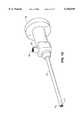
- FIG. 1Ais a side view of the transurethral resectoscope with an optical fiber.
- FIG. 1Bis a cross-sectional end view of the transurethral resectoscope with an optical fiber.
- FIG. 1Cis a side view of the transurethral resectoscope with an electrosurgical device.
- FIG. 1Dis a perspective view of the telescope used with the transurethral resectoscope.
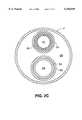
- FIG. 2Ais a side view of the transurethral morcellation scope of the present invention.
- FIG. 2Cis a cross-sectional end view of the transurethral morcellation scope of the present invention.
- FIG. 3Ais a perspective view of the morcellation probe of the present invention.
- FIG. 3Bis a cross-sectional view of the morcellation probe of the present invention.
- FIG. 4Ais a top view of the distal end of the outer tube for the morcellation probe.
- FIG. 4Bis a top view of the distal end of the inner tube for the morcellation probe.
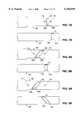
- FIGS. 5A-5Care side cross-sectional views of the morcellation probe distal end, illustrating the different positions of the reciprocating inner tube.
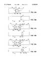
- FIGS. 6A-6Care side cross-sectional views of the morcellation probe distal end, illustrating the cutting action of the inner and outer tubes.
- FIGS. 7A/Bare top views of an alternate embodiment of the morcellation probe of the present invention.
- FIGS. 8A/Bare top views of a second alternate embodiment of the morcellation probe of the present invention.
- FIGS. 9A/Bare top views of a third alternate embodiment of the morcellation probe of the present invention.
- FIGS. 10A/Bare top views of a fourth alternate embodiment of the morcellation probe of the present invention.
- FIGS. 11A/Bare top views of a fifth alternate embodiment of the morcellation probe of the present invention.
- FIGS. 12A/Bare top views of a sixth alternate embodiment of the morcellation probe of the present invention.
- FIGS. 13A/Bare top views of a seventh alternate embodiment of the morcellation probe of the present invention.
- FIGS. 14A/Bare top views of a eighth alternate embodiment of the morcellation probe of the present invention.
- FIGS. 15A/Bare top views of a ninth alternate embodiment of the morcellation probe of the present invention.
- FIGS. 16A/Bare top views of a tenth alternate embodiment of the morcellation probe of the present invention.
- FIGS. 17A/Bare top views of a eleventh alternate embodiment of the morcellation probe of the present invention.
- FIGS. 18A/Bare top views of a twelfth alternate embodiment of the morcellation probe of the present invention.
- FIGS. 19A/Bare top views of a thirteenth alternate embodiment of the morcellation probe of the present invention.
- FIGS. 20A/Bare top views of a rotating morcellation probe embodiment of the present invention.
- FIGS. 21A/Bare top views of an auger type morcellation probe embodiment of the present invention.
- FIGS. 22A-22Dare side cross-sectional views of a fourteenth alternate embodiment of the present invention.
- the present inventionis a method and apparatus for transurethral resection of the prostate, which includes incising off pieces of targeted prostatic tissue, and morcellating the excised pieces of prostatic tissue for aspiration out of the patient.
- the incising stepis performed using optical energy delivered by a transurethral resectoscope 1 as shown in FIGS. 1A and 1B.
- Resectoscope 1includes an inner sheath 2 surrounded by an outer sheath 4, with an aspiration channel 6 formed therebetween.
- a port 8is located at the proximate end 5 of outer sheath 4, and is connected to an aspiration line 10 that connects to a vacuum source 26.
- the vacuum source 26is a mechanical pump capable of creating a variable vacuum, and with a tissue trap 30 to collect tissue and fluids aspirated from the patient.
- the vacuum source 26is a gravity drainage system that can provide a variable vacuum based upon its height below the resectoscope 1.
- Inner sheath 2forms an irrigation channel 28 therein that terminates with irrigation port 25.
- Irrigation line 24connects to port 25 to an irrigation source 12, which provides suitable irrigation fluid through irrigation line 24, channel 28, and out the delivery end 13 of the outer sheath 4.
- the proximate end 3 of inner sheath 2attaches to and forms a seal with proximate end 5 of outer sheath 4.
- a telescope 14includes a viewing channel 17 surrounded by a plurality of optical fibers 19, as best illustrated in FIG. 1D.
- the telescope 14inserts through proximate end 3 and extends along the inside length of the inner sheath 2.
- the proximate end of telescope 14includes an eyepiece 16 for viewing down the viewing channel 17, and an illumination port 18.
- the optical fibers 19extend from illumination port 18, down the outside of viewing channel 17 and terminate at the distal end of telescope 14.
- a light source(not shown) connects to the illumination port 18 to illuminate the area beyond the distal end of telescope 14 via the optical fibers 19.
- An optical fiber 20is attached at one end to laser system 22.
- the fiber 20extends through a input port 21, along the inside length of the inner sheath 2, and out the delivery end 13 of outer sheath 4.
- the delivery end 23 of optical fiber 20can direct the laser energy out longitudinally (end firing fiber) or laterally (side firing fiber).
- the optical fiber 20can be held in place by a wire loop, metal strap, or any equivalent thereof attached near the end, or along the length, of inner sheath 2.
- the laser system 22can be any laser system operating with a wavelength between approximately 200 nm and 3.0 um.
- laser system 22is a holmium laser that operates at 2.1 um, with 2-2.8 joules per pulse running at 25 Hz or higher.
- laser system 22could be an erbium laser system operating at 2.94 or 2.71 um, or an Nd:Yag laser operating at 1064 mn, or a doubled Nd:Yag laser system using, for example, a KTP doubling configuration operating at 532 nm.
- the resectoscope 1is inserted through the patient's urethra until the delivery end 13 is adjacent the targeted prostatic tissue.
- the irrigation source 12 and vacuum source 26are activated to provide irrigation and aspiration (suction) at the delivery end 13.
- irrigation and aspirationmaintains a clean environment for the procedure, and a clear field of view for the surgeon.
- the surgeonviewing through the eyepiece 16, positions the delivery end 23 of fiber 20 adjacent the tissue to be incised. Feeding the fiber 20 through input port 21 extends the delivery end 23 of fiber 20 further away from the delivery end 13 of outer sheath 4.
- the laser system 22is activated and the targeted prostatic tissue is incised using the optical energy exiting the optical fiber 20.
- the targeted prostatic tissuecan be incised and separated from the surgical capsule either in its entirety, or in relatively large pieces. It is preferable to incise the targeted prostatic tissue off in its entirety to minimize the number of incisions made during the procedure. Further, by making one continuous incision along the capsule (wall of the prostate), it is much easier to visualize and incise along the margin between the prostatic tissue to be resected and the capsule wall.
- the excised pieces of prostatic tissueare then pushed into the bladder either by the irrigation fluid exiting the distal end of inner sheath 2, or by manually pushing the tissue with delivery end 13 of outer sheath 4. It is preferable to position the excised pieces of prostatic tissue in the bladder so that morcellation removal of this tissue can be performed in the relatively large and safe space of the bladder, to minimize the risk of damaging adjacent tissue.
- an electrosurgical device 110can be used with resectoscope 1 as the incisional device to incise the targeted prostate tissue, as illustrated in FIG. 1C, instead of using optical fiber 20 and laser system 22.
- the electrosurgical device 110includes two leads 112 connected together at their distal ends with an electrosurgical cutting loop 114.
- the leads 112extend through the input port 21, along the inside length of the inner sheath 2, and out the delivery end 13 of outer sheath 4 (the same path as optical fiber 20 in the embodiment of FIGS. 1A/B).
- the proximate ends of leads 112are connected to a power source 116, for passing electrical current through leads 112.
- Handle assembly 118through which leads 112 pass, slides along telescope 14.
- handle assembly 118 and handle 120By grasping handle assembly 118 and handle 120 (attached to proximate end 3 of inner sheath 2), the leads 112 are fed through port 21 to retract and project loop 114 in and out relative to delivery end 13 of outer sheath 4.
- the power source 116When the power source 116 is activated, electrical current passes through leads 112 and loop 114, which then becomes an efficient cutting tool for incising the targeted prostatic tissue.
- the electrically energized loop 114is used to incise off large pieces of the targeted prostatic tissue.
- the resectoscope 1is replaced with, or reconfigured into, the morcellation scope 50 illustrated in FIGS. 2A-2C.
- Morcellation scope 50includes the same outer sheath 4, port 8, line 24, irrigation source 12, vacuum source 26, line 10 and telescope 14 as the resectoscope 1. However, line 24 from irrigation source 24 is connected to port 8, and thus aspiration channel 6 of resectoscope 1 becomes irrigation channel 29 inside outer sheath 4.
- Morcellation scope 50also includes a morcellation probe 52, as illustrated in FIGS. 3A-3B, having a motor assembly 58, and an inner tube 54 slidably disposed inside an outer tube 56. Tubes 54/56 extend inside and along the length of outer sheath 4. The proximate end of outer tube 56 mounts to the motor assembly 58 via a threaded locking nut 59 that engages a bushing 63 attached to the outer tube 56.
- the inner tube 54extends through motor assembly 58, with the proximate end thereof protruding out the back side of motor assembly 58 with a downward bend to allow clearance for the eyepiece 16.
- Aspiration line 24 from vacuum source 26connects to the proximate end of the inner tube 54.
- Inner tube 54defines an aspiration channel 64 therein.
- the distal end 55 of inner tube 54, and the distal end 57 of outer tube 56,extend out the delivery end 13 of the outer sheath 4.
- the telescope 14inserts through a telescope guide channel 61 in the motor assembly 58, and extends through outer sheath 4 parallel to inner/outer tubes 54/56.
- a seal 62attaches to the proximate end 5 of outer sheath 4 and forms a seal around telescope 14 and outer tube 56 to prevent irrigation fluid from leaking therefrom.
- seal 62fixably clamps telescope 14 to outer sheath 4, while allowing outer tube 56 to slide freely relative to outer sheath 4.
- the motor assembly 58is then freely slidable along telescope 14 between the illumination port 18 and proximate end 5 of outer sheath 4. Sliding the motor assembly 58 along the telescope 14 extends and retracts the distal end 57 of outer tube 56 relative to the delivery end 13 of outer sheath 4.
- the motor assembly 58includes a motor 60 that rotates a cam 90, which in turn drives a cam lever 92 in a reciprocating motion, as best illustrated in FIG. 3B.
- the cam lever 92is engaged with a pin 94, which engages with a bushing 96 that is attached to the inner tube 54.
- Rotation of the cam 90 by motor 60drives the inner tube 54 in a reciprocating motion within outer tube 56.
- Pin 94can be disengaged from bushing 96 by movement of push button 98, which pushes down on end-flange 100 of pin 94. Once pin 94 is disengaged from bushing 96, inner tube 54 can be removed from the motor assembly 58 and the outer tube 56 (i.e. for replacement, sterilization, etc).
- FIGS. 4A and 4BThe distal ends 55/57 of inner/outer tube 54/56 are illustrated in FIGS. 4A and 4B.
- An aperture 66is formed adjacent the distal end 57 of outer tube 56, with cutting edges 68a and 68b. Ports 70 are formed adjacent to the cutting edges 68a/b.
- An aperture 72is formed adjacent the distal end 55 of inner tube 54, with cutting edges 74a and 74b.
- the inner tube 54travels between three positions: a retracted position (FIG. 5A), a medial position (FIG. 5B), and an extended position (FIG. 5C).
- a retracted position(FIG. 5A)
- a medial position(FIG. 5B)
- an extended position(FIG. 5C)
- the apertures 66 and 72fully overlap each other, thus providing direct access to the aspiration channel 64.
- the inner tube 54seals aperture 66 and one of the ports 70, while providing access to aspiration channel 64 through the other of the ports 70.
- the diameter of the outer tube 56is tapered down in diameter near distal end 57, as shown in FIG. 4A. Tapering down outer tube 56 isolates and reduces the running friction between the outer tube 56 and inner tube 54 and achieves a tight, small diametrical tolerance between the inner and outer tube 54/56 adjacent the tube ends 55/57, which enhances the cutting action of the reciprocating motion between these tubes.
- fabrication costsare reduced, the device is less sensitive to slightly bent or deflected tubes 54/56, and binding of inner tube 54 inside outer tube 56 is prevented.
- a control box 75connected to a footswitch 76, operates the vacuum source 26 and motor 60. Slightly depressing the footswitch 76 activates the vacuum source 24 to create a low level aspiration action (suction) through apertures 66/72 and ports 70. Depressing the footswitch further increases the vacuum from source 24, and thereby increases the aspiration action through apertures 66/72 and ports 70. Further depression of the footswitch causes the motor 60 to activate and drive the inner tube 54 in the reciprocation motion at a predetermined rate relative to the outer tube 56. Gradually increasing the depression of footswitch 76 results in a gradual increase in the vacuum from source 24 and/or the speed of reciprocation of the inner tube 54 by motor 60.
- the control box 75can be set to provide the desired combination of suction and motor speed at various positions of the footswitch 76.
- the morcellation procedure of the present inventive methodis carried out by inserting the morcellation scope 50 through the urethra until the delivery end 13 is positioned in the bladder.
- the irrigation source 12is then activated.
- the surgeonviewing through the eyepiece 16, locates a piece of prostatic tissue that had previously been deposited in the bladder.
- the vacuum source 26By activating the vacuum source 26 at a low vacuum setting with footswitch 76 and positioning the distal end 57 of outer tube 56 adjacent the targeted piece of prostate, the low level aspiration action of the probe draws the tissue to, and attaches the tissue against, the apertures 66/72 and ports 70.
- the surgeonthen re-positions the distal end 57 of outer probe 56, with the target tissue attached thereto, toward the center of the bladder, where it is safe to operate the morcellation probe without damaging surrounding tissue.
- the surgeondepresses the footswitch 76 further until motor 60 is activated at the desired speed.
- the reciprocating action of inner tube 54 together with the aspiration from the vacuum source 26efficiently morcellates the targeted prostatic tissue (cuts the tissue into very small pieces), and aspirates the targeted tissue from the patient.
- the apertures 66/72become misaligned (for example during movement from the medial position to the extended position)
- the small portion of tissue 102 drawn into the apertures 66/72is cut by the approaching cutting edges 74a and 68b, and aspirated out of the patient via the aspiration channel 64 and aspiration line 24.
- the ports 70function to manipulate the targeted tissue position by maintaining continuous aspiration adjacent aperture 66.
- the continuous aspirationprevents the targeted tissue mass 102 from disengaging from aperture 66 so that upon reverse reciprocal motion of inner tube 54, another portion of the tissue mass 102 will be drawn through apertures 68/72 for cutting/aspiration using cutting edges 74b and 68a.
- the surgeonneed only maintain the position of the distal end 57 of tube 56 away from the bladder walls and allow the morcellation probe 52 to efficiently and quickly morcellate the target tissue 102 bit by bit until fully morcellated and aspirated out of the patient. Once the tissue is fully aspirated out of the patient, the footswitch is released to cease the reciprocation motion of inner tube 54 and to lower the aspiration to a safe level, so that the next piece of excised prostatic tissue can be retrieved and morcellated.
- cutting edges 74a and 74balternately pass and seal ports 70 at different times.
- This cutting and sealing action at ports 70serves an important self cleaning function, so that any tissue or debris that may clog the ports 70 is cut and aspirated, or released. If one of ports 70 becomes clogged, then continuous aspiration may be lost, which could result in disengagement of the target tissue 102 from the probe 52, thus reducing morcellation efficiency.
- outer sheath 4is inserted into the urethra only once during the prostate resection procedure. Therefore, resectoscope 1 can be reconfigured to morcellation scope 50 without removing outer sheath 4 from the patient.
- the inner sheath 2(containing the telescope 14 and either the optical fiber 20 or electrosurgical leads 112 and loop 114) is detached from, and slid rearwardly out of, outer sheath 4.
- the telescope 14is removed from inner sheath 2 and inserted through telescope guide channel 61 in the motor assembly 58.
- the aspiration lineis detached from port 8 and attached to the proximate end of inner tube 54.
- the irrigation lineis detached from port 25 and attached to port 8.
- Seal 62is then placed over the telescope 14 and outer tube 56. Telescope 14 and outer tube 56 are inserted into the outer sheath 4, whereby seal 62 is affixed to the proximate end 5 of outer sheath 4 for sealing the telescope 14 and outer tube 56 in place.
- the aspiration apertures 66 and 72, and ports 70can have various shapes and configurations. For maximum morcellation efficiency, these various shapes and configurations should maintain the continuous aspiration adjacent aperture 66 throughout the reciprocating motion of the inner tube 54, while incorporating the self-cleaning feature of closing off any apertures or ports in the outer tube 56 at least once during the reciprocating cycle.
- FIGS. 7A and 7Billustrate slots 78 formed continuously with aperture 66, for providing continuous aspiration.
- the cutting edges 68a/b of aperture 66can be angled relative to cutting edges 74a/b as shown in FIGS.
- the cutting edges 74a/bcan be angled in the opposite direction as the angled cutting edges 68a/b of aperture 66 as shown in FIGS. 9A and 9B.
- Apertures 66/72can instead be circular shaped, as shown in FIGS. 10A/B.
- a second aperture 66 or 72can be formed on outer/inner tubes 56/54, as shown in FIGS. 11A/B, 12A/B, 14A/B and 15A/B, to increase the cutting action per cycle. If multiple apertures formed on the same inner or outer tube 54/56 are close enough together, and the travel of inner tube 54 is limited to maintain continuous aspiration, ports 70 can be eliminated (i.e. FIGS. 11A/B).
- the shape and numbers of apertures 66 and 72, and ports 70, formed on outer/inner tubes 56/54can be varied to achieve the desired cutting action, as illustrated in FIGS. 13A/B, 14A/B, 15A/B, 16A/B and 17A/B.
- the cutting edgescan be non-linear (FIGS. 10A/B, 13A, 14A, and 15A/B) or irregularly shaped (FIG. 17A) to provide varying cutting angles between the cutting edges 68a and 74b, and/or between 68b and 74a, during one or both cutting actions per reciprocation cycle of inner tube 54.
- additional ports 70can be added to inner/outer tubes 54/56, as illustrated in FIGS. 18A/B. These additional ports 70 should be located away from aperture 66, for example on the opposing underneath side of inner/outer tubes 54/56, such that they do not manipulate the targeted tissue. The additional ports 70 will supply additional fluid to the aspiration channel 64 when in a fluid environment to prevent blockage thereof without manipulating the targeted tissue being morcellated by apertures 66/72. These additional ports 70 should be sealed at least once per reciprocation cycle to prevent clogging thereof.
- any or all apertures and ports shown on outer tube 56can instead be formed on inner tube 54, and vice versa (i.e. one or both ports 70 in FIGS. 4A/B etc. can be formed on inner tube 54 instead of outer tube 56, or apertures 66 of FIG. 15A can be formed on inner tube 54 and aperture 72 of FIG. 15B can be formed on outer tube 56, etc.).
- part or all of the aperture/port pattern of inner tube 54 in one figurecan be used with part or all of the aperture/port pattern of outer tube 56 in other figure (i.e. inner tube 54 of FIG.
- FIGS. 7A/Bcould be formed on a top side of inner/outer tubes 54/56
- FIGS. 8A/Bcould be formed on an opposing bottom side of the inner/outer tubes 54/56.
- morcellation probe 52has been described above as longitudinally reciprocating the inner tube 54 relative to the outer tube 56
- the scope of the present inventionalso includes using a rotating morcellator, where inner tube 54 spins about its longitudinal axis relative to outer tube 56.
- the aperture/port patterns illustrated in FIGS. 4A/B and 7A/B-19A/Bare formed around tubes 54/56 instead of along the longitudinal length of tubes 54/56 (i.e. the patterns are rotated 90°).
- FIGS. 20A/Billustrate the 90° reorientation of the aperture/ports patterns shown in FIGS. 4A/B.
- tissue drawn into the apertures 66/72is cut by the approaching cutting edges 68a and 74b, and cutting edges 68b and 74a.
- Motor 60rotates inner tube 54 about its longitudinal axis either continuously in one direction, or in an oscillating fashion.
- the aperture/port patternscan be formed all the way around the inner/outer tubes 54/56. If the inner tube 54 rotationally oscillates, then constant aspiration is achieved by rotating between two rotational positions in the same manner as longitudinally reciprocating between the two extended/retracted positions as described above.
- FIGS. 21A/Billustrate another embodiment of the present invention: an auger type morcellation probe 52.
- Outer tube 56has an aperture 66 with cutting edges 122.
- a spiral shaped groove 124is formed on the outer surface of inner tube 54, either along its entire length or preferably on just a portion near its distal end.
- the spiral shaped groove 124forms a continuous cutting edge 126 for cutting tissue against cutting edges 122 of aperture 66.
- One or more aspiration ports 128are formed in groove 124 (preferably at the bottom of groove 124) and are continuous with aspiration channel 64.
- Fluid ports 130can be formed in outer tube 56, located away from aperture 66 (i.e.
- tissue drawn into aperture 66is cut by cutting edge 126 passing beyond cutting edges 122.
- the cut tissueis drawn along groove 124, through aspiration ports 128, and out through aspiration channel 64. Continuous aspiration through aperture 66 is preserved because at least some portion of groove 124 is exposed to aperture 66 at all times.
- Aperture 66can have any of the aperture/ports shapes illustrated in FIGS. 7A/B-20A/B.
- inner tubecan have no ports 128 (and even be a solid tube with no aspiration channel 64 therein).
- the vacuum sourceis attached to the motor assembly 58 or outer tube 56 to provide a vacuum between inner tube 54 and outer tube 56, whereby the cut tissue is aspirated by being drawn along groove 124, between inner and outer tubes 54/56, and out to the vacuum source 26.
- FIGS. 22A-22Dillustrate one last embodiment of the present invention.
- the distal ends of inner/outer tubes 54/56are the same as illustrated in FIGS. 5A-5C, except that there are no aspiration ports 70, and the distal end 57 of outer tube 56 is open instead of closed to form a cutting edge.
- the distal end 55 of the inner tube 54travels out through the open distal end 57 of the outer tube 56 to provide three cutting actions per cycle instead of two.
- FIG. 22Aillustrates the first cutting action where cutting edges 74a and 68b pass each other as the inner tube 54 travels toward the open distal end 57 of outer tube 56.
- FIG. 22Billustrates the distal end 55 of inner tube 54 protruding from the open distal end 57 of outer tube 56.
- FIG. 22Cillustrates the second cutting action where cutting edge 74b and distal end 57 pass each other as the inner tube 54 retracts back inside of outer tube 56.
- FIG. 22Dillustrates the third cutting action where cutting edges 74b and 68a pass each other as the inner tube 54 further retracts into outer tube 56.
- This last embodimenthas the advantage of providing three cutting actions instead of two per reciprocating cycle. During each cutting action, tissue is drawn into aperture 72, after which cutting edges sever the tissue so that it can be aspirated out of the patient via the aspiration channel 64 and aspiration line 24. With the additional cutting action (total of three) per reciprocating cycle, in most cases the tissue is properly held in place without the need for aspiration ports.
- the present inventionis not limited to the embodiments described above and illustrated herein, but encompasses any and all variations falling within the scope of the appended claims.
- the surgeonmay wish to morcellate some of the excised prostatic tissue while still positioned in the urethra, without pushing the excised prostatic tissue into the bladder.
- 22A-22Dcan have shaped apertures 66/72, and the amount of movement of inner tube 54 can be reduced to eliminate the third cutting action between cutting edges 74b and 68a in an effort to selectively reduce the overall cutting action of the morcellating probe per reciprocating cycle.
Landscapes
- Health & Medical Sciences (AREA)
- Life Sciences & Earth Sciences (AREA)
- Surgery (AREA)
- Animal Behavior & Ethology (AREA)
- Public Health (AREA)
- Engineering & Computer Science (AREA)
- Biomedical Technology (AREA)
- Heart & Thoracic Surgery (AREA)
- Medical Informatics (AREA)
- Molecular Biology (AREA)
- Veterinary Medicine (AREA)
- General Health & Medical Sciences (AREA)
- Nuclear Medicine, Radiotherapy & Molecular Imaging (AREA)
- Orthopedic Medicine & Surgery (AREA)
- Physics & Mathematics (AREA)
- Biophysics (AREA)
- Optics & Photonics (AREA)
- Pathology (AREA)
- Radiology & Medical Imaging (AREA)
- Surgical Instruments (AREA)
Abstract
Description
Claims (29)
Priority Applications (2)
| Application Number | Priority Date | Filing Date | Title |
|---|---|---|---|
| US09/248,739US6156049A (en) | 1997-04-11 | 1999-02-10 | Method and apparatus for transurethral resection of the prostate |
| PCT/US2000/002667WO2000047116A1 (en) | 1999-02-10 | 2000-02-02 | Method and apparatus for transurethral resection of the prostate |
Applications Claiming Priority (2)
| Application Number | Priority Date | Filing Date | Title |
|---|---|---|---|
| US08/837,003US6024751A (en) | 1997-04-11 | 1997-04-11 | Method and apparatus for transurethral resection of the prostate |
| US09/248,739US6156049A (en) | 1997-04-11 | 1999-02-10 | Method and apparatus for transurethral resection of the prostate |
Related Parent Applications (1)
| Application Number | Title | Priority Date | Filing Date |
|---|---|---|---|
| US08/837,003Continuation-In-PartUS6024751A (en) | 1997-04-11 | 1997-04-11 | Method and apparatus for transurethral resection of the prostate |
Publications (1)
| Publication Number | Publication Date |
|---|---|
| US6156049Atrue US6156049A (en) | 2000-12-05 |
Family
ID=22940466
Family Applications (1)
| Application Number | Title | Priority Date | Filing Date |
|---|---|---|---|
| US09/248,739Expired - LifetimeUS6156049A (en) | 1997-04-11 | 1999-02-10 | Method and apparatus for transurethral resection of the prostate |
Country Status (2)
| Country | Link |
|---|---|
| US (1) | US6156049A (en) |
| WO (1) | WO2000047116A1 (en) |
Cited By (123)
| Publication number | Priority date | Publication date | Assignee | Title |
|---|---|---|---|---|
| WO2003050231A1 (en)* | 2001-12-13 | 2003-06-19 | Pi-Yao Aileen Liu | Pipette apparatus |
| WO2005104966A1 (en)* | 2004-04-30 | 2005-11-10 | Karl Storz Gmbh & Co. Kg | Surgical instrument system |
| US20050261677A1 (en)* | 2004-05-20 | 2005-11-24 | Gyrus Medical Limited | Surgical instrument |
| US6997926B2 (en) | 2002-02-04 | 2006-02-14 | Boston Scientific Scimed, Inc. | Resistance heated tissue morcellation |
| US20060047185A1 (en)* | 2004-08-27 | 2006-03-02 | Cemal Shener | Tissue resecting system |
| US20060129159A1 (en)* | 2002-06-29 | 2006-06-15 | Hee-Young Lee | Facial bone contouring device using hollowed rasp provided with non-plugging holes formed through cutting plane |
| US20060161189A1 (en)* | 2002-09-27 | 2006-07-20 | Harp Richard J | Surgical file system with a visualization instrument |
| US20060253069A1 (en)* | 2005-05-09 | 2006-11-09 | Jamie Li | Method and device for tissue removal and for delivery of a therapeutic agent or bulking agent |
| US20060251697A1 (en)* | 2005-05-09 | 2006-11-09 | Jamie Li | Injectable bulking compositions |
| US7150713B2 (en) | 2003-10-16 | 2006-12-19 | Smith & Nephew, Inc. | Endoscopic device |
| US7249602B1 (en)* | 1997-09-04 | 2007-07-31 | Smith & Nephew, Inc. | Surgical endoscopic cutting device and method for its use |
| US20080065129A1 (en)* | 2006-09-07 | 2008-03-13 | Gyrus Medical Limited | Tissue morcellating device |
| US20080065021A1 (en)* | 2006-09-07 | 2008-03-13 | Gyrus Medical Limited | Surgical instrument |
| EP1911391A1 (en)* | 2006-10-11 | 2008-04-16 | Alka Kumar | System for evacuating detached tissue in continuous flow irrigation endoscopic procedures |
| EP1911390A1 (en)* | 2006-10-11 | 2008-04-16 | Alka Kumar | Efficient continuous flow irrigation endoscope |
| US20080103412A1 (en)* | 2006-11-01 | 2008-05-01 | Yem Chin | Removing Tissue |
| US20090124975A1 (en)* | 2007-11-12 | 2009-05-14 | Oliver Dana A | Systems and methods for surgical removal of brain tumors |
| US20090270894A1 (en)* | 2008-04-25 | 2009-10-29 | Joshua David Rubin | Surgical instrument with internal irrigation |
| US20090270791A1 (en)* | 2008-04-28 | 2009-10-29 | Urotech, Inc. | Benign prostatic hyperplasia surgical system featuring mechanical coring probe with live aspiration |
| EP2218412A1 (en) | 2009-02-16 | 2010-08-18 | Karl Storz GmbH & Co. KG | Medical instrument for cutting tissue |
| US7862552B2 (en) | 2005-05-09 | 2011-01-04 | Boston Scientific Scimed, Inc. | Medical devices for treating urological and uterine conditions |
| KR101014958B1 (en) | 2008-06-12 | 2011-02-15 | 전북대학교산학협력단 | Prostate Surgery Device |
| US20110208087A1 (en)* | 2010-02-22 | 2011-08-25 | Trezza Ii Michael J | Tissue Harvesting, Mincing, and Transport Device |
| US20110230904A1 (en)* | 2001-10-26 | 2011-09-22 | Smith & Nephew, Inc. | Reciprocating rotary arthroscopic surgical instrument |
| US8080011B2 (en) | 2002-09-27 | 2011-12-20 | Surgitech, L.L.C. | Reciprocating cutting tool |
| US20120022329A1 (en)* | 2009-04-01 | 2012-01-26 | Wagh Mihir S | Apparatuses for advancing an endoscope through a passage |
| US8152820B2 (en) | 2008-06-26 | 2012-04-10 | Dai-Z, Llc | Medical device and method for human tissue and foreign body extraction |
| US8328792B2 (en) | 2005-10-27 | 2012-12-11 | C. R. Bard, Inc. | Enhanced pre-wetted intermittent catheter with lubricious coating |
| US20130211439A1 (en)* | 2010-11-05 | 2013-08-15 | Volker Geuder | Apparatus for cutting and aspirating tissue |
| US20140039344A1 (en)* | 2003-02-24 | 2014-02-06 | Senorx, Inc. | Biopsy device with inner cutting member |
| US20140352358A1 (en)* | 2013-06-04 | 2014-12-04 | Coherent, Inc. | Laser-scribing of chemically strengthened glass |
| US8961551B2 (en) | 2006-12-22 | 2015-02-24 | The Spectranetics Corporation | Retractable separating systems and methods |
| US8998882B2 (en) | 2013-03-13 | 2015-04-07 | C. R. Bard, Inc. | Enhanced pre-wetted intermittent catheter with lubricious coating |
| US9028520B2 (en) | 2006-12-22 | 2015-05-12 | The Spectranetics Corporation | Tissue separating systems and methods |
| US9033149B2 (en) | 2010-03-04 | 2015-05-19 | C. R. Bard, Inc. | Catheter assembly/package utilizing a hydrating/hydrogel sleeve and a foil outer layer and method of making and using the same |
| US20150282817A1 (en)* | 2010-04-12 | 2015-10-08 | K2M, Inc. | Expandable reamer and method of use |
| US9155454B2 (en) | 2010-09-28 | 2015-10-13 | Smith & Nephew, Inc. | Hysteroscopic system |
| DE102014206976A1 (en)* | 2014-04-10 | 2015-10-15 | OLYMPUS Winter & lbe GmbH | Electrosurgical instrument and method for inserting an applicator into body lumens |
| US20150335348A1 (en)* | 2013-01-07 | 2015-11-26 | Taryag Medical Ltd. | Expandable atherectomy device |
| US9283040B2 (en) | 2013-03-13 | 2016-03-15 | The Spectranetics Corporation | Device and method of ablative cutting with helical tip |
| US9291663B2 (en) | 2013-03-13 | 2016-03-22 | The Spectranetics Corporation | Alarm for lead insulation abnormality |
| US9413896B2 (en) | 2012-09-14 | 2016-08-09 | The Spectranetics Corporation | Tissue slitting methods and systems |
| USD765243S1 (en) | 2015-02-20 | 2016-08-30 | The Spectranetics Corporation | Medical device handle |
| US20160270813A1 (en)* | 2015-03-20 | 2016-09-22 | Terumo Kabushiki Kaisha | Catheter system and treatment method |
| US9456872B2 (en) | 2013-03-13 | 2016-10-04 | The Spectranetics Corporation | Laser ablation catheter |
| USD770616S1 (en) | 2015-02-20 | 2016-11-01 | The Spectranetics Corporation | Medical device handle |
| US9603618B2 (en) | 2013-03-15 | 2017-03-28 | The Spectranetics Corporation | Medical device for removing an implanted object |
| US9615969B2 (en) | 2012-12-18 | 2017-04-11 | Novartis Ag | Multi-port vitrectomy probe with dual cutting edges |
| US9668765B2 (en) | 2013-03-15 | 2017-06-06 | The Spectranetics Corporation | Retractable blade for lead removal device |
| US20170172602A1 (en)* | 2015-12-21 | 2017-06-22 | Boston Scientific Scimed, Inc. | Medical device and methods of use |
| US9693898B2 (en) | 2014-11-19 | 2017-07-04 | Novartis Ag | Double-acting vitreous probe with contoured port |
| US9821139B2 (en) | 2009-08-13 | 2017-11-21 | C. R. Bard, Inc. | Catheter having internal hydrating fluid storage and/or catheter package using the same and method of making and/or using the same |
| US20170340192A1 (en)* | 2016-05-26 | 2017-11-30 | Covidien Lp | Continuous flow endoscope |
| US9883885B2 (en) | 2013-03-13 | 2018-02-06 | The Spectranetics Corporation | System and method of ablative cutting and pulsed vacuum aspiration |
| US9925366B2 (en) | 2013-03-15 | 2018-03-27 | The Spectranetics Corporation | Surgical instrument for removing an implanted object |
| US9980743B2 (en) | 2013-03-15 | 2018-05-29 | The Spectranetics Corporation | Medical device for removing an implanted object using laser cut hypotubes |
| WO2018109783A1 (en)* | 2016-12-14 | 2018-06-21 | Xcellance Medical Technologies Pvt.Ltd | Instrument with a detachable motor drive assembly, telescope and cutter tube assembly |
| US10105132B2 (en) | 2005-05-20 | 2018-10-23 | Neotract, Inc. | Devices, systems and methods for treating benign prostatic hyperplasia and other conditions |
| US10130353B2 (en) | 2012-06-29 | 2018-11-20 | Neotract, Inc. | Flexible system for delivering an anchor |
| US10136913B2 (en) | 2013-03-15 | 2018-11-27 | The Spectranetics Corporation | Multiple configuration surgical cutting device |
| US10143461B2 (en) | 2005-05-20 | 2018-12-04 | Neotract, Inc. | Devices, systems and methods for retracting, lifting, compressing, supporting or repositioning tissues or anatomical structures |
| US10149961B2 (en) | 2009-07-29 | 2018-12-11 | C. R. Bard, Inc. | Catheter having improved drainage and/or a retractable sleeve and method of using the same |
| US10195014B2 (en) | 2005-05-20 | 2019-02-05 | Neotract, Inc. | Devices, systems and methods for treating benign prostatic hyperplasia and other conditions |
| US10265061B2 (en) | 2005-05-20 | 2019-04-23 | Neotract, Inc. | Latching anchor device |
| US10292801B2 (en) | 2012-03-29 | 2019-05-21 | Neotract, Inc. | System for delivering anchors for treating incontinence |
| US10299803B2 (en) | 2016-08-04 | 2019-05-28 | Covidien Lp | Self-aligning drive coupler |
| US10299780B2 (en) | 2005-05-20 | 2019-05-28 | Neotract, Inc. | Apparatus and method for manipulating or retracting tissue and anatomical structure |
| US10299819B2 (en) | 2016-07-28 | 2019-05-28 | Covidien Lp | Reciprocating rotary surgical cutting device and system for tissue resecting, and method for its use |
| US10383691B2 (en) | 2013-03-13 | 2019-08-20 | The Spectranetics Corporation | Last catheter with helical internal lumen |
| US10405924B2 (en) | 2014-05-30 | 2019-09-10 | The Spectranetics Corporation | System and method of ablative cutting and vacuum aspiration through primary orifice and auxiliary side port |
| US10426509B2 (en) | 2005-05-20 | 2019-10-01 | Neotract, Inc. | Median lobe destruction apparatus and method |
| US10448999B2 (en) | 2013-03-15 | 2019-10-22 | The Spectranetics Corporation | Surgical instrument for removing an implanted object |
| US10492792B2 (en) | 2005-05-20 | 2019-12-03 | Neotract, Inc. | Devices, systems and methods for treating benign prostatic hyperplasia and other conditions |
| US10631889B2 (en) | 2014-12-16 | 2020-04-28 | Covidien Lp | Surgical device with incorporated tissue extraction |
| US10639197B2 (en) | 2017-06-19 | 2020-05-05 | Alcon Inc. | Vitrectomy probe |
| US10750931B2 (en) | 2015-05-26 | 2020-08-25 | Covidien Lp | Systems and methods for generating a fluid bearing for an operative procedure |
| JP2020131041A (en)* | 2019-02-22 | 2020-08-31 | ジャイラス・エーシーエムアイ・インコーポレーテッド | How to reciprocate in a surgical shaver |
| US10772652B2 (en) | 2015-01-28 | 2020-09-15 | Covidien Lp | Tissue resection system |
| US10772654B2 (en) | 2017-03-02 | 2020-09-15 | Covidien Lp | Fluid-driven tissue resecting instruments, systems, and methods |
| US10804769B2 (en) | 2015-06-17 | 2020-10-13 | Covidien Lp | Surgical instrument with phase change cooling |
| US10799264B2 (en) | 2015-06-18 | 2020-10-13 | Covidien Lp | Surgical instrument with suction control |
| US10835279B2 (en) | 2013-03-14 | 2020-11-17 | Spectranetics Llc | Distal end supported tissue slitting apparatus |
| US10842532B2 (en) | 2013-03-15 | 2020-11-24 | Spectranetics Llc | Medical device for removing an implanted object |
| US10842350B2 (en) | 2015-06-17 | 2020-11-24 | Covidien Lp | Endoscopic device with drip flange and methods of use thereof for an operative procedure |
| US10869684B2 (en) | 2018-02-13 | 2020-12-22 | Covidien Lp | Powered tissue resecting device |
| US10898218B2 (en) | 2019-02-25 | 2021-01-26 | Covidien Lp | Tissue resecting device including a motor cooling assembly |
| US10912917B2 (en) | 2009-12-23 | 2021-02-09 | C. R. Bard, Inc. | Catheter assembly/package utilizing a hydrating/hydrogel sleeve and method of making and using the same |
| US10925587B2 (en) | 2005-05-20 | 2021-02-23 | Neotract, Inc. | Anchor delivery system |
| US10945752B2 (en) | 2019-03-20 | 2021-03-16 | Covidien Lp | Tissue resecting instrument including a rotation lock feature |
| US10987131B2 (en) | 2017-05-25 | 2021-04-27 | Coopersurgical, Inc. | Tissue containment systems and related methods |
| US11065147B2 (en) | 2018-10-18 | 2021-07-20 | Covidien Lp | Devices, systems, and methods for pre-heating fluid to be introduced into a patient during a surgical procedure |
| WO2021144602A1 (en) | 2020-01-17 | 2021-07-22 | Plascere | Lightweight powered handpiece for a liposuction device and medical device comprising same |
| US11083481B2 (en) | 2019-02-22 | 2021-08-10 | Covidien Lp | Tissue resecting instrument including an outflow control seal |
| US11141182B2 (en) | 2019-03-01 | 2021-10-12 | Gyrus Acmi, Inc. | Methods of reciprocation in a surgical shaver |
| US11147579B2 (en) | 2019-02-27 | 2021-10-19 | Gyrus Acmi. Inc. | Methods of reciprocation in a surgical shaver |
| US11154318B2 (en) | 2019-02-22 | 2021-10-26 | Covidien Lp | Tissue resecting instrument including an outflow control seal |
| US11179172B2 (en) | 2019-12-05 | 2021-11-23 | Covidien Lp | Tissue resecting instrument |
| US11197710B2 (en) | 2018-10-26 | 2021-12-14 | Covidien Lp | Tissue resecting device including a blade lock and release mechanism |
| US11213312B2 (en) | 2019-02-27 | 2022-01-04 | Gyrus Acmi, Inc. | Methods of reciprocation in a surgical shaver |
| US11234735B2 (en)* | 2019-05-20 | 2022-02-01 | Covidien Lp | Tissue resecting instrument including variable drive |
| US11241333B2 (en)* | 2014-03-20 | 2022-02-08 | Medical Instrument Development Laboratories, Inc. | Aspirating cutter and method to use |
| US11317947B2 (en) | 2020-02-18 | 2022-05-03 | Covidien Lp | Tissue resecting instrument |
| US11376032B2 (en) | 2019-12-05 | 2022-07-05 | Covidien Lp | Tissue resecting instrument |
| US20220240766A1 (en)* | 2021-02-03 | 2022-08-04 | Chin-Piao Chang | Endoscope Kit having Functions of Injection, Clamping and Placing Medical Materials or Medicines |
| US11452806B2 (en) | 2019-10-04 | 2022-09-27 | Covidien Lp | Outflow collection vessels, systems, and components thereof for hysteroscopic surgical procedures |
| US11517341B2 (en) | 2019-02-22 | 2022-12-06 | Gyrus ACMl, Inc. | Methods of reciprocation in a surgical shaver |
| US11547782B2 (en) | 2020-01-31 | 2023-01-10 | Covidien Lp | Fluid collecting sheaths for endoscopic devices and systems |
| US11547815B2 (en) | 2018-05-30 | 2023-01-10 | Covidien Lp | Systems and methods for measuring and controlling pressure within an internal body cavity |
| US11553977B2 (en) | 2019-05-29 | 2023-01-17 | Covidien Lp | Hysteroscopy systems and methods for managing patient fluid |
| US11571233B2 (en) | 2020-11-19 | 2023-02-07 | Covidien Lp | Tissue removal handpiece with integrated suction |
| US11589849B2 (en) | 2003-02-24 | 2023-02-28 | Senorx, Inc. | Biopsy device with selectable tissue receiving aperature orientation and site illumination |
| US11596429B2 (en) | 2020-04-20 | 2023-03-07 | Covidien Lp | Tissue resecting instrument |
| US11672520B2 (en) | 2017-12-23 | 2023-06-13 | Teleflex Life Sciences Limited | Expandable tissue engagement apparatus and method |
| RU2801272C1 (en)* | 2020-01-17 | 2023-08-04 | Пласере | Drive handle for a liposuction device and a medical device containing it |
| US11737777B2 (en) | 2020-02-05 | 2023-08-29 | Covidien Lp | Tissue resecting instruments |
| US11883058B2 (en) | 2019-03-26 | 2024-01-30 | Covidien Lp | Jaw members, end effector assemblies, and ultrasonic surgical instruments including the same |
| US11890237B2 (en) | 2019-10-04 | 2024-02-06 | Covidien Lp | Outflow collection vessels, systems, and components thereof for hysteroscopic surgical procedures |
| US12016626B2 (en)* | 2018-02-09 | 2024-06-25 | Gyrus Acmi, Inc. | Endoscope unclogging system and method |
| US12053203B2 (en) | 2014-03-03 | 2024-08-06 | Spectranetics, Llc | Multiple configuration surgical cutting device |
| CN118490440A (en)* | 2024-04-30 | 2024-08-16 | 思埃然医疗科技(苏州)有限公司 | Ophthalmic surgical probe device |
| US12156673B2 (en) | 2020-10-07 | 2024-12-03 | Covidien Lp | Temperature measurement device for a handpiece of a surgical instrument |
| US12303109B2 (en) | 2021-12-22 | 2025-05-20 | Covidien Lp | Surgical systems and methods for component cooling while warming fluid to be introduced during a surgical procedure |
| US12364500B2 (en) | 2021-05-26 | 2025-07-22 | Covidien Lp | Tissue resecting instrument |
Families Citing this family (5)
| Publication number | Priority date | Publication date | Assignee | Title |
|---|---|---|---|---|
| US7905896B2 (en) | 2004-03-04 | 2011-03-15 | Straub Medical Ag | Catheter for aspirating, fragmenting and removing material |
| CH699981A2 (en)* | 2008-11-27 | 2010-05-31 | Straub Medical Ag | Catheter for aspirating, fragmenting and out transport of removable material from blood vessels. |
| CH701695A1 (en)* | 2009-08-27 | 2011-02-28 | Straub Medical Ag | Catheter with protection system for aspirating, fragmenting and out pumping of removable material from hollow bodies or vessels, in particular of the human or animal body. |
| CN110448384B (en)* | 2019-07-31 | 2024-06-07 | 宝鸡市安元智能科技有限公司 | Clamping device for electrotome scalpel in transurethral prostatometry |
| CN112120788B (en)* | 2020-09-23 | 2021-11-26 | 安徽医科大学第一附属医院 | Small-caliber laser resectoscope |
Citations (32)
| Publication number | Priority date | Publication date | Assignee | Title |
|---|---|---|---|---|
| US3289669A (en)* | 1964-02-25 | 1966-12-06 | Donald J Dwyer | Biopsy capsule arrangement |
| GB1116465A (en)* | 1966-06-08 | 1968-06-06 | John Shipton | Colonic biopsy instrument |
| US4246902A (en)* | 1978-03-10 | 1981-01-27 | Miguel Martinez | Surgical cutting instrument |
| US4436097A (en)* | 1982-06-07 | 1984-03-13 | Cunningham Patrick J | Cardiovascular exercise apparatus |
| EP0185810A1 (en)* | 1984-12-14 | 1986-07-02 | Said Ismail Hakky | Resectoscope with automatic and manual operation |
| US4620547A (en)* | 1983-12-31 | 1986-11-04 | Richard Wolf Gmbh | Instrument for sampling tissue specimens |
| US4649919A (en)* | 1985-01-23 | 1987-03-17 | Precision Surgical Instruments, Inc. | Surgical instrument |
| US4657018A (en)* | 1983-08-19 | 1987-04-14 | Hakky Said I | Automatic/manual resectoscope |
| EP0310285A2 (en)* | 1987-09-30 | 1989-04-05 | BAXTER INTERNATIONAL INC. (a Delaware corporation) | Surgical cutting instrument with end and side openings |
| US4846192A (en)* | 1987-04-17 | 1989-07-11 | Eastman Kodak Company | Rearwardly acting surgical catheter |
| US4909782A (en)* | 1986-09-04 | 1990-03-20 | Wisap-Gesellschaft Fur Wissenschaftlichen Apparatebau Mbh | Tissue punch |
| US4955882A (en)* | 1988-03-30 | 1990-09-11 | Hakky Said I | Laser resectoscope with mechanical and laser cutting means |
| US5106364A (en)* | 1989-07-07 | 1992-04-21 | Kabushiki Kaisha Topcon | Surgical cutter |
| US5201731A (en)* | 1988-03-30 | 1993-04-13 | Hakky Said I | Laser resectoscope with ultransonic imaging means |
| US5242460A (en)* | 1990-10-25 | 1993-09-07 | Devices For Vascular Intervention, Inc. | Atherectomy catheter having axially-disposed cutting edge |
| DE9304869U1 (en)* | 1993-03-31 | 1993-09-23 | Pauker, Fritz, Dipl.-Ing., 86316 Friedberg | DEVICE FOR TAKING TISSUE FROM A BODY |
| US5312399A (en)* | 1992-09-29 | 1994-05-17 | Hakky Said I | Laser resectoscope with mechanical cutting means and laser coagulating means |
| US5370651A (en)* | 1989-02-17 | 1994-12-06 | Summers; David P. | Distal atherectomy catheter |
| US5403276A (en)* | 1993-02-16 | 1995-04-04 | Danek Medical, Inc. | Apparatus for minimally invasive tissue removal |
| US5456689A (en)* | 1993-10-13 | 1995-10-10 | Arnold J. Kresch | Method and device for tissue resection |
| US5458112A (en)* | 1994-08-15 | 1995-10-17 | Arrow Precision Products, Inc. | Biliary biopsy device |
| US5490860A (en)* | 1993-12-08 | 1996-02-13 | Sofamor Danek Properties, Inc. | Portable power cutting tool |
| US5498258A (en)* | 1994-09-13 | 1996-03-12 | Hakky; Said I. | Laser resectoscope with laser induced mechanical cutting means |
| US5527332A (en)* | 1994-11-02 | 1996-06-18 | Mectra Labs, Inc. | Tissue cutter for surgery |
| WO1996032895A2 (en)* | 1995-04-17 | 1996-10-24 | Coherent, Inc. | Method and apparatus for manipulating, cutting, ablating and coagulating targeted tissue within a patient |
| US5569284A (en)* | 1994-09-23 | 1996-10-29 | United States Surgical Corporation | Morcellator |
| US5733297A (en)* | 1996-09-10 | 1998-03-31 | Medical Instrument Development Laboratories, Inc. | Cutter for surgical probe |
| US5871492A (en)* | 1992-11-30 | 1999-02-16 | Optex Ophthalmologics, Inc. | Rotary device for removing ophthalmic lens |
| US5964777A (en)* | 1997-12-11 | 1999-10-12 | Smith & Nephew, Inc. | Surgical cutting instrument |
| US5997558A (en)* | 1996-07-26 | 1999-12-07 | Kensey Nash Corporation | System and method or use for revascularizing stenotic bypass grafts and other blood vessels |
| US6001116A (en)* | 1996-04-10 | 1999-12-14 | Linvatec Corporation | Endoscopic shaver blade with resilient cutting edges |
| US6007513A (en)* | 1990-07-17 | 1999-12-28 | Aziz Yehia Anis | Removal of tissue |
Family Cites Families (1)
| Publication number | Priority date | Publication date | Assignee | Title |
|---|---|---|---|---|
| US6024751A (en)* | 1997-04-11 | 2000-02-15 | Coherent Inc. | Method and apparatus for transurethral resection of the prostate |
- 1999
- 1999-02-10USUS09/248,739patent/US6156049A/ennot_activeExpired - Lifetime
- 2000
- 2000-02-02WOPCT/US2000/002667patent/WO2000047116A1/enactiveApplication Filing
Patent Citations (32)
| Publication number | Priority date | Publication date | Assignee | Title |
|---|---|---|---|---|
| US3289669A (en)* | 1964-02-25 | 1966-12-06 | Donald J Dwyer | Biopsy capsule arrangement |
| GB1116465A (en)* | 1966-06-08 | 1968-06-06 | John Shipton | Colonic biopsy instrument |
| US4246902A (en)* | 1978-03-10 | 1981-01-27 | Miguel Martinez | Surgical cutting instrument |
| US4436097A (en)* | 1982-06-07 | 1984-03-13 | Cunningham Patrick J | Cardiovascular exercise apparatus |
| US4657018A (en)* | 1983-08-19 | 1987-04-14 | Hakky Said I | Automatic/manual resectoscope |
| US4620547A (en)* | 1983-12-31 | 1986-11-04 | Richard Wolf Gmbh | Instrument for sampling tissue specimens |
| EP0185810A1 (en)* | 1984-12-14 | 1986-07-02 | Said Ismail Hakky | Resectoscope with automatic and manual operation |
| US4649919A (en)* | 1985-01-23 | 1987-03-17 | Precision Surgical Instruments, Inc. | Surgical instrument |
| US4909782A (en)* | 1986-09-04 | 1990-03-20 | Wisap-Gesellschaft Fur Wissenschaftlichen Apparatebau Mbh | Tissue punch |
| US4846192A (en)* | 1987-04-17 | 1989-07-11 | Eastman Kodak Company | Rearwardly acting surgical catheter |
| EP0310285A2 (en)* | 1987-09-30 | 1989-04-05 | BAXTER INTERNATIONAL INC. (a Delaware corporation) | Surgical cutting instrument with end and side openings |
| US4955882A (en)* | 1988-03-30 | 1990-09-11 | Hakky Said I | Laser resectoscope with mechanical and laser cutting means |
| US5201731A (en)* | 1988-03-30 | 1993-04-13 | Hakky Said I | Laser resectoscope with ultransonic imaging means |
| US5370651A (en)* | 1989-02-17 | 1994-12-06 | Summers; David P. | Distal atherectomy catheter |
| US5106364A (en)* | 1989-07-07 | 1992-04-21 | Kabushiki Kaisha Topcon | Surgical cutter |
| US6007513A (en)* | 1990-07-17 | 1999-12-28 | Aziz Yehia Anis | Removal of tissue |
| US5242460A (en)* | 1990-10-25 | 1993-09-07 | Devices For Vascular Intervention, Inc. | Atherectomy catheter having axially-disposed cutting edge |
| US5312399A (en)* | 1992-09-29 | 1994-05-17 | Hakky Said I | Laser resectoscope with mechanical cutting means and laser coagulating means |
| US5871492A (en)* | 1992-11-30 | 1999-02-16 | Optex Ophthalmologics, Inc. | Rotary device for removing ophthalmic lens |
| US5403276A (en)* | 1993-02-16 | 1995-04-04 | Danek Medical, Inc. | Apparatus for minimally invasive tissue removal |
| DE9304869U1 (en)* | 1993-03-31 | 1993-09-23 | Pauker, Fritz, Dipl.-Ing., 86316 Friedberg | DEVICE FOR TAKING TISSUE FROM A BODY |
| US5456689A (en)* | 1993-10-13 | 1995-10-10 | Arnold J. Kresch | Method and device for tissue resection |
| US5490860A (en)* | 1993-12-08 | 1996-02-13 | Sofamor Danek Properties, Inc. | Portable power cutting tool |
| US5458112A (en)* | 1994-08-15 | 1995-10-17 | Arrow Precision Products, Inc. | Biliary biopsy device |
| US5498258A (en)* | 1994-09-13 | 1996-03-12 | Hakky; Said I. | Laser resectoscope with laser induced mechanical cutting means |
| US5569284A (en)* | 1994-09-23 | 1996-10-29 | United States Surgical Corporation | Morcellator |
| US5527332A (en)* | 1994-11-02 | 1996-06-18 | Mectra Labs, Inc. | Tissue cutter for surgery |
| WO1996032895A2 (en)* | 1995-04-17 | 1996-10-24 | Coherent, Inc. | Method and apparatus for manipulating, cutting, ablating and coagulating targeted tissue within a patient |
| US6001116A (en)* | 1996-04-10 | 1999-12-14 | Linvatec Corporation | Endoscopic shaver blade with resilient cutting edges |
| US5997558A (en)* | 1996-07-26 | 1999-12-07 | Kensey Nash Corporation | System and method or use for revascularizing stenotic bypass grafts and other blood vessels |
| US5733297A (en)* | 1996-09-10 | 1998-03-31 | Medical Instrument Development Laboratories, Inc. | Cutter for surgical probe |
| US5964777A (en)* | 1997-12-11 | 1999-10-12 | Smith & Nephew, Inc. | Surgical cutting instrument |
Non-Patent Citations (11)
| Title |
|---|
| Anthres, Inc., "Adapteur Power System (APS)", 1996. |
| Anthres, Inc., Adapteur Power System (APS) , 1996.* |
| Anthrex, Inc., "Single Use Shaver Blades and Burs", 1996. |
| Anthrex, Inc., Single Use Shaver Blades and Burs , 1996.* |
| Arthroscopic Blades and Burrs, Zimmer Information Brochure, 1996, 7 pages.* |
| Prof. Dr. H. C. Mult. Kurt Semm, F.R.C.O.G. (Ed.), F.I.C.S. (Hon.) "Tissue Morcellation In Endoscopic Surgery", Surgical Technology International V, International Developments In Surgery & Surgical Research, (1996), pp. 175-176. |
| Prof. Dr. H. C. Mult. Kurt Semm, F.R.C.O.G. (Ed.), F.I.C.S. (Hon.) Tissue Morcellation In Endoscopic Surgery , Surgical Technology International V, International Developments In Surgery & Surgical Research, (1996), pp. 175 176.* |
| Smith & Nephew, Inc., "Shaver Systems-Endoscopic Powered Instrument System", 3 pages, Mar. 1997. |
| Smith & Nephew, Inc., Shaver Systems Endoscopic Powered Instrument System , 3 pages, Mar. 1997.* |
| WISAP, "Macro-Morcellation--10, 15, and 20 mm. Diameter Now With Moto-Drive", 1996. |
| WISAP, Macro Morcellation 10, 15, and 20 mm. Diameter Now With Moto Drive , 1996.* |
Cited By (268)
| Publication number | Priority date | Publication date | Assignee | Title |
|---|---|---|---|---|
| US20080058588A1 (en)* | 1997-09-04 | 2008-03-06 | Smith & Nephew, Inc. | Surgical endoscopic cutting device and method for its use |
| US9089358B2 (en) | 1997-09-04 | 2015-07-28 | Smith & Nephew, Inc. | Surgical cutting device and method for its use |
| US8893722B2 (en) | 1997-09-04 | 2014-11-25 | Smith & Nephew, Inc. | Surgical endoscopic cutting device and method for its use |
| US9226650B2 (en) | 1997-09-04 | 2016-01-05 | Smith & Nephew, Inc. | Surgical cutting device and method for its use |
| US9750520B2 (en) | 1997-09-04 | 2017-09-05 | Covidien Lp | Surgical endoscopic cutting device and method for its use |
| US20080015621A1 (en)* | 1997-09-04 | 2008-01-17 | Smith & Nephew, Inc. | Surgical endoscopic cutting device and method for its use |
| US7249602B1 (en)* | 1997-09-04 | 2007-07-31 | Smith & Nephew, Inc. | Surgical endoscopic cutting device and method for its use |
| US9427247B2 (en) | 1997-09-04 | 2016-08-30 | Smith & Nephew, Inc. | Surgical cutting device and method for its use |
| US9226765B2 (en) | 1997-09-04 | 2016-01-05 | Smith & Nephew, Inc. | Surgical cutting device and method for its use |
| US8061359B2 (en) | 1997-09-04 | 2011-11-22 | Smith & Nephew, Inc. | Surgical endoscopic cutting device and method for its use |
| US10441306B2 (en) | 2001-10-26 | 2019-10-15 | Covidien Lp | Reciprocating rotary arthroscopic surgical instrument |
| US20110230904A1 (en)* | 2001-10-26 | 2011-09-22 | Smith & Nephew, Inc. | Reciprocating rotary arthroscopic surgical instrument |
| US9636130B2 (en) | 2001-10-26 | 2017-05-02 | Covidien Lp | Reciprocating rotary arthroscopic surgical instrument |
| US8663264B2 (en) | 2001-10-26 | 2014-03-04 | Smith & Nephew, Inc. | Reciprocating rotary arthroscopic surgical instrument |
| US9066745B2 (en) | 2001-10-26 | 2015-06-30 | Smith & Nephew, Inc. | Reciprocating rotary arthroscopic surgical instrument |
| US9060801B1 (en) | 2001-10-26 | 2015-06-23 | Smith & Nephew, Inc. | Reciprocating rotary arthroscopic surgical instrument |
| US9060800B1 (en) | 2001-10-26 | 2015-06-23 | Smith & Nephew, Inc. | Reciprocating rotary arthroscopic surgical instrument |
| WO2003050231A1 (en)* | 2001-12-13 | 2003-06-19 | Pi-Yao Aileen Liu | Pipette apparatus |
| US6997926B2 (en) | 2002-02-04 | 2006-02-14 | Boston Scientific Scimed, Inc. | Resistance heated tissue morcellation |
| US7955337B2 (en)* | 2002-06-29 | 2011-06-07 | Hee-Young Lee | Facial bone contouring device using hollowed rasp provided with non-plugging holes formed through cutting plane |
| US20060129159A1 (en)* | 2002-06-29 | 2006-06-15 | Hee-Young Lee | Facial bone contouring device using hollowed rasp provided with non-plugging holes formed through cutting plane |
| US20060161189A1 (en)* | 2002-09-27 | 2006-07-20 | Harp Richard J | Surgical file system with a visualization instrument |
| US8672834B2 (en) | 2002-09-27 | 2014-03-18 | Surgitech, Llc | Surgical file system |
| US8545502B2 (en) | 2002-09-27 | 2013-10-01 | Surgitech, Llc | Reciprocating cutting tool |
| US8100823B2 (en) | 2002-09-27 | 2012-01-24 | Surgitech, Llc | Surgical file system with a visualization instrument |
| US8080011B2 (en) | 2002-09-27 | 2011-12-20 | Surgitech, L.L.C. | Reciprocating cutting tool |
| US20060200155A1 (en)* | 2002-09-27 | 2006-09-07 | Harp Richard J | Surgical file instrument |
| US20060200154A1 (en)* | 2002-09-27 | 2006-09-07 | Harp Richard J | Surgical file system with fluid system |
| US9204866B2 (en) | 2003-02-24 | 2015-12-08 | Senorx, Inc. | Biopsy device with selectable tissue receiving aperture orientation and site illumination |
| US11589849B2 (en) | 2003-02-24 | 2023-02-28 | Senorx, Inc. | Biopsy device with selectable tissue receiving aperature orientation and site illumination |
| US9044215B2 (en) | 2003-02-24 | 2015-06-02 | Senorx, Inc. | Biopsy device with selectable tissue receiving aperature orientation and site illumination |
| US20140039344A1 (en)* | 2003-02-24 | 2014-02-06 | Senorx, Inc. | Biopsy device with inner cutting member |
| US10172595B2 (en) | 2003-02-24 | 2019-01-08 | Senorx, Inc. | Biopsy device with selectable tissue receiving aperture orientation and site illumination |
| US11534147B2 (en) | 2003-02-24 | 2022-12-27 | Senorx, Inc. | Biopsy device with a removable sample recieving cartridge |
| US10231715B2 (en)* | 2003-02-24 | 2019-03-19 | Senorx, Inc. | Biopsy device with inner cutting member |
| US10335127B2 (en) | 2003-02-24 | 2019-07-02 | Senorx, Inc. | Biopsy device with selectable tissue receiving aperature orientation and site illumination |
| US7150713B2 (en) | 2003-10-16 | 2006-12-19 | Smith & Nephew, Inc. | Endoscopic device |
| US9398920B2 (en)* | 2004-04-30 | 2016-07-26 | Karl Storz Gmbh & Co. Kg | Surgical instrument system |
| US20060089527A1 (en)* | 2004-04-30 | 2006-04-27 | Frank Doll | Surgical instrument system |
| WO2005104966A1 (en)* | 2004-04-30 | 2005-11-10 | Karl Storz Gmbh & Co. Kg | Surgical instrument system |
| US20050261677A1 (en)* | 2004-05-20 | 2005-11-24 | Gyrus Medical Limited | Surgical instrument |
| US7896877B2 (en) | 2004-05-20 | 2011-03-01 | Gyrus Medical Limited | Surgical instrument |
| US9936861B2 (en) | 2004-08-27 | 2018-04-10 | Covidien Lp | Tissue resecting system |
| US10076237B2 (en) | 2004-08-27 | 2018-09-18 | Covidien Lp | Tissue resecting system |
| US20060047185A1 (en)* | 2004-08-27 | 2006-03-02 | Cemal Shener | Tissue resecting system |
| US10939810B2 (en) | 2004-08-27 | 2021-03-09 | Covidien Lp | Tissue resecting system |
| US8062214B2 (en) | 2004-08-27 | 2011-11-22 | Smith & Nephew, Inc. | Tissue resecting system |
| US8419626B2 (en) | 2004-08-27 | 2013-04-16 | Smith & Nephew, Inc. | Tissue resecting system |
| US8852085B2 (en) | 2004-08-27 | 2014-10-07 | Smith & Nephew, Inc. | Tissue resecting system |
| US9125550B2 (en) | 2004-08-27 | 2015-09-08 | Smith & Nephew, Inc. | Tissue resecting system |
| US8263109B2 (en) | 2005-05-09 | 2012-09-11 | Boston Scientific Scimed, Inc. | Injectable bulking compositions |
| US20130338570A1 (en)* | 2005-05-09 | 2013-12-19 | Boston Scientific Scimed, Inc. | Method and device for tissue removal and for delivery of a therapeutic agent or bulking agent |
| US20110021976A1 (en)* | 2005-05-09 | 2011-01-27 | Boston Scientific Scimed, Inc. | Method and device for tissue removal and for delivery of a therapeutic agent or bulking agent |
| US20060253069A1 (en)* | 2005-05-09 | 2006-11-09 | Jamie Li | Method and device for tissue removal and for delivery of a therapeutic agent or bulking agent |
| US8517994B2 (en) | 2005-05-09 | 2013-08-27 | Boston Scientific Scimed, Inc. | Method and device for tissue removal and for delivery of a therapeutic agent or bulking agent |
| US8753620B2 (en) | 2005-05-09 | 2014-06-17 | Boston Scientific Scimed, Inc. | Injectable bulking compositions |
| US20060251697A1 (en)* | 2005-05-09 | 2006-11-09 | Jamie Li | Injectable bulking compositions |
| US7862552B2 (en) | 2005-05-09 | 2011-01-04 | Boston Scientific Scimed, Inc. | Medical devices for treating urological and uterine conditions |
| US9808610B2 (en)* | 2005-05-09 | 2017-11-07 | Boston Scientific Scimed, Inc. | Method and device for tissue removal and for delivery of a therapeutic agent or bulking agent |
| US7806871B2 (en) | 2005-05-09 | 2010-10-05 | Boston Scientific Scimed, Inc. | Method and device for tissue removal and for delivery of a therapeutic agent or bulking agent |
| US10143461B2 (en) | 2005-05-20 | 2018-12-04 | Neotract, Inc. | Devices, systems and methods for retracting, lifting, compressing, supporting or repositioning tissues or anatomical structures |
| US10265061B2 (en) | 2005-05-20 | 2019-04-23 | Neotract, Inc. | Latching anchor device |
| US10105132B2 (en) | 2005-05-20 | 2018-10-23 | Neotract, Inc. | Devices, systems and methods for treating benign prostatic hyperplasia and other conditions |
| US10492792B2 (en) | 2005-05-20 | 2019-12-03 | Neotract, Inc. | Devices, systems and methods for treating benign prostatic hyperplasia and other conditions |
| US10925587B2 (en) | 2005-05-20 | 2021-02-23 | Neotract, Inc. | Anchor delivery system |
| US10426509B2 (en) | 2005-05-20 | 2019-10-01 | Neotract, Inc. | Median lobe destruction apparatus and method |
| US12201283B2 (en) | 2005-05-20 | 2025-01-21 | Teleflex Life Sciences Llc | Devices, systems and methods for treating benign prostatic hyperplasia and other conditions |
| US10575844B2 (en) | 2005-05-20 | 2020-03-03 | Neotract, Inc. | Devices, systems and methods for treating benign prostatic hyperplasia and other conditions |
| US10299780B2 (en) | 2005-05-20 | 2019-05-28 | Neotract, Inc. | Apparatus and method for manipulating or retracting tissue and anatomical structure |
| US11471148B2 (en) | 2005-05-20 | 2022-10-18 | Teleflex Life Sciences Limited | Devices, systems and methods for treating benign prostatic hyperplasia and other conditions |
| US11504149B2 (en) | 2005-05-20 | 2022-11-22 | Teleflex Life Sciences Limited | Median lobe destruction apparatus and method |
| US10195014B2 (en) | 2005-05-20 | 2019-02-05 | Neotract, Inc. | Devices, systems and methods for treating benign prostatic hyperplasia and other conditions |
| US11090036B2 (en) | 2005-05-20 | 2021-08-17 | Neotract, Inc. | Devices, systems and methods for treating benign prostatic hyperplasia and other conditions |
| US10945719B2 (en) | 2005-05-20 | 2021-03-16 | Neotract, Inc. | Devices, systems and methods for retracting, lifting, compressing, supporting or repositioning tissues or anatomical structures |
| US8328792B2 (en) | 2005-10-27 | 2012-12-11 | C. R. Bard, Inc. | Enhanced pre-wetted intermittent catheter with lubricious coating |
| US20080065129A1 (en)* | 2006-09-07 | 2008-03-13 | Gyrus Medical Limited | Tissue morcellating device |
| US20080065021A1 (en)* | 2006-09-07 | 2008-03-13 | Gyrus Medical Limited | Surgical instrument |
| US20080091071A1 (en)* | 2006-10-11 | 2008-04-17 | Alka Kumar | System for evacuating detached tissue in continuous flow irrigation endoscopic procedures |
| US9155453B2 (en) | 2006-10-11 | 2015-10-13 | Alka Kumar | Efficient continuous flow irrigation endoscope |
| US20080091074A1 (en)* | 2006-10-11 | 2008-04-17 | Alka Kumar | Efficient continuous flow irrigation endoscope |
| EP1911391A1 (en)* | 2006-10-11 | 2008-04-16 | Alka Kumar | System for evacuating detached tissue in continuous flow irrigation endoscopic procedures |
| EP1911390A1 (en)* | 2006-10-11 | 2008-04-16 | Alka Kumar | Efficient continuous flow irrigation endoscope |
| US10028763B2 (en) | 2006-10-11 | 2018-07-24 | Alka Kumar | Efficient continuous flow irrigation endoscope |
| US9028398B2 (en) | 2006-10-11 | 2015-05-12 | Alka Kumar | System for evacuating detached tissue in continuous flow irrigation endoscopic procedures |
| US20080103412A1 (en)* | 2006-11-01 | 2008-05-01 | Yem Chin | Removing Tissue |
| WO2008057330A3 (en)* | 2006-11-01 | 2008-08-21 | Boston Scient Scimed Inc | Removing tissue |
| US10667839B2 (en) | 2006-11-01 | 2020-06-02 | Boston Scientific Scimed, Inc. | Tissue removing device |
| US8945021B2 (en) | 2006-11-01 | 2015-02-03 | Boston Scientific Scimed, Inc. | Removing tissue |
| US8961551B2 (en) | 2006-12-22 | 2015-02-24 | The Spectranetics Corporation | Retractable separating systems and methods |
| US9801650B2 (en) | 2006-12-22 | 2017-10-31 | The Spectranetics Corporation | Tissue separating systems and methods |
| US10537354B2 (en) | 2006-12-22 | 2020-01-21 | The Spectranetics Corporation | Retractable separating systems and methods |
| US10869687B2 (en) | 2006-12-22 | 2020-12-22 | Spectranetics Llc | Tissue separating systems and methods |
| US9028520B2 (en) | 2006-12-22 | 2015-05-12 | The Spectranetics Corporation | Tissue separating systems and methods |
| US9808275B2 (en) | 2006-12-22 | 2017-11-07 | The Spectranetics Corporation | Retractable separating systems and methods |
| US9289226B2 (en) | 2006-12-22 | 2016-03-22 | The Spectranetics Corporation | Retractable separating systems and methods |
| US20090124975A1 (en)* | 2007-11-12 | 2009-05-14 | Oliver Dana A | Systems and methods for surgical removal of brain tumors |
| US8906053B2 (en) | 2007-11-12 | 2014-12-09 | Medtronic Xomed, Inc. | Systems and methods for surgical removal of brain tumors |
| US20090270894A1 (en)* | 2008-04-25 | 2009-10-29 | Joshua David Rubin | Surgical instrument with internal irrigation |
| US9039719B2 (en) | 2008-04-28 | 2015-05-26 | Urotech, Inc. | Method for treating the prostate |
| US9549751B2 (en) | 2008-04-28 | 2017-01-24 | Urotech, Inc. | System for treating the prostate |
| US20090270791A1 (en)* | 2008-04-28 | 2009-10-29 | Urotech, Inc. | Benign prostatic hyperplasia surgical system featuring mechanical coring probe with live aspiration |
| US8603123B2 (en) | 2008-04-28 | 2013-12-10 | Urotech, Inc. | Benign prostatic hyperplasia surgical system featuring mechanical coring probe with live aspiration |
| KR101014958B1 (en) | 2008-06-12 | 2011-02-15 | 전북대학교산학협력단 | Prostate Surgery Device |
| US8152820B2 (en) | 2008-06-26 | 2012-04-10 | Dai-Z, Llc | Medical device and method for human tissue and foreign body extraction |
| EP2370005A4 (en)* | 2008-12-05 | 2017-06-07 | Urotech, Inc. | Benign prostatic hyperplasia surgical system featuring mechanical coring probe with live aspiration |
| EP2218412A1 (en) | 2009-02-16 | 2010-08-18 | Karl Storz GmbH & Co. KG | Medical instrument for cutting tissue |
| US20100211090A1 (en)* | 2009-02-16 | 2010-08-19 | Sascha Berberich | Medical Instrument For Cutting Tissue |
| US20120022329A1 (en)* | 2009-04-01 | 2012-01-26 | Wagh Mihir S | Apparatuses for advancing an endoscope through a passage |
| US10149961B2 (en) | 2009-07-29 | 2018-12-11 | C. R. Bard, Inc. | Catheter having improved drainage and/or a retractable sleeve and method of using the same |
| US9821139B2 (en) | 2009-08-13 | 2017-11-21 | C. R. Bard, Inc. | Catheter having internal hydrating fluid storage and/or catheter package using the same and method of making and/or using the same |
| US10912917B2 (en) | 2009-12-23 | 2021-02-09 | C. R. Bard, Inc. | Catheter assembly/package utilizing a hydrating/hydrogel sleeve and method of making and using the same |
| US20110208087A1 (en)* | 2010-02-22 | 2011-08-25 | Trezza Ii Michael J | Tissue Harvesting, Mincing, and Transport Device |
| US8337415B2 (en)* | 2010-02-22 | 2012-12-25 | Devicor Medical Products, Inc. | Tissue harvesting, mincing, and transport device |
| US9731093B2 (en) | 2010-03-04 | 2017-08-15 | C. R. Bard, Inc. | Catheter assembly/package utilizing a hydrating/hydrogel sleeve and a foil outer layer and method of making and using the same |
| US10342952B2 (en) | 2010-03-04 | 2019-07-09 | C. R. Bard, Inc. | Catheter assembly/package utilizing a hydrating/hydrogel sleeve and a foil outer layer and method of making and using the same |
| US9033149B2 (en) | 2010-03-04 | 2015-05-19 | C. R. Bard, Inc. | Catheter assembly/package utilizing a hydrating/hydrogel sleeve and a foil outer layer and method of making and using the same |
| US10702671B2 (en) | 2010-03-04 | 2020-07-07 | C. R. Bard, Inc. | Catheter assembly/package utilizing a hydrating/hydrogel sleeve and a foil outer layer and method of making and using the same |
| US20150282817A1 (en)* | 2010-04-12 | 2015-10-08 | K2M, Inc. | Expandable reamer and method of use |
| US12369788B2 (en) | 2010-09-28 | 2025-07-29 | Covidien Lp | Hysteroscopic system |
| US9155454B2 (en) | 2010-09-28 | 2015-10-13 | Smith & Nephew, Inc. | Hysteroscopic system |
| US11889993B2 (en) | 2010-09-28 | 2024-02-06 | Covidien Lp | Hysteroscopic system |
| US10251539B2 (en) | 2010-09-28 | 2019-04-09 | Covidien Lp | Hysteroscopic system |
| US11229354B2 (en) | 2010-09-28 | 2022-01-25 | Covidien Lp | Hysteroscopic system |
| US20130211439A1 (en)* | 2010-11-05 | 2013-08-15 | Volker Geuder | Apparatus for cutting and aspirating tissue |
| US9668918B2 (en)* | 2010-11-05 | 2017-06-06 | Volker Geuder | Apparatus for cutting and aspirating tissue |
| US10292801B2 (en) | 2012-03-29 | 2019-05-21 | Neotract, Inc. | System for delivering anchors for treating incontinence |
| US11331093B2 (en) | 2012-06-29 | 2022-05-17 | Teleflex Life Sciences Limited | Flexible system for delivering an anchor |
| US10130353B2 (en) | 2012-06-29 | 2018-11-20 | Neotract, Inc. | Flexible system for delivering an anchor |
| US12376842B2 (en) | 2012-06-29 | 2025-08-05 | Teleflex Life Sciences Llc | Flexible system for delivering an anchor |
| US12324576B2 (en) | 2012-06-29 | 2025-06-10 | Teleflex Life Sciences Llc | Flexible system for delivering an anchor |
| US11596435B2 (en) | 2012-09-14 | 2023-03-07 | Specrtranetics Llc | Tissue slitting methods and systems |
| US10531891B2 (en) | 2012-09-14 | 2020-01-14 | The Spectranetics Corporation | Tissue slitting methods and systems |
| US10368900B2 (en) | 2012-09-14 | 2019-08-06 | The Spectranetics Corporation | Tissue slitting methods and systems |
| US9763692B2 (en) | 2012-09-14 | 2017-09-19 | The Spectranetics Corporation | Tissue slitting methods and systems |
| US9413896B2 (en) | 2012-09-14 | 2016-08-09 | The Spectranetics Corporation | Tissue slitting methods and systems |
| US9949753B2 (en) | 2012-09-14 | 2018-04-24 | The Spectranetics Corporation | Tissue slitting methods and systems |
| US9724122B2 (en) | 2012-09-14 | 2017-08-08 | The Spectranetics Corporation | Expandable lead jacket |
| US9615969B2 (en) | 2012-12-18 | 2017-04-11 | Novartis Ag | Multi-port vitrectomy probe with dual cutting edges |
| US20150335348A1 (en)* | 2013-01-07 | 2015-11-26 | Taryag Medical Ltd. | Expandable atherectomy device |
| US10251667B2 (en)* | 2013-01-07 | 2019-04-09 | Taryag Medical Ltd | Expandable atherectomy device |
| US9291663B2 (en) | 2013-03-13 | 2016-03-22 | The Spectranetics Corporation | Alarm for lead insulation abnormality |
| US9883885B2 (en) | 2013-03-13 | 2018-02-06 | The Spectranetics Corporation | System and method of ablative cutting and pulsed vacuum aspiration |
| US10518000B2 (en) | 2013-03-13 | 2019-12-31 | C. R. Bard, Inc. | Enhanced pre-wetted intermittent catheter with lubricious coating |
| US9694113B2 (en) | 2013-03-13 | 2017-07-04 | C. R. Bard, Inc. | Enhanced pre-wetted intermittent catheter with lubricious coating |
| US10799293B2 (en) | 2013-03-13 | 2020-10-13 | The Spectranetics Corporation | Laser ablation catheter |
| US9937005B2 (en) | 2013-03-13 | 2018-04-10 | The Spectranetics Corporation | Device and method of ablative cutting with helical tip |
| US10485613B2 (en) | 2013-03-13 | 2019-11-26 | The Spectranetics Corporation | Device and method of ablative cutting with helical tip |
| US9925371B2 (en) | 2013-03-13 | 2018-03-27 | The Spectranetics Corporation | Alarm for lead insulation abnormality |
| US9456872B2 (en) | 2013-03-13 | 2016-10-04 | The Spectranetics Corporation | Laser ablation catheter |
| US8998882B2 (en) | 2013-03-13 | 2015-04-07 | C. R. Bard, Inc. | Enhanced pre-wetted intermittent catheter with lubricious coating |
| US10383691B2 (en) | 2013-03-13 | 2019-08-20 | The Spectranetics Corporation | Last catheter with helical internal lumen |
| US9283040B2 (en) | 2013-03-13 | 2016-03-15 | The Spectranetics Corporation | Device and method of ablative cutting with helical tip |
| US10265520B2 (en) | 2013-03-13 | 2019-04-23 | The Spetranetics Corporation | Alarm for lead insulation abnormality |
| US11850140B2 (en) | 2013-03-14 | 2023-12-26 | Teleflex Life Sciences Limited | Devices, systems and methods for treating benign prostatic hyperplasia and other conditions |
| US10912637B2 (en) | 2013-03-14 | 2021-02-09 | Neotract, Inc. | Devices, systems and methods for treating benign prostatic hyperplasia and other conditions |
| US11925380B2 (en) | 2013-03-14 | 2024-03-12 | Spectranetics Llc | Distal end supported tissue slitting apparatus |
| US12042372B2 (en) | 2013-03-14 | 2024-07-23 | Teleflex Life Sciences Llc | Devices, systems and methods for treating benign prostatic hyperplasia and other conditions |
| US10835279B2 (en) | 2013-03-14 | 2020-11-17 | Spectranetics Llc | Distal end supported tissue slitting apparatus |
| US10219819B2 (en) | 2013-03-15 | 2019-03-05 | The Spectranetics Corporation | Retractable blade for lead removal device |
| US9668765B2 (en) | 2013-03-15 | 2017-06-06 | The Spectranetics Corporation | Retractable blade for lead removal device |
| US10448999B2 (en) | 2013-03-15 | 2019-10-22 | The Spectranetics Corporation | Surgical instrument for removing an implanted object |
| US9980743B2 (en) | 2013-03-15 | 2018-05-29 | The Spectranetics Corporation | Medical device for removing an implanted object using laser cut hypotubes |
| US9925366B2 (en) | 2013-03-15 | 2018-03-27 | The Spectranetics Corporation | Surgical instrument for removing an implanted object |
| US10052129B2 (en) | 2013-03-15 | 2018-08-21 | The Spectranetics Corporation | Medical device for removing an implanted object |
| US11925334B2 (en) | 2013-03-15 | 2024-03-12 | Spectranetics Llc | Surgical instrument for removing an implanted object |
| US10314615B2 (en) | 2013-03-15 | 2019-06-11 | The Spectranetics Corporation | Medical device for removing an implanted object |
| US10524817B2 (en) | 2013-03-15 | 2020-01-07 | The Spectranetics Corporation | Surgical instrument including an inwardly deflecting cutting tip for removing an implanted object |
| US9956399B2 (en) | 2013-03-15 | 2018-05-01 | The Spectranetics Corporation | Medical device for removing an implanted object |
| US9918737B2 (en) | 2013-03-15 | 2018-03-20 | The Spectranetics Corporation | Medical device for removing an implanted object |
| US9603618B2 (en) | 2013-03-15 | 2017-03-28 | The Spectranetics Corporation | Medical device for removing an implanted object |
| US11160579B2 (en) | 2013-03-15 | 2021-11-02 | Spectranetics Llc | Multiple configuration surgical cutting device |
| US10849603B2 (en) | 2013-03-15 | 2020-12-01 | Spectranetics Llc | Surgical instrument for removing an implanted object |
| US10136913B2 (en) | 2013-03-15 | 2018-11-27 | The Spectranetics Corporation | Multiple configuration surgical cutting device |
| US10842532B2 (en) | 2013-03-15 | 2020-11-24 | Spectranetics Llc | Medical device for removing an implanted object |
| US9328011B2 (en)* | 2013-06-04 | 2016-05-03 | Coherent, Inc. | Laser-scribing of chemically strengthened glass |
| US20140352358A1 (en)* | 2013-06-04 | 2014-12-04 | Coherent, Inc. | Laser-scribing of chemically strengthened glass |
| US12053203B2 (en) | 2014-03-03 | 2024-08-06 | Spectranetics, Llc | Multiple configuration surgical cutting device |
| US11241333B2 (en)* | 2014-03-20 | 2022-02-08 | Medical Instrument Development Laboratories, Inc. | Aspirating cutter and method to use |
| US12239574B2 (en) | 2014-03-20 | 2025-03-04 | Medical Instrument Development Laboratories, Inc. | Aspirating cutter and method of use |
| DE102014206976A1 (en)* | 2014-04-10 | 2015-10-15 | OLYMPUS Winter & lbe GmbH | Electrosurgical instrument and method for inserting an applicator into body lumens |
| US10405924B2 (en) | 2014-05-30 | 2019-09-10 | The Spectranetics Corporation | System and method of ablative cutting and vacuum aspiration through primary orifice and auxiliary side port |
| US9693898B2 (en) | 2014-11-19 | 2017-07-04 | Novartis Ag | Double-acting vitreous probe with contoured port |
| US11871952B2 (en) | 2014-12-16 | 2024-01-16 | Covidien Lp | Surgical device with incorporated tissue extraction |
| US10631889B2 (en) | 2014-12-16 | 2020-04-28 | Covidien Lp | Surgical device with incorporated tissue extraction |
| US11666354B2 (en) | 2015-01-28 | 2023-06-06 | Covidien Lp | Tissue resection system |
| US10772652B2 (en) | 2015-01-28 | 2020-09-15 | Covidien Lp | Tissue resection system |
| USD765243S1 (en) | 2015-02-20 | 2016-08-30 | The Spectranetics Corporation | Medical device handle |
| USD770616S1 (en) | 2015-02-20 | 2016-11-01 | The Spectranetics Corporation | Medical device handle |
| USD806245S1 (en) | 2015-02-20 | 2017-12-26 | The Spectranetics Corporation | Medical device handle |
| USD854682S1 (en) | 2015-02-20 | 2019-07-23 | The Spectranetics Corporation | Medical device handle |
| USD819204S1 (en) | 2015-02-20 | 2018-05-29 | The Spectranetics Corporation | Medical device handle |
| US20160270813A1 (en)* | 2015-03-20 | 2016-09-22 | Terumo Kabushiki Kaisha | Catheter system and treatment method |
| US11553943B2 (en)* | 2015-03-20 | 2023-01-17 | Terumo Kabushiki Kaisha | Catheter system and treatment method |
| US10750931B2 (en) | 2015-05-26 | 2020-08-25 | Covidien Lp | Systems and methods for generating a fluid bearing for an operative procedure |
| US10842350B2 (en) | 2015-06-17 | 2020-11-24 | Covidien Lp | Endoscopic device with drip flange and methods of use thereof for an operative procedure |
| US10804769B2 (en) | 2015-06-17 | 2020-10-13 | Covidien Lp | Surgical instrument with phase change cooling |
| US11659977B2 (en) | 2015-06-17 | 2023-05-30 | Covidien Lp | Endoscopic device with drip flange and methods of use thereof for an operative procedure |
| US10799264B2 (en) | 2015-06-18 | 2020-10-13 | Covidien Lp | Surgical instrument with suction control |
| US12268412B2 (en) | 2015-06-18 | 2025-04-08 | Covidien Lp | Surgical instrument with suction control |
| US11712262B2 (en) | 2015-06-18 | 2023-08-01 | Covidien Lp | Surgical instrument with suction control |
| US11033290B2 (en)* | 2015-12-21 | 2021-06-15 | Boston Scientific Scimed, Inc | Medical device and methods of use |
| US20170172602A1 (en)* | 2015-12-21 | 2017-06-22 | Boston Scientific Scimed, Inc. | Medical device and methods of use |
| JP2019505268A (en)* | 2015-12-21 | 2019-02-28 | ボストン サイエンティフィック サイムド,インコーポレイテッドBoston Scientific Scimed,Inc. | Medical device and method of use |
| CN108471926A (en)* | 2015-12-21 | 2018-08-31 | 波士顿科学国际有限公司 | Medical treatment device and its application method |
| US11864735B2 (en)* | 2016-05-26 | 2024-01-09 | Covidien Lp | Continuous flow endoscope |
| US20170340192A1 (en)* | 2016-05-26 | 2017-11-30 | Covidien Lp | Continuous flow endoscope |
| US10299819B2 (en) | 2016-07-28 | 2019-05-28 | Covidien Lp | Reciprocating rotary surgical cutting device and system for tissue resecting, and method for its use |
| US12076041B2 (en) | 2016-07-28 | 2024-09-03 | Covidien Lp | Reciprocating rotary surgical cutting device and system for tissue resecting, and method for its use |
| US11172954B2 (en) | 2016-07-28 | 2021-11-16 | Covidien Lp | Reciprocating rotary surgical cutting device and system for tissue resecting, and method for its use |
| US10299803B2 (en) | 2016-08-04 | 2019-05-28 | Covidien Lp | Self-aligning drive coupler |
| WO2018109783A1 (en)* | 2016-12-14 | 2018-06-21 | Xcellance Medical Technologies Pvt.Ltd | Instrument with a detachable motor drive assembly, telescope and cutter tube assembly |
| US10772654B2 (en) | 2017-03-02 | 2020-09-15 | Covidien Lp | Fluid-driven tissue resecting instruments, systems, and methods |
| US11622787B2 (en) | 2017-03-02 | 2023-04-11 | Covidien Lp | Fluid-driven tissue resecting instruments, systems, and methods |
| US10987131B2 (en) | 2017-05-25 | 2021-04-27 | Coopersurgical, Inc. | Tissue containment systems and related methods |
| US11660114B2 (en) | 2017-05-25 | 2023-05-30 | Coopersurgical, Inc. | Tissue containment systems and related methods |
| US10639197B2 (en) | 2017-06-19 | 2020-05-05 | Alcon Inc. | Vitrectomy probe |
| US12121228B2 (en) | 2017-12-23 | 2024-10-22 | Teleflex Life Sciences Llc | Expandable tissue engagement apparatus and method |
| US11672520B2 (en) | 2017-12-23 | 2023-06-13 | Teleflex Life Sciences Limited | Expandable tissue engagement apparatus and method |
| US12016626B2 (en)* | 2018-02-09 | 2024-06-25 | Gyrus Acmi, Inc. | Endoscope unclogging system and method |
| US12414820B2 (en) | 2018-02-09 | 2025-09-16 | Gyrus Acmi, Inc. | Endoscope unclogging system and method |
| US12023096B2 (en) | 2018-02-09 | 2024-07-02 | Gyrus Acmi, Inc. | Medical laser apparatus and system |
| US12369979B2 (en) | 2018-02-09 | 2025-07-29 | Gyrus Acmi, Inc. | Suction and irrigation control system and method |
| US12059204B2 (en) | 2018-02-09 | 2024-08-13 | Gyrus Acmi, Inc. | System, method and computer-readable storage device for controlling laser light source of lithotripsy device |
| US10869684B2 (en) | 2018-02-13 | 2020-12-22 | Covidien Lp | Powered tissue resecting device |
| US11806036B2 (en) | 2018-02-13 | 2023-11-07 | Covidien Lp | Powered tissue resecting device |
| US11547815B2 (en) | 2018-05-30 | 2023-01-10 | Covidien Lp | Systems and methods for measuring and controlling pressure within an internal body cavity |
| US12370329B2 (en) | 2018-05-30 | 2025-07-29 | Covidien Lp | Systems and methods for measuring and controlling pressure within an internal body cavity |
| US12324768B2 (en) | 2018-10-18 | 2025-06-10 | Covidien Lp | Devices, systems, and methods for pre-heating fluid to be introduced into a patient during a surgical procedure |
| US11065147B2 (en) | 2018-10-18 | 2021-07-20 | Covidien Lp | Devices, systems, and methods for pre-heating fluid to be introduced into a patient during a surgical procedure |
| US11197710B2 (en) | 2018-10-26 | 2021-12-14 | Covidien Lp | Tissue resecting device including a blade lock and release mechanism |
| US12376899B2 (en) | 2018-10-26 | 2025-08-05 | Covidien Lp | Tissue resecting device including a blade lock and release mechanism |
| US11517341B2 (en) | 2019-02-22 | 2022-12-06 | Gyrus ACMl, Inc. | Methods of reciprocation in a surgical shaver |
| US11083481B2 (en) | 2019-02-22 | 2021-08-10 | Covidien Lp | Tissue resecting instrument including an outflow control seal |
| US11744606B2 (en) | 2019-02-22 | 2023-09-05 | Covidien Lp | Tissue resecting instrument including an outflow control seal |
| JP2020131041A (en)* | 2019-02-22 | 2020-08-31 | ジャイラス・エーシーエムアイ・インコーポレーテッド | How to reciprocate in a surgical shaver |
| US11154318B2 (en) | 2019-02-22 | 2021-10-26 | Covidien Lp | Tissue resecting instrument including an outflow control seal |
| US10898218B2 (en) | 2019-02-25 | 2021-01-26 | Covidien Lp | Tissue resecting device including a motor cooling assembly |
| US11871950B2 (en) | 2019-02-25 | 2024-01-16 | Covidien Lp | Tissue resecting device including a motor cooling assembly |
| US11147579B2 (en) | 2019-02-27 | 2021-10-19 | Gyrus Acmi. Inc. | Methods of reciprocation in a surgical shaver |
| US11213312B2 (en) | 2019-02-27 | 2022-01-04 | Gyrus Acmi, Inc. | Methods of reciprocation in a surgical shaver |
| US11141182B2 (en) | 2019-03-01 | 2021-10-12 | Gyrus Acmi, Inc. | Methods of reciprocation in a surgical shaver |
| US12285186B2 (en) | 2019-03-20 | 2025-04-29 | Covidien Lp | Tissue resecting instrument including a rotation lock feature |
| US10945752B2 (en) | 2019-03-20 | 2021-03-16 | Covidien Lp | Tissue resecting instrument including a rotation lock feature |
| US11819234B2 (en) | 2019-03-20 | 2023-11-21 | Covidien Lp | Tissue resecting instrument including a rotation lock feature |
| US11883058B2 (en) | 2019-03-26 | 2024-01-30 | Covidien Lp | Jaw members, end effector assemblies, and ultrasonic surgical instruments including the same |
| US11234735B2 (en)* | 2019-05-20 | 2022-02-01 | Covidien Lp | Tissue resecting instrument including variable drive |
| US11553977B2 (en) | 2019-05-29 | 2023-01-17 | Covidien Lp | Hysteroscopy systems and methods for managing patient fluid |
| US11452806B2 (en) | 2019-10-04 | 2022-09-27 | Covidien Lp | Outflow collection vessels, systems, and components thereof for hysteroscopic surgical procedures |
| US11890237B2 (en) | 2019-10-04 | 2024-02-06 | Covidien Lp | Outflow collection vessels, systems, and components thereof for hysteroscopic surgical procedures |
| US12440301B2 (en) | 2019-10-30 | 2025-10-14 | Teleflex Life Sciences Llc | System for delivery of a fiducial marker |
| US11179172B2 (en) | 2019-12-05 | 2021-11-23 | Covidien Lp | Tissue resecting instrument |
| US11980382B2 (en) | 2019-12-05 | 2024-05-14 | Covidien Lp | Tissue resecting instrument |
| US11376032B2 (en) | 2019-12-05 | 2022-07-05 | Covidien Lp | Tissue resecting instrument |
| US12357743B2 (en) | 2020-01-17 | 2025-07-15 | Plascere | Lightweight powered handpiece for a liposuction device and medical device comprising same |
| WO2021144602A1 (en) | 2020-01-17 | 2021-07-22 | Plascere | Lightweight powered handpiece for a liposuction device and medical device comprising same |
| RU2801272C1 (en)* | 2020-01-17 | 2023-08-04 | Пласере | Drive handle for a liposuction device and a medical device containing it |
| US11547782B2 (en) | 2020-01-31 | 2023-01-10 | Covidien Lp | Fluid collecting sheaths for endoscopic devices and systems |
| US11737777B2 (en) | 2020-02-05 | 2023-08-29 | Covidien Lp | Tissue resecting instruments |
| US11317947B2 (en) | 2020-02-18 | 2022-05-03 | Covidien Lp | Tissue resecting instrument |
| US12076049B2 (en) | 2020-02-18 | 2024-09-03 | Covidien Lp | Tissue resecting instrument |
| US12226115B2 (en) | 2020-04-20 | 2025-02-18 | Covidien Lp | Tissue resecting instrument |
| US11596429B2 (en) | 2020-04-20 | 2023-03-07 | Covidien Lp | Tissue resecting instrument |
| US12156673B2 (en) | 2020-10-07 | 2024-12-03 | Covidien Lp | Temperature measurement device for a handpiece of a surgical instrument |
| US11571233B2 (en) | 2020-11-19 | 2023-02-07 | Covidien Lp | Tissue removal handpiece with integrated suction |
| US20220240766A1 (en)* | 2021-02-03 | 2022-08-04 | Chin-Piao Chang | Endoscope Kit having Functions of Injection, Clamping and Placing Medical Materials or Medicines |
| US12364500B2 (en) | 2021-05-26 | 2025-07-22 | Covidien Lp | Tissue resecting instrument |
| US12303109B2 (en) | 2021-12-22 | 2025-05-20 | Covidien Lp | Surgical systems and methods for component cooling while warming fluid to be introduced during a surgical procedure |
| CN118490440A (en)* | 2024-04-30 | 2024-08-16 | 思埃然医疗科技(苏州)有限公司 | Ophthalmic surgical probe device |
Also Published As
| Publication number | Publication date |
|---|---|
| WO2000047116A1 (en) | 2000-08-17 |
Similar Documents
| Publication | Publication Date | Title |
|---|---|---|
| US6156049A (en) | Method and apparatus for transurethral resection of the prostate | |
| US6024751A (en) | Method and apparatus for transurethral resection of the prostate | |
| US11737778B2 (en) | Devices and methods for intrabody surgery | |
| US11737780B2 (en) | Devices and methods for intrabody surgery | |
| US11141185B2 (en) | Devices and methods for intrabody surgery | |
| US6152919A (en) | Laser Resectoscope | |
| EP2259742B1 (en) | Tissue ablation and cautery with optical energy carried in fluid stream | |
| US5542944A (en) | Surgical device and method | |
| US12023095B2 (en) | Laser device for vascular and intrabody surgery and method of use | |
| WO2001095810A2 (en) | Surgical instrument and method of using the same | |
| AU6178998A (en) | Endoscopic surgical instrument | |
| EP2370005A2 (en) | Benign prostatic hyperplasia surgical system featuring mechanical coring probe with live aspiration | |
| US11406452B2 (en) | Laser device for vascular and intrabody surgery and method of use | |
| US20070010823A1 (en) | Arthroscopic shaver system | |
| EP3801312B1 (en) | Devices for intrabody surgery | |
| US6090103A (en) | Interstitial laser resectoscope | |
| EP3979939B1 (en) | Laser device for vascular and intrabody surgery | |
| WO1996032895A2 (en) | Method and apparatus for manipulating, cutting, ablating and coagulating targeted tissue within a patient | |
| US20240398475A1 (en) | Apparatus and method for laser morcellation | |
| RU2797292C2 (en) | Device for intracorporeal surgery (versions) |
Legal Events
| Date | Code | Title | Description |
|---|---|---|---|
| AS | Assignment | Owner name:COHERENT INC., CALIFORNIA Free format text:ASSIGNMENT OF ASSIGNORS INTEREST;ASSIGNORS:LOVATO, PAUL H.;GOLLNICK, DAVID ALAN;ZINNER, RUSSELL ALEX;AND OTHERS;REEL/FRAME:010215/0509;SIGNING DATES FROM 19990812 TO 19990831 | |
| STCF | Information on status: patent grant | Free format text:PATENTED CASE | |
| AS | Assignment | Owner name:BANK HAPOALIM B.M., ISRAEL Free format text:SECURITY INTEREST;ASSIGNOR:ESC MEDICAL SYSTEMS INC.;REEL/FRAME:011846/0061 Effective date:20010413 Owner name:ESC MEDICAL SYSTEMS, INC., MASSACHUSETTS Free format text:ASSIGNMENT OF ASSIGNORS INTEREST;ASSIGNOR:COHERENT, INC.;REEL/FRAME:011846/0115 Effective date:20010427 | |
| AS | Assignment | Owner name:LUMENIS INC., MASSACHUSETTS Free format text:CHANGE OF NAME;ASSIGNOR:ESC MEDICAL SYSTEMS INC.;REEL/FRAME:011911/0540 Effective date:20010425 | |
| FPAY | Fee payment | Year of fee payment:4 | |
| FPAY | Fee payment | Year of fee payment:8 | |
| REMI | Maintenance fee reminder mailed | ||
| AS | Assignment | Owner name:LUMENIS, LTD., ISRAEL Free format text:ASSIGNMENT OF ASSIGNORS INTEREST;ASSIGNOR:LUMENIS, INC.;REEL/FRAME:021912/0199 Effective date:20081124 | |
| AS | Assignment | Owner name:LUMENIS, LTD., ISRAEL Free format text:ASSIGNMENT OF ASSIGNORS INTEREST;ASSIGNOR:LUMENIS, INC.;REEL/FRAME:021952/0670 Effective date:20081124 | |
| AS | Assignment | Owner name:BANK HAPOALIM B.M., ISRAEL Free format text:SECURITY AGREEMENT;ASSIGNOR:LUMENIS LTD.;REEL/FRAME:022259/0507 Effective date:20090126 | |
| FPAY | Fee payment | Year of fee payment:12 | |
| AS | Assignment | Owner name:LUMENIS LTD., ISRAEL Free format text:RELEASE BY SECURED PARTY;ASSIGNOR:BANK HAPOALIM B.M.;REEL/FRAME:036788/0417 Effective date:20150924 | |
| AS | Assignment | Owner name:MIZRAHI TEFAHOT TRUST COMPANYH LTD., ISRAEL Free format text:SECURITY INTEREST;ASSIGNOR:LUMENIS LTD;REEL/FRAME:036839/0506 Effective date:20151012 | |
| AS | Assignment | Owner name:LUMENIS LTD., ISRAEL Free format text:RELEASE BY SECURED PARTY;ASSIGNOR:MIZRAHI TEFAHOT TRUST COMPANY LTD.;REEL/FRAME:039900/0390 Effective date:20160830 |