US6156031A - Transmyocardial revascularization using radiofrequency energy - Google Patents
Transmyocardial revascularization using radiofrequency energyDownload PDFInfo
- Publication number
- US6156031A US6156031AUS09/107,077US10707798AUS6156031AUS 6156031 AUS6156031 AUS 6156031AUS 10707798 AUS10707798 AUS 10707798AUS 6156031 AUS6156031 AUS 6156031A
- Authority
- US
- United States
- Prior art keywords
- energy
- patient
- heart
- wall
- layer
- Prior art date
- Legal status (The legal status is an assumption and is not a legal conclusion. Google has not performed a legal analysis and makes no representation as to the accuracy of the status listed.)
- Expired - Lifetime
Links
- 230000000250revascularizationEffects0.000titleclaimsabstractdescription39
- 210000002216heartAnatomy0.000claimsabstractdescription50
- 238000000034methodMethods0.000claimsabstractdescription36
- 230000002107myocardial effectEffects0.000claimsabstractdescription7
- 238000007674radiofrequency ablationMethods0.000claimsabstractdescription7
- 210000004165myocardiumAnatomy0.000claimsdescription15
- 210000001174endocardiumAnatomy0.000claimsdescription13
- 239000000523sampleSubstances0.000claimsdescription13
- 210000005166vasculatureAnatomy0.000claimsdescription5
- 210000000779thoracic wallAnatomy0.000claimsdescription4
- 210000001519tissueAnatomy0.000abstractdescription21
- 210000005003heart tissueAnatomy0.000abstractdescription5
- 210000005240left ventricleAnatomy0.000description9
- 239000007787solidSubstances0.000description8
- 230000015572biosynthetic processEffects0.000description7
- 210000003205muscleAnatomy0.000description5
- 235000014676Phragmites communisNutrition0.000description4
- 238000002679ablationMethods0.000description4
- 210000000038chestAnatomy0.000description4
- 230000000302ischemic effectEffects0.000description3
- 239000002245particleSubstances0.000description3
- 238000001356surgical procedureMethods0.000description3
- 210000000115thoracic cavityAnatomy0.000description3
- 238000004026adhesive bondingMethods0.000description2
- 230000008901benefitEffects0.000description2
- 210000005242cardiac chamberAnatomy0.000description2
- 239000004020conductorSubstances0.000description2
- 238000010438heat treatmentMethods0.000description2
- 238000003384imaging methodMethods0.000description2
- 239000000463materialSubstances0.000description2
- 238000002324minimally invasive surgeryMethods0.000description2
- 239000013307optical fiberSubstances0.000description2
- 230000035515penetrationEffects0.000description2
- 230000008569processEffects0.000description2
- 230000000541pulsatile effectEffects0.000description2
- 238000012285ultrasound imagingMethods0.000description2
- 229910000859α-FeInorganic materials0.000description2
- 208000024172Cardiovascular diseaseDiseases0.000description1
- 229920001651CyanoacrylatePolymers0.000description1
- MWCLLHOVUTZFKS-UHFFFAOYSA-NMethyl cyanoacrylateChemical compoundCOC(=O)C(=C)C#NMWCLLHOVUTZFKS-UHFFFAOYSA-N0.000description1
- 239000004677NylonSubstances0.000description1
- 239000004952PolyamideSubstances0.000description1
- 241000183024Populus tremulaSpecies0.000description1
- 239000000853adhesiveSubstances0.000description1
- 230000001070adhesive effectEffects0.000description1
- 238000002399angioplastyMethods0.000description1
- 210000000709aortaAnatomy0.000description1
- 230000009286beneficial effectEffects0.000description1
- 230000017531blood circulationEffects0.000description1
- 230000008859changeEffects0.000description1
- 239000000032diagnostic agentSubstances0.000description1
- 229940039227diagnostic agentDrugs0.000description1
- 239000003814drugSubstances0.000description1
- 230000009977dual effectEffects0.000description1
- 230000000694effectsEffects0.000description1
- 210000001105femoral arteryAnatomy0.000description1
- 238000002682general surgeryMethods0.000description1
- 230000001939inductive effectEffects0.000description1
- 230000002452interceptive effectEffects0.000description1
- 239000003550markerSubstances0.000description1
- 230000007246mechanismEffects0.000description1
- 238000012986modificationMethods0.000description1
- 230000004048modificationEffects0.000description1
- 229920001778nylonPolymers0.000description1
- 230000010412perfusionEffects0.000description1
- 230000002093peripheral effectEffects0.000description1
- 229920002647polyamidePolymers0.000description1
- 230000001681protective effectEffects0.000description1
- 230000005855radiationEffects0.000description1
- 230000004044responseEffects0.000description1
- 239000004065semiconductorSubstances0.000description1
- 229910001220stainless steelInorganic materials0.000description1
- 230000001360synchronised effectEffects0.000description1
- 229940124597therapeutic agentDrugs0.000description1
- 230000001225therapeutic effectEffects0.000description1
- 230000002861ventricularEffects0.000description1
- 238000012800visualizationMethods0.000description1
Images


Classifications
- A—HUMAN NECESSITIES
- A61—MEDICAL OR VETERINARY SCIENCE; HYGIENE
- A61B—DIAGNOSIS; SURGERY; IDENTIFICATION
- A61B18/00—Surgical instruments, devices or methods for transferring non-mechanical forms of energy to or from the body
- A61B18/04—Surgical instruments, devices or methods for transferring non-mechanical forms of energy to or from the body by heating
- A61B18/12—Surgical instruments, devices or methods for transferring non-mechanical forms of energy to or from the body by heating by passing a current through the tissue to be heated, e.g. high-frequency current
- A61B18/14—Probes or electrodes therefor
- A61B18/1492—Probes or electrodes therefor having a flexible, catheter-like structure, e.g. for heart ablation
- A—HUMAN NECESSITIES
- A61—MEDICAL OR VETERINARY SCIENCE; HYGIENE
- A61B—DIAGNOSIS; SURGERY; IDENTIFICATION
- A61B18/00—Surgical instruments, devices or methods for transferring non-mechanical forms of energy to or from the body
- A61B2018/00315—Surgical instruments, devices or methods for transferring non-mechanical forms of energy to or from the body for treatment of particular body parts
- A61B2018/00345—Vascular system
- A61B2018/00351—Heart
- A61B2018/00392—Transmyocardial revascularisation
- A—HUMAN NECESSITIES
- A61—MEDICAL OR VETERINARY SCIENCE; HYGIENE
- A61B—DIAGNOSIS; SURGERY; IDENTIFICATION
- A61B18/00—Surgical instruments, devices or methods for transferring non-mechanical forms of energy to or from the body
- A61B2018/00636—Sensing and controlling the application of energy
- A61B2018/00696—Controlled or regulated parameters
- A61B2018/00738—Depth, e.g. depth of ablation
- A—HUMAN NECESSITIES
- A61—MEDICAL OR VETERINARY SCIENCE; HYGIENE
- A61B—DIAGNOSIS; SURGERY; IDENTIFICATION
- A61B18/00—Surgical instruments, devices or methods for transferring non-mechanical forms of energy to or from the body
- A61B2018/00636—Sensing and controlling the application of energy
- A61B2018/00773—Sensed parameters
- A61B2018/00839—Bioelectrical parameters, e.g. ECG, EEG
Definitions
- This inventionis directed to the ablation or disruption of tissue in the wall of a patient's heart and particularly to form channels within the heart wall in order to perform transmyocardial revascularization (TMR), to deliver therapeutic or diagnostic agents to various locations in the patient's heart wall or for a variety of other utilities.
- TMRtransmyocardial revascularization
- TMRtranscranial magnetic resonance
- the first clinical trials of the TMR procedure using laser energywere performed by Mirhoseini et al. See for example the discussions in Lasers in General Surgery (Williams & Wilkins; 1989), pp. 216-223.
- Other early disclosures of the TMR procedureare found in an article by Okada et al. in Kobe J. Med. Sci 32, 151-161, October 1986 and in U.S. Pat. No. 4,658,817 (Hardy). These early references describe intraoperative TMR procedures which require an opening in the chest wall and include formation of channels completely through the heart wall starting from the epicardium.
- the laser based revascularization procedurehas been shown to be clinically beneficial to a variety of patients, particularly patients who were, for the most part, not suitable candidates for by-pass surgery or for minimally invasive procedures such as angioplasty or atherectomy.
- the equipment for laser based systemshas been quite expensive. What has been needed is a system which is less expensive than but as clinically effective as laser based systems.
- the present inventionsatisfies these and other needs.
- the present inventionis directed to a method and system for the revascularization of a region of a patient's heart by ablating or disrupting tissue in said region with emissions of radiofrequency (RF) energy and is particularly directed to the methods and systems to ablate or disrupt tissue in the patient's heart wall to form channels therein by means of such RF energy.
- RFradiofrequency
- One methodincludes the step of inserting an elongated shaft having an RF energy emitter into a patient's vasculature.
- a system for guiding the deviceis also provided.
- the RF energy emitteris guided to the interior of the left ventricle and positioned against a desired portion of the ventricle's inner wall. Then, the RF energy emitter is activated to remove or otherwise injure tissue.
- the RF energy emittermay be advanced so as to remove tissue until a channel or disrupted area is formed to the desired depth.
- Methods for controlling the depth of channel formationinclude fluoroscopic or ultrasonic visualization or advancing the revascularization means a fixed distance.
- penetration limitationcan be achieved with mechanical penetration limiters such as those taught in copending U.S.
- tissueis ablated within a patient's heart wall by means of one or more bursts of RF emissions over intervals of about one to about 500 msec and preferably about 30 to about 130 msec.
- a radiofrequency burstmay comprise a continuous emission or discontinuous emission, i.e. be pulsatile, and, if pulsatile, may involve a plurality or train of pulses which may or may not be of the same width (duration), frequency or amplitude.
- the RF emissionsare preferably controlled so that heart tissue is exposed to the RF energy over a desired period and particularly over a period which will avoid interfering with the patient's heart beat, e.g., just after the R wave but before the T wave.
- One to about 10 bursts of RF energymay be required to effectively form the desired channel within the patient's heart wall and preferably one burst of RF emission is delivered per heart cycle.
- the RF energy sourcegenerally should have a peak power output of about 150 to about 500 watts, preferably about 200 to about 300 watts.
- the channel formation or tissue disruptionmay be performed at a relatively high energy level to position and anchor the RF ablation device.
- the remainder of the proceduremay be performed at a lower energy level.
- One presently preferred system for revascularizing a patient's heart wallincludes an RF energy transmitting member which has a proximal end, and an uninsulated distal tip configured to emit RF energy.
- the systemis introduced into the patient and advanced within the patient until the uninsulated distal tip thereof is disposed adjacent to a surface of the patient's heart wall.
- At least one burst of RF energy from an RF energy sourceis transmitted through the RF energy transmitting member to the uninsulated distal tip thereof.
- the RF energyis then emitted from the distal tip and into the heart wall in contact with said distal tip.
- the channel formed in the heart wallpreferably has an aspect ratio, i.e., depth to width, of at least 1, preferably at least 2.
- the RF energy emitterincludes lumens for perfusion and aspiration to remove the particles from the patient's body.
- the RF energy emitteris configured to produce particles small enough to safely propagate through the smallest branches of the patient's vasculature, approximately 6-10 ⁇ m in diameter.
- One embodiment of the inventionutilizes a percutaneous approach in which a flexible RF energy emitter is advanced through the patient's vasculature until a distal portion of the system enters a heart chamber such as the left ventricle.
- the RF energy transmitting memberis advanced so that the uninsulated distal tip which emits RF energy contacts the interior surface of the heart wall which defines in part the heart chamber.
- At least one burst of RF energyis emitted from the uninsulated distal tip of the system into the patient's heart wall wherein tissue is ablated or otherwise disrupted, resulting in the revascularization of the heart wall region.
- Another embodiment of the inventioninvolves a minimally invasive approach where a small incision is made in the patient's chest and with or without the benefit of a trocar sheath, an elongated RF energy transmitting member is advanced into the patient's chest cavity until the uninsulated distal tip of the RF transmitting member contacts the exterior of the patient's heart.
- One or more bursts of RF energyare emitted from the uninsulated distal tip so as to ablate or disrupt tissue within the patient's heart wall causing the revascularization thereof, as in the previously discussed embodiments of the invention.
- a similar proceduremay be used in conjunction with an open chest procedure such as coronary by-pass surgery or in other surgical procedures, as is the case with laser based transmyocardial revascularization.
- the RF energy emitterpreferably includes an RF energy transmitting member which is insulated along its length except for the distal tip thereof which is uninsulated and which is configured to contact the surface of the heart wall and to emit bursts of RF energy therefrom into adjacent tissue of the heart wall.
- the uninsulated distal tipcan have a diameter of about 0.025 to about 0.2 inch (0.64-5.1 mm), preferably about 0.04 to about 0.08 inch (1-2 mm) and a length of about 0.1 to about 5 mm, preferably about 1.5 to about 3.5 mm.
- the distal tipmay be solid or hollow and may be relatively sharp or blunt. However, it should not be sharp enough to penetrate the tissue of the heart wall when pressed against the wall to maintain contact during the emission of RF energy bursts.
- the average power levelshould be about 50 to about 500 watts, preferably about 100 to about 300 watts.
- the frequency of the RF currentshould not be less than 100 kHz and preferably is about 250 to about 500 kHz.
- the method and system of the inventioneffectively ablates or disturbs tissue within the patient's heart wall to revascularize the ablated region and particularly can be used to form channels within the heart wall.
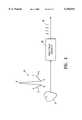
- FIG. 1is a schematic illustration of a system for revascularizing heart tissue which embodies features of the invention.
- FIG. 2is a transverse cross-section of the RF energy transmitting member of the system shown in FIG. 1 taken along the lines 2--2.
- FIG. 3is a schematic illustration of the one shot shown in FIG. 1.
- FIG. 4is a schematic illustration of a system for generating trigger signals based upon the patient's heart beat.
- FIG. 5is an elevational view of a delivery system for the RF energy emitter for positioning the operative distal end thereof adjacent to the endocardium of a patient's heart wall.
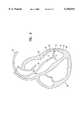
- FIG. 6is a schematic elevational view, partially in cross-section, of a human heart showing revascularization of the myocardium according to the invention.
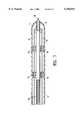
- FIG. 7is a schematic longitudinal cross-sectional view of the distal portion of a deflectable elongated RF system which embodies features of the invention.
- FIGS. 8 and 9are schematic longitudinal cross-sectional views of RF systems useful in the practice of this invention.
- FIG. 10is a schematic longitudinal cross-sectional view of a thermal energy ablation means useful in the practice of the invention.
- FIGS. 1 and 2depict an RF system 10 embodying features of the invention which includes an RF energy transmitting member 11 having a proximal end configured for electrical connection to a source 12 of RF energy and an uninsulated exposed distal end 13 which is configured to emit pulsed RF energy received from the source and transmitted through the RF energy transmitting member.
- the RF energy transmitting member 11includes an electrical conductor 14 which may be hollow or solid, a single or multiple strand and an insulating jacket 15 formed of suitable insulating polymeric material.
- a suitable source of RF energyis the Excaliber RF Generator from Aspen Laboratories (ConMed, Englewood, Colo., USA).
- the output from the RF energy source 12is pulsed by pulse-trigger system 16 which includes a one-shot 17, such as CD4047 sold by National Semiconductor, configured to receive trigger signals 18 through electrical conductor 19 and generate in response a pulsed output signal 20 connected to a NPN transistor 21.
- the pulsed output signal 20 from the one-shot 17actuates the transistor 21 for the duration of the output signal.
- the output of the transistor 21is connected to reed relay 22 which is configured to close upon receiving the output from the transistor 21.
- the output of the reed relay 22is connected in series to the foot switch 23. When the foot switch 23 is closed and reed relay 22 is closed, the RF energy source is actuated to emit RF energy for the duration of the output of the reed relay 22.
- FIG. 3illustrates in more detail the one-shot shown in FIG. 1 which has 14 pins, identified as pins a-n in FIG. 3.
- the one-shot shown in FIG. 3has the pins designated with letters a-n to avoid confusion with other reference numbers used herein.
- the one-shot model number CD4047has these pins numbered 1-14.
- the trigger signal 18 from an ECG unitis received by pin h and upon receipt of the trigger signal an on signal is emitted from pin j.
- the duration of the on signal from pin jis controlled by the resistance R and capacitance C from the RC circuit connected to pins a-c as shown.
- the resistance Rcan typically range from about 0.1 to about 1 meg ohm and the capacitance can typically range from about 0.08 to about 0.12 microfarads to control the duration of the pulses of output signal 20 from about 50 to about 300 msec.
- FIG. 4schematically illustrates a system of generating trigger signals 18 based upon the patient's heart cycle 30.
- the signals from the patient's heart 31are detected with a conventional ECG unit and the detected signals are transmitted to a trigger generating system 32 which may also be contained in the ECG unit.
- the trigger signal generating system 32is preprogrammed to emit one or more trigger signals 18 at a predetermined time between the R and the T wave of the heart cycle 30.
- FIG. 5illustrates a system for the percutaneous delivery of an RF system which has an outer catheter 40, a shaped distal end 41, a port 42 in the distal end of the outer catheter and an inner lumen extending within the outer catheter to the port in the distal end.
- This systemalso includes an inner catheter 44 which is slidably and rotatably disposed within the inner lumen of the outer catheter 40 and which has a shaped distal section 45, a distal end 46, a port 47 in the distal end of the inner catheter and an inner lumen 48 extending therein to the port in the distal end.
- An RF energy emitter 50is slidably disposed within the inner lumen of inner catheter 44.
- the distal section 45 of the inner catheter 44is at an angle with respect to the main shaft section 51 of the inner catheter to orient the RF energy emitter 50 extending out the distal end of the inner catheter.
- the disposition of the distal end 52 of the RF energy emitter 50can be controlled by raising and lowering and rotation of the RF energy emitter within the inner lumen of the inner catheter 44 and the inner catheter within the inner lumen of the outer catheter 40.
- the distal end 52 of the RF energy emitter 50is thus pointed in a desired direction to the endocardium defining the left ventricle 53. Longitudinal and rotational movement of the inner catheter 44 provides access to a large region of the endocardium.
- the present inventionalso comprises a method for revascularizing the myocardium 54 of a human heart 56.
- An RF system 10including an elongated shaft 60 with an RF energy emitter 50 disposed at the distal end is inserted into the vasculature of a patient, generally through one of the major vessels by the conventional Seldinger technique.
- the RF energy emitter 50is advanced into the left ventricle 53 and positioned against a desired portion of the heart muscle 62 in need of increased blood circulation due to cardiovascular disease.
- the RF energy emitter 50is activated and urged against the muscle 62 to effect removal of tissue, forming the revascularization channel 64.
- the tissue region disturbed or ablatedshould extend a desired distance through the endocardium 66 and into the myocardium 54 without perforating the epicardium 68.
- the RF energy emitter 50is deactivated, withdrawn from channel 64 and repositioned against another portion of muscle 62.
- an RF system 10 having an RF energy emitter 50 on the distal endis introduced through a small opening in the patient's chest wall.
- RF system 10is advanced until the RF energy emitter 50 is positioned against the ischemic portion of the heart muscle 62.
- the RF energy emitter 50is activated and urged towards the muscle 62.
- Tissueis removed sequentially from the epicardium 68, the myocardium 54 and the endocardium 66 to form the revascularization channel 64 into the left ventricle 53.
- the RF energy emitter 50is then deactivated, withdrawn from the muscle 62 and repositioned.
- the operatorrepeats the process until a sufficient number of channels 64 or similar revascularization sites are formed in muscle 62 to treat the ischemic condition.
- the RF energy emitter 50may be maintained in position on the heart muscle 62 by a controlled advance and gentle pressure, to insure that the RF energy emitter 50 is not dislodged during formation of the channel.
- the RF energy emitter 50can be maintained in place by applying a vacuum at the distal tip thereof.
- the operationmay be synchronized with the patient's heart cycle to avoid channel formation during the vulnerable period of the heart cycle.
- the RF energy emitter 50is subject to automatic control means which prevents operation during the T-wave portion of the ECG, as known in the art.
- the RF energy emitter 50may operate at two or more energy levels.
- the initial tissue removal to penetrate the endocardium 66is performed at a relatively high energy level.
- the rapid channel formation at this energy levelhelps anchor the RF energy emitter 50 within the channel 64.
- the remainder of the tissue removalmay be performed at a lower energy level to provide slower channel formation and greater control.
- control lines 70are connected at their distal ends to the distal end 72 of shaft 60 such as by adhesive bonding.
- Adhesive bondingmay utilize any of a variety of adhesives, including cyanoacrylate.
- At least two, and preferably four, control lines 70are thus axially, and preferably symmetrically, disposed about shaft 60. Axial movement of control lines 70 will thus change the angle of deflection of distal end 72 of shaft 60 with respect to its proximal end.
- a mechanismsuch as a ring or knob may be attached to the proximal ends of control lines 70 to allow manipulation of control lines 70.
- Control lines 70are preferably approximately 3-mil stainless steel wire, but may be similar filaments, such as nylon, or other suitable materials having appropriate tensile strength.
- an outer tubular member 74preferably encloses control lines 70 and shaft 60, forming a protective covering. Outer tubular member 74 is secured at its distal end to distal end 72 of shaft 60, rearward of RF energy emitter 50.
- control lines 70are routed through spaced apart channels 76 that are attached to the outer surface of shaft 60. Channels 76 are preferably constructed of 30 gauge polyamide tubing. Control lines 70 are thus guided to remain both separated and within well controlled areas on the exterior of shaft 60, thus allowing for the accurate guidance of the RF system 10 through the remote manipulation of control lines 70.
- Another means for guiding shaft 60 and RF energy emitter 50 into a proper position within the heartis to place the shaft 60 within a deflectable guiding catheter having dual axis steerability, for an added degree of steerability and control.
- Co-pending application, Ser. No. 08/438,743 filed May 10, 1995, entitled DELIVERY SYSTEM AND METHOD FOR MYOCARDIAL REVASCULARIZATIONdiscloses such a system and is hereby incorporated in its entirety by reference thereto. In practice, the positioning of the device may be viewed by esophageal ultrasound imaging, trans-thoracic ultrasound imaging and trans-thoracic fluoroscopic imaging.
- radiopaque marker bandsmay be added to the distal end 72 of shaft 60, for fluoroscopic imaging.
- RF energy emitter 50may thereby be aimed and controlled for forming channels 64 in the myocardium 54 of the ischemic heart muscle 62.
- FIG. 8illustrates the distal portion of an RF system 100 which has a thermal ablator 78.
- the thermal ablator 78has an electrode 80 wrapped around thermally-conductive probe 82 and extending the length of the system 100.
- the diameter of probe 82should be from about 1.0 to 5.0 mm.
- the proximal ends of the electrode 80are connected to a radiofrequency generating means (not shown). Applying radiofrequency energy at suitable frequency and power through electrode 80 produces resistive heating transmitted through probe 82.
- energy from about 30 MHz to about 10 GHzis suitable to generate sufficient heat at probe 82 to ablate heart tissue.
- Radiofrequency energymay also provide inductive heating as shown in FIG. 9.
- the distal portion of an RF system 10ahas a ferrite probe 84 on the end.
- a radiofrequency generating means(not shown) irradiates the patient's body with energy at a frequency to which body tissue is relatively transparent but the ferrite probe readily absorbs, generating ablating heat.
- Eighteen channelswere made in the heart of a live, anesthetized medium size dog by means of pulsed RF energy.
- the wattage and the size and type of distal tip of the RF delivery systemwere varied to determine the nature of the channels formed which result from such variations. The results are set forth in the table below.
- FIG. 10illustrates an embodiment with a means to form a revascularization channel comprising a thermal ablation means 90 that is a channel forming surface.
- the shaft 91generally includes two electrodes 92 that run the length of the shaft 91 and connect at the distal end of the device to a resistive themal probe 93.
- the proximal ends of the electrodes 92are connected to a variable power supply (not shown) configured to supply sufficient current through the resistive thermal probe 93 to generate heat capable of ablating the heart tissue.
- the probe 93should generally be about 0.1 to 5.0 mm in diameter.
- the thermal probe 93should heat to between about 60 degrees centigrade to about 600 degrees centigrade.
- the devicemay also comprise a sensing electrode 94 to monitor the temperature of the thermal probe 93.
- Such a devicecan be used in a method of forming a revascularization channel in a desired region of a wall of a patient's heart, the wall having an inner endocardium layer, an outer epicardium layer and an intermediate myocardium layer between the endocardium and the epicardium layers.
- the devicehaving proximal and distal ends and a means to form a revascularization channel comprising radiofrequency ablation means located on the distal end is introduced into the body of a patient.
- the distal end of the deviceis directed to the desired region of the wall wherein the revascularization channel is to be formed, and radiofrequency energy is supplied to the radiofrequency ablation means to form a revascularization channel in the myocardium layer.
- the radiofrequency ablation meanscan be a probe connected to a first and second electrode which extend the length of the device. Radiofrequency energy can can then be supplied across the electrodes to form a revascularization channel.
Landscapes
- Health & Medical Sciences (AREA)
- Life Sciences & Earth Sciences (AREA)
- Surgery (AREA)
- Engineering & Computer Science (AREA)
- Plasma & Fusion (AREA)
- Medical Informatics (AREA)
- Otolaryngology (AREA)
- Physics & Mathematics (AREA)
- Cardiology (AREA)
- Biomedical Technology (AREA)
- Heart & Thoracic Surgery (AREA)
- Nuclear Medicine, Radiotherapy & Molecular Imaging (AREA)
- Molecular Biology (AREA)
- Animal Behavior & Ethology (AREA)
- General Health & Medical Sciences (AREA)
- Public Health (AREA)
- Veterinary Medicine (AREA)
- Surgical Instruments (AREA)
Abstract
Description
__________________________________________________________________________WATTAGE DISTAL TIP TYPE UNINSULATED LENGTH PULSE DURATION # OF PULSES __________________________________________________________________________200 watts Hollow 0.05inch 100 msec 6 200 watts Hollow 0.05inch 100 msec 5 200 watts Hollow 0.05inch 100 msec 5 200 watts Hollow 0.05inch 100 msec 6 200 watts Hollow 0.05inch 100 msec 5 200 watts Hollow 0.05inch 100 msec 5 300 watts Hollow 0.05inch 100 msec 3 300 watts Hollow 0.05inch 100 msec 4 300 watts Hollow 0.05inch 100 msec 4 300 watts Hollow 0.05inch 100 msec 5 300 watts Hollow 0.05inch 100 msec 4 300 watts Hollow 0.05inch 100 msec 5 300 watts Solid 0.15inch 100 msec 4 300 watts Solid 0.15inch 100 msec 5 300 watts Solid 0.15inch 100 msec 6 300 watts Solid 0.15inch 100 msec 7 300 watts Solid 0.15inch 100 msec 5 300 watts Solid 0.15inch 100 msec 5 __________________________________________________________________________
Claims (8)
Priority Applications (6)
| Application Number | Priority Date | Filing Date | Title |
|---|---|---|---|
| US09/107,077US6156031A (en) | 1995-08-09 | 1998-06-29 | Transmyocardial revascularization using radiofrequency energy |
| PCT/US1998/020799WO1999017671A1 (en) | 1997-10-02 | 1998-10-02 | Transmyocardial revascularization using radiofrequency energy |
| EP98950873AEP1018961A1 (en) | 1997-10-02 | 1998-10-02 | Transmyocardial revascularization using radiofrequency energy |
| JP2000514573AJP2001518345A (en) | 1997-10-02 | 1998-10-02 | Myocardial revascularization using high frequency energy |
| CA002305333ACA2305333A1 (en) | 1997-10-02 | 1998-10-02 | Transmyocardial revascularization using radiofrequency energy |
| AU96803/98AAU9680398A (en) | 1997-10-02 | 1998-10-02 | Transmyocardial revascularization using radiofrequency energy |
Applications Claiming Priority (4)
| Application Number | Priority Date | Filing Date | Title |
|---|---|---|---|
| US51749995A | 1995-08-09 | 1995-08-09 | |
| US08/942,874US6267757B1 (en) | 1995-08-09 | 1997-10-02 | Revascularization with RF ablation |
| US96818497A | 1997-11-12 | 1997-11-12 | |
| US09/107,077US6156031A (en) | 1995-08-09 | 1998-06-29 | Transmyocardial revascularization using radiofrequency energy |
Related Parent Applications (2)
| Application Number | Title | Priority Date | Filing Date |
|---|---|---|---|
| US08/942,874Continuation-In-PartUS6267757B1 (en) | 1995-08-09 | 1997-10-02 | Revascularization with RF ablation |
| US96818497AContinuation-In-Part | 1995-08-09 | 1997-11-12 |
Publications (1)
| Publication Number | Publication Date |
|---|---|
| US6156031Atrue US6156031A (en) | 2000-12-05 |
Family
ID=27414666
Family Applications (1)
| Application Number | Title | Priority Date | Filing Date |
|---|---|---|---|
| US09/107,077Expired - LifetimeUS6156031A (en) | 1995-08-09 | 1998-06-29 | Transmyocardial revascularization using radiofrequency energy |
Country Status (1)
| Country | Link |
|---|---|
| US (1) | US6156031A (en) |
Cited By (101)
| Publication number | Priority date | Publication date | Assignee | Title |
|---|---|---|---|---|
| US6332881B1 (en)* | 1999-09-01 | 2001-12-25 | Cardima, Inc. | Surgical ablation tool |
| US20020007138A1 (en)* | 1998-09-10 | 2002-01-17 | Percardia, Inc. | Left ventricular conduit with blood vessel graft |
| US6387119B2 (en) | 1998-09-10 | 2002-05-14 | Percardia, Inc. | Delivery methods for left ventricular conduit |
| US20020068930A1 (en)* | 1995-11-22 | 2002-06-06 | Arthrocare Corporation | Systems and methods for electrosurgical tendon vascularization |
| US6409751B1 (en) | 1998-09-10 | 2002-06-25 | Percardia, Inc. | Stent delivery system and method of use |
| US20020100485A1 (en)* | 1993-02-22 | 2002-08-01 | Stevens John H. | Method and apparatus for thoracoscopic intracardiac procedures |
| US20030004302A1 (en)* | 2001-05-15 | 2003-01-02 | Satoshi Okamoto | Process for producing purified polyether sulfones |
| US20030097162A1 (en)* | 2001-11-20 | 2003-05-22 | Syeneron Medical Ltd. | System and method for skin treatment using electrical current |
| US6695836B1 (en)* | 2000-07-03 | 2004-02-24 | Radius Medical Technologies, Inc. | Device and method for myocardial revascularization |
| US6733516B2 (en) | 2001-01-17 | 2004-05-11 | Scimed Life Systems, Inc. | Method and apparatus for limiting revascularization to viable tissue |
| US6746447B2 (en) | 1993-05-10 | 2004-06-08 | Arthrocare Corporation | Methods for ablating tissue |
| US6749604B1 (en) | 1993-05-10 | 2004-06-15 | Arthrocare Corporation | Electrosurgical instrument with axially-spaced electrodes |
| US6763836B2 (en) | 1998-06-02 | 2004-07-20 | Arthrocare Corporation | Methods for electrosurgical tendon vascularization |
| US20040267257A1 (en)* | 2003-06-30 | 2004-12-30 | George Bourne | Apparatus and methods for delivering energy to a target site within bone |
| US6854467B2 (en) | 2000-05-04 | 2005-02-15 | Percardia, Inc. | Methods and devices for delivering a ventricular stent |
| US6896674B1 (en) | 1993-05-10 | 2005-05-24 | Arthrocare Corporation | Electrosurgical apparatus having digestion electrode and methods related thereto |
| US6913021B2 (en) | 1996-08-13 | 2005-07-05 | Percardia, Inc. | Method for revascularizing a coronary vessel |
| US6916304B2 (en) | 1999-05-04 | 2005-07-12 | Percardia, Inc. | Transmyocardial implant with flow reduction |
| US6926690B2 (en) | 1998-09-10 | 2005-08-09 | Percardia, Inc. | Transmyocardial shunt and its attachment mechanism, for left ventricular revascularization |
| US6949096B2 (en) | 1998-01-21 | 2005-09-27 | Arthrocare Corporation | Electrosurgical ablation and aspiration apparatus having flow directing feature and methods related thereto |
| US6949118B2 (en) | 2002-01-16 | 2005-09-27 | Percardia, Inc. | Encased implant and methods |
| US6949080B2 (en) | 1998-01-30 | 2005-09-27 | Percardia, Inc. | Left ventricular conduits to coronary arteries and methods for coronary bypass |
| US6953481B2 (en) | 1998-09-10 | 2005-10-11 | Percardia, Inc. | Designs for left ventricular conduit |
| US6964652B2 (en) | 1999-08-04 | 2005-11-15 | Percardia, Inc. | Left ventricular conduits and methods for delivery |
| US20050267459A1 (en)* | 2004-05-27 | 2005-12-01 | Belhe Kedar R | Curved ablation catheter |
| US20050277918A1 (en)* | 2003-03-07 | 2005-12-15 | Baylis Medical Company Inc. | Electrosurgical cannula |
| US6976990B2 (en) | 2001-01-25 | 2005-12-20 | Percardia, Inc. | Intravascular ventriculocoronary bypass via a septal passageway |
| US6991631B2 (en) | 2000-06-09 | 2006-01-31 | Arthrocare Corporation | Electrosurgical probe having circular electrode array for ablating joint tissue and systems related thereto |
| US7008397B2 (en) | 2002-02-13 | 2006-03-07 | Percardia, Inc. | Cardiac implant and methods |
| US7011095B2 (en) | 1998-09-10 | 2006-03-14 | Percardia, Inc. | Valve designs for left ventricular conduits |
| US7033372B1 (en) | 1999-08-04 | 2006-04-25 | Percardia, Inc. | Corkscrew reinforced left ventricle to coronary artery channel |
| US20060142756A1 (en)* | 2003-01-21 | 2006-06-29 | Baylis Medical Company Inc. | Method of surgical perforation via the delivery of energy |
| US7094215B2 (en) | 1997-10-02 | 2006-08-22 | Arthrocare Corporation | Systems and methods for electrosurgical tissue contraction |
| US7201750B1 (en) | 1992-01-07 | 2007-04-10 | Arthrocare Corporation | System for treating articular cartilage defects |
| US7276063B2 (en) | 1998-08-11 | 2007-10-02 | Arthrocare Corporation | Instrument for electrosurgical tissue treatment |
| US7326219B2 (en) | 2002-09-09 | 2008-02-05 | Wilk Patent Development | Device for placing transmyocardial implant |
| US7422585B1 (en)* | 1992-01-07 | 2008-09-09 | Arthrocare Corporation | System for electrosurgical myocardial revascularization |
| US7429260B2 (en) | 1996-07-16 | 2008-09-30 | Arthrocare Corporation | Systems and methods for electrosurgical tissue contraction within the spine |
| US7435247B2 (en) | 1998-08-11 | 2008-10-14 | Arthrocare Corporation | Systems and methods for electrosurgical tissue treatment |
| US7505812B1 (en) | 1993-05-10 | 2009-03-17 | Arthrocare Corporation | Electrosurgical system for treating restenosis of body lumens |
| US20090264987A1 (en)* | 2008-04-18 | 2009-10-22 | Medtronic Vascular, Inc. | Stent Graft Delivery System and Method of Use |
| US20100094277A1 (en)* | 2008-10-09 | 2010-04-15 | Olympus Medical Systems Corp. | High-frequency surgical device and method |
| US8012153B2 (en) | 2003-07-16 | 2011-09-06 | Arthrocare Corporation | Rotary electrosurgical apparatus and methods thereof |
| US8317786B2 (en) | 2009-09-25 | 2012-11-27 | AthroCare Corporation | System, method and apparatus for electrosurgical instrument with movable suction sheath |
| US8323279B2 (en) | 2009-09-25 | 2012-12-04 | Arthocare Corporation | System, method and apparatus for electrosurgical instrument with movable fluid delivery sheath |
| US8355799B2 (en) | 2008-12-12 | 2013-01-15 | Arthrocare Corporation | Systems and methods for limiting joint temperature |
| US8696659B2 (en) | 2010-04-30 | 2014-04-15 | Arthrocare Corporation | Electrosurgical system and method having enhanced temperature measurement |
| US8747400B2 (en) | 2008-08-13 | 2014-06-10 | Arthrocare Corporation | Systems and methods for screen electrode securement |
| US9265563B2 (en) | 2006-02-22 | 2016-02-23 | Custom Medical Applications, Inc. | Ablation instruments and related methods |
| US9526556B2 (en) | 2014-02-28 | 2016-12-27 | Arthrocare Corporation | Systems and methods systems related to electrosurgical wands with screen electrodes |
| US9597142B2 (en) | 2014-07-24 | 2017-03-21 | Arthrocare Corporation | Method and system related to electrosurgical procedures |
| US9649148B2 (en) | 2014-07-24 | 2017-05-16 | Arthrocare Corporation | Electrosurgical system and method having enhanced arc prevention |
| US20210113259A1 (en)* | 2019-10-21 | 2021-04-22 | Biosense Webster (Israel) Ltd. | Ablation of lesions of low-medium depths using ultrahigh radiofrequency (rf) power for ultrashort durations |
| US10993805B2 (en) | 2008-02-26 | 2021-05-04 | Jenavalve Technology, Inc. | Stent for the positioning and anchoring of a valvular prosthesis in an implantation site in the heart of a patient |
| US11065138B2 (en) | 2016-05-13 | 2021-07-20 | Jenavalve Technology, Inc. | Heart valve prosthesis delivery system and method for delivery of heart valve prosthesis with introducer sheath and loading system |
| US11185405B2 (en) | 2013-08-30 | 2021-11-30 | Jenavalve Technology, Inc. | Radially collapsible frame for a prosthetic valve and method for manufacturing such a frame |
| US11197754B2 (en) | 2017-01-27 | 2021-12-14 | Jenavalve Technology, Inc. | Heart valve mimicry |
| US11337800B2 (en) | 2015-05-01 | 2022-05-24 | Jenavalve Technology, Inc. | Device and method with reduced pacemaker rate in heart valve replacement |
| US11357624B2 (en) | 2007-04-13 | 2022-06-14 | Jenavalve Technology, Inc. | Medical device for treating a heart valve insufficiency |
| US20220226043A1 (en)* | 2015-08-21 | 2022-07-21 | Baylis Medical Company Inc. | Transvascular Electrosurgical Devices and Systems and Methods of using the same |
| US11517431B2 (en) | 2005-01-20 | 2022-12-06 | Jenavalve Technology, Inc. | Catheter system for implantation of prosthetic heart valves |
| US11564794B2 (en) | 2008-02-26 | 2023-01-31 | Jenavalve Technology, Inc. | Stent for the positioning and anchoring of a valvular prosthesis in an implantation site in the heart of a patient |
| US11589981B2 (en) | 2010-05-25 | 2023-02-28 | Jenavalve Technology, Inc. | Prosthetic heart valve and transcatheter delivered endoprosthesis comprising a prosthetic heart valve and a stent |
| US11660137B2 (en) | 2006-09-29 | 2023-05-30 | Boston Scientific Medical Device Limited | Connector system for electrosurgical device |
| US11684447B2 (en) | 2012-05-31 | 2023-06-27 | Boston Scientific Medical Device Limited | Radiofrequency perforation apparatus |
| US11724070B2 (en) | 2019-12-19 | 2023-08-15 | Boston Scientific Medical Device Limited | Methods for determining a position of a first medical device with respect to a second medical device, and related systems and medical devices |
| US11744638B2 (en) | 2006-09-29 | 2023-09-05 | Boston Scientific Medical Device Limited | Electrosurgical device |
| US11759190B2 (en) | 2019-10-18 | 2023-09-19 | Boston Scientific Medical Device Limited | Lock for medical devices, and related systems and methods |
| US11766290B2 (en) | 2015-09-09 | 2023-09-26 | Boston Scientific Medical Device Limited | Epicardial access system and methods |
| US11793446B2 (en) | 2020-06-17 | 2023-10-24 | Boston Scientific Medical Device Limited | Electroanatomical mapping system with visualization of energy-delivery and elongated needle assemblies |
| US11801087B2 (en) | 2019-11-13 | 2023-10-31 | Boston Scientific Medical Device Limited | Apparatus and methods for puncturing tissue |
| US11819243B2 (en) | 2020-03-19 | 2023-11-21 | Boston Scientific Medical Device Limited | Medical sheath and related systems and methods |
| US11826075B2 (en) | 2020-04-07 | 2023-11-28 | Boston Scientific Medical Device Limited | Elongated medical assembly |
| US11878131B2 (en) | 2017-12-05 | 2024-01-23 | Boston Scientific Medical Device Limited | Transseptal guide wire puncture system |
| US11931098B2 (en) | 2020-02-19 | 2024-03-19 | Boston Scientific Medical Device Limited | System and method for carrying out a medical procedure |
| US11937873B2 (en) | 2013-03-12 | 2024-03-26 | Boston Scientific Medical Device Limited | Electrosurgical device having a lumen |
| US11938285B2 (en) | 2020-06-17 | 2024-03-26 | Boston Scientific Medical Device Limited | Stop-movement device for elongated medical assembly |
| US11937796B2 (en) | 2020-06-18 | 2024-03-26 | Boston Scientific Medical Device Limited | Tissue-spreader assembly |
| US11980412B2 (en) | 2020-09-15 | 2024-05-14 | Boston Scientific Medical Device Limited | Elongated medical sheath |
| US11986209B2 (en) | 2020-02-25 | 2024-05-21 | Boston Scientific Medical Device Limited | Methods and devices for creation of communication between aorta and left atrium |
| US11998238B2 (en) | 2013-08-07 | 2024-06-04 | Boston Scientific Medical Device Limited | Methods and devices for puncturing tissue |
| US12005202B2 (en) | 2020-08-07 | 2024-06-11 | Boston Scientific Medical Device Limited | Catheter having tissue-engaging device |
| US12011279B2 (en) | 2020-04-07 | 2024-06-18 | Boston Scientific Medical Device Limited | Electro-anatomic mapping system |
| US12011210B2 (en) | 2013-03-15 | 2024-06-18 | Boston Scientific Medical Device Limited | Electrosurgical device having a distal aperture |
| US12042178B2 (en) | 2020-07-21 | 2024-07-23 | Boston Scientific Medical Device Limited | System of medical devices and method for pericardial puncture |
| US12082792B2 (en) | 2020-02-25 | 2024-09-10 | Boston Scientific Medical Device Limited | Systems and methods for creating a puncture between aorta and the left atrium |
| US12121461B2 (en) | 2015-03-20 | 2024-10-22 | Jenavalve Technology, Inc. | Heart valve prosthesis delivery system and method for delivery of heart valve prosthesis with introducer sheath |
| US12128199B2 (en) | 2016-01-07 | 2024-10-29 | Boston Scientific Medical Device Limited | Hybrid transseptal dilator and methods of using the same |
| US12156642B2 (en) | 2019-04-29 | 2024-12-03 | Boston Scientific Medical Device Limited | Transseptal systems, devices and methods |
| US12171658B2 (en) | 2022-11-09 | 2024-12-24 | Jenavalve Technology, Inc. | Catheter system for sequential deployment of an expandable implant |
| US12171622B2 (en) | 2017-08-10 | 2024-12-24 | Boston Scientific Medical Device Limited | Heat exchange and temperature sensing device and method of use |
| US12207836B2 (en) | 2016-11-01 | 2025-01-28 | Boston Scientific Medical Device Limited | Methods and devices for puncturing tissue |
| US12220543B2 (en) | 2020-09-10 | 2025-02-11 | Boston Scientific Medical Device Limited | Elongated medical catheter including marker band |
| US12251159B2 (en) | 2013-03-12 | 2025-03-18 | Boston Scientific Medical Device Limited | Medical device having a support structure |
| US12257401B2 (en) | 2013-12-20 | 2025-03-25 | Boston Scientific Medical Device Limited | Steerable medical device handle |
| US12343042B2 (en) | 2020-07-16 | 2025-07-01 | Boston Scientific Medical Device Limited | Pericardial puncture device and method |
| US12370354B2 (en) | 2018-05-08 | 2025-07-29 | Boston Scientific Medical Device Limited | Coupling mechanisms for medical devices |
| US12396785B2 (en) | 2020-08-12 | 2025-08-26 | Boston Scientific Medical Device Limited | System of medical devices and method for pericardial puncture |
| US12414854B2 (en) | 2010-05-20 | 2025-09-16 | Jenavalve Technology, Inc. | Catheter system for introducing an expandable stent into the body of a patient |
| US12420067B2 (en) | 2020-05-12 | 2025-09-23 | Boston Scientific Medical Device Limited | Guidewire assembly |
| US12440266B2 (en)* | 2022-04-08 | 2025-10-14 | Boston Scientific Medical Device Limited | Transvascular electrosurgical devices and systems and methods of using the same |
Citations (71)
| Publication number | Priority date | Publication date | Assignee | Title |
|---|---|---|---|---|
| US4211230A (en)* | 1978-07-31 | 1980-07-08 | Sybron Corporation | Electrosurgical coagulation |
| US4682596A (en)* | 1984-05-22 | 1987-07-28 | Cordis Corporation | Electrosurgical catheter and method for vascular applications |
| US4896671A (en)* | 1988-08-01 | 1990-01-30 | C. R. Bard, Inc. | Catheter with contoured ablation electrode |
| EP0428812A1 (en)* | 1989-07-24 | 1991-05-29 | Consiglio Nazionale Delle Ricerche | Intracardiac catheter, magneto-cardiographically localizable, for mapping and pacing provided with means for ablation of arrythmogenic tissue |
| US5098431A (en)* | 1989-04-13 | 1992-03-24 | Everest Medical Corporation | RF ablation catheter |
| US5104393A (en)* | 1989-08-30 | 1992-04-14 | Angelase, Inc. | Catheter |
| US5122138A (en)* | 1990-11-28 | 1992-06-16 | Manwaring Kim H | Tissue vaporizing accessory and method for an endoscope |
| US5125926A (en)* | 1990-09-24 | 1992-06-30 | Laser Engineering, Inc. | Heart-synchronized pulsed laser system |
| US5172699A (en)* | 1990-10-19 | 1992-12-22 | Angelase, Inc. | Process of identification of a ventricular tachycardia (VT) active site and an ablation catheter system |
| US5188635A (en)* | 1988-02-08 | 1993-02-23 | Wolfgang Radtke | Catheter for percutaneous surgery of blood vessels and organs using radiant energy |
| US5197963A (en)* | 1991-12-02 | 1993-03-30 | Everest Medical Corporation | Electrosurgical instrument with extendable sheath for irrigation and aspiration |
| US5215103A (en)* | 1986-11-14 | 1993-06-01 | Desai Jawahar M | Catheter for mapping and ablation and method therefor |
| US5222501A (en)* | 1992-01-31 | 1993-06-29 | Duke University | Methods for the diagnosis and ablation treatment of ventricular tachycardia |
| US5230349A (en)* | 1988-11-25 | 1993-07-27 | Sensor Electronics, Inc. | Electrical heating catheter |
| US5231995A (en)* | 1986-11-14 | 1993-08-03 | Desai Jawahar M | Method for catheter mapping and ablation |
| US5257635A (en)* | 1988-11-25 | 1993-11-02 | Sensor Electronics, Inc. | Electrical heating catheter |
| US5281213A (en)* | 1992-04-16 | 1994-01-25 | Implemed, Inc. | Catheter for ice mapping and ablation |
| US5281218A (en)* | 1992-06-05 | 1994-01-25 | Cardiac Pathways Corporation | Catheter having needle electrode for radiofrequency ablation |
| US5287861A (en)* | 1992-10-30 | 1994-02-22 | Wilk Peter J | Coronary artery by-pass method and associated catheter |
| US5295484A (en)* | 1992-05-19 | 1994-03-22 | Arizona Board Of Regents For And On Behalf Of The University Of Arizona | Apparatus and method for intra-cardiac ablation of arrhythmias |
| WO1994010904A1 (en)* | 1992-11-13 | 1994-05-26 | American Cardiac Ablation Co., Inc. | Apparatus and method for monitoring endocardial signal during ablation |
| US5334193A (en)* | 1992-11-13 | 1994-08-02 | American Cardiac Ablation Co., Inc. | Fluid cooled ablation catheter |
| WO1994021168A1 (en)* | 1993-03-16 | 1994-09-29 | Ep Technologies, Inc. | Cardiac mapping and ablation systems |
| WO1994021167A1 (en)* | 1993-03-16 | 1994-09-29 | Ep Technologies, Inc. | Multiple layer guide body for cardiac mapping and ablation catheters |
| WO1994021165A1 (en)* | 1993-03-16 | 1994-09-29 | Ep Technologies, Inc. | Guide sheaths for cardiac mapping and ablation |
| US5370644A (en)* | 1988-11-25 | 1994-12-06 | Sensor Electronics, Inc. | Radiofrequency ablation catheter |
| US5385148A (en)* | 1993-07-30 | 1995-01-31 | The Regents Of The University Of California | Cardiac imaging and ablation catheter |
| US5389096A (en)* | 1990-12-18 | 1995-02-14 | Advanced Cardiovascular Systems | System and method for percutaneous myocardial revascularization |
| US5391199A (en)* | 1993-07-20 | 1995-02-21 | Biosense, Inc. | Apparatus and method for treating cardiac arrhythmias |
| US5398683A (en)* | 1991-05-24 | 1995-03-21 | Ep Technologies, Inc. | Combination monophasic action potential/ablation catheter and high-performance filter system |
| US5423882A (en)* | 1991-12-26 | 1995-06-13 | Cordis-Webster, Inc. | Catheter having electrode with annular recess and method of using same |
| US5431649A (en)* | 1993-08-27 | 1995-07-11 | Medtronic, Inc. | Method and apparatus for R-F ablation |
| US5433198A (en)* | 1993-03-11 | 1995-07-18 | Desai; Jawahar M. | Apparatus and method for cardiac ablation |
| US5441499A (en)* | 1993-07-14 | 1995-08-15 | Dekna Elektro-U. Medizinische Apparatebau Gesellschaft Mbh | Bipolar radio-frequency surgical instrument |
| US5487757A (en)* | 1993-07-20 | 1996-01-30 | Medtronic Cardiorhythm | Multicurve deflectable catheter |
| US5492119A (en)* | 1993-12-22 | 1996-02-20 | Heart Rhythm Technologies, Inc. | Catheter tip stabilizing apparatus |
| US5500012A (en)* | 1992-07-15 | 1996-03-19 | Angeion Corporation | Ablation catheter system |
| US5507802A (en)* | 1993-06-02 | 1996-04-16 | Cardiac Pathways Corporation | Method of mapping and/or ablation using a catheter having a tip with fixation means |
| US5540681A (en)* | 1992-04-10 | 1996-07-30 | Medtronic Cardiorhythm | Method and system for radiofrequency ablation of tissue |
| US5545200A (en)* | 1993-07-20 | 1996-08-13 | Medtronic Cardiorhythm | Steerable electrophysiology catheter |
| WO1996026675A1 (en)* | 1995-02-28 | 1996-09-06 | Boston Scientific Corporation | Deflectable catheter for ablating cardiac tissue |
| US5562619A (en)* | 1993-08-19 | 1996-10-08 | Boston Scientific Corporation | Deflectable catheter |
| US5571088A (en)* | 1993-07-01 | 1996-11-05 | Boston Scientific Corporation | Ablation catheters |
| US5573533A (en)* | 1992-04-10 | 1996-11-12 | Medtronic Cardiorhythm | Method and system for radiofrequency ablation of cardiac tissue |
| US5578007A (en)* | 1992-06-05 | 1996-11-26 | Cardiac Pathways Corporation | Endocardial mapping and ablation system utilizing a separately controlled ablation catheter and method |
| US5579764A (en)* | 1993-01-08 | 1996-12-03 | Goldreyer; Bruce N. | Method and apparatus for spatially specific electrophysiological sensing in a catheter with an enlarged ablating electrode |
| US5591159A (en)* | 1994-11-09 | 1997-01-07 | Taheri; Syde A. | Transcavitary myocardial perfusion apparatus |
| US5599345A (en)* | 1993-11-08 | 1997-02-04 | Zomed International, Inc. | RF treatment apparatus |
| US5607462A (en)* | 1993-09-24 | 1997-03-04 | Cardiac Pathways Corporation | Catheter assembly, catheter and multi-catheter introducer for use therewith |
| US5607421A (en)* | 1991-05-01 | 1997-03-04 | The Trustees Of Columbia University In The City Of New York | Myocardial revascularization through the endocardial surface using a laser |
| US5609151A (en)* | 1994-09-08 | 1997-03-11 | Medtronic, Inc. | Method for R-F ablation |
| US5620439A (en)* | 1995-06-06 | 1997-04-15 | George S. Abela | Catheter and technique for endovascular myocardial revascularization |
| US5620481A (en)* | 1991-07-05 | 1997-04-15 | Desai; Jawahar M. | Device for multi-phase radio-frequency ablation |
| US5626575A (en)* | 1995-04-28 | 1997-05-06 | Conmed Corporation | Power level control apparatus for electrosurgical generators |
| US5637090A (en)* | 1993-10-15 | 1997-06-10 | Ep Technologies, Inc. | Multiple electrode element for mapping and ablating heart tissue |
| US5658278A (en)* | 1992-12-01 | 1997-08-19 | Cardiac Pathways, Inc. | Catheter for RF ablation with cooled electrode and method |
| US5657755A (en)* | 1993-03-11 | 1997-08-19 | Desai; Jawahar M. | Apparatus and method for cardiac ablation |
| US5662124A (en)* | 1996-06-19 | 1997-09-02 | Wilk Patent Development Corp. | Coronary artery by-pass method |
| US5672170A (en)* | 1996-06-20 | 1997-09-30 | Cynosure, Inc. | Laser transmyocardial revascularization arrangement |
| EP0797956A2 (en)* | 1996-03-29 | 1997-10-01 | Medtronic, Inc. | Slip resistant, field focusing ablation catheter electrode |
| US5683366A (en)* | 1992-01-07 | 1997-11-04 | Arthrocare Corporation | System and method for electrosurgical tissue canalization |
| US5697882A (en)* | 1992-01-07 | 1997-12-16 | Arthrocare Corporation | System and method for electrosurgical cutting and ablation |
| US5722975A (en)* | 1991-11-08 | 1998-03-03 | E.P. Technologies Inc. | Systems for radiofrequency ablation with phase sensitive power detection and control |
| US5725523A (en)* | 1996-03-29 | 1998-03-10 | Mueller; Richard L. | Lateral-and posterior-aspect method and apparatus for laser-assisted transmyocardial revascularization and other surgical applications |
| US5728144A (en)* | 1992-04-13 | 1998-03-17 | Ep Technologies, Inc. | Steerable coaxial cable systems for cardiac ablation |
| US5741249A (en)* | 1996-10-16 | 1998-04-21 | Fidus Medical Technology Corporation | Anchoring tip assembly for microwave ablation catheter |
| US5743903A (en)* | 1991-11-08 | 1998-04-28 | Ep Technologies, Inc. | Cardiac ablation systems and methods using tissue temperature monitoring and control |
| US5755714A (en)* | 1996-09-17 | 1998-05-26 | Eclipse Surgical Technologies, Inc. | Shaped catheter for transmyocardial revascularization |
| US5769843A (en)* | 1996-02-20 | 1998-06-23 | Cormedica | Percutaneous endomyocardial revascularization |
| US5785059A (en)* | 1997-04-03 | 1998-07-28 | Incontrol, Inc. | Method of releasing conductive elements from fibrotic tissue |
| US5843019A (en)* | 1992-01-07 | 1998-12-01 | Arthrocare Corporation | Shaped electrodes and methods for electrosurgical cutting and ablation |
- 1998
- 1998-06-29USUS09/107,077patent/US6156031A/ennot_activeExpired - Lifetime
Patent Citations (81)
| Publication number | Priority date | Publication date | Assignee | Title |
|---|---|---|---|---|
| US4211230A (en)* | 1978-07-31 | 1980-07-08 | Sybron Corporation | Electrosurgical coagulation |
| US4682596A (en)* | 1984-05-22 | 1987-07-28 | Cordis Corporation | Electrosurgical catheter and method for vascular applications |
| US5500011A (en)* | 1986-11-14 | 1996-03-19 | Desai; Jawahar M. | Catheter for mapping and ablation and method therefor |
| US5397339A (en)* | 1986-11-14 | 1995-03-14 | Desai; Jawahar M. | Catheter for mapping and ablation and method therefor |
| US5215103A (en)* | 1986-11-14 | 1993-06-01 | Desai Jawahar M | Catheter for mapping and ablation and method therefor |
| US5231995A (en)* | 1986-11-14 | 1993-08-03 | Desai Jawahar M | Method for catheter mapping and ablation |
| US5188635A (en)* | 1988-02-08 | 1993-02-23 | Wolfgang Radtke | Catheter for percutaneous surgery of blood vessels and organs using radiant energy |
| US4896671A (en)* | 1988-08-01 | 1990-01-30 | C. R. Bard, Inc. | Catheter with contoured ablation electrode |
| US5257635A (en)* | 1988-11-25 | 1993-11-02 | Sensor Electronics, Inc. | Electrical heating catheter |
| US5230349A (en)* | 1988-11-25 | 1993-07-27 | Sensor Electronics, Inc. | Electrical heating catheter |
| US5370644A (en)* | 1988-11-25 | 1994-12-06 | Sensor Electronics, Inc. | Radiofrequency ablation catheter |
| US5098431A (en)* | 1989-04-13 | 1992-03-24 | Everest Medical Corporation | RF ablation catheter |
| EP0428812A1 (en)* | 1989-07-24 | 1991-05-29 | Consiglio Nazionale Delle Ricerche | Intracardiac catheter, magneto-cardiographically localizable, for mapping and pacing provided with means for ablation of arrythmogenic tissue |
| US5056517A (en)* | 1989-07-24 | 1991-10-15 | Consiglio Nazionale Delle Ricerche | Biomagnetically localizable multipurpose catheter and method for magnetocardiographic guided intracardiac mapping, biopsy and ablation of cardiac arrhythmias |
| US5104393A (en)* | 1989-08-30 | 1992-04-14 | Angelase, Inc. | Catheter |
| US5125926A (en)* | 1990-09-24 | 1992-06-30 | Laser Engineering, Inc. | Heart-synchronized pulsed laser system |
| US5172699A (en)* | 1990-10-19 | 1992-12-22 | Angelase, Inc. | Process of identification of a ventricular tachycardia (VT) active site and an ablation catheter system |
| US5122138A (en)* | 1990-11-28 | 1992-06-16 | Manwaring Kim H | Tissue vaporizing accessory and method for an endoscope |
| US5389096A (en)* | 1990-12-18 | 1995-02-14 | Advanced Cardiovascular Systems | System and method for percutaneous myocardial revascularization |
| US5607421A (en)* | 1991-05-01 | 1997-03-04 | The Trustees Of Columbia University In The City Of New York | Myocardial revascularization through the endocardial surface using a laser |
| US5398683A (en)* | 1991-05-24 | 1995-03-21 | Ep Technologies, Inc. | Combination monophasic action potential/ablation catheter and high-performance filter system |
| US5620481A (en)* | 1991-07-05 | 1997-04-15 | Desai; Jawahar M. | Device for multi-phase radio-frequency ablation |
| US5722975A (en)* | 1991-11-08 | 1998-03-03 | E.P. Technologies Inc. | Systems for radiofrequency ablation with phase sensitive power detection and control |
| US5743903A (en)* | 1991-11-08 | 1998-04-28 | Ep Technologies, Inc. | Cardiac ablation systems and methods using tissue temperature monitoring and control |
| US5197963A (en)* | 1991-12-02 | 1993-03-30 | Everest Medical Corporation | Electrosurgical instrument with extendable sheath for irrigation and aspiration |
| US5522873A (en)* | 1991-12-26 | 1996-06-04 | Webster Laboratories, Inc. | Catheter having electrode with annular recess and method of using same |
| US5423882A (en)* | 1991-12-26 | 1995-06-13 | Cordis-Webster, Inc. | Catheter having electrode with annular recess and method of using same |
| US5843019A (en)* | 1992-01-07 | 1998-12-01 | Arthrocare Corporation | Shaped electrodes and methods for electrosurgical cutting and ablation |
| US5683366A (en)* | 1992-01-07 | 1997-11-04 | Arthrocare Corporation | System and method for electrosurgical tissue canalization |
| US5697882A (en)* | 1992-01-07 | 1997-12-16 | Arthrocare Corporation | System and method for electrosurgical cutting and ablation |
| US5222501A (en)* | 1992-01-31 | 1993-06-29 | Duke University | Methods for the diagnosis and ablation treatment of ventricular tachycardia |
| US5573533A (en)* | 1992-04-10 | 1996-11-12 | Medtronic Cardiorhythm | Method and system for radiofrequency ablation of cardiac tissue |
| US5540681A (en)* | 1992-04-10 | 1996-07-30 | Medtronic Cardiorhythm | Method and system for radiofrequency ablation of tissue |
| US5728144A (en)* | 1992-04-13 | 1998-03-17 | Ep Technologies, Inc. | Steerable coaxial cable systems for cardiac ablation |
| US5281213A (en)* | 1992-04-16 | 1994-01-25 | Implemed, Inc. | Catheter for ice mapping and ablation |
| US5295484A (en)* | 1992-05-19 | 1994-03-22 | Arizona Board Of Regents For And On Behalf Of The University Of Arizona | Apparatus and method for intra-cardiac ablation of arrhythmias |
| US5578007A (en)* | 1992-06-05 | 1996-11-26 | Cardiac Pathways Corporation | Endocardial mapping and ablation system utilizing a separately controlled ablation catheter and method |
| US5281218A (en)* | 1992-06-05 | 1994-01-25 | Cardiac Pathways Corporation | Catheter having needle electrode for radiofrequency ablation |
| US5500012A (en)* | 1992-07-15 | 1996-03-19 | Angeion Corporation | Ablation catheter system |
| US5287861A (en)* | 1992-10-30 | 1994-02-22 | Wilk Peter J | Coronary artery by-pass method and associated catheter |
| WO1994010904A1 (en)* | 1992-11-13 | 1994-05-26 | American Cardiac Ablation Co., Inc. | Apparatus and method for monitoring endocardial signal during ablation |
| US5334193A (en)* | 1992-11-13 | 1994-08-02 | American Cardiac Ablation Co., Inc. | Fluid cooled ablation catheter |
| US5658278A (en)* | 1992-12-01 | 1997-08-19 | Cardiac Pathways, Inc. | Catheter for RF ablation with cooled electrode and method |
| US5579764A (en)* | 1993-01-08 | 1996-12-03 | Goldreyer; Bruce N. | Method and apparatus for spatially specific electrophysiological sensing in a catheter with an enlarged ablating electrode |
| US5433198A (en)* | 1993-03-11 | 1995-07-18 | Desai; Jawahar M. | Apparatus and method for cardiac ablation |
| US5657755A (en)* | 1993-03-11 | 1997-08-19 | Desai; Jawahar M. | Apparatus and method for cardiac ablation |
| US5476495A (en)* | 1993-03-16 | 1995-12-19 | Ep Technologies, Inc. | Cardiac mapping and ablation systems |
| US5636634A (en)* | 1993-03-16 | 1997-06-10 | Ep Technologies, Inc. | Systems using guide sheaths for introducing, deploying, and stabilizing cardiac mapping and ablation probes |
| WO1994021165A1 (en)* | 1993-03-16 | 1994-09-29 | Ep Technologies, Inc. | Guide sheaths for cardiac mapping and ablation |
| WO1994021168A1 (en)* | 1993-03-16 | 1994-09-29 | Ep Technologies, Inc. | Cardiac mapping and ablation systems |
| WO1994021167A1 (en)* | 1993-03-16 | 1994-09-29 | Ep Technologies, Inc. | Multiple layer guide body for cardiac mapping and ablation catheters |
| US5507802A (en)* | 1993-06-02 | 1996-04-16 | Cardiac Pathways Corporation | Method of mapping and/or ablation using a catheter having a tip with fixation means |
| US5571088A (en)* | 1993-07-01 | 1996-11-05 | Boston Scientific Corporation | Ablation catheters |
| US5575772A (en)* | 1993-07-01 | 1996-11-19 | Boston Scientific Corporation | Albation catheters |
| US5441499A (en)* | 1993-07-14 | 1995-08-15 | Dekna Elektro-U. Medizinische Apparatebau Gesellschaft Mbh | Bipolar radio-frequency surgical instrument |
| US5487757A (en)* | 1993-07-20 | 1996-01-30 | Medtronic Cardiorhythm | Multicurve deflectable catheter |
| US5545200A (en)* | 1993-07-20 | 1996-08-13 | Medtronic Cardiorhythm | Steerable electrophysiology catheter |
| US5391199A (en)* | 1993-07-20 | 1995-02-21 | Biosense, Inc. | Apparatus and method for treating cardiac arrhythmias |
| US5443489A (en)* | 1993-07-20 | 1995-08-22 | Biosense, Inc. | Apparatus and method for ablation |
| US5480422A (en)* | 1993-07-20 | 1996-01-02 | Biosense, Inc. | Apparatus for treating cardiac arrhythmias |
| US5385148A (en)* | 1993-07-30 | 1995-01-31 | The Regents Of The University Of California | Cardiac imaging and ablation catheter |
| US5562619A (en)* | 1993-08-19 | 1996-10-08 | Boston Scientific Corporation | Deflectable catheter |
| US5431649A (en)* | 1993-08-27 | 1995-07-11 | Medtronic, Inc. | Method and apparatus for R-F ablation |
| US5607462A (en)* | 1993-09-24 | 1997-03-04 | Cardiac Pathways Corporation | Catheter assembly, catheter and multi-catheter introducer for use therewith |
| US5637090A (en)* | 1993-10-15 | 1997-06-10 | Ep Technologies, Inc. | Multiple electrode element for mapping and ablating heart tissue |
| US5599345A (en)* | 1993-11-08 | 1997-02-04 | Zomed International, Inc. | RF treatment apparatus |
| US5492119A (en)* | 1993-12-22 | 1996-02-20 | Heart Rhythm Technologies, Inc. | Catheter tip stabilizing apparatus |
| US5609151A (en)* | 1994-09-08 | 1997-03-11 | Medtronic, Inc. | Method for R-F ablation |
| US5725524A (en)* | 1994-09-08 | 1998-03-10 | Medtronic, Inc. | Apparatus for R-F ablation |
| US5591159A (en)* | 1994-11-09 | 1997-01-07 | Taheri; Syde A. | Transcavitary myocardial perfusion apparatus |
| WO1996026675A1 (en)* | 1995-02-28 | 1996-09-06 | Boston Scientific Corporation | Deflectable catheter for ablating cardiac tissue |
| US5626575A (en)* | 1995-04-28 | 1997-05-06 | Conmed Corporation | Power level control apparatus for electrosurgical generators |
| US5620439A (en)* | 1995-06-06 | 1997-04-15 | George S. Abela | Catheter and technique for endovascular myocardial revascularization |
| US5769843A (en)* | 1996-02-20 | 1998-06-23 | Cormedica | Percutaneous endomyocardial revascularization |
| US5725523A (en)* | 1996-03-29 | 1998-03-10 | Mueller; Richard L. | Lateral-and posterior-aspect method and apparatus for laser-assisted transmyocardial revascularization and other surgical applications |
| EP0797956A2 (en)* | 1996-03-29 | 1997-10-01 | Medtronic, Inc. | Slip resistant, field focusing ablation catheter electrode |
| US5662124A (en)* | 1996-06-19 | 1997-09-02 | Wilk Patent Development Corp. | Coronary artery by-pass method |
| US5672170A (en)* | 1996-06-20 | 1997-09-30 | Cynosure, Inc. | Laser transmyocardial revascularization arrangement |
| US5755714A (en)* | 1996-09-17 | 1998-05-26 | Eclipse Surgical Technologies, Inc. | Shaped catheter for transmyocardial revascularization |
| US5741249A (en)* | 1996-10-16 | 1998-04-21 | Fidus Medical Technology Corporation | Anchoring tip assembly for microwave ablation catheter |
| US5785059A (en)* | 1997-04-03 | 1998-07-28 | Incontrol, Inc. | Method of releasing conductive elements from fibrotic tissue |
Cited By (143)
| Publication number | Priority date | Publication date | Assignee | Title |
|---|---|---|---|---|
| US7819863B2 (en) | 1992-01-07 | 2010-10-26 | Arthrocare Corporation | System and method for electrosurgical cutting and ablation |
| US7422585B1 (en)* | 1992-01-07 | 2008-09-09 | Arthrocare Corporation | System for electrosurgical myocardial revascularization |
| US7201750B1 (en) | 1992-01-07 | 2007-04-10 | Arthrocare Corporation | System for treating articular cartilage defects |
| US7507236B2 (en) | 1992-01-07 | 2009-03-24 | Arthrocare Corporation | System and method for electrosurgical cutting and ablation |
| US20030225402A1 (en)* | 1993-02-22 | 2003-12-04 | Stevens John H. | Method and apparatus for thoracoscopic intracardiac procedures |
| US6955175B2 (en) | 1993-02-22 | 2005-10-18 | Stevens John H | Method and apparatus for thoracoscopic intracardiac procedures |
| US20020100485A1 (en)* | 1993-02-22 | 2002-08-01 | Stevens John H. | Method and apparatus for thoracoscopic intracardiac procedures |
| US7100614B2 (en) | 1993-02-22 | 2006-09-05 | Heartport, Inc. | Method of Forming a Lesion in Heart Tissue |
| US7445618B2 (en) | 1993-05-10 | 2008-11-04 | Arthrocare Corporation | Methods for tissue ablation using pulsed energy |
| US7505812B1 (en) | 1993-05-10 | 2009-03-17 | Arthrocare Corporation | Electrosurgical system for treating restenosis of body lumens |
| US6746447B2 (en) | 1993-05-10 | 2004-06-08 | Arthrocare Corporation | Methods for ablating tissue |
| US6749604B1 (en) | 1993-05-10 | 2004-06-15 | Arthrocare Corporation | Electrosurgical instrument with axially-spaced electrodes |
| US6960204B2 (en) | 1993-05-10 | 2005-11-01 | Arthrocare Corporation | Electrosurgical method using laterally arranged active electrode |
| US6896674B1 (en) | 1993-05-10 | 2005-05-24 | Arthrocare Corporation | Electrosurgical apparatus having digestion electrode and methods related thereto |
| US7217268B2 (en) | 1994-05-10 | 2007-05-15 | Arthrocare Corporation | Method for electrosurgical tissue treatment near a patient's heart |
| US6805130B2 (en)* | 1995-11-22 | 2004-10-19 | Arthrocare Corporation | Methods for electrosurgical tendon vascularization |
| US20020068930A1 (en)* | 1995-11-22 | 2002-06-06 | Arthrocare Corporation | Systems and methods for electrosurgical tendon vascularization |
| US7429260B2 (en) | 1996-07-16 | 2008-09-30 | Arthrocare Corporation | Systems and methods for electrosurgical tissue contraction within the spine |
| US6913021B2 (en) | 1996-08-13 | 2005-07-05 | Percardia, Inc. | Method for revascularizing a coronary vessel |
| US6929011B2 (en) | 1996-08-13 | 2005-08-16 | Percardia, Inc. | Method to deliver blood from a heart chamber to a vessel |
| US7094215B2 (en) | 1997-10-02 | 2006-08-22 | Arthrocare Corporation | Systems and methods for electrosurgical tissue contraction |
| US6949096B2 (en) | 1998-01-21 | 2005-09-27 | Arthrocare Corporation | Electrosurgical ablation and aspiration apparatus having flow directing feature and methods related thereto |
| US6949080B2 (en) | 1998-01-30 | 2005-09-27 | Percardia, Inc. | Left ventricular conduits to coronary arteries and methods for coronary bypass |
| US7294115B1 (en) | 1998-01-30 | 2007-11-13 | Percardia, Inc. | Methods of providing direct blood flow between a heart chamber and a coronary vessel |
| US6763836B2 (en) | 1998-06-02 | 2004-07-20 | Arthrocare Corporation | Methods for electrosurgical tendon vascularization |
| US7435247B2 (en) | 1998-08-11 | 2008-10-14 | Arthrocare Corporation | Systems and methods for electrosurgical tissue treatment |
| US7276063B2 (en) | 1998-08-11 | 2007-10-02 | Arthrocare Corporation | Instrument for electrosurgical tissue treatment |
| US8663216B2 (en) | 1998-08-11 | 2014-03-04 | Paul O. Davison | Instrument for electrosurgical tissue treatment |
| US7704222B2 (en) | 1998-09-10 | 2010-04-27 | Jenavalve Technology, Inc. | Methods and conduits for flowing blood from a heart chamber to a blood vessel |
| US20020007138A1 (en)* | 1998-09-10 | 2002-01-17 | Percardia, Inc. | Left ventricular conduit with blood vessel graft |
| US8216174B2 (en) | 1998-09-10 | 2012-07-10 | Jenavalve Technology, Inc. | Methods and conduits for flowing blood from a heart chamber to a blood vessel |
| US7736327B2 (en) | 1998-09-10 | 2010-06-15 | Jenavalve Technology, Inc. | Methods and conduits for flowing blood from a heart chamber to a blood vessel |
| US6409751B1 (en) | 1998-09-10 | 2002-06-25 | Percardia, Inc. | Stent delivery system and method of use |
| US6881199B2 (en) | 1998-09-10 | 2005-04-19 | Percardia, Inc. | Left ventricular conduit with blood vessel graft |
| US6926690B2 (en) | 1998-09-10 | 2005-08-09 | Percardia, Inc. | Transmyocardial shunt and its attachment mechanism, for left ventricular revascularization |
| US7347867B2 (en) | 1998-09-10 | 2008-03-25 | Wilk Patent And Development Corporation | Designs for left ventricular conduit |
| US6953481B2 (en) | 1998-09-10 | 2005-10-11 | Percardia, Inc. | Designs for left ventricular conduit |
| US8597226B2 (en) | 1998-09-10 | 2013-12-03 | Jenavalve Technology, Inc. | Methods and conduits for flowing blood from a heart chamber to a blood vessel |
| US7011095B2 (en) | 1998-09-10 | 2006-03-14 | Percardia, Inc. | Valve designs for left ventricular conduits |
| US7101402B2 (en) | 1998-09-10 | 2006-09-05 | Percardia, Inc. | Designs for left ventricular conduit |
| US6387119B2 (en) | 1998-09-10 | 2002-05-14 | Percardia, Inc. | Delivery methods for left ventricular conduit |
| US6694983B2 (en) | 1998-09-10 | 2004-02-24 | Percardia, Inc. | Delivery methods for left ventricular conduit |
| US6916304B2 (en) | 1999-05-04 | 2005-07-12 | Percardia, Inc. | Transmyocardial implant with flow reduction |
| US7033372B1 (en) | 1999-08-04 | 2006-04-25 | Percardia, Inc. | Corkscrew reinforced left ventricle to coronary artery channel |
| US6964652B2 (en) | 1999-08-04 | 2005-11-15 | Percardia, Inc. | Left ventricular conduits and methods for delivery |
| US6332881B1 (en)* | 1999-09-01 | 2001-12-25 | Cardima, Inc. | Surgical ablation tool |
| US6854467B2 (en) | 2000-05-04 | 2005-02-15 | Percardia, Inc. | Methods and devices for delivering a ventricular stent |
| US6991631B2 (en) | 2000-06-09 | 2006-01-31 | Arthrocare Corporation | Electrosurgical probe having circular electrode array for ablating joint tissue and systems related thereto |
| US6695836B1 (en)* | 2000-07-03 | 2004-02-24 | Radius Medical Technologies, Inc. | Device and method for myocardial revascularization |
| US6733516B2 (en) | 2001-01-17 | 2004-05-11 | Scimed Life Systems, Inc. | Method and apparatus for limiting revascularization to viable tissue |
| US6976990B2 (en) | 2001-01-25 | 2005-12-20 | Percardia, Inc. | Intravascular ventriculocoronary bypass via a septal passageway |
| US20030004302A1 (en)* | 2001-05-15 | 2003-01-02 | Satoshi Okamoto | Process for producing purified polyether sulfones |
| US20030097162A1 (en)* | 2001-11-20 | 2003-05-22 | Syeneron Medical Ltd. | System and method for skin treatment using electrical current |
| US6889090B2 (en)* | 2001-11-20 | 2005-05-03 | Syneron Medical Ltd. | System and method for skin treatment using electrical current |
| US6949118B2 (en) | 2002-01-16 | 2005-09-27 | Percardia, Inc. | Encased implant and methods |
| US7008397B2 (en) | 2002-02-13 | 2006-03-07 | Percardia, Inc. | Cardiac implant and methods |
| US7326219B2 (en) | 2002-09-09 | 2008-02-05 | Wilk Patent Development | Device for placing transmyocardial implant |
| US20060142756A1 (en)* | 2003-01-21 | 2006-06-29 | Baylis Medical Company Inc. | Method of surgical perforation via the delivery of energy |
| US7947040B2 (en)* | 2003-01-21 | 2011-05-24 | Baylis Medical Company Inc | Method of surgical perforation via the delivery of energy |
| US20050277918A1 (en)* | 2003-03-07 | 2005-12-15 | Baylis Medical Company Inc. | Electrosurgical cannula |
| US6960208B2 (en) | 2003-06-30 | 2005-11-01 | Boston Scientific Scimed, Inc. | Apparatus and methods for delivering energy to a target site within bone |
| US20040267257A1 (en)* | 2003-06-30 | 2004-12-30 | George Bourne | Apparatus and methods for delivering energy to a target site within bone |
| US8012153B2 (en) | 2003-07-16 | 2011-09-06 | Arthrocare Corporation | Rotary electrosurgical apparatus and methods thereof |
| US8486062B2 (en)* | 2004-05-27 | 2013-07-16 | St. Jude Medical, Atrial Fibrillation Division, Inc. | Curved ablation catheter |
| US20050267459A1 (en)* | 2004-05-27 | 2005-12-01 | Belhe Kedar R | Curved ablation catheter |
| US20070088349A1 (en)* | 2004-05-27 | 2007-04-19 | Belhe Kedar R | Curved ablation catheter |
| US7122034B2 (en)* | 2004-05-27 | 2006-10-17 | St. Jude Medical, Atrial Fibrillation Division, Inc. | Curved ablation catheter |
| US11517431B2 (en) | 2005-01-20 | 2022-12-06 | Jenavalve Technology, Inc. | Catheter system for implantation of prosthetic heart valves |
| US9265563B2 (en) | 2006-02-22 | 2016-02-23 | Custom Medical Applications, Inc. | Ablation instruments and related methods |
| US11660137B2 (en) | 2006-09-29 | 2023-05-30 | Boston Scientific Medical Device Limited | Connector system for electrosurgical device |
| US11666377B2 (en) | 2006-09-29 | 2023-06-06 | Boston Scientific Medical Device Limited | Electrosurgical device |
| US11744638B2 (en) | 2006-09-29 | 2023-09-05 | Boston Scientific Medical Device Limited | Electrosurgical device |
| US12161390B2 (en) | 2006-09-29 | 2024-12-10 | Boston Scientific Medical Device Limited | Connector system for electrosurgical device |
| US11357624B2 (en) | 2007-04-13 | 2022-06-14 | Jenavalve Technology, Inc. | Medical device for treating a heart valve insufficiency |
| US11564794B2 (en) | 2008-02-26 | 2023-01-31 | Jenavalve Technology, Inc. | Stent for the positioning and anchoring of a valvular prosthesis in an implantation site in the heart of a patient |
| US12232957B2 (en) | 2008-02-26 | 2025-02-25 | Jenavalve Technology, Inc. | Stent for the positioning and anchoring of a valvular prosthesis in an implantation site in the heart of a patient |
| US10993805B2 (en) | 2008-02-26 | 2021-05-04 | Jenavalve Technology, Inc. | Stent for the positioning and anchoring of a valvular prosthesis in an implantation site in the heart of a patient |
| US11154398B2 (en) | 2008-02-26 | 2021-10-26 | JenaValve Technology. Inc. | Stent for the positioning and anchoring of a valvular prosthesis in an implantation site in the heart of a patient |
| US20090264987A1 (en)* | 2008-04-18 | 2009-10-22 | Medtronic Vascular, Inc. | Stent Graft Delivery System and Method of Use |
| US8747400B2 (en) | 2008-08-13 | 2014-06-10 | Arthrocare Corporation | Systems and methods for screen electrode securement |
| US20100094277A1 (en)* | 2008-10-09 | 2010-04-15 | Olympus Medical Systems Corp. | High-frequency surgical device and method |
| US8355799B2 (en) | 2008-12-12 | 2013-01-15 | Arthrocare Corporation | Systems and methods for limiting joint temperature |
| US9452008B2 (en) | 2008-12-12 | 2016-09-27 | Arthrocare Corporation | Systems and methods for limiting joint temperature |
| US8317786B2 (en) | 2009-09-25 | 2012-11-27 | AthroCare Corporation | System, method and apparatus for electrosurgical instrument with movable suction sheath |
| US8323279B2 (en) | 2009-09-25 | 2012-12-04 | Arthocare Corporation | System, method and apparatus for electrosurgical instrument with movable fluid delivery sheath |
| US8696659B2 (en) | 2010-04-30 | 2014-04-15 | Arthrocare Corporation | Electrosurgical system and method having enhanced temperature measurement |
| US12414854B2 (en) | 2010-05-20 | 2025-09-16 | Jenavalve Technology, Inc. | Catheter system for introducing an expandable stent into the body of a patient |
| US11589981B2 (en) | 2010-05-25 | 2023-02-28 | Jenavalve Technology, Inc. | Prosthetic heart valve and transcatheter delivered endoprosthesis comprising a prosthetic heart valve and a stent |
| US11684447B2 (en) | 2012-05-31 | 2023-06-27 | Boston Scientific Medical Device Limited | Radiofrequency perforation apparatus |
| US11937873B2 (en) | 2013-03-12 | 2024-03-26 | Boston Scientific Medical Device Limited | Electrosurgical device having a lumen |
| US12262942B2 (en) | 2013-03-12 | 2025-04-01 | Boston Scientific Medical Device Limited | Electrosurgical device having a lumen |
| US12251159B2 (en) | 2013-03-12 | 2025-03-18 | Boston Scientific Medical Device Limited | Medical device having a support structure |
| US12011210B2 (en) | 2013-03-15 | 2024-06-18 | Boston Scientific Medical Device Limited | Electrosurgical device having a distal aperture |
| US12433639B2 (en) | 2013-08-07 | 2025-10-07 | Boston Scientific Medical Device Limited | Methods and devices for puncturing tissue |
| US11998238B2 (en) | 2013-08-07 | 2024-06-04 | Boston Scientific Medical Device Limited | Methods and devices for puncturing tissue |
| US12318281B2 (en) | 2013-08-30 | 2025-06-03 | Jenavalve Technology, Inc. | Radially collapsible frame for a prosthetic valve and method for manufacturing such a frame |
| US11185405B2 (en) | 2013-08-30 | 2021-11-30 | Jenavalve Technology, Inc. | Radially collapsible frame for a prosthetic valve and method for manufacturing such a frame |
| US12257401B2 (en) | 2013-12-20 | 2025-03-25 | Boston Scientific Medical Device Limited | Steerable medical device handle |
| US9526556B2 (en) | 2014-02-28 | 2016-12-27 | Arthrocare Corporation | Systems and methods systems related to electrosurgical wands with screen electrodes |
| US9649148B2 (en) | 2014-07-24 | 2017-05-16 | Arthrocare Corporation | Electrosurgical system and method having enhanced arc prevention |
| US9597142B2 (en) | 2014-07-24 | 2017-03-21 | Arthrocare Corporation | Method and system related to electrosurgical procedures |
| US12121461B2 (en) | 2015-03-20 | 2024-10-22 | Jenavalve Technology, Inc. | Heart valve prosthesis delivery system and method for delivery of heart valve prosthesis with introducer sheath |
| US11337800B2 (en) | 2015-05-01 | 2022-05-24 | Jenavalve Technology, Inc. | Device and method with reduced pacemaker rate in heart valve replacement |
| US12343255B2 (en) | 2015-05-01 | 2025-07-01 | Jenavalve Technology, Inc. | Device and method with reduced pacemaker rate in heart valve replacement |
| US20220226043A1 (en)* | 2015-08-21 | 2022-07-21 | Baylis Medical Company Inc. | Transvascular Electrosurgical Devices and Systems and Methods of using the same |
| US11766290B2 (en) | 2015-09-09 | 2023-09-26 | Boston Scientific Medical Device Limited | Epicardial access system and methods |
| US12369970B2 (en) | 2015-09-09 | 2025-07-29 | Boston Scientific Medical Device Limited | Epicardial access system and methods |
| US12128199B2 (en) | 2016-01-07 | 2024-10-29 | Boston Scientific Medical Device Limited | Hybrid transseptal dilator and methods of using the same |
| US11065138B2 (en) | 2016-05-13 | 2021-07-20 | Jenavalve Technology, Inc. | Heart valve prosthesis delivery system and method for delivery of heart valve prosthesis with introducer sheath and loading system |
| US12207836B2 (en) | 2016-11-01 | 2025-01-28 | Boston Scientific Medical Device Limited | Methods and devices for puncturing tissue |
| US12433745B2 (en) | 2017-01-27 | 2025-10-07 | Jenavalve Technology, Inc. | Heart valve mimicry |
| US11197754B2 (en) | 2017-01-27 | 2021-12-14 | Jenavalve Technology, Inc. | Heart valve mimicry |
| US12171622B2 (en) | 2017-08-10 | 2024-12-24 | Boston Scientific Medical Device Limited | Heat exchange and temperature sensing device and method of use |
| US12396820B2 (en) | 2017-08-10 | 2025-08-26 | Boston Scientific Medical Device Limited | Heat exchange and temperature sensing device and method of use |
| US11878131B2 (en) | 2017-12-05 | 2024-01-23 | Boston Scientific Medical Device Limited | Transseptal guide wire puncture system |
| US12370354B2 (en) | 2018-05-08 | 2025-07-29 | Boston Scientific Medical Device Limited | Coupling mechanisms for medical devices |
| US12156642B2 (en) | 2019-04-29 | 2024-12-03 | Boston Scientific Medical Device Limited | Transseptal systems, devices and methods |
| US11759190B2 (en) | 2019-10-18 | 2023-09-19 | Boston Scientific Medical Device Limited | Lock for medical devices, and related systems and methods |
| US20210113259A1 (en)* | 2019-10-21 | 2021-04-22 | Biosense Webster (Israel) Ltd. | Ablation of lesions of low-medium depths using ultrahigh radiofrequency (rf) power for ultrashort durations |
| EP3811884A1 (en)* | 2019-10-21 | 2021-04-28 | Biosense Webster (Israel) Ltd | Ablation of lesions of low-medium depths using ultrahigh radiofrequency (rf) power for ultrashort durations |
| US11771488B2 (en)* | 2019-10-21 | 2023-10-03 | Biosense Webster (Israel) Ltd. | Ablation of lesions of low-medium depths using ultrahigh radiofrequency (RF) power for ultrashort durations |
| US11801087B2 (en) | 2019-11-13 | 2023-10-31 | Boston Scientific Medical Device Limited | Apparatus and methods for puncturing tissue |
| US12246148B2 (en) | 2019-12-19 | 2025-03-11 | Boston Scientific Medical Device Limited | Methods for determining a position of a first medical device with respect to a second medical device, and related systems and medical devices |
| US11724070B2 (en) | 2019-12-19 | 2023-08-15 | Boston Scientific Medical Device Limited | Methods for determining a position of a first medical device with respect to a second medical device, and related systems and medical devices |
| US11931098B2 (en) | 2020-02-19 | 2024-03-19 | Boston Scientific Medical Device Limited | System and method for carrying out a medical procedure |
| US12369969B2 (en) | 2020-02-19 | 2025-07-29 | Boston Scientific Medical Device Limited | System and method for carrying out a medical procedure |
| US11986209B2 (en) | 2020-02-25 | 2024-05-21 | Boston Scientific Medical Device Limited | Methods and devices for creation of communication between aorta and left atrium |
| US12082792B2 (en) | 2020-02-25 | 2024-09-10 | Boston Scientific Medical Device Limited | Systems and methods for creating a puncture between aorta and the left atrium |
| US11819243B2 (en) | 2020-03-19 | 2023-11-21 | Boston Scientific Medical Device Limited | Medical sheath and related systems and methods |
| US11826075B2 (en) | 2020-04-07 | 2023-11-28 | Boston Scientific Medical Device Limited | Elongated medical assembly |
| US12011279B2 (en) | 2020-04-07 | 2024-06-18 | Boston Scientific Medical Device Limited | Electro-anatomic mapping system |
| US12420067B2 (en) | 2020-05-12 | 2025-09-23 | Boston Scientific Medical Device Limited | Guidewire assembly |
| US11793446B2 (en) | 2020-06-17 | 2023-10-24 | Boston Scientific Medical Device Limited | Electroanatomical mapping system with visualization of energy-delivery and elongated needle assemblies |
| US11938285B2 (en) | 2020-06-17 | 2024-03-26 | Boston Scientific Medical Device Limited | Stop-movement device for elongated medical assembly |
| US11937796B2 (en) | 2020-06-18 | 2024-03-26 | Boston Scientific Medical Device Limited | Tissue-spreader assembly |
| US12343042B2 (en) | 2020-07-16 | 2025-07-01 | Boston Scientific Medical Device Limited | Pericardial puncture device and method |
| US12042178B2 (en) | 2020-07-21 | 2024-07-23 | Boston Scientific Medical Device Limited | System of medical devices and method for pericardial puncture |
| US12005202B2 (en) | 2020-08-07 | 2024-06-11 | Boston Scientific Medical Device Limited | Catheter having tissue-engaging device |
| US12396785B2 (en) | 2020-08-12 | 2025-08-26 | Boston Scientific Medical Device Limited | System of medical devices and method for pericardial puncture |
| US12220543B2 (en) | 2020-09-10 | 2025-02-11 | Boston Scientific Medical Device Limited | Elongated medical catheter including marker band |
| US11980412B2 (en) | 2020-09-15 | 2024-05-14 | Boston Scientific Medical Device Limited | Elongated medical sheath |
| US12440266B2 (en)* | 2022-04-08 | 2025-10-14 | Boston Scientific Medical Device Limited | Transvascular electrosurgical devices and systems and methods of using the same |
| US12171658B2 (en) | 2022-11-09 | 2024-12-24 | Jenavalve Technology, Inc. | Catheter system for sequential deployment of an expandable implant |
Similar Documents
| Publication | Publication Date | Title |
|---|---|---|
| US6156031A (en) | Transmyocardial revascularization using radiofrequency energy | |
| EP1018961A1 (en) | Transmyocardial revascularization using radiofrequency energy | |
| US6267757B1 (en) | Revascularization with RF ablation | |
| US6217576B1 (en) | Catheter probe for treating focal atrial fibrillation in pulmonary veins | |
| EP1595576B1 (en) | Non-contact tissue ablation device | |
| US5389096A (en) | System and method for percutaneous myocardial revascularization | |
| US7857811B2 (en) | Methods and devices for ablation | |
| US5885272A (en) | System and method for percutaneous myocardial revascularization | |
| US6231570B1 (en) | Electrode catheter system for tissue ablation | |
| CA2289639C (en) | Cardiac tissue ablation device and method of use | |
| US6589232B1 (en) | Selective treatment of endocardial/myocardial boundary | |
| US5925033A (en) | Method for intra-operative myocardial revascularization | |
| US6971394B2 (en) | Methods and devices for ablation | |
| US5840075A (en) | Dual laser device for transmyocardial revascularization procedures | |
| US20020019629A1 (en) | Devices, systems and methods for transluminally and controllably forming intramyocardial channels in cardiac tissue | |
| EP1408862A2 (en) | Methods and devices for ablation | |
| AU2002315167A1 (en) | Methods and devices for ablation | |
| EP1020202A2 (en) | Medical device for transmyocardial revascularization | |
| AU9409698A (en) | Selective treatment of endocardial/myocardial boundary |
Legal Events
| Date | Code | Title | Description |
|---|---|---|---|
| AS | Assignment | Owner name:ECLIPSE SURGICAL TECHNOLOGIES, INC., CALIFORNIA Free format text:ASSIGNMENT OF ASSIGNORS INTEREST;ASSIGNOR:CARDIOGENESIS CORPORATION;REEL/FRAME:010401/0528 Effective date:19990823 | |
| AS | Assignment | Owner name:CARDIOGENESIS CORPORATION, CALIFORNIA Free format text:ASSIGNMENT OF ASSIGNORS INTEREST;ASSIGNORS:AITA, MICHAEL;SIMPSON, CARL J.;KESTEN, RANDY J.;REEL/FRAME:011096/0499;SIGNING DATES FROM 19981009 TO 19981020 | |
| STCF | Information on status: patent grant | Free format text:PATENTED CASE | |
| REMI | Maintenance fee reminder mailed | ||
| FPAY | Fee payment | Year of fee payment:4 | |
| SULP | Surcharge for late payment | ||
| FPAY | Fee payment | Year of fee payment:8 | |
| AS | Assignment | Owner name:GENERAL ELECTRIC CAPITAL CORPORATION, AS AGENT, MA Free format text:SECURITY AGREEMENT;ASSIGNOR:CARDIOGENESIS CORPORATION;REEL/FRAME:026540/0064 Effective date:20110630 | |
| FPAY | Fee payment | Year of fee payment:12 | |
| AS | Assignment | Owner name:CRYOLIFE, INC., GEORGIA Free format text:MERGER;ASSIGNOR:CARDIOGENESIS CORPORATION;REEL/FRAME:034723/0249 Effective date:20141231 | |
| AS | Assignment | Owner name:GENERAL ELECTRIC CAPITAL CORPORATION, AS AGENT, MARYLAND Free format text:SECURITY INTEREST;ASSIGNOR:CRYOLIFE, INC.;REEL/FRAME:034947/0248 Effective date:20150209 Owner name:GENERAL ELECTRIC CAPITAL CORPORATION, AS AGENT, MA Free format text:SECURITY INTEREST;ASSIGNOR:CRYOLIFE, INC.;REEL/FRAME:034947/0248 Effective date:20150209 | |
| AS | Assignment | Owner name:HEALTHCARE FINANCIAL SOLUTIONS, LLC, AS SUCCESSOR AGENT, MARYLAND Free format text:ASSIGNMENT OF INTELLECTUAL PROPERTY SECURITY AGREEMENT;ASSIGNOR:GENERAL ELECTRIC CAPITAL CORPORATION, AS RETIRING AGENT;REEL/FRAME:037146/0466 Effective date:20151118 Owner name:HEALTHCARE FINANCIAL SOLUTIONS, LLC, AS SUCCESSOR Free format text:ASSIGNMENT OF INTELLECTUAL PROPERTY SECURITY AGREEMENT;ASSIGNOR:GENERAL ELECTRIC CAPITAL CORPORATION, AS RETIRING AGENT;REEL/FRAME:037146/0466 Effective date:20151118 | |
| AS | Assignment | Owner name:HEALTHCARE FINANCIAL SOLUTIONS, LLC, AS AGENT, MARYLAND Free format text:SECURITY INTEREST;ASSIGNORS:CRYOLIFE, INC., AS GRANTOR;VALVE SPECIAL PURPOSE CO., LLC, AS GRANTOR;ON-X LIFE TECHNOLOGIES, INC., AS GRANTOR;REEL/FRAME:037569/0212 Effective date:20160120 Owner name:HEALTHCARE FINANCIAL SOLUTIONS, LLC, AS AGENT, MAR Free format text:SECURITY INTEREST;ASSIGNORS:CRYOLIFE, INC., AS GRANTOR;VALVE SPECIAL PURPOSE CO., LLC, AS GRANTOR;ON-X LIFE TECHNOLOGIES, INC., AS GRANTOR;REEL/FRAME:037569/0212 Effective date:20160120 | |
| AS | Assignment | Owner name:ON-X LIFE TECHNOLOGIES, INC. (F/K/A MCRI, INC.), GEORGIA Free format text:RELEASE OF SECURITY INTEREST IN PATENTS;ASSIGNOR:HEALTHCARE FINANCIAL SOLUTIONS, LLC, AS ADMINISTRATIVE AGENT;REEL/FRAME:044621/0240 Effective date:20171201 Owner name:CARDIOGENESIS CORPORATION (N/K/A CRYOLIFE, INC.), GEORGIA Free format text:RELEASE OF SECURITY INTEREST IN PATENTS;ASSIGNOR:HEALTHCARE FINANCIAL SOLUTIONS, LLC, AS ADMINISTRATIVE AGENT;REEL/FRAME:044621/0240 Effective date:20171201 Owner name:CARDIOGENESIS CORPORATION (N/K/A CRYOLIFE, INC.), Free format text:RELEASE OF SECURITY INTEREST IN PATENTS;ASSIGNOR:HEALTHCARE FINANCIAL SOLUTIONS, LLC, AS ADMINISTRATIVE AGENT;REEL/FRAME:044621/0240 Effective date:20171201 Owner name:ON-X LIFE TECHNOLOGIES, INC. (F/K/A MCRI, INC.), G Free format text:RELEASE OF SECURITY INTEREST IN PATENTS;ASSIGNOR:HEALTHCARE FINANCIAL SOLUTIONS, LLC, AS ADMINISTRATIVE AGENT;REEL/FRAME:044621/0240 Effective date:20171201 Owner name:CRYOLIFE ACQUISITION CORPORATION, GEORGIA Free format text:RELEASE OF SECURITY INTEREST IN PATENTS;ASSIGNOR:HEALTHCARE FINANCIAL SOLUTIONS, LLC, AS ADMINISTRATIVE AGENT;REEL/FRAME:044621/0240 Effective date:20171201 Owner name:HEMOSPHERE, INC., GEORGIA Free format text:RELEASE OF SECURITY INTEREST IN PATENTS;ASSIGNOR:HEALTHCARE FINANCIAL SOLUTIONS, LLC, AS ADMINISTRATIVE AGENT;REEL/FRAME:044621/0240 Effective date:20171201 Owner name:VALVE SPECIAL PURPOSE CO., LLC, GEORGIA Free format text:RELEASE OF SECURITY INTEREST IN PATENTS;ASSIGNOR:HEALTHCARE FINANCIAL SOLUTIONS, LLC, AS ADMINISTRATIVE AGENT;REEL/FRAME:044621/0240 Effective date:20171201 Owner name:CRYOLIFE, INC., GEORGIA Free format text:RELEASE OF SECURITY INTEREST IN PATENTS;ASSIGNOR:HEALTHCARE FINANCIAL SOLUTIONS, LLC, AS ADMINISTRATIVE AGENT;REEL/FRAME:044621/0240 Effective date:20171201 |