US6155669A - Pagewidth ink jet printer including a printbar mounted encoding system - Google Patents
Pagewidth ink jet printer including a printbar mounted encoding systemDownload PDFInfo
- Publication number
- US6155669A US6155669AUS09/004,763US476398AUS6155669AUS 6155669 AUS6155669 AUS 6155669AUS 476398 AUS476398 AUS 476398AUS 6155669 AUS6155669 AUS 6155669A
- Authority
- US
- United States
- Prior art keywords
- recording medium
- liquid ink
- nozzles
- ink printer
- printbar
- Prior art date
- Legal status (The legal status is an assumption and is not a legal conclusion. Google has not performed a legal analysis and makes no representation as to the accuracy of the status listed.)
- Expired - Lifetime
Links
- 239000007788liquidSubstances0.000claimsabstractdescription42
- 230000003287optical effectEffects0.000claimsabstractdescription42
- 238000007639printingMethods0.000claimsabstractdescription19
- 230000033001locomotionEffects0.000claimsabstractdescription14
- 239000000758substrateSubstances0.000claimsabstractdescription11
- 238000000151depositionMethods0.000claimsabstractdescription4
- 238000012423maintenanceMethods0.000claimsdescription10
- 229910021417amorphous siliconInorganic materials0.000claimsdescription4
- 239000000463materialSubstances0.000claimsdescription4
- 239000000356contaminantSubstances0.000claimsdescription3
- 238000009736wettingMethods0.000claimsdescription3
- 230000003466anti-cipated effectEffects0.000claimsdescription2
- XUIMIQQOPSSXEZ-UHFFFAOYSA-NSiliconChemical compound[Si]XUIMIQQOPSSXEZ-UHFFFAOYSA-N0.000claims2
- 229910052710siliconInorganic materials0.000claims2
- 239000010703siliconSubstances0.000claims2
- 239000012780transparent materialSubstances0.000claims1
- 239000000976inkSubstances0.000description61
- 238000000034methodMethods0.000description8
- 230000008569processEffects0.000description6
- 238000001035dryingMethods0.000description4
- 238000012986modificationMethods0.000description3
- 230000004048modificationEffects0.000description3
- 230000007723transport mechanismEffects0.000description3
- 241000238876AcariSpecies0.000description2
- 230000001133accelerationEffects0.000description2
- 238000003491arrayMethods0.000description2
- 238000004140cleaningMethods0.000description2
- 150000001875compoundsChemical class0.000description2
- 239000000835fiberSubstances0.000description2
- 239000012530fluidSubstances0.000description2
- 238000007641inkjet printingMethods0.000description2
- 238000004519manufacturing processMethods0.000description2
- 239000000203mixtureSubstances0.000description2
- 206010034960PhotophobiaDiseases0.000description1
- 230000009471actionEffects0.000description1
- 238000000429assemblyMethods0.000description1
- 230000000712assemblyEffects0.000description1
- 230000005540biological transmissionEffects0.000description1
- 230000008859changeEffects0.000description1
- 239000002131composite materialSubstances0.000description1
- 230000008602contractionEffects0.000description1
- 238000013461designMethods0.000description1
- 238000005530etchingMethods0.000description1
- 238000011156evaluationMethods0.000description1
- 229910052736halogenInorganic materials0.000description1
- 150000002367halogensChemical class0.000description1
- 238000005286illuminationMethods0.000description1
- 150000008040ionic compoundsChemical class0.000description1
- 208000013469light sensitivityDiseases0.000description1
- 230000005499meniscusEffects0.000description1
- 238000012544monitoring processMethods0.000description1
- 230000037452primingEffects0.000description1
- 238000000926separation methodMethods0.000description1
- 239000000080wetting agentSubstances0.000description1
Images


Classifications
- B—PERFORMING OPERATIONS; TRANSPORTING
- B65—CONVEYING; PACKING; STORING; HANDLING THIN OR FILAMENTARY MATERIAL
- B65H—HANDLING THIN OR FILAMENTARY MATERIAL, e.g. SHEETS, WEBS, CABLES
- B65H5/00—Feeding articles separated from piles; Feeding articles to machines
- B65H5/02—Feeding articles separated from piles; Feeding articles to machines by belts or chains, e.g. between belts or chains
- B65H5/021—Feeding articles separated from piles; Feeding articles to machines by belts or chains, e.g. between belts or chains by belts
- B—PERFORMING OPERATIONS; TRANSPORTING
- B41—PRINTING; LINING MACHINES; TYPEWRITERS; STAMPS
- B41J—TYPEWRITERS; SELECTIVE PRINTING MECHANISMS, i.e. MECHANISMS PRINTING OTHERWISE THAN FROM A FORME; CORRECTION OF TYPOGRAPHICAL ERRORS
- B41J11/00—Devices or arrangements of selective printing mechanisms, e.g. ink-jet printers or thermal printers, for supporting or handling copy material in sheet or web form
- B41J11/007—Conveyor belts or like feeding devices
- B—PERFORMING OPERATIONS; TRANSPORTING
- B41—PRINTING; LINING MACHINES; TYPEWRITERS; STAMPS
- B41J—TYPEWRITERS; SELECTIVE PRINTING MECHANISMS, i.e. MECHANISMS PRINTING OTHERWISE THAN FROM A FORME; CORRECTION OF TYPOGRAPHICAL ERRORS
- B41J11/00—Devices or arrangements of selective printing mechanisms, e.g. ink-jet printers or thermal printers, for supporting or handling copy material in sheet or web form
- B41J11/0085—Using suction for maintaining printing material flat
- B—PERFORMING OPERATIONS; TRANSPORTING
- B41—PRINTING; LINING MACHINES; TYPEWRITERS; STAMPS
- B41J—TYPEWRITERS; SELECTIVE PRINTING MECHANISMS, i.e. MECHANISMS PRINTING OTHERWISE THAN FROM A FORME; CORRECTION OF TYPOGRAPHICAL ERRORS
- B41J11/00—Devices or arrangements of selective printing mechanisms, e.g. ink-jet printers or thermal printers, for supporting or handling copy material in sheet or web form
- B41J11/36—Blanking or long feeds; Feeding to a particular line, e.g. by rotation of platen or feed roller
- B41J11/42—Controlling printing material conveyance for accurate alignment of the printing material with the printhead; Print registering
- B—PERFORMING OPERATIONS; TRANSPORTING
- B41—PRINTING; LINING MACHINES; TYPEWRITERS; STAMPS
- B41J—TYPEWRITERS; SELECTIVE PRINTING MECHANISMS, i.e. MECHANISMS PRINTING OTHERWISE THAN FROM A FORME; CORRECTION OF TYPOGRAPHICAL ERRORS
- B41J2/00—Typewriters or selective printing mechanisms characterised by the printing or marking process for which they are designed
- B41J2/005—Typewriters or selective printing mechanisms characterised by the printing or marking process for which they are designed characterised by bringing liquid or particles selectively into contact with a printing material
- B41J2/01—Ink jet
- B41J2/135—Nozzles
- B41J2/145—Arrangement thereof
- B41J2/155—Arrangement thereof for line printing
- B—PERFORMING OPERATIONS; TRANSPORTING
- B41—PRINTING; LINING MACHINES; TYPEWRITERS; STAMPS
- B41J—TYPEWRITERS; SELECTIVE PRINTING MECHANISMS, i.e. MECHANISMS PRINTING OTHERWISE THAN FROM A FORME; CORRECTION OF TYPOGRAPHICAL ERRORS
- B41J2/00—Typewriters or selective printing mechanisms characterised by the printing or marking process for which they are designed
- B41J2/005—Typewriters or selective printing mechanisms characterised by the printing or marking process for which they are designed characterised by bringing liquid or particles selectively into contact with a printing material
- B41J2/01—Ink jet
- B41J2/135—Nozzles
- B41J2/165—Prevention or detection of nozzle clogging, e.g. cleaning, capping or moistening for nozzles
- B41J2/16517—Cleaning of print head nozzles
- B41J2/1652—Cleaning of print head nozzles by driving a fluid through the nozzles to the outside thereof, e.g. by applying pressure to the inside or vacuum at the outside of the print head
- B41J2/16532—Cleaning of print head nozzles by driving a fluid through the nozzles to the outside thereof, e.g. by applying pressure to the inside or vacuum at the outside of the print head by applying vacuum only
- B—PERFORMING OPERATIONS; TRANSPORTING
- B41—PRINTING; LINING MACHINES; TYPEWRITERS; STAMPS
- B41J—TYPEWRITERS; SELECTIVE PRINTING MECHANISMS, i.e. MECHANISMS PRINTING OTHERWISE THAN FROM A FORME; CORRECTION OF TYPOGRAPHICAL ERRORS
- B41J2/00—Typewriters or selective printing mechanisms characterised by the printing or marking process for which they are designed
- B41J2/005—Typewriters or selective printing mechanisms characterised by the printing or marking process for which they are designed characterised by bringing liquid or particles selectively into contact with a printing material
- B41J2/01—Ink jet
- B41J2/135—Nozzles
- B41J2/165—Prevention or detection of nozzle clogging, e.g. cleaning, capping or moistening for nozzles
- B41J2/16585—Prevention or detection of nozzle clogging, e.g. cleaning, capping or moistening for nozzles for paper-width or non-reciprocating print heads
- B41J2/16588—Print heads movable towards the cleaning unit
- B—PERFORMING OPERATIONS; TRANSPORTING
- B41—PRINTING; LINING MACHINES; TYPEWRITERS; STAMPS
- B41J—TYPEWRITERS; SELECTIVE PRINTING MECHANISMS, i.e. MECHANISMS PRINTING OTHERWISE THAN FROM A FORME; CORRECTION OF TYPOGRAPHICAL ERRORS
- B41J11/00—Devices or arrangements of selective printing mechanisms, e.g. ink-jet printers or thermal printers, for supporting or handling copy material in sheet or web form
- B41J11/0015—Devices or arrangements of selective printing mechanisms, e.g. ink-jet printers or thermal printers, for supporting or handling copy material in sheet or web form for treating before, during or after printing or for uniform coating or laminating the copy material before or after printing
- B41J11/002—Curing or drying the ink on the copy materials, e.g. by heating or irradiating
- B41J11/0021—Curing or drying the ink on the copy materials, e.g. by heating or irradiating using irradiation
- B41J11/00216—Curing or drying the ink on the copy materials, e.g. by heating or irradiating using irradiation using infrared [IR] radiation or microwaves
- B—PERFORMING OPERATIONS; TRANSPORTING
- B65—CONVEYING; PACKING; STORING; HANDLING THIN OR FILAMENTARY MATERIAL
- B65H—HANDLING THIN OR FILAMENTARY MATERIAL, e.g. SHEETS, WEBS, CABLES
- B65H2404/00—Parts for transporting or guiding the handled material
- B65H2404/20—Belts
- B65H2404/28—Other properties of belts
- B65H2404/285—Other properties of belts including readable marks, patterns, e.g. serving for control
- B—PERFORMING OPERATIONS; TRANSPORTING
- B65—CONVEYING; PACKING; STORING; HANDLING THIN OR FILAMENTARY MATERIAL
- B65H—HANDLING THIN OR FILAMENTARY MATERIAL, e.g. SHEETS, WEBS, CABLES
- B65H2801/00—Application field
- B65H2801/03—Image reproduction devices
- B65H2801/12—Single-function printing machines, typically table-top machines
Definitions
- This inventionrelates generally pagewidth ink jet printer and more particularly to a belt encoding system including a printbar mounted encoding system.
- Liquid ink printers of the type frequently referred to as continuous stream or as drop-on-demandhave at least one printhead from which droplets of ink are directed towards a recording medium.
- the inkis contained in a plurality of channels. Power pulses cause the droplets of ink to be expelled as required from orifices or nozzles at the end of the channels.
- the power pulsesare usually produced by resistors each located in each one of the respective channels and individually addressable by current pulses to heat and vaporize ink in the channels.
- a thermal energy generatorusually a resistor or a heater, is located in each of the channels, a predetermined distance from the nozzles.
- the resistorsare electrically individually addressed with a current pulse to momentarily vaporize the ink thereby forming a bubble which expels an ink droplet.
- the ink which bulges from the nozzlesis contained by the surface tension of the ink as a meniscus.
- ink jet printeris described in U.S. Pat. No. 4,638,337.
- the described printeris of the carriage type and has a plurality of printheads each having its own supply cartridge mounted on a reciprocating carriage.
- the nozzles in each printheadare aligned perpendicularly to the line of movement of the carriage and a swath of information is printed on the stationary recording medium as the carriage is moved in one direction.
- the recording mediumis then stepped perpendicularly to the line of carriage movement by a distance equal to the width of the printed swath.
- the carriageis then moved in the reverse direction to print another swath of information.
- Full width or page width linear arrays in which the sheet is moved past a linear array of nozzles extending across the full width of the sheetare also known.
- the carriageIn a typical ink-jet printing machine, the carriage must transport the printhead assembly across the page for printing and must also move the carriage to predetermined locations for capping, priming, and other maintenance functions for the printhead and the printhead nozzles thereof. In each of these instances, the carriage is moved across the recording medium in a controlled fashion or is parked at the predetermined locations along the carriage rails.
- a carriage motor and electronic controllerare provided to precisely position the carriage at these locations. Since a motor is typically used, the rotary motion of the motor, is converted to the linear motion of the carriage by among others, a toothed belt/pulley, a cable/capstan or a lead screw. In addition to these devices, which move the carriage in a linear fashion, the linear motion is controlled and/or kept track of by an encoder.
- Linear and rotary encodersare used for positioning and timing of movable members.
- a linear strip of materialincludes a plurality of markings called fiducial markings, which are typically illuminated by a source of light and detected by an optical sensor to determine positioning and timing.
- the optical sensordetects the fiducial markings and generates a series of electrical pulses which are transmitted to a control system for controlling the motion of a movable member, such as a printhead carriage.
- the linear strip of fiducial markingsis mounted on the printer is parallel to the anticipated path of the carriage as it traverses across the recording medium.
- the light source and sensorare mounted on the carriage so that as the carriage reciprocates back and forth across the recording medium the combination light source/sensor can illuminate and detect the fiducial markings on the encoder strip for controlling the motion of the printhead carriage.
- Rotary encodersuse a disk coupled to a rotating member in which the disk includes a plurality of spaced marks.
- the marksare arranged on the disk so that as the marks rotate with the rotating member an illumination source/sensor senses the marks for determining the position, velocity and acceleration the rotating member.
- the illuminating source and the sensorcan be disposed on opposite sides of the rotating disk to sense the passage of marks if the disk is transparent to light. In this way, a pulse is generated for each increment between adjacent marks of the disk.
- the fiducial markingsare typically spaced a predetermined distance apart related to a printing resolution for controlling the motion of the moving member. These fiducial marks are typically produced via a photographic or etching process.
- the encoder strip or diskis mounted on a support member such as a stationary platform, as in the case of monitoring the position of a printhead carriage, or a moving platform when the disk is mounted on the rotating member. Because it is desirable to accurately control the motion and/or position of the moving member, accurate placement of the encoder strip or disk is critical. Consequently, the encoder strip or disk must be positioned accurately on the support member or the member which is to be controlled. Typically, the positioning of the strip or disk must be made to a fairly tight tolerance to assure accurate control of the moving member.
- a liquid ink printerdepositing liquid ink to form an image, on a recording medium, including a printing dimension defining a maximum print area to receive the liquid ink, moving along a recording medium path.
- the printerincludes a printbar, including a plurality of nozzles, aligned substantially perpendicular to the recording medium path, to deposit a swath of ink on the recording medium during movement of the recording medium along the recording medium path, a recording medium transport, disposed adjacent the plurality of nozzles, to move the recording medium along the recording medium path, and an encoder system, spaced from the recording medium transport, to determine the position of the recording medium transport with respect to the array of nozzles.
- FIG. 1is a schematic elevational view of an ink jet printer.
- FIG. 2illustrates a perspective view of an ink jet printer including a rotary encoder.
- FIG. 3illustrates a perspective view of an ink jet printer including a belt encoding system and integral readers of the present invention.
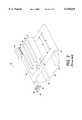
- FIG. 4illustrates a single pagewidth print bar of the present invention including an optical reader.
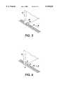
- FIG. 5illustrates one example of a reader/light source of the present invention.
- FIG. 6illustrates another example of a reader/light source of the present invention.
- FIG. 7illustrates one example of a plan view of a belt tracking fiducial marking system.
- FIG. 1illustrates a schematic elevational view of a liquid ink printer 10, for instance, an ink jet printer.
- the liquid ink printer 10includes an input tray 12 containing sheets of a recording medium 14 to be printed upon by the printer 10. Single sheets of the recording medium 14 are removed from the input tray 12 by a pickup roller 16 and fed by feed rollers 18 to a transport mechanism 20.
- the transport mechanism 20moves the sheet by a feed belt or belts 22 driven by rollers 24 beneath a liquid ink printbar assembly 26.
- the belt 22can include a plurality of apertures through which a vacuum is applied with a vacuum applicator(not shown) to hold the sheet to the belt.
- the beltcan also be an electrostatic belt by which the sheet is held electrostatically.
- the printbar assembly 26includes one or more pagewidth printbars 28 supported in a printing position by a printhead support (not shown) in a confronting relation with the belt 22. During printing, the pagewidth printbars 28 deposit liquid ink on the recording medium 14 as it is carried by the belt 22 beneath the plurality of printbars 28.
- Each of the pagewidth printbars 28includes an array of print nozzles, for instance, staggered or linear arrays, having a length sufficient to deposit ink in a printzone across the width of the recording medium 14. Such an array can be formed according to the techniques described, for example, in U.S. Pat. No. 5,221,397 the contents of which are hereby incorporated by reference.
- the printbar assembly 26also includes an ink supply either attached to the printhead support or coupled to the pagewidth printheads through appropriate supply tubing.
- the recording medium 14is then carried by the belt 22 through a dryer 32 for drying the liquid ink thereon.
- the dryer 32can be a microwave dryer or other known types of dryers generating sufficient heat energy to dry the liquid ink which has been deposited upon the recording medium 14. If, however, the dryer 32 is a microwave dryer, the belt 22 is preferably made of a material substantially transparent to microwave power and having a relatively low dielectric constant. After the sheet is substantially dry, the sheet is deposited in an output tray 33.
- ink specially formulated to be heated by microwave poweris preferably used.
- Such inkmay include compounds designed to couple with the microwave power for increasing the amount of heat conducted thereby.
- One such compoundis an ionic compound at least partially ionizable in the liquid vehicle.
- a controller 34controls the operation of the transport mechanism 20, which includes the pickup roller 16, the feed roller 18 and the drive rollers 24. In addition, the controller 34 controls the movement of the printbar assembly 26, printing by the printbars 28, and operation of the dryer 32, as would be understood by one skilled in the art.
- the controller 34can also include a plurality of individual controllers, such as microprocessors or other known devices dedicated to perform a particular function.
- An image input device 35such as a personal computer, transmits image information to the controller 34.
- the printbar assembly 26which is movable in the directions of an arrow 36, is moved away from the belt 22 such that a capping assembly 38, movable in the directions of the arrow 40, is moved beneath the printbar assembly 26 for capping thereof.
- a capping assembly 38movable in the directions of the arrow 40
- the cap assembly 38includes one or more of the capping gaskets 42 which engage or contact the page width printbars on an area surrounding one or more of the printbars to thereby seal the printbar nozzles from exposure to air.
- Suitable capping elementsinclude those described later herein or those which compress to make a satisfactory seal. This substantially airtight seal prevents the ink contained in the nozzles from drying out to thereby prevent clogging of the individual printbar nozzles.
- the ink jet printer 10includes a maintenance assembly described in the application to Anderson et al.
- the maintenance assemblyincludes a wet wiper nozzle for wiping the front face of the printhead assemblies as well as a vacuum wipe which follows the wet wipe nozzle as it moves along the front face to vacuum any contaminants from the front face including dried ink as well as paper fibers.
- the printer 49includes a first pagewidth print bar 50, a second pagewidth print bar 52, a third pagewidth print bar 54, and a fourth pagewidth print bar 56.
- Each of the print barsdeposits liquid ink upon a recording medium 58 which has a recording medium width A which is measured perpendicularly to a sheet advance direction 60.
- Each of the pagewidth print barsincludes a length sufficient to deposit a single line of information across the width A.
- each of the page width print barsdeposits one of a plurality of inks which include cyan, magenta, yellow and black.
- a rotary encoder 62enables printing at selected locations on the recording medium 58 to generate an image responsive to pixel information which is transmitted to the printheads through the controller 34.
- the rotary encoder 62includes an encoder reader 64 which is coupled to the controller 34 to transmit belt position information to the controller through a cable 66.
- a motor 68is used to drive the belt 22 in the direction 60.
- the drive rollers 24can also suffer from run out errors. Both of these disadvantages result in timing errors occurring between the actual belt position beneath the print bars and the encoder fiducial marks.
- a print-on-demand systemsuch as a thermal ink jet printer, such errors show up as banding, or hue shifts in a color system.
- the distance between print barsis determined by counting the encoder clock ticks between bars.
- Such a systemtherefore, not only suffers from inaccuracies of the rotary encoder, the encoder reader, but can also suffer from the certain inaccuracies resulting from counting encoder clock ticks between bars.
- FIG. 3shows the printer 10 of the present invention, including a first collinear print bar with an optical reader 71, a second collinear print bar 72, a third collinear print bar 74, and a fourth collinear print bar 76.
- Each of the print barsincludes an optical reader 80 which is attached to one end of each of the print bar support substrates 82.
- Adjacent to the optical readers 80, on each of the print bars,is a plurality of thermal ink jet printhead dies 84, each of which deposits ink under control of the controller 34 responsive to pixel image data received from the personal computer 35 or other known image input devices.
- each of the optical readers 80receives light from a respective one of a plurality of light sources 86, the light being transmitted through the belt 22 which is semi-transparent, in one embodiment, at least in the portion of the belt including a plurality of fiducial marks 88.
- the fiducial marks 88are located directly on the belt 22 at a pre-determined spacing such that the location of the recording sheet 58 can be accurately determined when passing by each of the print bars.
- the light sourcesmay be located at another side of the belt than the optical readers or may be located at the same side as the optical readers.
- the present inventionprovides a highly accurate recording system since the fiducial marks are located directly on the belt and the optical readers 80 are mounted directly on the print bar. While a single optical reader could be mounted on a single one of the printbars in a lower cost, less precise printing system, it is preferred that each of the print bars includes an optical reader. By mounting each of the individual readers on a print bar, such that the print bar is an integral reader/die print bar, the registration requirements necessary in mounting the print bars in such a system are relaxed since a unique encoder timing signal can be generated for each bar.
- FIG. 4illustrates the print bar 71 including the substrate 82 which acts as a heat sink as well as a substantially planar mounting surface for mounting of the thermal ink jet printhead dies 84 and the optical reader 80.
- the substrate 82due to the positional requirements of the printhead dies 84, includes a substantially planar surface at the mounting area of the printhead dies reader such that the mounting surface varies approximately no more than plus or minus 10-15 microns. Consequently, the optical reader 80, which is mounted on a surface 90 of the substrate 82, is properly aligned with the array of ink jet nozzles also mounted thereon.
- each of the substrates 82includes its own optical reader, each of the print bars generates its own positional signal which is highly accurate.
- the optical readers 80could comprise a simple photodiode, a photo transistor, an amorphous silicon array, including an array of light sensing optical readers, or a charge coupled device (CCD) array. Since the optical readers receive light from the light sources 86, and each of the light sources 86 is dedicated to the generation of a sufficient amount of light for sensing by the readers 80, wider latitude is granted in the selection of the type of light sources which can be used. For instance, if the composition of the belt material is limited due to being selected according to system constraints including to withstand microwave drying in the microwave dryer 32, the light sources 86 can be appropriately selected to generate sufficient light for reading by the optical readers 80. As such, the optical reader/light source combination is not a restrictive design. For instance, each of the light sources 86 can include a halogen lamp. In addition, a single light source may be used to generate light for all of the optical readers.
- Each of the print barsincludes an ink manifold, such as an ink manifold 92, illustrated in part, for the print bar 71, each of which supplies ink to the associated printhead dies.
- the ink manifold 92is typically connected to an ink container which is located away from the print bar by flexible tubing.
- a reflective optical reader systemcan be used as illustrated in FIG. 5 and in FIG. 6.
- the reader systemincludes a light source 89 which is coupled to the optical reader 80.
- the light source 89directs light towards the belt 22 and the markings 88 where it is reflected back to the reader 80 for the generation of the belt position signals.
- the reader 80is located closest to the substrate as illustrated.
- a reflective optical reader system 91is illustrated which includes a light source 93 and an optical reader 95 in a package attached to the substrate 82.
- the light source as well as the optical readermay also be single devices each individually mounted to the substrate 82.
- Light sourcesinclude a diode array or an incandescent light source. Emitter/receiver units are also possible.
- fiducial marks 88 of FIG. 3 and 4are aligned perpendicularly to the process direction 60
- another fiducial mark 94can be arranged parallel to the process direction 60, to intersect each of the fiducial marks 88 located perpendicularly to the process direction 60.
- the fiducial mark 94can also be considered a circumferential line since it is located throughout the belt 22.
- the optical readers 80would include a linear array of light receptors preferably embodied on an amorphous silicon array.
- the optical readertransmits a signal to the controller 34 such that printing of the image can be compensated. For instance, if the optical reader determines that the belt has moved in the direction perpendicular to the process direction 60 by an amount of 3 pixels, for instance, then the controller would translate the image information a distance of 3 nozzles to compensate.
- the present inventionalso compensates for belt wobble the side to side movement of the belt, by providing a print bar which includes additional nozzles or printhead dies such that the image on the recording medium is complete. For instance, if it is determined that in a typical recording medium 58, the print bars must cover a portion of the recording medium B to complete an image, and if a nominal amount of belt wobble is pre-determined according to various known parameters such as belt composition, tolerance studies or empirical evaluation then the print bars 71, 72, 74, and 76 would include additional nozzles determined as a function of the pre-determined belt wobble to account for the amount of belt wobble. In this way, images are accurately reproduced. For instance, as illustrated in FIG. 3, a printhead die 96, or a portion thereof, and a printhead die 98, or a portion thereof, include nozzles which would not be necessary with a less sophisticated printer.
- the present inventionincludes the maintenance device 42 which is used to apply a wetting agent, with a wetting nozzle, to the front of the printhead nozzles as well as to the optical reader.
- the present systemincludes a vacuum system, including a vacuum nozzle, to clean the printbar front face and the optical readers. Such a system is described in U.S. patent application Ser. No. 08/566,472 to Anderson et al.
- the present inventionis also useful as an automatic alignment system when the printhead bars are aligned during the manufacturing process. Since the belt 22 is new and has not suffered any distortion from repeated use, the fiducial marks 88 as well as the fiducial line 94 can act as highly accurate positioning markers for alignment of the bars. In this way, the print bar/belt/alignment system is accurately aligned with respect to one another and does not require additional manufacturing alignments which might be required in other systems where the print bar does not include an integral optical reader aligned with the printhead dies.
- the present inventionis not limited to the embodiments shown, but is applicable to any liquid ink print engine which is used for printing images on recording mediums including copiers.
- the printheadcould include not only a sideshooter type of printbar as described but can also include roofshooter types of printbars. Accordingly, it is intended to embrace all such alternatives, modifications and variations that fall within the spirit and broad scope of the appended claims.
Landscapes
- Engineering & Computer Science (AREA)
- Mechanical Engineering (AREA)
- Ink Jet (AREA)
Abstract
Description
Claims (22)
Priority Applications (2)
| Application Number | Priority Date | Filing Date | Title |
|---|---|---|---|
| US09/004,763US6155669A (en) | 1998-01-08 | 1998-01-08 | Pagewidth ink jet printer including a printbar mounted encoding system |
| JP11000417AJPH11245383A (en) | 1998-01-08 | 1999-01-05 | Liquid ink printer |
Applications Claiming Priority (1)
| Application Number | Priority Date | Filing Date | Title |
|---|---|---|---|
| US09/004,763US6155669A (en) | 1998-01-08 | 1998-01-08 | Pagewidth ink jet printer including a printbar mounted encoding system |
Publications (1)
| Publication Number | Publication Date |
|---|---|
| US6155669Atrue US6155669A (en) | 2000-12-05 |
Family
ID=21712410
Family Applications (1)
| Application Number | Title | Priority Date | Filing Date |
|---|---|---|---|
| US09/004,763Expired - LifetimeUS6155669A (en) | 1998-01-08 | 1998-01-08 | Pagewidth ink jet printer including a printbar mounted encoding system |
Country Status (2)
| Country | Link |
|---|---|
| US (1) | US6155669A (en) |
| JP (1) | JPH11245383A (en) |
Cited By (42)
| Publication number | Priority date | Publication date | Assignee | Title |
|---|---|---|---|---|
| US6375296B1 (en)* | 2001-06-29 | 2002-04-23 | Hewlett-Packard Company | Printing system and method for continuous web print medium |
| US6409329B1 (en)* | 2001-01-30 | 2002-06-25 | Xerox Corporation | Method and device to prevent foreign metallic object damage in fluid ejection systems using microwave dryers |
| US6412907B1 (en) | 2001-01-24 | 2002-07-02 | Xerox Corporation | Stitching and color registration control for multi-scan printing |
| US6439699B1 (en)* | 1998-10-16 | 2002-08-27 | Silverbrook Research Pty Ltd | Ink supply unit structure |
| US20030063908A1 (en)* | 1998-11-09 | 2003-04-03 | Kia Silverbrook | Image processor with integrated printing |
| WO2003029012A1 (en)* | 2001-09-28 | 2003-04-10 | Silverbrook Research Pty Ltd | A keyboard |
| US20030081227A1 (en)* | 2001-10-30 | 2003-05-01 | Williams Kenneth R. | Multiple print unit configurations |
| US20030128253A1 (en)* | 2000-07-26 | 2003-07-10 | Olympus Optical Co., Ltd. | Printer |
| US6663206B2 (en) | 2002-01-16 | 2003-12-16 | Xerox Corporation | Systems and method for masking stitch errors |
| WO2004033210A2 (en) | 2002-10-10 | 2004-04-22 | Olivetti I-Jet S.P.A. | Parallel ink jet printing device and manufacturing process |
| US20040080564A1 (en)* | 2002-10-24 | 2004-04-29 | Maher Edward P. | Printing device and method |
| US20040135076A1 (en)* | 2003-01-15 | 2004-07-15 | Xerox Corporation | Method and apparatus for obtaining a high quality sine wave from an analog quadrature encoder |
| US20040189736A1 (en)* | 2003-03-27 | 2004-09-30 | Maher Edward P. | Printing device and method for servicing same |
| US20040233267A1 (en)* | 1998-11-09 | 2004-11-25 | Kia Silverbrook | Image recordal and generation apparatus |
| US20040247362A1 (en)* | 1997-07-15 | 2004-12-09 | King Tobin Allen | Keyboard |
| EP1522414A1 (en) | 2003-10-10 | 2005-04-13 | Hewlett-Packard Development Company, L.P. | MultiColor-Printers And Methods Of Printing Images |
| US20050078015A1 (en)* | 2003-10-10 | 2005-04-14 | Jordi Ferran | Encoding system |
| US20050078133A1 (en)* | 2003-10-10 | 2005-04-14 | Pep-Lluis Molinet | Compensation of lateral position changes in printing |
| US20050163552A1 (en)* | 2004-01-28 | 2005-07-28 | Samsung Electronics Co., Ltd. | Printing method and image forming apparatus for performing the same |
| US20050219557A1 (en)* | 2004-03-30 | 2005-10-06 | Yoshikazu Koike | Printer |
| US20050219292A1 (en)* | 2004-03-30 | 2005-10-06 | Yoshikazu Koike | Printer |
| US20050253920A1 (en)* | 2004-05-11 | 2005-11-17 | Eiki Yoshimizu | Recording paper conveying apparatus, inkjet recording apparatus, and method for controlling conveyance of recording paper conveying apparatus |
| US20060033764A1 (en)* | 2004-08-06 | 2006-02-16 | Canon Finetech Inc. | Printing apparatus, printing system, printing method, and program |
| US7014307B2 (en) | 1998-11-09 | 2006-03-21 | Silverbrook Research Pty Ltd | Printing unit for an image recordal and generation apparatus |
| EP1375167A3 (en)* | 2002-06-28 | 2006-05-24 | Fuji Photo Film Co., Ltd. | Inkjet recording device and recording method |
| US20060119651A1 (en)* | 2004-12-06 | 2006-06-08 | Berry Norman M | Capping system for inkjet printhead assembly |
| WO2006084614A3 (en)* | 2005-02-08 | 2006-11-30 | Durst Phototechnik Ag | Inkjet printing device and method for printing multi-coloured images |
| US20070274759A1 (en)* | 2005-12-05 | 2007-11-29 | Silverbrook Research Pty Ltd | Printer Having Easily Mountable Media Transport Arrangement |
| US20080074450A1 (en)* | 2006-09-27 | 2008-03-27 | Fujifilm Corporation | Image forming apparatus and image forming method |
| US20100097620A1 (en)* | 2008-10-16 | 2010-04-22 | Xerox Corporation | In-line image geometrics measurment via local sampling on sheets in a printing system |
| US20100149242A1 (en)* | 2008-12-12 | 2010-06-17 | Ricoh Company, Ltd. | Image forming apparatus |
| US20100283817A1 (en)* | 2004-01-21 | 2010-11-11 | Silverbrook Research Pty Ltd | Printer print engine with cradled cartridge unit |
| EP2692534A1 (en)* | 2012-08-02 | 2014-02-05 | Prografix Sp. z o.o. | Continuous stream inkjet printing system |
| US20150165785A1 (en)* | 2013-12-18 | 2015-06-18 | Xerox Corporation | Autofocus led print head mechanism |
| US9168748B2 (en) | 2012-09-20 | 2015-10-27 | Hewlett-Packard Development Company, L.P. | Nozzle arrays |
| JP2017019624A (en)* | 2015-07-10 | 2017-01-26 | セイコーエプソン株式会社 | Printer |
| US9862209B2 (en)* | 2015-07-17 | 2018-01-09 | Seiko Epson Corporation | Printing apparatus |
| US10422665B2 (en) | 2014-10-28 | 2019-09-24 | Hewlett-Packard Development Company, L.P. | Adjusting emulated encoder frequencies |
| EP3099478B1 (en)* | 2014-01-30 | 2020-04-15 | Sacmi Cooperativa Meccanici Imola Societa' Cooperativa | A method for manufacture of a continuous press belt for ceramic slabs having a structured surface |
| EP3057785B1 (en)* | 2013-10-17 | 2022-08-17 | Berndorf Band GmbH | Method for applying a mask-shaped coating to an endless belt |
| US20230054376A1 (en)* | 2015-04-15 | 2023-02-23 | Robert A. Flitsch | Methods, materials and apparatus for mobile additive manufacturing of advanced structures and roadways |
| CN117341358A (en)* | 2012-03-05 | 2024-01-05 | 兰达公司 | Control apparatus and method for digital printing system |
Families Citing this family (46)
| Publication number | Priority date | Publication date | Assignee | Title |
|---|---|---|---|---|
| JP4622400B2 (en)* | 2004-09-08 | 2011-02-02 | 富士ゼロックス株式会社 | Image recording device |
| JP4688188B2 (en)* | 2005-06-17 | 2011-05-25 | 株式会社リコー | Image forming apparatus |
| JP5103869B2 (en)* | 2006-10-31 | 2012-12-19 | 富士ゼロックス株式会社 | Droplet discharge device |
| JP4265655B2 (en) | 2007-01-12 | 2009-05-20 | セイコーエプソン株式会社 | Inkjet printer |
| JP5003457B2 (en) | 2007-03-23 | 2012-08-15 | セイコーエプソン株式会社 | Printing device |
| JP5286722B2 (en)* | 2007-09-13 | 2013-09-11 | 富士ゼロックス株式会社 | Image forming apparatus |
| JP2009078376A (en) | 2007-09-25 | 2009-04-16 | Seiko Epson Corp | Image forming apparatus and pulse generation method |
| JP5228446B2 (en)* | 2007-11-06 | 2013-07-03 | セイコーエプソン株式会社 | Liquid ejecting apparatus and method for controlling liquid ejecting apparatus |
| JP2009113313A (en)* | 2007-11-06 | 2009-05-28 | Seiko Epson Corp | Liquid ejecting apparatus and method for controlling liquid ejecting apparatus |
| JP5024081B2 (en) | 2008-01-31 | 2012-09-12 | セイコーエプソン株式会社 | Recording system and recording apparatus |
| JP2009248502A (en) | 2008-04-09 | 2009-10-29 | Seiko Epson Corp | Pulse signal generating device, transport device, image forming apparatus, and pulse generating method |
| JP2009249166A (en) | 2008-04-10 | 2009-10-29 | Seiko Epson Corp | Pulse signal generating device, transport device, image forming apparatus and pulse generating method |
| JP6437312B2 (en) | 2012-03-05 | 2018-12-12 | ランダ コーポレイション リミテッド | Digital printing process |
| US11104123B2 (en) | 2012-03-05 | 2021-08-31 | Landa Corporation Ltd. | Digital printing system |
| US9498946B2 (en) | 2012-03-05 | 2016-11-22 | Landa Corporation Ltd. | Apparatus and method for control or monitoring of a printing system |
| US11106161B2 (en) | 2012-03-05 | 2021-08-31 | Landa Corporation Ltd. | Intermediate transfer members for use with indirect printing systems and protonatable intermediate transfer members for use with indirect printing systems |
| US9643403B2 (en) | 2012-03-05 | 2017-05-09 | Landa Corporation Ltd. | Printing system |
| HK1204640A1 (en) | 2012-03-05 | 2015-11-27 | Landa Corporation Ltd. | Ink film constructions |
| EP2825486B1 (en) | 2012-03-15 | 2019-01-02 | Landa Corporation Ltd. | Endless flexible belt for a printing system |
| GB201401173D0 (en) | 2013-09-11 | 2014-03-12 | Landa Corp Ltd | Ink formulations and film constructions thereof |
| JP6247091B2 (en)* | 2013-12-26 | 2017-12-13 | 株式会社Screenホールディングス | Printing position correction method for printing apparatus and printing apparatus |
| GB2536489B (en) | 2015-03-20 | 2018-08-29 | Landa Corporation Ltd | Indirect printing system |
| GB2537813A (en) | 2015-04-14 | 2016-11-02 | Landa Corp Ltd | Apparatus for threading an intermediate transfer member of a printing system |
| EP3437871A4 (en)* | 2016-03-28 | 2019-04-03 | Konica Minolta, Inc. | Inkjet recording device and recording control method for inkjet recording device |
| JP6980704B2 (en) | 2016-05-30 | 2021-12-15 | ランダ コーポレイション リミテッド | Digital printing process |
| US10933661B2 (en) | 2016-05-30 | 2021-03-02 | Landa Corporation Ltd. | Digital printing process |
| GB201609463D0 (en) | 2016-05-30 | 2016-07-13 | Landa Labs 2012 Ltd | Method of manufacturing a multi-layer article |
| JP6836134B2 (en)* | 2016-11-02 | 2021-02-24 | セイコーエプソン株式会社 | Printing device and adjustment method of printing device |
| US10926532B2 (en) | 2017-10-19 | 2021-02-23 | Landa Corporation Ltd. | Endless flexible belt for a printing system |
| US11267239B2 (en) | 2017-11-19 | 2022-03-08 | Landa Corporation Ltd. | Digital printing system |
| US11511536B2 (en) | 2017-11-27 | 2022-11-29 | Landa Corporation Ltd. | Calibration of runout error in a digital printing system |
| US11707943B2 (en) | 2017-12-06 | 2023-07-25 | Landa Corporation Ltd. | Method and apparatus for digital printing |
| WO2019111223A1 (en) | 2017-12-07 | 2019-06-13 | Landa Corporation Ltd. | Digital printing process and method |
| JP7016481B2 (en)* | 2018-03-15 | 2022-02-07 | 株式会社リコー | Device that discharges liquid |
| CN117885446A (en) | 2018-06-26 | 2024-04-16 | 兰达公司 | Intermediate transmission components of digital printing systems |
| US10994528B1 (en) | 2018-08-02 | 2021-05-04 | Landa Corporation Ltd. | Digital printing system with flexible intermediate transfer member |
| US12001902B2 (en) | 2018-08-13 | 2024-06-04 | Landa Corporation Ltd. | Correcting distortions in digital printing by implanting dummy pixels in a digital image |
| US10635954B2 (en)* | 2018-10-02 | 2020-04-28 | Xerox Corporation | Dot clock signal generation for operating ejectors in multiple color stations in a substrate printer |
| WO2020075012A1 (en) | 2018-10-08 | 2020-04-16 | Landa Corporation Ltd. | Friction reduction means for printing systems and method |
| CN116080260A (en) | 2018-12-24 | 2023-05-09 | 兰达公司 | Digital printing system and method |
| JP7180454B2 (en)* | 2019-03-06 | 2022-11-30 | 株式会社リコー | LIQUID EJECTING APPARATUS AND IMAGE FORMING APPARATUS |
| US12358277B2 (en) | 2019-03-31 | 2025-07-15 | Landa Corporation Ltd. | Systems and methods for preventing or minimizing printing defects in printing processes |
| JP7685995B2 (en) | 2019-11-25 | 2025-05-30 | ランダ コーポレイション リミテッド | Drying of ink in digital printing using infrared radiation absorbed by particles embedded within an ITM |
| US11321028B2 (en) | 2019-12-11 | 2022-05-03 | Landa Corporation Ltd. | Correcting registration errors in digital printing |
| JP7657229B2 (en) | 2019-12-29 | 2025-04-04 | ランダ コーポレイション リミテッド | Printing method and system |
| EP4264377A4 (en) | 2021-02-02 | 2024-11-13 | Landa Corporation Ltd. | REDUCING DISTORTIONS IN PRINTED IMAGES |
Citations (4)
| Publication number | Priority date | Publication date | Assignee | Title |
|---|---|---|---|---|
| US4912491A (en)* | 1987-05-30 | 1990-03-27 | Canon Kabushiki Kaisha | Apparatus for forming superimposed images |
| US5040003A (en)* | 1990-06-04 | 1991-08-13 | Eastman Kodak Company | Method and apparatus for recording color with plural printheads |
| US5220346A (en)* | 1992-02-03 | 1993-06-15 | Xerox Corporation | Printing processes with microwave drying |
| US5394223A (en)* | 1992-08-17 | 1995-02-28 | Xerox Corporation | Apparatus for image registration |
- 1998
- 1998-01-08USUS09/004,763patent/US6155669A/ennot_activeExpired - Lifetime
- 1999
- 1999-01-05JPJP11000417Apatent/JPH11245383A/enactivePending
Patent Citations (4)
| Publication number | Priority date | Publication date | Assignee | Title |
|---|---|---|---|---|
| US4912491A (en)* | 1987-05-30 | 1990-03-27 | Canon Kabushiki Kaisha | Apparatus for forming superimposed images |
| US5040003A (en)* | 1990-06-04 | 1991-08-13 | Eastman Kodak Company | Method and apparatus for recording color with plural printheads |
| US5220346A (en)* | 1992-02-03 | 1993-06-15 | Xerox Corporation | Printing processes with microwave drying |
| US5394223A (en)* | 1992-08-17 | 1995-02-28 | Xerox Corporation | Apparatus for image registration |
Cited By (126)
| Publication number | Priority date | Publication date | Assignee | Title |
|---|---|---|---|---|
| US6986613B2 (en) | 1997-07-15 | 2006-01-17 | Silverbrook Research Pty Ltd | Keyboard |
| US6921221B2 (en) | 1997-07-15 | 2005-07-26 | Silverbrook Research Pty Ltd | Combination keyboard and printer apparatus |
| US6988841B2 (en) | 1997-07-15 | 2006-01-24 | Silverbrook Research Pty Ltd. | Pagewidth printer that includes a computer-connectable keyboard |
| US20050232675A1 (en)* | 1997-07-15 | 2005-10-20 | Silverbrook Research Pty Ltd | Printer within a computer keyboard |
| US20050232676A1 (en)* | 1997-07-15 | 2005-10-20 | Silverbrook Research Pty Ltd. | Computer system having integrated printer and keyboard |
| US7217048B2 (en) | 1997-07-15 | 2007-05-15 | Silverbrook Research Pty Ltd | Pagewidth printer and computer keyboard combination |
| US20050226667A1 (en)* | 1997-07-15 | 2005-10-13 | Silverbrook Research Pty Ltd. | Pagewidth printer and computer keyboard combination |
| US20050226668A1 (en)* | 1997-07-15 | 2005-10-13 | Silverbrook Research Pty Ltd | Keyboard for a computer system |
| US6953295B2 (en) | 1997-07-15 | 2005-10-11 | Silverbrook Research Pty Ltd | Small footprint computer system |
| US6641315B2 (en) | 1997-07-15 | 2003-11-04 | Silverbrook Research Pty Ltd | Keyboard |
| US7367729B2 (en) | 1997-07-15 | 2008-05-06 | Silverbrook Research Pty Ltd | Printer within a computer keyboard |
| US7517164B2 (en) | 1997-07-15 | 2009-04-14 | Silverbrook Research Pty Ltd | Computer keyboard with a planar member and endless belt feed mechanism |
| US20040062588A1 (en)* | 1997-07-15 | 2004-04-01 | King Tobin Allen | Keyboard that incorporates a printing mechanism |
| US20070292185A1 (en)* | 1997-07-15 | 2007-12-20 | Silverbrook Research Pty Ltd | Computer Keyboard With Internal Printer |
| US6923583B2 (en) | 1997-07-15 | 2005-08-02 | Silverbrook Research Pty Ltd | Computer Keyboard with integral printer |
| US20080019756A1 (en)* | 1997-07-15 | 2008-01-24 | Silverbrook Research Pty Ltd | Computer keyboard with a planar member and endless belt feed mechanism |
| US6786661B2 (en) | 1997-07-15 | 2004-09-07 | Silverbrook Research Pty Ltd. | Keyboard that incorporates a printing mechanism |
| US7845869B2 (en) | 1997-07-15 | 2010-12-07 | Silverbrook Research Pty Ltd | Computer keyboard with internal printer |
| US6808325B2 (en) | 1997-07-15 | 2004-10-26 | Silverbrook Research Pty Ltd | Keyboard with an internal printer |
| US7270492B2 (en) | 1997-07-15 | 2007-09-18 | Silverbrook Research Pty Ltd | Computer system having integrated printer and keyboard |
| US6918707B2 (en) | 1997-07-15 | 2005-07-19 | Silverbrook Research Pty Ltd | Keyboard printer print media transport assembly |
| US20040247362A1 (en)* | 1997-07-15 | 2004-12-09 | King Tobin Allen | Keyboard |
| US7278796B2 (en) | 1997-07-15 | 2007-10-09 | Silverbrook Research Pty Ltd | Keyboard for a computer system |
| US20050041086A1 (en)* | 1997-07-15 | 2005-02-24 | King Tobin Allen | Pagewidth printer that includes a computer-connectable keyboard |
| US20050058489A1 (en)* | 1997-07-15 | 2005-03-17 | King Tobin Allen | Small footprint computer system |
| US20050058490A1 (en)* | 1997-07-15 | 2005-03-17 | King Tobin Allen | Computer keyboard with integral printer |
| US20050058491A1 (en)* | 1997-07-15 | 2005-03-17 | King Tobin Allen | Keyboard printer print media transport assembly |
| US7077588B2 (en) | 1997-07-15 | 2006-07-18 | Silverbrook Research Pty Ltd | Printer and keyboard combination |
| US20050063758A1 (en)* | 1997-07-15 | 2005-03-24 | King Tobin Allen | Combination keyboard and printer apparatus |
| US20050063759A1 (en)* | 1997-07-15 | 2005-03-24 | King Tobin Allen | Printer and keyboard combination |
| US6439699B1 (en)* | 1998-10-16 | 2002-08-27 | Silverbrook Research Pty Ltd | Ink supply unit structure |
| US7154580B2 (en) | 1998-11-09 | 2006-12-26 | Silverbrook Research Pty Ltd | Image recordal and generation apparatus |
| US7695082B2 (en) | 1998-11-09 | 2010-04-13 | Silverbrook Research Pty Ltd | PCMCIA printing device |
| US20040233267A1 (en)* | 1998-11-09 | 2004-11-25 | Kia Silverbrook | Image recordal and generation apparatus |
| US20060158490A1 (en)* | 1998-11-09 | 2006-07-20 | Silverbrook Research Pty Ltd | Inkjet printer for digital camera |
| US6906778B2 (en) | 1998-11-09 | 2005-06-14 | Silverbrook Research Pty Ltd | Image recordal and generation apparatus |
| US7014307B2 (en) | 1998-11-09 | 2006-03-21 | Silverbrook Research Pty Ltd | Printing unit for an image recordal and generation apparatus |
| US7271829B2 (en) | 1998-11-09 | 2007-09-18 | Silverbrook Research Pty Ltd | Inkjet printer for digital camera |
| US20070103537A1 (en)* | 1998-11-09 | 2007-05-10 | Silverbrook Research Pty Ltd | PCMCIA Printing device |
| US7289727B2 (en) | 1998-11-09 | 2007-10-30 | Silverbrook Research Pty Ltd | Image processor with integrated printing |
| US7147294B2 (en) | 1998-11-09 | 2006-12-12 | Silverbrook Research Pty Ltd | PCMCIA printer |
| US20060250475A9 (en)* | 1998-11-09 | 2006-11-09 | Kia Silverbrook | Image recordal and generation apparatus |
| US20070058969A9 (en)* | 1998-11-09 | 2007-03-15 | Kia Silverbrook | Image processor with integrated printing |
| US20050078160A1 (en)* | 1998-11-09 | 2005-04-14 | Kia Silverbrook | PCMCIA printer |
| US20030063908A1 (en)* | 1998-11-09 | 2003-04-03 | Kia Silverbrook | Image processor with integrated printing |
| US6672705B2 (en)* | 2000-07-26 | 2004-01-06 | Olympus Optical Co., Ltd. | Printer |
| US20030128253A1 (en)* | 2000-07-26 | 2003-07-10 | Olympus Optical Co., Ltd. | Printer |
| US6964468B2 (en) | 2000-07-26 | 2005-11-15 | Olympus Optical Co., Ltd. | Printer |
| EP1226954A3 (en)* | 2001-01-24 | 2003-10-22 | Xerox Corporation | Stitching and color registration control for multi-scan printing |
| US6412907B1 (en) | 2001-01-24 | 2002-07-02 | Xerox Corporation | Stitching and color registration control for multi-scan printing |
| US6409329B1 (en)* | 2001-01-30 | 2002-06-25 | Xerox Corporation | Method and device to prevent foreign metallic object damage in fluid ejection systems using microwave dryers |
| US6375296B1 (en)* | 2001-06-29 | 2002-04-23 | Hewlett-Packard Company | Printing system and method for continuous web print medium |
| AU2002325070B2 (en)* | 2001-09-28 | 2005-10-27 | Silverbrook Research Pty Ltd | A keyboard |
| WO2003029012A1 (en)* | 2001-09-28 | 2003-04-10 | Silverbrook Research Pty Ltd | A keyboard |
| US7575315B2 (en)* | 2001-10-30 | 2009-08-18 | Hewlett-Packard Development Company, L.P. | Multiple print unit configurations |
| US20030081227A1 (en)* | 2001-10-30 | 2003-05-01 | Williams Kenneth R. | Multiple print unit configurations |
| US6663206B2 (en) | 2002-01-16 | 2003-12-16 | Xerox Corporation | Systems and method for masking stitch errors |
| EP1375167A3 (en)* | 2002-06-28 | 2006-05-24 | Fuji Photo Film Co., Ltd. | Inkjet recording device and recording method |
| CN1305679C (en)* | 2002-06-28 | 2007-03-21 | 富士胶片株式会社 | Ink-jet recording device and recording method |
| WO2004033210A3 (en)* | 2002-10-10 | 2004-12-29 | Olivetti I Jet Spa | Parallel ink jet printing device and manufacturing process |
| WO2004033210A2 (en) | 2002-10-10 | 2004-04-22 | Olivetti I-Jet S.P.A. | Parallel ink jet printing device and manufacturing process |
| US20070195121A1 (en)* | 2002-10-10 | 2007-08-23 | Telecom Italia S.P.A. | Parallel ink jet printing device and relative manufacturing |
| US8393710B2 (en) | 2002-10-10 | 2013-03-12 | Telecom Italia S.P.A. | Parallel ink jet printing device and relative manufacturing |
| US7984978B2 (en) | 2002-10-10 | 2011-07-26 | Telecom Italia S.P.A. | Parallel ink jet printing device and relative manufacturing |
| US6814421B2 (en) | 2002-10-24 | 2004-11-09 | Hewlett-Packard Development Company, L.P. | Printing device and method |
| US20040080564A1 (en)* | 2002-10-24 | 2004-04-29 | Maher Edward P. | Printing device and method |
| US20040135076A1 (en)* | 2003-01-15 | 2004-07-15 | Xerox Corporation | Method and apparatus for obtaining a high quality sine wave from an analog quadrature encoder |
| US20040189736A1 (en)* | 2003-03-27 | 2004-09-30 | Maher Edward P. | Printing device and method for servicing same |
| US6869162B2 (en) | 2003-03-27 | 2005-03-22 | Hewlett-Packard Development Company, L.P. | Printing device and method for servicing same |
| EP1522414A1 (en) | 2003-10-10 | 2005-04-13 | Hewlett-Packard Development Company, L.P. | MultiColor-Printers And Methods Of Printing Images |
| US20050078137A1 (en)* | 2003-10-10 | 2005-04-14 | Femando Juan | Multi-color printer |
| US7129858B2 (en)* | 2003-10-10 | 2006-10-31 | Hewlett-Packard Development Company, L.P. | Encoding system |
| US20050078015A1 (en)* | 2003-10-10 | 2005-04-14 | Jordi Ferran | Encoding system |
| US7021738B2 (en) | 2003-10-10 | 2006-04-04 | Hewlett-Packard Development Company, L.P. | Multi-color printer |
| US6942308B2 (en) | 2003-10-10 | 2005-09-13 | Hewlett-Packard Development Company, L.P. | Compensation of lateral position changes in printing |
| US20050078133A1 (en)* | 2003-10-10 | 2005-04-14 | Pep-Lluis Molinet | Compensation of lateral position changes in printing |
| US8235502B2 (en)* | 2004-01-21 | 2012-08-07 | Zamtec Limited | Printer print engine with cradled cartridge unit |
| US20100283817A1 (en)* | 2004-01-21 | 2010-11-11 | Silverbrook Research Pty Ltd | Printer print engine with cradled cartridge unit |
| US20050163552A1 (en)* | 2004-01-28 | 2005-07-28 | Samsung Electronics Co., Ltd. | Printing method and image forming apparatus for performing the same |
| US20050219292A1 (en)* | 2004-03-30 | 2005-10-06 | Yoshikazu Koike | Printer |
| US7354128B2 (en)* | 2004-03-30 | 2008-04-08 | Seiko Epson Corporation | Printer |
| US20080024538A1 (en)* | 2004-03-30 | 2008-01-31 | Yoshikazu Koike | Printer |
| US20050219557A1 (en)* | 2004-03-30 | 2005-10-06 | Yoshikazu Koike | Printer |
| US7552991B2 (en) | 2004-03-30 | 2009-06-30 | Seiko Epson Corporation | Printer |
| US7552679B2 (en)* | 2004-03-30 | 2009-06-30 | Seiko Epson Corporation | Printer |
| US7559617B2 (en) | 2004-03-30 | 2009-07-14 | Seiko Epson Corporation | Printer |
| US7712739B2 (en)* | 2004-05-11 | 2010-05-11 | Ricoh Company, Ltd. | Conveying apparatus, inkjet recording apparatus, and method for controlling conveyance |
| US20050253920A1 (en)* | 2004-05-11 | 2005-11-17 | Eiki Yoshimizu | Recording paper conveying apparatus, inkjet recording apparatus, and method for controlling conveyance of recording paper conveying apparatus |
| US7658460B2 (en)* | 2004-08-06 | 2010-02-09 | Canon Finetech Inc. | Printing apparatus, method, and program comprising a plurality of printer units using synchronized, divided print data |
| US20060033764A1 (en)* | 2004-08-06 | 2006-02-16 | Canon Finetech Inc. | Printing apparatus, printing system, printing method, and program |
| US20100103218A1 (en)* | 2004-12-06 | 2010-04-29 | Silverbrook Research Pty Ltd | Method Of Capping Printhead Assembly |
| US20080252683A1 (en)* | 2004-12-06 | 2008-10-16 | Silverbrook Research Pty Ltd | Printer having capping system for printhead assembly |
| US7648223B2 (en) | 2004-12-06 | 2010-01-19 | Silverbrook Research Pty Ltd | Method of capping printhead assembly |
| US20060119651A1 (en)* | 2004-12-06 | 2006-06-08 | Berry Norman M | Capping system for inkjet printhead assembly |
| US20100073421A1 (en)* | 2004-12-06 | 2010-03-25 | Silverbrook Research Pty Ltd | Printer Having Duplex Printheads And Cappers |
| US20090122104A1 (en)* | 2004-12-06 | 2009-05-14 | Silverbrook Research Pty Ltd | Pagewidth Printhead Assembly Having A Capping Member Actuating Mechanism |
| US7862146B2 (en) | 2004-12-06 | 2011-01-04 | Silverbrook Research Pty Ltd | Pagewidth printhead assembly having a capping member actuating mechanism |
| US20080252684A1 (en)* | 2004-12-06 | 2008-10-16 | Silverbrook Research Pty Ltd | Method of capping printhead assembly |
| US7465015B2 (en)* | 2004-12-06 | 2008-12-16 | Silverbrook Research Pty Ltd | Capping system for inkjet printhead assembly |
| US7645023B2 (en) | 2004-12-06 | 2010-01-12 | Silverbrook Research Pty Ltd | Printer having capping system for printhead assembly |
| US8141981B2 (en) | 2005-02-08 | 2012-03-27 | Durst Phototechnik - A.G. | Inkjet printing device and method for printing multi-coloured images |
| WO2006084614A3 (en)* | 2005-02-08 | 2006-11-30 | Durst Phototechnik Ag | Inkjet printing device and method for printing multi-coloured images |
| US8764148B2 (en) | 2005-02-08 | 2014-07-01 | Durst Phototechnik—A.G. | Inkjet printing device and method for printing multi-colored images |
| US20090213157A1 (en)* | 2005-02-08 | 2009-08-27 | Franz Obertegger | Inkjet Printing Device and Method for Printing Multi-Coloured Images |
| CN102029791B (en)* | 2005-02-08 | 2013-04-03 | 得士影像技术股份公司 | Inkjet printing device and method for printing multi-coloured images |
| US7914217B2 (en) | 2005-12-05 | 2011-03-29 | Kia Silverbrook | Printer having easily mountable media transport arrangement |
| US20070274759A1 (en)* | 2005-12-05 | 2007-11-29 | Silverbrook Research Pty Ltd | Printer Having Easily Mountable Media Transport Arrangement |
| US20080074450A1 (en)* | 2006-09-27 | 2008-03-27 | Fujifilm Corporation | Image forming apparatus and image forming method |
| US8033662B2 (en)* | 2006-09-27 | 2011-10-11 | Fujifilm Corporation | Image forming apparatus and method for preventing image deterioration due to speed variation in an imtermediate transfer body |
| US20100097620A1 (en)* | 2008-10-16 | 2010-04-22 | Xerox Corporation | In-line image geometrics measurment via local sampling on sheets in a printing system |
| US8462380B2 (en) | 2008-10-16 | 2013-06-11 | Xerox Corporation | In-line image geometrics measurement via local sampling on sheets in a printing system |
| US20100149242A1 (en)* | 2008-12-12 | 2010-06-17 | Ricoh Company, Ltd. | Image forming apparatus |
| US8267511B2 (en)* | 2008-12-12 | 2012-09-18 | Ricoh Company, Ltd. | Image forming apparatus |
| CN117341358A (en)* | 2012-03-05 | 2024-01-05 | 兰达公司 | Control apparatus and method for digital printing system |
| EP2692534A1 (en)* | 2012-08-02 | 2014-02-05 | Prografix Sp. z o.o. | Continuous stream inkjet printing system |
| US9168748B2 (en) | 2012-09-20 | 2015-10-27 | Hewlett-Packard Development Company, L.P. | Nozzle arrays |
| US9387676B2 (en) | 2012-09-20 | 2016-07-12 | Hewlett-Packard Development Company, L.P. | Nozzle arrays |
| EP3057785B1 (en)* | 2013-10-17 | 2022-08-17 | Berndorf Band GmbH | Method for applying a mask-shaped coating to an endless belt |
| US20150165785A1 (en)* | 2013-12-18 | 2015-06-18 | Xerox Corporation | Autofocus led print head mechanism |
| US9180684B2 (en)* | 2013-12-18 | 2015-11-10 | Xerox Corporation | Autofocus LED print head mechanism |
| EP3099478B1 (en)* | 2014-01-30 | 2020-04-15 | Sacmi Cooperativa Meccanici Imola Societa' Cooperativa | A method for manufacture of a continuous press belt for ceramic slabs having a structured surface |
| US10422665B2 (en) | 2014-10-28 | 2019-09-24 | Hewlett-Packard Development Company, L.P. | Adjusting emulated encoder frequencies |
| US20230054376A1 (en)* | 2015-04-15 | 2023-02-23 | Robert A. Flitsch | Methods, materials and apparatus for mobile additive manufacturing of advanced structures and roadways |
| US12291823B2 (en)* | 2015-04-15 | 2025-05-06 | Robert A. Flitsch | Methods, materials and apparatus for mobile additive manufacturing of advanced structures and roadways |
| JP2017019624A (en)* | 2015-07-10 | 2017-01-26 | セイコーエプソン株式会社 | Printer |
| US9862209B2 (en)* | 2015-07-17 | 2018-01-09 | Seiko Epson Corporation | Printing apparatus |
Also Published As
| Publication number | Publication date |
|---|---|
| JPH11245383A (en) | 1999-09-14 |
Similar Documents
| Publication | Publication Date | Title |
|---|---|---|
| US6155669A (en) | Pagewidth ink jet printer including a printbar mounted encoding system | |
| US8162428B2 (en) | System and method for compensating runout errors in a moving web printing system | |
| US8342628B2 (en) | Image forming apparatus | |
| US5719602A (en) | Controlling PWA inkjet nozzle timing as a function of media speed | |
| US8186799B2 (en) | Image forming apparatus and impact position displacement correction method | |
| US7131782B2 (en) | Paper edge sensing apparatus and method for borderless printing | |
| US8579408B2 (en) | System and method for measuring fluid drop mass with reference to test pattern image data | |
| US5757398A (en) | Liquid ink printer including a maintenance system | |
| US6224183B1 (en) | Ink-jet printing apparatus and facsimile apparatus | |
| US20090189937A1 (en) | Image forming apparatus | |
| CN102248781B (en) | Image processing system | |
| JPH07246708A (en) | Inkjet recording device | |
| US5568172A (en) | Printing method and apparatus for registering dots | |
| JPH0880609A (en) | Inkjet recording means and recording apparatus | |
| US8070250B2 (en) | Image forming apparatus | |
| EP0830944A2 (en) | Ink-jet printing device with drum head | |
| JP4599704B2 (en) | Printer and printer driving method | |
| US20070076081A1 (en) | Image-forming device | |
| US7992991B2 (en) | Image forming apparatus | |
| US6726309B2 (en) | Ink jet recording apparatus | |
| JPH0516462A (en) | Recording device | |
| JPH0994948A (en) | Inkjet printer | |
| CN1075447C (en) | Ink jet recording apparatus | |
| JP2939817B2 (en) | Ink jet recording device | |
| JP2002225374A (en) | Electronic device and recording device |
Legal Events
| Date | Code | Title | Description |
|---|---|---|---|
| AS | Assignment | Owner name:XEROX CORPORATION, CONNECTICUT Free format text:ASSIGNMENT OF ASSIGNORS INTEREST;ASSIGNORS:DONAHUE, FREDERICK A.;ANDERSON, DAVID G.;REEL/FRAME:008925/0472;SIGNING DATES FROM 19971216 TO 19971217 | |
| STCF | Information on status: patent grant | Free format text:PATENTED CASE | |
| AS | Assignment | Owner name:BANK ONE, NA, AS ADMINISTRATIVE AGENT, ILLINOIS Free format text:SECURITY INTEREST;ASSIGNOR:XEROX CORPORATION;REEL/FRAME:013153/0001 Effective date:20020621 | |
| AS | Assignment | Owner name:JPMORGAN CHASE BANK, AS COLLATERAL AGENT, TEXAS Free format text:SECURITY AGREEMENT;ASSIGNOR:XEROX CORPORATION;REEL/FRAME:015134/0476 Effective date:20030625 Owner name:JPMORGAN CHASE BANK, AS COLLATERAL AGENT,TEXAS Free format text:SECURITY AGREEMENT;ASSIGNOR:XEROX CORPORATION;REEL/FRAME:015134/0476 Effective date:20030625 | |
| FPAY | Fee payment | Year of fee payment:4 | |
| FPAY | Fee payment | Year of fee payment:8 | |
| FPAY | Fee payment | Year of fee payment:12 | |
| AS | Assignment | Owner name:XEROX CORPORATION, CONNECTICUT Free format text:RELEASE BY SECURED PARTY;ASSIGNOR:JPMORGAN CHASE BANK, N.A. AS SUCCESSOR-IN-INTEREST ADMINISTRATIVE AGENT AND COLLATERAL AGENT TO JPMORGAN CHASE BANK;REEL/FRAME:066728/0193 Effective date:20220822 |