US6154489A - Adaptive-rate coded digital image transmission - Google Patents
Adaptive-rate coded digital image transmissionDownload PDFInfo
- Publication number
- US6154489A US6154489AUS09/050,504US5050498AUS6154489AUS 6154489 AUS6154489 AUS 6154489AUS 5050498 AUS5050498 AUS 5050498AUS 6154489 AUS6154489 AUS 6154489A
- Authority
- US
- United States
- Prior art keywords
- channel
- image
- transmitter
- rate
- coding
- Prior art date
- Legal status (The legal status is an assumption and is not a legal conclusion. Google has not performed a legal analysis and makes no representation as to the accuracy of the status listed.)
- Expired - Lifetime
Links
- 230000005540biological transmissionEffects0.000titleclaimsabstractdescription33
- 238000004891communicationMethods0.000claimsabstractdescription31
- 238000007906compressionMethods0.000claimsdescription31
- 230000006835compressionEffects0.000claimsdescription31
- 230000008859changeEffects0.000claimsdescription15
- 238000012545processingMethods0.000claimsdescription5
- 238000000034methodMethods0.000abstractdescription59
- 230000003044adaptive effectEffects0.000abstractdescription15
- 230000008569processEffects0.000description30
- 238000010586diagramMethods0.000description22
- 230000003247decreasing effectEffects0.000description21
- 230000000750progressive effectEffects0.000description18
- 230000000875corresponding effectEffects0.000description8
- 230000006870functionEffects0.000description7
- 238000005259measurementMethods0.000description7
- 230000001934delayEffects0.000description6
- 239000000654additiveSubstances0.000description5
- 230000000996additive effectEffects0.000description5
- 230000015556catabolic processEffects0.000description5
- 230000007423decreaseEffects0.000description5
- 238000006731degradation reactionMethods0.000description5
- 238000005562fadingMethods0.000description5
- 238000007476Maximum LikelihoodMethods0.000description4
- 230000008901benefitEffects0.000description3
- 238000012937correctionMethods0.000description3
- 238000001914filtrationMethods0.000description3
- 230000003595spectral effectEffects0.000description3
- 230000000295complement effectEffects0.000description2
- 230000002596correlated effectEffects0.000description2
- 238000001514detection methodMethods0.000description2
- 230000009467reductionEffects0.000description2
- 230000002441reversible effectEffects0.000description2
- 230000035945sensitivityEffects0.000description2
- 238000012360testing methodMethods0.000description2
- 238000012935AveragingMethods0.000description1
- 230000002411adverseEffects0.000description1
- 238000013459approachMethods0.000description1
- 238000006243chemical reactionMethods0.000description1
- 230000001427coherent effectEffects0.000description1
- 230000008878couplingEffects0.000description1
- 238000010168coupling processMethods0.000description1
- 238000005859coupling reactionMethods0.000description1
- 238000013144data compressionMethods0.000description1
- 238000000354decomposition reactionMethods0.000description1
- 238000013461designMethods0.000description1
- 230000000694effectsEffects0.000description1
- 238000005516engineering processMethods0.000description1
- 230000007717exclusionEffects0.000description1
- 230000003287optical effectEffects0.000description1
- 238000013442quality metricsMethods0.000description1
- 238000013139quantizationMethods0.000description1
- 238000004088simulationMethods0.000description1
- 238000001228spectrumMethods0.000description1
- 238000012546transferMethods0.000description1
- 230000007704transitionEffects0.000description1
Images


Classifications
- H—ELECTRICITY
- H04—ELECTRIC COMMUNICATION TECHNIQUE
- H04N—PICTORIAL COMMUNICATION, e.g. TELEVISION
- H04N21/00—Selective content distribution, e.g. interactive television or video on demand [VOD]
- H04N21/20—Servers specifically adapted for the distribution of content, e.g. VOD servers; Operations thereof
- H04N21/23—Processing of content or additional data; Elementary server operations; Server middleware
- H04N21/238—Interfacing the downstream path of the transmission network, e.g. adapting the transmission rate of a video stream to network bandwidth; Processing of multiplex streams
- H04N21/2383—Channel coding or modulation of digital bit-stream, e.g. QPSK modulation
- H—ELECTRICITY
- H04—ELECTRIC COMMUNICATION TECHNIQUE
- H04L—TRANSMISSION OF DIGITAL INFORMATION, e.g. TELEGRAPHIC COMMUNICATION
- H04L1/00—Arrangements for detecting or preventing errors in the information received
- H04L1/0001—Systems modifying transmission characteristics according to link quality, e.g. power backoff
- H04L1/0009—Systems modifying transmission characteristics according to link quality, e.g. power backoff by adapting the channel coding
- H—ELECTRICITY
- H04—ELECTRIC COMMUNICATION TECHNIQUE
- H04L—TRANSMISSION OF DIGITAL INFORMATION, e.g. TELEGRAPHIC COMMUNICATION
- H04L1/00—Arrangements for detecting or preventing errors in the information received
- H04L1/0001—Systems modifying transmission characteristics according to link quality, e.g. power backoff
- H04L1/0014—Systems modifying transmission characteristics according to link quality, e.g. power backoff by adapting the source coding
- H—ELECTRICITY
- H04—ELECTRIC COMMUNICATION TECHNIQUE
- H04L—TRANSMISSION OF DIGITAL INFORMATION, e.g. TELEGRAPHIC COMMUNICATION
- H04L1/00—Arrangements for detecting or preventing errors in the information received
- H04L1/0001—Systems modifying transmission characteristics according to link quality, e.g. power backoff
- H04L1/0023—Systems modifying transmission characteristics according to link quality, e.g. power backoff characterised by the signalling
- H04L1/0025—Transmission of mode-switching indication
- H—ELECTRICITY
- H04—ELECTRIC COMMUNICATION TECHNIQUE
- H04N—PICTORIAL COMMUNICATION, e.g. TELEVISION
- H04N21/00—Selective content distribution, e.g. interactive television or video on demand [VOD]
- H04N21/40—Client devices specifically adapted for the reception of or interaction with content, e.g. set-top-box [STB]; Operations thereof
- H04N21/43—Processing of content or additional data, e.g. demultiplexing additional data from a digital video stream; Elementary client operations, e.g. monitoring of home network or synchronising decoder's clock; Client middleware
- H04N21/438—Interfacing the downstream path of the transmission network originating from a server, e.g. retrieving encoded video stream packets from an IP network
- H04N21/4382—Demodulation or channel decoding, e.g. QPSK demodulation
- H—ELECTRICITY
- H04—ELECTRIC COMMUNICATION TECHNIQUE
- H04N—PICTORIAL COMMUNICATION, e.g. TELEVISION
- H04N21/00—Selective content distribution, e.g. interactive television or video on demand [VOD]
- H04N21/60—Network structure or processes for video distribution between server and client or between remote clients; Control signalling between clients, server and network components; Transmission of management data between server and client, e.g. sending from server to client commands for recording incoming content stream; Communication details between server and client
- H04N21/63—Control signaling related to video distribution between client, server and network components; Network processes for video distribution between server and clients or between remote clients, e.g. transmitting basic layer and enhancement layers over different transmission paths, setting up a peer-to-peer communication via Internet between remote STB's; Communication protocols; Addressing
- H04N21/637—Control signals issued by the client directed to the server or network components
- H04N21/6377—Control signals issued by the client directed to the server or network components directed to server
- H—ELECTRICITY
- H04—ELECTRIC COMMUNICATION TECHNIQUE
- H04N—PICTORIAL COMMUNICATION, e.g. TELEVISION
- H04N21/00—Selective content distribution, e.g. interactive television or video on demand [VOD]
- H04N21/60—Network structure or processes for video distribution between server and client or between remote clients; Control signalling between clients, server and network components; Transmission of management data between server and client, e.g. sending from server to client commands for recording incoming content stream; Communication details between server and client
- H04N21/65—Transmission of management data between client and server
- H04N21/658—Transmission by the client directed to the server
Definitions
- This inventionpertains to methods and apparatus for the transmission of digital images.
- ARMadaptive rate modulation
- FIG. 1is a block diagram of a system in accordance with the principles of the invention
- FIG. 2is a flow diagram of a portion of a method for reception of very high quality digitally compressed imagery in accordance with the principles of the invention
- FIG. 3is a flow diagram of a second portion of the method of FIG. 2;
- FIG. 4is a flow diagram of a method of transmission of very high quality digitally compressed imagery in accordance with the principles of the invention
- FIG. 5is a flow diagram of a first portion of a receive switching algorithm in accordance with the present invention.
- FIG. 6is a flow diagram of a second portion of the receive switching algorithm of FIG. 5 for a first channel state
- FIG. 7is a continuation of the flow diagram of FIG. 6;
- FIG. 8is a flow diagram of a portion of a receive switching algorithm for a third channel state in accordance with the present invention.
- FIG. 9is a flow diagram of a first portion of a receive switching algorithm for a fourth channel state in accordance with the present invention.
- FIG. 10is a flow diagram of a second portion of the receive switching algorithm of FIG. 9 for the fourth channel state in accordance with the present invention.
- FIGS. 11 and 12are flow diagrams of an operational flow within step 210 of FIG. 2;
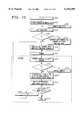
- FIG. 13is a plot of BER vs. SNR for BPSK modulation for the system of FIG. 1;
- FIG. 14is a plot of PSNR vs. C/N o for the system of FIG. 1;
- FIG. 15is a flow diagram of operation of a subband image coder incorporating progressive transmission.
- This inventionsignificantly improves the quality of a digitally transmitted image over the varying channel conditions.
- Image qualityis significantly improved for both additive white Gaussian noise and fading channels.
- Image qualityis significantly improved during the most adverse channel degradations.
- This inventionreduces the complexity encountered using fixed aggregate rate schemes.
- fixed aggregate rate systemsthe source and channel coding rates are allowed to vary, but the whole sum of the image coding bit rate plus the channel coding bit rate is constant. Thus, if the aggregate rate is fixed, the sum of the rates of the source and channel coding is equal to the aggregate rate.
- Optimal image qualityis obtained by allowing the transmitter power level to vary, and utilizing multiple source encoding rates, channel coding rates/strategies, modem diversity, and image delivery rate.
- the method of the inventionalso provides improved processing gains for spread spectrum communication systems where low probability of intercept (LPI) and low probability of detection (LPD) are important.
- LPIlow probability of intercept
- LPDlow probability of detection
- the method and apparatus of the inventionimproves the quality of digitally transmitted compressed digital imagery over degraded wireless communication links.
- the method and apparatuswill also improve the quality of the same imagery transmitted over wireline communication links.
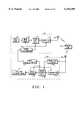
- the block diagram of an image communication system employing the adaptive technique of the inventionis shown in FIG. 1.
- critical operating pointsOP crit
- These critical operating pointsdetermine the optimum image coding rate, channel coding rate, channel coding strategy, and the process of modulation/demodulation.
- the optimum operating parameterscan only provide a sufficient image quality for a mild change in channel conditions. If channel conditions change sufficiently, the previous operating parameters are no longer optimal for providing the maximum image quality possible given a new set of channel conditions.
- new critical operating pointsare determined so that the system can now operate optimally for the current channel conditions.
- This systemis adaptive to varying communication channel conditions such that the optimal image quality is obtained.
- This techniquejointly minimizes the distortion due to channel bit errors, i.e., increased bit errors occur in the channel due to a reduction in the available channel capacity, and distortion due to lower source coding bit rates.
- Channel statusis defined as the state of the channel that requires critical operating points, denoted as OP crit (i) for optimal image quality for the ith channel condition.
- the channel statusis determined by measuring, for example, the quality, signal to noise ratio (S/N), and symbol error rate (SER) or bit error rate (BER) of the received signal. The value of this parameter determines the condition (or status) of the digital image communication channel.
- the critical operating pointsare determined according to the communication system's BER (or SER) vs. S/N and bit sensitivity performance. Thus, as the channel status changes, so must the critical operating points.
- the initial state of the systemcan be set at a reasonable expected channel condition, based on the average signal quality, S/N and BER or SER measured during operational testing of the system in the field.
- This initial stateis set by the transmitter 101, decoded by a system state estimator 125 at receiver 103.
- the system state estimator 125then outputs the critical operating points for the system at the current channel condition state determined by the transmitter and is denoted as OP crit (i). All encoding and decoding processes are based on OP crit (i).
- Receiver 103constantly monitors channel status via performance parameters from demodulator 117, channel decoder 119, and image decoder 121.
- SNRreceived signal-to-noise ratio
- Received SNRis a parameter that changes due to a multitude of causes.
- the channel modelis used as a vehicle to simulate these causes of variation in the SNR.
- BERis then a critical parameter used to estimate the performance of the communication system. In order to minimize the effects of variations in SNR on system performance, the BER must be estimated accurately. This accurate BER estimate will allow the system to intelligently adapt to changing channel conditions.
- the BERcan be estimated from the statistics of the SNR of the demodulator constellation, from the error corrections of the channel coder (and from the error corrections of the inner decoder, if any).
- the amount of fading and link marginscan be estimated from the time variance of the measured SNR and BER statistics.
- the error rate (BER)can be estimated by averaging the number of corrected errors over a sufficiently long number of received bits (or symbols) in a sequence.
- the number of bits used in this averagecannot be too large, however, because that would cause an excessive transition time between modes (thus the channel may already have changed again). Too few bits used in an average may cause the adaptive rate image coder to unnecessarily switch compression modes. If the system is in a condition where channel coding is not used, then there will be no error corrections, and the BER must be estimated by a different method. The following will show how BER can be estimated from the signal constellations of BPSK, 4-PSK, and 16-QAM modulation schemes.
- the demodulator sliceressentially selects, as a decision, the data symbol corresponding to the point in the signal constellation that is closest to a received sample. This is called optimal detection in a maximum likelihood (ML) sense as discussed in the text "Digital Communication” by Lee and Messerschmitt, Kluwer Academic Publishers, Boston, 1988.
- the slicerselects the symbol in the alphabet that minimizes the Euclidean distance (d) to the received signal sample Q k .
- Table 1shows information on how BER would be computed based on the information presented above.
- Q()is the well known complementary error function and P e is the probability of symbol error.
- the probability that a symbol error occurs for a ML detectoris equivalent to the probability that the received sample is closer to a symbol that is not the symbol that was sent.
- an alphabet having only two complex-valued symbolsnamely a m and a n .
- the probability of a symbol erroris simply the probability that Q k is closer to a n than a m and can be written as P[slicer prefers a n when a m was transmitted].
- the slicerwill prefer a n over a m (assuming a m was transmitted) if and only if:
- Equation (5)can be used to compute the probability of a symbol error for any of the constellations listed in Table 1. As a comparison, reference the relative SNR in each Pe equation of Table 1. Note that 4-PSK requires 3 dB more SNR than the binary antipodal signal to achieve the same probability of error. In comparing 16-QAM to 4-PSK, we will find that the 16-QAM signal requires 7 dB [10log(5)] more SNR than the 4-PSK signal, when using the "rough P e " equations of Table 1. Note, however, that the 16-QAM signal carries twice as much data in the same bandwidth as the 4-PSK signal, so Pe vs. SNR should not be considered alone. Note that for digital systems E b /N o (bit energy per noise spectral density) is often used as the signal to noise ratio parameter. E b /N o is related to SNR by the following equation:
- E cb /N ocoded bit energy per noise spectral density
- R cbis the channel bit rate. If no channel coding is employed R s is related to R b by:
- nis the total number of message (or coded) bits and k is the number of data bits.
- the quantity (k/n)defines the rate of the error (channel) coding.
- R bis expanded (making it R cb ) by the factor of one over the code rate, (n/k).
- the measurement duration, T snrwill be correlated with the duration of the average fade in the channel, T fade , in the following manner:
- wis some constant determined by simulation or field testing to minimize the reconstructed image distortion.
- T snra measurement duration correlated with the longest fade that is correctable via channel coding. Any fade longer than this time may cause excessive bit errors and thus would require a change based on the switching algorithm.
- the channel coding utilizedwill correct burst errors, similar to those caused by fading, and random errors due to additive white Gaussian noise.
- any delays between the transmitter 101 and the receiver 103must be taken into account to ensure the loop is stable under all circumstances.
- One type of delay that will carry a large range of valuesis the propagation delays between the transmitter and receiver. This delay is denoted as:
- T ptx and T prcvare the transmitter to receiver and receiver to transmitter propagation delays, respectively. Additionally, before any control signal can be sent back to the transmitter 101, the delay due to demodulation, SNR measurement and processing is also important to take into account. These other delays can be denoted as:
- T snris as defined above and T dem and T proc are the delays used for the demodulation and all other signal processing (including channel state estimation) operations.
- a method to ensure loop stabilitywould be to provide a guard band between bursts of the transmitter so that the transmitter receives the next control signal before the next burst.
- This guard time, T guardmust then be greater than the sum of T plot and T proc .
- This guard timemay be set as a function of multiple bursts instead of every burst to improve transmission efficiency. It is clear that the processing time may vary depending on the symbol rate, other modem diversity parameters, and channel coding changes, but the largest variation is likely to be due to a large propagation distance between the transmitter and receiver.
- T guardcan be set to be a function of the maximum expected distance or could be configured to be variable based on calibrated measurements between transmitter and receiver.
- FIG. 1a communication system using an adaptive method for transmission of very high quality digitally compressed imagery is shown in block diagram form.
- the system of FIG. 1includes a transmitter 101 and a receiver 103.
- a wireless communication link 105couples the transmitter 101 to the receiver 103.
- Adaptive transmitter 101includes image source 107, which may be a camera that takes a still image.
- Image coder 109coupled to image source 107, codes a digital bit stream coming from image source 107 to reduce the amount of bandwidth that is required to transmit the image from the transmitter 101 to receiver 103.
- a channel coder 111which may be of any conventional type, such as a forward error correcting coder which protects any of the bits in the image coder 109 which are deemed necessary to have good reconstruction at receiver 103.
- modulator 113takes the channel coded information from channel coder 111, up samples, performs D/A conversion, and filters (not necessarily in that order) the information and delivers it to the antenna 102 which puts the analog signal in proper form for transmission via link 105.
- Antenna 102provides coupling between transmitter 101 and the communications link 105.
- a channel status monitor 115initializes the transmitter 101 at power up by providing initial state parameters to transmitter 101.
- Channel status monitor 115is linked to image coder 109,channel coder 111 and modulator 113, to provide parameters that each of the blocks 109, 111 and 113 need to function at that particular instant.
- Communications link 105 in this embodimentis a wireless, RF (radio frequency) path.
- link 105is not limited to radio frequency links.
- Link 105could, for example, be an optical link utilizing lasers.
- Image source 107can be a digital image source such as a data file containing digital image data.
- Image coder 109receives the digital data representative of an image and codes the data in a way that allows data compression. In another embodiment of the invention, image coder 109 determines if the image data may be transmitted progressively.
- Channel coder 111takes the compressed data from image coder 109 and applies redundancy to the source information so that if errors occur in the communications link 105, the channel decoder 119 in receiver 103 can correct them. The amount of channel coding that is used is changed, depending on what the channel is doing.
- Modulator 113is chosen according to the type of modulation desired. The modulation may be changed and critical operating points of the system selected based on the modulation selected for use.
- Channel status monitor 115is coupled to modulator 113 and can change the modulation rate and the transmit power.
- Image coder 109, channel coder 111, and modulator 113are implemented in software in the illustrative embodiment of the invention, but in other embodiments may be implemented in hardware.
- Modulator 113 of transmitter 101includes a filter, a D/A converter, and an up converter coupled to antenna 102.
- Channel status monitor 115receives signals from receiver 103 over the reverse channel in a full duplex link.
- Channel status monitor 115receives information from receiver 103 on how the communication link 105 between the transmitter 101 and receiver 103 is changing and adjusts the transmit parameters accordingly to optimize the quality of the source information.
- the path between receiver 103 and channel status monitor 115may be a wired or wireless channel.
- Receiver 103receives information via a communications link 105 established from antenna 102 of transmitter 101 to antenna 104 associated with receiver 103.
- the received signalis applied to a system state estimator 125 and a demodulator 117, which looks at that information.
- the system state estimator 125estimates what the current operating parameters are that the transmitter has set for this particular time.
- System state estimator 125inputs those parameters to a channel decoder 119 and image decoder 121.
- Demodulator 117recovers the information according to the correct operating parameters and transfers the recovered information to channel decoder 119 and an image decoder 121.
- a data sink 123reconstructs the image from the received information.
- Data sink 123can be a data file or could also include a display monitor or other hardware or software which utilizes image data.
- Channel decoder 119 and image decoder 121together perform the reverse process of the equivalent blocks 109, 111 in transmitter 101.
- demodulator 117In order for demodulator 117, channel decoder 119, and image decoder 121 to operate correctly they must be programmed with appropriate parameters.
- the system state estimator 125serves to decode that information.
- Channel status estimator 127takes performance information from image decoder 121, channel decoder 119 and demodulator 117.
- Channel status estimator 127looks at, for example, reconstructed peak signal to noise ratio (PSNR) of the image decoder 121, bit error rate out of the channel decoder 119, symbol error rate (SEP) and the signal quality or signal to noise ratio (SNR) out of the demodulator 117.
- PSNRpeak signal to noise ratio
- SEPsymbol error rate
- SNRsignal quality or signal to noise ratio
- channel status estimator 127stores the information in memory and determines from the PSNR, channel decoder BER, demodulator BER, and/or estimated demodulated SNR to decide and calculate any necessary to change transmit parameters to better improve the image quality at the receiver.
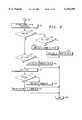
- the systeminitializes all of the parameters at step 200.
- the i th received input signal from the communications link 105is received.
- the current system state, S(i)is decoded.
- the i th signalmay be multiple data bits/bytes and will depend on how the image is coded and the RF carrier access scheme.
- System state estimator 125provides the system state decode called for in step 202.
- a determinationis made as to whether the decoded current system state S(i) is valid. If S(i) is not valid, the decoded system state vector is approximated at step 207.
- step 202When approximating the state vector, it is approximated to be the same as in the immediate prior state vector if it is determined to be closest in hamming distance to the actual decoded state vector S(i) in step 202. Otherwise, the next closest valid state vector, in terms of hamming distance relative to S(i), from step 202 is used. Demodulation and channel decoding based on that approximation occurs at step 208. In step 210, the signal quality, SNR, BER, and SER are estimated.
- the operating parameters for this received frameare checked to determine whether they are the same as the previous operating parameters or whether they are changed at step 204. If the operating parameters are the same, then the prior operating parameters are utilized as indicated at step 209. If the operating parameters are not the same, the operating parameters are updated based on what S(i) is at step 206.
- demodulation and channel decodingoccurs at step 209 and then at step 210 the signal quality, SNR, and BER, or SER are estimated.
- step 210the signal quality is checked at step 220. If the signal quality is "ok” based upon the approximated decoded system state vector, the image decoder 121 reconstructs the image as indicated at step 211 and thence to step 213 when the reconstruction is complete. From step 220, the process further advances to flow connector 218 which connects with connector 314 of the flow diagram of FIG. 3. If the signal quality is not "ok” as determined at step 220, then the process branches back to step 207 and approximates to the next most probable decoded system state vector.
- the processalso advances to connector 314 so that the current channel condition can be estimated.
- FIG. 3illustrates estimation of the channel status vector CS(i).
- CS(i)is estimated based on the switching algorithm of FIGS. 5 through 9.
- the system state S(i)is checked for validity at step 316. If the current system state is valid, the system determines whether the channel status vector CS(i) is in proportion to the current system state S(i) at step 318. If it is, then S(i) is sent to the transmitter 101 and a counter CSI is set to zero at step 320.
- CS(i)is sent to transmitter 101 at step 321 because that means the channel status has changed.
- counter CSIis set to zero and sent to transmitter 101.
- step 317if the estimated S(i) (i.e., S'(i)) is approximately related to CS(i) then CS(i) is sent to transmitter 101 at step 319.
- counter CSIis set to 0. If S(i) is not approximately related to CS(i), then counter CSI is incremented at step 322.
- step 323if the count of counter CSI is greater than some critical value N crit a re-synchronization notice is sent to transmitter 101 at step 324. If counter CSI is not greater than the critical value, CS(i) is sent to transmitter 101 at step 325.
- FIG. 4a flow diagram of an algorithm in the channel status monitor 115 of transmitter 101 is described.
- the transmitter 101is initially powered up and initialization occurs setting state vector S to an initial value.
- the i th channel status signalis inputted.
- the channel status indicatoris checked at step 403 to determine if it is valid. If CS(i) is not valid, an estimated channel status vector CS'(i) is generated at step 409. If CS(i) is valid as determined at step 403, the next system state vector S(i+1) is computed based on CS(i) at step 404.
- the new state vector S(i+1)is compared to the prior state vector S(i) to determine if they are equal. If they are equal, the same operating conditions are maintained as indicated at step 406. If the new state vector is not equal to the prior state vector, critical operating data is updated at step 407 based on the system state vector S(i+1) computed at step 404.
- the image code, channel code and modulationis determined.
- step 403if CS(i) is not valid, a procedure similar to that used in the receiver 103 to estimate the channel status vector is used at step 409.
- the system state vector S(i+1)is set to be proportional to the channel status vector.
- the systemadapts to the degradation by following predetermined adaptive processes.
- the adaptive processmay use information that the receiver portion of the transceiver has as signal quality parameters to maximize signal quality.
- a further part of the switching algorithm for the receiveris shown in flow diagram form in FIG. 5.
- the signal qualitysuch as PSNR
- SNRSNR
- SERSER
- BERBER
- the channel status CS(i)is set such that the old channel status CS -- O is set equal to the new channel state estimate CS -- N.
- CS -- Nwill be at a default value at power up and initialization.
- CS -- Nis defined for nominal channel condition or at a predetermined starting value determined by field measurements.
- channel statusis calculated based on a function of the quality parameters identified at step 501.
- a determinationis made as to whether the channel state is better or worse than the old.
- the processbranches to step 505 and the time parameter identified as T crit , which is the time parameter that is used to figure out how long the channel has been bad, is decremented. If the channel state is better, the new channel status is incremented at step 508. If the channel state is unchanged, T crit is set to zero at step 507. From steps 505, 507 and 508 the process advances to step 509 at which the channel status is calculated.
- the channel statusmay in the illustrative embodiment have one of four values. The higher the channel status number, the better quality of signal that it emits or the better state that the channel is in.
- the channel statusis looked at. Based upon the channel status number, one of four connections 511, 512, 513 or 514 is selected. Connection 511 corresponds to very bad channel status, 512 corresponds to bad, 513 corresponds to a nominal channel; and connection 514 means that it's very good.
- each channel state in FIGS. 6-10are representative of an adaptive system capable of only incremental changes, such as 6 dB, 3 dB, 1.5 dB, etc. It is important to state that the system of the present invention is capable of many discrete changes in power levels, baud rate, channel code rate, compression rates, delivery rate, progressive transmission strategies, and others.
- the flowchartsillustrate a preferred embodiment, using a limited number of discrete changes, which produces significant quality enhancements with little additional complexity compared to a fixed rate system.
- step 602it is determined if the option of varying transmit power is available as an option. If varying the power is an option, then at step 604 a determination is made as to whether it is desirable to reduce the baud rate. If it is desirable to reduce the baud rate, then the process will branch to connector 607. If it is determined that it is not desirable to reduce the baud rate, then the power will be increased by 6 db at step 606. If it is not possible to raise the power at step 602, then a determination is made at step 643 as to whether the baud rate should be reduced. If the baud rate is not to be reduced then the algorithm is complete.
- the baud rateis reduced by 6 db at step 603.
- the transmission ratemay also be varied at step 603.
- the next stepis to determine whether the delivery rate should be reduced as shown at step 605.
- the delivery rateindicates how many images are delivered per unit time. If it is determined not to reduce the delivery rate, then at step 608 a determination is made as to whether to use progressive image transmission. If in step 608 it is determined to use progressive transmission, a progressive transmission process is employed as indicated at step 609. If progressive transmission is not to be used, the compression ratio is increased by 6 dB as indicated in step 610. If at step 605 it is determined to reduce the delivery rate, the system reduces the delivery rate at step 611.
- step 614the power is increased by 3 dB and the baud rate decreased by 3 db.
- a determinationis then made at step 615 as to whether the delivery rate should be reduced. If it is decided to reduce the delivery rate, then at step 619 the delivery rate is reduced while maintaining the same compression ratio and channel coding, after which this portion of the operation is complete as indicated at step 620. If at step 615, it is decided to not reduce the delivery rate, at step 616 a determination is made as to whether to utilize progressive transmission.
- step 618progressive transmission of the image data occurs, after which the operation is complete at step 620. If, on the other hand, it is determined to not utilize progressive transmission, the compression ratio is increased as indicated at step 617 while maintaining the same channel coding.
- step 811a decision is made as to whether or not to change the operational strategy for the system. If it is decided not to change the strategy, a selective negative acknowledgment for any bad data blocks is sent at step 803, but only if the delivery rate is within the guaranteed delivery rate. This operation is then complete as indicated at step 811.
- step 804a decision is made at step 804 as to whether or not the channel state is close to being at state 2 as indicated at step 510 of FIG. 5. If it is determined that the channel state is not near state 2, the channel is probably better than nominal and at step 806 a decision is made as to whether the power can be reduced. If the power can be reduced, than at step 809, the transmit power is reduced by an amount determined by the channel. state estimator 127 shown in FIG. 1 in accordance with the method shown in the flow diagram of FIG. 9. If the power is not to be reduced, the compression ratio is changed and/or the channel coding is changed as indicted at step 810.
- step 902a decision is made as to whether to vary the transmit power. If the power can be varied, the process branches to connector 903 and to the process shown in the flow diagram of FIG. 10, which is described below. If the power can not be varied, a decision is then made at step 904 as to whether the baud rate may be increased. If the baud rate can not be increased, then this portion of the process is done as indicated at step 918. If the baud rate can be increased, then a further decision is made as to whether the delivery rate can be increased at step 906.
- the delivery ratecan not be increased, then a decision is made as to whether the compression ratio can be decreased as indicated at step 907. If the compression ratio can not be decreased, the number of bits per second is increased by 3 dB as indicated at step 909 and the process is complete as indicated at step 918. If the compression ratio can be decreased, then it is decreased and a higher resolution image is transmitted as indicated at step 910 and the process is complete at step 918.
- step 905it is further determined at step 905 whether the compression ratio may be decreased. If it can not, the bit rate is increased by 3 dB while holding the compression ratio constant, thereby causing the image delivery rate to double, as indicated in step 908 and the process is complete as indicated at step 918. If at step 905 it is determined that the compression ratio can be decreased, a determination is made as to whether or not the channel coding rate can be changed at step 911. If it can, a further decision is made at step 912 as to whether or not the channel bits can be decreased by 3 dB. If not, at step 913 most channel coding bits are removed at step 913 only protecting the necessary most sensitive image bits. Then a higher resolution image is transmitted at step 917. The higher resolution image takes less time to be transmitted.
- step 912If at step 912 it is determined that the compression ratio bits can be changed by 3 db, the number of bits per second is increased and the compression ratio is decreased at step 915. There is thus less error protection, but there are fewer errors on a channel. By increasing the number of bits per second, and decreasing the compression ratio, there are more image bits (i.e., higher resolution image) and it takes less time to transmit the image.
- step 911If at step 911 it is determined that the channel coding rate can not be changed, the compression ratio is decreased by 1.5 dB and the channel coding bit rate is also decreased by 1.5 dB (which holds the channel coding rate n/k constant) at step 914.
- the bits per secondis increased by 3 dB so it takes half as long to transmit the image. The process is thus complete at step 918.
- step 902determines that the power can be varied.
- the processis connected to step 920 at FIG. 10.
- step 920a determination is made as to whether the baud rate can be increased. If not, the transmit power is decreased by 3 db at step 922 and the process is complete at step 934. If at step 920 it is determined that the baud rate can be increased, the transmit power is decreased by 1.5 dB and the baud rate is increased by 1.5 dB at step 921. Then, a decision is made as to whether the delivery rate can be increased at step 923. If the delivery rate can not be increased, then a determination is made as to whether the compression ratio can be decreased at step 925.
- the compression ratiocan be decreased, a higher resolution image is transmitted as indicated at step 927 and the process is done as indicated at step 934. If the compression ratio can not be decreased, the bit rate is increased by 1.5 dB and the amount of user data transmitted is increased as indicated at step 928.
- step 923If at step 923 it is determined that the delivery rate can be increased, a decision is made as to whether or not the compression ratio can be decreased as indicated at step 924. If the compression ratio can not be decreased, the number of bits per second is increased 1.5 dB and the compression ratio is maintained constant as indicated at step 926 and again the process is done as indicated by step 934. This allows the image to be transmitted in less time.
- step 929if channel coding can be changed. If not, the compression ratio is decreased by 0.75 dB and the channel coding bit rate will correspondingly decrease by 0.75 dB as indicated at step 931. Note that the channel coding strategy will still be the same (i.e., same ratio of channel coded bits to information bits). The bit rate is increased at step 933 by 1.5 dB and it takes somewhat less time to transmit that image. If the channel coding can be changed, then channel coding bits are removed at step 930 only protecting the necessary image bits and the image compression ratio is reduced. Thus, as indicated in step 932, a higher resolution image is transmitted in less time.
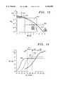
- the nominal operating condition for the systemwill be determined partially by the modulation performance curves and additionally by the bit error sensitivities of the image coder 109. If we assume that the image coder/decoder suffers little or no degradation if the bit error rate is less than approximately 10 -3 , then we can set the nominal operating condition for the system around this bit error rate. If the received SNR drops below this value corresponding to a 3(10 -2 ) BER, then we may wish to provide channel coding either in a higher sense or with a different strategy. This corresponds to region 3 of FIG. 13. If our received SNR is high, our strategy may be to decrease compression ratio or increase the image delivery rate, which may correspond to region 4 of FIG. 13.
- FIG. 13shows the advantage which is provided by channel coding, where this advantage occurs, and where channel coding is of no use in terms of BER.
- the graphis an indicator of what state the channel is in and what the corresponding switching strategy would be.
- the method of the inventionminimizes the overall distortion for the received image.
- the source encoding rate or the number of bits per image pixel (compression ratio)is the distortion after decoding due to channel bit errors.
- one method to reduce channel bit errorsis to more properly align the modulation symbol rate with the available channel capacity, which will reduce the bit error rate (BER). This, however, means that we must reduce the number of bits per image pixel, assuming constant image delivery rate. We can then perform the tradeoff between an increase in distortion of the image due to a lower encoding rate with a reduction in image distortion due to a decrease in modem symbol rate (decrease in the BER).
- FIG. 14An example of this method is illustrated in FIG. 14. From FIG. 14, we have used an image coder with a differentially coherent 4PSK modulation (D4PSK) with an adaptive symbol rate modem operating over a 20 dB-Hz range in average received power (C) to noise spectral density (N o ), (i.e., C/N o ), in an additive white Gaussian noise channel.
- D4PSKdifferentially coherent 4PSK modulation
- N onoise spectral density
- FIG. 14shows four curves 1102, 1104, 1106, and 1108, each corresponding to a different system configuration, as shown in Table 2.
- Embedded source coding approacheswhile typically less complex than multi-mode source coding, may not provide sufficient coding gains necessary under certain channel conditions.
- multi-mode source encodingmay be utilized, however, it is also directly applicable when embedded source encoding is required.
- the modulation waveformcould also be adjusted so that the relative received bit energy will allow the system to operate at a lower bit error rate.
- Modem diversity through symbol rate adjustmentprovides a lower bit error rate, providing a better match to the source encoding rate. This can be illustrated by studying the continuous channel capacity (Shannon-Hartley theorem) with additive white Gaussian noise. This is given by:
- Dis the channel capacity
- This resultis significant in a number of ways.
- providing this capability to extend to image qualityalso extends the link usability.
- This methodalso provides a means of guaranteeing image delivery rate, varying the transmitter power level, while providing the optimal level of image quality. If the system were operating at its maximum source information rate, as the channel capacity drops so does the ability to achieve a sufficiently low bit error probability and consequently causes the reconstructed image quality to degrade below that of a higher compression ratio (lower symbol rate at the modem). Additionally, the system could lose its ability to close the communications link (a downed link). This can easily be illustrated by imagining a link that is used in a mobile application where the link is subject to long duration deep fading.
- This method and apparatus of the inventioncombines variable rate source and channel coding for digitally compressed imagery with adaptive modem design. It also provides a means of either guaranteeing an image delivery rate while providing optimal image quality for that rate or varying this rate. Although limited references can be found on each topic in exclusion, there are no known authors or manufacturers of such an adaptive technique for achieving high image quality in a communication system.
- FIGS. 11 and 12are flow diagrams illustrating the operational flow within step 210 of FIG. 2. In FIGS. 11 and 12 and the following description, the following symbols are used:
- y iis the received signal into the receiver
- Nis the number of past received signals to store in the memory
- DAspecifies whether the SNR estimate data is aided (Y for yes and N for no);
- ⁇ 'is the signal to noise ratio estimate
- E ⁇ ⁇denotes the expected value operator
- M 2is defined as E ⁇ y i 2 ⁇ ;
- M 4is defined as E ⁇ y i 4 ⁇ ;
- BER d (i)is the bit error rate out of the demodulator for the i th received signal
- BER c (i)is the bit error rate out of channel coding
- n eis the number of bit errors uncorrected by the channel coder
- n tis the total number of bits processed
- PSNR ais the peak signal to noise ratio of the reconstructed image
- PSNR eis the expected PSNR
- k critis the maximum number of iterations the loop can go through before sending resynchronization notice to the transmitter.
- the parametersare initialized. Signals are stored in memory at step 704.
- the memoryis read.
- the read signals from step 706 and the initialized parameters from step 702are used at step 708 to determine whether a data aided (DA) signal to noise estimation procedure is used. If data aided estimation is not to be used, the equation shown in step 710 is used to calculate ⁇ '. If data aided estimation is to be used, the equation shown in step 712 is used to calculate ⁇ '. Regardless of which way ⁇ ' is calculated, the signal to noise ratio is determined from the ⁇ ' at step 714. In step 716, the bit error rate BER out of the demodulator is estimated. Various methods may be used to determine BER.
- BERchannel coding
- BER c (i)is computed at step 722. If no channel coding is used, BER c (i) is indicated as "not available” at step 724.
- a determinationis made as to whether or not there is known transmitted image data at step 728. If there is known transmitted image data, the PSNR a is calculated at step 726.
- the differential peak signal to noise ratiois calculated. If there is no known image data as determined from step 728, the peak signal to noise ratio is identified as "not available”.
- a determinationis made as to whether it is the first iteration or not. If it is the first iteration, signal quality parameters are set at step 742. And the iteration identifier k is incremented at step 744, or if the iteration determination at step 740 is that it is not the first iteration, the iteration identifier is likewise incremented.
- the signal quality parameters SQare calculated.
- a quality metricis determined according to equations.
- the signal quality SIGQUAL(i,k)is determined for the i th signal and iteration k.
- it is determined whether the signal for the present iteration is approximately equal to the signal quality for the initial iteration SIGQUAL(i,0), i.e., when k0. If not, then at step 754 it is determined whether k is greater than k crit . If it is, an indication is provided at step 756 that the signal is not "ok". If, however, k is greater than k crit , the signal quality is set equal to approximately a minimum as indicated at step 758 from which a re-synchronization signal is sent to the transmitter at step 760.
- FIG. 13illustrates a plot of BER vs. SNR for BPSK modulation.
- the characteristic curve 1010 for no channel codingtraverses four decision regions.
- Region 1002represents a very bad channel (1).
- Region 1004is where the channel is bad (2).
- Region 1006is where the channel is nominal (3).
- Region 1008defines where the channel is good (4).
- the other values of the BER vs. SNRcan be calculated and stored as modulation performance tables in memory.
- FIG. 14illustrates plots of PSNR vs. C/N o .
- Curve 1102illustrates the characteristic performance curve for the image coder at 1 bit/pixel, no channel coding, full rate D4PSK modulation.
- Curve 1104is for the image coder at 1/2 bits/pixel, 1/2 rate of convolutional channel coding, and full rate D4PSK modulation.
- Curve 1106is for the image coder being set to 1/4 bits per pixel, 1/2 rate channel coding, and 1/2 rate D4PSK.
- Threshold 1110establishes a region in which the channel is considered good. This corresponds to channel state 4.
- Region 1112defines a region in which the channel is considered nominal corresponding to channel state 3.
- Region 1114defines a region in which the channel is bad corresponding to channel state 2.
- Region 1116defines a region in which the channel is very bad corresponding to channel state 1.
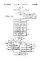
- FIG. 15illustrates transmission of still images with the subband image coder incorporating progressive transmission.
- the progressive transmission iteration iis set equal to 1.
- N-band subband decompositionis performed by successive low pass and high pass filtering operations followed by subsampling by a factor of 2.
- an optimum allocation of bits for the various subbandsis calculated using a compression ratio input at step 1208.
- a determinationis made as to whether or not to operate the encoder in the progressive transmission mode.
- step 1212takes each 2-D subband and groups the samples into a 1-D sequence and quantizes each sequence using a quantizer at a rate specified by a rate allocation block. If it is decided at step 1210 to operate the encoder in the progressive transmission mode, then step 1214 finds the most important subbands and quantizes them to the rate specified by the rate allocation module. The outputs of steps 1212 and 1214 are applied to an available channel at step 1216 (for example, passing through channel coder (FEC) 111, modulator 113, and antenna 102 before being transmitted on link 105). At step 1217, the quantization procedure is revised to convert the quantizer indices to reconstructed codeword values.
- FECchannel coder
- step 1220a determination is made as to whether or not the decoder is to be placed into the progressive transmission mode. If not, at step 1224 image pixels are reconstructed through subband reconstruction by successive application of interpolation and filtering of the subbands. At step 1236, the operation is complete.
- step 1220If at step 1220 it is determined to place the decoder into the progressive transmission mode, reconstruction of the image occurs through appropriately upsampling and filtering of received subbands to obtain the reconstructed image iteration. At step 1230, the reconstructed image is added to the reconstructed image from the prior iteration. At step 1232, it is determined if the subbands sent for pictures of an image are of sufficient quality, e.g., adequate PSNR. If the image quality is determined to be sufficient, the process is done as indicated by step 1236. If on the other hand, the image quality is not sufficient the progressive transmission counter is incremented by one at step 1234 and the process is repeated from step 1214. The decision to continue the progressive transmission process is made at the receiver 103 of FIG. 1 and sent to the transmitter 101 via the feedback channel.
- sufficient qualitye.g., adequate PSNR
Landscapes
- Engineering & Computer Science (AREA)
- Signal Processing (AREA)
- Multimedia (AREA)
- Quality & Reliability (AREA)
- Computer Networks & Wireless Communication (AREA)
- Detection And Prevention Of Errors In Transmission (AREA)
Abstract
Description
TABLE 1 ______________________________________ Constellation BPSK 4-PSK 16-QAM ______________________________________ alphabet {±a} {±b, ±jb} {(±c or ±3c) + j(±c or ±3c)} min. dist. d 2a b√2 2c power E[|A.sub.k |.sup.2 ] a.sup.2 b.sup.2 10c.sup.2 exact Pe Q(√2SNR) 2Q(√SNR) - 3Q(√SNR/5) - Q.sup.2 (√SNR) 2.25Q.sup.2 (√SNR/5) approximate Pe Q(√2SNR) 2Q(√SNR) 3Q(√SNR/5) rough Pe Q(√2SNR) Q(√SNR) Q(√SNR/5) ______________________________________|Q.sub.k -a.sub.n |.sup.2 <|Q.sub.k -a.sub.m |.sup.2 (1)
|a.sub.m -a.sub.n +Z.sub.k |.sup.2 <|Z.sub.k |.sup.2 (2)
Re{a.sub.m -a.sub.n }Re{Z.sub.k }+Im{a.sub.m -a.sub.n }Im{Z.sub.k }<-d.sup.2 /.sub.2 (3)([Re{a.sub.m -a.sub.n }].sup.2 +[Im{a.sub.m -a.sub.n }].sup.2)σ.sup.2 =d.sup.2 σ.sup.2 (4)Q((d.sup.2 /2)/sqrt(d.sup.2 σ.sup.2)))=Q(d/(2σ))(5)
(E.sub.b /N.sub.o)R.sub.b =S/N.sub.o (6)
(E.sub.s /N.sub.o)R.sub.s =S/N.sub.o [or E.sub.s /N.sub.o =(S/N.sub.o)/R.sub.s ] (7)
(E.sub.cb /N.sub.o)R.sub.cb =S/N.sub.o [or E.sub.cb /N.sub.o =(S/N.sub.o)R.sub.cb ] (8)
R.sub.s =R.sub.b /(log.sub.2 (M)) (9)
R.sub.cb =(n/k)*R.sub.b (10)
R.sub.s =R.sub.cb /(log2(M))=(n/k)*R.sub.b /(log2(M)) (11)
T.sub.snr =w*T.sub.fade, (12)
T.sub.plot =T.sub.ptx +T.sub.prcv, (13)
T.sub.proc =T.sub.snr +T.sub.dem +T.sub.proc (14)
TABLE 2______________________________________ Curve 1102Curve 1104Curve 1106Curve 1108 ______________________________________Image 1 bpp .5 bpp .25 bpp .125 bpp Coding Channel none half-rate half-rate half-rate Coding convolutional convolutional convolutional Baud Rate 131 131 ksym/s 65.5 ksym/s 32.75 ksym/s ksym/s ______________________________________
D=Wlog.sub.2 (1+C/N) (15)
Claims (11)
Priority Applications (1)
| Application Number | Priority Date | Filing Date | Title |
|---|---|---|---|
| US09/050,504US6154489A (en) | 1998-03-30 | 1998-03-30 | Adaptive-rate coded digital image transmission |
Applications Claiming Priority (1)
| Application Number | Priority Date | Filing Date | Title |
|---|---|---|---|
| US09/050,504US6154489A (en) | 1998-03-30 | 1998-03-30 | Adaptive-rate coded digital image transmission |
Publications (1)
| Publication Number | Publication Date |
|---|---|
| US6154489Atrue US6154489A (en) | 2000-11-28 |
Family
ID=21965610
Family Applications (1)
| Application Number | Title | Priority Date | Filing Date |
|---|---|---|---|
| US09/050,504Expired - LifetimeUS6154489A (en) | 1998-03-30 | 1998-03-30 | Adaptive-rate coded digital image transmission |
Country Status (1)
| Country | Link |
|---|---|
| US (1) | US6154489A (en) |
Cited By (91)
| Publication number | Priority date | Publication date | Assignee | Title |
|---|---|---|---|---|
| US20010011213A1 (en)* | 1998-09-25 | 2001-08-02 | Amir Hindie | Modem using a digital signal processor and a signal based command set |
| WO2002013432A1 (en)* | 2000-08-03 | 2002-02-14 | Lockheed Martin Corporation | Phase shift keyed signaling with forward error correction and raman amplification in optical wdm links |
| US20020053053A1 (en)* | 2000-10-31 | 2002-05-02 | Takeshi Nagai | Data transmission apparatus and method |
| US20020080735A1 (en)* | 2000-12-22 | 2002-06-27 | Heath Robert W. | Method and system for evaluating a wireless link |
| US6425105B1 (en)* | 1998-08-26 | 2002-07-23 | Nokia Networks Oy | Bidirectional ARQ apparatus and method |
| US20020097686A1 (en)* | 2000-11-20 | 2002-07-25 | Qiu Robert C. | Long-range prediction of fading signals for WCDMA high speed downlink packet access (HSDPA) |
| US6426971B1 (en)* | 1999-09-13 | 2002-07-30 | Qualcomm Incorporated | System and method for accurately predicting signal to interference and noise ratio to improve communications system performance |
| US20020108001A1 (en)* | 1998-09-25 | 2002-08-08 | David Pearce | Multi-modem implementation with host based and digital signal processor based modems |
| US6434191B1 (en)* | 1999-09-30 | 2002-08-13 | Telcordia Technologies, Inc. | Adaptive layered coding for voice over wireless IP applications |
| WO2002080561A1 (en)* | 2001-03-30 | 2002-10-10 | Telecom Italia S.P.A. | Method for providing television coverage, associated television camera station, receiving station and system |
| US20020168003A1 (en)* | 2000-11-13 | 2002-11-14 | Richards James L. | System and method of communicating high rate pulse signals in a multipath environment |
| WO2002056567A3 (en)* | 2001-01-12 | 2002-12-05 | Comsys Communication & Signal Processing Ltd. | Reduced soft output information packet selection |
| US20020191703A1 (en)* | 2001-03-23 | 2002-12-19 | Fuyun Ling | Method and apparatus for utilizing channel state information in a wireless communication system |
| US6502138B2 (en)* | 1998-09-25 | 2002-12-31 | Intel Corporation | Modem with code execution adapted to symbol rate |
| US20030005385A1 (en)* | 2001-06-27 | 2003-01-02 | Stieger Ronald D. | Optical communication system with variable error correction coding |
| US20030039226A1 (en)* | 2001-08-24 | 2003-02-27 | Kwak Joseph A. | Physical layer automatic repeat request (ARQ) |
| WO2003019812A1 (en)* | 2001-08-24 | 2003-03-06 | Interdigital Technology Corporation | Method for physical layer automatic repeat request for a subscriber unit |
| US20030052994A1 (en)* | 2001-09-17 | 2003-03-20 | Eric Auffret | Wireless video camera |
| US20030072376A1 (en)* | 2001-10-12 | 2003-04-17 | Koninklijke Philips Electronics N.V. | Transmission of video using variable rate modulation |
| US20030142727A1 (en)* | 2001-02-20 | 2003-07-31 | Pantelis Monogioudis | Decoderless bit-error-rate estimation for convolutionally encoded transmissions in wireless systems |
| US6611555B2 (en) | 1998-09-25 | 2003-08-26 | Intel Corporation | Integrated audio and modem device |
| US20030161285A1 (en)* | 2002-02-25 | 2003-08-28 | Tiedemann Edward G. | Method and apparatus for channel quality feedback in a wireless communication |
| US6625208B2 (en) | 1998-09-25 | 2003-09-23 | Intel Corporation | Modem using batch processing of signal samples |
| US6643322B1 (en)* | 2000-09-20 | 2003-11-04 | Aperto Networks, Inc. | Dynamic wireless link adaptation |
| US20040032835A1 (en)* | 1999-12-30 | 2004-02-19 | Aperto Networks, Inc | Integrated,self-optimizing,multi-parameter/multi-variable point-to-multipoint communication system [II] |
| US20040041945A1 (en)* | 2001-09-25 | 2004-03-04 | Pugel Michael Anthony | Apparatus and method for optimizing the level of rf signals |
| US6711205B1 (en) | 1998-09-25 | 2004-03-23 | Intel Corporation | Tone detector for use in a modem |
| US6711206B1 (en) | 1998-09-25 | 2004-03-23 | Intel Corporation | Modem using a digital signal processor and separate transmit and receive sequencers |
| WO2004056123A1 (en)* | 2002-12-17 | 2004-07-01 | British Telecommunications Public Limited Company | Quality based signal processing |
| WO2004056028A1 (en)* | 2002-12-18 | 2004-07-01 | Koninklijke Philips Electronics N.V. | Adaptive encoding of digital multimedia information |
| US20040205004A1 (en)* | 2000-02-22 | 2004-10-14 | Paramvir Bahl | Methods and systems for providing variable rates of service for accessing networks, methods and systems for accessing the internet |
| US20040207610A1 (en)* | 2003-03-18 | 2004-10-21 | Satoshi Kajita | Information terminal unit and communication method based thereon |
| US20040215956A1 (en)* | 2000-02-22 | 2004-10-28 | Microsoft Corporation | Methods and systems for accessing networks, methods and systems for accessing the internet |
| US6859463B1 (en)* | 1999-11-08 | 2005-02-22 | Itt Manufacturing Enterprises, Inc. | Methods and apparatus for organizing selection of operational parameters in a communication system |
| US20050053100A1 (en)* | 2003-09-08 | 2005-03-10 | Abousleman Glen P. | System and method for satelllite-based transmission of voice signals using an otherwise dedicated wireless channel |
| US20050149835A1 (en)* | 2003-12-17 | 2005-07-07 | Dacosta Behram Mario | Outage predictor for communication link |
| US20050164645A1 (en)* | 2004-01-26 | 2005-07-28 | Magnolia Broadband Inc. | Communicating signals according to a quality indicator using multiple antenna elements |
| US20050225681A1 (en)* | 2004-04-09 | 2005-10-13 | Young-Wook Sohn | Display apparatus |
| WO2005112449A1 (en)* | 2004-04-30 | 2005-11-24 | Worldgate Service, Inc. | Adaptive video telephone system |
| US20050265383A1 (en)* | 2004-06-01 | 2005-12-01 | Diego Melpignano | Method and system for communicating video data in a packet-switched network, related network and computer program product therefor |
| US20050265436A1 (en)* | 2004-06-01 | 2005-12-01 | Samsung Electronics Co., Ltd. | Method and apparatus for channel state feedback using arithmetic coding |
| US20060007994A1 (en)* | 2004-06-30 | 2006-01-12 | Kuei-Chiang Lai | Signal quality estimation for continuous phase modulation |
| US20060165011A1 (en)* | 2005-01-26 | 2006-07-27 | Sbc Knowledge Ventures, L.P. | System and method of managing digital data transmission |
| US7096034B2 (en)* | 2001-10-01 | 2006-08-22 | Microsoft Corporation | System and method for reducing power consumption for wireless communications by mobile devices |
| US20070015469A1 (en)* | 2005-06-27 | 2007-01-18 | Samsung Electronics Co., Ltd. | Dynamic channel allocation method in an OFDMA mobile communication system |
| US20070071030A1 (en)* | 2005-09-29 | 2007-03-29 | Yen-Chi Lee | Video packet shaping for video telephony |
| US20070081475A1 (en)* | 2005-10-11 | 2007-04-12 | Teranetics, Inc. | Multiple modulation rate 10Gbase-T transmission |
| US20070097257A1 (en)* | 2005-10-27 | 2007-05-03 | El-Maleh Khaled H | Video source rate control for video telephony |
| WO2007073508A1 (en)* | 2005-10-21 | 2007-06-28 | Qualcomm Incorporated | Method and system for adaptive encoding of real-time information in wireless networks |
| US20070286063A1 (en)* | 2006-03-17 | 2007-12-13 | Jocelyn Aulin | OFDM in Fast Fading Channel |
| FR2903253A1 (en)* | 2006-06-29 | 2008-01-04 | Thales Sa | METHOD FOR DETERMINING COMPRESSION AND PROTECTION PARAMETERS FOR TRANSMITTING MULTIMEDIA DATA ON A WIRELESS CHANNEL. |
| FR2903272A1 (en)* | 2006-06-29 | 2008-01-04 | Thales Sa | Operating parameter e.g. compression rate, determining method for transmitting e.g. multimedia data, involves selecting optimal sensitivity value that is defined by taking into account of desired source flow and compression rate |
| US20080013613A1 (en)* | 2006-07-13 | 2008-01-17 | Sunplus Technology Co., Ltd. | Method and system for controlling multimedia communication quality in a handheld device |
| KR100798714B1 (en) | 2001-08-24 | 2008-01-28 | 인터디지탈 테크날러지 코포레이션 | Method for requesting physical layer auto repeat at base station |
| US20080049661A1 (en)* | 1998-05-15 | 2008-02-28 | Jaleh Komaili | System and method for adaptive multi-rate (amr) vocoder rate adaptation |
| US7339881B1 (en) | 2003-04-18 | 2008-03-04 | General Dynamics C4 Systems, Inc. | Method and apparatus for encoding compressible data for transmission over variable quality communication channel |
| US20080063079A1 (en)* | 2006-09-12 | 2008-03-13 | Wang Zhongjun | Apparatus and method for receiving digital video signals |
| US20080074497A1 (en)* | 2006-09-21 | 2008-03-27 | Ktech Telecommunications, Inc. | Method and Apparatus for Determining and Displaying Signal Quality Information on a Television Display Screen |
| US20080256411A1 (en)* | 2005-11-28 | 2008-10-16 | Motorola, Inc. | Retransmission in a Cellular Communication System |
| US20090021572A1 (en)* | 2007-01-10 | 2009-01-22 | Qualcomm Incorporated | Content- and link-dependent coding adaptation for multimedia telephony |
| US20090034610A1 (en)* | 2005-10-21 | 2009-02-05 | Yen-Chi Lee | Video rate adaptation to reverse link conditions |
| US20090180379A1 (en)* | 2008-01-10 | 2009-07-16 | Qualcomm Incorporated | System and method to adapt to network congestion |
| US20090262850A1 (en)* | 2000-09-19 | 2009-10-22 | Severine Catreux | System and Method of Dynamically Optimizing a Transmission Mode of Wirelessly Transmitted Information |
| EP2055036A4 (en)* | 2006-08-21 | 2010-06-02 | Ericsson Telefon Ab L M | Method and arrangement for adapting transmission of encoded media |
| US20100226452A1 (en)* | 2009-03-03 | 2010-09-09 | Qualcomm Incorporated | Method and system for reducing feedback information in multicarrier-based communication systems based on frequency grouping |
| US20100318861A1 (en)* | 2000-09-19 | 2010-12-16 | Gesbert David J | Mode selection for data transmission in wireless communication channels based on statistical parameters |
| US20110007168A1 (en)* | 2009-07-09 | 2011-01-13 | Sony Corporation | Image receiving apparatus, image receiving method, and image transmitting apparatus |
| CN102036024A (en)* | 2009-10-07 | 2011-04-27 | 索尼公司 | Transmission apparatus and transmission method |
| US20110103443A1 (en)* | 2000-01-07 | 2011-05-05 | Aware, Inc. | Systems and methods for establishing a diagnostic transmission mode and communicating over the same |
| US7952990B1 (en)* | 2003-02-12 | 2011-05-31 | Marvell International Ltd. | Low complexity channel estimation for orthogonal frequency division modulation systems |
| US20120039207A1 (en)* | 2009-04-14 | 2012-02-16 | Telefonaktiebolaget Lm Ericsson (Publ) | Link Adaptation with Aging of CQI Feedback Based on Channel Variability |
| US8255569B1 (en)* | 2000-02-22 | 2012-08-28 | Microsoft Corporation | Methods and systems for compressing data packets |
| WO2012148238A3 (en)* | 2011-04-28 | 2013-01-10 | 삼성전자 주식회사 | Method and apparatus for adjusting a data transmission rate in a wireless communication system |
| RU2480918C1 (en)* | 2011-11-18 | 2013-04-27 | Федеральное государственное бюджетное образовательное учреждение высшего профессионального образования "Ульяновский государственный технический университет" | Adaptive coder of 3d dimension hypercode |
| US8514711B2 (en) | 2005-10-21 | 2013-08-20 | Qualcomm Incorporated | Reverse link lower layer assisted video error control |
| US20130290803A1 (en)* | 2012-04-27 | 2013-10-31 | International Business Machines Corporation | Variable acknowledge rate to reduce bus contention in presence of communication errors |
| US20130336380A1 (en)* | 2012-06-18 | 2013-12-19 | Broadcom Corporation | Power Optimization for Compression in Wireless Transmissions |
| US20130336661A1 (en)* | 2010-03-08 | 2013-12-19 | Astrium Sas | Method and system for free-field optical transmission by means of laser signals |
| US20140133848A1 (en)* | 2012-11-15 | 2014-05-15 | Mitsubishi Electric Research Laboratories, Inc. | Adaptively Coding and Modulating Signals Transmitted Via Nonlinear Channels |
| CN103999357A (en)* | 2011-10-24 | 2014-08-20 | 罗伯科技公司 | Method of displaying a digital signal |
| CN104303421A (en)* | 2012-03-12 | 2015-01-21 | 通维数码公司 | Method and apparatus for maximizing utilization of dynamically changing digital data channels |
| US20150119659A1 (en)* | 1999-03-01 | 2015-04-30 | West View Research, Llc | Application-specific ingestible apparatus for in vivo data collection and processing |
| US20150171961A1 (en)* | 2013-12-18 | 2015-06-18 | Northrop Grumman Systems Corporation | Optical transceiver with variable data rate and sensitivity control |
| WO2016116912A1 (en)* | 2015-01-25 | 2016-07-28 | Valens Semiconductor Ltd. | Fast adaptive mode-conversion digital canceller |
| US9621445B2 (en) | 2015-01-25 | 2017-04-11 | Valens Semiconductor Ltd. | Utilizing known data for status signaling |
| US9685991B2 (en) | 2015-01-25 | 2017-06-20 | Valens Semiconductor Ltd. | Reducing transmission rate to support fast convergence |
| US9861268B2 (en) | 1999-03-01 | 2018-01-09 | West View Research, Llc | Methods of processing data obtained from medical device |
| US10171182B2 (en) | 2015-01-25 | 2019-01-01 | Valens Semiconductor Ltd. | Sending known data to support fast convergence |
| US10256920B2 (en) | 2015-01-25 | 2019-04-09 | Valens Semiconductor Ltd. | Mode-conversion digital canceller for high bandwidth differential signaling |
| US10637570B1 (en)* | 2019-01-16 | 2020-04-28 | X Development Llc | Adaptive rate modem |
| US11991234B2 (en) | 2004-04-30 | 2024-05-21 | DISH Technologies L.L.C. | Apparatus, system, and method for multi-bitrate content streaming |
Citations (9)
| Publication number | Priority date | Publication date | Assignee | Title |
|---|---|---|---|---|
| US4756007A (en)* | 1984-03-08 | 1988-07-05 | Codex Corporation | Adaptive communication rate modem |
| US5243428A (en)* | 1991-01-29 | 1993-09-07 | North American Philips Corporation | Method and apparatus for concealing errors in a digital television |
| US5442625A (en)* | 1994-05-13 | 1995-08-15 | At&T Ipm Corp | Code division multiple access system providing variable data rate access to a user |
| US5541657A (en)* | 1991-08-13 | 1996-07-30 | Canon Kabushiki Kaisha | Image transmission with divided image signal transmission through selected channels |
| US5541955A (en)* | 1992-11-06 | 1996-07-30 | Pericle Communications Company | Adaptive data rate modem |
| US5671156A (en)* | 1995-03-31 | 1997-09-23 | Lucent Technologies Inc. | Transmission method and system for JPEG images |
| US5689439A (en)* | 1995-03-31 | 1997-11-18 | Lucent Technologies, Inc. | Switched antenna diversity transmission method and system |
| US5774483A (en)* | 1993-05-31 | 1998-06-30 | Samsung Electronics Co., Ltd. | Method and apparatus for recovering an image in a video telephone system |
| US5842113A (en)* | 1996-04-10 | 1998-11-24 | Lucent Technologies Inc. | Method and apparatus for controlling power in a forward link of a CDMA telecommunications system |
- 1998
- 1998-03-30USUS09/050,504patent/US6154489A/ennot_activeExpired - Lifetime
Patent Citations (9)
| Publication number | Priority date | Publication date | Assignee | Title |
|---|---|---|---|---|
| US4756007A (en)* | 1984-03-08 | 1988-07-05 | Codex Corporation | Adaptive communication rate modem |
| US5243428A (en)* | 1991-01-29 | 1993-09-07 | North American Philips Corporation | Method and apparatus for concealing errors in a digital television |
| US5541657A (en)* | 1991-08-13 | 1996-07-30 | Canon Kabushiki Kaisha | Image transmission with divided image signal transmission through selected channels |
| US5541955A (en)* | 1992-11-06 | 1996-07-30 | Pericle Communications Company | Adaptive data rate modem |
| US5774483A (en)* | 1993-05-31 | 1998-06-30 | Samsung Electronics Co., Ltd. | Method and apparatus for recovering an image in a video telephone system |
| US5442625A (en)* | 1994-05-13 | 1995-08-15 | At&T Ipm Corp | Code division multiple access system providing variable data rate access to a user |
| US5671156A (en)* | 1995-03-31 | 1997-09-23 | Lucent Technologies Inc. | Transmission method and system for JPEG images |
| US5689439A (en)* | 1995-03-31 | 1997-11-18 | Lucent Technologies, Inc. | Switched antenna diversity transmission method and system |
| US5842113A (en)* | 1996-04-10 | 1998-11-24 | Lucent Technologies Inc. | Method and apparatus for controlling power in a forward link of a CDMA telecommunications system |
Cited By (236)
| Publication number | Priority date | Publication date | Assignee | Title |
|---|---|---|---|---|
| US20080049661A1 (en)* | 1998-05-15 | 2008-02-28 | Jaleh Komaili | System and method for adaptive multi-rate (amr) vocoder rate adaptation |
| US8265220B2 (en) | 1998-05-15 | 2012-09-11 | Lg Electronics Inc. | Rate adaptation for use in adaptive multi-rate vocoder |
| US7613270B2 (en)* | 1998-05-15 | 2009-11-03 | Lg Electronics Inc. | System and method for adaptive multi-rate (AMR) vocoder rate adaptation |
| US20080059159A1 (en)* | 1998-05-15 | 2008-03-06 | Jaleh Komaili | System and method for adaptive multi-rate (amr) vocoder rate adaptation |
| US6425105B1 (en)* | 1998-08-26 | 2002-07-23 | Nokia Networks Oy | Bidirectional ARQ apparatus and method |
| US20010011213A1 (en)* | 1998-09-25 | 2001-08-02 | Amir Hindie | Modem using a digital signal processor and a signal based command set |
| US6611555B2 (en) | 1998-09-25 | 2003-08-26 | Intel Corporation | Integrated audio and modem device |
| US20020108001A1 (en)* | 1998-09-25 | 2002-08-08 | David Pearce | Multi-modem implementation with host based and digital signal processor based modems |
| US6711206B1 (en) | 1998-09-25 | 2004-03-23 | Intel Corporation | Modem using a digital signal processor and separate transmit and receive sequencers |
| US6711205B1 (en) | 1998-09-25 | 2004-03-23 | Intel Corporation | Tone detector for use in a modem |
| US6708235B2 (en) | 1998-09-25 | 2004-03-16 | Intel Corporation | Multi-modem implementation with host based and digital signal processor based modems |
| US6661848B1 (en) | 1998-09-25 | 2003-12-09 | Intel Corporation | Integrated audio and modem device |
| US6625208B2 (en) | 1998-09-25 | 2003-09-23 | Intel Corporation | Modem using batch processing of signal samples |
| US6502138B2 (en)* | 1998-09-25 | 2002-12-31 | Intel Corporation | Modem with code execution adapted to symbol rate |
| US10098568B2 (en) | 1999-03-01 | 2018-10-16 | West View Research, Llc | Computerized apparatus with ingestible probe |
| US10028646B2 (en) | 1999-03-01 | 2018-07-24 | West View Research, Llc | Computerized information collection and processing apparatus |
| US10154777B2 (en) | 1999-03-01 | 2018-12-18 | West View Research, Llc | Computerized information collection and processing apparatus and methods |
| US10973397B2 (en) | 1999-03-01 | 2021-04-13 | West View Research, Llc | Computerized information collection and processing apparatus |
| US9861296B2 (en) | 1999-03-01 | 2018-01-09 | West View Research, Llc | Ingestible probe with agent delivery |
| US20150119659A1 (en)* | 1999-03-01 | 2015-04-30 | West View Research, Llc | Application-specific ingestible apparatus for in vivo data collection and processing |
| US9913575B2 (en) | 1999-03-01 | 2018-03-13 | West View Research, Llc | Methods of processing data obtained from medical device |
| US9861268B2 (en) | 1999-03-01 | 2018-01-09 | West View Research, Llc | Methods of processing data obtained from medical device |
| US10028645B2 (en) | 1999-03-01 | 2018-07-24 | West View Research, Llc | Computerized information collection and processing apparatus |
| US6426971B1 (en)* | 1999-09-13 | 2002-07-30 | Qualcomm Incorporated | System and method for accurately predicting signal to interference and noise ratio to improve communications system performance |
| US6434191B1 (en)* | 1999-09-30 | 2002-08-13 | Telcordia Technologies, Inc. | Adaptive layered coding for voice over wireless IP applications |
| US6859463B1 (en)* | 1999-11-08 | 2005-02-22 | Itt Manufacturing Enterprises, Inc. | Methods and apparatus for organizing selection of operational parameters in a communication system |
| US7349426B2 (en) | 1999-12-30 | 2008-03-25 | Aperto Networks, Inc. | Integrated, self-optimizing, multi-parameter/multi-variable point-to-multipoint communication system [II] |
| US20040032835A1 (en)* | 1999-12-30 | 2004-02-19 | Aperto Networks, Inc | Integrated,self-optimizing,multi-parameter/multi-variable point-to-multipoint communication system [II] |
| US8929423B2 (en) | 2000-01-07 | 2015-01-06 | Tq Delta, Llc | Systems and methods for establishing a diagnostic transmission mode and communicating over the same |
| US10623559B2 (en) | 2000-01-07 | 2020-04-14 | Tq Delta, Llc | Systems and methods for establishing a diagnostic transmission mode and communicating over the same |
| US10264119B2 (en) | 2000-01-07 | 2019-04-16 | Tq Delta, Llc | Systems and methods for establishing a diagnostic transmission mode and communicating over the same |
| US9838531B2 (en) | 2000-01-07 | 2017-12-05 | Tq Delta, Llc | Systems and methods for establishing a diagnostic transmission mode and communicating over the same |
| US9264533B2 (en) | 2000-01-07 | 2016-02-16 | Tq Delta, Llc | Systems and methods for establishing a diagnostic transmission mode and communicating over the same |
| US9319512B2 (en) | 2000-01-07 | 2016-04-19 | Tq Delta, Llc | Systems and methods for establishing a diagnostic transmission mode and communicating over the same |
| US9479637B2 (en) | 2000-01-07 | 2016-10-25 | Tq Delta, Llc | Systems and methods for establishing a diagnostic transmission mode and communicating over the same |
| US9973624B2 (en) | 2000-01-07 | 2018-05-15 | Tq Delta, Llc | Systems and methods for establishing a diagnostic transmission mode and communicating over the same |
| US20130243049A1 (en)* | 2000-01-07 | 2013-09-19 | Tq Delta, Llc | Systems and methods for a transceiver to transmit or receive test information over a communication channel using multicarrier modulation |
| US8634449B2 (en) | 2000-01-07 | 2014-01-21 | Tq Delta, Llc | Systems and methods for establishing a diagnostic transmission mode and communicating over the same |
| US8743931B2 (en)* | 2000-01-07 | 2014-06-03 | Tq Delta, Llc | Systems and methods for a transceiver to transmit or receive test information over a communication channel using multicarrier modulation |
| US20110103443A1 (en)* | 2000-01-07 | 2011-05-05 | Aware, Inc. | Systems and methods for establishing a diagnostic transmission mode and communicating over the same |
| US7313237B2 (en) | 2000-02-22 | 2007-12-25 | Microsoft Corporation | Methods and systems for providing variable rates of service for accessing networks, methods and systems for accessing the internet |
| US7444510B2 (en) | 2000-02-22 | 2008-10-28 | Microsoft Corporation | Methods and systems for accessing networks, methods and systems for accessing the internet |
| US20040205004A1 (en)* | 2000-02-22 | 2004-10-14 | Paramvir Bahl | Methods and systems for providing variable rates of service for accessing networks, methods and systems for accessing the internet |
| US7548976B2 (en) | 2000-02-22 | 2009-06-16 | Microsoft Corporation | Methods and systems for providing variable rates of service for accessing networks, methods and systems for accessing the internet |
| US20040215956A1 (en)* | 2000-02-22 | 2004-10-28 | Microsoft Corporation | Methods and systems for accessing networks, methods and systems for accessing the internet |
| US20040221157A1 (en)* | 2000-02-22 | 2004-11-04 | Microsoft Corporation | Methods and systems for accessing networks methods and systems for accessing the internet |
| US20060168454A1 (en)* | 2000-02-22 | 2006-07-27 | Microsoft Corporation | Methods and systems for accessing networks, methods and systems for accessing the internet |
| US20050022001A1 (en)* | 2000-02-22 | 2005-01-27 | Microsoft Corporation | Methods and systems for providing variable rates of service for accessing networks, methods and systems for accessing the internet |
| US7500263B2 (en) | 2000-02-22 | 2009-03-03 | Microsoft Corporation | Methods and systems for accessing networks, methods and systems for accessing the Internet |
| US8255569B1 (en)* | 2000-02-22 | 2012-08-28 | Microsoft Corporation | Methods and systems for compressing data packets |
| US7406707B2 (en) | 2000-02-22 | 2008-07-29 | Microsoft Corporation | Methods and systems for accessing networks methods and systems for accessing the internet |
| US7444669B1 (en) | 2000-05-05 | 2008-10-28 | Microsoft Corporation | Methods and systems for providing variable rates of service for accessing networks, methods and systems for accessing the internet |
| WO2002013432A1 (en)* | 2000-08-03 | 2002-02-14 | Lockheed Martin Corporation | Phase shift keyed signaling with forward error correction and raman amplification in optical wdm links |
| US7921349B2 (en)* | 2000-09-19 | 2011-04-05 | Intel Corporation | Mode selection for data transmission in wireless communication channels based on statistical parameters |
| US8418033B2 (en) | 2000-09-19 | 2013-04-09 | Intel Corporation | Mode selection for data transmission in wireless communication channels based on statistical parameters |
| US20090262850A1 (en)* | 2000-09-19 | 2009-10-22 | Severine Catreux | System and Method of Dynamically Optimizing a Transmission Mode of Wirelessly Transmitted Information |
| US20110179336A1 (en)* | 2000-09-19 | 2011-07-21 | Gesbert David J | Mode selection for data transmission in wireless communication channels based on statistical parameters |
| US20100318861A1 (en)* | 2000-09-19 | 2010-12-16 | Gesbert David J | Mode selection for data transmission in wireless communication channels based on statistical parameters |
| US7388919B2 (en) | 2000-09-20 | 2008-06-17 | Aperto Networks, Inc. | Dynamic wireless link adaptation |
| USRE45620E1 (en) | 2000-09-20 | 2015-07-21 | Wi-Lan, Inc. | Dynamic wireless link adaptation |
| USRE44244E1 (en) | 2000-09-20 | 2013-05-28 | Wi-Lan, Inc. | Dynamic wireless link adaptation |
| US20040133837A1 (en)* | 2000-09-20 | 2004-07-08 | Aperto Networks, Inc., A California Corporation | Dynamic wireless link adaptation |
| US20060098582A1 (en)* | 2000-09-20 | 2006-05-11 | Aperto Networks, Inc. | Dynamic wireless link adaptation |
| US6947479B2 (en)* | 2000-09-20 | 2005-09-20 | Apex Networks, Inc. | Dynamic wireless link adaptation |
| US6643322B1 (en)* | 2000-09-20 | 2003-11-04 | Aperto Networks, Inc. | Dynamic wireless link adaptation |
| US7500159B2 (en) | 2000-10-31 | 2009-03-03 | Kabushiki Kaisha Toshiba | Data transmission apparatus and method |
| US20070223583A1 (en)* | 2000-10-31 | 2007-09-27 | Takeshi Nagai | Data transmission apparatus and method |
| US6993689B2 (en)* | 2000-10-31 | 2006-01-31 | Kabushiki Kaisha Toshiba | Data transmission apparatus and method |
| US20020053053A1 (en)* | 2000-10-31 | 2002-05-02 | Takeshi Nagai | Data transmission apparatus and method |
| US7287201B2 (en) | 2000-10-31 | 2007-10-23 | Kabushiki Kaisha Toshiba | Data transmission apparatus and method |
| US20060015783A1 (en)* | 2000-10-31 | 2006-01-19 | Takeshi Nagai | Data transmission apparatus and method |
| US20050257111A1 (en)* | 2000-10-31 | 2005-11-17 | Takeshi Nagai | Data transmission apparatus and method |
| US7193973B2 (en) | 2000-10-31 | 2007-03-20 | Kabushiki Kaisha Toshiba | Data transmission apparatus and method |
| US20070223584A1 (en)* | 2000-10-31 | 2007-09-27 | Takeshi Nagai | Data transmission apparatus and method |
| US7437628B2 (en)* | 2000-10-31 | 2008-10-14 | Kabushiki Kaisha Toshiba | Data transmission apparatus and method |
| US7496807B2 (en) | 2000-10-31 | 2009-02-24 | Kabushiki Kaisha Toshiba | Data transmission apparatus and method |
| US20070223503A1 (en)* | 2000-10-31 | 2007-09-27 | Takeshi Nagai | Data transmission apparatus and method |
| US20060085725A1 (en)* | 2000-10-31 | 2006-04-20 | Takeshi Nagai | Data transmission apparatus and method |
| US7502975B2 (en) | 2000-10-31 | 2009-03-10 | Kabushiki Kaisha Toshiba | Data transmission apparatus and method |
| US20070223449A1 (en)* | 2000-10-31 | 2007-09-27 | Takeshi Nagai | Data transmission apparatus and method |
| US20070223586A1 (en)* | 2000-10-31 | 2007-09-27 | Takeshi Nagai | Data transmission apparatus and method |
| US20020168003A1 (en)* | 2000-11-13 | 2002-11-14 | Richards James L. | System and method of communicating high rate pulse signals in a multipath environment |
| US20020097686A1 (en)* | 2000-11-20 | 2002-07-25 | Qiu Robert C. | Long-range prediction of fading signals for WCDMA high speed downlink packet access (HSDPA) |
| US6850498B2 (en)* | 2000-12-22 | 2005-02-01 | Intel Corporation | Method and system for evaluating a wireless link |
| US20020080735A1 (en)* | 2000-12-22 | 2002-06-27 | Heath Robert W. | Method and system for evaluating a wireless link |
| WO2002056567A3 (en)* | 2001-01-12 | 2002-12-05 | Comsys Communication & Signal Processing Ltd. | Reduced soft output information packet selection |
| CN100355201C (en)* | 2001-01-12 | 2007-12-12 | 康塞斯通讯与信号处理有限公司 | Reduced soft output information packet selection |
| US6529559B2 (en)* | 2001-01-12 | 2003-03-04 | Comsys Communication & Signal Processing Ltd. | Reduced soft output information packet selection |
| US7430237B2 (en)* | 2001-02-20 | 2008-09-30 | Lucent Technologies Inc. | Decoderless bit-error-rate estimation for convolutionally encoded transmissions in wireless systems |
| US20030142727A1 (en)* | 2001-02-20 | 2003-07-31 | Pantelis Monogioudis | Decoderless bit-error-rate estimation for convolutionally encoded transmissions in wireless systems |
| US7411929B2 (en) | 2001-03-23 | 2008-08-12 | Qualcomm Incorporated | Method and apparatus for utilizing channel state information in a wireless communication system |
| US7949060B2 (en)* | 2001-03-23 | 2011-05-24 | Qualcomm Incorporated | Method and apparatus for utilizing channel state information in a wireless communication system |
| US20090323851A1 (en)* | 2001-03-23 | 2009-12-31 | Qualcomm Incorporated | Method and apparatus for utilizing channel state information in a wireless communication system |
| US7590182B2 (en) | 2001-03-23 | 2009-09-15 | Qualcomm Incorporated | Method and apparatus for utilizing channel state information in a wireless communication system |
| US20020191703A1 (en)* | 2001-03-23 | 2002-12-19 | Fuyun Ling | Method and apparatus for utilizing channel state information in a wireless communication system |
| US6771706B2 (en)* | 2001-03-23 | 2004-08-03 | Qualcomm Incorporated | Method and apparatus for utilizing channel state information in a wireless communication system |
| US20040165558A1 (en)* | 2001-03-23 | 2004-08-26 | Fuyun Ling | Method and apparatus for utilizing channel state information in a wireless communication system |
| US20050002326A1 (en)* | 2001-03-23 | 2005-01-06 | Fuyung Ling | Method and apparatus for utilizing channel state information in a wireless communication system |
| WO2002080561A1 (en)* | 2001-03-30 | 2002-10-10 | Telecom Italia S.P.A. | Method for providing television coverage, associated television camera station, receiving station and system |
| US20040121763A1 (en)* | 2001-03-30 | 2004-06-24 | Guido Franceschini | Method for providing television coverage, associated television camera station, receiving station and system |
| US20030005385A1 (en)* | 2001-06-27 | 2003-01-02 | Stieger Ronald D. | Optical communication system with variable error correction coding |
| US7672265B2 (en) | 2001-08-24 | 2010-03-02 | Interdigital Technology Corporation | Method for physical layer automatic repeat request for a base station |
| US20100110991A1 (en)* | 2001-08-24 | 2010-05-06 | Interdigital Technology Corporation | User equipment for physical layer automatic repeat request |
| US20030039218A1 (en)* | 2001-08-24 | 2003-02-27 | Kwak Joseph A. | Base station implementing a physical layer automatic repeat request |
| US20030039227A1 (en)* | 2001-08-24 | 2003-02-27 | Kwak Joseph A. | Method for physical layer automatic repeat request for a base station |
| US20030039220A1 (en)* | 2001-08-24 | 2003-02-27 | Kwak Joseph A. | Implementing a physical layer automatic repeat request for a subscriber unit |
| US8102801B2 (en) | 2001-08-24 | 2012-01-24 | Interdigital Technology Corporation | User equipment for physical layer automatic repeat request |
| WO2003019812A1 (en)* | 2001-08-24 | 2003-03-06 | Interdigital Technology Corporation | Method for physical layer automatic repeat request for a subscriber unit |
| KR100811028B1 (en) | 2001-08-24 | 2008-03-11 | 인터디지탈 테크날러지 코포레이션 | Method for physical layer automatic repeat request for a base station |
| KR100798713B1 (en) | 2001-08-24 | 2008-01-28 | 인터디지탈 테크날러지 코포레이션 | Method for requesting physical layer automatic retransmission for subscriber unit |
| US7519018B2 (en) | 2001-08-24 | 2009-04-14 | Interdigital Technology Corporation | Method for physical layer automatic repeat request for a subscriber unit |
| US20030039226A1 (en)* | 2001-08-24 | 2003-02-27 | Kwak Joseph A. | Physical layer automatic repeat request (ARQ) |
| KR100798714B1 (en) | 2001-08-24 | 2008-01-28 | 인터디지탈 테크날러지 코포레이션 | Method for requesting physical layer auto repeat at base station |
| EP1311082A1 (en)* | 2001-09-17 | 2003-05-14 | Thomson Licensing S.A. | Wireless video camera |
| FR2829898A1 (en)* | 2001-09-17 | 2003-03-21 | Thomson Licensing Sa | WIRELESS VIDEO CAMERA |
| US20030052994A1 (en)* | 2001-09-17 | 2003-03-20 | Eric Auffret | Wireless video camera |
| US7107070B2 (en)* | 2001-09-17 | 2006-09-12 | Thomson Licensing | Wireless video camera |
| US20040041945A1 (en)* | 2001-09-25 | 2004-03-04 | Pugel Michael Anthony | Apparatus and method for optimizing the level of rf signals |
| US7096034B2 (en)* | 2001-10-01 | 2006-08-22 | Microsoft Corporation | System and method for reducing power consumption for wireless communications by mobile devices |
| CN100375532C (en)* | 2001-10-12 | 2008-03-12 | 皇家飞利浦电子股份有限公司 | Transmission of video using variable rate modulation |
| WO2003034739A1 (en)* | 2001-10-12 | 2003-04-24 | Koninklijke Philips Electronics N.V. | Transmission of video using variable rate modulation |
| US20030072376A1 (en)* | 2001-10-12 | 2003-04-17 | Koninklijke Philips Electronics N.V. | Transmission of video using variable rate modulation |
| US7986672B2 (en)* | 2002-02-25 | 2011-07-26 | Qualcomm Incorporated | Method and apparatus for channel quality feedback in a wireless communication |
| US20030161285A1 (en)* | 2002-02-25 | 2003-08-28 | Tiedemann Edward G. | Method and apparatus for channel quality feedback in a wireless communication |
| US20080130613A1 (en)* | 2002-02-25 | 2008-06-05 | Qualcomm Incorporated | Method and apparatus for channel quality feedback in a wireless communication |
| WO2004056123A1 (en)* | 2002-12-17 | 2004-07-01 | British Telecommunications Public Limited Company | Quality based signal processing |
| WO2004056028A1 (en)* | 2002-12-18 | 2004-07-01 | Koninklijke Philips Electronics N.V. | Adaptive encoding of digital multimedia information |
| US7952990B1 (en)* | 2003-02-12 | 2011-05-31 | Marvell International Ltd. | Low complexity channel estimation for orthogonal frequency division modulation systems |
| US20040207610A1 (en)* | 2003-03-18 | 2004-10-21 | Satoshi Kajita | Information terminal unit and communication method based thereon |
| US7339881B1 (en) | 2003-04-18 | 2008-03-04 | General Dynamics C4 Systems, Inc. | Method and apparatus for encoding compressible data for transmission over variable quality communication channel |
| US20050053100A1 (en)* | 2003-09-08 | 2005-03-10 | Abousleman Glen P. | System and method for satelllite-based transmission of voice signals using an otherwise dedicated wireless channel |
| US7327691B2 (en)* | 2003-09-08 | 2008-02-05 | General Dynamics Decision Systems, Inc. | System and method for satellite-based transmission of voice signals using an otherwise dedicated wireless channel |
| US7231559B2 (en)* | 2003-12-17 | 2007-06-12 | Sony Corporation | Outage predictor for communication link |
| US20050149835A1 (en)* | 2003-12-17 | 2005-07-07 | Dacosta Behram Mario | Outage predictor for communication link |
| US20050164645A1 (en)* | 2004-01-26 | 2005-07-28 | Magnolia Broadband Inc. | Communicating signals according to a quality indicator using multiple antenna elements |
| US7272359B2 (en)* | 2004-01-26 | 2007-09-18 | Magnolia Broadband Inc. | Communicating signals according to a quality indicator using multiple antenna elements |
| US20050225681A1 (en)* | 2004-04-09 | 2005-10-13 | Young-Wook Sohn | Display apparatus |
| US11991234B2 (en) | 2004-04-30 | 2024-05-21 | DISH Technologies L.L.C. | Apparatus, system, and method for multi-bitrate content streaming |
| US8089502B2 (en)* | 2004-04-30 | 2012-01-03 | Worldgate Service, Inc. | Adaptive video telephone system |
| AU2005242348B2 (en)* | 2004-04-30 | 2010-11-25 | Worldgate Service, Inc. | Adaptive video telephone system |
| US20080158333A1 (en)* | 2004-04-30 | 2008-07-03 | Worldgate Service, Inc. | Adaptive Video Telephone System |
| WO2005112449A1 (en)* | 2004-04-30 | 2005-11-24 | Worldgate Service, Inc. | Adaptive video telephone system |
| US20050265436A1 (en)* | 2004-06-01 | 2005-12-01 | Samsung Electronics Co., Ltd. | Method and apparatus for channel state feedback using arithmetic coding |
| US20100208798A1 (en)* | 2004-06-01 | 2010-08-19 | Stmicroelectronics S.R.L. | Method and system for communicating video data in a packet-switched network, related network and computer program product therefor |
| US20050265383A1 (en)* | 2004-06-01 | 2005-12-01 | Diego Melpignano | Method and system for communicating video data in a packet-switched network, related network and computer program product therefor |
| EP1603339A1 (en)* | 2004-06-01 | 2005-12-07 | STMicroelectronics S.r.l. | Method and system for communicating video data in a packet-switched network, related network and computer program product therefor |
| US7746802B2 (en)* | 2004-06-01 | 2010-06-29 | Samsung Electronics Co., Ltd. | Method and apparatus for channel state feedback using arithmetic coding |
| US7738391B2 (en) | 2004-06-01 | 2010-06-15 | Stmicroelectronics S.R.L. | Method and system for communicating video data in a packet-switched network, related network and computer program product therefor |
| US8730953B2 (en) | 2004-06-01 | 2014-05-20 | Stmicroelectronics S.R.L. | Method and system for communicating video data in a packet-switched network, related network and computer program product therefor |
| US20060007994A1 (en)* | 2004-06-30 | 2006-01-12 | Kuei-Chiang Lai | Signal quality estimation for continuous phase modulation |
| US7145966B2 (en)* | 2004-06-30 | 2006-12-05 | Qualcomm, Incorporated | Signal quality estimation for continuous phase modulation |
| US20060165011A1 (en)* | 2005-01-26 | 2006-07-27 | Sbc Knowledge Ventures, L.P. | System and method of managing digital data transmission |
| US8154995B2 (en)* | 2005-01-26 | 2012-04-10 | At&T Intellectual Property I, L.P. | System and method of managing digital data transmission |
| US20070015469A1 (en)* | 2005-06-27 | 2007-01-18 | Samsung Electronics Co., Ltd. | Dynamic channel allocation method in an OFDMA mobile communication system |
| US8102878B2 (en) | 2005-09-29 | 2012-01-24 | Qualcomm Incorporated | Video packet shaping for video telephony |
| US20070071030A1 (en)* | 2005-09-29 | 2007-03-29 | Yen-Chi Lee | Video packet shaping for video telephony |
| US7782852B2 (en) | 2005-10-11 | 2010-08-24 | Teranetics, Inc. | Multiple modulation rate 10Gbase-T transmission |
| US20070081475A1 (en)* | 2005-10-11 | 2007-04-12 | Teranetics, Inc. | Multiple modulation rate 10Gbase-T transmission |
| AU2006327094B2 (en)* | 2005-10-21 | 2010-07-29 | Qualcomm Incorporated | Method and system for adaptive encoding of real-time information in wireless networks |
| US8514711B2 (en) | 2005-10-21 | 2013-08-20 | Qualcomm Incorporated | Reverse link lower layer assisted video error control |
| US20090034610A1 (en)* | 2005-10-21 | 2009-02-05 | Yen-Chi Lee | Video rate adaptation to reverse link conditions |
| US8842555B2 (en) | 2005-10-21 | 2014-09-23 | Qualcomm Incorporated | Methods and systems for adaptive encoding of real-time information in packet-switched wireless communication systems |
| US8406309B2 (en) | 2005-10-21 | 2013-03-26 | Qualcomm Incorporated | Video rate adaptation to reverse link conditions |
| WO2007073508A1 (en)* | 2005-10-21 | 2007-06-28 | Qualcomm Incorporated | Method and system for adaptive encoding of real-time information in wireless networks |
| US8548048B2 (en) | 2005-10-27 | 2013-10-01 | Qualcomm Incorporated | Video source rate control for video telephony |
| US20070097257A1 (en)* | 2005-10-27 | 2007-05-03 | El-Maleh Khaled H | Video source rate control for video telephony |
| US20080256411A1 (en)* | 2005-11-28 | 2008-10-16 | Motorola, Inc. | Retransmission in a Cellular Communication System |
| US8205129B2 (en)* | 2005-11-28 | 2012-06-19 | Motorola Mobility, Inc. | Retransmission in a cellular communication system |
| WO2007148232A3 (en)* | 2006-03-17 | 2008-07-10 | Jocelyn Aulin | Ofdm in fast fading channel |
| KR101383499B1 (en) | 2006-03-17 | 2014-04-08 | 조세린 오린 | Ofdm in fast fading channel |
| US20070286063A1 (en)* | 2006-03-17 | 2007-12-13 | Jocelyn Aulin | OFDM in Fast Fading Channel |
| US8125883B2 (en) | 2006-03-17 | 2012-02-28 | Jocelyn Aulin | OFDM in fast fading channel |
| US8300708B2 (en)* | 2006-06-29 | 2012-10-30 | Thales | Method allowing compression and protection parameters to be determined for the transmission of multimedia data over a wireless data channel |
| US20090304070A1 (en)* | 2006-06-29 | 2009-12-10 | Thales | Method allowing compression and protection parameters to be determined for the transmission of multimedia data over a wireless data channel |
| WO2008000822A3 (en)* | 2006-06-29 | 2009-02-05 | Thales Sa | Method for determining protection and compression parameters for the transmission of multimedia data over a wireless channel |
| KR101380505B1 (en)* | 2006-06-29 | 2014-04-01 | 탈레스 | Method for determining protection and compression parameters for the transmission of multimedia data over a wireless channel |
| FR2903272A1 (en)* | 2006-06-29 | 2008-01-04 | Thales Sa | Operating parameter e.g. compression rate, determining method for transmitting e.g. multimedia data, involves selecting optimal sensitivity value that is defined by taking into account of desired source flow and compression rate |
| FR2903253A1 (en)* | 2006-06-29 | 2008-01-04 | Thales Sa | METHOD FOR DETERMINING COMPRESSION AND PROTECTION PARAMETERS FOR TRANSMITTING MULTIMEDIA DATA ON A WIRELESS CHANNEL. |
| US8237768B2 (en)* | 2006-07-13 | 2012-08-07 | Sunplus Technology Co., Ltd. | Method and system for controlling multimedia communication quality in a handheld device |
| US20080013613A1 (en)* | 2006-07-13 | 2008-01-17 | Sunplus Technology Co., Ltd. | Method and system for controlling multimedia communication quality in a handheld device |
| EP2055036A4 (en)* | 2006-08-21 | 2010-06-02 | Ericsson Telefon Ab L M | Method and arrangement for adapting transmission of encoded media |
| US8209570B2 (en)* | 2006-09-12 | 2012-06-26 | Oki Techno Centre (Singapore) Pte Ltd | Apparatus and method for receiving digital video signals |
| US20080063079A1 (en)* | 2006-09-12 | 2008-03-13 | Wang Zhongjun | Apparatus and method for receiving digital video signals |
| US20080074497A1 (en)* | 2006-09-21 | 2008-03-27 | Ktech Telecommunications, Inc. | Method and Apparatus for Determining and Displaying Signal Quality Information on a Television Display Screen |
| US20090021572A1 (en)* | 2007-01-10 | 2009-01-22 | Qualcomm Incorporated | Content- and link-dependent coding adaptation for multimedia telephony |
| US8537197B2 (en) | 2007-01-10 | 2013-09-17 | Qualcomm Incorporated | Content- and link-dependent coding adaptation for multimedia telephony |
| US20090180379A1 (en)* | 2008-01-10 | 2009-07-16 | Qualcomm Incorporated | System and method to adapt to network congestion |
| US8797850B2 (en) | 2008-01-10 | 2014-08-05 | Qualcomm Incorporated | System and method to adapt to network congestion |
| US20100226452A1 (en)* | 2009-03-03 | 2010-09-09 | Qualcomm Incorporated | Method and system for reducing feedback information in multicarrier-based communication systems based on frequency grouping |
| US8780689B2 (en) | 2009-03-03 | 2014-07-15 | Qualcomm Incorporated | Method and system for reducing feedback information in multicarrier-based communication systems based on tiers |
| US20100226269A1 (en)* | 2009-03-03 | 2010-09-09 | Qualcomm Incorporated | 12method and system for reducing feedback information in multicarrier-based communication systems based on tiers |
| US20100227561A1 (en)* | 2009-03-03 | 2010-09-09 | Qualcomm Incorporated | Method and system for reducing feedback information in multicarrier-based communication systems based on temporal correlation |
| US8630673B2 (en) | 2009-03-03 | 2014-01-14 | Qualcomm, Incorporated | Method and system for reducing feedback information in multicarrier-based communication systems based on frequency grouping |
| US8768264B2 (en)* | 2009-03-03 | 2014-07-01 | Qualcomm Incorporated | Method and system for reducing feedback information in multicarrier-based communication systems based on temporal correlation |
| US20120039207A1 (en)* | 2009-04-14 | 2012-02-16 | Telefonaktiebolaget Lm Ericsson (Publ) | Link Adaptation with Aging of CQI Feedback Based on Channel Variability |
| CN101951503B (en)* | 2009-07-09 | 2013-05-29 | 索尼公司 | Image receiving apparatus, image receiving method, and image transmitting apparatus |
| CN101951503A (en)* | 2009-07-09 | 2011-01-19 | 索尼公司 | Image receiving apparatus, image method of reseptance and graphic transmission equipment |
| US20110007168A1 (en)* | 2009-07-09 | 2011-01-13 | Sony Corporation | Image receiving apparatus, image receiving method, and image transmitting apparatus |
| EP2285116A3 (en)* | 2009-07-09 | 2011-03-09 | Sony Corporation | Image receiving apparatus, image receiving method, and image transmitting apparatus |
| CN102036024A (en)* | 2009-10-07 | 2011-04-27 | 索尼公司 | Transmission apparatus and transmission method |
| CN102036024B (en)* | 2009-10-07 | 2013-08-14 | 索尼公司 | Transmission apparatus and transmission method |
| US9240841B2 (en)* | 2010-03-08 | 2016-01-19 | Airbus Defense And Space Sas | Method and system for free-field optical transmission by means of laser signals |
| US20130336661A1 (en)* | 2010-03-08 | 2013-12-19 | Astrium Sas | Method and system for free-field optical transmission by means of laser signals |
| US20140082685A1 (en)* | 2011-04-28 | 2014-03-20 | Samsung Electronics Co., Ltd. | Method and apparatus for adjusting data transmission rate in a wireless communication system |
| WO2012148238A3 (en)* | 2011-04-28 | 2013-01-10 | 삼성전자 주식회사 | Method and apparatus for adjusting a data transmission rate in a wireless communication system |
| CN103999357A (en)* | 2011-10-24 | 2014-08-20 | 罗伯科技公司 | Method of displaying a digital signal |
| EP2771972A4 (en)* | 2011-10-24 | 2015-09-09 | Robotex Inc | Method of displaying a digital signal |
| RU2480918C1 (en)* | 2011-11-18 | 2013-04-27 | Федеральное государственное бюджетное образовательное учреждение высшего профессионального образования "Ульяновский государственный технический университет" | Adaptive coder of 3d dimension hypercode |
| CN104303421B (en)* | 2012-03-12 | 2017-10-31 | 通维数码公司 | Method and apparatus for maximizing utilization of dynamically changing digital data channels |
| CN104303421A (en)* | 2012-03-12 | 2015-01-21 | 通维数码公司 | Method and apparatus for maximizing utilization of dynamically changing digital data channels |
| CN107911194A (en)* | 2012-03-12 | 2018-04-13 | 通维数码公司 | For the method and apparatus utilized to the maximum of dynamic change digital data channel |
| US9612902B2 (en) | 2012-03-12 | 2017-04-04 | Tvu Networks Corporation | Methods and apparatus for maximum utilization of a dynamic varying digital data channel |
| US10020914B2 (en) | 2012-03-12 | 2018-07-10 | Tvu Networks Corporation | Methods and apparatus for maximum utilization of a dynamic varying digital data channel |
| EP2826151A4 (en)* | 2012-03-12 | 2015-09-23 | Tvu Networks Corp | Methods and apparatus for maximum utilization of a dynamic varying digital data channel |
| US9130740B2 (en)* | 2012-04-27 | 2015-09-08 | International Business Machines Corporation | Variable acknowledge rate to reduce bus contention in presence of communication errors |
| US20130290803A1 (en)* | 2012-04-27 | 2013-10-31 | International Business Machines Corporation | Variable acknowledge rate to reduce bus contention in presence of communication errors |
| US20130336380A1 (en)* | 2012-06-18 | 2013-12-19 | Broadcom Corporation | Power Optimization for Compression in Wireless Transmissions |
| US9077508B2 (en)* | 2012-11-15 | 2015-07-07 | Mitsubishi Electric Research Laboratories, Inc. | Adaptively coding and modulating signals transmitted via nonlinear channels |
| US20140133848A1 (en)* | 2012-11-15 | 2014-05-15 | Mitsubishi Electric Research Laboratories, Inc. | Adaptively Coding and Modulating Signals Transmitted Via Nonlinear Channels |
| US10038497B2 (en)* | 2013-12-18 | 2018-07-31 | Northrup Grumman Systems Corporation | Optical transceiver with variable data rate and sensitivity control |
| US11601197B2 (en) | 2013-12-18 | 2023-03-07 | Northrop Grumman Systems Corporation | Optical transceiver with variable data rate and sensitivity control |
| US20150171961A1 (en)* | 2013-12-18 | 2015-06-18 | Northrop Grumman Systems Corporation | Optical transceiver with variable data rate and sensitivity control |
| US10848241B2 (en) | 2013-12-18 | 2020-11-24 | Northrop Grumman Systems Corporation | Optical transceiver with variable data rate and sensitivity control |
| US10270542B2 (en) | 2015-01-25 | 2019-04-23 | Valens Semiconductor Ltd. | Sending known data to support fast convergence |
| US10256920B2 (en) | 2015-01-25 | 2019-04-09 | Valens Semiconductor Ltd. | Mode-conversion digital canceller for high bandwidth differential signaling |
| US9621445B2 (en) | 2015-01-25 | 2017-04-11 | Valens Semiconductor Ltd. | Utilizing known data for status signaling |
| US10225113B2 (en) | 2015-01-25 | 2019-03-05 | Valens Semiconductor Ltd. | Fast adaptive digital canceller |
| US10277336B2 (en) | 2015-01-25 | 2019-04-30 | Valens Semiconductor Ltd. | Fast recovery from interferences using limited retransmissions |
| US10523339B2 (en) | 2015-01-25 | 2019-12-31 | Valens Semiconductor Ltd. | Reducing transmission rate to support fast convergence |
| WO2016116912A1 (en)* | 2015-01-25 | 2016-07-28 | Valens Semiconductor Ltd. | Fast adaptive mode-conversion digital canceller |
| US10171182B2 (en) | 2015-01-25 | 2019-01-01 | Valens Semiconductor Ltd. | Sending known data to support fast convergence |
| US9685991B2 (en) | 2015-01-25 | 2017-06-20 | Valens Semiconductor Ltd. | Reducing transmission rate to support fast convergence |
| US10116471B2 (en) | 2015-01-25 | 2018-10-30 | Valens Semiconductor Ltd. | Fast adaptive mode-conversion digital canceller |
| CN107360109A (en)* | 2015-01-25 | 2017-11-17 | 瓦伦斯半导体有限责任公司 | The transceiver and method recovered in less than 1 millisecond from quality deterioration |
| US10637570B1 (en)* | 2019-01-16 | 2020-04-28 | X Development Llc | Adaptive rate modem |
| US11456804B2 (en)* | 2019-01-16 | 2022-09-27 | X Development Llc | Adaptive rate modem |
Similar Documents
| Publication | Publication Date | Title |
|---|---|---|
| US6154489A (en) | Adaptive-rate coded digital image transmission | |
| US6070074A (en) | Method for enhancing the performance of a regenerative satellite communications system | |
| US5940439A (en) | Method and apparatus for adaptive rate communication system | |
| US6262994B1 (en) | Arrangement for the optimization of the data transmission via a bi-directional radio channel | |
| US6597923B1 (en) | Method and apparatus for transmitter power control | |
| KR100437851B1 (en) | Codec mode decoding using a priori knowledge | |
| US8385393B2 (en) | Transmission power control method for a wireless communication system | |
| EP0683570B1 (en) | Transmission power control for mobile radio communications using a CDMA and Viterbi decoding | |
| RU2148889C1 (en) | Method and device for controlling power in communication system with alternating transmission rate | |
| JP3112029B2 (en) | System and method for calculating channel gain and noise change of a communication channel | |
| EP0950301B1 (en) | Transmitter method and transmission system using adaptive coding based on channel characteristics | |
| US6320850B1 (en) | Satellite communication adaptive control coding | |
| WO1999049610A1 (en) | Traffic channel quality estimation derived from a digital control channel | |
| EP2359514B1 (en) | Techniques for data transmission using high-order modulation | |
| AU724880B2 (en) | Methods for generating side information in the presence of time-selective fading | |
| US6546515B1 (en) | Method of encoding a signal | |
| JP2007082253A (en) | Cellular communication system using multiple code rates | |
| JP2008503144A (en) | Apparatus, system and method for controlling transmission mode in a mobile communication system using multiple transmit / receive antennas | |
| WO2000010280A1 (en) | Adaptive rate wireless communication system and method | |
| WO2000072496A1 (en) | Adaptive joint-detection cdma video transceiver | |
| US6347124B1 (en) | System and method of soft decision decoding | |
| US5987631A (en) | Apparatus for measuring bit error ratio using a viterbi decoder | |
| KR20100120094A (en) | Method and apparatus for trnasmitting/receiving data using satellite channel | |
| EP0947069B1 (en) | Receiver decoder circuitry, and associated method, for decoding a channel encoded signal | |
| US20030081696A1 (en) | System and method for estimating signal to noise ratio |
Legal Events
| Date | Code | Title | Description |
|---|---|---|---|
| AS | Assignment | Owner name:MOTOROLA, INC., ILLINOIS Free format text:ASSIGNMENT OF ASSIGNORS INTEREST;ASSIGNORS:KLEIDER, JOHN ERIC;ABOUSLEMAN, GLEN PATRICK;REEL/FRAME:009125/0437 Effective date:19980326 | |
| STCF | Information on status: patent grant | Free format text:PATENTED CASE | |
| AS | Assignment | Owner name:GENERAL DYNAMICS DECISION SYSTEMS, INC., ARIZONA Free format text:ASSIGNMENT OF ASSIGNORS INTEREST;ASSIGNOR:MOTOROLA, INC.;REEL/FRAME:012435/0219 Effective date:20010928 | |
| FPAY | Fee payment | Year of fee payment:4 | |
| AS | Assignment | Owner name:LEWIS SALES LLC, NEVADA Free format text:ASSIGNMENT OF ASSIGNORS INTEREST;ASSIGNOR:GENERAL DYNAMICS DECISION SYSTEMS, INC.;REEL/FRAME:015661/0112 Effective date:20041118 | |
| FPAY | Fee payment | Year of fee payment:8 | |
| FPAY | Fee payment | Year of fee payment:12 | |
| AS | Assignment | Owner name:ZARBANA DIGITAL FUND LLC, DELAWARE Free format text:MERGER;ASSIGNOR:LEWIS SALES LLC;REEL/FRAME:037317/0171 Effective date:20150811 | |
| AS | Assignment | Owner name:HANGER SOLUTIONS, LLC, GEORGIA Free format text:ASSIGNMENT OF ASSIGNORS INTEREST;ASSIGNOR:INTELLECTUAL VENTURES ASSETS 161 LLC;REEL/FRAME:052159/0509 Effective date:20191206 |