US6153150A - Apparatus and method for controlled decomposition oxidation of gaseous pollutants - Google Patents
Apparatus and method for controlled decomposition oxidation of gaseous pollutantsDownload PDFInfo
- Publication number
- US6153150A US6153150AUS09/005,856US585698AUS6153150AUS 6153150 AUS6153150 AUS 6153150AUS 585698 AUS585698 AUS 585698AUS 6153150 AUS6153150 AUS 6153150A
- Authority
- US
- United States
- Prior art keywords
- bed
- gas stream
- conduit
- inlet
- chamber
- Prior art date
- Legal status (The legal status is an assumption and is not a legal conclusion. Google has not performed a legal analysis and makes no representation as to the accuracy of the status listed.)
- Expired - Lifetime
Links
Images


Classifications
- B—PERFORMING OPERATIONS; TRANSPORTING
- B01—PHYSICAL OR CHEMICAL PROCESSES OR APPARATUS IN GENERAL
- B01D—SEPARATION
- B01D47/00—Separating dispersed particles from gases, air or vapours by liquid as separating agent
- B01D47/14—Packed scrubbers
- B—PERFORMING OPERATIONS; TRANSPORTING
- B01—PHYSICAL OR CHEMICAL PROCESSES OR APPARATUS IN GENERAL
- B01D—SEPARATION
- B01D47/00—Separating dispersed particles from gases, air or vapours by liquid as separating agent
- B01D47/06—Spray cleaning
- B—PERFORMING OPERATIONS; TRANSPORTING
- B01—PHYSICAL OR CHEMICAL PROCESSES OR APPARATUS IN GENERAL
- B01D—SEPARATION
- B01D53/00—Separation of gases or vapours; Recovering vapours of volatile solvents from gases; Chemical or biological purification of waste gases, e.g. engine exhaust gases, smoke, fumes, flue gases, aerosols
- B01D53/34—Chemical or biological purification of waste gases
- B01D53/46—Removing components of defined structure
- B01D53/68—Halogens or halogen compounds
- B—PERFORMING OPERATIONS; TRANSPORTING
- B01—PHYSICAL OR CHEMICAL PROCESSES OR APPARATUS IN GENERAL
- B01D—SEPARATION
- B01D53/00—Separation of gases or vapours; Recovering vapours of volatile solvents from gases; Chemical or biological purification of waste gases, e.g. engine exhaust gases, smoke, fumes, flue gases, aerosols
- B01D53/34—Chemical or biological purification of waste gases
- B01D53/74—General processes for purification of waste gases; Apparatus or devices specially adapted therefor
- B01D53/75—Multi-step processes
- F—MECHANICAL ENGINEERING; LIGHTING; HEATING; WEAPONS; BLASTING
- F23—COMBUSTION APPARATUS; COMBUSTION PROCESSES
- F23G—CREMATION FURNACES; CONSUMING WASTE PRODUCTS BY COMBUSTION
- F23G7/00—Incinerators or other apparatus for consuming industrial waste, e.g. chemicals
- F23G7/06—Incinerators or other apparatus for consuming industrial waste, e.g. chemicals of waste gases or noxious gases, e.g. exhaust gases
- F23G7/061—Incinerators or other apparatus for consuming industrial waste, e.g. chemicals of waste gases or noxious gases, e.g. exhaust gases with supplementary heating
- F23G7/065—Incinerators or other apparatus for consuming industrial waste, e.g. chemicals of waste gases or noxious gases, e.g. exhaust gases with supplementary heating using gaseous or liquid fuel
- F—MECHANICAL ENGINEERING; LIGHTING; HEATING; WEAPONS; BLASTING
- F23—COMBUSTION APPARATUS; COMBUSTION PROCESSES
- F23J—REMOVAL OR TREATMENT OF COMBUSTION PRODUCTS OR COMBUSTION RESIDUES; FLUES
- F23J15/00—Arrangements of devices for treating smoke or fumes
- F23J15/02—Arrangements of devices for treating smoke or fumes of purifiers, e.g. for removing noxious material
- F23J15/022—Arrangements of devices for treating smoke or fumes of purifiers, e.g. for removing noxious material for removing solid particulate material from the gasflow
- F—MECHANICAL ENGINEERING; LIGHTING; HEATING; WEAPONS; BLASTING
- F23—COMBUSTION APPARATUS; COMBUSTION PROCESSES
- F23J—REMOVAL OR TREATMENT OF COMBUSTION PRODUCTS OR COMBUSTION RESIDUES; FLUES
- F23J15/00—Arrangements of devices for treating smoke or fumes
- F23J15/02—Arrangements of devices for treating smoke or fumes of purifiers, e.g. for removing noxious material
- F23J15/04—Arrangements of devices for treating smoke or fumes of purifiers, e.g. for removing noxious material using washing fluids
- B—PERFORMING OPERATIONS; TRANSPORTING
- B01—PHYSICAL OR CHEMICAL PROCESSES OR APPARATUS IN GENERAL
- B01D—SEPARATION
- B01D2258/00—Sources of waste gases
- B01D2258/02—Other waste gases
- B01D2258/0216—Other waste gases from CVD treatment or semi-conductor manufacturing
- F—MECHANICAL ENGINEERING; LIGHTING; HEATING; WEAPONS; BLASTING
- F23—COMBUSTION APPARATUS; COMBUSTION PROCESSES
- F23J—REMOVAL OR TREATMENT OF COMBUSTION PRODUCTS OR COMBUSTION RESIDUES; FLUES
- F23J2215/00—Preventing emissions
- F23J2215/30—Halogen; Compounds thereof
- F—MECHANICAL ENGINEERING; LIGHTING; HEATING; WEAPONS; BLASTING
- F23—COMBUSTION APPARATUS; COMBUSTION PROCESSES
- F23J—REMOVAL OR TREATMENT OF COMBUSTION PRODUCTS OR COMBUSTION RESIDUES; FLUES
- F23J2217/00—Intercepting solids
- F23J2217/10—Intercepting solids by filters
- F23J2217/105—Granular bed
- F—MECHANICAL ENGINEERING; LIGHTING; HEATING; WEAPONS; BLASTING
- F23—COMBUSTION APPARATUS; COMBUSTION PROCESSES
- F23J—REMOVAL OR TREATMENT OF COMBUSTION PRODUCTS OR COMBUSTION RESIDUES; FLUES
- F23J2219/00—Treatment devices
- F23J2219/40—Sorption with wet devices, e.g. scrubbers
Definitions
- the present inventionrelates to an apparatus and method for the treatment of gas streams containing organic and inorganic pollutants, suitable for applications such as treatment of streams resulting from fabrication of semiconductor materials and devices, microelectric products, manufacturing of compact discs and other memory devices.
- the gaseous effluents from the manufacturing of semiconductor materials, devices, products and memory articlesinvolves a wide variety of chemical compounds used and produced in the process facility. These compounds include inorganic and organic compounds, breakdown products of photo-resist and other reagents, and a wide variety of other gases which must be removed from the waste gas streams before being vented from the process facility into the atmosphere.
- process gaswhich may be a single component or multi-component composition, is mixed with an oxidant, such as high purity oxygen, air or nitrous oxide, then the resulting gas mixture is oxidized in a reaction chamber.
- Hydrogen and a variety of hydride gasessuch as silane, germane, phosphine, arsine, etc. may be present and, if combined with air, oxygen or other oxidant species such as nitrous oxide, chlorine, fluorine and the like, form combustible mixtures.
- composition of the waste gas generated at a work stationmay vary widely over time as the successive process steps are carried out.
- oxidation beds in large scale, typically single unit catalytic oxidation systemsare greatly oversized relative for the size and scale of oxidation beds which would be otherwise minimally required for treatment of the effluent stream under an average operating conditions, average concentration levels, and average composition of pollutants.
- the present inventionprovides discrete units which may be employed at the point of use, that is, applied to a single tool, individual processing operation, and the like, within a plant facility to effectively and efficiently remove the pollutants without being over designed with respect to volume capacity, heat generation and power consumption.
- the present inventionprovides an apparatus for removing pollutants from gaseous streams which comprises a thermal reactor, a particle removal chamber and a regenerable acid scrubber.
- the thermal reactoris provided with at least one inlet comprising a curved conduit terminating with a portion of the conduit within the reactor which projects into the reactor into a tube defining an area in which there is flame formation.
- the thermal reactorcomprises a central chamber accommodating annular heating elements, a side inlet communicating with an exterior air space between the exterior wall and the heating elements, and an interior air space communicating with the exterior air space.
- the interior air spaceis defined by the interior wall and the heating elements, and a plurality of orifices in the interior wall are provided for introducing air from the interior space into the central chamber.
- the gases exiting the thermal reactorare passed through a liquid vortex which cools gases from the reaction chamber.
- the gases from the combustion chamberare then passed through a counter-current/co-current flow packed bed for trapping and condensing particles by upwardly flowing the gas stream through the packed bed against a down flowing liquid.
- Air inletsare provided for flowing air to the upper portion of the bed to cool the upper portion of the bed for further condensation and particle growth within the bed.
- a scrubberis also provided for removing chemical pollutants.
- the scrubbercomprises at least two vertically separated beds containing coated packing and a monitoring means for automatically controlling selective introduction of a regenerative coating into the beds.
- FIG. 1is a partial cut-away view of an intake nozzle according to the invention for introducing the effluent gases from the processing facility into the thermal reactor.
- FIG. 2is a partial cross-section of another embodiment of an inlet nozzle.
- FIG. 3is a cut-away view of the elevation of a thermal reactor according to the present invention.
- FIG. 4is a partial cut-away view of an elevation of a particle removal chamber according to the present invention.
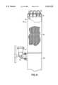
- FIG. 5is a partial cut-away view of an elevation of the regenerable acid scrubber according to the invention.
- FIG. 6is a diagram of an apparatus comprising the thermal reactor, particle removal chamber and regenerable acid scrubber.
- An inlet pressure monitoring port 12is shown.
- a bend 16 in the inletprovides optimum mixing of the gases.
- the inlet tubecontinues pass the reactor wall 17, terminating with an extension 18 of the inlet tube.
- the mixed gasesexit the extension 18, however not directly into the reactor volume, but instead into a concentric tube 19.
- the temperature of the mixture of gases and gas floware selected such that the flame is produced entirely within the tube 19. This provides for use of multiple inlets, each with slightly different gas mixtures, combustion temperatures and flame size as shown in FIG. 1.
- a second inlet 20is shown adjacent to inlet 10.
- Inlet 21is shown for introducing air between the inlet tubes at the reactor chamber.
- a third inlet 14is provided for introducing oxygen.
- the separate inletspermit control of oxidation, reduce the probability of incompatible gas stream mixing and permit active inlet pressure control independent of these parameters being utilized at adjacent inlets.
- FIG. 2there is shown a second embodiment of an inlet 30, also having a bend 31 downstream from the nitrogen inlet 32 which facilitates mixture of the process gases.
- An inlet pressure control port 33is provided.
- a vertical nitrogen stream inlet 34is provided downstream of the bend 31 to force gases into the extension 35 which passes through the reactor wall 36.
- the extension 35is surrounded by a concentric tube 37 to isolate the process gas from adjacent inlets.
- Process gasenters through inlets (not shown) at the top of the reactor into the central chamber 40.
- Annular heating elements 41are electrically heated to provide high temperature hot surfaces on the interior wall 42. Heated air is introduced into the upper portion of the reactor chamber 40 as indicated by arrows 43 through orifices 44 in the interior wall 42.
- Airis provided through the air inlet 45 into an exterior heating space formed between the exterior wall 46 and the heating elements 41.
- the air downwardly flows along the surface of the heating elementsthen upwardly flows along the interior heating space defined by the heating elements 41 and interior wall 42.
- the heated airexits into the upper portion of the reactor chamber 40 through the orifices 44.
- the interior and exterior heated spaces along the annular heatersare isolated from each other by a seal 47.
- the reacted gasesexit the reactor at the bottom of chamber 40 into a vortex of cooling water (not shown). Typically the gases are cooled to a temperature of less than 100° C. by the water vortex.
- a particle removal chamber 50there is shown a particle removal chamber 50.
- the gases from the thermal reactorare introduced through conduit 51 and passed through a water spray 52 and into a packed bed containing packing 53 (shown in partial cut-away view) through which the gases are flowed in both a co-current and counter-current manner through the packing with and against the flow of water provided by intermittent sprayer 54 and continuous sprayer 55.
- Particle-containing liquidflows to the bottom to a sump tank 56.
- Airis injected through port 57 to provide direct gas cooling and promote water vapor condensation. Water vapor condensing on small particles increases their size. These particles of a size greater than about 1 micron are removed by being flowed through the packed bed at low velocities.
- a regenerative chemical scrubberaccording to the present invention.
- the purpose of the scrubberis to treat the effluent gases to lower certain components below the threshold limit value (TLV).
- the gases to be treated in the scrubberenter through the plenum 60.
- the gasesflow upwardly through the scrubber 61 comprising two separate dry packed beds 62.
- the sprayers 63introduce a reagent to the top of the packed beds 62.
- the reagentcoats the packing material and entraps or reacts with the reactant target gases.
- the reagentis introduced to both beds 62 alternately. Some of the reagent is retained and coats the packing material and the excess drains into a recirculation tank (not shown) past plenum 60.
- the scrubberis intended to remove the reactant gases from the gas stream by both flow of gas counter to the reagent flow and co-current flow of reagent and entrapped pollutants.
- the treated effluent gasexits through flue 64 and the liquid containing the removed chemicals drains out the bottom of the scrubber past plenum 60. It is a feature of the scrubber to have at least two separate packed beds 62 so that when the chemical coating on the packing material becomes depleted in one bed, the coating may be replenished while the other bed is still operable. In this manner, the scrubber may be continuously operated.
- the process gas from one or more stations of semiconductor manufacturing plant 200enters the inlets 70, and is mixed, if required, with hydrogen through inlets 71, oxygen through inlets 72 and with an inert purge gas, such as nitrogen through inlets 73.
- the capacity of the facilitywill depend upon the size of hardware components, types of process gases and reagents, etc. Typical gas flow rates through the facility are less than about 600 slm.
- the gasesare then treated in the thermal reactor 74, to which air is introduced through lines 75.
- the gases exiting the bottom of thermal reactor 74pass through a vortex of water flowing through line 76 then through a water spray 77 into the particle removal chamber 78.
- Airis introduced into the particle removed chamber through line 79 and water is sprayed onto the packed bed through lines 80 and 81.
- the liquid effluent from the packed bed 78is collected in sump 82 and discarded through line 83 or recirculated through line 84 using respective pumps 85 and 86.
- Reagentsmay also be added to sump 82 through line 87.
- the recirculated fluids from sump 82are cooled at heat exchanger 89 before being recirculated to the top of the particle removal chamber 78.
- the treated gasesare then flowed through conduit 88 through a spray 90 of reagent from sump 82 then into plenum 91 to the regenerative chemical scrubber 92. After treatment in the scrubber the completely treated gases exit through stack 93.
- Reagent from the chemical scrubber 92is collected in tank 94 and can be recirculated via line 95 and pump 96 to the chemical scrubber 92.
- a fresh reagent for the chemical scrubbermay be held in tank 97 and added as needed through line 98 to tank 94.
- a detector 99is located in the stack 93 to monitor components intended to be removed in the scrubber. When the detector registers the TLV of a component in the gas, the reagent in tank 94 may be removed by automatic control via line 95 and fresh reagent added from tank 97 via line 98. This replacement of reagent may also be automatically controlled by a timer 100 to control replacement of reagent in tank 94 after predetermined periods of use.
- each of three typical perfluorinated compounds (PFC) present in semiconductor process gaseswere tested.
- the abatement achieved(measured as % DRE, decomposition removal efficiency) and NOx formation, based on 10% utilization of the PFC of the wafer process tool, were measured.
- the optimum gas flow rate(in standard liters/min, slm) and hydrogen gas addition at the reactor inlet are given to achieve the indicated DRE.
- a regenerative acid scrubber as shown in FIG. 5is tested using potassium hydroxide (50% w/w) as the scrubbing reagent.
- the scrubberis tested for process gases from four theoretical tools, used 20 hours/day, having the following flow rates/tool: BCl 3 125 sccm; Cl 2 50 sccm; CHF 3 60 sccm; CF 4 60 sccm.
- the KOH consumptionis 1 kg/day and estimated storage lifetime of the KOH solution is about 50 days.
- the lifetime of storage for solid KOHis about 35 days.
- the concentration of KOH in the scrubbing reagentwill be in the range of 50% to 10%. The reagent is replaced when the KOH concentration falls below 10%.
Landscapes
- Engineering & Computer Science (AREA)
- Environmental & Geological Engineering (AREA)
- Chemical & Material Sciences (AREA)
- General Engineering & Computer Science (AREA)
- Mechanical Engineering (AREA)
- Chemical Kinetics & Catalysis (AREA)
- Health & Medical Sciences (AREA)
- Biomedical Technology (AREA)
- Analytical Chemistry (AREA)
- General Chemical & Material Sciences (AREA)
- Oil, Petroleum & Natural Gas (AREA)
- Treating Waste Gases (AREA)
- Gas Separation By Absorption (AREA)
Abstract
Description
______________________________________ % Pump Purge H2 Addition NOx Formation Gas DRE (slm) (slm) (kg/year) ______________________________________ NF.sub.3 >99.999 10-100 2-20 <0.0064.sup.1 C2F.sub.6 >99.9 10-70 2-12 <0.0064.sup.1 CF.sub.4 >90 10-45 10-45.sup.2 0.22 ______________________________________ .sup.1 This is the detection limit of NOx for the mass spectrometer. .sup.2 Oxygen is also added at the inlet.
Claims (1)
Priority Applications (7)
| Application Number | Priority Date | Filing Date | Title |
|---|---|---|---|
| US09/005,856US6153150A (en) | 1998-01-12 | 1998-01-12 | Apparatus and method for controlled decomposition oxidation of gaseous pollutants |
| PCT/US1999/000616WO1999034899A1 (en) | 1998-01-12 | 1999-01-12 | Apparatus and method for controlled decomposition oxidation of gaseous pollutants |
| US09/228,706US6464944B1 (en) | 1998-01-12 | 1999-01-12 | Apparatus and method for controlled decomposition oxidation of gaseous pollutants |
| TW088100400ATW458803B (en) | 1998-01-12 | 1999-06-21 | Apparatus and method for controlled decomposition oxidation of gaseous pollutants |
| US09/892,729US6511641B2 (en) | 1998-01-12 | 2001-06-27 | Method for abatement of gaseous pollutants |
| US09/991,822US7138096B2 (en) | 1998-01-12 | 2001-11-06 | Method for decomposition oxidation of gaseous pollutants |
| US11/586,069US7790120B2 (en) | 1998-01-12 | 2006-10-25 | Apparatus and method for controlled decomposition oxidation of gaseous pollutants |
Applications Claiming Priority (1)
| Application Number | Priority Date | Filing Date | Title |
|---|---|---|---|
| US09/005,856US6153150A (en) | 1998-01-12 | 1998-01-12 | Apparatus and method for controlled decomposition oxidation of gaseous pollutants |
Related Child Applications (1)
| Application Number | Title | Priority Date | Filing Date |
|---|---|---|---|
| US09/228,706Continuation-In-PartUS6464944B1 (en) | 1998-01-12 | 1999-01-12 | Apparatus and method for controlled decomposition oxidation of gaseous pollutants |
Publications (1)
| Publication Number | Publication Date |
|---|---|
| US6153150Atrue US6153150A (en) | 2000-11-28 |
Family
ID=21718086
Family Applications (4)
| Application Number | Title | Priority Date | Filing Date |
|---|---|---|---|
| US09/005,856Expired - LifetimeUS6153150A (en) | 1998-01-12 | 1998-01-12 | Apparatus and method for controlled decomposition oxidation of gaseous pollutants |
| US09/228,706Expired - LifetimeUS6464944B1 (en) | 1998-01-12 | 1999-01-12 | Apparatus and method for controlled decomposition oxidation of gaseous pollutants |
| US09/991,822Expired - LifetimeUS7138096B2 (en) | 1998-01-12 | 2001-11-06 | Method for decomposition oxidation of gaseous pollutants |
| US11/586,069Expired - LifetimeUS7790120B2 (en) | 1998-01-12 | 2006-10-25 | Apparatus and method for controlled decomposition oxidation of gaseous pollutants |
Family Applications After (3)
| Application Number | Title | Priority Date | Filing Date |
|---|---|---|---|
| US09/228,706Expired - LifetimeUS6464944B1 (en) | 1998-01-12 | 1999-01-12 | Apparatus and method for controlled decomposition oxidation of gaseous pollutants |
| US09/991,822Expired - LifetimeUS7138096B2 (en) | 1998-01-12 | 2001-11-06 | Method for decomposition oxidation of gaseous pollutants |
| US11/586,069Expired - LifetimeUS7790120B2 (en) | 1998-01-12 | 2006-10-25 | Apparatus and method for controlled decomposition oxidation of gaseous pollutants |
Country Status (3)
| Country | Link |
|---|---|
| US (4) | US6153150A (en) |
| TW (1) | TW458803B (en) |
| WO (1) | WO1999034899A1 (en) |
Cited By (22)
| Publication number | Priority date | Publication date | Assignee | Title |
|---|---|---|---|---|
| WO2001037985A1 (en)* | 1999-11-26 | 2001-05-31 | Advanced Technology Materials, Inc. | In-situ air oxidation treatment of mocvd process effluent |
| US20020025286A1 (en)* | 2000-08-30 | 2002-02-28 | Gravley Rodrick J. | System, method and product-by-process for treatment of exhaust gases |
| US20020110500A1 (en)* | 1998-01-12 | 2002-08-15 | Moore Robert R. | Apparatus and method for controlled decomposition oxidation of gaseous pollutants |
| US20020182131A1 (en)* | 2001-06-01 | 2002-12-05 | Applied Materials, Inc. | Heated catalytic treatment of an effluent gas from a substrate fabrication process |
| US6527828B2 (en)* | 2001-03-19 | 2003-03-04 | Advanced Technology Materials, Inc. | Oxygen enhanced CDA modification to a CDO integrated scrubber |
| US6530977B2 (en)* | 2000-03-03 | 2003-03-11 | The Boc Group Plc | Abatement of semiconductor processing gases |
| US6551381B2 (en)* | 2001-07-23 | 2003-04-22 | Advanced Technology Materials, Inc. | Method for carbon monoxide reduction during thermal/wet abatement of organic compounds |
| US6596054B2 (en)* | 2001-07-23 | 2003-07-22 | Advanced Technology Materials, Inc. | Method for carbon monoxide reduction during thermal/wet abatement of organic compounds |
| US6627162B1 (en)* | 2000-05-22 | 2003-09-30 | Tsong-Maw Chen | Apparatus for treating waste gas from semiconductor manufacturing process |
| US6638343B1 (en)* | 1998-12-01 | 2003-10-28 | Ebara Corporation | Exhaust gas treating device |
| US20050147548A1 (en)* | 2004-01-05 | 2005-07-07 | Shiban Samir S. | Combined chemical agent and dynamic oxidation treatment of hazardous gas |
| US20050196330A1 (en)* | 2004-03-05 | 2005-09-08 | Ronald Garnett | Abatement device |
| US20050201913A1 (en)* | 2004-03-10 | 2005-09-15 | Shiban Samir S. | Hazardous gas abatement system using electrical heater and water scrubber |
| US7569193B2 (en) | 2003-12-19 | 2009-08-04 | Applied Materials, Inc. | Apparatus and method for controlled combustion of gaseous pollutants |
| US7700049B2 (en) | 2005-10-31 | 2010-04-20 | Applied Materials, Inc. | Methods and apparatus for sensing characteristics of the contents of a process abatement reactor |
| US7736599B2 (en) | 2004-11-12 | 2010-06-15 | Applied Materials, Inc. | Reactor design to reduce particle deposition during process abatement |
| US20110195001A1 (en)* | 2008-02-12 | 2011-08-11 | Shiban Samir S | Dynamic oxidation of process gas |
| JP2016011759A (en)* | 2014-06-27 | 2016-01-21 | 日本パイオニクス株式会社 | Exhaust gas combustion purification system |
| US20160146458A1 (en)* | 2013-07-17 | 2016-05-26 | Edwards Limited | A head assembly for a radiant burner |
| KR20180048901A (en)* | 2015-09-01 | 2018-05-10 | 에드워즈 리미티드 | Abatement device |
| US20230220994A1 (en)* | 2020-06-02 | 2023-07-13 | Csk Inc. | A scrubber burner |
| WO2025074176A1 (en)* | 2023-10-03 | 2025-04-10 | Edwards Vacuum Llc | Head unit for abatement apparatus and method of producing the head unit |
Families Citing this family (24)
| Publication number | Priority date | Publication date | Assignee | Title |
|---|---|---|---|---|
| US5955037A (en)* | 1996-12-31 | 1999-09-21 | Atmi Ecosys Corporation | Effluent gas stream treatment system having utility for oxidation treatment of semiconductor manufacturing effluent gases |
| US6843830B2 (en)* | 2003-04-15 | 2005-01-18 | Advanced Technology Materials, Inc. | Abatement system targeting a by-pass effluent stream of a semiconductor process tool |
| KR100517408B1 (en)* | 2003-07-03 | 2005-09-27 | 삼성전자주식회사 | Contamination control system and Air-conditioning system of substrate processing apparatus using the same |
| US20050172806A1 (en)* | 2004-02-10 | 2005-08-11 | Rodney Olson | Method and apparatus for filtering |
| US7565808B2 (en) | 2005-01-13 | 2009-07-28 | Greencentaire, Llc | Refrigerator |
| WO2007095150A2 (en)* | 2006-02-11 | 2007-08-23 | Applied Materials, Inc. | Methods and apparatus for pfc abatement using a cdo chamber |
| DE102006052586B4 (en)* | 2006-11-08 | 2008-07-03 | Schott Solar Gmbh | Method and device for cleaning the exhaust gases of a silicon thin-film production plant |
| US7726135B2 (en) | 2007-06-06 | 2010-06-01 | Greencentaire, Llc | Energy transfer apparatus and methods |
| US8123843B2 (en)* | 2007-10-17 | 2012-02-28 | Dow Global Technologies Llc | Rich gas absorption apparatus and method |
| US20090222128A1 (en)* | 2008-02-05 | 2009-09-03 | Applied Materials, Inc. | Methods and apparatus for operating an electronic device manufacturing system |
| KR101581673B1 (en)* | 2008-02-05 | 2015-12-31 | 어플라이드 머티어리얼스, 인코포레이티드 | Systems and methods for treating flammable effluent gases from manufacturing processes |
| US20090200005A1 (en)* | 2008-02-09 | 2009-08-13 | Sullivan Shaun E | Energy transfer tube apparatus, systems, and methods |
| DE102008037418B3 (en)* | 2008-10-07 | 2010-02-18 | Reicat Gmbh | Process for the purification of exhaust gases by generative afterburning |
| DE102008052644A1 (en)* | 2008-10-22 | 2010-04-29 | Volkswagen Ag | Method for thermal subsequent treatment of exhaust air of drying chamber, involves supplying exhaust air to burner device and exhaust gas of burner device to recuperation device for keeping moderate temperature of drying chamber |
| US20100143222A1 (en)* | 2008-11-10 | 2010-06-10 | Phil Chandler | Exhaust condensate removal apparatus for abatement system |
| US20110212010A1 (en)* | 2009-09-02 | 2011-09-01 | Despatch Industries Limited Partnership | Apparatus and Method for Thermal Destruction of Volatile Organic Compounds |
| BR112013013082B8 (en) | 2010-11-26 | 2022-06-28 | Potter Owen | GAS PARTICLE PROCESSOR AND METHOD FOR PROCESSING GAS PARTICLE |
| GB2504468B (en) | 2012-07-27 | 2017-03-22 | Edwards Ltd | Burner Nozzle Reciprocating Scraper Arrangement for Reducing Effluent Gas Deposits |
| GB201505447D0 (en)* | 2015-03-30 | 2015-05-13 | Edwards Ltd | Radiant burner |
| CN111315971B (en)* | 2017-07-07 | 2021-12-10 | 鉴锋国际股份有限公司 | Device for controlling decomposition and oxidation of gas pollutants |
| DE102021103365B4 (en)* | 2021-02-12 | 2024-02-15 | Das Environmental Expert Gmbh | Process and burner for the thermal disposal of pollutants in process gases |
| GB2604652A (en)* | 2021-03-12 | 2022-09-14 | Edwards Ltd | Abatement apparatus |
| KR102418089B1 (en) | 2021-04-22 | 2022-07-07 | 엠에이티플러스 주식회사 | Flameless Catalyst Thermal Oxydizer |
| GB2608821A (en)* | 2021-07-13 | 2023-01-18 | Edwards Ltd | Inlet assembly |
Citations (32)
| Publication number | Priority date | Publication date | Assignee | Title |
|---|---|---|---|---|
| US3691729A (en)* | 1970-05-30 | 1972-09-19 | Stamicarbon | Process and apparatus for the recovery of ammonia and carbon dioxide from the tail gas of a urea synthesis |
| US3780675A (en)* | 1972-04-18 | 1973-12-25 | Boardman Co | Plasma arc refuse disintegrator |
| US3902853A (en)* | 1973-04-06 | 1975-09-02 | Ethyl Corp | Exhaust reactor |
| US4280982A (en)* | 1978-03-23 | 1981-07-28 | Mamoru Shindome | Apparatus for treating waste material while preventing smelt-water explosions |
| EP0057878A1 (en)* | 1981-01-30 | 1982-08-18 | Union Carbide Corporation | Coating substrates with high solids compositions |
| US4420462A (en)* | 1982-03-22 | 1983-12-13 | Clyde Robert A | Catalytic heat exchanger |
| US4443228A (en)* | 1982-06-29 | 1984-04-17 | Texaco Inc. | Partial oxidation burner |
| US4509456A (en)* | 1981-07-28 | 1985-04-09 | Veb Zentrum Fur Forschung Und Technologie Mikroelektronik | Apparatus for guiding gas for LP CVD processes in a tube reactor |
| US4719088A (en)* | 1985-02-12 | 1988-01-12 | Mitsubish Denki Kabushiki Kaisha | Apparatus for removing at least one acidic component from a gas |
| EP0346893A1 (en)* | 1988-06-15 | 1989-12-20 | Centrotherm Elektrische Anlagen Gmbh + Co. | Apparatus for purifying exhaust gases emitted in CVD processes |
| EP0347753A1 (en)* | 1988-06-15 | 1989-12-27 | Centrotherm Elektrische Anlagen Gmbh + Co. | Process for purifying waste gazes from CVD-processes |
| WO1990014184A2 (en)* | 1989-05-24 | 1990-11-29 | Centrotherm Elektrische Anlagen Gmbh + Co. | Continuous furnace |
| US4981722A (en)* | 1988-08-12 | 1991-01-01 | Veb Elektromat Dresden | Apparatus for the gas-phase processing of disk-shaped workpieces |
| US5011520A (en)* | 1989-12-15 | 1991-04-30 | Vector Technical Group, Inc. | Hydrodynamic fume scrubber |
| US5037624A (en)* | 1987-03-24 | 1991-08-06 | Advanced Technology Materials Inc. | Composition, apparatus, and process, for sorption of gaseous compounds of group II-VII elements |
| US5151395A (en)* | 1987-03-24 | 1992-09-29 | Novapure Corporation | Bulk gas sorption and apparatus, gas containment/treatment system comprising same, and sorbent composition therefor |
| US5156827A (en)* | 1989-03-14 | 1992-10-20 | Advanced Technology Materials, Inc. | Apparatus, process, and composition for in-situ generation of polyhydridic compounds of group iv-vi elements |
| US5277026A (en)* | 1992-02-22 | 1994-01-11 | Mercedes-Benz Ag | Internal combustion engine exhaust system |
| WO1994021968A1 (en)* | 1993-03-25 | 1994-09-29 | Gaz De France | Process for the treatment of hot and polluted gas issued from a thermal reactor including a combustion |
| US5407646A (en)* | 1989-12-05 | 1995-04-18 | The University Of Toronto Innovations Foundation | Dual impeller method and apparatus for effecting chemical conversion |
| US5427746A (en)* | 1994-03-08 | 1995-06-27 | W. R. Grace & Co.-Conn. | Flow modification devices for reducing emissions from thermal voc oxidizers |
| WO1995018674A1 (en)* | 1994-01-10 | 1995-07-13 | Atmi Ecosys Corporation | Metallo-oxomeric scrubber compositions, and method of gas purification utilizing same |
| WO1996000076A1 (en)* | 1994-06-23 | 1996-01-04 | Chiroscience Limited | Use of the enantiomers of oxazophosphorines, e.g. ifosfamide, in anti-tumour therapy, for reducing side-effects |
| US5518528A (en)* | 1994-10-13 | 1996-05-21 | Advanced Technology Materials, Inc. | Storage and delivery system for gaseous hydride, halide, and organometallic group V compounds |
| WO1996023173A1 (en)* | 1995-01-23 | 1996-08-01 | Centrotherm Elektrische Anlagen Gmbh + Co. | Waste gas purification device |
| US5554347A (en)* | 1994-02-02 | 1996-09-10 | Institut Francais Du Petrole | Apparatus for carrying out chemical reactions requiring addition of heat at least during start up |
| US5614156A (en)* | 1995-02-08 | 1997-03-25 | Wang; Chi S. | Ultra-pyrolysis reactor for hazardous waste destruction |
| US5622682A (en)* | 1994-04-06 | 1997-04-22 | Atmi Ecosys Corporation | Method for concentration and recovery of halocarbons from effluent gas streams |
| US5643538A (en)* | 1994-05-24 | 1997-07-01 | Institut Francais Du Petrole | Heat transfer and thermal cleaning rotary device applied to gaseous effluents |
| WO1997030275A1 (en)* | 1996-02-15 | 1997-08-21 | Atmi Ecosys Corporation | Point-of-use catalytic oxidation apparatus and method for treatment of voc-containing gas streams |
| US5676712A (en)* | 1995-05-16 | 1997-10-14 | Atmi Ecosys Corporation | Flashback protection apparatus and method for suppressing deflagration in combustion-susceptible gas flows |
| US5800792A (en)* | 1994-11-29 | 1998-09-01 | Teisan Kabushiki Kaisha | Exhaust gas treatment unit and method |
Family Cites Families (17)
| Publication number | Priority date | Publication date | Assignee | Title |
|---|---|---|---|---|
| US3462250A (en)* | 1964-07-07 | 1969-08-19 | Montedison Spa | Process and apparatus for the partial combustion of liquid hydrocarbons to gaseous mixtures containing hydrogen and carbon monoxide |
| FR2633934B1 (en) | 1988-07-07 | 1994-09-09 | Comp Generale Electricite | CORROSION INHIBITOR FOR AQUEOUS LIQUID USED FOR COOLING CIRCUITS, ESPECIALLY THOSE OF INTERNAL COMBUSTION ENGINES |
| US5183646A (en)* | 1989-04-12 | 1993-02-02 | Custom Engineered Materials, Inc. | Incinerator for complete oxidation of impurities in a gas stream |
| US5384108A (en)* | 1989-04-24 | 1995-01-24 | Mallinckrodt Medical, Inc. | Magnetic resonance imaging agents |
| US5510093A (en) | 1994-07-25 | 1996-04-23 | Alzeta Corporation | Combustive destruction of halogenated compounds |
| JP4011116B2 (en)* | 1995-06-06 | 2007-11-21 | ビーピー・コーポレーション・ノース・アメリカ・インコーポレーテッド | Catalytic exhaust gas treatment system for reduction of volatile chemical emissions |
| US5919425A (en)* | 1995-09-21 | 1999-07-06 | Engelhard Corporation | Catalyzed packing material for regenerative catalytic oxidation |
| JP3486022B2 (en)* | 1995-10-16 | 2004-01-13 | ジャパン・エア・ガシズ株式会社 | Exhaust gas treatment equipment |
| US5649985A (en)* | 1995-11-29 | 1997-07-22 | Kanken Techno Co., Ltd. | Apparatus for removing harmful substances of exhaust gas discharged from semiconductor manufacturing process |
| KR0172185B1 (en)* | 1996-01-23 | 1999-02-18 | 김경균 | Apparatus and method for treating harmful waste gases |
| JP3815815B2 (en) | 1996-01-31 | 2006-08-30 | 株式会社ルネサステクノロジ | Semiconductor device manufacturing method and exhaust gas treatment apparatus |
| US5873388A (en)* | 1996-06-07 | 1999-02-23 | Atmi Ecosys Corporation | System for stabilization of pressure perturbations from oxidation systems for treatment of process gases from semiconductor manufacturing operations |
| US5759498A (en)* | 1996-12-12 | 1998-06-02 | United Microelectronics Corp. | Gas exhaust apparatus |
| WO1998046334A1 (en) | 1997-04-16 | 1998-10-22 | Ebara Corporation | Method for removing nitrogen oxides in exhaust gas |
| US6153150A (en)* | 1998-01-12 | 2000-11-28 | Advanced Technology Materials, Inc. | Apparatus and method for controlled decomposition oxidation of gaseous pollutants |
| US6261524B1 (en)* | 1999-01-12 | 2001-07-17 | Advanced Technology Materials, Inc. | Advanced apparatus for abatement of gaseous pollutants |
| AU2003286558A1 (en)* | 2002-10-24 | 2004-05-13 | Optical Solutions, Inc. | Passive optical network address association recovery |
- 1998
- 1998-01-12USUS09/005,856patent/US6153150A/ennot_activeExpired - Lifetime
- 1999
- 1999-01-12USUS09/228,706patent/US6464944B1/ennot_activeExpired - Lifetime
- 1999-01-12WOPCT/US1999/000616patent/WO1999034899A1/enactiveApplication Filing
- 1999-06-21TWTW088100400Apatent/TW458803B/ennot_activeIP Right Cessation
- 2001
- 2001-11-06USUS09/991,822patent/US7138096B2/ennot_activeExpired - Lifetime
- 2006
- 2006-10-25USUS11/586,069patent/US7790120B2/ennot_activeExpired - Lifetime
Patent Citations (32)
| Publication number | Priority date | Publication date | Assignee | Title |
|---|---|---|---|---|
| US3691729A (en)* | 1970-05-30 | 1972-09-19 | Stamicarbon | Process and apparatus for the recovery of ammonia and carbon dioxide from the tail gas of a urea synthesis |
| US3780675A (en)* | 1972-04-18 | 1973-12-25 | Boardman Co | Plasma arc refuse disintegrator |
| US3902853A (en)* | 1973-04-06 | 1975-09-02 | Ethyl Corp | Exhaust reactor |
| US4280982A (en)* | 1978-03-23 | 1981-07-28 | Mamoru Shindome | Apparatus for treating waste material while preventing smelt-water explosions |
| EP0057878A1 (en)* | 1981-01-30 | 1982-08-18 | Union Carbide Corporation | Coating substrates with high solids compositions |
| US4509456A (en)* | 1981-07-28 | 1985-04-09 | Veb Zentrum Fur Forschung Und Technologie Mikroelektronik | Apparatus for guiding gas for LP CVD processes in a tube reactor |
| US4420462A (en)* | 1982-03-22 | 1983-12-13 | Clyde Robert A | Catalytic heat exchanger |
| US4443228A (en)* | 1982-06-29 | 1984-04-17 | Texaco Inc. | Partial oxidation burner |
| US4719088A (en)* | 1985-02-12 | 1988-01-12 | Mitsubish Denki Kabushiki Kaisha | Apparatus for removing at least one acidic component from a gas |
| US5037624A (en)* | 1987-03-24 | 1991-08-06 | Advanced Technology Materials Inc. | Composition, apparatus, and process, for sorption of gaseous compounds of group II-VII elements |
| US5151395A (en)* | 1987-03-24 | 1992-09-29 | Novapure Corporation | Bulk gas sorption and apparatus, gas containment/treatment system comprising same, and sorbent composition therefor |
| EP0346893A1 (en)* | 1988-06-15 | 1989-12-20 | Centrotherm Elektrische Anlagen Gmbh + Co. | Apparatus for purifying exhaust gases emitted in CVD processes |
| EP0347753A1 (en)* | 1988-06-15 | 1989-12-27 | Centrotherm Elektrische Anlagen Gmbh + Co. | Process for purifying waste gazes from CVD-processes |
| US4981722A (en)* | 1988-08-12 | 1991-01-01 | Veb Elektromat Dresden | Apparatus for the gas-phase processing of disk-shaped workpieces |
| US5156827A (en)* | 1989-03-14 | 1992-10-20 | Advanced Technology Materials, Inc. | Apparatus, process, and composition for in-situ generation of polyhydridic compounds of group iv-vi elements |
| WO1990014184A2 (en)* | 1989-05-24 | 1990-11-29 | Centrotherm Elektrische Anlagen Gmbh + Co. | Continuous furnace |
| US5407646A (en)* | 1989-12-05 | 1995-04-18 | The University Of Toronto Innovations Foundation | Dual impeller method and apparatus for effecting chemical conversion |
| US5011520A (en)* | 1989-12-15 | 1991-04-30 | Vector Technical Group, Inc. | Hydrodynamic fume scrubber |
| US5277026A (en)* | 1992-02-22 | 1994-01-11 | Mercedes-Benz Ag | Internal combustion engine exhaust system |
| WO1994021968A1 (en)* | 1993-03-25 | 1994-09-29 | Gaz De France | Process for the treatment of hot and polluted gas issued from a thermal reactor including a combustion |
| WO1995018674A1 (en)* | 1994-01-10 | 1995-07-13 | Atmi Ecosys Corporation | Metallo-oxomeric scrubber compositions, and method of gas purification utilizing same |
| US5554347A (en)* | 1994-02-02 | 1996-09-10 | Institut Francais Du Petrole | Apparatus for carrying out chemical reactions requiring addition of heat at least during start up |
| US5427746A (en)* | 1994-03-08 | 1995-06-27 | W. R. Grace & Co.-Conn. | Flow modification devices for reducing emissions from thermal voc oxidizers |
| US5622682A (en)* | 1994-04-06 | 1997-04-22 | Atmi Ecosys Corporation | Method for concentration and recovery of halocarbons from effluent gas streams |
| US5643538A (en)* | 1994-05-24 | 1997-07-01 | Institut Francais Du Petrole | Heat transfer and thermal cleaning rotary device applied to gaseous effluents |
| WO1996000076A1 (en)* | 1994-06-23 | 1996-01-04 | Chiroscience Limited | Use of the enantiomers of oxazophosphorines, e.g. ifosfamide, in anti-tumour therapy, for reducing side-effects |
| US5518528A (en)* | 1994-10-13 | 1996-05-21 | Advanced Technology Materials, Inc. | Storage and delivery system for gaseous hydride, halide, and organometallic group V compounds |
| US5800792A (en)* | 1994-11-29 | 1998-09-01 | Teisan Kabushiki Kaisha | Exhaust gas treatment unit and method |
| WO1996023173A1 (en)* | 1995-01-23 | 1996-08-01 | Centrotherm Elektrische Anlagen Gmbh + Co. | Waste gas purification device |
| US5614156A (en)* | 1995-02-08 | 1997-03-25 | Wang; Chi S. | Ultra-pyrolysis reactor for hazardous waste destruction |
| US5676712A (en)* | 1995-05-16 | 1997-10-14 | Atmi Ecosys Corporation | Flashback protection apparatus and method for suppressing deflagration in combustion-susceptible gas flows |
| WO1997030275A1 (en)* | 1996-02-15 | 1997-08-21 | Atmi Ecosys Corporation | Point-of-use catalytic oxidation apparatus and method for treatment of voc-containing gas streams |
Cited By (38)
| Publication number | Priority date | Publication date | Assignee | Title |
|---|---|---|---|---|
| US7790120B2 (en) | 1998-01-12 | 2010-09-07 | Applied Materials, Inc. | Apparatus and method for controlled decomposition oxidation of gaseous pollutants |
| US20070041879A1 (en)* | 1998-01-12 | 2007-02-22 | Moore Robert R | Apparatus and method for controlled decomposition oxidation of gaseous pollutants |
| US20020110500A1 (en)* | 1998-01-12 | 2002-08-15 | Moore Robert R. | Apparatus and method for controlled decomposition oxidation of gaseous pollutants |
| US6464944B1 (en)* | 1998-01-12 | 2002-10-15 | Advanced Technology Materials, Inc. | Apparatus and method for controlled decomposition oxidation of gaseous pollutants |
| US7138096B2 (en) | 1998-01-12 | 2006-11-21 | Applied Materials, Inc. | Method for decomposition oxidation of gaseous pollutants |
| US6638343B1 (en)* | 1998-12-01 | 2003-10-28 | Ebara Corporation | Exhaust gas treating device |
| WO2001037985A1 (en)* | 1999-11-26 | 2001-05-31 | Advanced Technology Materials, Inc. | In-situ air oxidation treatment of mocvd process effluent |
| US6491884B1 (en) | 1999-11-26 | 2002-12-10 | Advanced Technology Materials, Inc. | In-situ air oxidation treatment of MOCVD process effluent |
| US6530977B2 (en)* | 2000-03-03 | 2003-03-11 | The Boc Group Plc | Abatement of semiconductor processing gases |
| US6627162B1 (en)* | 2000-05-22 | 2003-09-30 | Tsong-Maw Chen | Apparatus for treating waste gas from semiconductor manufacturing process |
| US20020025286A1 (en)* | 2000-08-30 | 2002-02-28 | Gravley Rodrick J. | System, method and product-by-process for treatment of exhaust gases |
| US6527828B2 (en)* | 2001-03-19 | 2003-03-04 | Advanced Technology Materials, Inc. | Oxygen enhanced CDA modification to a CDO integrated scrubber |
| US20020182131A1 (en)* | 2001-06-01 | 2002-12-05 | Applied Materials, Inc. | Heated catalytic treatment of an effluent gas from a substrate fabrication process |
| US6824748B2 (en) | 2001-06-01 | 2004-11-30 | Applied Materials, Inc. | Heated catalytic treatment of an effluent gas from a substrate fabrication process |
| US6596054B2 (en)* | 2001-07-23 | 2003-07-22 | Advanced Technology Materials, Inc. | Method for carbon monoxide reduction during thermal/wet abatement of organic compounds |
| US6551381B2 (en)* | 2001-07-23 | 2003-04-22 | Advanced Technology Materials, Inc. | Method for carbon monoxide reduction during thermal/wet abatement of organic compounds |
| US7569193B2 (en) | 2003-12-19 | 2009-08-04 | Applied Materials, Inc. | Apparatus and method for controlled combustion of gaseous pollutants |
| US20050147548A1 (en)* | 2004-01-05 | 2005-07-07 | Shiban Samir S. | Combined chemical agent and dynamic oxidation treatment of hazardous gas |
| US7488460B2 (en) | 2004-01-05 | 2009-02-10 | Innovative Engineering Solutions, Inc. | Combined chemical agent and dynamic oxidation treatment of hazardous gas |
| US20050196330A1 (en)* | 2004-03-05 | 2005-09-08 | Ronald Garnett | Abatement device |
| US20050201913A1 (en)* | 2004-03-10 | 2005-09-15 | Shiban Samir S. | Hazardous gas abatement system using electrical heater and water scrubber |
| US20050276739A1 (en)* | 2004-03-10 | 2005-12-15 | Innovative Engineering Solutions, Inc. | Hazardous gas abatement system using electrical heater and water scrubber |
| US7534399B2 (en) | 2004-03-10 | 2009-05-19 | Innovative Engineering Solutions, Inc. | Hazardous gas abatement system using electrical heater and water scrubber |
| US7601307B2 (en) | 2004-03-10 | 2009-10-13 | Innovative Engineering Solutions, Inc. | Hazardous gas abatement system using electrical heater and water scrubber |
| US7736599B2 (en) | 2004-11-12 | 2010-06-15 | Applied Materials, Inc. | Reactor design to reduce particle deposition during process abatement |
| US7985379B2 (en) | 2004-11-12 | 2011-07-26 | Applied Materials, Inc. | Reactor design to reduce particle deposition during process abatement |
| US7700049B2 (en) | 2005-10-31 | 2010-04-20 | Applied Materials, Inc. | Methods and apparatus for sensing characteristics of the contents of a process abatement reactor |
| US7736600B2 (en) | 2005-10-31 | 2010-06-15 | Applied Materials, Inc. | Apparatus for manufacturing a process abatement reactor |
| US20110195001A1 (en)* | 2008-02-12 | 2011-08-11 | Shiban Samir S | Dynamic oxidation of process gas |
| US8192693B2 (en) | 2008-02-12 | 2012-06-05 | Innovative Engineering Solutions, Inc. | Apparatus for dynamic oxidation of process gas |
| US8562930B2 (en) | 2008-02-12 | 2013-10-22 | Innovative Engineering Solutions, Inc. | Dynamic oxidation of process gas |
| US11162676B2 (en)* | 2013-07-17 | 2021-11-02 | Edwards Limited | Head assembly for a radiant burner |
| US20160146458A1 (en)* | 2013-07-17 | 2016-05-26 | Edwards Limited | A head assembly for a radiant burner |
| JP2016011759A (en)* | 2014-06-27 | 2016-01-21 | 日本パイオニクス株式会社 | Exhaust gas combustion purification system |
| JP2018526608A (en)* | 2015-09-01 | 2018-09-13 | エドワーズ リミテッド | Abatement equipment |
| KR20180048901A (en)* | 2015-09-01 | 2018-05-10 | 에드워즈 리미티드 | Abatement device |
| US20230220994A1 (en)* | 2020-06-02 | 2023-07-13 | Csk Inc. | A scrubber burner |
| WO2025074176A1 (en)* | 2023-10-03 | 2025-04-10 | Edwards Vacuum Llc | Head unit for abatement apparatus and method of producing the head unit |
Also Published As
| Publication number | Publication date |
|---|---|
| WO1999034899A1 (en) | 1999-07-15 |
| US20070041879A1 (en) | 2007-02-22 |
| TW458803B (en) | 2001-10-11 |
| US6464944B1 (en) | 2002-10-15 |
| US7790120B2 (en) | 2010-09-07 |
| US20020110500A1 (en) | 2002-08-15 |
| US7138096B2 (en) | 2006-11-21 |
Similar Documents
| Publication | Publication Date | Title |
|---|---|---|
| US6153150A (en) | Apparatus and method for controlled decomposition oxidation of gaseous pollutants | |
| US6511641B2 (en) | Method for abatement of gaseous pollutants | |
| KR100847915B1 (en) | Exhaust gas stream processing apparatus and method for oxidizing exhaust gas during semiconductor manufacturing | |
| US7641867B2 (en) | Apparatus for processing perfluorocarbon | |
| US7972582B2 (en) | Method and apparatus for treating exhaust gas | |
| US20090010814A1 (en) | Effluent gas stream treatment system having utility for oxidation treatment of semiconductor manufacturing effluent gases | |
| JP4211467B2 (en) | Catalytic exhaust gas treatment device and exhaust gas treatment method | |
| WO1998029181A1 (en) | Effluent gas stream treatment system for oxidation treatment of semiconductor manufacturing effluent gases | |
| US20040101460A1 (en) | Apparatus and method for point-of-use treatment of effluent gas streams | |
| JP4218618B2 (en) | Exhaust gas decomposition treatment equipment | |
| US20050175524A1 (en) | Method and apparatus for treating exhaust gas | |
| WO1992014098A1 (en) | High-tech computerized containment and treatment apparatus and process for combustion off-gas | |
| US8231851B2 (en) | Method for processing perfluorocarbon, and apparatus therefor | |
| WO2001008786A1 (en) | Method and apparatus for catalytic conversion of fluorinated compounds in gases |
Legal Events
| Date | Code | Title | Description |
|---|---|---|---|
| AS | Assignment | Owner name:DELATECH, INC., CALIFORNIA Free format text:ASSIGNMENT OF ASSIGNORS INTEREST;ASSIGNORS:MOORE, ROBERT;GETTY, JAMES;SAFIULLIN, RAVIL;REEL/FRAME:009200/0198 Effective date:19980319 | |
| AS | Assignment | Owner name:ADVANCED TECHNOLOGY MATERIALS, INC., CONNECTICUT Free format text:ASSIGNMENT OF ASSIGNORS INTEREST;ASSIGNOR:ATMI ECOSYS CORPORATION;REEL/FRAME:011165/0684 Effective date:20001005 | |
| STCF | Information on status: patent grant | Free format text:PATENTED CASE | |
| AS | Assignment | Owner name:ADVANCED TECHNOLOGY MATERIALS, INC., CONNECTICUT Free format text:ASSIGNMENT OF ASSIGNORS INTEREST;ASSIGNOR:DELATECH INCORPORATED;REEL/FRAME:011296/0853 Effective date:20001114 | |
| FPAY | Fee payment | Year of fee payment:4 | |
| AS | Assignment | Owner name:APPLIED MATERIALS, INC., CALIFORNIA Free format text:ASSIGNMENT OF ASSIGNORS INTEREST;ASSIGNOR:ADVANCED TECHNOLOGY MATERIALS, INC.;REEL/FRAME:016937/0211 Effective date:20041216 | |
| FPAY | Fee payment | Year of fee payment:8 | |
| FEPP | Fee payment procedure | Free format text:PAT HOLDER CLAIMS SMALL ENTITY STATUS, ENTITY STATUS SET TO SMALL (ORIGINAL EVENT CODE: LTOS); ENTITY STATUS OF PATENT OWNER: SMALL ENTITY | |
| AS | Assignment | Owner name:BHT SERVICES PTE. LTD., SINGAPORE Free format text:ASSIGNMENT OF ASSIGNORS INTEREST;ASSIGNOR:APPLIED MATERIALS, INC.;REEL/FRAME:028045/0762 Effective date:20111212 | |
| FPAY | Fee payment | Year of fee payment:12 | |
| SULP | Surcharge for late payment | Year of fee payment:11 |