US6152899A - Expandable catheter having improved electrode design, and method for applying energy - Google Patents
Expandable catheter having improved electrode design, and method for applying energyDownload PDFInfo
- Publication number
- US6152899A US6152899AUS08/895,850US89585097AUS6152899AUS 6152899 AUS6152899 AUS 6152899AUS 89585097 AUS89585097 AUS 89585097AUS 6152899 AUS6152899 AUS 6152899A
- Authority
- US
- United States
- Prior art keywords
- arms
- catheter
- energy application
- interconnecting
- application devices
- Prior art date
- Legal status (The legal status is an assumption and is not a legal conclusion. Google has not performed a legal analysis and makes no representation as to the accuracy of the status listed.)
- Expired - Lifetime
Links
Images


Classifications
- A—HUMAN NECESSITIES
- A61—MEDICAL OR VETERINARY SCIENCE; HYGIENE
- A61B—DIAGNOSIS; SURGERY; IDENTIFICATION
- A61B18/00—Surgical instruments, devices or methods for transferring non-mechanical forms of energy to or from the body
- A61B18/04—Surgical instruments, devices or methods for transferring non-mechanical forms of energy to or from the body by heating
- A61B18/12—Surgical instruments, devices or methods for transferring non-mechanical forms of energy to or from the body by heating by passing a current through the tissue to be heated, e.g. high-frequency current
- A61B18/14—Probes or electrodes therefor
- A61B18/1492—Probes or electrodes therefor having a flexible, catheter-like structure, e.g. for heart ablation
- A—HUMAN NECESSITIES
- A61—MEDICAL OR VETERINARY SCIENCE; HYGIENE
- A61B—DIAGNOSIS; SURGERY; IDENTIFICATION
- A61B17/00—Surgical instruments, devices or methods
- A61B17/00008—Vein tendon strippers
- A—HUMAN NECESSITIES
- A61—MEDICAL OR VETERINARY SCIENCE; HYGIENE
- A61B—DIAGNOSIS; SURGERY; IDENTIFICATION
- A61B17/00—Surgical instruments, devices or methods
- A61B17/22—Implements for squeezing-off ulcers or the like on inner organs of the body; Implements for scraping-out cavities of body organs, e.g. bones; for invasive removal or destruction of calculus using mechanical vibrations; for removing obstructions in blood vessels, not otherwise provided for
- A61B2017/22051—Implements for squeezing-off ulcers or the like on inner organs of the body; Implements for scraping-out cavities of body organs, e.g. bones; for invasive removal or destruction of calculus using mechanical vibrations; for removing obstructions in blood vessels, not otherwise provided for with an inflatable part, e.g. balloon, for positioning, blocking, or immobilisation
- A—HUMAN NECESSITIES
- A61—MEDICAL OR VETERINARY SCIENCE; HYGIENE
- A61B—DIAGNOSIS; SURGERY; IDENTIFICATION
- A61B17/00—Surgical instruments, devices or methods
- A61B17/22—Implements for squeezing-off ulcers or the like on inner organs of the body; Implements for scraping-out cavities of body organs, e.g. bones; for invasive removal or destruction of calculus using mechanical vibrations; for removing obstructions in blood vessels, not otherwise provided for
- A61B2017/22097—Valve removal in veins
- A—HUMAN NECESSITIES
- A61—MEDICAL OR VETERINARY SCIENCE; HYGIENE
- A61B—DIAGNOSIS; SURGERY; IDENTIFICATION
- A61B18/00—Surgical instruments, devices or methods for transferring non-mechanical forms of energy to or from the body
- A61B2018/00005—Cooling or heating of the probe or tissue immediately surrounding the probe
- A61B2018/00011—Cooling or heating of the probe or tissue immediately surrounding the probe with fluids
- A61B2018/00029—Cooling or heating of the probe or tissue immediately surrounding the probe with fluids open
- A—HUMAN NECESSITIES
- A61—MEDICAL OR VETERINARY SCIENCE; HYGIENE
- A61B—DIAGNOSIS; SURGERY; IDENTIFICATION
- A61B18/00—Surgical instruments, devices or methods for transferring non-mechanical forms of energy to or from the body
- A61B2018/00053—Mechanical features of the instrument of device
- A61B2018/00059—Material properties
- A61B2018/00071—Electrical conductivity
- A61B2018/00083—Electrical conductivity low, i.e. electrically insulating
- A—HUMAN NECESSITIES
- A61—MEDICAL OR VETERINARY SCIENCE; HYGIENE
- A61B—DIAGNOSIS; SURGERY; IDENTIFICATION
- A61B18/00—Surgical instruments, devices or methods for transferring non-mechanical forms of energy to or from the body
- A61B2018/00053—Mechanical features of the instrument of device
- A61B2018/00107—Coatings on the energy applicator
- A61B2018/00154—Coatings on the energy applicator containing and delivering drugs
- A—HUMAN NECESSITIES
- A61—MEDICAL OR VETERINARY SCIENCE; HYGIENE
- A61B—DIAGNOSIS; SURGERY; IDENTIFICATION
- A61B18/00—Surgical instruments, devices or methods for transferring non-mechanical forms of energy to or from the body
- A61B2018/00053—Mechanical features of the instrument of device
- A61B2018/00214—Expandable means emitting energy, e.g. by elements carried thereon
- A61B2018/0022—Balloons
- A—HUMAN NECESSITIES
- A61—MEDICAL OR VETERINARY SCIENCE; HYGIENE
- A61B—DIAGNOSIS; SURGERY; IDENTIFICATION
- A61B18/00—Surgical instruments, devices or methods for transferring non-mechanical forms of energy to or from the body
- A61B2018/00053—Mechanical features of the instrument of device
- A61B2018/00214—Expandable means emitting energy, e.g. by elements carried thereon
- A61B2018/00267—Expandable means emitting energy, e.g. by elements carried thereon having a basket shaped structure
- A—HUMAN NECESSITIES
- A61—MEDICAL OR VETERINARY SCIENCE; HYGIENE
- A61B—DIAGNOSIS; SURGERY; IDENTIFICATION
- A61B18/00—Surgical instruments, devices or methods for transferring non-mechanical forms of energy to or from the body
- A61B2018/00053—Mechanical features of the instrument of device
- A61B2018/00273—Anchoring means for temporary attachment of a device to tissue
- A61B2018/00279—Anchoring means for temporary attachment of a device to tissue deployable
- A61B2018/00285—Balloons
- A—HUMAN NECESSITIES
- A61—MEDICAL OR VETERINARY SCIENCE; HYGIENE
- A61B—DIAGNOSIS; SURGERY; IDENTIFICATION
- A61B18/00—Surgical instruments, devices or methods for transferring non-mechanical forms of energy to or from the body
- A61B2018/00315—Surgical instruments, devices or methods for transferring non-mechanical forms of energy to or from the body for treatment of particular body parts
- A61B2018/00345—Vascular system
- A61B2018/00404—Blood vessels other than those in or around the heart
- A—HUMAN NECESSITIES
- A61—MEDICAL OR VETERINARY SCIENCE; HYGIENE
- A61B—DIAGNOSIS; SURGERY; IDENTIFICATION
- A61B18/00—Surgical instruments, devices or methods for transferring non-mechanical forms of energy to or from the body
- A61B2018/00315—Surgical instruments, devices or methods for transferring non-mechanical forms of energy to or from the body for treatment of particular body parts
- A61B2018/00482—Digestive system
- A61B2018/00488—Esophagus
- A—HUMAN NECESSITIES
- A61—MEDICAL OR VETERINARY SCIENCE; HYGIENE
- A61B—DIAGNOSIS; SURGERY; IDENTIFICATION
- A61B18/00—Surgical instruments, devices or methods for transferring non-mechanical forms of energy to or from the body
- A61B2018/00636—Sensing and controlling the application of energy
- A61B2018/00696—Controlled or regulated parameters
- A61B2018/00702—Power or energy
- A—HUMAN NECESSITIES
- A61—MEDICAL OR VETERINARY SCIENCE; HYGIENE
- A61B—DIAGNOSIS; SURGERY; IDENTIFICATION
- A61B18/00—Surgical instruments, devices or methods for transferring non-mechanical forms of energy to or from the body
- A61B2018/00636—Sensing and controlling the application of energy
- A61B2018/00696—Controlled or regulated parameters
- A61B2018/00744—Fluid flow
- A—HUMAN NECESSITIES
- A61—MEDICAL OR VETERINARY SCIENCE; HYGIENE
- A61B—DIAGNOSIS; SURGERY; IDENTIFICATION
- A61B18/00—Surgical instruments, devices or methods for transferring non-mechanical forms of energy to or from the body
- A61B2018/00636—Sensing and controlling the application of energy
- A61B2018/00696—Controlled or regulated parameters
- A61B2018/00755—Resistance or impedance
- A—HUMAN NECESSITIES
- A61—MEDICAL OR VETERINARY SCIENCE; HYGIENE
- A61B—DIAGNOSIS; SURGERY; IDENTIFICATION
- A61B18/00—Surgical instruments, devices or methods for transferring non-mechanical forms of energy to or from the body
- A61B2018/00636—Sensing and controlling the application of energy
- A61B2018/00773—Sensed parameters
- A61B2018/00791—Temperature
- A61B2018/00797—Temperature measured by multiple temperature sensors
- A—HUMAN NECESSITIES
- A61—MEDICAL OR VETERINARY SCIENCE; HYGIENE
- A61B—DIAGNOSIS; SURGERY; IDENTIFICATION
- A61B18/00—Surgical instruments, devices or methods for transferring non-mechanical forms of energy to or from the body
- A61B2018/00636—Sensing and controlling the application of energy
- A61B2018/00773—Sensed parameters
- A61B2018/00791—Temperature
- A61B2018/00821—Temperature measured by a thermocouple
- A—HUMAN NECESSITIES
- A61—MEDICAL OR VETERINARY SCIENCE; HYGIENE
- A61B—DIAGNOSIS; SURGERY; IDENTIFICATION
- A61B18/00—Surgical instruments, devices or methods for transferring non-mechanical forms of energy to or from the body
- A61B2018/00636—Sensing and controlling the application of energy
- A61B2018/00773—Sensed parameters
- A61B2018/00875—Resistance or impedance
- A—HUMAN NECESSITIES
- A61—MEDICAL OR VETERINARY SCIENCE; HYGIENE
- A61B—DIAGNOSIS; SURGERY; IDENTIFICATION
- A61B18/00—Surgical instruments, devices or methods for transferring non-mechanical forms of energy to or from the body
- A61B18/04—Surgical instruments, devices or methods for transferring non-mechanical forms of energy to or from the body by heating
- A61B18/12—Surgical instruments, devices or methods for transferring non-mechanical forms of energy to or from the body by heating by passing a current through the tissue to be heated, e.g. high-frequency current
- A61B18/1206—Generators therefor
- A61B2018/1246—Generators therefor characterised by the output polarity
- A61B2018/1253—Generators therefor characterised by the output polarity monopolar
- A—HUMAN NECESSITIES
- A61—MEDICAL OR VETERINARY SCIENCE; HYGIENE
- A61B—DIAGNOSIS; SURGERY; IDENTIFICATION
- A61B18/00—Surgical instruments, devices or methods for transferring non-mechanical forms of energy to or from the body
- A61B18/04—Surgical instruments, devices or methods for transferring non-mechanical forms of energy to or from the body by heating
- A61B18/12—Surgical instruments, devices or methods for transferring non-mechanical forms of energy to or from the body by heating by passing a current through the tissue to be heated, e.g. high-frequency current
- A61B18/1206—Generators therefor
- A61B2018/1246—Generators therefor characterised by the output polarity
- A61B2018/126—Generators therefor characterised by the output polarity bipolar
- A—HUMAN NECESSITIES
- A61—MEDICAL OR VETERINARY SCIENCE; HYGIENE
- A61B—DIAGNOSIS; SURGERY; IDENTIFICATION
- A61B18/00—Surgical instruments, devices or methods for transferring non-mechanical forms of energy to or from the body
- A61B18/04—Surgical instruments, devices or methods for transferring non-mechanical forms of energy to or from the body by heating
- A61B18/12—Surgical instruments, devices or methods for transferring non-mechanical forms of energy to or from the body by heating by passing a current through the tissue to be heated, e.g. high-frequency current
- A61B18/14—Probes or electrodes therefor
- A61B2018/1465—Deformable electrodes
- A—HUMAN NECESSITIES
- A61—MEDICAL OR VETERINARY SCIENCE; HYGIENE
- A61B—DIAGNOSIS; SURGERY; IDENTIFICATION
- A61B18/00—Surgical instruments, devices or methods for transferring non-mechanical forms of energy to or from the body
- A61B18/04—Surgical instruments, devices or methods for transferring non-mechanical forms of energy to or from the body by heating
- A61B18/12—Surgical instruments, devices or methods for transferring non-mechanical forms of energy to or from the body by heating by passing a current through the tissue to be heated, e.g. high-frequency current
- A61B18/14—Probes or electrodes therefor
- A61B2018/1497—Electrodes covering only part of the probe circumference
Definitions
- the inventionrelates generally to catheters and more particularly, to expandable catheters having electrodes for applying energy to biological tissue, and methods therefor.
- the venous systemcontains a plurality of valves for directing blood flow back to the heart.
- the venous system of the lower limbconsists essentially of the superficial venous system and the deep venous system with perforating veins connecting the two systems.
- the superficial systemincludes the great saphenous vein and the small saphenous vein.
- the deep venous systemincludes the anterior and posterior tibial veins which unite to form the popliteal vein which in turn becomes the femoral vein when joined by the small saphenous vein.
- FIG. 1there is shown a partial cross-sectional view of a dilated vein 10 from a lower limb having competent valves 12.
- Venous valvesare usually bicuspid valves, with each cusp forming a sack or reservoir 16 for blood which, under pressure, forces the free edges of the cusps together to prevent retrograde flow of the blood and allow only antegrade flow to the deep veins and heart.
- the arrow 18 leading out the top of the veinrepresents the antegrade flow of blood back to the heart.
- Properly operating venous valvesprevent retrograde flow as blood is pushed forward through the vein lumen and back to the heart.
- Venous insufficiencyis a chronic disease involving the incompetence of venous valves.
- Chronic venous insufficiencyis a problem caused by hydrodynamic forces acting on the lowest part of the body: the legs, ankles and feet.
- the retrograde flow of bloodmay occur and the valves in the veins become less able to withstand the weight of the blood above them.
- the weight of the bloodcauses the veins to dilate further and the valves in the veins to fail.
- Localized incompetence of a valve in a perforator veinallows reflux of blood from the deep venous system to the superficial venous system. Reflux may be expressed as the peak reverse velocity of blood as a function of vein diameter.
- Patients with phlebitismay have damaged vein valve leaflets.
- the varicose vein conditionincludes dilation and tortuosity of the superficial veins of the lower limbs, resulting in unsightly discoloration, pain, swelling, and possibly ulceration.
- Varicose veinsoften involve incompetence of one or more venous valves, which allow reflux of blood within the superficial system. This can also be worsened by deep venous reflux and perforator reflux.
- Current treatmentsinclude surgical procedures such as vein stripping, ligation, and occasionally, vein segment transplant, venous valvuloplasty, and the implantation of various prosthetic devices. The removal of varicose veins from the body can be a tedious, time-consuming procedure having a painful and slow healing process.
- varicose veinsmay undergo injection sclerotherapy, or removal of vein segments. Complications, scarring, and the loss of the vein for future cardiac and other by-pass procedures may also result.
- varicose veinsmay persist or recur, particularly when the valvular problem is not corrected. Due to the long, technically demanding nature of the surgical valve reconstruction procedure, treating multiple venous sections with surgical venous valve repair is rarely performed. Thus, a complete treatment of all important incompetent valves has been impractical.
- Venous insufficiencyoften consists of hypertension of the lower limb in the deep, perforating and often superficial veins.
- Existing treatments for chronic venous insufficiencyare often less than ideal. These treatments include the elevation of the legs, compressing the veins externally with elastic support hose, perforator ligation, surgical valve repair, and grafting vein sections with healthy valves from the arm into the leg. These methods have variable effectiveness.
- invasive surgeryhas its associated complications with risk to life and expense.
- the palliative therapiesrequire major lifestyle changes for the patient. For example, the ulcers may recur unless the patient continues to elevate the legs and use pressure gradient stockings for long continuous periods of time.
- ligation of vascular lumina by cauterization or coagulation using electrical energy from an electrodehas been employed as an alternative to the surgical removal of superficial and perforator veins.
- ligation proceduresalso close off the lumen, essentially destroying its functional capability.
- a probeis forced through the subcutaneous layer between the fascia and the skin, and then to the vein to be destroyed.
- a monopolar electrode at the outer end of the probeis placed adjacent the varicose vein and the return electrode is placed on the skin.
- an alternating current of 500 kHzis applied to destroy the adjacent varicose vein by electrocoagulation.
- the coagulated veinloses the function of allowing blood to flow through, and is no longer of use. For example, occluding or ligating the saphenous vein would render that vein unavailable for harvesting in other surgical procedures such as coronary by-pass operations.
- Catheters having bowable or expandable arms with electrodes mounted on the armsmay be used to apply energy to the inside surface of a hollow anatomical structure.
- shrinking a veinit is desirable to apply energy evenly around the entire inner surface of the vein at the treatment location so that the full inner surface is evenly heated. The evenly-heated surface should then contract more uniformly to shrink the vein diameter.
- To apply energy to the vein wallit is preferable to bring a plurality of evenly-spaced electrodes into apposition with the vein tissue. It is also preferable to use electrodes that are as wide as possible as the wider sized electrodes will be closer together when in apposition with the vein wall and will result in a more even application of energy to the vein wall.
- a consideration applicable to expandable cathetersis the avoidance of fluid leakage into the catheter around movable parts. Another consideration is the avoidance of catheter distortion through use of those movable parts. For example, operating the expansion mechanism to control the expansion and contraction of the expandable arms may subject the catheter shaft to axial stresses that tend to undesirably lengthen or compress the catheter shaft. At the same time, it is desirable to maintain catheter shaft flexibility.
- the present inventionprovides a minimally invasive apparatus and method for solving the underlying problems of venous insufficiency and uses a novel repair system, including an energy delivery catheter for applying energy to a selected tissue site. Additionally, the present invention is useful for shrinking other hollow anatomical structures.
- a bowable electrode catheterto apply energy to a selected hollow anatomical structure.
- the bowable electrode catheterapplies energy to restore the competence of venous valves, normalize flow patterns, dynamics, and pressure; reduce sections of dilated varicose veins to a normal diameter for cosmetic purposes, and treat veins such that they remain patent in that their valves can resume their function and return blood to the heart.
- One feature of the present inventionis to provide such an apparatus for applying energy to cause shrinkage of a hollow anatomical structure, comprising a catheter having a shaft, an outer diameter and a working end, wherein the outer diameter of the catheter is less than the inner diameter of the hollow anatomical structure.
- a plurality of electrodesare located at the working end, two of which are connected together at a common electrically conductive device, for single point wire attachment. The plurality of electrodes produce an energy field to heat a treatment area adjacent the electrodes to cause preferential shrinkage of the hollow anatomical structure.
- ring membersfor mechanically and electrically interconnecting electrodes to provide single wire contacts for transmitting energy while obtaining precise, even spacing between the electrodes.
- electrodesare mounted on tapered arms, the tapers allowing more room between the arms at their mounting points to the catheter body. At the same time, mounting the arms to the catheter body is made easier.
- Another feature of the present inventionis a temperature sensor for measuring temperatures at the electrode.
- an openingis formed in the electrode to receive the sensor, the opening having an oval or slot shape so that there remains sufficient electrode material between the sensor and the side of the electrode to retain electrode mechanical strength. This feature reduces the possibility of electrode fracture due to repeated expansion and contraction and increases the attachment strength of the sensor to the electrode.
- the openingis adapted to result in more reliable sensor potting and a less bulky profile.
- the sensor wiresare located on either side of the electrode.
- An additional aspect of the present inventionis a tension wire located in the catheter shaft to prevent elongation of the catheter during electrode expansion.
- a further feature of the present inventionis to provide an outer tube having a spring coil enclosed in a polymer to form the outer shaft of the catheter for reducing axial compressibility while increasing flexibility.
- Another feature of the present inventionis to provide means for automatically detecting a fluid flush, sensing temperature changes resulting therefrom, and controlling the application of power to avoid undesired cycling.
- Yet a further aspect of the present inventionis to apply an external pressure exerting device to the treatment area sufficient to compress the hollow anatomical structure to the desired diameter before the application of energy.
- the present inventionfurther includes a method of applying energy to cause shrinkage of a hollow anatomical structure, the method comprising the steps of introducing a catheter having a working end with bowable electrodes for applying energy to the hollow anatomical structure.
- the methodalso includes the step of mechanically and electrically interconnecting the electrodes to result in fewer wires and greater precision in spacing the electrodes from one another.
- FIG. 1is a cross-section view of a portion of a vein in a lower limb showing a segment of the vein having dilation with multiple incompetent valves which are to be treated in accordance with the present invention and a segment of the vein having fully competent valves;
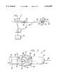
- FIG. 2is a diagram of an RF energy system with a catheter having expandable electrodes for imparting energy to treat a vein;
- FIG. 3is an enlarged side view of the working end of the embodiment of the catheter shown in FIG. 2 showing the expandable arms and electrodes in an expanded position, temperature sensors, guide wire, and stop surface arrangement, in accordance with aspects of the present invention
- FIG. 4is a view similar to FIG. 3 showing the expandable arms and electrodes in a contracted position
- FIGS. 5A and 5Bpresent schematic views of the distances between electrodes in the contracted position of FIG. 4 and in the expanded position of FIG. 3;
- FIG. 6is an enlarged perspective view of an embodiment of expandable arms with common ring connectors in accordance with an aspect of the present invention
- FIG. 6ais an enlarged perspective view of another embodiment of expanded arms with common ring connectors
- FIG. 7is a partially cut-away perspective view of a tube having an enclosed coiled spring
- FIG. 8is an enlarged cross-section view of a tension wire embedded in the working end tip of the catheter shaft in accordance with an aspect of the present invention
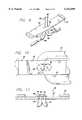
- FIG. 9is an enlarged view of the formation of a thermocouple sensor in a slot at an electrode, in accordance with an aspect of the invention.
- FIG. 10is a top plan partly-fragmentary, partly-sectional enlarged view of the thermocouple of FIG. 9 showing the routing of the thermocouple wires in accordance with an aspect of the present invention
- FIG. 11is a cross-sectional enlarged view of a thermocouple temperature sensor formed in an electrode, in accordance with the present invention.
- FIG. 12is a view of the application of a pressure device to the lower limb of a patient
- FIG. 13is a schematic, cross-sectional view of a vein valve compressed into coaptation by the external compressive forces of the pressure device of FIG. 12 and the treatment of that valve by a catheter device;
- FIG. 14is a flow chart illustrating the operation of the system of FIG. 2 in response to the introduction of a fluid flush.
- FIG. 15is a partial cross-sectional view of the use of a catheter to treat an incompetent venous valve.
- FIGS. 2 and 3an apparatus for minimally invasive treatment of venous insufficiency and valvular incompetency that includes a catheter 20 for delivering electrodes 22 to a venous treatment site.
- the catheter 20further includes a working end 24, which includes electrodes 22 on expandable arms 26, a shaft 28, a working end tip 30, and a handle or connecting end 32.
- the catheter 20includes four conductive arms 26 although only three can be seen. The arms 26 can be expanded or bent or bowed outward as shown.
- the arms 26are formed of an electrically conductive material such as stainless steel, spring steel, or a shape memory material such as that commonly referred to as NitinolTM. To restrict energy transmission to the desired portion of the arm 26, i.e., to the electrode 22, the arms 26 are surrounded by insulation, except for the exposed conductive surface area that serves as the electrode.
- the electrode 22 of the arm 26may be formed by cutting the insulation layer away with a laser or by other means.
- the insulation on the arms 26may comprise parylene applied by vapor deposition, PET that is shrunk over the arms or coated on the arms, polyimide that is shrunk over the arms, polyurethane that is coated on the arms, or another type of application process or insulating material that may be deposited in a vacuum chamber, extruded, heat shrunk, or otherwise applied onto the arms 26.
- the insulationis also provided along the inner surfaces of the expandable arms 26 away from the electrodes 22 and further covers the peripheral edges of the exposed face of the electrode 22 to prevent heating the blood flowing in the vein and reduce the likelihood of coagulation.
- working endwill refer to the direction toward the treatment site in the patient
- connecting endwill refer to the direction away from the treatment site in the patient.
- the following embodimentsare directed to the treatment of the venous system of the lower limbs. It is to be understood, however, that the invention is not limited thereto and can be employed intraluminally to treat other biological structures, as is discussed below.
- the expandable arms 26may be fabricated so that they are biased to return to the reduced diameter profile shown in FIG. 4.
- the use of metal arms 26results in such biasing.
- the armsmay have a thickness ranging from 0.13 mm to 1.27 mm and preferably between 0.38 mm and 0.76 mm, to allow four or more electrodes around the catheter shaft.
- Rounded wiresmay also be used with a diameter preferably between about 0.13 mm to 0.38 mm, but can be up to about 0.76 mm.
- the expandable arms 26are preferably tapered at each end 34, such that there is a larger electrode surface area 22 located at the midpoint between the two ends 34.
- the smaller ends 34reduce the possibility of contact with the ends of other arms at their mounting points in the catheter and leave more room for wiring temperature sensors mounted to the arms, as is described below in greater detail.
- the center width of the arms 26 in the embodiment shownis 0.76 mm with the arms symmetrically tapering to a width of 0.38 mm at both ends 34.
- the lengths of the arms 26range from 30.5 mm to 32.5 mm, and the thickness ranges from 0.10 to 0.12 mm.
- FIG. 5Apresents a schematic of the positions of the electrodes when the expandable arms are in their contracted configuration, and demonstrates the spacing "X" between the electrodes 22.
- the spacing between the electrodes 22increases to the much greater spacing "Y” as seen in FIG. 5B, which is also a schematic view that shows the positions of the electrodes when the arms are in their expanded positions.
- the current and power densitiesdecrease as the distance between electrodes increases and thus, the current and power densities along the "Y" distance are less than along the "X” distance.
- using tapered arms in accordance with the embodiment described above wherein the electrodes are located at the greatest width of the armswill result in those electrodes being closer together by that width. This results in increased current and power densities.
- FIG. 6a configuration used to reduce the number of wires and the wiring complexity in the working end 24 of the catheter (FIGS. 2 and 3) as well as make placement of the arms 26 more even and increase manufacturing ease is shown.
- Sets of expandable armsare commonly attached, or formed, on a connecting strip or ring.
- the connecting ringis electrically conductive as are the arms and therefore, only one electrical attachment is necessary to each set of arms.
- a first set of three expandable arms 40is attached to a first common connecting ring 42.
- a second set of three expandable arms 44is attached to a second common connecting ring 46. Both sets of arms have their respective expandable arms spaced equidistantly from one another at 120°.
- the second set of armsis rotated relative to the first set so that there is 60° between adjacent arms in the combined sets of arms.
- the first and second sets of expandable arms 40 and 44each consists of half of the total number thereof.
- the first and second ringseach have a single electrical conductor 48 and 50 respectively attached to the inside surfaces to provide power to the ring and the associated arms, with their electrodes. In a bipolar application, one conductor would be connected to the positive polarity and the other connected to the negative polarity.
- the electrode ringshave, for example, a 1.5 mm inside diameter and a 1.6 mm outside diameter, and are 1.0 mm thick. In one embodiment, they are formed of silver-plated stainless steel.
- first ring 42 and second ring 46have their arms attached to the outside of their respective rings. While the arms of one may touch the ring of the other, electrical contact is avoided due to the insulation on the arms. The arms overlap the rings by approximately 0.5 mm and are held in place.
- connection of the arms 40 and 44 to the rings 42 and 46may be accomplished by spot welding or alternatively may be accomplished by soldering or through the use of an electrically conductive adhesive.
- Such a connectionmay also be made by forming the ring of one continuous strip or piece of material, where the arms are tabs on the strip that may be bent down into place from a central disk or they may be formed by other means.
- the other, non-interconnected ends of the armsare, in this embodiment, held in place on a catheter shaft by adhesive, such as epoxy. A sleeve is then placed over these ends of the arms in tight contact with the arm ends and the epoxy. This is described in further detail below.
- the use of the common connector rings 42 and 46results in less wiring through the catheter shaft 28 and at the working end tip 30 of the catheter allowing the catheter to be made smaller. Fewer connections and parts result in increased reliability as well. Manufacturing is made easier as the placement of the arms in relation to each other is accomplished outside the catheter. Greater precision in the spacing of the arms is possible as well as ease in manufacturing because the catheter need not be handled as the arms are welded into position. The greater precision in the spacing of the arms resulting from the use of the connector rings 42 and 46 will result in a more even application of energy to the wall of the hollow anatomical structure and a more even heating of that wall. More uniform current and power densities will be applied.
- armsmay be connected to a common connection ring, or a greater number, such as four.
- hollow anatomical structures with larger inner diametersare treated with a greater number of arms.
- the use of the ring with only two armsnevertheless results in less wiring at the working end of the catheter because each arm need not be wired separately.
- the armsneed not be equidistantly spaced about their respective rings. They may all be located on one side of a diametrical line for example, while a second ring has another set of arms located on the opposite side of the diametrical line. When the first and second rings are combined however, the arms would be equally spaced about the periphery.
- insulatione.g. parylene
- the rings 42 and 46are mounted in the catheter at the working end tip 30 in this embodiment with the non-interconnected ends of the arms pointing towards the connecting end.
- both ends of the armsmay be connected to interconnecting rings.
- Such an arrangementwould provide even greater control over the spacing of the arms in that both ends of each arm would be precisely located and spaced from the other arms. This arrangement would result in even greater precision of that spacing.
- the armsmay be mounted to interconnecting rings that are located at the connecting end side of the working end. The non-interconnected ends of the arms would, in this case, be pointing towards the working end tip 30.
- the electrical wiremay be connected to an arm at the working end tip and because of the interconnecting ring providing an electrical path among its respective arms, all interconnected arms will be of the same polarity.
- the electrical wiresmay be connected to the arms in accordance with other schemes.
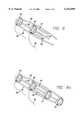
- the expandable arms 26are connected at their ends on the connecting end side of the working end to a slidable outer shaft or tube 52 under a connecting sleeve 36 and at their opposite ends to the rings 42 and 46 that are fixedly mounted in the working end tip 30 under a tip sleeve 38.
- the sleeves 36 and 38can be fabricated from polyimide.
- the sleeve 38not only provides a smooth transition from the outer shaft to the arms and vice versa, but also provides a redundant attachment of the arms to the catheter.
- the ends of the armsare attached to the catheter shaft by epoxy.
- the sleeve 38is tightly mounted over the arm ends and epoxy to also hold the arms to the shaft.
- the slidable outer tubecontrols the extent of the expansion of the arms 26 for proper treatment of vein lumina having different inner diameters.
- An inner stop tube 54is connected to the slidable tube 52 and moves with it, acting as a stop device by making contact with a stop surface 56 that is fixed in position to the working end tip 30. The inner stop tube 54 thus interacts with the stop surface 56 to limit the amount of expansion of the expandable arms 26.
- the slidable tube 52extends to the connecting end 32 and the arms 26 are in their contracted or collapsed positions.
- the tube 52causes the ends 34 of the expandable arms 26 to move closer together thus causing the center section of the arms, with their electrodes 22, to expand outwardly from the catheter shaft, as shown in FIGS. 2 and 3, to make contact with the vein wall.
- the electrodes 22are urged radially outward and inward, respectively.
- the working end tip 30essentially remains stationary while the outer slidable tube 52 is moved.
- the outer slidable tube 52may be moved a preset distance to cause the arms 26 to bow outwardly to a known diameter. Such known diameter or diameters may be indicated by gradients or other indicia placed on the actuator 58. By manipulating the slidable outer tube 52 to adjust the effective diameter of the electrodes 22, contact between the electrodes 22 and the venous tissue can be established and subsequently maintained during shrinkage.
- the control actuator 58may take the form of a sliding switch 59, a lever, a threaded control knob, or other suitable mechanism, preferably one that can provide fine control over the movement of slidable outer tube 52.
- the control actuator 58By using the control actuator 58 to move the tube 52, the effective diameter of the electrodes 22 can be closely controlled for treating vein lumina to provide varying degrees of vein shrinkage and precise control of the final desired diameter.
- the outer tube 52is preferably designed to minimize axial compressibility of the tube 52 in order to reduce the necessity for large movements by the actuator 58, and to prevent the undesired collapse of the expandable arms 26.
- the slidable outer tube 52 in one embodimentis made thicker to have increased column strength. In one case, its thickness was 0.05 mm. At this thickness, the axial compressibility of the tube 52 is reduced, lessening the need for a large lever or switch 59 motion at the handle, and preventing the arms 26 from collapsing.
- the slidable outer tube 52is made of a different material having a greater column strength, for example polyimide instead of polyethylene, and may or may not be thicker.
- the slidable outer tube 52may be formed of two or more coaxial tubes bonded together at their ends to form a thickened tube.
- the slidable outer tube 52may comprise an enclosed spring 60, as shown in FIG. 7 to reduce axial compressibility, provide more column strength when pulled and pushed, and yet allow for shaft flexibility.
- the polymer material that encloses the spring in the outer tube 52may comprise PET or polyethylene.
- the spring 60may be formed of stainless steel or other material.
- the sleeve 36 at the connecting end side of the working endprovides a smooth transition from the slidable tube 52 over the ends 34 of the expandable arms 26.
- the sleeve 36comprises a tapered portion to transition from the diameter of the slidable tube 52 to the arms 26.
- polyimide or preferably a softer material such as siliconewould serve as an intermediate step or diameter between the slidable tube 52 and the sleeve 36. If using a shrink tubing to form the transition, a PET is preferred because of its thin wall. Rather than heat shrunk, adhesive may be used to provide a smooth transition.
- a metal tension wire 62runs along the length of the inner shaft assembly and is anchored at each end to prevent elongation of the inner tube during expansion of the arms 26.
- the tension wire 62 and its termination at the connecting end and working endare partially shown in dashed lines in FIG. 2.
- the tension wire 62is terminated in a hook shape 63.
- the tension wire 62is wrapped around the lumen 64 twice between the two interconnecting rings 42 and 46.
- the tension wireis fully encapsulated or "potted” in adhesive fixing it to the catheter shaft.
- the wire 62was formed of stainless steel having a diameter of 0.25 mm. Materials other than stainless steel may be used for the tension wire 62 such as tungsten or other metals.
- the tension wire 62is placed in an off-center position to allow room for an axially-located lumen 64 that may be used for a guide wire or for conducting fluids.
- the end of the tension wireis shown wrapped around the lumen 64 at a position between the interconnecting rings 42 and 46 in the distal tip side of the working end.
- the tension wire 62may also be terminated in various other ways such as ending straight or soldered to a ring or washer before being potted into adhesive. Wires extended to the working end of the catheter from the connecting end may be wound around the tension wire 62, or the lumen 64, or both.
- the lumen 64can include a separate tubing having sufficient length to traverse the length of the catheter. As shown in FIG. 8, the tubing for the 64 lumen ends just after the tip sleeve 38 so that the remainder of the tip 30 can remain flexible.
- the tubing for the lumen 64can be fabricated from polyethylene.
- the lumen 64is surrounded by the two interconnecting rings 42 and 46, and the tension wire 62. The end of the tension wire is wrapped around the tubing of the lumen 64.
- the lead wires (not shown) for the electrical connections and thermocouplecan be set alongside the lumen 64.
- the tension wire 62 and the lead wiresare sandwiched between secondary sleeve 65 and the lumen 64.
- the stop sleeve 56is located between the secondary sleeve 65 and the tip sleeve 38.
- Epoxyfills the space between the lumen 64 and the tip sleeve 38, and the rings 42 and 46 and the tension wire 62 are fixed or potted into position.
- the sets of expandable arms 40 and 44exit the epoxy-filled sleeve to form the arms 26 of the electrode catheter.
- the flexible portion of the tip 30can be attached to the sleeve by an adhesive such as cyanoacrylate.
- a hook projecting from under the base of the first ring 42can engage the flexible portion of the tip to act as a secondary attachment and further secure the flexible portion in place.
- the hookcan be encapsulated under the ring 42 by adhesive or epoxy.
- a fluid sheath 66preferably taking the form of a bellows prevents fluids from entering the catheter.
- the bellows 66may comprise a plastic tube with its ends secured onto the working end of the inner stop tube 54 and to the stop surface 56, thereby preventing fluid from getting between the moving parts.
- the bellows 66folds up when sliding motion of the outer tube 52 over the inner shaft expands the expandable arms 26.
- the bellows 66may be blown in a mold or free-blown for initial expansion, and may be heat shrunk, press fit, or adhered with adhesive to its mounting surfaces to form a fluid-tight seal.
- a bellows 66is particularly useful in that it permits unrestricted movement of the slidable outer tube 52 yet seals the sliding parts from fluid leakage.
- the lumen 64has a size large enough to accept a guide wire 68 (FIG. 3).
- the lumen 64 through which the guide wire 68 passesis preferably insulated so as to prevent or minimize any coupling effect the electrodes 22 may have on the guide wire 68.
- the guide wire 68can be removed before the application of RF energy to the electrodes 22 to allow the guide wire lumen 64 to be used for the delivery or perfusion of medicant and cooling solution to the treatment area during the application of the RF energy.
- the working end tip 30can include a flexible nosecone shape, but can have other atraumatic shapes that facilitate tracking of the catheter 20 over the guide wire 68 and through bends in the venous vascular system of the patient.
- the nosecone-shaped tip 30can be fabricated from a flexible polymer having a soft durometer, such as 44 Shore A.
- the working end tip 30can be constructed from a spring covered with a thin layer of polyethylene shrink tubing.
- FIG. 3a system in accordance with aspects of the invention is shown.
- the electrodes 22 on the bowable arms 26are connected to an RF generator 74 controlled by a processor 76 which in this case, is a microprocessor located within the generator 74.
- the processor 76controls the RF generator 74 to apply energy to the electrodes 22 to generate heat in the target tissue.
- both the length of time that energy is applied and the level of that energymay be programmed.
- the embodiment of FIG. 3also includes a temperature sensor 78 mounted on each arm 26, in the electrode area 22 in this case.
- FIG. 3is not drawn to scale and the actual temperature sensor may be much smaller than that shown, such as that shown in FIG. 4, or smaller.
- Signals from the temperature sensors 78are coupled to the microprocessor 76 which compares them to a threshold temperature or temperatures to determine if RF energy to the electrodes 22 should be interrupted or should be continued.
- the microprocessor 76controls the RF generator 74 accordingly. Although shown as going through the RF generator 74 in FIG. 2, the signals from the temperature sensors 78 may be provided directly to the microprocessor 76 in a different embodiment. Temperature feedback permits control over the application of power to heat and thereby shrink the collagen effectively, as described below, without damaging surrounding tissue.
- thermocoupleSuch a sensor is shown in further detail in FIGS. 9, 10, and 11.
- a pair of wires 94 and 96are brought to a slot 84 in the electrode 22.
- the slot 84is of the form of an oval.
- the use of a longitudinally-oriented slot 84 in the electrode 22provides the benefit of increased strength of the electrode in that there remains a substantial amount of electrode material between the slot and the lateral edge of the electrode. This strengthens the electrode and makes it less susceptible to fractures that may otherwise be caused by repeated actuation.
- This shape of the slot 84also increases the attachment strength of the thermocouple to the electrode.
- solder mound 90is hemispheric in shape, as shown in FIG. 11, there is more electrode material under the solder mound making it a stronger attachment.
- the conductor portions 80 and 82 of the wiresare formed of thermocouple compatible materials, such as one wire 80 formed of copper and the other 82 formed of constantan.
- the conductors 80 and 82are brought together through the slot 84 and are welded together.
- Each wire 94 and 96has insulation 86 and 88 and each wire is pulled through the slot 84 until its insulation is touching the bottom of the arm 26 at the slot 84.
- the slot 84is made large enough for only the wires to pass but not their insulation.
- the two welded wires 80 and 82are soldered 90 in place in the slot 84.
- the solderforms the mound 90 on the opposite side of the slot from the insulation side.
- the mound 90secures the wires to the electrode and prevents the wires 94 and 96 from becoming detached.
- Connecting the two wires 94 and 96 as shown and describedresults in the formation of a thermocouple that provides signals representative of the temperature the electrode is experiencing.
- the insulationis removed 92 in the center of the arm 26 to form the electrode and for receipt of the temperature sensor.
- the thickness of the insulationis exaggerated in the figures for illustrative purposes only. Because the sensor 78 is small in comparison with the entire electrode surface area, it should allow for a large contact surface of the electrode to the target tissue.
- thermocouple wires 94 and 96leave the slot 84, they are disposed on either side of the expandable arm so as to provide equal weight on both sides of the arm and equal resistance to expansion and contraction of the arm. They are held in place on either side of each arm by the working end tip sleeve 38 (FIG. 3), as the rings 42 and 46 are.
- a bifilar or two-conductor wireis used for the thermocouple.
- the wiresproceed into the tip 30 located in relation to their respective expandable arm as shown in FIG. 10, and are bent in a 180° curve in the tip 30. They are potted in place in the tip 30 with epoxy or other material.
- the wiresare then wound around the lumen 64 as they proceed to the connecting end of the catheter. Locating them in this manner removes them from possible interference with the slidable outer tube 52 and stop tube 54 thus making the configuration more reliable.
- the wiresare not bonded to the outer diameter of the lumen 64.
- the slot 84 for the temperature sensormay have other shapes, such as a rectangle or circle. It is preferable that the slot be longer than it is wide so that as much material exists between the slot and the lateral edge of the electrode as possible. Additionally, it is preferable that the slot is just large enough for the thermocouple wires to be inserted, but not large enough for the solder that joins the two wires to be pulled through or for the insulation surrounding the wires to be pulled through. With this configuration, the solder anchors the wires to the electrode and prevents pulling out in one direction and the insulation around the wires anchors the wires to the electrode and prevents pulling out in the other direction.
- a pressure application device 100can be applied externally to the area of the treatment site 102 and is adjusted to exert pressure thereon sufficient to compress the underlying vein to substantially the desired reduced diameter.
- the catheter 20is advanced to that treatment site and needs to expand much less due to the external pressure that has already compressed the vein. This allows for use of smaller catheters with less expansion of the arms.
- the reduction in diameter by the pressure application device prior to the application of energypre-sets the vein to the final desired diameter. This eliminates the need to reduce the diameter of the electrodes during the treatment to bring the vein down to the final diameter.
- the pressure application device 100can be released.
- the pressure application device 100may comprise for example the manually inflated tourniquet as shown.
- fluidmay be introduced to the blood stream during RF heating of the vein being treated.
- This delivered fluidmay be at a cooler temperature, such as room temperature, than the venous tissue being heated and may transiently lower the surface temperature of that tissue.
- the temperature sensors 78contact the surface of the venous tissue and may sense this transient temperature reduction.
- the fluidmay also be delivered through ports formed along the side of the catheter near the working end and the electrodes (not shown).
- the fluidmay also be delivered through a sheath which is coaxial with the catheter.
- the decrease in temperaturecould result in the increased application of energy by the electrodes 22 to the venous tissue. However, this is an undesirable result as the temperature decrease is only transitory and such an increase in energy applied to the venous tissue may cause an overshoot in the application of energy.
- the microprocessor 76should the microprocessor 76 detect a transitory temperature decrease, it will maintain the applied power level the same as before the temperature reduction and will not permit an increase in applied power. Referring now to FIG. 14, and secondarily to FIGS. 2 and 3, the temperature sensors 78 and microprocessor 76 detect the temperature 110. The microprocessor 76 determines if a temperature change 112 is occurring. If no temperature change is occurring, the sensors 78 and the microprocessor 76 continue to detect the temperature 110. However, if a temperature change is occurring, the microprocessor 76 checks for the occurrence of a fluid flush 114. In particular, the combined magnitude and duration of the temperature change are monitored.
- the microprocessor 76determines that a fluid flush is occurring and holds the application of power to the electrodes 22 at the present level 116. For example, if the temperature decreases 10° C. for a period of 2 to 3 seconds, the occurrence of a fluid flush is determined. The sensors 78 and the microprocessor 76 continue to detect the temperature 110. However, if a fluid flush is not detected 114, the microprocessor 76 is free to adjust the power level 118 through the RF generator 74. Such a case may occur where the temperature decreases 10° C. and remains at that level for 20 seconds. Through the above system, a "blanking" period is provided during which the application of power is maintained at a constant level.
- dT/dtrapid temperature change
- an optimal rate of riseis selected.
- the RF generator 74is controlled to force an exponentially increasing temperature change with a time constant of approximately ten seconds. This initial rate of change is of course ignored by the fluid flush system.
- Fluids that may cause such an overshootinclude a dye contrast flush for fluoroscopic visualization during treatment. Such a fluid is often used to precisely locate the position of a device in an anatomical structure.
- the method of the present invention for the minimally invasive treatment of venous insufficiencypreferably uses the application of RF power to the venous tissue by RF electrodes on a delivery catheter to restore the competency of a vein valve.
- the electrodes for generating the heating effect for shrinking the collagen in the surrounding venous tissuecan be introduced either antegrade or retrograde.
- Particular discussionwill be made of the treatment of varicose veins in the legs, though the method is well suited to treating veins in other areas of the body or for treating other biological structures in the body.
- the patientWhen treating the veins of the lower limbs, the patient is typically placed onto a procedure table with the feet dependent in order to fill the veins of the leg.
- the leg of the patientis prepped with antiseptic solution.
- a percutaneous introduceris inserted into the vein using a common Seldinger technique to access either the superficial or deep vein systems.
- a venous cut-downcan be used to access the vein system to be treated.
- the procedure for the repair of incompetent veinscan be accomplished by a qualified physician with or without fluoroscopic or ultrasonic observation, or under direct visualization. Further, the physician could palpate the treatment area to determine the location of the catheter, and the treatment site, during the procedure when treating the superficial venous system.
- the catheter 20may be passed within the vein 10 after insertion through the skin.
- a guide wire 68 for the catheter 20may be inserted into the vein.
- the guide wire 68is advanced antegrade to the level of the most proximal incompetent vein valve which is to be repaired.
- the catheter 20is then advanced over the guide wire 68 up the leg through the vein to the level of the dilated venous section to be treated.
- Fluoroscopy, ultrasound, or an angioscopic imaging techniqueis then used to direct the specific placement of the catheter 20 and confirm the position within the vein 10.
- contrast materialcan be injected through or around the catheter to identify the incompetent venous sections to be repaired.
- a retrograde venogramcan be performed in some cases to better localize the treatment site and effect.
- the catheter 20is introduced such that the electrodes are distal to the valve 12 annulus as shown in FIG. 15.
- external pressure by the tourniquet 10(FIG. 12) has reduced the vein diameter to the diameter at which reflux is abolished.
- the electrodes 22are expanded to come into apposition with the vein wall.
- RF energyis applied by the electrodes in order to heat the vein wall, cause collagen contraction, and durably mold the vein diameter to the reduced diameter produced by the compressive force of the external tourniquet.
- An RF generator(not shown) is activated to provide suitable RF energy to the electrodes, preferably at a low power level, and preferably at a selected frequency from a range of 250 kHz to 350 MHz.
- suitable frequenciesinclude 450 kHz and 510 kHz.
- One criterion for the selection of the applied frequencyis to manage electrical losses in the leads supplying power to the electrodes.
- Another criterionis compatibility with filter circuits which can be used to eliminate RF noise from thermocouple signals.
- the properties of the treatment sitemay be monitored to provide feedback control for the RF energy. Monitoring such values in an automatic feedback control system for the RF energy may also be used to control the heating effect and avoid overheating of the vein.
- the energy emitted from the electrodesis converted within the venous tissue into heat.
- the venous tissuecan begin to durably assume the reduced diameter, due in part to the structural transfiguration of the collagen fibers in the vein.
- the collagenbecomes compacted during this process, the vessel with collagen still retains elasticity.
- the veinwould shrink further but for the mechanically bowed out electrodes defining the effective diameter of the catheter.
- Other schemessuch as a balloon or a helical member which can be coiled and uncoiled, may be used to mechanically limit or control the amount of shrinkage in the vein or to displace blood from the treatment site. Such mechanical schemes assure apposition between the electrodes and the venous tissue during treatment, and prevent further shrinkage so that the vein remains patent.
- Energyis delivered for a predetermined time. After the application of energy is ceased, the electrodes are retracted and the catheter is pulled back from the treatment site. Vein diameter and the existence of reflux are reassessed by ultrasound through a window in the tourniquet with the electrodes retracted and the tourniquet deflated. Energy may be again applied if reflux is detected, otherwise, the treatment area can be infused with heparin or another medicant. Other venous sites can then be treated 86.
- the catheter 20includes expandable arms 26 but can include cables, an inflating balloon, or other means that can selectively move the bowable arms in order to properly position the working end of the catheter against venous tissue.
- the shrinkage of the venous tissue at or near the commissurescan restore valvular competency by reducing the venous lumen dilation which is preventing the proper functioning of the venous valve.
- Gross shrinkage of the vein diameter or shrinkage of the venous tissue at or near the commissurescan restore competency to the venous valve, by bringing the cusps and valve leaflets closer together.
- the application of RF energyis terminated after there has been sufficient shrinkage of the vein to alleviate the dilation of the vein near the valve, so as to restore venous function or valvular competency.
- Sufficient shrinkagecan be detected by fluoroscopy, external ultrasound scanning, intravascular ultrasound scanning, direct visualization using an angioscope, or any other suitable method.
- the catheter 20can be configured to deliver an x-ray contrast medium to allow visualization by fluoroscopy for assessing the condition of the vein and the relationship of the catheter to the treatment area of the vein during the shrinkage process.
- external ultrasound techniquessuch as B-scanning using distinct ultrasound signals from different angles, or intravascular ultrasound can be used to acquire a more multidimensional view of the vein shrinkage at the treatment site.
- An angioscopecan also be used to directly visualize and determine the extent and degree of vein shrinkage.
- Substantial shrinkagemay occur very rapidly, depending upon the specific treatment conditions. Because the shrinkage can proceed at a rather rapid rate, the RF energy is preferably applied at low power levels. As previously discussed, the frequency of the RF energy is selected to control the spread of the heating effect at the treatment site.
- an anti-coagulation dosage of Heparinis administered into the treatment site by dripping through a sheath.
- a catheter 20is then introduced at the site through the sheath, and venous blood flow is stopped by the application of a tourniquet 101 applied at a position distal to the treatment site 102.
- the external pressure application device 100is then pressurized to reduce the vein surrounding the treatment site 102 to the desired final diameter.
- the catheter arms 26are then expanded so as to offer maximum vein wall apposition, and the test mode of the RF generator 74 is engaged to take pretreatment measurement of the vein wall impedance.
- the RF energyis optimally transferred to the vein wall with minimal RF current shunting through the blood.
- the insulated arms disclosed hereingreatly assist in avoiding such shunting.
- the insulation of the armsis only removed on the outer surface of the arms to form the electrodes and remains on the inner surface and side edges which are exposed to the blood. Additionally, the arms are strong enough to prevent shrinkage of the vein beyond the diameter set by the arms.
- RF energy applicationis actuated and controlled in reference to temperature and power treatment parameters.
- Optimal control of the maximum temperatureis afforded in the temperature control mode of the RF generator 74 and microprocessor 76 which employ a PID control algorithm so that RF power is adjusted to maintain a constant set temperature.
- the arms 26are maintained at full apposition with the vein wall for a selected time period to shrink the wall to the desired diameter set by the external pressure device 100.
- the rigidity of the armsprevent shrinkage of the vein wall further.
- electrode diameter reductionis accomplished in multiple steps.
- the external pressure device 100is applied to reduce the vein diameter in multiple steps to finally reach the desired reduced diameter.
- the electrodesare actuated to shrink the venous lumen to that step size in the manner described above.
- the vein wallis shrunk in a continuous manner to reach the final desired diameter.
- the electrodesare placed in apposition with the vein wall, energy is applied to the vein wall by the electrodes, and the electrodes are slowly retracted as the vein wall shrinks while maintaining continuous contact with the vein wall during shrinkage. At the desired final diameter of the vein wall, the electrodes restrain the vein wall from further shrinkage.
- the external pressure device 100need not be used.
- the catheter 20can be moved to the next venous valve suffering from insufficiency.
- the catheter 20can be repositioned to treat as many venous sections and valves as necessary.
- RF energyis applied to each venous section to be repaired, until all of the desired venous sections are repaired and the valves are rendered competent.
- Multiple incompetent valves and dilated venous sectionscan be treated and repaired in a single minimally invasive procedure.
- a second introducercan be inserted into the limb of a patient in order to access either the deep or the superficial vein system, whichever has yet to be treated. The catheter can then be used to treat incompetent venous sections in the other vein system.
- the catheter and electrodesare removed from the vasculature.
- the access point of the veinwould be sutured closed if a cutdown had been performed, or local pressure would be applied after percutaneous sheath removal until bleeding was controlled. A bandage would then be applied. A pressure dressing may be necessary.
- the catheter 20can deliver its electrodes 22 to the venous treatment site from a retrograde approach.
- the catheter 20would be introduced into a percutaneous sheath that has been inserted through the skin and into the vein in a retrograde direction.
- the surgical procedure of the present inventionis accomplished without the need for prolonged hospitalization or post-operative recovery.
- the restoration of venous functionis possible without the need for continued lifestyle changes, such as frequent leg elevation, the wearing of elastic support stockings, or prolonged treatment of recurrent venous stasis ulcers.
- the need for surgery of the valves themselves (valvuloplasty) or surgery of the arm and leg for transplantation of arm veins into the legwould not be necessary.
- venous diseaseEarly treatment of venous disease could prevent more serious complications such as ulceration, and valve damage caused by thrombophlebitis or thromboembolism.
- the cost of treatment and complications due to venous diseasewould be significantly reduced. There would be no need for extensive hospitalization for this procedure, and the need for subsequent treatment and hospitalization would also be reduced from what is currently needed.
- the minimally invasive nature of the disclosed methodswould allow the medical practitioner to repair or treat several vein sections in a single procedure in a relatively short period of time with minimal recuperation time.
- the type and dimensions of the catheter and electrodesmay be selected according to the size of the vein to be treated.
- the present inventionhas been described as treating venous insufficiency of the lower limb such as varicose veins in the leg, the present invention can be used to intraluminally treat venous insufficiency in other areas of the body.
- hemorrhoidsmay be characterized as outpocketed varicose veins in the anal region.
- Traditional treatmentsinclude invasive surgery, elastic ring ligation, and the application of topical ointments.
- Shrinking the dilated veins using RF energycan be accomplished in accordance with the present invention.
- the catheter and electrode combinationis introduced into the venous system, into the external iliac vein, the internal iliac vein, then either the hemorrhoidal or the pudendal vein.
- the catheterthen delivers the electrode to the site of the dilated hemorrhoidal vein by this transvenous approach.
- Fluoroscopic techniques or any other suitable techniquesuch as pulse-echo ultrasound, as previously discussed, can be used to properly position the electrode at the venous treatment site.
- the treatment siteis preferably selected to be at least two centimeters above the dentate line to minimize pain.
- the electrodeapplies RF energy at a suitable frequency to minimize coagulation for a sufficient amount of time to shrink, stiffen, and fixate the vein, yet maintain venous function or valvular competency.
- This intraluminal approachavoids the risks and morbidity associated with more invasive surgical techniques such as hemorrhoidectomy, while significantly reducing reflux of blood in the area without necrosis or removing the venous tissue.
- venous insufficiencyAnother area of venous insufficiency relates to erectile impotency of the penis.
- a significant number of all physically-induced cases of impotenceresult from excessive drainage of blood from the penile venous system.
- Venous-drainage-impotencecan be treated using the present invention.
- Catheters having a sufficiently small diametercan be used to deliver the electrodes through the dorsal vein of the penile venous system to shrink this venous outflow path. Fluoroscopic or ultrasound techniques can be used to properly position the electrode within the incompetent vein.
- RF energy or other radiant energyis applied from the electrodes at a suitable frequency to shrink the surrounding venous tissue in order to reduce the excessive amount of drainage from the penis while maintaining venous function or valvular competency.
- the amount of shrinkage of the veincan be limited by the diameter of the catheter itself, or the catheter or electrodes themselves can be expanded to the appropriate size. Ligation of these veins should be avoided so as to allow for the proper drainage of blood from an engorged penis which is necessary for proper penile function.
- esophageal varicescan form in the venous system along the submucosa of the lower esophagus, and bleeding can occur from the swollen veins.
- Properly sized catheterscan be used in accordance with the present invention to deliver the electrodes to the site of venous insufficiency along the esophageal varices. Endovascular access for the catheter is preferably provided through the superior mesenteric vein or portal vein to shrink the portal vein branches leading to the lower esophagus. Proper positioning of the electrode within the vein can be confirmed using fluoroscopic or ultrasound techniques.
- the electrodesapply RF energy or other radiant energy at a suitable frequency to shrink the vein and reduce the swelling and transmission of high portal venous pressure to the veins surrounding the esophagus.
- RF energy from the electrodesAlthough described as applying RF energy from the electrodes, it is to be understood that other forms of energy such as microwaves, ultrasound, lower frequency electrical energy, direct current, circulating heated fluid, radiant light, and LASERs may be used, and that the thermal energy generated from a resistive coil or curie point element may be used as well.
Landscapes
- Health & Medical Sciences (AREA)
- Surgery (AREA)
- Life Sciences & Earth Sciences (AREA)
- Engineering & Computer Science (AREA)
- Heart & Thoracic Surgery (AREA)
- Animal Behavior & Ethology (AREA)
- Otolaryngology (AREA)
- Plasma & Fusion (AREA)
- Physics & Mathematics (AREA)
- Biomedical Technology (AREA)
- Cardiology (AREA)
- Medical Informatics (AREA)
- Molecular Biology (AREA)
- Nuclear Medicine, Radiotherapy & Molecular Imaging (AREA)
- General Health & Medical Sciences (AREA)
- Public Health (AREA)
- Veterinary Medicine (AREA)
- Surgical Instruments (AREA)
- Media Introduction/Drainage Providing Device (AREA)
- Electrotherapy Devices (AREA)
- Materials For Medical Uses (AREA)
Abstract
Description
Claims (60)
Priority Applications (14)
| Application Number | Priority Date | Filing Date | Title |
|---|---|---|---|
| US08/895,850US6152899A (en) | 1996-03-05 | 1997-07-17 | Expandable catheter having improved electrode design, and method for applying energy |
| PT98934642TPT996379E (en) | 1997-07-17 | 1998-07-17 | EXPANSIVE CATHETER THAT PRESENTS AN IMPROVED ELECTRODE CONCEPTION |
| CA002296691ACA2296691A1 (en) | 1997-07-17 | 1998-07-17 | Expandable catheter having improved electrode design, and method for applying energy |
| EP04004523AEP1421912B1 (en) | 1997-07-17 | 1998-07-17 | Expandable catheter having improved electrode design |
| AT04004523TATE356587T1 (en) | 1997-07-17 | 1998-07-17 | EXPANDABLE CATHETER WITH IMPROVED ELECTRODE CONSTRUCTION |
| ES98934642TES2224417T3 (en) | 1997-07-17 | 1998-07-17 | EXTENSIBLE CATHETER THAT HAS IMPROVED ELECTRODE DESIGN. |
| EP07005165AEP1790305A3 (en) | 1997-07-17 | 1998-07-17 | Expandable catheter having improved electrode design, and method for applying energy |
| DE69837352TDE69837352T2 (en) | 1997-07-17 | 1998-07-17 | Expandable catheter with improved electrode structure |
| DE69824179TDE69824179T2 (en) | 1997-07-17 | 1998-07-17 | EXPANDABLE CATHETER WITH IMPROVED ELECTRODE CONSTRUCTION |
| EP98934642AEP0996379B1 (en) | 1997-07-17 | 1998-07-17 | Expandable catheter having improved electrode design |
| AU84124/98AAU8412498A (en) | 1997-07-17 | 1998-07-17 | Expandable catheter having improved electrode design, and method for applying energy |
| PCT/US1998/014912WO1999003413A1 (en) | 1997-07-17 | 1998-07-17 | Expandable catheter having improved electrode design, and method for applying energy |
| AT98934642TATE267558T1 (en) | 1997-07-17 | 1998-07-17 | EXPANDABLE CATHETER WITH IMPROVED ELECTRODE CONSTRUCTION |
| US09/724,248US6638273B1 (en) | 1996-03-05 | 2000-11-27 | Expandable catheter having improved electrode design, and method for applying energy |
Applications Claiming Priority (6)
| Application Number | Priority Date | Filing Date | Title |
|---|---|---|---|
| US08/610,911US6036687A (en) | 1996-03-05 | 1996-03-05 | Method and apparatus for treating venous insufficiency |
| US08/717,994US6033397A (en) | 1996-03-05 | 1996-09-26 | Method and apparatus for treating esophageal varices |
| US08/720,209US6139527A (en) | 1996-03-05 | 1996-09-26 | Method and apparatus for treating hemorrhoids |
| US08/811,820US6033398A (en) | 1996-03-05 | 1997-03-04 | Method and apparatus for treating venous insufficiency using directionally applied energy |
| US08/895,850US6152899A (en) | 1996-03-05 | 1997-07-17 | Expandable catheter having improved electrode design, and method for applying energy |
| US09/483,969US6981972B1 (en) | 1996-03-05 | 2000-01-18 | Apparatus for treating venous insufficiency using directionally applied energy |
Related Parent Applications (3)
| Application Number | Title | Priority Date | Filing Date |
|---|---|---|---|
| US08/610,911Continuation-In-PartUS6036687A (en) | 1996-03-05 | 1996-03-05 | Method and apparatus for treating venous insufficiency |
| US08/720,209Continuation-In-PartUS6139527A (en) | 1996-03-05 | 1996-09-26 | Method and apparatus for treating hemorrhoids |
| US08/717,994Continuation-In-PartUS6033397A (en) | 1996-03-05 | 1996-09-26 | Method and apparatus for treating esophageal varices |
Related Child Applications (1)
| Application Number | Title | Priority Date | Filing Date |
|---|---|---|---|
| US09/724,248ContinuationUS6638273B1 (en) | 1996-03-05 | 2000-11-27 | Expandable catheter having improved electrode design, and method for applying energy |
Publications (1)
| Publication Number | Publication Date |
|---|---|
| US6152899Atrue US6152899A (en) | 2000-11-28 |
Family
ID=25405180
Family Applications (2)
| Application Number | Title | Priority Date | Filing Date |
|---|---|---|---|
| US08/895,850Expired - LifetimeUS6152899A (en) | 1996-03-05 | 1997-07-17 | Expandable catheter having improved electrode design, and method for applying energy |
| US09/724,248Expired - Fee RelatedUS6638273B1 (en) | 1996-03-05 | 2000-11-27 | Expandable catheter having improved electrode design, and method for applying energy |
Family Applications After (1)
| Application Number | Title | Priority Date | Filing Date |
|---|---|---|---|
| US09/724,248Expired - Fee RelatedUS6638273B1 (en) | 1996-03-05 | 2000-11-27 | Expandable catheter having improved electrode design, and method for applying energy |
Country Status (9)
| Country | Link |
|---|---|
| US (2) | US6152899A (en) |
| EP (3) | EP1790305A3 (en) |
| AT (2) | ATE356587T1 (en) |
| AU (1) | AU8412498A (en) |
| CA (1) | CA2296691A1 (en) |
| DE (2) | DE69824179T2 (en) |
| ES (1) | ES2224417T3 (en) |
| PT (1) | PT996379E (en) |
| WO (1) | WO1999003413A1 (en) |
Cited By (182)
| Publication number | Priority date | Publication date | Assignee | Title |
|---|---|---|---|---|
| US20020010418A1 (en)* | 2000-07-21 | 2002-01-24 | Syntheon, Llc | Methods and apparatus for sclerosing the wall of a varicose vein |
| WO2002039079A1 (en)* | 2000-11-10 | 2002-05-16 | Cardiostream, Inc. | Guidewire having extendable contact sensors for measuring temperature of vessel walls |
| US6485458B1 (en)* | 1999-01-27 | 2002-11-26 | Johnson & Johnson Kabushiki Kaisha | Surgical insertion instrument body having a distending portion |
| US6529756B1 (en) | 1999-11-22 | 2003-03-04 | Scimed Life Systems, Inc. | Apparatus for mapping and coagulating soft tissue in or around body orifices |
| US6544226B1 (en)* | 2000-03-13 | 2003-04-08 | Curon Medical, Inc. | Operative devices that can be removably fitted on catheter bodies to treat tissue regions in the body |
| US20030120256A1 (en)* | 2001-07-03 | 2003-06-26 | Syntheon, Llc | Methods and apparatus for sclerosing the wall of a varicose vein |
| US6607505B1 (en) | 1996-12-19 | 2003-08-19 | Ep Technologies, Inc. | Catheter distal assembly with pull wires |
| US20030176810A1 (en)* | 2002-03-15 | 2003-09-18 | Maahs Tracy D. | Thermography catheter |
| WO2002087409A3 (en)* | 2001-04-02 | 2003-10-02 | Hook Res Foundation | Conformable balloonless catheter |
| US6645199B1 (en)* | 1999-11-22 | 2003-11-11 | Scimed Life Systems, Inc. | Loop structures for supporting diagnostic and therapeutic elements contact with body tissue and expandable push devices for use with same |
| US20030220640A1 (en)* | 2002-05-22 | 2003-11-27 | Rubicor Medical , Inc. | Methods and systems for in situ tissue marking and orientation stabilization |
| US20040015159A1 (en)* | 2001-07-03 | 2004-01-22 | Syntheon, Llc | Methods and apparatus for treating the wall of a blood vessel with electromagnetic energy |
| US6712829B2 (en)* | 2001-09-10 | 2004-03-30 | Ethicon, Inc. | Vessel eversion instrument with conical, expandable mandrel |
| US6712815B2 (en) | 2001-01-16 | 2004-03-30 | Novacept, Inc. | Apparatus and method for treating venous reflux |
| US20040172113A1 (en)* | 2001-11-26 | 2004-09-02 | Kenji Yamazaki | Tube unit and a blood pump system |
| US20040267258A1 (en)* | 1997-09-11 | 2004-12-30 | Vnus Medical Technologies, Inc. | Expandable vein ligator catheter having multiple leads, and method |
| WO2005053547A2 (en) | 2003-11-28 | 2005-06-16 | Cook Incorporated | Vascular occlusion methods, systems and devices |
| US20050216303A1 (en)* | 2000-04-11 | 2005-09-29 | Sony Corporation | Communication system, communication method, distribution apparatus, distribution method and terminal apparatus |
| US20050251091A1 (en)* | 2004-05-10 | 2005-11-10 | Usgi Medical Inc. | Apparatus and methods for transgastric tissue manipulation |
| US20050251238A1 (en)* | 2004-05-06 | 2005-11-10 | Scimed Life Systems, Inc. | Intravascular self-anchoring integrated tubular electrode body |
| US20060030849A1 (en)* | 2004-08-05 | 2006-02-09 | Vnus Medical Technologies, Inc. | Methods and apparatus for coagulating and/or constricting hollow anatomical structures |
| US20060084861A1 (en)* | 2004-10-18 | 2006-04-20 | Topspin Medical (Isreal) Ltd. | Magnet and coil configurations for MRI probes |
| US20060085054A1 (en)* | 2004-09-09 | 2006-04-20 | Zikorus Arthur W | Methods and apparatus for treatment of hollow anatomical structures |
| US20060084866A1 (en)* | 2004-10-18 | 2006-04-20 | Gadi Lewkonya | Expanding imaging probe |
| US20060155274A1 (en)* | 2005-01-08 | 2006-07-13 | Boston Scientific Scimed, Inc. | Clamp based lesion formation apparatus with variable spacing structures |
| US20060155273A1 (en)* | 2005-01-08 | 2006-07-13 | Boston Scientific Scimed, Inc. | Wettable structures including conductive fibers and apparatus including the same |
| US20060189967A1 (en)* | 2005-02-21 | 2006-08-24 | Leonardo Masotti | Device, a catheter, and a method for the curative treatment of varicose veins |
| US20060189979A1 (en)* | 2005-02-23 | 2006-08-24 | Esch Brady D | Methods and apparatus for coagulating and/or constricting hollow anatomical structures |
| US20060195079A1 (en)* | 2005-02-25 | 2006-08-31 | Boston Scientific Scimed, Inc. | Wrap based lesion formation apparatus and methods configured to protect non-target tissue |
| US20060259110A1 (en)* | 2004-03-12 | 2006-11-16 | Boston Scientific Scimed, Inc. | Collapsible/Expandable Tubular Electrode Leads |
| WO2007014063A2 (en) | 2005-07-21 | 2007-02-01 | Vnus Medical Technologies, Inc. | Systems and methods for treating a hollow anatomical structure |
| US20070166395A1 (en)* | 2004-03-29 | 2007-07-19 | Mcalexander Chad S | Medical graft products with differing regions and methods and systems for producing the same |
| US7264002B2 (en) | 1998-06-10 | 2007-09-04 | Asthmatx, Inc. | Methods of treating reversible obstructive pulmonary disease |
| US7291146B2 (en) | 2003-09-12 | 2007-11-06 | Minnow Medical, Inc. | Selectable eccentric remodeling and/or ablation of atherosclerotic material |
| US7396355B2 (en) | 1997-09-11 | 2008-07-08 | Vnus Medical Technologies, Inc. | Method and apparatus for applying energy to biological tissue including the use of tumescent tissue compression |
| US20080200871A1 (en)* | 2005-01-14 | 2008-08-21 | Slater Charles R | Valve System For a Medical Device Having an Inflatable Member |
| US7425212B1 (en) | 1998-06-10 | 2008-09-16 | Asthmatx, Inc. | Devices for modification of airways by transfer of energy |
| US20080234569A1 (en)* | 2004-01-20 | 2008-09-25 | Topspin Medical (Israel) Ltd. | Mri Probe for Prostate Imaging |
| US7517349B2 (en) | 2001-10-22 | 2009-04-14 | Vnus Medical Technologies, Inc. | Electrosurgical instrument and method |
| US7556624B2 (en) | 1997-04-07 | 2009-07-07 | Asthmatx, Inc. | Method of increasing gas exchange of a lung |
| US20090177192A1 (en)* | 2007-07-13 | 2009-07-09 | Scimed Life Systems, Inc. | Method for ablating tissue to facilitate implantation and apparatus and kit for use therewith |
| US7590454B2 (en) | 2004-03-12 | 2009-09-15 | Boston Scientific Neuromodulation Corporation | Modular stimulation lead network |
| US20090299443A1 (en)* | 2008-05-30 | 2009-12-03 | Boston Scientific Scimed, Inc. | Guide catheter having vasomodulating electrodes |
| US7641633B2 (en) | 1996-03-05 | 2010-01-05 | Tyco Healthcare Group, Lp | Apparatus for treating venous insufficiency |
| US7674260B2 (en) | 2005-04-28 | 2010-03-09 | Cytyc Corporation | Emergency hemostasis device utilizing energy |
| US7731712B2 (en) | 2004-12-20 | 2010-06-08 | Cytyc Corporation | Method and system for transcervical tubal occlusion |
| US7740017B2 (en) | 1997-04-07 | 2010-06-22 | Asthmatx, Inc. | Method for treating an asthma attack |
| US7742795B2 (en) | 2005-03-28 | 2010-06-22 | Minnow Medical, Inc. | Tuned RF energy for selective treatment of atheroma and other target tissues and/or structures |
| US7785324B2 (en) | 2005-02-25 | 2010-08-31 | Endoscopic Technologies, Inc. (Estech) | Clamp based lesion formation apparatus and methods configured to protect non-target tissue |
| US7837679B2 (en) | 2000-10-17 | 2010-11-23 | Asthmatx, Inc. | Control system and process for application of energy to airway walls and other mediums |
| US7846160B2 (en) | 2006-12-21 | 2010-12-07 | Cytyc Corporation | Method and apparatus for sterilization |
| US7853331B2 (en) | 2004-11-05 | 2010-12-14 | Asthmatx, Inc. | Medical device with procedure improvement features |
| US7921855B2 (en) | 1998-01-07 | 2011-04-12 | Asthmatx, Inc. | Method for treating an asthma attack |
| US7931647B2 (en) | 2006-10-20 | 2011-04-26 | Asthmatx, Inc. | Method of delivering energy to a lung airway using markers |
| US7937160B2 (en) | 2004-12-10 | 2011-05-03 | Boston Scientific Neuromodulation Corporation | Methods for delivering cortical electrode leads into patient's head |
| US7949407B2 (en) | 2004-11-05 | 2011-05-24 | Asthmatx, Inc. | Energy delivery devices and methods |
| US7976536B2 (en) | 1996-03-05 | 2011-07-12 | Tyco Healthcare Group Lp | Method and apparatus for treating venous insufficiency |
| US7992572B2 (en) | 1998-06-10 | 2011-08-09 | Asthmatx, Inc. | Methods of evaluating individuals having reversible obstructive pulmonary disease |
| US8157747B2 (en) | 2008-02-15 | 2012-04-17 | Lary Research & Development, Llc | Single-use indicator for a surgical instrument and a surgical instrument incorporating same |
| US8181656B2 (en) | 1998-06-10 | 2012-05-22 | Asthmatx, Inc. | Methods for treating airways |
| US8235983B2 (en) | 2007-07-12 | 2012-08-07 | Asthmatx, Inc. | Systems and methods for delivering energy to passageways in a patient |
| US8251070B2 (en) | 2000-03-27 | 2012-08-28 | Asthmatx, Inc. | Methods for treating airways |
| US8257413B2 (en) | 2000-10-17 | 2012-09-04 | Asthmatx, Inc. | Modification of airways by application of energy |
| US8291915B2 (en) | 1997-03-04 | 2012-10-23 | Tyco Healthcare Group Lp | Method and apparatus for treating venous insufficiency using directionally applied energy |
| US8396548B2 (en) | 2008-11-14 | 2013-03-12 | Vessix Vascular, Inc. | Selective drug delivery in a lumen |
| US8401667B2 (en) | 2008-11-17 | 2013-03-19 | Vessix Vascular, Inc. | Selective accumulation of energy with or without knowledge of tissue topography |
| US8435235B2 (en) | 2007-04-27 | 2013-05-07 | Covidien Lp | Systems and methods for treating hollow anatomical structures |
| US8483831B1 (en) | 2008-02-15 | 2013-07-09 | Holaira, Inc. | System and method for bronchial dilation |
| US8486060B2 (en) | 2006-09-18 | 2013-07-16 | Cytyc Corporation | Power ramping during RF ablation |
| US8496653B2 (en) | 2007-04-23 | 2013-07-30 | Boston Scientific Scimed, Inc. | Thrombus removal |
| US8506563B2 (en) | 1996-04-12 | 2013-08-13 | Cytyc Surgical Products | Moisture transport system for contact electrocoagulation |
| US20130231659A1 (en)* | 2012-03-01 | 2013-09-05 | Boston Scientific Scimed, Inc. | Off-wall and contact electrode devices and methods for nerve modulation |
| US8551096B2 (en) | 2009-05-13 | 2013-10-08 | Boston Scientific Scimed, Inc. | Directional delivery of energy and bioactives |
| US8551082B2 (en) | 1998-05-08 | 2013-10-08 | Cytyc Surgical Products | Radio-frequency generator for powering an ablation device |
| EP2662043A2 (en) | 2005-07-21 | 2013-11-13 | Covidien LP | Systems and methods for treating a hollow anatomical structure |
| US20140128949A1 (en)* | 2012-11-05 | 2014-05-08 | Boston Scientific Scimed, Inc. | Devices and methods for delivering energy to body lumens |
| US8740895B2 (en) | 2009-10-27 | 2014-06-03 | Holaira, Inc. | Delivery devices with coolable energy emitting assemblies |
| US8808280B2 (en) | 2008-05-09 | 2014-08-19 | Holaira, Inc. | Systems, assemblies, and methods for treating a bronchial tree |
| US8880185B2 (en) | 2010-06-11 | 2014-11-04 | Boston Scientific Scimed, Inc. | Renal denervation and stimulation employing wireless vascular energy transfer arrangement |
| US8911439B2 (en) | 2009-11-11 | 2014-12-16 | Holaira, Inc. | Non-invasive and minimally invasive denervation methods and systems for performing the same |
| US8920414B2 (en) | 2004-09-10 | 2014-12-30 | Vessix Vascular, Inc. | Tuned RF energy and electrical tissue characterization for selective treatment of target tissues |
| US8920413B2 (en) | 2004-11-12 | 2014-12-30 | Asthmatx, Inc. | Energy delivery devices and methods |
| US8936631B2 (en) | 2010-01-04 | 2015-01-20 | Covidien Lp | Apparatus and methods for treating hollow anatomical structures |
| US8951251B2 (en) | 2011-11-08 | 2015-02-10 | Boston Scientific Scimed, Inc. | Ostial renal nerve ablation |
| US20150045788A1 (en)* | 2013-08-09 | 2015-02-12 | Boston Scientific Scimed, Inc. | Expandable catheter and related methods of manufacture and use |
| US8974451B2 (en) | 2010-10-25 | 2015-03-10 | Boston Scientific Scimed, Inc. | Renal nerve ablation using conductive fluid jet and RF energy |
| US9023034B2 (en) | 2010-11-22 | 2015-05-05 | Boston Scientific Scimed, Inc. | Renal ablation electrode with force-activatable conduction apparatus |
| US9028485B2 (en) | 2010-11-15 | 2015-05-12 | Boston Scientific Scimed, Inc. | Self-expanding cooling electrode for renal nerve ablation |
| US9028472B2 (en) | 2011-12-23 | 2015-05-12 | Vessix Vascular, Inc. | Methods and apparatuses for remodeling tissue of or adjacent to a body passage |
| US9050106B2 (en) | 2011-12-29 | 2015-06-09 | Boston Scientific Scimed, Inc. | Off-wall electrode device and methods for nerve modulation |
| US9060761B2 (en) | 2010-11-18 | 2015-06-23 | Boston Scientific Scime, Inc. | Catheter-focused magnetic field induced renal nerve ablation |
| US9079000B2 (en) | 2011-10-18 | 2015-07-14 | Boston Scientific Scimed, Inc. | Integrated crossing balloon catheter |
| US9084609B2 (en) | 2010-07-30 | 2015-07-21 | Boston Scientific Scime, Inc. | Spiral balloon catheter for renal nerve ablation |
| US9089350B2 (en) | 2010-11-16 | 2015-07-28 | Boston Scientific Scimed, Inc. | Renal denervation catheter with RF electrode and integral contrast dye injection arrangement |
| US9119632B2 (en) | 2011-11-21 | 2015-09-01 | Boston Scientific Scimed, Inc. | Deflectable renal nerve ablation catheter |
| US9119600B2 (en) | 2011-11-15 | 2015-09-01 | Boston Scientific Scimed, Inc. | Device and methods for renal nerve modulation monitoring |
| US9125667B2 (en) | 2004-09-10 | 2015-09-08 | Vessix Vascular, Inc. | System for inducing desirable temperature effects on body tissue |
| US9149328B2 (en) | 2009-11-11 | 2015-10-06 | Holaira, Inc. | Systems, apparatuses, and methods for treating tissue and controlling stenosis |
| US9155589B2 (en) | 2010-07-30 | 2015-10-13 | Boston Scientific Scimed, Inc. | Sequential activation RF electrode set for renal nerve ablation |
| US9162046B2 (en) | 2011-10-18 | 2015-10-20 | Boston Scientific Scimed, Inc. | Deflectable medical devices |
| US9173696B2 (en) | 2012-09-17 | 2015-11-03 | Boston Scientific Scimed, Inc. | Self-positioning electrode system and method for renal nerve modulation |
| US9186210B2 (en) | 2011-10-10 | 2015-11-17 | Boston Scientific Scimed, Inc. | Medical devices including ablation electrodes |
| US9186209B2 (en) | 2011-07-22 | 2015-11-17 | Boston Scientific Scimed, Inc. | Nerve modulation system having helical guide |
| US9192435B2 (en) | 2010-11-22 | 2015-11-24 | Boston Scientific Scimed, Inc. | Renal denervation catheter with cooled RF electrode |
| US9192790B2 (en) | 2010-04-14 | 2015-11-24 | Boston Scientific Scimed, Inc. | Focused ultrasonic renal denervation |
| US9220561B2 (en) | 2011-01-19 | 2015-12-29 | Boston Scientific Scimed, Inc. | Guide-compatible large-electrode catheter for renal nerve ablation with reduced arterial injury |
| US9220558B2 (en) | 2010-10-27 | 2015-12-29 | Boston Scientific Scimed, Inc. | RF renal denervation catheter with multiple independent electrodes |
| US9265969B2 (en) | 2011-12-21 | 2016-02-23 | Cardiac Pacemakers, Inc. | Methods for modulating cell function |
| US9272132B2 (en) | 2012-11-02 | 2016-03-01 | Boston Scientific Scimed, Inc. | Medical device for treating airways and related methods of use |
| US9277955B2 (en) | 2010-04-09 | 2016-03-08 | Vessix Vascular, Inc. | Power generating and control apparatus for the treatment of tissue |
| US9297845B2 (en) | 2013-03-15 | 2016-03-29 | Boston Scientific Scimed, Inc. | Medical devices and methods for treatment of hypertension that utilize impedance compensation |
| US9326751B2 (en) | 2010-11-17 | 2016-05-03 | Boston Scientific Scimed, Inc. | Catheter guidance of external energy for renal denervation |
| US9339618B2 (en) | 2003-05-13 | 2016-05-17 | Holaira, Inc. | Method and apparatus for controlling narrowing of at least one airway |
| US9358365B2 (en) | 2010-07-30 | 2016-06-07 | Boston Scientific Scimed, Inc. | Precision electrode movement control for renal nerve ablation |
| US9364284B2 (en) | 2011-10-12 | 2016-06-14 | Boston Scientific Scimed, Inc. | Method of making an off-wall spacer cage |
| CN105769330A (en)* | 2015-01-14 | 2016-07-20 | 柯惠有限合伙公司 | Arrangement Of Multi-channel Bipolar Electrode Zones To Minimize Leakage And Edge Effects |
| US9398933B2 (en) | 2012-12-27 | 2016-07-26 | Holaira, Inc. | Methods for improving drug efficacy including a combination of drug administration and nerve modulation |
| US9408661B2 (en) | 2010-07-30 | 2016-08-09 | Patrick A. Haverkost | RF electrodes on multiple flexible wires for renal nerve ablation |
| US9420955B2 (en) | 2011-10-11 | 2016-08-23 | Boston Scientific Scimed, Inc. | Intravascular temperature monitoring system and method |
| US9433760B2 (en) | 2011-12-28 | 2016-09-06 | Boston Scientific Scimed, Inc. | Device and methods for nerve modulation using a novel ablation catheter with polymeric ablative elements |
| US9463062B2 (en) | 2010-07-30 | 2016-10-11 | Boston Scientific Scimed, Inc. | Cooled conductive balloon RF catheter for renal nerve ablation |
| US20170035991A1 (en)* | 2015-08-07 | 2017-02-09 | Boston Scientific Scimed Inc. | Force sensing catheters having deflectable struts |
| US9579149B2 (en) | 2014-03-13 | 2017-02-28 | Medtronic Ardian Luxembourg S.A.R.L. | Low profile catheter assemblies and associated systems and methods |
| US9579030B2 (en) | 2011-07-20 | 2017-02-28 | Boston Scientific Scimed, Inc. | Percutaneous devices and methods to visualize, target and ablate nerves |
| US9592086B2 (en) | 2012-07-24 | 2017-03-14 | Boston Scientific Scimed, Inc. | Electrodes for tissue treatment |
| US9649156B2 (en) | 2010-12-15 | 2017-05-16 | Boston Scientific Scimed, Inc. | Bipolar off-wall electrode device for renal nerve ablation |
| US9668811B2 (en) | 2010-11-16 | 2017-06-06 | Boston Scientific Scimed, Inc. | Minimally invasive access for renal nerve ablation |
| US9687166B2 (en) | 2013-10-14 | 2017-06-27 | Boston Scientific Scimed, Inc. | High resolution cardiac mapping electrode array catheter |
| US9693821B2 (en) | 2013-03-11 | 2017-07-04 | Boston Scientific Scimed, Inc. | Medical devices for modulating nerves |
| US9707036B2 (en) | 2013-06-25 | 2017-07-18 | Boston Scientific Scimed, Inc. | Devices and methods for nerve modulation using localized indifferent electrodes |
| US9713730B2 (en) | 2004-09-10 | 2017-07-25 | Boston Scientific Scimed, Inc. | Apparatus and method for treatment of in-stent restenosis |
| US9743981B2 (en) | 2013-10-25 | 2017-08-29 | Covidien Lp | Unfurling electrode devices with spring |
| US9757193B2 (en) | 2002-04-08 | 2017-09-12 | Medtronic Ardian Luxembourg S.A.R.L. | Balloon catheter apparatus for renal neuromodulation |
| US9763733B2 (en) | 2013-10-25 | 2017-09-19 | Covidien Lp | Unfurling electrode devices with the multiple longitudinal electrode segments |
| US9770297B2 (en) | 2008-06-04 | 2017-09-26 | Covidien Lp | Energy devices and methods for treating hollow anatomical structures |
| US9770293B2 (en) | 2012-06-04 | 2017-09-26 | Boston Scientific Scimed, Inc. | Systems and methods for treating tissue of a passageway within a body |
| US9770606B2 (en) | 2013-10-15 | 2017-09-26 | Boston Scientific Scimed, Inc. | Ultrasound ablation catheter with cooling infusion and centering basket |
| US9808300B2 (en) | 2006-05-02 | 2017-11-07 | Boston Scientific Scimed, Inc. | Control of arterial smooth muscle tone |
| US9808311B2 (en) | 2013-03-13 | 2017-11-07 | Boston Scientific Scimed, Inc. | Deflectable medical devices |
| US9814618B2 (en) | 2013-06-06 | 2017-11-14 | Boston Scientific Scimed, Inc. | Devices for delivering energy and related methods of use |
| US9827039B2 (en) | 2013-03-15 | 2017-11-28 | Boston Scientific Scimed, Inc. | Methods and apparatuses for remodeling tissue of or adjacent to a body passage |
| US9827040B2 (en) | 2002-04-08 | 2017-11-28 | Medtronic Adrian Luxembourg S.a.r.l. | Methods and apparatus for intravascularly-induced neuromodulation |
| US9833283B2 (en) | 2013-07-01 | 2017-12-05 | Boston Scientific Scimed, Inc. | Medical devices for renal nerve ablation |
| US9895194B2 (en) | 2013-09-04 | 2018-02-20 | Boston Scientific Scimed, Inc. | Radio frequency (RF) balloon catheter having flushing and cooling capability |
| US9907609B2 (en) | 2014-02-04 | 2018-03-06 | Boston Scientific Scimed, Inc. | Alternative placement of thermal sensors on bipolar electrode |
| US9919144B2 (en) | 2011-04-08 | 2018-03-20 | Medtronic Adrian Luxembourg S.a.r.l. | Iontophoresis drug delivery system and method for denervation of the renal sympathetic nerve and iontophoretic drug delivery |
| US9925001B2 (en) | 2013-07-19 | 2018-03-27 | Boston Scientific Scimed, Inc. | Spiral bipolar electrode renal denervation balloon |
| US9943365B2 (en) | 2013-06-21 | 2018-04-17 | Boston Scientific Scimed, Inc. | Renal denervation balloon catheter with ride along electrode support |
| US9956033B2 (en) | 2013-03-11 | 2018-05-01 | Boston Scientific Scimed, Inc. | Medical devices for modulating nerves |
| US9962223B2 (en) | 2013-10-15 | 2018-05-08 | Boston Scientific Scimed, Inc. | Medical device balloon |
| US9974607B2 (en) | 2006-10-18 | 2018-05-22 | Vessix Vascular, Inc. | Inducing desirable temperature effects on body tissue |
| US10022182B2 (en) | 2013-06-21 | 2018-07-17 | Boston Scientific Scimed, Inc. | Medical devices for renal nerve ablation having rotatable shafts |
| US10085799B2 (en) | 2011-10-11 | 2018-10-02 | Boston Scientific Scimed, Inc. | Off-wall electrode device and methods for nerve modulation |
| US10149716B2 (en) | 2015-02-02 | 2018-12-11 | Covidien Lp | Self-sizing catheter features to prevent over-tightening of the electrode |
| US10265122B2 (en) | 2013-03-15 | 2019-04-23 | Boston Scientific Scimed, Inc. | Nerve ablation devices and related methods of use |
| US10271898B2 (en) | 2013-10-25 | 2019-04-30 | Boston Scientific Scimed, Inc. | Embedded thermocouple in denervation flex circuit |
| US10278776B2 (en) | 2004-01-09 | 2019-05-07 | Covidien Lp | Devices and methods for treatment of luminal tissue |
| US10321946B2 (en) | 2012-08-24 | 2019-06-18 | Boston Scientific Scimed, Inc. | Renal nerve modulation devices with weeping RF ablation balloons |
| US10342609B2 (en) | 2013-07-22 | 2019-07-09 | Boston Scientific Scimed, Inc. | Medical devices for renal nerve ablation |
| US10350004B2 (en) | 2004-12-09 | 2019-07-16 | Twelve, Inc. | Intravascular treatment catheters |
| US10398464B2 (en) | 2012-09-21 | 2019-09-03 | Boston Scientific Scimed, Inc. | System for nerve modulation and innocuous thermal gradient nerve block |
| US10413357B2 (en) | 2013-07-11 | 2019-09-17 | Boston Scientific Scimed, Inc. | Medical device with stretchable electrode assemblies |
| US10549127B2 (en) | 2012-09-21 | 2020-02-04 | Boston Scientific Scimed, Inc. | Self-cooling ultrasound ablation catheter |
| US10588682B2 (en) | 2011-04-25 | 2020-03-17 | Medtronic Ardian Luxembourg S.A.R.L. | Apparatus and methods related to constrained deployment of cryogenic balloons for limited cryogenic ablation of vessel walls |
| US10595745B2 (en) | 2016-01-29 | 2020-03-24 | Boston Scientific Scimed Inc. | Force sensing catheter with impedance-guided orientation |
| US10595782B2 (en) | 2015-12-20 | 2020-03-24 | Boston Scientific Scimed Inc | Micro induction position sensor |
| KR20200050227A (en)* | 2018-11-01 | 2020-05-11 | 한국과학기술원 | Surical device |
| US10660698B2 (en) | 2013-07-11 | 2020-05-26 | Boston Scientific Scimed, Inc. | Devices and methods for nerve modulation |
| US10660703B2 (en) | 2012-05-08 | 2020-05-26 | Boston Scientific Scimed, Inc. | Renal nerve modulation devices |
| US10695124B2 (en) | 2013-07-22 | 2020-06-30 | Boston Scientific Scimed, Inc. | Renal nerve ablation catheter having twist balloon |
| US10709490B2 (en) | 2014-05-07 | 2020-07-14 | Medtronic Ardian Luxembourg S.A.R.L. | Catheter assemblies comprising a direct heating element for renal neuromodulation and associated systems and methods |
| US10722300B2 (en) | 2013-08-22 | 2020-07-28 | Boston Scientific Scimed, Inc. | Flexible circuit having improved adhesion to a renal nerve modulation balloon |
| US10835305B2 (en) | 2012-10-10 | 2020-11-17 | Boston Scientific Scimed, Inc. | Renal nerve modulation devices and methods |
| US10945786B2 (en) | 2013-10-18 | 2021-03-16 | Boston Scientific Scimed, Inc. | Balloon catheters with flexible conducting wires and related methods of use and manufacture |
| US10952790B2 (en) | 2013-09-13 | 2021-03-23 | Boston Scientific Scimed, Inc. | Ablation balloon with vapor deposited cover layer |
| US11000679B2 (en) | 2014-02-04 | 2021-05-11 | Boston Scientific Scimed, Inc. | Balloon protection and rewrapping devices and related methods of use |
| US11202671B2 (en) | 2014-01-06 | 2021-12-21 | Boston Scientific Scimed, Inc. | Tear resistant flex circuit assembly |
| US11246654B2 (en) | 2013-10-14 | 2022-02-15 | Boston Scientific Scimed, Inc. | Flexible renal nerve ablation devices and related methods of use and manufacture |
| US11369431B2 (en) | 2016-06-11 | 2022-06-28 | Boston Scientific Scimed Inc. | Inductive double flat coil displacement sensor |
| US11497507B2 (en) | 2017-02-19 | 2022-11-15 | Orpheus Ventures, Llc | Systems and methods for closing portions of body tissue |
| US20230397952A1 (en)* | 2020-11-23 | 2023-12-14 | Pulse Biosciences, Inc. | Braided or woven electrodes |
| US11877784B2 (en) | 2014-03-26 | 2024-01-23 | Venclose, Inc. | Venous disease treatment |
Families Citing this family (63)
| Publication number | Priority date | Publication date | Assignee | Title |
|---|---|---|---|---|
| US6464697B1 (en) | 1998-02-19 | 2002-10-15 | Curon Medical, Inc. | Stomach and adjoining tissue regions in the esophagus |
| US6283988B1 (en)* | 1997-04-07 | 2001-09-04 | Broncus Technologies, Inc. | Bronchial stenter having expandable electrodes |
| GB2333964B (en)* | 1999-03-04 | 1999-12-29 | Falah Hasan Ali | Intravenous coagulation catheter for treatment of varicose veins |
| US6409723B1 (en)* | 1999-04-02 | 2002-06-25 | Stuart D. Edwards | Treating body tissue by applying energy and substances |
| US20060095032A1 (en) | 1999-11-16 | 2006-05-04 | Jerome Jackson | Methods and systems for determining physiologic characteristics for treatment of the esophagus |
| US20040215235A1 (en) | 1999-11-16 | 2004-10-28 | Barrx, Inc. | Methods and systems for determining physiologic characteristics for treatment of the esophagus |
| US8024048B2 (en)* | 2000-03-13 | 2011-09-20 | Ionix Medical Inc. | Method and device for treating cancer with electrical therapy in conjunction with chemotherapeutic agents and radiation therapy |
| US7742811B2 (en)* | 2000-03-13 | 2010-06-22 | Onco Stim | Implantable device and method for the electrical treatment of cancer |
| DE10042493A1 (en) | 2000-08-30 | 2002-03-14 | Ethicon Endo Surgery Europe | System for treating varicose veins |
| EP1326549B1 (en)* | 2000-10-17 | 2005-12-21 | Asthmatx, Inc. | Modification of airways by application of energy |
| EP1515775A4 (en)* | 2002-05-07 | 2010-03-03 | Oncostim Inc | Method and device for treating concer with electrical therapy in conjunction with chemotherapeutic agents and radiation therapy |
| US7590663B2 (en)* | 2002-09-30 | 2009-09-15 | Reed Elsevier Inc. | Managing changes in a relationship management system |
| EP1581130A2 (en)* | 2002-10-31 | 2005-10-05 | CoolTouch, Incorporated | Endovenous closure of varicose veins with mid infrared laser |
| US20040088033A1 (en)* | 2002-10-31 | 2004-05-06 | Smits Karel F.A.A. | Implantable medical lead designs |
| US7921854B2 (en)* | 2002-10-31 | 2011-04-12 | Cooltouch Incorporated | Endovenous laser treatment for varicose veins |
| DE602004011608T2 (en)* | 2003-03-28 | 2009-01-29 | C.R. Bard, Inc. | Catheter with braided mesh |
| US20050070886A1 (en)* | 2003-09-30 | 2005-03-31 | Ceramoptec Industries, Inc. | Method for treatment of varices |
| US9034024B2 (en)* | 2003-09-30 | 2015-05-19 | Biolitec Pharma Marketing Ltd | Method for treatment of varicocele |
| US20080021527A1 (en)* | 2003-10-30 | 2008-01-24 | Cooltouch Incorporated | Endovenous laser treatment generating reduced blood coagulation |
| US8409183B2 (en) | 2003-10-30 | 2013-04-02 | Cooltouch Incorporated | Endovenous laser treatment generating reduced blood coagulation |
| US20050203496A1 (en)* | 2004-03-12 | 2005-09-15 | Ritchie Paul G. | Medical apparatus and method useful for thermal treatment of a lumen |
| US20050203497A1 (en)* | 2004-03-12 | 2005-09-15 | Trevor Speeg | Medical apparatus and method useful for positioning energy delivery device |
| US7720549B2 (en)* | 2004-04-06 | 2010-05-18 | Oncostim, Inc. | Partially implantable system for the electrical treatment of abnormal tissue growth |
| US7998060B2 (en) | 2004-04-19 | 2011-08-16 | The Invention Science Fund I, Llc | Lumen-traveling delivery device |
| US8000784B2 (en) | 2004-04-19 | 2011-08-16 | The Invention Science Fund I, Llc | Lumen-traveling device |
| US8512219B2 (en) | 2004-04-19 | 2013-08-20 | The Invention Science Fund I, Llc | Bioelectromagnetic interface system |
| US8353896B2 (en) | 2004-04-19 | 2013-01-15 | The Invention Science Fund I, Llc | Controllable release nasal system |
| US8024036B2 (en) | 2007-03-19 | 2011-09-20 | The Invention Science Fund I, Llc | Lumen-traveling biological interface device and method of use |
| US9011329B2 (en) | 2004-04-19 | 2015-04-21 | Searete Llc | Lumenally-active device |
| US8337482B2 (en) | 2004-04-19 | 2012-12-25 | The Invention Science Fund I, Llc | System for perfusion management |
| US8092549B2 (en) | 2004-09-24 | 2012-01-10 | The Invention Science Fund I, Llc | Ciliated stent-like-system |
| US8361013B2 (en) | 2004-04-19 | 2013-01-29 | The Invention Science Fund I, Llc | Telescoping perfusion management system |
| US7850676B2 (en) | 2004-04-19 | 2010-12-14 | The Invention Science Fund I, Llc | System with a reservoir for perfusion management |
| CN102525591B (en) | 2005-01-25 | 2014-12-10 | 泰科医疗集团有限合伙公司 | Structures for permanent occlusion of a hollow anatomical structure |
| US12220165B2 (en) | 2005-04-21 | 2025-02-11 | Boston Scientific Scimed, Inc. | Control methods and devices for energy delivery |
| EP1874211B1 (en) | 2005-04-21 | 2017-05-31 | Boston Scientific Scimed, Inc. | Control devices for energy delivery |
| AR055498A1 (en)* | 2005-10-07 | 2007-08-22 | Pablo C Luchetti | SURGICAL DEVICE FOR INCISION AND SKIN CLOSURE |
| US8702694B2 (en) | 2005-11-23 | 2014-04-22 | Covidien Lp | Auto-aligning ablating device and method of use |
| US7997278B2 (en) | 2005-11-23 | 2011-08-16 | Barrx Medical, Inc. | Precision ablating method |
| US20120035540A1 (en) | 2006-04-12 | 2012-02-09 | Searete Llc, A Limited Liability Corporation Of The State Of Delaware | Event-based control of a lumen traveling device |
| FR2904929A1 (en)* | 2006-08-17 | 2008-02-22 | Raouf Ayman Abdul | Probe system for e.g. saphenous vein occlusion, has outer body moving along inner body, and electrodes projecting in location that detects new electrode portion progressive to movement of location during outer body movement along electrodes |
| FR2905591B1 (en)* | 2006-09-11 | 2009-04-17 | Raouf Ayman Abdul | PROBE FOR ELECTROCOAGULATION OCCLUSION OF BLOOD VESSEL AND OCCLUSION DEVICE INCORPORATING SUCH PROBE |
| US8641711B2 (en) | 2007-05-04 | 2014-02-04 | Covidien Lp | Method and apparatus for gastrointestinal tract ablation for treatment of obesity |
| US8784338B2 (en) | 2007-06-22 | 2014-07-22 | Covidien Lp | Electrical means to normalize ablational energy transmission to a luminal tissue surface of varying size |
| WO2009009443A1 (en) | 2007-07-06 | 2009-01-15 | Barrx Medical, Inc. | Method and apparatus for gastrointestinal tract ablation to achieve loss of persistent and/or recurrent excess body weight following a weight-loss operation |
| US9108052B2 (en) | 2007-07-24 | 2015-08-18 | Asthmatx, Inc. | System and method for controlling power based on impedance detection, such as controlling power to tissue treatment devices |
| US8273012B2 (en) | 2007-07-30 | 2012-09-25 | Tyco Healthcare Group, Lp | Cleaning device and methods |
| US20090248011A1 (en)* | 2008-02-28 | 2009-10-01 | Hlavka Edwin J | Chronic venous insufficiency treatment |
| CN102112063A (en)* | 2008-06-06 | 2011-06-29 | 瓦里克斯医疗公司 | Vein therapy device and method |
| US9597145B2 (en)* | 2008-08-20 | 2017-03-21 | Prostacare Pty Ltd | Non-thermal ablation system for treating tissue |
| US20100198209A1 (en)* | 2009-01-30 | 2010-08-05 | Tartaglia Joseph M | Hemorrhoid Therapy and Method |
| WO2011055143A2 (en)* | 2009-11-04 | 2011-05-12 | Emcision Limited | Lumenal remodelling device and methods |
| DE102010016538A1 (en)* | 2010-04-20 | 2011-10-20 | Aesculap Ag | Surgical pipe shaft instrument for use during endoscopic surgical interventions, has positioning device formed such that no force is exerted on insulation shaft if insulation shaft occupies distal position relative to tubular shaft |
| RU2432909C1 (en)* | 2010-05-20 | 2011-11-10 | Виталий Дмитриевич Поярков | Method of correcting horizontal reflux in case of chronic diseases of veins of lower extremities |
| DE102010026210A1 (en)* | 2010-07-06 | 2012-01-12 | Wolfgang Seidel | Method and device for coagulating body tissue and / or body vessels |
| US10278774B2 (en) | 2011-03-18 | 2019-05-07 | Covidien Lp | Selectively expandable operative element support structure and methods of use |
| US10420604B2 (en) | 2013-10-28 | 2019-09-24 | St. Jude Medical, Cardiology Division, Inc. | Electrode assembly for catheter system including interlinked struts |
| US20150270634A1 (en)* | 2014-03-21 | 2015-09-24 | St. Jude Medical, Cardiology Division, Inc. | Electrode assembly for catheter system including struts having a non-uniform thickness |
| US10531907B2 (en) | 2015-11-20 | 2020-01-14 | Covidien Lp | Devices, systems, and methods for treating ulcerative colitis and other inflammatory bowel diseases |
| CN107440786A (en)* | 2016-06-01 | 2017-12-08 | 四川锦江电子科技有限公司 | A kind of ablation catheter and ablating device of reconfigurable section |
| WO2019104326A1 (en) | 2017-11-27 | 2019-05-31 | Prostacare Pty Ltd | An apparatus and a method for the treatment of a prostatic disease |
| WO2019168949A1 (en) | 2018-02-28 | 2019-09-06 | Prostacare Pty Ltd | System for managing high impedance changes in a non-thermal ablation system for bph |
| US11974923B1 (en) | 2021-02-22 | 2024-05-07 | James CASSUTO | Penile prosthesis implantation system |
Citations (71)
| Publication number | Priority date | Publication date | Assignee | Title |
|---|---|---|---|---|
| US373399A (en)* | 1887-11-15 | hamilton | ||
| US659409A (en)* | 1900-08-25 | 1900-10-09 | Charles L Mosher | Electric bipolar dilator. |
| US833759A (en)* | 1905-07-27 | 1906-10-23 | John D Sourwine | Surgical instrument. |
| US985865A (en)* | 1910-06-29 | 1911-03-07 | William H Turner Jr | Embalming instrument. |
| US3230957A (en)* | 1960-03-23 | 1966-01-25 | Philips Corp | High frequency therapeutic apparatus |
| US3301258A (en)* | 1963-10-03 | 1967-01-31 | Medtronic Inc | Method and apparatus for treating varicose veins |
| US3557794A (en)* | 1968-07-30 | 1971-01-26 | Us Air Force | Arterial dilation device |
| US3920021A (en)* | 1973-05-16 | 1975-11-18 | Siegfried Hiltebrandt | Coagulating devices |
| US4016886A (en)* | 1974-11-26 | 1977-04-12 | The United States Of America As Represented By The United States Energy Research And Development Administration | Method for localizing heating in tumor tissue |
| US4043338A (en)* | 1973-04-30 | 1977-08-23 | Ortho Pharmaceutical Corporation | Pharmaceutical formulation applicator device |
| US4119102A (en)* | 1975-07-11 | 1978-10-10 | Leveen Harry H | Radio frequency treatment of tumors while inducing hypotension |
| US4154246A (en)* | 1977-07-25 | 1979-05-15 | Leveen Harry H | Field intensification in radio frequency thermotherapy |
| US4312364A (en)* | 1977-04-08 | 1982-01-26 | C.G.R. Mev | Apparatus for localized heating of a living tissue, using electromagnetic waves of ultra high frequency, for medical applications |
| US4346715A (en)* | 1978-07-12 | 1982-08-31 | The United States Of America As Represented By The Administrator Of The National Aeronautics And Space Administration | Hyperthermia heating apparatus |
| US4522205A (en)* | 1980-09-03 | 1985-06-11 | The University Court Of The University Of Edinburgh | Therapeutic device and method of inducing thrombosis in a blood vessel |
| EP0189329A2 (en)* | 1985-01-25 | 1986-07-30 | Robert E. Fischell | A tunneling catheter system for transluminal arterial angioplasty |
| DE3516830A1 (en)* | 1985-05-10 | 1986-11-13 | Max Dr. 8520 Erlangen Hubmann | CATHETER |
| US4643186A (en)* | 1985-10-30 | 1987-02-17 | Rca Corporation | Percutaneous transluminal microwave catheter angioplasty |
| US4660571A (en)* | 1985-07-18 | 1987-04-28 | Cordis Corporation | Percutaneous lead having radially adjustable electrode |
| US4664120A (en)* | 1986-01-22 | 1987-05-12 | Cordis Corporation | Adjustable isodiametric atrial-ventricular pervenous lead |
| US4699147A (en)* | 1985-09-25 | 1987-10-13 | Cordis Corporation | Intraventricular multielectrode cardial mapping probe and method for using same |
| US4709698A (en)* | 1986-05-14 | 1987-12-01 | Thomas J. Fogarty | Heatable dilation catheter |
| US4765331A (en)* | 1987-02-10 | 1988-08-23 | Circon Corporation | Electrosurgical device with treatment arc of less than 360 degrees |
| US4776349A (en)* | 1985-10-04 | 1988-10-11 | Basem Nashef | Tubular device for the treatment of hollow organs with electric current |
| US4807620A (en)* | 1987-05-22 | 1989-02-28 | Advanced Interventional Systems, Inc. | Apparatus for thermal angioplasty |
| US4823812A (en)* | 1986-05-12 | 1989-04-25 | Biodan Medical Systems Ltd. | Applicator for insertion into a body opening for medical purposes |
| US4945912A (en)* | 1988-11-25 | 1990-08-07 | Sensor Electronics, Inc. | Catheter with radiofrequency heating applicator |
| US4966597A (en)* | 1988-11-04 | 1990-10-30 | Cosman Eric R | Thermometric cardiac tissue ablation electrode with ultra-sensitive temperature detection |
| US4976711A (en)* | 1989-04-13 | 1990-12-11 | Everest Medical Corporation | Ablation catheter with selectively deployable electrodes |
| US4979948A (en)* | 1989-04-13 | 1990-12-25 | Purdue Research Foundation | Method and apparatus for thermally destroying a layer of an organ |
| US5010894A (en)* | 1988-01-07 | 1991-04-30 | Edhag Knut O | Intravascular electrode lead usable for cardiac defibrillation |
| US5057107A (en)* | 1989-04-13 | 1991-10-15 | Everest Medical Corporation | Ablation catheter with selectively deployable electrodes |
| US5078717A (en)* | 1989-04-13 | 1992-01-07 | Everest Medical Corporation | Ablation catheter with selectively deployable electrodes |
| EP0472368A2 (en)* | 1990-08-21 | 1992-02-26 | Med Institute, Inc. | Ablation catheter |
| US5117828A (en)* | 1989-09-25 | 1992-06-02 | Arzco Medical Electronics, Inc. | Expandable esophageal catheter |
| US5122137A (en)* | 1990-04-27 | 1992-06-16 | Boston Scientific Corporation | Temperature controlled rf coagulation |
| WO1992012681A1 (en)* | 1991-01-16 | 1992-08-06 | Brigham And Women's Hospital | Method and device for passageway recanalization |
| US5156151A (en)* | 1991-02-15 | 1992-10-20 | Cardiac Pathways Corporation | Endocardial mapping and ablation system and catheter probe |
| US5188602A (en)* | 1990-07-12 | 1993-02-23 | Interventional Thermodynamics, Inc. | Method and device for delivering heat to hollow body organs |
| US5215103A (en)* | 1986-11-14 | 1993-06-01 | Desai Jawahar M | Catheter for mapping and ablation and method therefor |
| US5255678A (en)* | 1991-06-21 | 1993-10-26 | Ecole Polytechnique | Mapping electrode balloon |
| US5263493A (en)* | 1992-02-24 | 1993-11-23 | Boaz Avitall | Deflectable loop electrode array mapping and ablation catheter for cardiac chambers |
| US5275610A (en)* | 1991-05-13 | 1994-01-04 | Cook Incorporated | Surgical retractors and method of use |
| US5293869A (en)* | 1992-09-25 | 1994-03-15 | Ep Technologies, Inc. | Cardiac probe with dynamic support for maintaining constant surface contact during heart systole and diastole |
| WO1994007446A1 (en)* | 1992-10-05 | 1994-04-14 | Boston Scientific Corporation | Device and method for heating tissue |
| US5383917A (en)* | 1991-07-05 | 1995-01-24 | Jawahar M. Desai | Device and method for multi-phase radio-frequency ablation |
| WO1995002370A2 (en)* | 1993-07-15 | 1995-01-26 | Aws Shakir Mustafa Salim | Tunnelling catheter |
| US5397339A (en)* | 1986-11-14 | 1995-03-14 | Desai; Jawahar M. | Catheter for mapping and ablation and method therefor |
| US5405322A (en)* | 1993-08-12 | 1995-04-11 | Boston Scientific Corporation | Method for treating aneurysms with a thermal source |
| WO1995010322A1 (en)* | 1993-10-15 | 1995-04-20 | Ep Technologies, Inc. | Creating complex lesion patterns in body tissue |
| US5409000A (en)* | 1993-09-14 | 1995-04-25 | Cardiac Pathways Corporation | Endocardial mapping and ablation system utilizing separately controlled steerable ablation catheter with ultrasonic imaging capabilities and method |
| US5411025A (en)* | 1992-06-30 | 1995-05-02 | Cordis Webster, Inc. | Cardiovascular catheter with laterally stable basket-shaped electrode array |
| US5423815A (en)* | 1994-01-25 | 1995-06-13 | Fugo; Richard J. | Method of ocular refractive surgery |
| US5437664A (en)* | 1994-01-18 | 1995-08-01 | Endovascular, Inc. | Apparatus and method for venous ligation |
| US5449381A (en)* | 1991-02-15 | 1995-09-12 | Cardiac Pathways Corp | Endocardial catheter for defibrillation, cardioversion and pacing, and a system and method utilizing the same |
| US5458596A (en)* | 1994-05-06 | 1995-10-17 | Dorsal Orthopedic Corporation | Method and apparatus for controlled contraction of soft tissue |
| US5465717A (en)* | 1991-02-15 | 1995-11-14 | Cardiac Pathways Corporation | Apparatus and Method for ventricular mapping and ablation |
| WO1995031142A1 (en)* | 1994-05-11 | 1995-11-23 | Applied Medical Resources Corporation | Angioplasty catheter system and method for making |
| US5505730A (en)* | 1994-06-24 | 1996-04-09 | Stuart D. Edwards | Thin layer ablation apparatus |
| US5514130A (en)* | 1994-10-11 | 1996-05-07 | Dorsal Med International | RF apparatus for controlled depth ablation of soft tissue |
| US5545161A (en)* | 1992-12-01 | 1996-08-13 | Cardiac Pathways Corporation | Catheter for RF ablation having cooled electrode with electrically insulated sleeve |
| US5556396A (en)* | 1994-01-18 | 1996-09-17 | Endovascular, Inc. | Method for tubal electroligation |
| US5582609A (en)* | 1993-10-14 | 1996-12-10 | Ep Technologies, Inc. | Systems and methods for forming large lesions in body tissue using curvilinear electrode elements |
| US5647870A (en)* | 1993-03-16 | 1997-07-15 | Ep Technologies, Inc. | Multiple electrode support structures |
| US5681280A (en)* | 1995-05-02 | 1997-10-28 | Heart Rhythm Technologies, Inc. | Catheter control system |
| US5735280A (en)* | 1995-05-02 | 1998-04-07 | Heart Rhythm Technologies, Inc. | Ultrasound energy delivery system and method |
| US5810804A (en)* | 1995-08-15 | 1998-09-22 | Rita Medical Systems | Multiple antenna ablation apparatus and method with cooling element |
| US5817092A (en)* | 1995-11-09 | 1998-10-06 | Radio Therapeutics Corporation | Apparatus, system and method for delivering radio frequency energy to a treatment site |
| US5868740A (en)* | 1995-03-24 | 1999-02-09 | Board Of Regents-Univ Of Nebraska | Method for volumetric tissue ablation |
| US6014579A (en)* | 1997-07-21 | 2000-01-11 | Cardiac Pathways Corp. | Endocardial mapping catheter with movable electrode |
| US6014589A (en)* | 1997-11-12 | 2000-01-11 | Vnus Medical Technologies, Inc. | Catheter having expandable electrodes and adjustable stent |
Family Cites Families (32)
| Publication number | Priority date | Publication date | Assignee | Title |
|---|---|---|---|---|
| US5421819A (en) | 1992-08-12 | 1995-06-06 | Vidamed, Inc. | Medical probe device |
| US5370675A (en) | 1992-08-12 | 1994-12-06 | Vidamed, Inc. | Medical probe device and method |
| US4464175A (en) | 1982-08-25 | 1984-08-07 | Altman Alan R | Multipurpose tamponade and thrombosclerotherapy tube |
| US4512338A (en) | 1983-01-25 | 1985-04-23 | Balko Alexander B | Process for restoring patency to body vessels |
| US4658836A (en) | 1985-06-28 | 1987-04-21 | Bsd Medical Corporation | Body passage insertable applicator apparatus for electromagnetic |
| WO1989011311A1 (en) | 1988-05-18 | 1989-11-30 | Kasevich Associates, Inc. | Microwave balloon angioplasty |
| AU4945490A (en) | 1989-01-06 | 1990-08-01 | Angioplasty Systems Inc. | Electrosurgical catheter for resolving atherosclerotic plaque |
| US5098431A (en) | 1989-04-13 | 1992-03-24 | Everest Medical Corporation | RF ablation catheter |
| DE3915636C1 (en) | 1989-05-12 | 1990-04-26 | Sass, Wolfgang, Dr. | |
| US5035694A (en) | 1989-05-15 | 1991-07-30 | Advanced Cardiovascular Systems, Inc. | Dilatation catheter assembly with heated balloon |
| US5653240A (en) | 1989-06-28 | 1997-08-05 | Zimmon; David S. | Method and device for measuring portal blood pressure |
| US5098429A (en) | 1990-04-17 | 1992-03-24 | Mmtc, Inc. | Angioplastic technique employing an inductively-heated ferrite material |
| US5190517A (en) | 1991-06-06 | 1993-03-02 | Valleylab Inc. | Electrosurgical and ultrasonic surgical system |
| US5419767A (en) | 1992-01-07 | 1995-05-30 | Thapliyal And Eggers Partners | Methods and apparatus for advancing catheters through severely occluded body lumens |
| US5370677A (en) | 1992-03-06 | 1994-12-06 | Urologix, Inc. | Gamma matched, helical dipole microwave antenna with tubular-shaped capacitor |
| WO1993020768A1 (en) | 1992-04-13 | 1993-10-28 | Ep Technologies, Inc. | Steerable microwave antenna systems for cardiac ablation |
| US5314466A (en) | 1992-04-13 | 1994-05-24 | Ep Technologies, Inc. | Articulated unidirectional microwave antenna systems for cardiac ablation |
| US5281218A (en) | 1992-06-05 | 1994-01-25 | Cardiac Pathways Corporation | Catheter having needle electrode for radiofrequency ablation |
| US5403312A (en) | 1993-07-22 | 1995-04-04 | Ethicon, Inc. | Electrosurgical hemostatic device |
| US5476495A (en)* | 1993-03-16 | 1995-12-19 | Ep Technologies, Inc. | Cardiac mapping and ablation systems |
| US5405346A (en) | 1993-05-14 | 1995-04-11 | Fidus Medical Technology Corporation | Tunable microwave ablation catheter |
| US5431649A (en) | 1993-08-27 | 1995-07-11 | Medtronic, Inc. | Method and apparatus for R-F ablation |
| US5472441A (en) | 1993-11-08 | 1995-12-05 | Zomed International | Device for treating cancer and non-malignant tumors and methods |
| US5447529A (en) | 1994-01-28 | 1995-09-05 | Philadelphia Heart Institute | Method of using endocardial impedance for determining electrode-tissue contact, appropriate sites for arrhythmia ablation and tissue heating during ablation |
| US5462545A (en) | 1994-01-31 | 1995-10-31 | New England Medical Center Hospitals, Inc. | Catheter electrodes |
| US5836947A (en) | 1994-10-07 | 1998-11-17 | Ep Technologies, Inc. | Flexible structures having movable splines for supporting electrode elements |
| US5885278A (en)* | 1994-10-07 | 1999-03-23 | E.P. Technologies, Inc. | Structures for deploying movable electrode elements |
| DE69517153T2 (en) | 1994-11-02 | 2001-02-01 | Olympus Optical Co., Ltd. | INSTRUMENT WORKING WITH ENDOSCOPE |
| US5626578A (en) | 1995-05-08 | 1997-05-06 | Tihon; Claude | RF valvulotome |
| US5709224A (en) | 1995-06-07 | 1998-01-20 | Radiotherapeutics Corporation | Method and device for permanent vessel occlusion |
| US5863290A (en) | 1995-08-15 | 1999-01-26 | Rita Medical Systems | Multiple antenna ablation apparatus and method |
| US5827268A (en) | 1996-10-30 | 1998-10-27 | Hearten Medical, Inc. | Device for the treatment of patent ductus arteriosus and method of using the device |
- 1997
- 1997-07-17USUS08/895,850patent/US6152899A/ennot_activeExpired - Lifetime
- 1998
- 1998-07-17DEDE69824179Tpatent/DE69824179T2/ennot_activeExpired - Fee Related
- 1998-07-17EPEP07005165Apatent/EP1790305A3/ennot_activeWithdrawn
- 1998-07-17WOPCT/US1998/014912patent/WO1999003413A1/enactiveIP Right Grant
- 1998-07-17ATAT04004523Tpatent/ATE356587T1/ennot_activeIP Right Cessation
- 1998-07-17EPEP04004523Apatent/EP1421912B1/ennot_activeExpired - Lifetime
- 1998-07-17ATAT98934642Tpatent/ATE267558T1/ennot_activeIP Right Cessation
- 1998-07-17CACA002296691Apatent/CA2296691A1/ennot_activeAbandoned
- 1998-07-17PTPT98934642Tpatent/PT996379E/enunknown
- 1998-07-17ESES98934642Tpatent/ES2224417T3/ennot_activeExpired - Lifetime
- 1998-07-17DEDE69837352Tpatent/DE69837352T2/ennot_activeExpired - Lifetime
- 1998-07-17EPEP98934642Apatent/EP0996379B1/ennot_activeExpired - Lifetime
- 1998-07-17AUAU84124/98Apatent/AU8412498A/ennot_activeAbandoned
- 2000
- 2000-11-27USUS09/724,248patent/US6638273B1/ennot_activeExpired - Fee Related
Patent Citations (71)
| Publication number | Priority date | Publication date | Assignee | Title |
|---|---|---|---|---|
| US373399A (en)* | 1887-11-15 | hamilton | ||
| US659409A (en)* | 1900-08-25 | 1900-10-09 | Charles L Mosher | Electric bipolar dilator. |
| US833759A (en)* | 1905-07-27 | 1906-10-23 | John D Sourwine | Surgical instrument. |
| US985865A (en)* | 1910-06-29 | 1911-03-07 | William H Turner Jr | Embalming instrument. |
| US3230957A (en)* | 1960-03-23 | 1966-01-25 | Philips Corp | High frequency therapeutic apparatus |
| US3301258A (en)* | 1963-10-03 | 1967-01-31 | Medtronic Inc | Method and apparatus for treating varicose veins |
| US3557794A (en)* | 1968-07-30 | 1971-01-26 | Us Air Force | Arterial dilation device |
| US4043338A (en)* | 1973-04-30 | 1977-08-23 | Ortho Pharmaceutical Corporation | Pharmaceutical formulation applicator device |
| US3920021A (en)* | 1973-05-16 | 1975-11-18 | Siegfried Hiltebrandt | Coagulating devices |
| US4016886A (en)* | 1974-11-26 | 1977-04-12 | The United States Of America As Represented By The United States Energy Research And Development Administration | Method for localizing heating in tumor tissue |
| US4119102A (en)* | 1975-07-11 | 1978-10-10 | Leveen Harry H | Radio frequency treatment of tumors while inducing hypotension |
| US4312364A (en)* | 1977-04-08 | 1982-01-26 | C.G.R. Mev | Apparatus for localized heating of a living tissue, using electromagnetic waves of ultra high frequency, for medical applications |
| US4154246A (en)* | 1977-07-25 | 1979-05-15 | Leveen Harry H | Field intensification in radio frequency thermotherapy |
| US4346715A (en)* | 1978-07-12 | 1982-08-31 | The United States Of America As Represented By The Administrator Of The National Aeronautics And Space Administration | Hyperthermia heating apparatus |
| US4522205A (en)* | 1980-09-03 | 1985-06-11 | The University Court Of The University Of Edinburgh | Therapeutic device and method of inducing thrombosis in a blood vessel |
| EP0189329A2 (en)* | 1985-01-25 | 1986-07-30 | Robert E. Fischell | A tunneling catheter system for transluminal arterial angioplasty |
| DE3516830A1 (en)* | 1985-05-10 | 1986-11-13 | Max Dr. 8520 Erlangen Hubmann | CATHETER |
| US4660571A (en)* | 1985-07-18 | 1987-04-28 | Cordis Corporation | Percutaneous lead having radially adjustable electrode |
| US4699147A (en)* | 1985-09-25 | 1987-10-13 | Cordis Corporation | Intraventricular multielectrode cardial mapping probe and method for using same |
| US4776349A (en)* | 1985-10-04 | 1988-10-11 | Basem Nashef | Tubular device for the treatment of hollow organs with electric current |
| US4643186A (en)* | 1985-10-30 | 1987-02-17 | Rca Corporation | Percutaneous transluminal microwave catheter angioplasty |
| US4664120A (en)* | 1986-01-22 | 1987-05-12 | Cordis Corporation | Adjustable isodiametric atrial-ventricular pervenous lead |
| US4823812A (en)* | 1986-05-12 | 1989-04-25 | Biodan Medical Systems Ltd. | Applicator for insertion into a body opening for medical purposes |
| US4709698A (en)* | 1986-05-14 | 1987-12-01 | Thomas J. Fogarty | Heatable dilation catheter |
| US5215103A (en)* | 1986-11-14 | 1993-06-01 | Desai Jawahar M | Catheter for mapping and ablation and method therefor |
| US5397339A (en)* | 1986-11-14 | 1995-03-14 | Desai; Jawahar M. | Catheter for mapping and ablation and method therefor |
| US4765331A (en)* | 1987-02-10 | 1988-08-23 | Circon Corporation | Electrosurgical device with treatment arc of less than 360 degrees |
| US4807620A (en)* | 1987-05-22 | 1989-02-28 | Advanced Interventional Systems, Inc. | Apparatus for thermal angioplasty |
| US5010894A (en)* | 1988-01-07 | 1991-04-30 | Edhag Knut O | Intravascular electrode lead usable for cardiac defibrillation |
| US4966597A (en)* | 1988-11-04 | 1990-10-30 | Cosman Eric R | Thermometric cardiac tissue ablation electrode with ultra-sensitive temperature detection |
| US4945912A (en)* | 1988-11-25 | 1990-08-07 | Sensor Electronics, Inc. | Catheter with radiofrequency heating applicator |
| US4979948A (en)* | 1989-04-13 | 1990-12-25 | Purdue Research Foundation | Method and apparatus for thermally destroying a layer of an organ |
| US4976711A (en)* | 1989-04-13 | 1990-12-11 | Everest Medical Corporation | Ablation catheter with selectively deployable electrodes |
| US5057107A (en)* | 1989-04-13 | 1991-10-15 | Everest Medical Corporation | Ablation catheter with selectively deployable electrodes |
| US5078717A (en)* | 1989-04-13 | 1992-01-07 | Everest Medical Corporation | Ablation catheter with selectively deployable electrodes |
| US5117828A (en)* | 1989-09-25 | 1992-06-02 | Arzco Medical Electronics, Inc. | Expandable esophageal catheter |
| US5122137A (en)* | 1990-04-27 | 1992-06-16 | Boston Scientific Corporation | Temperature controlled rf coagulation |
| US5188602A (en)* | 1990-07-12 | 1993-02-23 | Interventional Thermodynamics, Inc. | Method and device for delivering heat to hollow body organs |
| EP0472368A2 (en)* | 1990-08-21 | 1992-02-26 | Med Institute, Inc. | Ablation catheter |
| WO1992012681A1 (en)* | 1991-01-16 | 1992-08-06 | Brigham And Women's Hospital | Method and device for passageway recanalization |
| US5465717A (en)* | 1991-02-15 | 1995-11-14 | Cardiac Pathways Corporation | Apparatus and Method for ventricular mapping and ablation |
| US5449381A (en)* | 1991-02-15 | 1995-09-12 | Cardiac Pathways Corp | Endocardial catheter for defibrillation, cardioversion and pacing, and a system and method utilizing the same |
| US5156151A (en)* | 1991-02-15 | 1992-10-20 | Cardiac Pathways Corporation | Endocardial mapping and ablation system and catheter probe |
| US5275610A (en)* | 1991-05-13 | 1994-01-04 | Cook Incorporated | Surgical retractors and method of use |
| US5255678A (en)* | 1991-06-21 | 1993-10-26 | Ecole Polytechnique | Mapping electrode balloon |
| US5383917A (en)* | 1991-07-05 | 1995-01-24 | Jawahar M. Desai | Device and method for multi-phase radio-frequency ablation |
| US5263493A (en)* | 1992-02-24 | 1993-11-23 | Boaz Avitall | Deflectable loop electrode array mapping and ablation catheter for cardiac chambers |
| US5411025A (en)* | 1992-06-30 | 1995-05-02 | Cordis Webster, Inc. | Cardiovascular catheter with laterally stable basket-shaped electrode array |
| US5293869A (en)* | 1992-09-25 | 1994-03-15 | Ep Technologies, Inc. | Cardiac probe with dynamic support for maintaining constant surface contact during heart systole and diastole |
| WO1994007446A1 (en)* | 1992-10-05 | 1994-04-14 | Boston Scientific Corporation | Device and method for heating tissue |
| US5545161A (en)* | 1992-12-01 | 1996-08-13 | Cardiac Pathways Corporation | Catheter for RF ablation having cooled electrode with electrically insulated sleeve |
| US5647870A (en)* | 1993-03-16 | 1997-07-15 | Ep Technologies, Inc. | Multiple electrode support structures |
| WO1995002370A2 (en)* | 1993-07-15 | 1995-01-26 | Aws Shakir Mustafa Salim | Tunnelling catheter |
| US5405322A (en)* | 1993-08-12 | 1995-04-11 | Boston Scientific Corporation | Method for treating aneurysms with a thermal source |
| US5409000A (en)* | 1993-09-14 | 1995-04-25 | Cardiac Pathways Corporation | Endocardial mapping and ablation system utilizing separately controlled steerable ablation catheter with ultrasonic imaging capabilities and method |
| US5582609A (en)* | 1993-10-14 | 1996-12-10 | Ep Technologies, Inc. | Systems and methods for forming large lesions in body tissue using curvilinear electrode elements |
| WO1995010322A1 (en)* | 1993-10-15 | 1995-04-20 | Ep Technologies, Inc. | Creating complex lesion patterns in body tissue |
| US5437664A (en)* | 1994-01-18 | 1995-08-01 | Endovascular, Inc. | Apparatus and method for venous ligation |
| US5556396A (en)* | 1994-01-18 | 1996-09-17 | Endovascular, Inc. | Method for tubal electroligation |
| US5423815A (en)* | 1994-01-25 | 1995-06-13 | Fugo; Richard J. | Method of ocular refractive surgery |
| US5458596A (en)* | 1994-05-06 | 1995-10-17 | Dorsal Orthopedic Corporation | Method and apparatus for controlled contraction of soft tissue |
| WO1995031142A1 (en)* | 1994-05-11 | 1995-11-23 | Applied Medical Resources Corporation | Angioplasty catheter system and method for making |
| US5505730A (en)* | 1994-06-24 | 1996-04-09 | Stuart D. Edwards | Thin layer ablation apparatus |
| US5514130A (en)* | 1994-10-11 | 1996-05-07 | Dorsal Med International | RF apparatus for controlled depth ablation of soft tissue |
| US5868740A (en)* | 1995-03-24 | 1999-02-09 | Board Of Regents-Univ Of Nebraska | Method for volumetric tissue ablation |
| US5681280A (en)* | 1995-05-02 | 1997-10-28 | Heart Rhythm Technologies, Inc. | Catheter control system |
| US5735280A (en)* | 1995-05-02 | 1998-04-07 | Heart Rhythm Technologies, Inc. | Ultrasound energy delivery system and method |
| US5810804A (en)* | 1995-08-15 | 1998-09-22 | Rita Medical Systems | Multiple antenna ablation apparatus and method with cooling element |
| US5817092A (en)* | 1995-11-09 | 1998-10-06 | Radio Therapeutics Corporation | Apparatus, system and method for delivering radio frequency energy to a treatment site |
| US6014579A (en)* | 1997-07-21 | 2000-01-11 | Cardiac Pathways Corp. | Endocardial mapping catheter with movable electrode |
| US6014589A (en)* | 1997-11-12 | 2000-01-11 | Vnus Medical Technologies, Inc. | Catheter having expandable electrodes and adjustable stent |
Non-Patent Citations (4)
| Title |
|---|
| Don Crockett, Jr., M.D., et al., Preliminary Experience with an Endovascular Catheter for Electrocoagulation of Peripheral Veins , The Journal of Vascular Technology, Winter 1996, at 19 22.* |
| Don Crockett, Jr., M.D., et al., Preliminary Experience with an Endovascular Catheter for Electrocoagulation of Peripheral Veins, The Journal of Vascular Technology, Winter 1996, at 19-22. |
| Samuel R. Money, M.D., Endovascular Elecrtoablation of Peripheral Veins , 22 Annual Symposium, Current Critical Problems, New Horizons and Techniques in Vascular and Endovascular Surgery (Nov. 1995).* |
| Samuel R. Money, M.D., Endovascular Elecrtoablation of Peripheral Veins, 22 Annual Symposium, Current Critical Problems, New Horizons and Techniques in Vascular and Endovascular Surgery (Nov. 1995). |
Cited By (334)
| Publication number | Priority date | Publication date | Assignee | Title |
|---|---|---|---|---|
| US7641633B2 (en) | 1996-03-05 | 2010-01-05 | Tyco Healthcare Group, Lp | Apparatus for treating venous insufficiency |
| US7976536B2 (en) | 1996-03-05 | 2011-07-12 | Tyco Healthcare Group Lp | Method and apparatus for treating venous insufficiency |
| US8998898B2 (en) | 1996-04-12 | 2015-04-07 | Cytyc Surgical Products | Moisture transport system for contact electrocoagulation |
| US9247989B2 (en) | 1996-04-12 | 2016-02-02 | Cytyc Surgical Products | Moisture transport system for contact electrocoagulation |
| US9095348B2 (en) | 1996-04-12 | 2015-08-04 | Cytyc Surgical Products | Moisture transport system for contact electrocoagulation |
| US8506563B2 (en) | 1996-04-12 | 2013-08-13 | Cytyc Surgical Products | Moisture transport system for contact electrocoagulation |
| US6607505B1 (en) | 1996-12-19 | 2003-08-19 | Ep Technologies, Inc. | Catheter distal assembly with pull wires |
| US8291915B2 (en) | 1997-03-04 | 2012-10-23 | Tyco Healthcare Group Lp | Method and apparatus for treating venous insufficiency using directionally applied energy |
| US7556624B2 (en) | 1997-04-07 | 2009-07-07 | Asthmatx, Inc. | Method of increasing gas exchange of a lung |
| US7740017B2 (en) | 1997-04-07 | 2010-06-22 | Asthmatx, Inc. | Method for treating an asthma attack |
| US8944071B2 (en) | 1997-04-07 | 2015-02-03 | Asthmatx, Inc. | Method for treating an asthma attack |
| US9956023B2 (en) | 1997-04-07 | 2018-05-01 | Boston Scientific Scimed, Inc. | System for treating a lung |
| US8640711B2 (en) | 1997-04-07 | 2014-02-04 | Asthmatx, Inc. | Method for treating an asthma attack |
| US8267094B2 (en) | 1997-04-07 | 2012-09-18 | Asthmatx, Inc. | Modification of airways by application of ultrasound energy |
| US9027564B2 (en) | 1997-04-07 | 2015-05-12 | Asthmatx, Inc. | Method for treating a lung |
| US10058370B2 (en) | 1997-04-07 | 2018-08-28 | Boston Scientific Scimed, Inc. | Method for treating a lung |
| US11033317B2 (en) | 1997-04-07 | 2021-06-15 | Boston Scientific Scimed, Inc. | Methods for treating a lung |
| US7770584B2 (en) | 1997-04-07 | 2010-08-10 | Asthmatx, Inc. | Modification of airways by application of microwave energy |
| US7938123B2 (en) | 1997-04-07 | 2011-05-10 | Asthmatx, Inc. | Modification of airways by application of cryo energy |
| US8161978B2 (en) | 1997-04-07 | 2012-04-24 | Asthmatx, Inc. | Methods for treating asthma by damaging nerve tissue |
| US7396355B2 (en) | 1997-09-11 | 2008-07-08 | Vnus Medical Technologies, Inc. | Method and apparatus for applying energy to biological tissue including the use of tumescent tissue compression |
| US20040267258A1 (en)* | 1997-09-11 | 2004-12-30 | Vnus Medical Technologies, Inc. | Expandable vein ligator catheter having multiple leads, and method |
| US20090005775A1 (en)* | 1997-09-11 | 2009-01-01 | Vnus Medical Technologies, Inc. | Expandable catheter having two sets of electrodes |
| US8679110B2 (en) | 1997-09-11 | 2014-03-25 | Covidien Lp | Expandable vein ligator catheter having multiple electrode leads, and method |
| US7901402B2 (en) | 1997-09-11 | 2011-03-08 | Tyco Healthcare Group, Lp | Expandable catheter having two sets of electrodes |
| US7406970B2 (en) | 1997-09-11 | 2008-08-05 | Vnus Medical Technologies, Inc. | Method of using expandable vein ligator catheter having multiple electrode leads |
| US9789331B2 (en) | 1998-01-07 | 2017-10-17 | Boston Scientific Scimed, Inc. | Methods of treating a lung |
| US8584681B2 (en) | 1998-01-07 | 2013-11-19 | Asthmatx, Inc. | Method for treating an asthma attack |
| US7921855B2 (en) | 1998-01-07 | 2011-04-12 | Asthmatx, Inc. | Method for treating an asthma attack |
| US9554853B2 (en) | 1998-05-08 | 2017-01-31 | Hologic, Inc. | Radio-frequency generator for powering an ablation device |
| US8551082B2 (en) | 1998-05-08 | 2013-10-08 | Cytyc Surgical Products | Radio-frequency generator for powering an ablation device |
| US8534291B2 (en) | 1998-06-10 | 2013-09-17 | Asthmatx, Inc. | Methods of treating inflammation in airways |
| US7542802B2 (en) | 1998-06-10 | 2009-06-02 | Asthmatx, Inc. | Methods of regenerating tissue in airways |
| US8733367B2 (en) | 1998-06-10 | 2014-05-27 | Asthmatx, Inc. | Methods of treating inflammation in airways |
| US7992572B2 (en) | 1998-06-10 | 2011-08-09 | Asthmatx, Inc. | Methods of evaluating individuals having reversible obstructive pulmonary disease |
| US8464723B2 (en) | 1998-06-10 | 2013-06-18 | Asthmatx, Inc. | Methods of evaluating individuals having reversible obstructive pulmonary disease |
| US7264002B2 (en) | 1998-06-10 | 2007-09-04 | Asthmatx, Inc. | Methods of treating reversible obstructive pulmonary disease |
| US7425212B1 (en) | 1998-06-10 | 2008-09-16 | Asthmatx, Inc. | Devices for modification of airways by transfer of energy |
| US8181656B2 (en) | 1998-06-10 | 2012-05-22 | Asthmatx, Inc. | Methods for treating airways |
| US7273055B2 (en) | 1998-06-10 | 2007-09-25 | Asthmatx, Inc. | Methods of treating asthma |
| US8443810B2 (en) | 1998-06-10 | 2013-05-21 | Asthmatx, Inc. | Methods of reducing mucus in airways |
| US6485458B1 (en)* | 1999-01-27 | 2002-11-26 | Johnson & Johnson Kabushiki Kaisha | Surgical insertion instrument body having a distending portion |
| US20050171536A1 (en)* | 1999-11-22 | 2005-08-04 | Phan Huy D. | Apparatus for mapping and coagulating soft tissue in or around body orifices |
| US6908464B2 (en) | 1999-11-22 | 2005-06-21 | Boston Scientific Scimed, Inc. | Loop structures for supporting diagnostic and therapeutic elements in contact with body tissue and expandable push devices for use with same |
| US6904303B2 (en) | 1999-11-22 | 2005-06-07 | Boston Scientific Scimed, Inc. | Apparatus for mapping and coagulating soft tissue in or around body orifices |
| US7474909B2 (en) | 1999-11-22 | 2009-01-06 | Boston Scientific Scimed, Inc. | Apparatus for mapping and coagulating soft tissue in or around body orifices |
| US7184811B2 (en) | 1999-11-22 | 2007-02-27 | Boston Scientific Scimed, Inc. | Apparatus for mapping and coagulating soft tissue in or around body orifices |
| US6529756B1 (en) | 1999-11-22 | 2003-03-04 | Scimed Life Systems, Inc. | Apparatus for mapping and coagulating soft tissue in or around body orifices |
| US20040059327A1 (en)* | 1999-11-22 | 2004-03-25 | Jenkins Thomas R. | Loop structures for supporting diagnostic and therapeutic elements in contact with body tissue and expandable push devices for use with same |
| US6645199B1 (en)* | 1999-11-22 | 2003-11-11 | Scimed Life Systems, Inc. | Loop structures for supporting diagnostic and therapeutic elements contact with body tissue and expandable push devices for use with same |
| US6544226B1 (en)* | 2000-03-13 | 2003-04-08 | Curon Medical, Inc. | Operative devices that can be removably fitted on catheter bodies to treat tissue regions in the body |
| US10278766B2 (en) | 2000-03-27 | 2019-05-07 | Boston Scientific Scimed, Inc. | Methods for treating airways |
| US8459268B2 (en) | 2000-03-27 | 2013-06-11 | Asthmatx, Inc. | Methods for treating airways |
| US9358024B2 (en) | 2000-03-27 | 2016-06-07 | Asthmatx, Inc. | Methods for treating airways |
| US10561458B2 (en) | 2000-03-27 | 2020-02-18 | Boston Scientific Scimed, Inc. | Methods for treating airways |
| US8251070B2 (en) | 2000-03-27 | 2012-08-28 | Asthmatx, Inc. | Methods for treating airways |
| US20050216303A1 (en)* | 2000-04-11 | 2005-09-29 | Sony Corporation | Communication system, communication method, distribution apparatus, distribution method and terminal apparatus |
| US20020010418A1 (en)* | 2000-07-21 | 2002-01-24 | Syntheon, Llc | Methods and apparatus for sclerosing the wall of a varicose vein |
| US7077836B2 (en) | 2000-07-21 | 2006-07-18 | Vein Rx, Inc. | Methods and apparatus for sclerosing the wall of a varicose vein |
| US8465486B2 (en) | 2000-10-17 | 2013-06-18 | Asthmatx, Inc. | Modification of airways by application of energy |
| US9931163B2 (en) | 2000-10-17 | 2018-04-03 | Boston Scientific Scimed, Inc. | Energy delivery devices |
| US8888769B2 (en) | 2000-10-17 | 2014-11-18 | Asthmatx, Inc. | Control system and process for application of energy to airway walls and other mediums |
| US7854734B2 (en) | 2000-10-17 | 2010-12-21 | Asthmatx, Inc. | Control system and process for application of energy to airway walls and other mediums |
| US9033976B2 (en) | 2000-10-17 | 2015-05-19 | Asthmatx, Inc. | Modification of airways by application of energy |
| US7837679B2 (en) | 2000-10-17 | 2010-11-23 | Asthmatx, Inc. | Control system and process for application of energy to airway walls and other mediums |
| US8257413B2 (en) | 2000-10-17 | 2012-09-04 | Asthmatx, Inc. | Modification of airways by application of energy |
| US20020067754A1 (en)* | 2000-11-10 | 2002-06-06 | Werneth Randell L. | Guide wire having extendable contact sensors for measuring temperature of vessel walls |
| WO2002039079A1 (en)* | 2000-11-10 | 2002-05-16 | Cardiostream, Inc. | Guidewire having extendable contact sensors for measuring temperature of vessel walls |
| US6575623B2 (en) | 2000-11-10 | 2003-06-10 | Cardiostream, Inc. | Guide wire having extendable contact sensors for measuring temperature of vessel walls |
| US20040143251A1 (en)* | 2001-01-16 | 2004-07-22 | Sampson Russell M. | Apparatus and method for treating venous reflux |
| US20040064135A1 (en)* | 2001-01-16 | 2004-04-01 | Sampson Russell M. | Apparatus and method for treating venous reflux |
| US6712815B2 (en) | 2001-01-16 | 2004-03-30 | Novacept, Inc. | Apparatus and method for treating venous reflux |
| US7294126B2 (en) | 2001-01-16 | 2007-11-13 | Cytyc Corporation | Apparatus and method for treating venous reflux |
| US7087052B2 (en) | 2001-01-16 | 2006-08-08 | Cytyc Surgical Products | Apparatus and method for treating venous reflux |
| WO2002087409A3 (en)* | 2001-04-02 | 2003-10-02 | Hook Res Foundation | Conformable balloonless catheter |
| US20030120256A1 (en)* | 2001-07-03 | 2003-06-26 | Syntheon, Llc | Methods and apparatus for sclerosing the wall of a varicose vein |
| US20040015159A1 (en)* | 2001-07-03 | 2004-01-22 | Syntheon, Llc | Methods and apparatus for treating the wall of a blood vessel with electromagnetic energy |
| US6712829B2 (en)* | 2001-09-10 | 2004-03-30 | Ethicon, Inc. | Vessel eversion instrument with conical, expandable mandrel |
| US10016592B2 (en) | 2001-10-17 | 2018-07-10 | Boston Scientific Scimed, Inc. | Control system and process for application of energy to airway walls and other mediums |
| US20090281535A1 (en)* | 2001-10-22 | 2009-11-12 | Vnus Medical Technologies, Inc. | Electrosurigical instrument and method |
| US8192428B2 (en) | 2001-10-22 | 2012-06-05 | Tyco Healthcare Group Lp | Electrosurgical instrument and method |
| US7517349B2 (en) | 2001-10-22 | 2009-04-14 | Vnus Medical Technologies, Inc. | Electrosurgical instrument and method |
| US20040172113A1 (en)* | 2001-11-26 | 2004-09-02 | Kenji Yamazaki | Tube unit and a blood pump system |
| US20030176810A1 (en)* | 2002-03-15 | 2003-09-18 | Maahs Tracy D. | Thermography catheter |
| US10376311B2 (en) | 2002-04-08 | 2019-08-13 | Medtronic Ardian Luxembourg S.A.R.L. | Methods and apparatus for intravascularly-induced neuromodulation |
| US9827041B2 (en) | 2002-04-08 | 2017-11-28 | Medtronic Ardian Luxembourg S.A.R.L. | Balloon catheter apparatuses for renal denervation |
| US9757193B2 (en) | 2002-04-08 | 2017-09-12 | Medtronic Ardian Luxembourg S.A.R.L. | Balloon catheter apparatus for renal neuromodulation |
| US10105180B2 (en) | 2002-04-08 | 2018-10-23 | Medtronic Ardian Luxembourg S.A.R.L. | Methods and apparatus for intravascularly-induced neuromodulation |
| US9827040B2 (en) | 2002-04-08 | 2017-11-28 | Medtronic Adrian Luxembourg S.a.r.l. | Methods and apparatus for intravascularly-induced neuromodulation |
| US10420606B2 (en) | 2002-04-08 | 2019-09-24 | Medtronic Ardian Luxembourg S.A.R.L. | Methods and apparatus for performing a non-continuous circumferential treatment of a body lumen |
| US20030220640A1 (en)* | 2002-05-22 | 2003-11-27 | Rubicor Medical , Inc. | Methods and systems for in situ tissue marking and orientation stabilization |
| US6780179B2 (en)* | 2002-05-22 | 2004-08-24 | Rubicor Medical, Inc. | Methods and systems for in situ tissue marking and orientation stabilization |
| US10953170B2 (en) | 2003-05-13 | 2021-03-23 | Nuvaira, Inc. | Apparatus for treating asthma using neurotoxin |
| US9339618B2 (en) | 2003-05-13 | 2016-05-17 | Holaira, Inc. | Method and apparatus for controlling narrowing of at least one airway |
| US9125666B2 (en) | 2003-09-12 | 2015-09-08 | Vessix Vascular, Inc. | Selectable eccentric remodeling and/or ablation of atherosclerotic material |
| US7291146B2 (en) | 2003-09-12 | 2007-11-06 | Minnow Medical, Inc. | Selectable eccentric remodeling and/or ablation of atherosclerotic material |
| US9510901B2 (en) | 2003-09-12 | 2016-12-06 | Vessix Vascular, Inc. | Selectable eccentric remodeling and/or ablation |
| US10188457B2 (en) | 2003-09-12 | 2019-01-29 | Vessix Vascular, Inc. | Selectable eccentric remodeling and/or ablation |
| US9414843B2 (en) | 2003-11-28 | 2016-08-16 | Cook Medical Technologies Llc | Vascular occlusion methods, systems and devices |
| WO2005053547A2 (en) | 2003-11-28 | 2005-06-16 | Cook Incorporated | Vascular occlusion methods, systems and devices |
| US10856939B2 (en) | 2004-01-09 | 2020-12-08 | Covidien Lp | Devices and methods for treatment of luminal tissue |
| US10278776B2 (en) | 2004-01-09 | 2019-05-07 | Covidien Lp | Devices and methods for treatment of luminal tissue |
| US20080234569A1 (en)* | 2004-01-20 | 2008-09-25 | Topspin Medical (Israel) Ltd. | Mri Probe for Prostate Imaging |
| US7590454B2 (en) | 2004-03-12 | 2009-09-15 | Boston Scientific Neuromodulation Corporation | Modular stimulation lead network |
| US8019441B2 (en) | 2004-03-12 | 2011-09-13 | Boston Scientific Neuromodulation Corporation | Collapsible/expandable tubular electrode leads |
| US20060259110A1 (en)* | 2004-03-12 | 2006-11-16 | Boston Scientific Scimed, Inc. | Collapsible/Expandable Tubular Electrode Leads |
| US8185208B2 (en) | 2004-03-12 | 2012-05-22 | Boston Scientific Neuromodulation Corporation | Modular stimulation lead network |
| US7959554B2 (en) | 2004-03-29 | 2011-06-14 | Cook Biotech Incorporated | Medical graft products with differing regions and methods and systems for producing the same |
| US20070166395A1 (en)* | 2004-03-29 | 2007-07-19 | Mcalexander Chad S | Medical graft products with differing regions and methods and systems for producing the same |
| US20050251238A1 (en)* | 2004-05-06 | 2005-11-10 | Scimed Life Systems, Inc. | Intravascular self-anchoring integrated tubular electrode body |
| US8412348B2 (en) | 2004-05-06 | 2013-04-02 | Boston Scientific Neuromodulation Corporation | Intravascular self-anchoring integrated tubular electrode body |
| US20050251091A1 (en)* | 2004-05-10 | 2005-11-10 | Usgi Medical Inc. | Apparatus and methods for transgastric tissue manipulation |
| US8721639B2 (en) | 2004-08-05 | 2014-05-13 | Covidien Lp | Methods and apparatus for coagulating and/or constricting hollow anatomical structures |
| US20060030849A1 (en)* | 2004-08-05 | 2006-02-09 | Vnus Medical Technologies, Inc. | Methods and apparatus for coagulating and/or constricting hollow anatomical structures |
| US8083738B2 (en) | 2004-08-05 | 2011-12-27 | Tyco Healthcare Group Lp | Method and apparatus for coagulating and/or constricting hollow anatomical structures |
| US8357157B2 (en) | 2004-08-05 | 2013-01-22 | Covidien Lp | Methods and apparatus for coagulating and/or constricting hollow anatomical structures |
| US7824408B2 (en) | 2004-08-05 | 2010-11-02 | Tyco Healthcare Group, Lp | Methods and apparatus for coagulating and/or constricting hollow anatomical structures |
| US20060085054A1 (en)* | 2004-09-09 | 2006-04-20 | Zikorus Arthur W | Methods and apparatus for treatment of hollow anatomical structures |
| US8939970B2 (en) | 2004-09-10 | 2015-01-27 | Vessix Vascular, Inc. | Tuned RF energy and electrical tissue characterization for selective treatment of target tissues |
| US9713730B2 (en) | 2004-09-10 | 2017-07-25 | Boston Scientific Scimed, Inc. | Apparatus and method for treatment of in-stent restenosis |
| US8920414B2 (en) | 2004-09-10 | 2014-12-30 | Vessix Vascular, Inc. | Tuned RF energy and electrical tissue characterization for selective treatment of target tissues |
| US9125667B2 (en) | 2004-09-10 | 2015-09-08 | Vessix Vascular, Inc. | System for inducing desirable temperature effects on body tissue |
| US20060084861A1 (en)* | 2004-10-18 | 2006-04-20 | Topspin Medical (Isreal) Ltd. | Magnet and coil configurations for MRI probes |
| US20070293754A1 (en)* | 2004-10-18 | 2007-12-20 | Nachum Schneid | Probe With Asymmetric Balloon |
| US20060084866A1 (en)* | 2004-10-18 | 2006-04-20 | Gadi Lewkonya | Expanding imaging probe |
| US7853331B2 (en) | 2004-11-05 | 2010-12-14 | Asthmatx, Inc. | Medical device with procedure improvement features |
| US10398502B2 (en) | 2004-11-05 | 2019-09-03 | Boston Scientific Scimed, Inc. | Energy delivery devices and methods |
| US8480667B2 (en) | 2004-11-05 | 2013-07-09 | Asthmatx, Inc. | Medical device with procedure improvement features |
| US10076380B2 (en) | 2004-11-05 | 2018-09-18 | Boston Scientific Scimed, Inc. | Energy delivery devices and methods |
| US7949407B2 (en) | 2004-11-05 | 2011-05-24 | Asthmatx, Inc. | Energy delivery devices and methods |
| US8920413B2 (en) | 2004-11-12 | 2014-12-30 | Asthmatx, Inc. | Energy delivery devices and methods |
| US11272982B2 (en) | 2004-12-09 | 2022-03-15 | Twelve, Inc. | Intravascular treatment catheters |
| US10350004B2 (en) | 2004-12-09 | 2019-07-16 | Twelve, Inc. | Intravascular treatment catheters |
| US7937160B2 (en) | 2004-12-10 | 2011-05-03 | Boston Scientific Neuromodulation Corporation | Methods for delivering cortical electrode leads into patient's head |
| US7731712B2 (en) | 2004-12-20 | 2010-06-08 | Cytyc Corporation | Method and system for transcervical tubal occlusion |
| US7776033B2 (en) | 2005-01-08 | 2010-08-17 | Boston Scientific Scimed, Inc. | Wettable structures including conductive fibers and apparatus including the same |
| US20060155273A1 (en)* | 2005-01-08 | 2006-07-13 | Boston Scientific Scimed, Inc. | Wettable structures including conductive fibers and apparatus including the same |
| US7862561B2 (en) | 2005-01-08 | 2011-01-04 | Boston Scientific Scimed, Inc. | Clamp based lesion formation apparatus with variable spacing structures |
| US20110029058A1 (en)* | 2005-01-08 | 2011-02-03 | Boston Scientific Scimed, Inc. | Wettable structures including conductive fibers and apparatus including the same |
| US20060155274A1 (en)* | 2005-01-08 | 2006-07-13 | Boston Scientific Scimed, Inc. | Clamp based lesion formation apparatus with variable spacing structures |
| US20080200871A1 (en)* | 2005-01-14 | 2008-08-21 | Slater Charles R | Valve System For a Medical Device Having an Inflatable Member |
| US20060189967A1 (en)* | 2005-02-21 | 2006-08-24 | Leonardo Masotti | Device, a catheter, and a method for the curative treatment of varicose veins |
| US8795266B2 (en) | 2005-02-23 | 2014-08-05 | Covidien Lp | Methods and apparatus for coagulating and/or constricting hollow anatomical structures |
| US20060189979A1 (en)* | 2005-02-23 | 2006-08-24 | Esch Brady D | Methods and apparatus for coagulating and/or constricting hollow anatomical structures |
| US8361061B2 (en) | 2005-02-23 | 2013-01-29 | Covidien Lp | Methods and apparatus for coagulating and/or constricting hollow anatomical structures |
| US7625372B2 (en) | 2005-02-23 | 2009-12-01 | Vnus Medical Technologies, Inc. | Methods and apparatus for coagulating and/or constricting hollow anatomical structures |
| US7785324B2 (en) | 2005-02-25 | 2010-08-31 | Endoscopic Technologies, Inc. (Estech) | Clamp based lesion formation apparatus and methods configured to protect non-target tissue |
| US20060195079A1 (en)* | 2005-02-25 | 2006-08-31 | Boston Scientific Scimed, Inc. | Wrap based lesion formation apparatus and methods configured to protect non-target tissue |
| US7862562B2 (en) | 2005-02-25 | 2011-01-04 | Boston Scientific Scimed, Inc. | Wrap based lesion formation apparatus and methods configured to protect non-target tissue |
| US7742795B2 (en) | 2005-03-28 | 2010-06-22 | Minnow Medical, Inc. | Tuned RF energy for selective treatment of atheroma and other target tissues and/or structures |
| US8364237B2 (en) | 2005-03-28 | 2013-01-29 | Vessix Vascular, Inc. | Tuned RF energy for selective treatment of atheroma and other target tissues and/or structures |
| US7674260B2 (en) | 2005-04-28 | 2010-03-09 | Cytyc Corporation | Emergency hemostasis device utilizing energy |
| US9486355B2 (en) | 2005-05-03 | 2016-11-08 | Vessix Vascular, Inc. | Selective accumulation of energy with or without knowledge of tissue topography |
| EP2662043A2 (en) | 2005-07-21 | 2013-11-13 | Covidien LP | Systems and methods for treating a hollow anatomical structure |
| EP2662040A2 (en) | 2005-07-21 | 2013-11-13 | Covidien LP | Systems and methods for treating a hollow anatomical structure |
| EP2662044A2 (en) | 2005-07-21 | 2013-11-13 | Covidien LP | Systems and methods for treating a hollow anatomical structure |
| DE202006021214U1 (en) | 2005-07-21 | 2013-11-08 | Covidien Lp | Apparatus for treating a hollow anatomical structure |
| DE202006021215U1 (en) | 2005-07-21 | 2013-11-08 | Covidien Lp | Apparatus for treating a hollow anatomical structure |
| WO2007014063A2 (en) | 2005-07-21 | 2007-02-01 | Vnus Medical Technologies, Inc. | Systems and methods for treating a hollow anatomical structure |
| EP2662042A2 (en) | 2005-07-21 | 2013-11-13 | Covidien LP | Systems and methods for treating a hollow anatomical structure |
| EP2662041A2 (en) | 2005-07-21 | 2013-11-13 | Covidien LP | Systems and methods for treating a hollow anatomical structure |
| EP2444018A2 (en) | 2005-07-21 | 2012-04-25 | Tyco Healthcare Group LP | Systems and methods for treating a hollow anatomical structure |
| DE202006021213U1 (en) | 2005-07-21 | 2013-11-08 | Covidien Lp | Apparatus for treating a hollow anatomical structure |
| US9808300B2 (en) | 2006-05-02 | 2017-11-07 | Boston Scientific Scimed, Inc. | Control of arterial smooth muscle tone |
| US8486060B2 (en) | 2006-09-18 | 2013-07-16 | Cytyc Corporation | Power ramping during RF ablation |
| US10413356B2 (en) | 2006-10-18 | 2019-09-17 | Boston Scientific Scimed, Inc. | System for inducing desirable temperature effects on body tissue |
| US12161392B2 (en) | 2006-10-18 | 2024-12-10 | Boston Scientific Scimed, Inc. | System for inducing desirable temperature effects on body tissue |
| US12336752B2 (en) | 2006-10-18 | 2025-06-24 | Boston Scientific Scimed, Inc. | Tuned RF energy and electrical tissue characterization for selective treatment of target tissues |
| US9974607B2 (en) | 2006-10-18 | 2018-05-22 | Vessix Vascular, Inc. | Inducing desirable temperature effects on body tissue |
| US10213252B2 (en) | 2006-10-18 | 2019-02-26 | Vessix, Inc. | Inducing desirable temperature effects on body tissue |
| US7931647B2 (en) | 2006-10-20 | 2011-04-26 | Asthmatx, Inc. | Method of delivering energy to a lung airway using markers |
| US7846160B2 (en) | 2006-12-21 | 2010-12-07 | Cytyc Corporation | Method and apparatus for sterilization |
| US8496653B2 (en) | 2007-04-23 | 2013-07-30 | Boston Scientific Scimed, Inc. | Thrombus removal |
| US9547123B2 (en) | 2007-04-27 | 2017-01-17 | Covidien Lp | Systems and methods for treating hollow anatomical structures |
| US8435235B2 (en) | 2007-04-27 | 2013-05-07 | Covidien Lp | Systems and methods for treating hollow anatomical structures |
| US12029476B2 (en) | 2007-07-12 | 2024-07-09 | Boston Scientific Scimed, Inc. | Systems and methods for delivering energy to passageways in a patient |
| US10368941B2 (en) | 2007-07-12 | 2019-08-06 | Boston Scientific Scimed, Inc. | Systems and methods for delivering energy to passageways in a patient |
| US8235983B2 (en) | 2007-07-12 | 2012-08-07 | Asthmatx, Inc. | Systems and methods for delivering energy to passageways in a patient |
| US11478299B2 (en) | 2007-07-12 | 2022-10-25 | Boston Scientific Scimed, Inc. | Systems and methods for delivering energy to passageways in a patient |
| US20090177192A1 (en)* | 2007-07-13 | 2009-07-09 | Scimed Life Systems, Inc. | Method for ablating tissue to facilitate implantation and apparatus and kit for use therewith |
| US8731672B2 (en) | 2008-02-15 | 2014-05-20 | Holaira, Inc. | System and method for bronchial dilation |
| US11058879B2 (en) | 2008-02-15 | 2021-07-13 | Nuvaira, Inc. | System and method for bronchial dilation |
| US8157747B2 (en) | 2008-02-15 | 2012-04-17 | Lary Research & Development, Llc | Single-use indicator for a surgical instrument and a surgical instrument incorporating same |
| US9125643B2 (en) | 2008-02-15 | 2015-09-08 | Holaira, Inc. | System and method for bronchial dilation |
| US12357827B2 (en) | 2008-02-15 | 2025-07-15 | Nuvaira, Inc. | System and method for bronchial dilation |
| US8483831B1 (en) | 2008-02-15 | 2013-07-09 | Holaira, Inc. | System and method for bronchial dilation |
| US8489192B1 (en) | 2008-02-15 | 2013-07-16 | Holaira, Inc. | System and method for bronchial dilation |
| US8961507B2 (en) | 2008-05-09 | 2015-02-24 | Holaira, Inc. | Systems, assemblies, and methods for treating a bronchial tree |
| US8821489B2 (en) | 2008-05-09 | 2014-09-02 | Holaira, Inc. | Systems, assemblies, and methods for treating a bronchial tree |
| US9668809B2 (en) | 2008-05-09 | 2017-06-06 | Holaira, Inc. | Systems, assemblies, and methods for treating a bronchial tree |
| US8961508B2 (en) | 2008-05-09 | 2015-02-24 | Holaira, Inc. | Systems, assemblies, and methods for treating a bronchial tree |
| US8808280B2 (en) | 2008-05-09 | 2014-08-19 | Holaira, Inc. | Systems, assemblies, and methods for treating a bronchial tree |
| US10149714B2 (en) | 2008-05-09 | 2018-12-11 | Nuvaira, Inc. | Systems, assemblies, and methods for treating a bronchial tree |
| US11937868B2 (en) | 2008-05-09 | 2024-03-26 | Nuvaira, Inc. | Systems, assemblies, and methods for treating a bronchial tree |
| US8849395B2 (en) | 2008-05-30 | 2014-09-30 | Boston Scientific Scimed, Inc. | Guide catheter having vasomodulating electrodes |
| US9289597B2 (en) | 2008-05-30 | 2016-03-22 | Boston Scientific Scimed, Inc. | Guide catheter having vasomodulating electrodes |
| US20090299443A1 (en)* | 2008-05-30 | 2009-12-03 | Boston Scientific Scimed, Inc. | Guide catheter having vasomodulating electrodes |
| US9770297B2 (en) | 2008-06-04 | 2017-09-26 | Covidien Lp | Energy devices and methods for treating hollow anatomical structures |
| US9327100B2 (en) | 2008-11-14 | 2016-05-03 | Vessix Vascular, Inc. | Selective drug delivery in a lumen |
| US8396548B2 (en) | 2008-11-14 | 2013-03-12 | Vessix Vascular, Inc. | Selective drug delivery in a lumen |
| US8401667B2 (en) | 2008-11-17 | 2013-03-19 | Vessix Vascular, Inc. | Selective accumulation of energy with or without knowledge of tissue topography |
| US8551096B2 (en) | 2009-05-13 | 2013-10-08 | Boston Scientific Scimed, Inc. | Directional delivery of energy and bioactives |
| US8740895B2 (en) | 2009-10-27 | 2014-06-03 | Holaira, Inc. | Delivery devices with coolable energy emitting assemblies |
| US9675412B2 (en) | 2009-10-27 | 2017-06-13 | Holaira, Inc. | Delivery devices with coolable energy emitting assemblies |
| US8932289B2 (en) | 2009-10-27 | 2015-01-13 | Holaira, Inc. | Delivery devices with coolable energy emitting assemblies |
| US9017324B2 (en) | 2009-10-27 | 2015-04-28 | Holaira, Inc. | Delivery devices with coolable energy emitting assemblies |
| US9005195B2 (en) | 2009-10-27 | 2015-04-14 | Holaira, Inc. | Delivery devices with coolable energy emitting assemblies |
| US9931162B2 (en) | 2009-10-27 | 2018-04-03 | Nuvaira, Inc. | Delivery devices with coolable energy emitting assemblies |
| US8777943B2 (en) | 2009-10-27 | 2014-07-15 | Holaira, Inc. | Delivery devices with coolable energy emitting assemblies |
| US9649153B2 (en) | 2009-10-27 | 2017-05-16 | Holaira, Inc. | Delivery devices with coolable energy emitting assemblies |
| US9149328B2 (en) | 2009-11-11 | 2015-10-06 | Holaira, Inc. | Systems, apparatuses, and methods for treating tissue and controlling stenosis |
| US8911439B2 (en) | 2009-11-11 | 2014-12-16 | Holaira, Inc. | Non-invasive and minimally invasive denervation methods and systems for performing the same |
| US11712283B2 (en) | 2009-11-11 | 2023-08-01 | Nuvaira, Inc. | Non-invasive and minimally invasive denervation methods and systems for performing the same |
| US9649154B2 (en) | 2009-11-11 | 2017-05-16 | Holaira, Inc. | Non-invasive and minimally invasive denervation methods and systems for performing the same |
| US12290309B2 (en) | 2009-11-11 | 2025-05-06 | Nuvaira, Inc. | Systems, apparatuses, and methods for treating tissue and controlling stenosis |
| US10610283B2 (en) | 2009-11-11 | 2020-04-07 | Nuvaira, Inc. | Non-invasive and minimally invasive denervation methods and systems for performing the same |
| US11389233B2 (en) | 2009-11-11 | 2022-07-19 | Nuvaira, Inc. | Systems, apparatuses, and methods for treating tissue and controlling stenosis |
| US12343060B2 (en) | 2009-11-11 | 2025-07-01 | Nuvaira, Inc. | Non-invasive and minimally invasive denervation methods and systems for performing the same |
| US8936631B2 (en) | 2010-01-04 | 2015-01-20 | Covidien Lp | Apparatus and methods for treating hollow anatomical structures |
| US9616246B2 (en) | 2010-01-04 | 2017-04-11 | Covidien Lp | Apparatus and methods for treating hollow anatomical structures |
| US9277955B2 (en) | 2010-04-09 | 2016-03-08 | Vessix Vascular, Inc. | Power generating and control apparatus for the treatment of tissue |
| US9192790B2 (en) | 2010-04-14 | 2015-11-24 | Boston Scientific Scimed, Inc. | Focused ultrasonic renal denervation |
| US8880185B2 (en) | 2010-06-11 | 2014-11-04 | Boston Scientific Scimed, Inc. | Renal denervation and stimulation employing wireless vascular energy transfer arrangement |
| US9155589B2 (en) | 2010-07-30 | 2015-10-13 | Boston Scientific Scimed, Inc. | Sequential activation RF electrode set for renal nerve ablation |
| US9408661B2 (en) | 2010-07-30 | 2016-08-09 | Patrick A. Haverkost | RF electrodes on multiple flexible wires for renal nerve ablation |
| US9084609B2 (en) | 2010-07-30 | 2015-07-21 | Boston Scientific Scime, Inc. | Spiral balloon catheter for renal nerve ablation |
| US9358365B2 (en) | 2010-07-30 | 2016-06-07 | Boston Scientific Scimed, Inc. | Precision electrode movement control for renal nerve ablation |
| US9463062B2 (en) | 2010-07-30 | 2016-10-11 | Boston Scientific Scimed, Inc. | Cooled conductive balloon RF catheter for renal nerve ablation |
| US8974451B2 (en) | 2010-10-25 | 2015-03-10 | Boston Scientific Scimed, Inc. | Renal nerve ablation using conductive fluid jet and RF energy |
| US9220558B2 (en) | 2010-10-27 | 2015-12-29 | Boston Scientific Scimed, Inc. | RF renal denervation catheter with multiple independent electrodes |
| US9028485B2 (en) | 2010-11-15 | 2015-05-12 | Boston Scientific Scimed, Inc. | Self-expanding cooling electrode for renal nerve ablation |
| US9848946B2 (en) | 2010-11-15 | 2017-12-26 | Boston Scientific Scimed, Inc. | Self-expanding cooling electrode for renal nerve ablation |
| US9668811B2 (en) | 2010-11-16 | 2017-06-06 | Boston Scientific Scimed, Inc. | Minimally invasive access for renal nerve ablation |
| US9089350B2 (en) | 2010-11-16 | 2015-07-28 | Boston Scientific Scimed, Inc. | Renal denervation catheter with RF electrode and integral contrast dye injection arrangement |
| US9326751B2 (en) | 2010-11-17 | 2016-05-03 | Boston Scientific Scimed, Inc. | Catheter guidance of external energy for renal denervation |
| US9060761B2 (en) | 2010-11-18 | 2015-06-23 | Boston Scientific Scime, Inc. | Catheter-focused magnetic field induced renal nerve ablation |
| US9192435B2 (en) | 2010-11-22 | 2015-11-24 | Boston Scientific Scimed, Inc. | Renal denervation catheter with cooled RF electrode |
| US9023034B2 (en) | 2010-11-22 | 2015-05-05 | Boston Scientific Scimed, Inc. | Renal ablation electrode with force-activatable conduction apparatus |
| US9649156B2 (en) | 2010-12-15 | 2017-05-16 | Boston Scientific Scimed, Inc. | Bipolar off-wall electrode device for renal nerve ablation |
| US9220561B2 (en) | 2011-01-19 | 2015-12-29 | Boston Scientific Scimed, Inc. | Guide-compatible large-electrode catheter for renal nerve ablation with reduced arterial injury |
| US9919144B2 (en) | 2011-04-08 | 2018-03-20 | Medtronic Adrian Luxembourg S.a.r.l. | Iontophoresis drug delivery system and method for denervation of the renal sympathetic nerve and iontophoretic drug delivery |
| US10588682B2 (en) | 2011-04-25 | 2020-03-17 | Medtronic Ardian Luxembourg S.A.R.L. | Apparatus and methods related to constrained deployment of cryogenic balloons for limited cryogenic ablation of vessel walls |
| US9579030B2 (en) | 2011-07-20 | 2017-02-28 | Boston Scientific Scimed, Inc. | Percutaneous devices and methods to visualize, target and ablate nerves |
| US9186209B2 (en) | 2011-07-22 | 2015-11-17 | Boston Scientific Scimed, Inc. | Nerve modulation system having helical guide |
| US9186210B2 (en) | 2011-10-10 | 2015-11-17 | Boston Scientific Scimed, Inc. | Medical devices including ablation electrodes |
| US9420955B2 (en) | 2011-10-11 | 2016-08-23 | Boston Scientific Scimed, Inc. | Intravascular temperature monitoring system and method |
| US10085799B2 (en) | 2011-10-11 | 2018-10-02 | Boston Scientific Scimed, Inc. | Off-wall electrode device and methods for nerve modulation |
| US9364284B2 (en) | 2011-10-12 | 2016-06-14 | Boston Scientific Scimed, Inc. | Method of making an off-wall spacer cage |
| US9079000B2 (en) | 2011-10-18 | 2015-07-14 | Boston Scientific Scimed, Inc. | Integrated crossing balloon catheter |
| US9162046B2 (en) | 2011-10-18 | 2015-10-20 | Boston Scientific Scimed, Inc. | Deflectable medical devices |
| US8951251B2 (en) | 2011-11-08 | 2015-02-10 | Boston Scientific Scimed, Inc. | Ostial renal nerve ablation |
| US9119600B2 (en) | 2011-11-15 | 2015-09-01 | Boston Scientific Scimed, Inc. | Device and methods for renal nerve modulation monitoring |
| US9119632B2 (en) | 2011-11-21 | 2015-09-01 | Boston Scientific Scimed, Inc. | Deflectable renal nerve ablation catheter |
| US9265969B2 (en) | 2011-12-21 | 2016-02-23 | Cardiac Pacemakers, Inc. | Methods for modulating cell function |
| US9037259B2 (en) | 2011-12-23 | 2015-05-19 | Vessix Vascular, Inc. | Methods and apparatuses for remodeling tissue of or adjacent to a body passage |
| US9592386B2 (en) | 2011-12-23 | 2017-03-14 | Vessix Vascular, Inc. | Methods and apparatuses for remodeling tissue of or adjacent to a body passage |
| US9186211B2 (en) | 2011-12-23 | 2015-11-17 | Boston Scientific Scimed, Inc. | Methods and apparatuses for remodeling tissue of or adjacent to a body passage |
| US9402684B2 (en) | 2011-12-23 | 2016-08-02 | Boston Scientific Scimed, Inc. | Methods and apparatuses for remodeling tissue of or adjacent to a body passage |
| US9174050B2 (en) | 2011-12-23 | 2015-11-03 | Vessix Vascular, Inc. | Methods and apparatuses for remodeling tissue of or adjacent to a body passage |
| US9072902B2 (en) | 2011-12-23 | 2015-07-07 | Vessix Vascular, Inc. | Methods and apparatuses for remodeling tissue of or adjacent to a body passage |
| US9028472B2 (en) | 2011-12-23 | 2015-05-12 | Vessix Vascular, Inc. | Methods and apparatuses for remodeling tissue of or adjacent to a body passage |
| US9433760B2 (en) | 2011-12-28 | 2016-09-06 | Boston Scientific Scimed, Inc. | Device and methods for nerve modulation using a novel ablation catheter with polymeric ablative elements |
| US9050106B2 (en) | 2011-12-29 | 2015-06-09 | Boston Scientific Scimed, Inc. | Off-wall electrode device and methods for nerve modulation |
| US20130231659A1 (en)* | 2012-03-01 | 2013-09-05 | Boston Scientific Scimed, Inc. | Off-wall and contact electrode devices and methods for nerve modulation |
| US10660703B2 (en) | 2012-05-08 | 2020-05-26 | Boston Scientific Scimed, Inc. | Renal nerve modulation devices |
| US9770293B2 (en) | 2012-06-04 | 2017-09-26 | Boston Scientific Scimed, Inc. | Systems and methods for treating tissue of a passageway within a body |
| US9592086B2 (en) | 2012-07-24 | 2017-03-14 | Boston Scientific Scimed, Inc. | Electrodes for tissue treatment |
| US10321946B2 (en) | 2012-08-24 | 2019-06-18 | Boston Scientific Scimed, Inc. | Renal nerve modulation devices with weeping RF ablation balloons |
| US9173696B2 (en) | 2012-09-17 | 2015-11-03 | Boston Scientific Scimed, Inc. | Self-positioning electrode system and method for renal nerve modulation |
| US10398464B2 (en) | 2012-09-21 | 2019-09-03 | Boston Scientific Scimed, Inc. | System for nerve modulation and innocuous thermal gradient nerve block |
| US10549127B2 (en) | 2012-09-21 | 2020-02-04 | Boston Scientific Scimed, Inc. | Self-cooling ultrasound ablation catheter |
| US10835305B2 (en) | 2012-10-10 | 2020-11-17 | Boston Scientific Scimed, Inc. | Renal nerve modulation devices and methods |
| US9572619B2 (en) | 2012-11-02 | 2017-02-21 | Boston Scientific Scimed, Inc. | Medical device for treating airways and related methods of use |
| US9272132B2 (en) | 2012-11-02 | 2016-03-01 | Boston Scientific Scimed, Inc. | Medical device for treating airways and related methods of use |
| US9283374B2 (en)* | 2012-11-05 | 2016-03-15 | Boston Scientific Scimed, Inc. | Devices and methods for delivering energy to body lumens |
| US20140128949A1 (en)* | 2012-11-05 | 2014-05-08 | Boston Scientific Scimed, Inc. | Devices and methods for delivering energy to body lumens |
| US10492859B2 (en) | 2012-11-05 | 2019-12-03 | Boston Scientific Scimed, Inc. | Devices and methods for delivering energy to body lumens |
| US9974609B2 (en) | 2012-11-05 | 2018-05-22 | Boston Scientific Scimed, Inc. | Devices and methods for delivering energy to body lumens |
| US9398933B2 (en) | 2012-12-27 | 2016-07-26 | Holaira, Inc. | Methods for improving drug efficacy including a combination of drug administration and nerve modulation |
| US9693821B2 (en) | 2013-03-11 | 2017-07-04 | Boston Scientific Scimed, Inc. | Medical devices for modulating nerves |
| US9956033B2 (en) | 2013-03-11 | 2018-05-01 | Boston Scientific Scimed, Inc. | Medical devices for modulating nerves |
| US9808311B2 (en) | 2013-03-13 | 2017-11-07 | Boston Scientific Scimed, Inc. | Deflectable medical devices |
| US9297845B2 (en) | 2013-03-15 | 2016-03-29 | Boston Scientific Scimed, Inc. | Medical devices and methods for treatment of hypertension that utilize impedance compensation |
| US9827039B2 (en) | 2013-03-15 | 2017-11-28 | Boston Scientific Scimed, Inc. | Methods and apparatuses for remodeling tissue of or adjacent to a body passage |
| US10265122B2 (en) | 2013-03-15 | 2019-04-23 | Boston Scientific Scimed, Inc. | Nerve ablation devices and related methods of use |
| US9814618B2 (en) | 2013-06-06 | 2017-11-14 | Boston Scientific Scimed, Inc. | Devices for delivering energy and related methods of use |
| US10022182B2 (en) | 2013-06-21 | 2018-07-17 | Boston Scientific Scimed, Inc. | Medical devices for renal nerve ablation having rotatable shafts |
| US9943365B2 (en) | 2013-06-21 | 2018-04-17 | Boston Scientific Scimed, Inc. | Renal denervation balloon catheter with ride along electrode support |
| US9707036B2 (en) | 2013-06-25 | 2017-07-18 | Boston Scientific Scimed, Inc. | Devices and methods for nerve modulation using localized indifferent electrodes |
| US9833283B2 (en) | 2013-07-01 | 2017-12-05 | Boston Scientific Scimed, Inc. | Medical devices for renal nerve ablation |
| US10413357B2 (en) | 2013-07-11 | 2019-09-17 | Boston Scientific Scimed, Inc. | Medical device with stretchable electrode assemblies |
| US10660698B2 (en) | 2013-07-11 | 2020-05-26 | Boston Scientific Scimed, Inc. | Devices and methods for nerve modulation |
| US9925001B2 (en) | 2013-07-19 | 2018-03-27 | Boston Scientific Scimed, Inc. | Spiral bipolar electrode renal denervation balloon |
| US10695124B2 (en) | 2013-07-22 | 2020-06-30 | Boston Scientific Scimed, Inc. | Renal nerve ablation catheter having twist balloon |
| US10342609B2 (en) | 2013-07-22 | 2019-07-09 | Boston Scientific Scimed, Inc. | Medical devices for renal nerve ablation |
| CN105451680A (en)* | 2013-08-09 | 2016-03-30 | 波士顿科学国际有限公司 | Expandable catheter and related methods of manufacture and use |
| US11801090B2 (en) | 2013-08-09 | 2023-10-31 | Boston Scientific Scimed, Inc. | Expandable catheter and related methods of manufacture and use |
| US10478247B2 (en)* | 2013-08-09 | 2019-11-19 | Boston Scientific Scimed, Inc. | Expandable catheter and related methods of manufacture and use |
| US20150045788A1 (en)* | 2013-08-09 | 2015-02-12 | Boston Scientific Scimed, Inc. | Expandable catheter and related methods of manufacture and use |
| US10722300B2 (en) | 2013-08-22 | 2020-07-28 | Boston Scientific Scimed, Inc. | Flexible circuit having improved adhesion to a renal nerve modulation balloon |
| US12167889B2 (en) | 2013-08-22 | 2024-12-17 | Boston Scientific Scimed, Inc. | Flexible circuit having improved adhesion to a renal nerve modulation balloon |
| US9895194B2 (en) | 2013-09-04 | 2018-02-20 | Boston Scientific Scimed, Inc. | Radio frequency (RF) balloon catheter having flushing and cooling capability |
| US10952790B2 (en) | 2013-09-13 | 2021-03-23 | Boston Scientific Scimed, Inc. | Ablation balloon with vapor deposited cover layer |
| US11246654B2 (en) | 2013-10-14 | 2022-02-15 | Boston Scientific Scimed, Inc. | Flexible renal nerve ablation devices and related methods of use and manufacture |
| US9687166B2 (en) | 2013-10-14 | 2017-06-27 | Boston Scientific Scimed, Inc. | High resolution cardiac mapping electrode array catheter |
| US9962223B2 (en) | 2013-10-15 | 2018-05-08 | Boston Scientific Scimed, Inc. | Medical device balloon |
| US9770606B2 (en) | 2013-10-15 | 2017-09-26 | Boston Scientific Scimed, Inc. | Ultrasound ablation catheter with cooling infusion and centering basket |
| US10945786B2 (en) | 2013-10-18 | 2021-03-16 | Boston Scientific Scimed, Inc. | Balloon catheters with flexible conducting wires and related methods of use and manufacture |
| US10271898B2 (en) | 2013-10-25 | 2019-04-30 | Boston Scientific Scimed, Inc. | Embedded thermocouple in denervation flex circuit |
| US10898263B2 (en) | 2013-10-25 | 2021-01-26 | Covidien Lp | Unfurling electrode devices |
| US9743981B2 (en) | 2013-10-25 | 2017-08-29 | Covidien Lp | Unfurling electrode devices with spring |
| US9918789B2 (en) | 2013-10-25 | 2018-03-20 | Covidien Lp | Unfurling electrode devices with the protection element |
| US9763733B2 (en) | 2013-10-25 | 2017-09-19 | Covidien Lp | Unfurling electrode devices with the multiple longitudinal electrode segments |
| US11202671B2 (en) | 2014-01-06 | 2021-12-21 | Boston Scientific Scimed, Inc. | Tear resistant flex circuit assembly |
| US11000679B2 (en) | 2014-02-04 | 2021-05-11 | Boston Scientific Scimed, Inc. | Balloon protection and rewrapping devices and related methods of use |
| US9907609B2 (en) | 2014-02-04 | 2018-03-06 | Boston Scientific Scimed, Inc. | Alternative placement of thermal sensors on bipolar electrode |
| US9579149B2 (en) | 2014-03-13 | 2017-02-28 | Medtronic Ardian Luxembourg S.A.R.L. | Low profile catheter assemblies and associated systems and methods |
| US11877784B2 (en) | 2014-03-26 | 2024-01-23 | Venclose, Inc. | Venous disease treatment |
| US12396778B2 (en) | 2014-03-26 | 2025-08-26 | Venclose, Inc. | Venous disease treatment |
| US10709490B2 (en) | 2014-05-07 | 2020-07-14 | Medtronic Ardian Luxembourg S.A.R.L. | Catheter assemblies comprising a direct heating element for renal neuromodulation and associated systems and methods |
| EP3045134A1 (en)* | 2015-01-14 | 2016-07-20 | Covidien LP | Arrangement of multi-channel bipolar electrode zones to minimize leakage and edge effects |
| CN105769330B (en)* | 2015-01-14 | 2018-06-05 | 柯惠有限合伙公司 | Make the multichannel bipolar electrode area arrangement of leakage effect and edge effect minimum |
| US10631910B2 (en) | 2015-01-14 | 2020-04-28 | Covidien Lp | Arrangement of multi-channel bipolar elecrode zones to minimize leakage and edge effects |
| CN105769330A (en)* | 2015-01-14 | 2016-07-20 | 柯惠有限合伙公司 | Arrangement Of Multi-channel Bipolar Electrode Zones To Minimize Leakage And Edge Effects |
| US10368934B2 (en) | 2015-01-14 | 2019-08-06 | Covidien Lp | Arrangement of multi-channel bipolar electrode zones to minimize leakage and edge effects |
| US10149716B2 (en) | 2015-02-02 | 2018-12-11 | Covidien Lp | Self-sizing catheter features to prevent over-tightening of the electrode |
| US20170035991A1 (en)* | 2015-08-07 | 2017-02-09 | Boston Scientific Scimed Inc. | Force sensing catheters having deflectable struts |
| US10595782B2 (en) | 2015-12-20 | 2020-03-24 | Boston Scientific Scimed Inc | Micro induction position sensor |
| US10595745B2 (en) | 2016-01-29 | 2020-03-24 | Boston Scientific Scimed Inc. | Force sensing catheter with impedance-guided orientation |
| US11369431B2 (en) | 2016-06-11 | 2022-06-28 | Boston Scientific Scimed Inc. | Inductive double flat coil displacement sensor |
| US11497507B2 (en) | 2017-02-19 | 2022-11-15 | Orpheus Ventures, Llc | Systems and methods for closing portions of body tissue |
| KR102206393B1 (en) | 2018-11-01 | 2021-01-22 | 한국과학기술원 | Surical device |
| KR20200050227A (en)* | 2018-11-01 | 2020-05-11 | 한국과학기술원 | Surical device |
| US20230397952A1 (en)* | 2020-11-23 | 2023-12-14 | Pulse Biosciences, Inc. | Braided or woven electrodes |
Also Published As
| Publication number | Publication date |
|---|---|
| DE69824179D1 (en) | 2004-07-01 |
| DE69837352D1 (en) | 2007-04-26 |
| US6638273B1 (en) | 2003-10-28 |
| EP1421912A3 (en) | 2004-11-10 |
| AU8412498A (en) | 1999-02-10 |
| DE69837352T2 (en) | 2007-12-13 |
| WO1999003413A1 (en) | 1999-01-28 |
| EP1790305A3 (en) | 2010-11-03 |
| PT996379E (en) | 2004-10-29 |
| ATE267558T1 (en) | 2004-06-15 |
| CA2296691A1 (en) | 1999-01-28 |
| ES2224417T3 (en) | 2005-03-01 |
| EP1421912A2 (en) | 2004-05-26 |
| ATE356587T1 (en) | 2007-04-15 |
| EP1790305A2 (en) | 2007-05-30 |
| DE69824179T2 (en) | 2005-06-30 |
| EP0996379B1 (en) | 2004-05-26 |
| EP1421912B1 (en) | 2007-03-14 |
| EP0996379A1 (en) | 2000-05-03 |
Similar Documents
| Publication | Publication Date | Title |
|---|---|---|
| US6152899A (en) | Expandable catheter having improved electrode design, and method for applying energy | |
| US6981972B1 (en) | Apparatus for treating venous insufficiency using directionally applied energy | |
| US6071277A (en) | Method and apparatus for reducing the size of a hollow anatomical structure | |
| US8291915B2 (en) | Method and apparatus for treating venous insufficiency using directionally applied energy | |
| US6263248B1 (en) | Catheter having expandable electrodes and adjustable stent | |
| US6322559B1 (en) | Electrode catheter having coil structure | |
| US6135997A (en) | Method for treating hemorrhoids | |
| US6682526B1 (en) | Expandable catheter having two sets of electrodes, and method of use | |
| US20090005775A1 (en) | Expandable catheter having two sets of electrodes |
Legal Events
| Date | Code | Title | Description |
|---|---|---|---|
| AS | Assignment | Owner name:VNUS MEDIAL TECHNOLOGIES, INC., CALIFORNIA Free format text:ASSIGNMENT OF ASSIGNORS INTEREST;ASSIGNORS:FARLEY, BRIAN E.;SCHULZ, GRACE Y.;HENDERSON, DAWN A.;AND OTHERS;REEL/FRAME:008764/0810;SIGNING DATES FROM 19970814 TO 19970819 | |
| STCF | Information on status: patent grant | Free format text:PATENTED CASE | |
| AS | Assignment | Owner name:BAY CITY CAPITAL FUND I, L.P., THE, CALIFORNIA Free format text:SECURITY INTEREST;ASSIGNOR:VNUS MEDICAL TECHNOLOGIES, INC.;REEL/FRAME:011519/0984 Effective date:20010131 | |
| CC | Certificate of correction | ||
| FEPP | Fee payment procedure | Free format text:PAYOR NUMBER ASSIGNED (ORIGINAL EVENT CODE: ASPN); ENTITY STATUS OF PATENT OWNER: SMALL ENTITY | |
| FPAY | Fee payment | Year of fee payment:4 | |
| AS | Assignment | Owner name:VNUS MEDICAL TECHNOLOIES, INC., CALIFORNIA Free format text:RELEASE OF SECURITY INTEREST (REEL/FRAME; 011519/0984);ASSIGNOR:BAY CITY CAPITAL FUND I, L.P., THE;REEL/FRAME:015642/0070 Effective date:20040802 | |
| FPAY | Fee payment | Year of fee payment:8 | |
| AS | Assignment | Owner name:VNUS MEDICAL TECHNOLOGIES, LLC, MASSACHUSETTS Free format text:CHANGE OF NAME;ASSIGNOR:VNUS MEDICAL TECHNOLOGIES, INC.;REEL/FRAME:023379/0892 Effective date:20090626 Owner name:TYCO HEALTHCARE GROUP, LP, MASSACHUSETTS Free format text:ASSIGNMENT OF ASSIGNORS INTEREST;ASSIGNOR:VNUS MEDICAL TECHNOLOGIES, LLC;REEL/FRAME:023379/0901 Effective date:20090626 Owner name:VNUS MEDICAL TECHNOLOGIES, LLC,MASSACHUSETTS Free format text:CHANGE OF NAME;ASSIGNOR:VNUS MEDICAL TECHNOLOGIES, INC.;REEL/FRAME:023379/0892 Effective date:20090626 Owner name:TYCO HEALTHCARE GROUP, LP,MASSACHUSETTS Free format text:ASSIGNMENT OF ASSIGNORS INTEREST;ASSIGNOR:VNUS MEDICAL TECHNOLOGIES, LLC;REEL/FRAME:023379/0901 Effective date:20090626 | |
| AS | Assignment | Owner name:VNUS MEDICAL TECHNOLOGIES, LLC,MASSACHUSETTS Free format text:CHANGE OF NAME;ASSIGNOR:VNUS MEDICAL TECHNOLOGIES, INC.;REEL/FRAME:023928/0932 Effective date:20090626 Owner name:TYCO HEALTHCARE GROUP, LP,MASSACHUSETTS Free format text:ASSIGNMENT OF ASSIGNORS INTEREST;ASSIGNOR:VNUS MEDICAL TECHNOLOGIES, LLC;REEL/FRAME:023928/0943 Effective date:20090626 Owner name:VNUS MEDICAL TECHNOLOGIES, LLC, MASSACHUSETTS Free format text:CHANGE OF NAME;ASSIGNOR:VNUS MEDICAL TECHNOLOGIES, INC.;REEL/FRAME:023928/0932 Effective date:20090626 Owner name:TYCO HEALTHCARE GROUP, LP, MASSACHUSETTS Free format text:ASSIGNMENT OF ASSIGNORS INTEREST;ASSIGNOR:VNUS MEDICAL TECHNOLOGIES, LLC;REEL/FRAME:023928/0943 Effective date:20090626 | |
| FPAY | Fee payment | Year of fee payment:12 | |
| AS | Assignment | Owner name:COVIDIEN LP, MASSACHUSETTS Free format text:CHANGE OF NAME;ASSIGNOR:TYCO HEALTHCARE GROUP LP;REEL/FRAME:029595/0101 Effective date:20120928 |