US6152826A - Impact universal joint - Google Patents
Impact universal jointDownload PDFInfo
- Publication number
- US6152826A US6152826AUS09/069,461US6946198AUS6152826AUS 6152826 AUS6152826 AUS 6152826AUS 6946198 AUS6946198 AUS 6946198AUS 6152826 AUS6152826 AUS 6152826A
- Authority
- US
- United States
- Prior art keywords
- swivel head
- socket
- cavity
- lugs
- spherical
- Prior art date
- Legal status (The legal status is an assumption and is not a legal conclusion. Google has not performed a legal analysis and makes no representation as to the accuracy of the status listed.)
- Expired - Fee Related
Links
Images


Classifications
- F—MECHANICAL ENGINEERING; LIGHTING; HEATING; WEAPONS; BLASTING
- F16—ENGINEERING ELEMENTS AND UNITS; GENERAL MEASURES FOR PRODUCING AND MAINTAINING EFFECTIVE FUNCTIONING OF MACHINES OR INSTALLATIONS; THERMAL INSULATION IN GENERAL
- F16D—COUPLINGS FOR TRANSMITTING ROTATION; CLUTCHES; BRAKES
- F16D3/00—Yielding couplings, i.e. with means permitting movement between the connected parts during the drive
- F16D3/16—Universal joints in which flexibility is produced by means of pivots or sliding or rolling connecting parts
- F16D3/18—Universal joints in which flexibility is produced by means of pivots or sliding or rolling connecting parts the coupling parts (1) having slidably-interengaging teeth
- F16D3/185—Universal joints in which flexibility is produced by means of pivots or sliding or rolling connecting parts the coupling parts (1) having slidably-interengaging teeth radial teeth connecting concentric inner and outer coupling parts
- F—MECHANICAL ENGINEERING; LIGHTING; HEATING; WEAPONS; BLASTING
- F16—ENGINEERING ELEMENTS AND UNITS; GENERAL MEASURES FOR PRODUCING AND MAINTAINING EFFECTIVE FUNCTIONING OF MACHINES OR INSTALLATIONS; THERMAL INSULATION IN GENERAL
- F16D—COUPLINGS FOR TRANSMITTING ROTATION; CLUTCHES; BRAKES
- F16D3/00—Yielding couplings, i.e. with means permitting movement between the connected parts during the drive
- F16D3/16—Universal joints in which flexibility is produced by means of pivots or sliding or rolling connecting parts
- F16D3/20—Universal joints in which flexibility is produced by means of pivots or sliding or rolling connecting parts one coupling part entering a sleeve of the other coupling part and connected thereto by sliding or rolling members
- F16D3/202—Universal joints in which flexibility is produced by means of pivots or sliding or rolling connecting parts one coupling part entering a sleeve of the other coupling part and connected thereto by sliding or rolling members one coupling part having radially projecting pins, e.g. tripod joints
- F16D3/205—Universal joints in which flexibility is produced by means of pivots or sliding or rolling connecting parts one coupling part entering a sleeve of the other coupling part and connected thereto by sliding or rolling members one coupling part having radially projecting pins, e.g. tripod joints the pins extending radially outwardly from the coupling part
- F16D3/2055—Universal joints in which flexibility is produced by means of pivots or sliding or rolling connecting parts one coupling part entering a sleeve of the other coupling part and connected thereto by sliding or rolling members one coupling part having radially projecting pins, e.g. tripod joints the pins extending radially outwardly from the coupling part having three pins, i.e. true tripod joints
Definitions
- the present applicationrelates to a universal joint and more particularly, to a universal joint which may be used with power tools to deliver impact to a fastener.
- Impact universal jointsare used for installing and removing fasteners or other driven workpieces. This is necessary where straight (0° offset) access is difficult or impossible.
- the power driver with the impact universal jointprovides a means to apply torque to the workpiece and to periodically add an impact to further rotate the workpiece.
- U.S. Pat. No. 919,651 to Spicerdiscloses a universal joint which is calculated to withstand heavy pressure due to the transmission of heavy loads with joint members at a considerable angle.
- the headhas spherical curvature.
- Bearing boxesare arranged to slide in portions of the transverse slot, the sides of said portions serving as guides for the boxes.
- the bearing boxesare shoes for pivot pin, and, where very light loads are to be transmitted, may not be required with pin sliding and pivoting on guides of a member.
- an impact universal jointto transmit force efficiently from a power tool to a workpiece through an angular misalignment
- the impact universal jointhaving a substantially spherically-shaped swivel head.
- a plurality of spaced-apart lugsare formed in a plane about a circumference of the spherically-shaped swivel head.
- a bodyis axially connected to the swivel head.
- An openingis formed in the body distal from the swivel head.
- a socket having a cavity formed thereinis provided, the cavity receives and cooperates with the swivel head.
- the cavityhas a plurality of spaced-apart channels formed therein dividing the cavity into respective segments.
- Each channelhas a pair of side walls, wherein each respective channel of the cavity receives the respective lug of the swivel head between the side walls thereof.
- the sockethas connecting means formed therein distal from the swivel head.
- a resilient retaining meansis connected to the socket at an interface between the socket and the swivel head. The resilient retaining means retains the swivel head -within the socket and provides a low level load to hold the swivel head in a desired position with respect to the socket. In this manner, driving force applied to the body is transmitted to the socket.
- an impact universal jointto transmit force form a tool.
- the impact universal jointhas a substantially spherically-shaped swivel head.
- a plurality of spaced-apart lugsare formed in a plane about a circumference of the swivel head.
- a bodyis axially connected to the swivel head.
- a connecting meansis formed on the body distal from the swivel head for connection to the tool.
- a sockethas a cavity formed therein, the cavity receives and cooperates with the swivel head. Means is provided in the cavity to contact the lugs on the swivel head to transmit force from the swivel head to the socket.
- FIG. 1is a perspective exploded view of the present invention shown from the body of the swivel head toward the cavity of the socket.
- FIG. 2is a perspective exploded view of the present invention shown from the socket toward the swivel head and the body of the swivel head.
- FIG. 3is a side elevation view of the swivel head and the body.
- FIG. 4is a top plan view of the swivel head and the body.
- FIG. 5is a bottom plan view of the swivel head and the body.
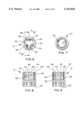
- FIG. 6is a top plan view of the socket.
- FIG. 7is a bottom plan view of the socket.
- FIG. 8is a cross section view taken across the lines 8--8 of FIG. 6.
- FIG. 9is a cross section view taken across the lines 9--9 of FIG. 6.
- FIG. 10is a perspective view of the spring.
- FIG. 11is a top view of the present invention showing the swivel head swivelled to one direction to the greatest extent possible such that the dependent members of the spring are viewed juxtapositioned to the segments in the cavity and showing a lug on the swivel.
- FIG. 12is an enlarged partial cut-away top plan view showing the lug on the sphere engaging the wall of the channel in the socket to drive the socket in a clockwise direction.
- FIG. 13is the view of FIG. 12 showing drive in a counterclockwise direction.
- FIG. 14is a partially cut-away side view showing the swivel head at an angle to the socket and driving the socket by engagement of the driving faces of the lugs with the side walls of the channels.
- FIG. 15is the view of FIG. 14 with the swivel head at a different angle.
- FIG. 16is a cross section of the embodiment in which the segments ate straight-walled.
- FIG. 17is a top plan view of the socket showing clearance channels for the dependent members of the resilient means.
- FIG. 18is a perspective partial view showing the body having a square drive opposite from the cavity.
- FIG. 19is a perspective view of the present invention.
- the impact universal joint 10 of the present inventionhas a socket 12 which receives a swivel head 14.
- a resilient retaining means (flat leaf spring) 16 with dependent members 18is connected to the upper face 20 of the socket 12 (FIGS. 1 and 2).
- the swivel head 14has a substantially spherically portion (sphere) 22.
- a plurality of spaced-apart lugs 24are formed on the sphere 22.
- the lugs 24are formed in a plane around a circumference of the sphere 22.
- the lugsare equispaced.
- Each lug 24has an outer face 26 which is convex curved as will be described.
- Each lug 24further has a pair of opposite driving faces 28 which are convex and in planes parallel to one another. The planes of the driving faces 28 are substantially parallel to the plane of the side wall 48 of the socket 12.
- Axially connected to the sphere 22is a body 30.
- the body 30has a neck portion 32 intermediate between the sphere 22 and a cylindrical portion 34.
- An opening 36is formed in the cylindrical portion 34 distal from the sphere 22.
- the opening 30is square to receive the drive tang of a power driver such as an impact driver (not shown).
- the socket 12has a cavity 38 formed in one end and a connecting means 40 formed in the opposite end.
- the connecting means 40is a hexagonal opening to receive a fastener or other driven workpiece.
- the connecting means 40may have other shapes such as square, spline etc. for specific uses and may be a square drive tang to receive accessories or sockets of varying sizes (FIG. 18).
- the socket 12has an upper face 20 which, preferably, is flat or shaped to retain the resilient retaining means 16.
- the cavity 38has a plurality of spaced-apart channels 42 formed therein dividing the cavity into segments 44. The number of channels 42 corresponds with the number of lugs 24 formed on the sphere 22 in the swivel head 14.
- each channel 42is equispaced so that each of the segments 44 are equal in size.
- each channel 42has a concave curved outer wall 46, the curvature cooperating with the convex curvature of the outer face 26 of the respective lugs 24 on the sphere 22 of the swivel head 24.
- Each channel 42further has parallel substantially-flat side walls 48.
- the segments 44may have a lower portion which is concave. However, the segments 44 may be straight-walled without any curvature (FIG. 16). The sphere 22 of the swivel head 14 is received in the cavity 38.
- the sphere 22cooperates with the segments 44 in the cavity 38; each segment 44 being wider where adjoining the upper face of the sockets and having a lower portion which is concave having a curvature to cooperate with the sphere 22.
- each lug 24 on the sphere 22is disposed in a corresponding channel 42 in the cavity 38 with the outer face 26 of the respective lug 24 cooperating with the respective outer wall 46 of each channel 42.
- the driving faces 28 of each lug 24are opposed to the side walls 48 of the respective channel.
- the convex driving faces 28 of the respective lugs 24allow the sphere 22 to swivel without binding within the segments 44 in the cavity 38 while the driving face 28 maintains sliding contact with the straight side walls of the respective channel 42 and the outer face 26 on the respective lug 24 maintains sliding contact with the outer wall 46 of the respective channel 42 (FIGS. 11-15).
- a resilient retaining means 16such as a flat leaf spring is connected to the socket 12 at the interface between the socket 12 and the swivel head 14.
- the spring 16is mounted on the upper face 20 of the socket.
- the spring 16has a plurality of dependent members 18 formed thereon.
- the dependent members 18are oriented toward the socket 12 and contact the sphere 22 as it is disposed within the cavity 38.
- the dependent members 18are spaced apart and are juxtapositioned to the respective segments 44 in the cavity 38 and between the channels 42. In this manner, the resilient retaining means 16 holds the swivel head 14 securely within the cavity 38 while not restricting the swivelling or angular movement of the swivel head with respect to the socket.
- the dependent members 18, at the end distal from the spring 16,are formed with a return bend 50.
- the return bend 50contacts the sphere 22 on a surface rather than the contact being on an edge. This reduces wear on both the sphere 22 as well as on the member 18 and also facilitates swivel movement of the swivel head 14.
- the spring 16also provides a low level load to hold the swivel head in any selected position. This enables the impact universal joint 10 to effectively and efficiently transmit forces from the power driving tool, through the swivel head and socket, to the workpiece.
- the resilient retaining means 16does not deteriorate with age or use as does a coil spring which is commonly found in impact joints of the prior art.
- clearance channels 52are formed in the segment 44 in the cavity 38 which extend from the upper face 20 of the socket 12' to the bottom of the cavity 38.
- the clearance channelsare opposite from the channels 42.
- the dependent members 18 of the resilient means 16are disposed in the respective clearance channels to provide clearance for the dependent members 18. This reduces the tolerance sensitivity of the dependent members 18 (FIG. 17).
- a further advantage of the impact universal joint of the present inventionis that axial impact forces are transmitted to the driven member because of the configuration of the present invention as described above and because of the spring retaining method. In most prior art, the axial impact forces are not fully utilized. Thus, the present invention is more effective in the removal of "frozen" fasteners where axial impact complements the radial torque.
- the device of the present inventiontransmits force through 360° of rotation of the swivel head about the socket.
Landscapes
- Engineering & Computer Science (AREA)
- General Engineering & Computer Science (AREA)
- Mechanical Engineering (AREA)
- Percussive Tools And Related Accessories (AREA)
Abstract
Description
The present application relates to a universal joint and more particularly, to a universal joint which may be used with power tools to deliver impact to a fastener.
Impact universal joints are used for installing and removing fasteners or other driven workpieces. This is necessary where straight (0° offset) access is difficult or impossible. There are numerous industrial applications. The average citizen most commonly encounters impact universal joints in the automobile garage where the mechanic uses the socket with a power driver to remove and install lug nuts on the wheels of the automobile. The power driver with the impact universal joint provides a means to apply torque to the workpiece and to periodically add an impact to further rotate the workpiece.
Impact universal joints have been known for many years with only a single design dominating the market. This is the "pin and ball" design. In these devices, a ball is received in a torque and impact socket and a pin is disposed in the wall of a socket and through a slot in the ball. The assembly is spring loaded between the ball and the socket interior bottom. The forces on the device are carried, in shear, by the cross-sectional area of the pin. Under the impact and torsinal forces applied, the pin is the most likely member to fail. Increasing the diameter of the pin reduces failure of the pin but causes the slot in the ball to be widened, which decreases the cross-sectional area of the ball which then weakens the ball and becomes a failure point (U.S. Pat. No. 2,441,347 to Dodge).
In U.S. Pat. No. 4,188,801, Hugh et al use a quadrified ball in a square socket. However, in this universal joint, all of the load is carried by the quadrified ball. A force vector analysis shows that the forces are directed to the socket in a manner which applies a significant portion of the forces in a radial direction as opposed to a tangential direction necessary to turn the socket. This applies unwanted radial expansion loads to the sides of the socket and reduces the amount of torque and impact transmitted.
The applicant is also aware of other tools which utilize spherical coaxial members such as U.S. Pat. No. 3,775,997 to Carman, U.S. Pat. No. 5,503,236 to Tibbitts and U.S. Pat. No. 5,573,463 to Arlt. Carman and Tibbitts disclose teeth or lands which are formed on the sphere but are too costly for the consumer tool market.
U.S. Pat. No. 919,651 to Spicer discloses a universal joint which is calculated to withstand heavy pressure due to the transmission of heavy loads with joint members at a considerable angle. The head has spherical curvature. Bearing boxes are arranged to slide in portions of the transverse slot, the sides of said portions serving as guides for the boxes. The bearing boxes are shoes for pivot pin, and, where very light loads are to be transmitted, may not be required with pin sliding and pivoting on guides of a member.
It is an object of the present invention to provide an impact universal joint which efficiently transmits torque to a workpiece while allowing angular misalignment of the swivel head relative to the socket.
It is further an object of the present invention to efficiently transmit torque from lugs on the swivel head to channels within the socket.
It is still another object of the present invention to load the assembly in a secure fashion which does not deteriorate with age and allows the transmission of all axial impact pulses to the socket and/or fastener.
In accordance with the teachings of the present invention, there is disclosed an impact universal joint to transmit force efficiently from a power tool to a workpiece through an angular misalignment, the impact universal joint having a substantially spherically-shaped swivel head. A plurality of spaced-apart lugs are formed in a plane about a circumference of the spherically-shaped swivel head. A body is axially connected to the swivel head. An opening is formed in the body distal from the swivel head. A socket having a cavity formed therein is provided, the cavity receives and cooperates with the swivel head. The cavity has a plurality of spaced-apart channels formed therein dividing the cavity into respective segments. Each channel has a pair of side walls, wherein each respective channel of the cavity receives the respective lug of the swivel head between the side walls thereof. The socket has connecting means formed therein distal from the swivel head. A resilient retaining means is connected to the socket at an interface between the socket and the swivel head. The resilient retaining means retains the swivel head -within the socket and provides a low level load to hold the swivel head in a desired position with respect to the socket. In this manner, driving force applied to the body is transmitted to the socket.
In further accordance with the teaching of the present invention there is disclosed an impact universal joint to transmit force form a tool. The impact universal joint has a substantially spherically-shaped swivel head. A plurality of spaced-apart lugs are formed in a plane about a circumference of the swivel head. A body is axially connected to the swivel head. A connecting means is formed on the body distal from the swivel head for connection to the tool. A socket has a cavity formed therein, the cavity receives and cooperates with the swivel head. Means is provided in the cavity to contact the lugs on the swivel head to transmit force from the swivel head to the socket.
These and other objects of the present invention will become apparent from a reading of the following specification taken in conjunction with the enclosed drawings.
FIG. 1 is a perspective exploded view of the present invention shown from the body of the swivel head toward the cavity of the socket.
FIG. 2 is a perspective exploded view of the present invention shown from the socket toward the swivel head and the body of the swivel head.
FIG. 3 is a side elevation view of the swivel head and the body.
FIG. 4 is a top plan view of the swivel head and the body.
FIG. 5 is a bottom plan view of the swivel head and the body.
FIG. 6 is a top plan view of the socket.
FIG. 7 is a bottom plan view of the socket.
FIG. 8 is a cross section view taken across the lines 8--8 of FIG. 6.
FIG. 9 is a cross section view taken across the lines 9--9 of FIG. 6.
FIG. 10 is a perspective view of the spring.
FIG. 11 is a top view of the present invention showing the swivel head swivelled to one direction to the greatest extent possible such that the dependent members of the spring are viewed juxtapositioned to the segments in the cavity and showing a lug on the swivel.
FIG. 12 is an enlarged partial cut-away top plan view showing the lug on the sphere engaging the wall of the channel in the socket to drive the socket in a clockwise direction.
FIG. 13 is the view of FIG. 12 showing drive in a counterclockwise direction.
FIG. 14 is a partially cut-away side view showing the swivel head at an angle to the socket and driving the socket by engagement of the driving faces of the lugs with the side walls of the channels.
FIG. 15 is the view of FIG. 14 with the swivel head at a different angle.
FIG. 16 is a cross section of the embodiment in which the segments ate straight-walled.
FIG. 17 is a top plan view of the socket showing clearance channels for the dependent members of the resilient means.
FIG. 18 is a perspective partial view showing the body having a square drive opposite from the cavity.
FIG. 19 is a perspective view of the present invention.
The impact universal joint 10 of the present invention has a socket 12 which receives a swivel head 14. A resilient retaining means (flat leaf spring) 16 with dependent members 18 is connected to the upper face 20 of the socket 12 (FIGS. 1 and 2).
As shown in FIGS. 3-5, the swivel head 14 has a substantially spherically portion (sphere) 22. A plurality of spaced-apart lugs 24 are formed on the sphere 22. The lugs 24 are formed in a plane around a circumference of the sphere 22. Preferably, the lugs are equispaced. Each lug 24 has an outer face 26 which is convex curved as will be described. Each lug 24 further has a pair of opposite driving faces 28 which are convex and in planes parallel to one another. The planes of the driving faces 28 are substantially parallel to the plane of the side wall 48 of the socket 12.
Axially connected to the sphere 22 is a body 30. The body 30 has a neck portion 32 intermediate between the sphere 22 and a cylindrical portion 34. An opening 36 is formed in the cylindrical portion 34 distal from the sphere 22. Preferably, the opening 30 is square to receive the drive tang of a power driver such as an impact driver (not shown).
Referring to FIGS. 6-9, the socket 12 has a cavity 38 formed in one end and a connecting means 40 formed in the opposite end. Preferably, the connecting means 40 is a hexagonal opening to receive a fastener or other driven workpiece. The connecting means 40 may have other shapes such as square, spline etc. for specific uses and may be a square drive tang to receive accessories or sockets of varying sizes (FIG. 18). The socket 12 has an upper face 20 which, preferably, is flat or shaped to retain the resilient retaining means 16. The cavity 38 has a plurality of spaced-apart channels 42 formed therein dividing the cavity into segments 44. The number of channels 42 corresponds with the number of lugs 24 formed on the sphere 22 in the swivel head 14. Preferably, the channels 42 are equispaced so that each of the segments 44 are equal in size. Preferably, each channel 42 has a concave curved outer wall 46, the curvature cooperating with the convex curvature of the outer face 26 of the respective lugs 24 on the sphere 22 of the swivel head 24. Each channel 42 further has parallel substantially-flat side walls 48. The segments 44 may have a lower portion which is concave. However, the segments 44 may be straight-walled without any curvature (FIG. 16). The sphere 22 of the swivel head 14 is received in the cavity 38. In the embodiment with curved segments 44, the sphere 22 cooperates with the segments 44 in the cavity 38; each segment 44 being wider where adjoining the upper face of the sockets and having a lower portion which is concave having a curvature to cooperate with the sphere 22.
The sphere 22 is received in the cavity 38 such that each lug 24 on the sphere 22 is disposed in a corresponding channel 42 in the cavity 38 with the outer face 26 of the respective lug 24 cooperating with the respective outer wall 46 of each channel 42. The driving faces 28 of each lug 24 are opposed to the side walls 48 of the respective channel. The convex driving faces 28 of the respective lugs 24 allow the sphere 22 to swivel without binding within the segments 44 in the cavity 38 while the driving face 28 maintains sliding contact with the straight side walls of the respective channel 42 and the outer face 26 on the respective lug 24 maintains sliding contact with the outer wall 46 of the respective channel 42 (FIGS. 11-15). Due to the configuration of the faces of the lugs 24 and the configuration of the walls of the channels 42, force applied to the body 30 of the swivel head 14 is transmitted to the socket. The transmission of force is very efficient because the driving faces 28 on the lugs 24 are able to transmit forces perpendicularly to the side walls 48 of the channel 42 irrespective of the angle between the swivel head 14 and the socket 12.
A resilient retaining means 16, such as a flat leaf spring is connected to the socket 12 at the interface between the socket 12 and the swivel head 14. Preferably, the spring 16 is mounted on the upper face 20 of the socket. The spring 16 has a plurality of dependent members 18 formed thereon. The dependent members 18 are oriented toward the socket 12 and contact the sphere 22 as it is disposed within the cavity 38. The dependent members 18 are spaced apart and are juxtapositioned to the respective segments 44 in the cavity 38 and between the channels 42. In this manner, the resilient retaining means 16 holds the swivel head 14 securely within the cavity 38 while not restricting the swivelling or angular movement of the swivel head with respect to the socket. The dependent members 18, at the end distal from the spring 16, are formed with a return bend 50. The return bend 50 contacts the sphere 22 on a surface rather than the contact being on an edge. This reduces wear on both the sphere 22 as well as on the member 18 and also facilitates swivel movement of the swivel head 14. The spring 16 also provides a low level load to hold the swivel head in any selected position. This enables the impact universal joint 10 to effectively and efficiently transmit forces from the power driving tool, through the swivel head and socket, to the workpiece. The resilient retaining means 16 does not deteriorate with age or use as does a coil spring which is commonly found in impact joints of the prior art.
It is also preferred, for manufacturing purposes, to form clearance channels 52 in the segment 44 in the cavity 38 which extend from the upper face 20 of the socket 12' to the bottom of the cavity 38. The clearance channels are opposite from the channels 42. The dependent members 18 of the resilient means 16 are disposed in the respective clearance channels to provide clearance for the dependent members 18. This reduces the tolerance sensitivity of the dependent members 18 (FIG. 17).
A further advantage of the impact universal joint of the present invention is that axial impact forces are transmitted to the driven member because of the configuration of the present invention as described above and because of the spring retaining method. In most prior art, the axial impact forces are not fully utilized. Thus, the present invention is more effective in the removal of "frozen" fasteners where axial impact complements the radial torque. The device of the present invention transmits force through 360° of rotation of the swivel head about the socket.
Obviously, many modifications may be made without departing from the basic spirit of the present invention. Accordingly, it will be appreciated by those skilled in the art that within the scope of the appended claims, the invention may be practiced other than has been specifically described herein.
Claims (12)
1. An impact universal joint to transmits force efficiently from a power tool to a workpiece through an angular misalignment, the impact universal joint comprising a non-truncated spherical swivel head,
three equally spaced-apart lugs extending outwardly from the spherical swivel head and formed in an equatorial plane about a circumference of the spherical swivel head, each lug having a pair of opposite convex driving faces,
a body axially connected to the swivel head,
an opening formed in the body distal from the swivel head,
a socket having a cavity formed therein, the cavity receiving and cooperating with the swivel head,
the cavity having a plurality of spaced-apart channels formed therein dividing the cavity into respective segments, each channel having a pair of side walls, wherein the side walls of each respective channel of the cavity receive the respective lug of the swivel head between the side walls thereof,
the socket having connecting means formed therein distal from the swivel head,
an axially resilient retaining means connected to the socket at an interface between the socket and the swivel head, the resilient retaining means retaining the swivel head within the socket and providing a low level load to hold the swivel head in a desired position with respect to the socket,
wherein driving force applied to the body is transmitted axially and radially to the socket.
2. The joint of claim 1, wherein the connecting means on the socket is an opening to receive and cooperate with a fastener.
3. The joint of claim 1, wherein the connecting means on the socket is a male drive to receive an accessory.
4. The joint of claim 1, wherein each lug has a respective outer face curved to cooperate with an outer wall of the respective channel, wherein the spherical swivel head swivels within the socket without binding, wherein the driving forces being applied to the body are transmitted to the driving faces on the swivel head such that the driving faces of the respective lugs direct the force perpendicularly onto the side walls of the respective channels within the socket to produce rotation of the socket.
5. The joint of claim 1, wherein the plane of the plurality of lugs is substantially perpendicular to a center line through the body and swivel head.
6. The joint of claim 1, wherein each segment is concave and cooperating with the spherical swivel head.
7. An impact universal joint to transmit force efficiently from a power tool to a workpiece through an angular misalignment the impact universal joint comprising a substantially spherically-shaped swivel head,
a plurality of spaced-apart lugs formed in a plane about a circumference of the spherically-shaped swivel head,
a body axially connected to the swivel head,
an opening formed in the body distal from the swivel head,
a socket having a cavity formed therein, the cavity receiving and cooperating with the swivel head,
the cavity having a plurality of spaced-apart channels formed therein dividing the cavity into respective segments, each channel having a pair of side walls, wherein each respective channel of the cavity receives the respective lug of the swivel head between the side walls thereof,
the socket having connecting means formed therein distal from the swivel head,
a resilient retaining means connected to the socket at an interface between the socket and the swivel head, the resilient retaining means retaining the swivel head within the socket and providing a low level load to hold the swivel head in a desired position with respect to the socket,
wherein driving force applied to the body is transmitted to the socket,
wherein the resilient retaining means is a leaf spring having a plurality of dependent members formed thereon, wherein the dependent members contact the spherical swivel head and are juxtapositioned to the respective segments of the cavity between the channels in the cavity.
8. An impact universal joint to transmit force from a tool comprising:
a non-truncated spherical swivel head,
three equally spaced-apart lugs extending outwardly from the spherical swivel head and formed in an equatorial plane about a circumference of the swivel head,
a body axially connected to the swivel head,
a connecting means formed on the body distal from the swivel head for connection to the tool,
a socket having a cavity formed therein, the cavity receiving and cooperating with the swivel head, wherein axial force is transmitted from the non-truncated spherical swivel head to the socket, and
means in the cavity to contact the lugs on the swivel head to transmit radial force from the swivel head to the socket.
9. The joint of claim 8, further comprising an axially resilient retaining means being connected to an interface between the swivel head and the socket.
10. The joint of claim 8, wherein the means in the cavity to contact the lugs on the swivel head are a plurality of spaced-apart channels formed in the cavity, each channel having a pair of side walls, wherein each respective channel receives a respective lug between the side walls and application of force to the swivel head is transmitted through the lugs to the side walls of the channels and to the socket.
11. An impact universal joint to transmit force from a tool comprising:
a non-truncated spherical swivel head,
a plurality of spaced-apart lugs formed in a plane about a circumference of the swivel head,
a body axially connected to the swivel head,
a connecting means formed on the body distal from the swivel head for connection to the tool,
a socket having a cavity formed therein, the cavity receiving and cooperating with the swivel head,
means in the cavity to contact the lugs on the swivel head to transmit force from the swivel head to the socket,
an axially resilient retaining means being connected to an interface between the swivel head and the socket, and
the resilient retaining means having a plurality of dependent members formed thereon, the dependent members contacting the spherical swivel head.
12. An impact universal joint to transmit force from a tool comprising:
a substantially spherically-shaped swivel head,
a plurality of spaced-apart lugs formed in a plane about a circumference of the swivel head,
a body axially connected to the swivel head,
a connecting means formed on the body distal from the swivel head for connection to the tool,
a socket having a cavity formed therein, the cavity receiving and cooperating with the swivel head,
means in the cavity to contact the lugs on the swivel head to transmit force from the swivel head to the socket,
a resilient retaining means being connected to an interface between the swivel head and the socket,
the resilient retaining means having a plurality of dependent members formed thereon, the dependent members contacting the spherical swivel head, and
further comprising a plurality of clearance channels formed in the cavity, wherein the plurality of dependent members are each disposed in a respective clearance channel.
Priority Applications (1)
| Application Number | Priority Date | Filing Date | Title |
|---|---|---|---|
| US09/069,461US6152826A (en) | 1998-04-29 | 1998-04-29 | Impact universal joint |
Applications Claiming Priority (1)
| Application Number | Priority Date | Filing Date | Title |
|---|---|---|---|
| US09/069,461US6152826A (en) | 1998-04-29 | 1998-04-29 | Impact universal joint |
Publications (1)
| Publication Number | Publication Date |
|---|---|
| US6152826Atrue US6152826A (en) | 2000-11-28 |
Family
ID=22089123
Family Applications (1)
| Application Number | Title | Priority Date | Filing Date |
|---|---|---|---|
| US09/069,461Expired - Fee RelatedUS6152826A (en) | 1998-04-29 | 1998-04-29 | Impact universal joint |
Country Status (1)
| Country | Link |
|---|---|
| US (1) | US6152826A (en) |
Cited By (61)
| Publication number | Priority date | Publication date | Assignee | Title |
|---|---|---|---|---|
| USD445120S1 (en) | 2000-07-10 | 2001-07-17 | James K Parsons | Channeled guide ball universal joint |
| US6431031B1 (en) | 1999-12-16 | 2002-08-13 | Bobby Hu | Reversible ratcheting tool with a smaller head |
| US6450066B1 (en) | 2001-10-19 | 2002-09-17 | Bobby Hu | Head of a wrench handle |
| US6453779B2 (en) | 2000-07-21 | 2002-09-24 | Bobby Hu | Positioning device for a switch member of a reversible ratchet-type wrench |
| US6457387B1 (en) | 2000-01-11 | 2002-10-01 | Bobby Hu | Reversible ratcheting tool with a smaller head and improved driving torque |
| US6457389B1 (en) | 2000-08-22 | 2002-10-01 | Bobby Hu | Switching arrangement for a reversible ratchet type wrench |
| US6520051B1 (en) | 2001-12-27 | 2003-02-18 | Bobby Hu | Head of a wrench handle |
| US6539825B1 (en) | 2001-09-20 | 2003-04-01 | Yen-Wen Lin | Single direction ratcheting wrench with stuck prevention and ratcheting direction indication |
| US6568299B2 (en) | 1999-12-16 | 2003-05-27 | Bobby Hu | Reversible ratcheting tool with a smaller head |
| US6575062B2 (en)* | 2000-05-24 | 2003-06-10 | Wiha Werkzeuge, Willi Hahn Gmbh & Co. Kg | Accommodating head for a tool with an actuating tip |
| US6644148B2 (en) | 2002-02-08 | 2003-11-11 | Bobby Hu | Reversible ratchet-type wrench |
| US6647832B2 (en) | 2001-07-27 | 2003-11-18 | Bobby Hu | Wrench having two rigid supporting areas for a pawl |
| US6666117B2 (en) | 2001-07-13 | 2003-12-23 | Bobby Hu | Wrench with a fixed maximum operational torque |
| US6666112B2 (en) | 2000-09-01 | 2003-12-23 | Bobby Hu | Switching arrangement for a reversible ratchet type wrench |
| USD484376S1 (en) | 2002-06-18 | 2003-12-30 | Hand Tool Design Corporation | Laser etched socket |
| US6722234B2 (en) | 2001-05-14 | 2004-04-20 | Bobby Hu | Easy-to-operate and easy-to-assemble ratcheting-type wrench |
| US6732614B2 (en) | 2001-02-19 | 2004-05-11 | Bobby Hu | Easy-to-manufacture and easy-to-assemble ratcheting-type wrench |
| US6745647B2 (en) | 2000-11-29 | 2004-06-08 | Mei-Chen Wang | Wrench having a universal-joint ratchet wheel |
| US20040120755A1 (en)* | 2002-12-18 | 2004-06-24 | Butler George H. | Multi-axis coupler |
| US20040121845A1 (en)* | 2002-12-19 | 2004-06-24 | Hand Tool Design Corporation | Universal joint |
| US6758641B2 (en) | 2001-07-13 | 2004-07-06 | Bobby Hu | Method for manufacturing a ratchet type ring spanner having a larger cavity for receiving a larger pawl |
| US6807882B2 (en) | 2001-05-07 | 2004-10-26 | Bobby Hu | Wrench with a simplified structure |
| USD500435S1 (en) | 2003-02-07 | 2005-01-04 | Easco Hand Tools, Inc. | Laser etched socket |
| USD500944S1 (en) | 2003-02-07 | 2005-01-18 | Easco Hand Tools, Inc. | Laser etched socket |
| USD501768S1 (en) | 2003-02-07 | 2005-02-15 | Easco Hand Tools, Inc. | Laser etched socket |
| US20050119056A1 (en)* | 2003-12-01 | 2005-06-02 | Chien Shih L. | Universal connector structure |
| US20050119057A1 (en)* | 2003-11-27 | 2005-06-02 | Nissan Rom | Joint for the transmission of rotational motion |
| US20050171546A1 (en)* | 1999-11-15 | 2005-08-04 | Wolf Eugene M. | Tapered bioabsorbable interference screw for endosteal fixation of ligaments |
| US6945141B2 (en) | 2002-04-22 | 2005-09-20 | Bobby Hu | Reversible ratchet type wrench |
| US6955104B2 (en) | 2000-03-13 | 2005-10-18 | Bobby Hu | Reversible ratcheting tool with a smaller head |
| US6971286B2 (en) | 2002-07-22 | 2005-12-06 | Bobby Hu | Ratcheting wrench with quick tightening/loosening functions and fine adjusting functions |
| US20060000306A1 (en)* | 2004-06-16 | 2006-01-05 | Gerold Schmitt | Device for positioning a component part in an inclined position and impact test stand having such a device |
| US7017453B2 (en) | 2001-10-17 | 2006-03-28 | Bobby Hu | Reversible ratchet-type wrench |
| US7178429B2 (en) | 2002-08-05 | 2007-02-20 | Yen-Wen Lin | Easy-to-assemble ratcheting tool |
| US20070082745A1 (en)* | 2005-10-11 | 2007-04-12 | Norris Todd A | Retainer for a constant velocity universal joint assembly |
| US7237460B2 (en) | 2000-02-03 | 2007-07-03 | Bobby Hu | Biasing arrangement for a pawl of a reversible ratchet-type wrench |
| US20070234854A1 (en)* | 2005-11-13 | 2007-10-11 | Ronny Collins | Bendable-head power ratchet tool |
| US20080012245A1 (en)* | 2006-07-12 | 2008-01-17 | Black & Decker Inc. | Pivotal/Rigid Accessories for Power And Hand Tools |
| USD589319S1 (en) | 2007-02-08 | 2009-03-31 | Black & Decker Inc. | Pivoting bit holder |
| GB2466210A (en)* | 2008-12-11 | 2010-06-16 | Agco Gmbh & Co | Torque wrench attachment with constant velocity joint |
| KR101046535B1 (en) | 2011-03-28 | 2011-07-05 | 주식회사 형근 | Rotary Motion Processing Equipment |
| US20110197719A1 (en)* | 2010-02-16 | 2011-08-18 | Neitzell Roger D | Driver accessory |
| USD649417S1 (en) | 2010-05-21 | 2011-11-29 | Ian Lyle Gresham | Socket |
| USRE43286E1 (en) | 1999-08-03 | 2012-04-03 | Bobby Hu | Ratchet wheel with asymmetric arcuate concave teeth or non-arcuate concave teeth ratcheting tools with such ratchet wheel and combination of such ratchet wheel and a pawl |
| US8246476B2 (en) | 2010-04-19 | 2012-08-21 | Yuan Li Hsing Industrial Co., Ltd. | Universal joint |
| USD666466S1 (en) | 2010-05-21 | 2012-09-04 | Apex Brands, Inc. | Ratchet wrench |
| US8292150B2 (en) | 2010-11-02 | 2012-10-23 | Tyco Healthcare Group Lp | Adapter for powered surgical devices |
| US20150005080A1 (en)* | 2013-06-30 | 2015-01-01 | Hung-Pin Chu | Universal joint structure for a tool |
| US20150165605A1 (en)* | 2013-12-18 | 2015-06-18 | Shwu-Ruu Chern | Universal connector unit |
| US9176468B2 (en) | 2006-12-22 | 2015-11-03 | Canon Kabushiki Kaisha | Rotational force transmitting part |
| US20160138646A1 (en)* | 2014-11-14 | 2016-05-19 | Hella Kgaa Hueck & Co. | Ball Joint Connection |
| US9477201B2 (en) | 2008-06-20 | 2016-10-25 | Canon Kabushiki Kaisha | Cartridge, mounting method for coupling member, and disassembling method for coupling member |
| US9678471B2 (en) | 2006-12-22 | 2017-06-13 | Canon Kabushiki Kaisha | Process cartridge, electrophotographic image forming apparatus, and electrophotographic photosensitive drum unit |
| US9703257B2 (en) | 2007-03-23 | 2017-07-11 | Canon Kabushiki Kaisha | Electrophotographic image forming apparatus, developing apparatus, and coupling member |
| DE102016221088A1 (en)* | 2016-10-26 | 2018-04-26 | Bayerische Motoren Werke Aktiengesellschaft | Angle compensation device for a tool |
| US10323470B2 (en) | 2014-12-30 | 2019-06-18 | Halliburton Energy Services, Inc. | Constant velocity joint apparatus, systems, and methods |
| TWI669455B (en)* | 2018-02-12 | 2019-08-21 | 蔡志昇 | Universal sleeve |
| US11041523B2 (en)* | 2019-07-16 | 2021-06-22 | Fine Forge Industry Corporation | Universal joint |
| GB2593869A (en)* | 2020-03-24 | 2021-10-13 | Atlas Copco Ind Technique Ab | Nut rotating socket and a base for a hydraulic tensioner |
| US11331106B2 (en) | 2012-07-12 | 2022-05-17 | DePuy Synthes Products, Inc. | Torque transmitting ball joint driver having a rigid fixation mechanism |
| US11346402B2 (en)* | 2019-02-01 | 2022-05-31 | Jhih Sheng Tsai | Universal socket structure |
Citations (25)
| Publication number | Priority date | Publication date | Assignee | Title |
|---|---|---|---|---|
| US76819A (en)* | 1868-04-14 | Improvement in shaft-coupling | ||
| US797820A (en)* | 1904-11-28 | 1905-08-22 | Cox And Prentiss | Tool-holder. |
| US919651A (en)* | 1907-09-10 | 1909-04-27 | Clarence W Spicer | Universal joint. |
| US1335913A (en)* | 1920-04-06 | Universal joimt | ||
| US1868891A (en)* | 1928-10-09 | 1932-07-26 | Faudi Fritz | Coupling |
| US2136947A (en)* | 1936-03-26 | 1938-11-15 | Morgan Construction Co | Coupling |
| FR914232A (en)* | 1945-04-05 | 1946-10-02 | Air Equipement | Improvements to drive devices using ball joint shafts, in particular for driving accessories on board aerodynes |
| US2441347A (en)* | 1940-05-11 | 1948-05-11 | Borg Warner | Universal joint |
| US2760358A (en)* | 1954-03-15 | 1956-08-28 | Tony W Helm | Universal joint |
| US2854829A (en)* | 1957-07-15 | 1958-10-07 | Warren E Swarthout | Universal joint |
| US2976702A (en)* | 1959-03-18 | 1961-03-28 | Union Tank Car Co | Rolling mill power transmission locking arrangement |
| US3054275A (en)* | 1960-06-24 | 1962-09-18 | Int Research & Dev Co Ltd | Universal drive shaft coupling |
| US3775997A (en)* | 1972-05-18 | 1973-12-04 | Koppers Co Inc | Gear type coupling |
| US3826108A (en)* | 1973-08-03 | 1974-07-30 | L Watkins | Rolling mill drive construction |
| US4141225A (en)* | 1977-02-10 | 1979-02-27 | The United States Of America As Represented By The Secretary Of The Interior | Articulated, flexible shaft assembly with axially lockable universal joint |
| US4188801A (en)* | 1978-07-03 | 1980-02-19 | Ingersoll-Rand Company | Universal joint |
| US4370869A (en)* | 1979-07-18 | 1983-02-01 | Jonassen Jorgen W | Gear-type universal coupling |
| US4482266A (en)* | 1981-10-23 | 1984-11-13 | Tokico Ltd. | Ball joint |
| US5007880A (en)* | 1990-05-09 | 1991-04-16 | Walker Stanley L | Bevel splined articulated joint |
| US5152628A (en)* | 1990-10-13 | 1992-10-06 | Trw Ehrenreich Gmbh & Co. Kg | Ball-and-socket joint |
| US5503236A (en)* | 1993-09-03 | 1996-04-02 | Baker Hughes Incorporated | Swivel/tilting bit crown for earth-boring drills |
| US5527220A (en)* | 1994-03-23 | 1996-06-18 | Halliburton Company | Articulatable joint with multi-faceted ball and socket |
| US5573463A (en)* | 1994-05-20 | 1996-11-12 | Continental Emsco Company | Elastomeric drive line coupling for transmitting torque and simultaneously accomodating shaft misalignments and angular deflections |
| US5782574A (en)* | 1993-11-15 | 1998-07-21 | Trw Fahrwerkesystems Gmbh & Co. | Ball and socket joint |
| US5851151A (en)* | 1995-03-23 | 1998-12-22 | Stanley Mechanics Tools | Pinless impact universal joint |
- 1998
- 1998-04-29USUS09/069,461patent/US6152826A/ennot_activeExpired - Fee Related
Patent Citations (25)
| Publication number | Priority date | Publication date | Assignee | Title |
|---|---|---|---|---|
| US76819A (en)* | 1868-04-14 | Improvement in shaft-coupling | ||
| US1335913A (en)* | 1920-04-06 | Universal joimt | ||
| US797820A (en)* | 1904-11-28 | 1905-08-22 | Cox And Prentiss | Tool-holder. |
| US919651A (en)* | 1907-09-10 | 1909-04-27 | Clarence W Spicer | Universal joint. |
| US1868891A (en)* | 1928-10-09 | 1932-07-26 | Faudi Fritz | Coupling |
| US2136947A (en)* | 1936-03-26 | 1938-11-15 | Morgan Construction Co | Coupling |
| US2441347A (en)* | 1940-05-11 | 1948-05-11 | Borg Warner | Universal joint |
| FR914232A (en)* | 1945-04-05 | 1946-10-02 | Air Equipement | Improvements to drive devices using ball joint shafts, in particular for driving accessories on board aerodynes |
| US2760358A (en)* | 1954-03-15 | 1956-08-28 | Tony W Helm | Universal joint |
| US2854829A (en)* | 1957-07-15 | 1958-10-07 | Warren E Swarthout | Universal joint |
| US2976702A (en)* | 1959-03-18 | 1961-03-28 | Union Tank Car Co | Rolling mill power transmission locking arrangement |
| US3054275A (en)* | 1960-06-24 | 1962-09-18 | Int Research & Dev Co Ltd | Universal drive shaft coupling |
| US3775997A (en)* | 1972-05-18 | 1973-12-04 | Koppers Co Inc | Gear type coupling |
| US3826108A (en)* | 1973-08-03 | 1974-07-30 | L Watkins | Rolling mill drive construction |
| US4141225A (en)* | 1977-02-10 | 1979-02-27 | The United States Of America As Represented By The Secretary Of The Interior | Articulated, flexible shaft assembly with axially lockable universal joint |
| US4188801A (en)* | 1978-07-03 | 1980-02-19 | Ingersoll-Rand Company | Universal joint |
| US4370869A (en)* | 1979-07-18 | 1983-02-01 | Jonassen Jorgen W | Gear-type universal coupling |
| US4482266A (en)* | 1981-10-23 | 1984-11-13 | Tokico Ltd. | Ball joint |
| US5007880A (en)* | 1990-05-09 | 1991-04-16 | Walker Stanley L | Bevel splined articulated joint |
| US5152628A (en)* | 1990-10-13 | 1992-10-06 | Trw Ehrenreich Gmbh & Co. Kg | Ball-and-socket joint |
| US5503236A (en)* | 1993-09-03 | 1996-04-02 | Baker Hughes Incorporated | Swivel/tilting bit crown for earth-boring drills |
| US5782574A (en)* | 1993-11-15 | 1998-07-21 | Trw Fahrwerkesystems Gmbh & Co. | Ball and socket joint |
| US5527220A (en)* | 1994-03-23 | 1996-06-18 | Halliburton Company | Articulatable joint with multi-faceted ball and socket |
| US5573463A (en)* | 1994-05-20 | 1996-11-12 | Continental Emsco Company | Elastomeric drive line coupling for transmitting torque and simultaneously accomodating shaft misalignments and angular deflections |
| US5851151A (en)* | 1995-03-23 | 1998-12-22 | Stanley Mechanics Tools | Pinless impact universal joint |
Cited By (136)
| Publication number | Priority date | Publication date | Assignee | Title |
|---|---|---|---|---|
| USRE43286E1 (en) | 1999-08-03 | 2012-04-03 | Bobby Hu | Ratchet wheel with asymmetric arcuate concave teeth or non-arcuate concave teeth ratcheting tools with such ratchet wheel and combination of such ratchet wheel and a pawl |
| US20050171546A1 (en)* | 1999-11-15 | 2005-08-04 | Wolf Eugene M. | Tapered bioabsorbable interference screw for endosteal fixation of ligaments |
| US7322986B2 (en)* | 1999-11-15 | 2008-01-29 | Arthrex, Inc. | Bioabsorbable interference screw for endosteal fixation of ligaments |
| US20080058819A1 (en)* | 1999-11-15 | 2008-03-06 | Wolf Eugene M | Bioabsorbable interference screw for endosteal fixation of ligaments |
| US6431031B1 (en) | 1999-12-16 | 2002-08-13 | Bobby Hu | Reversible ratcheting tool with a smaller head |
| US6568299B2 (en) | 1999-12-16 | 2003-05-27 | Bobby Hu | Reversible ratcheting tool with a smaller head |
| US7234372B2 (en) | 2000-01-11 | 2007-06-26 | Bobby Hu | Reversible ratcheting tool with a smaller head and improved driving torque |
| US6457387B1 (en) | 2000-01-11 | 2002-10-01 | Bobby Hu | Reversible ratcheting tool with a smaller head and improved driving torque |
| US7237460B2 (en) | 2000-02-03 | 2007-07-03 | Bobby Hu | Biasing arrangement for a pawl of a reversible ratchet-type wrench |
| US6955104B2 (en) | 2000-03-13 | 2005-10-18 | Bobby Hu | Reversible ratcheting tool with a smaller head |
| US6575062B2 (en)* | 2000-05-24 | 2003-06-10 | Wiha Werkzeuge, Willi Hahn Gmbh & Co. Kg | Accommodating head for a tool with an actuating tip |
| USD445120S1 (en) | 2000-07-10 | 2001-07-17 | James K Parsons | Channeled guide ball universal joint |
| US6453779B2 (en) | 2000-07-21 | 2002-09-24 | Bobby Hu | Positioning device for a switch member of a reversible ratchet-type wrench |
| US6457389B1 (en) | 2000-08-22 | 2002-10-01 | Bobby Hu | Switching arrangement for a reversible ratchet type wrench |
| US6666112B2 (en) | 2000-09-01 | 2003-12-23 | Bobby Hu | Switching arrangement for a reversible ratchet type wrench |
| US6745647B2 (en) | 2000-11-29 | 2004-06-08 | Mei-Chen Wang | Wrench having a universal-joint ratchet wheel |
| US6732614B2 (en) | 2001-02-19 | 2004-05-11 | Bobby Hu | Easy-to-manufacture and easy-to-assemble ratcheting-type wrench |
| US6807882B2 (en) | 2001-05-07 | 2004-10-26 | Bobby Hu | Wrench with a simplified structure |
| US6722234B2 (en) | 2001-05-14 | 2004-04-20 | Bobby Hu | Easy-to-operate and easy-to-assemble ratcheting-type wrench |
| US6758641B2 (en) | 2001-07-13 | 2004-07-06 | Bobby Hu | Method for manufacturing a ratchet type ring spanner having a larger cavity for receiving a larger pawl |
| US6666117B2 (en) | 2001-07-13 | 2003-12-23 | Bobby Hu | Wrench with a fixed maximum operational torque |
| US6647832B2 (en) | 2001-07-27 | 2003-11-18 | Bobby Hu | Wrench having two rigid supporting areas for a pawl |
| US6539825B1 (en) | 2001-09-20 | 2003-04-01 | Yen-Wen Lin | Single direction ratcheting wrench with stuck prevention and ratcheting direction indication |
| US7017453B2 (en) | 2001-10-17 | 2006-03-28 | Bobby Hu | Reversible ratchet-type wrench |
| US6450066B1 (en) | 2001-10-19 | 2002-09-17 | Bobby Hu | Head of a wrench handle |
| US6520051B1 (en) | 2001-12-27 | 2003-02-18 | Bobby Hu | Head of a wrench handle |
| US6644148B2 (en) | 2002-02-08 | 2003-11-11 | Bobby Hu | Reversible ratchet-type wrench |
| US6945141B2 (en) | 2002-04-22 | 2005-09-20 | Bobby Hu | Reversible ratchet type wrench |
| USD484376S1 (en) | 2002-06-18 | 2003-12-30 | Hand Tool Design Corporation | Laser etched socket |
| US6971286B2 (en) | 2002-07-22 | 2005-12-06 | Bobby Hu | Ratcheting wrench with quick tightening/loosening functions and fine adjusting functions |
| US7032478B2 (en) | 2002-07-22 | 2006-04-25 | Bobby Hu | Ratcheting wrench with quick tightening/loosening functions and fine adjusting functions |
| US7178429B2 (en) | 2002-08-05 | 2007-02-20 | Yen-Wen Lin | Easy-to-assemble ratcheting tool |
| US20040120755A1 (en)* | 2002-12-18 | 2004-06-24 | Butler George H. | Multi-axis coupler |
| US6869366B2 (en) | 2002-12-19 | 2005-03-22 | Easco Hand Tools Inc. | Universal joint |
| US20040121845A1 (en)* | 2002-12-19 | 2004-06-24 | Hand Tool Design Corporation | Universal joint |
| US20050143179A1 (en)* | 2002-12-19 | 2005-06-30 | Easco Hand Tools, Inc. | Universal joint |
| US7153214B2 (en) | 2002-12-19 | 2006-12-26 | Easco Hand Tools, Inc. | Universal joint |
| USD501768S1 (en) | 2003-02-07 | 2005-02-15 | Easco Hand Tools, Inc. | Laser etched socket |
| USD523305S1 (en) | 2003-02-07 | 2006-06-20 | Easco Hand Tools, Inc. | Laser etched socket |
| USRE43408E1 (en) | 2003-02-07 | 2012-05-29 | Apex Brands, Inc. | Laser etched socket |
| USD500944S1 (en) | 2003-02-07 | 2005-01-18 | Easco Hand Tools, Inc. | Laser etched socket |
| USD500435S1 (en) | 2003-02-07 | 2005-01-04 | Easco Hand Tools, Inc. | Laser etched socket |
| USRE42400E1 (en) | 2003-02-07 | 2011-05-31 | Easco Hand Tools, Inc. | Laser etched socket |
| US20050119057A1 (en)* | 2003-11-27 | 2005-06-02 | Nissan Rom | Joint for the transmission of rotational motion |
| US7854659B2 (en)* | 2003-11-27 | 2010-12-21 | Mag-Eh, Ltd. | Joint for the transmission of rotational motion |
| US20050119056A1 (en)* | 2003-12-01 | 2005-06-02 | Chien Shih L. | Universal connector structure |
| US20060000306A1 (en)* | 2004-06-16 | 2006-01-05 | Gerold Schmitt | Device for positioning a component part in an inclined position and impact test stand having such a device |
| US7380434B2 (en)* | 2004-06-16 | 2008-06-03 | Robert Bosch Gmbh | Device for positioning a component part in an inclined position and impact test stand having such a device |
| US20070082745A1 (en)* | 2005-10-11 | 2007-04-12 | Norris Todd A | Retainer for a constant velocity universal joint assembly |
| US20070234854A1 (en)* | 2005-11-13 | 2007-10-11 | Ronny Collins | Bendable-head power ratchet tool |
| EP1878524A3 (en)* | 2006-07-12 | 2012-05-16 | Black & Decker, Inc. | Pivotal/rigid accessories for power and hand tools |
| US7942426B2 (en) | 2006-07-12 | 2011-05-17 | Black & Decker Inc. | Pivotal/rigid accessories for power and hand tools |
| US20080012245A1 (en)* | 2006-07-12 | 2008-01-17 | Black & Decker Inc. | Pivotal/Rigid Accessories for Power And Hand Tools |
| US9176468B2 (en) | 2006-12-22 | 2015-11-03 | Canon Kabushiki Kaisha | Rotational force transmitting part |
| US9874854B2 (en) | 2006-12-22 | 2018-01-23 | Canon Kabushiki Kaisha | Process cartridge, electrophotographic image forming apparatus, and electrophotographic photosensitive drum unit |
| US9841728B2 (en) | 2006-12-22 | 2017-12-12 | Canon Kabushiki Kaisha | Process cartridge having changeable relative positioning of a coupling member and another part of the process cartridge |
| US10671018B2 (en) | 2006-12-22 | 2020-06-02 | Canon Kabushiki Kaisha | Process cartridge, electrophotographic image forming apparatus, and electrophotographic photosensitive drum unit |
| US12405567B2 (en) | 2006-12-22 | 2025-09-02 | Canon Kabushiki Kaisha | Process cartridge, electrophotographic image forming apparatus, and electrophotographic photosensitive drum unit |
| US10551793B2 (en) | 2006-12-22 | 2020-02-04 | Canon Kabushiki Kaisha | Process cartridge, electrophotographic image forming apparatus, and electrophotographic photosensitive drum unit |
| US10539923B2 (en) | 2006-12-22 | 2020-01-21 | Canon Kabushiki Kaisha | Process cartridge, electrophotographic image forming apparatus, and electrophotographic photosensitive drum unit |
| US10539924B2 (en) | 2006-12-22 | 2020-01-21 | Canon Kabushiki Kaisha | Process cartridge, electrophotographic image forming apparatus, and electrophotographic photosensitive drum unit |
| US10429794B2 (en) | 2006-12-22 | 2019-10-01 | Canon Kabushiki Kaisha | Rotational force transmitting part |
| US10877433B2 (en) | 2006-12-22 | 2020-12-29 | Canon Kabushiki Kaisha | Process cartridge, electrophotographic image forming apparatus, and electrophotographic photosensitive drum unit |
| US11720054B2 (en) | 2006-12-22 | 2023-08-08 | Canon Kabushiki Kaisha | Process cartridge, electrophotographic image forming apparatus, and electrophotographic photosensitive drum unit |
| US10209670B2 (en) | 2006-12-22 | 2019-02-19 | Canon Kabushiki Kaisha | Rotational force transmitting part |
| US11237517B2 (en) | 2006-12-22 | 2022-02-01 | Canon Kabushiki Kaisha | Process cartridge, electrophotographic image forming apparatus, and electrophotographic photosensitive drum unit |
| US10845756B2 (en) | 2006-12-22 | 2020-11-24 | Canon Kabushiki Kaisha | Rotational force transmitting part |
| US10585391B2 (en) | 2006-12-22 | 2020-03-10 | Canon Kabushiki Kaisha | Process cartridge, electrophotographic image forming apparatus, and electrophotographic photosensitive drum unit |
| US9846408B2 (en) | 2006-12-22 | 2017-12-19 | Canon Kabushiki Kaisha | Process cartridge, electrophotographic image forming apparatus, and electrophotographic photosensitive drum unit |
| US9869960B2 (en) | 2006-12-22 | 2018-01-16 | Canon Kabushiki Kaisha | Process cartridge, electrophotographic image forming apparatus, and electrophotographic photosensitive drum unit |
| US9874846B2 (en) | 2006-12-22 | 2018-01-23 | Canon Kabushiki Kaisha | Process cartridge, electrophotographic image forming apparatus, and electrophotographic photosensitive drum unit |
| US11156956B2 (en) | 2006-12-22 | 2021-10-26 | Canon Kabushiki Kaisha | Rotational force transmitting part |
| US9678471B2 (en) | 2006-12-22 | 2017-06-13 | Canon Kabushiki Kaisha | Process cartridge, electrophotographic image forming apparatus, and electrophotographic photosensitive drum unit |
| US9864333B2 (en) | 2006-12-22 | 2018-01-09 | Canon Kabushiki Kaisha | Process cartridge, electrophotographic image forming apparatus, and electrophotographic photosensitive drum unit |
| US9733614B2 (en) | 2006-12-22 | 2017-08-15 | Canon Kabushiki Kaisha | Process cartridge, electrophotographic image forming apparatus, and electrophotographic photosensitive drum unit |
| US9746826B2 (en) | 2006-12-22 | 2017-08-29 | Canon Kabushiki Kaisha | Process cartridge, electrophotographic image forming apparatus, and electrophotographic photosensitive drum unit |
| US9772602B2 (en) | 2006-12-22 | 2017-09-26 | Canon Kabushiki Kaisha | Rotational force transmitting part |
| US9864331B2 (en) | 2006-12-22 | 2018-01-09 | Canon Kabushiki Kaisha | Process cartridge, electrophotographic image forming apparatus, and electrophotographic photosensitive drum unit |
| US9836021B2 (en) | 2006-12-22 | 2017-12-05 | Canon Kabushiki Kaisha | Process cartridge, electrophotographic image forming apparatus, and electrophotographic photosensitive drum unit |
| US9857764B2 (en) | 2006-12-22 | 2018-01-02 | Canon Kabushiki Kaisha | Process cartridge, electrophotographic image forming apparatus, and electrophotographic photosensitive drum unit |
| US9841727B2 (en) | 2006-12-22 | 2017-12-12 | Canon Kabushiki Kaisha | Process cartridge, electrophotographic image forming apparatus, and electrophotographic photosensitive drum unit |
| US9841729B2 (en) | 2006-12-22 | 2017-12-12 | Canon Kabushiki Kaisha | Process cartridge, electrophotographic image forming apparatus, and electrophotographic photosensitive drum unit |
| US9857765B2 (en) | 2006-12-22 | 2018-01-02 | Canon Kabushiki Kaisha | Process cartridge, electrophotographic image forming apparatus, and electrophotographic photosensitive drum unit |
| USD589319S1 (en) | 2007-02-08 | 2009-03-31 | Black & Decker Inc. | Pivoting bit holder |
| US9851688B2 (en) | 2007-03-23 | 2017-12-26 | Canon Kabushiki Kaisha | Electrophotographic image forming apparatus, developing apparatus, and coupling member |
| US10788789B2 (en) | 2007-03-23 | 2020-09-29 | Canon Kabushiki Kaisha | Electrophotographic image forming apparatus, developing apparatus, and coupling member |
| US10816931B2 (en) | 2007-03-23 | 2020-10-27 | Canon Kabushiki Kaisha | Electrophotographic image forming apparatus, developing apparatus, and coupling member |
| US9841724B2 (en) | 2007-03-23 | 2017-12-12 | Canon Kabushiki Kaisha | Image forming apparatus cartridge having changeable relative positioning of a coupling member and another part of the image forming apparatus cartridge |
| US9857766B2 (en) | 2007-03-23 | 2018-01-02 | Canon Kabushiki Kaisha | Electrophotographic image forming apparatus, developing apparatus, and coupling member |
| US9836015B2 (en) | 2007-03-23 | 2017-12-05 | Canon Kabushiki Kaisha | Electrophotographic image forming apparatus, developing apparatus, and coupling member |
| US9817333B2 (en) | 2007-03-23 | 2017-11-14 | Canon Kabushiki Kaisha | Electrophotographic image forming apparatus, developing apparatus, and coupling member |
| US9703257B2 (en) | 2007-03-23 | 2017-07-11 | Canon Kabushiki Kaisha | Electrophotographic image forming apparatus, developing apparatus, and coupling member |
| US10795312B2 (en) | 2007-03-23 | 2020-10-06 | Canon Kabushiki Kaisha | Electrophotographic image forming apparatus, developing apparatus, and coupling member |
| US10520887B2 (en) | 2007-03-23 | 2019-12-31 | Canon Kabushiki Kaisha | Electrophotographic image forming apparatus, developing apparatus, and coupling member |
| US10788790B2 (en) | 2007-03-23 | 2020-09-29 | Canon Kabushiki Kaisha | Electrophotographic image forming apparatus, developing apparatus, and coupling member |
| US9886002B2 (en) | 2007-03-23 | 2018-02-06 | Canon Kabushiki Kaisha | Electrophotographic image forming apparatus, developing apparatus, and coupling member |
| US9939776B2 (en) | 2007-03-23 | 2018-04-10 | Canon Kabushiki Kaisha | Electrophotographic image forming apparatus, developing apparatus, and coupling member |
| US11204584B2 (en) | 2007-03-23 | 2021-12-21 | Canon Kabushiki Kaisha | Electrophotographic image forming apparatus, developing apparatus, and coupling member |
| US10712709B2 (en) | 2007-03-23 | 2020-07-14 | Canon Kabushiki Kaisha | Electrophotographic image forming apparatus, developing apparatus, and coupling member |
| US10712710B2 (en) | 2007-03-23 | 2020-07-14 | Canon Kabushiki Kaisha | Electrophotographic image forming apparatus, developing apparatus, and coupling member |
| US11675308B2 (en) | 2007-03-23 | 2023-06-13 | Canon Kabushiki Kaisha | Electrophotographic image forming apparatus, developing apparatus, and coupling member |
| US9851685B2 (en) | 2007-03-23 | 2017-12-26 | Canon Kabushiki Kaisha | Electrophotographic image forming apparatus, developing apparatus, and coupling member |
| US10620582B2 (en) | 2007-03-23 | 2020-04-14 | Canon Kabushiki Kaisha | Electrophotographic image forming apparatus, developing apparatus, and coupling member |
| US12298704B2 (en) | 2007-03-23 | 2025-05-13 | Canon Kabushiki Kaisha | Electrophotographic image forming apparatus, developing apparatus, and coupling member |
| US10901360B2 (en) | 2008-06-20 | 2021-01-26 | Canon Kabushiki Kaisha | Cartridge, mounting method for coupling member, and disassembling method for coupling member |
| US10095179B2 (en) | 2008-06-20 | 2018-10-09 | Canon Kabushiki Kaisha | Cartridge, mounting method for coupling member, and disassembling method for coupling member |
| US9594343B2 (en) | 2008-06-20 | 2017-03-14 | Canon Kabushiki Kaisha | Cartridge, mounting method for coupling member, and disassembling method for coupling member |
| US10545450B2 (en) | 2008-06-20 | 2020-01-28 | Canon Kabushiki Kaisha | Cartridge, mounting method for coupling member, and disassembling method for coupling member |
| US9477201B2 (en) | 2008-06-20 | 2016-10-25 | Canon Kabushiki Kaisha | Cartridge, mounting method for coupling member, and disassembling method for coupling member |
| US11209772B2 (en) | 2008-06-20 | 2021-12-28 | Canon Kabushiki Kaisha | Cartridge, mounting method for coupling member, and disassemblying method for coupling member |
| GB2466210A (en)* | 2008-12-11 | 2010-06-16 | Agco Gmbh & Co | Torque wrench attachment with constant velocity joint |
| US20110197719A1 (en)* | 2010-02-16 | 2011-08-18 | Neitzell Roger D | Driver accessory |
| US8650992B2 (en) | 2010-02-16 | 2014-02-18 | Milwaukee Electric Tool Corporation | Driver accessory |
| DE102010022280A1 (en) | 2010-04-19 | 2014-02-20 | Yuan Li Hsing Industrial Co., Ltd.. | Universal connection |
| DE102010022280B4 (en)* | 2010-04-19 | 2016-07-28 | Yuan Li Hsing Industrial Co., Ltd.. | Universal connection |
| US8246476B2 (en) | 2010-04-19 | 2012-08-21 | Yuan Li Hsing Industrial Co., Ltd. | Universal joint |
| USD649417S1 (en) | 2010-05-21 | 2011-11-29 | Ian Lyle Gresham | Socket |
| USD666466S1 (en) | 2010-05-21 | 2012-09-04 | Apex Brands, Inc. | Ratchet wrench |
| US9282963B2 (en) | 2010-11-02 | 2016-03-15 | Covidien Lp | Adapter for powered surgical devices |
| US10758235B2 (en) | 2010-11-02 | 2020-09-01 | Covidien Lp | Adapter for powered surgical devices |
| US8292150B2 (en) | 2010-11-02 | 2012-10-23 | Tyco Healthcare Group Lp | Adapter for powered surgical devices |
| US10004504B2 (en) | 2010-11-02 | 2018-06-26 | Covidien Lp | Adapter for powered surgical devices |
| KR101046535B1 (en) | 2011-03-28 | 2011-07-05 | 주식회사 형근 | Rotary Motion Processing Equipment |
| US12004754B2 (en) | 2012-07-12 | 2024-06-11 | DePuy Synthes Products, Inc. | Torque transmitting ball joint driver having a rigid fixation mechanism |
| US11331106B2 (en) | 2012-07-12 | 2022-05-17 | DePuy Synthes Products, Inc. | Torque transmitting ball joint driver having a rigid fixation mechanism |
| US20150005080A1 (en)* | 2013-06-30 | 2015-01-01 | Hung-Pin Chu | Universal joint structure for a tool |
| US8956236B2 (en)* | 2013-06-30 | 2015-02-17 | Hung-Pin Chu | Universal joint structure for a tool |
| US20150165605A1 (en)* | 2013-12-18 | 2015-06-18 | Shwu-Ruu Chern | Universal connector unit |
| US20160138646A1 (en)* | 2014-11-14 | 2016-05-19 | Hella Kgaa Hueck & Co. | Ball Joint Connection |
| US10323470B2 (en) | 2014-12-30 | 2019-06-18 | Halliburton Energy Services, Inc. | Constant velocity joint apparatus, systems, and methods |
| DE102016221088A1 (en)* | 2016-10-26 | 2018-04-26 | Bayerische Motoren Werke Aktiengesellschaft | Angle compensation device for a tool |
| TWI669455B (en)* | 2018-02-12 | 2019-08-21 | 蔡志昇 | Universal sleeve |
| US11346402B2 (en)* | 2019-02-01 | 2022-05-31 | Jhih Sheng Tsai | Universal socket structure |
| US11041523B2 (en)* | 2019-07-16 | 2021-06-22 | Fine Forge Industry Corporation | Universal joint |
| GB2593869A (en)* | 2020-03-24 | 2021-10-13 | Atlas Copco Ind Technique Ab | Nut rotating socket and a base for a hydraulic tensioner |
| GB2593869B (en)* | 2020-03-24 | 2024-04-03 | Atlas Copco Ind Technique Ab | Nut rotating socket and a base for a hydraulic tensioner |
Similar Documents
| Publication | Publication Date | Title |
|---|---|---|
| US6152826A (en) | Impact universal joint | |
| EP1573216B1 (en) | Universal joint | |
| CA2061531C (en) | Elliptical lobed drive system | |
| US5957645A (en) | Spiral drive system for threaded fasteners | |
| KR100496484B1 (en) | Working tool | |
| US4191228A (en) | Tool assembly | |
| US4936701A (en) | Universal joint with rotating holder sleeve | |
| US5251521A (en) | TORX-compatible elliptical driver | |
| US4941862A (en) | Quick disconnect constant velocity universal joint | |
| US5766081A (en) | Modified ear design to avoid lock up of universal joint | |
| EP1025959A2 (en) | Nutsetter | |
| WO1983002137A1 (en) | Socket drive | |
| US7077037B2 (en) | Apparatus and method for removing a bolt from an assembly | |
| US4753626A (en) | Constant velocity universal joint and apparatus embodying the same | |
| CA1323768C (en) | Constant velocity universal joint and apparatus embodying the same | |
| US12247628B2 (en) | Transmission assembly for transmitting torque across an angular connection between a torsional drive component and a torsionally driven component | |
| CN113878530A (en) | Sleeve drive improvements | |
| JP3989369B2 (en) | Tool holding device | |
| CA1274097A (en) | Universal joint for tilt steering wheel | |
| US5062327A (en) | Yoke nut tightening wrench | |
| KR200181156Y1 (en) | Universal joint for transmitting | |
| WO1996035552A1 (en) | Universal drive for a wrench | |
| US20250305543A1 (en) | Transmission assembly for transmitting torque across an angular connection between a torsional drive component and a torsionally driven component | |
| CN120641244A (en) | Advanced gripping device |
Legal Events
| Date | Code | Title | Description |
|---|---|---|---|
| AS | Assignment | Owner name:HAND TOOL DESIGN CORPORATION, DELAWARE Free format text:ASSIGNMENT OF ASSIGNORS INTEREST;ASSIGNORS:PROFETA, VINCENT L.;TAGGART, KENNETH;REEL/FRAME:009136/0289 Effective date:19980428 | |
| FPAY | Fee payment | Year of fee payment:4 | |
| AS | Assignment | Owner name:EASCO HAND TOOLS, INC., CONNECTICUT Free format text:ASSIGNMENT OF ASSIGNORS INTEREST;ASSIGNOR:HAND TOOL DESIGN CORPORATION;REEL/FRAME:015312/0851 Effective date:20040405 | |
| REMI | Maintenance fee reminder mailed | ||
| LAPS | Lapse for failure to pay maintenance fees | ||
| STCH | Information on status: patent discontinuation | Free format text:PATENT EXPIRED DUE TO NONPAYMENT OF MAINTENANCE FEES UNDER 37 CFR 1.362 | |
| FP | Expired due to failure to pay maintenance fee | Effective date:20081128 |