US6152184A - Branch pipe liner bag and branch pipe lining method - Google Patents
Branch pipe liner bag and branch pipe lining methodDownload PDFInfo
- Publication number
- US6152184A US6152184AUS09/247,631US24763199AUS6152184AUS 6152184 AUS6152184 AUS 6152184AUS 24763199 AUS24763199 AUS 24763199AUS 6152184 AUS6152184 AUS 6152184A
- Authority
- US
- United States
- Prior art keywords
- branch pipe
- fluid pressure
- liner bag
- pipe liner
- sealing member
- Prior art date
- Legal status (The legal status is an assumption and is not a legal conclusion. Google has not performed a legal analysis and makes no representation as to the accuracy of the status listed.)
- Expired - Fee Related
Links
- 238000000034methodMethods0.000titleclaimsabstractdescription42
- 238000007789sealingMethods0.000claimsabstractdescription65
- 239000012530fluidSubstances0.000claimsabstractdescription62
- 239000000463materialSubstances0.000claimsabstractdescription50
- 239000002250absorbentSubstances0.000claimsabstractdescription48
- 229920005989resinPolymers0.000claimsabstractdescription38
- 239000011347resinSubstances0.000claimsabstractdescription38
- 230000002745absorbentEffects0.000claimsdescription21
- 239000002184metalSubstances0.000claimsdescription3
- 239000004033plasticSubstances0.000claimsdescription3
- 229920003023plasticPolymers0.000claimsdescription3
- 230000008878couplingEffects0.000claims1
- 238000010168coupling processMethods0.000claims1
- 238000005859coupling reactionMethods0.000claims1
- 230000002349favourable effectEffects0.000abstractdescription4
- -1polypropylenePolymers0.000description4
- 239000004677NylonSubstances0.000description3
- 238000005452bendingMethods0.000description3
- 229920001778nylonPolymers0.000description3
- 239000002985plastic filmSubstances0.000description3
- 229920006255plastic filmPolymers0.000description3
- 239000004698PolyethyleneSubstances0.000description2
- 239000004743PolypropyleneSubstances0.000description2
- 229920002978VinylonPolymers0.000description2
- 230000002950deficientEffects0.000description2
- 239000004744fabricSubstances0.000description2
- 238000002347injectionMethods0.000description2
- 239000007924injectionSubstances0.000description2
- 238000012544monitoring processMethods0.000description2
- 229920000573polyethylenePolymers0.000description2
- 229920001155polypropylenePolymers0.000description2
- BZHJMEDXRYGGRV-UHFFFAOYSA-NVinyl chlorideChemical compoundClC=CBZHJMEDXRYGGRV-UHFFFAOYSA-N0.000description1
- NIXOWILDQLNWCW-UHFFFAOYSA-Nacrylic acid groupChemical groupC(C=C)(=O)ONIXOWILDQLNWCW-UHFFFAOYSA-N0.000description1
- 229920001577copolymerPolymers0.000description1
- 239000003822epoxy resinSubstances0.000description1
- 229920006241epoxy vinyl ester resinPolymers0.000description1
- 238000010438heat treatmentMethods0.000description1
- 238000003780insertionMethods0.000description1
- 230000037431insertionEffects0.000description1
- 238000012986modificationMethods0.000description1
- 230000004048modificationEffects0.000description1
- 229920000647polyepoxidePolymers0.000description1
- 229920000728polyesterPolymers0.000description1
- 229920002635polyurethanePolymers0.000description1
- 239000004814polyurethaneSubstances0.000description1
- 230000003014reinforcing effectEffects0.000description1
- 238000000926separation methodMethods0.000description1
- 239000010865sewageSubstances0.000description1
- 239000000126substanceSubstances0.000description1
- 229920006337unsaturated polyester resinPolymers0.000description1
- XLYOFNOQVPJJNP-UHFFFAOYSA-NwaterSubstancesOXLYOFNOQVPJJNP-UHFFFAOYSA-N0.000description1
Images


Classifications
- B—PERFORMING OPERATIONS; TRANSPORTING
- B29—WORKING OF PLASTICS; WORKING OF SUBSTANCES IN A PLASTIC STATE IN GENERAL
- B29C—SHAPING OR JOINING OF PLASTICS; SHAPING OF MATERIAL IN A PLASTIC STATE, NOT OTHERWISE PROVIDED FOR; AFTER-TREATMENT OF THE SHAPED PRODUCTS, e.g. REPAIRING
- B29C63/00—Lining or sheathing, i.e. applying preformed layers or sheathings of plastics; Apparatus therefor
- B29C63/26—Lining or sheathing of internal surfaces
- B29C63/28—Lining or sheathing of internal surfaces applied by "rubber" bag or diaphragm
- B—PERFORMING OPERATIONS; TRANSPORTING
- B29—WORKING OF PLASTICS; WORKING OF SUBSTANCES IN A PLASTIC STATE IN GENERAL
- B29C—SHAPING OR JOINING OF PLASTICS; SHAPING OF MATERIAL IN A PLASTIC STATE, NOT OTHERWISE PROVIDED FOR; AFTER-TREATMENT OF THE SHAPED PRODUCTS, e.g. REPAIRING
- B29C63/00—Lining or sheathing, i.e. applying preformed layers or sheathings of plastics; Apparatus therefor
- B29C63/26—Lining or sheathing of internal surfaces
- B29C63/34—Lining or sheathing of internal surfaces using tubular layers or sheathings
- B29C63/36—Lining or sheathing of internal surfaces using tubular layers or sheathings being turned inside out
- F—MECHANICAL ENGINEERING; LIGHTING; HEATING; WEAPONS; BLASTING
- F16—ENGINEERING ELEMENTS AND UNITS; GENERAL MEASURES FOR PRODUCING AND MAINTAINING EFFECTIVE FUNCTIONING OF MACHINES OR INSTALLATIONS; THERMAL INSULATION IN GENERAL
- F16L—PIPES; JOINTS OR FITTINGS FOR PIPES; SUPPORTS FOR PIPES, CABLES OR PROTECTIVE TUBING; MEANS FOR THERMAL INSULATION IN GENERAL
- F16L55/00—Devices or appurtenances for use in, or in connection with, pipes or pipe systems
- F16L55/16—Devices for covering leaks in pipes or hoses, e.g. hose-menders
- F16L55/162—Devices for covering leaks in pipes or hoses, e.g. hose-menders from inside the pipe
- F16L55/165—Devices for covering leaks in pipes or hoses, e.g. hose-menders from inside the pipe a pipe or flexible liner being inserted in the damaged section
- F16L55/1651—Devices for covering leaks in pipes or hoses, e.g. hose-menders from inside the pipe a pipe or flexible liner being inserted in the damaged section the flexible liner being everted
- F—MECHANICAL ENGINEERING; LIGHTING; HEATING; WEAPONS; BLASTING
- F16—ENGINEERING ELEMENTS AND UNITS; GENERAL MEASURES FOR PRODUCING AND MAINTAINING EFFECTIVE FUNCTIONING OF MACHINES OR INSTALLATIONS; THERMAL INSULATION IN GENERAL
- F16L—PIPES; JOINTS OR FITTINGS FOR PIPES; SUPPORTS FOR PIPES, CABLES OR PROTECTIVE TUBING; MEANS FOR THERMAL INSULATION IN GENERAL
- F16L55/00—Devices or appurtenances for use in, or in connection with, pipes or pipe systems
- F16L55/16—Devices for covering leaks in pipes or hoses, e.g. hose-menders
- F16L55/179—Devices for covering leaks in pipes or hoses, e.g. hose-menders specially adapted for bends, branch units, branching pipes or the like
Definitions
- This inventionrelates to pipe lining techniques, and more particularly, to a branch pipe liner bag having a hardened flange at one end thereof for easy and reliable positioning, and a method of lining a branch pipe using the branch pipe liner bag.
- the pipe lining methodutilizes a tubular pipe liner bag made of a resin absorbent material impregnated with a hardenable resin, and having the outer surface covered with a highly air-tight plastic film.
- the tubular pipe liner bagis inserted into a pipe to be repaired by means of a pressurized air such that the pipe liner bag is turned inside out as it proceeds deeper in the pipe.
- this manner of insertionshall be called "everting".
- the everted tubular liner bagWhen the entire length of the tubular liner bag is everted (i.e., turned inside out) into the pipe, the everted tubular liner bag is pressed against the inner wall of the pipe by a pressurized air, and the tubular flexible liner is hardened as the hardenable resin impregnated in the liner is heated, which is effected by heating the air filling the tubular liner bag. It is thus possible to line the inner wall of the defective or old pipe with a rigid liner without digging the ground and disassembling the pipe sections.
- a main pipe of sewerage pipe lines or the likemay have a plurality of branch pipes confluent, thereto, which can also be lined by a method similar to that mentioned above.
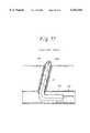
- An example of applying the above-mentioned method to a branch pipeis illustrated in FIG. 17.
- FIG. 17is a cross-sectional view illustrating a conventional branch pipe lining method, wherein a pressure bag 113 for eversion is inserted into a main pipe 110. Since this pressure bag 113 must be eventually separated from a branch pipe liner bag 101, a sealed tube 130 must be connected to the pressure bag 113 for applying a pressure to the branch pipe liner bag 101.
- the pressure bag 113is supplied with compressed air or the like, and the sealed tube 130 and the branch pipe liner bag 101 are inserted inside out into a branch pipe 111. With the illustrated state maintained, a hardenable resin impregnated in the branch pipe liner bag 111 is hardened. Then, the sealed tube 130 is pulled out of the branch pipe 111 (branch pipe liner bag 101), the inner wall of the branch pipe 111 is lined with the hardened branch pipe liner bag 111, thus repairing the branch pipe 111.
- a sealed tube of an appropriate lengthmust be prepared for a branch pipe of a different-length each time a different branch pipe is repaired, thus requiring a replacement of a sealed tube for each branch pipe.
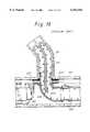
- FIGS. 18 and 19a branch pipe lining method illustrated in FIGS. 18 and 19 has been previously proposed by the present inventors.
- FIGS. 18 and 19are cross-sectional views illustrating that previously proposed branch pipe lining method.
- an air-tight connection between a pressure bag 213 and a branch pipe liner bag 201is provided by a tear-off tube 230, one end of which is temporarily bonded to the branch pipe liner bag 201.
- a guide tube 231is disposed in a main pipe 210, and an air mat 232 is used to urge a flange 203 of the branch pipe liner bag 201 onto the inner wall surface of the main pipe 210.
- an in-pipe work robot 212has been introduced in the main pipe 210.
- the branch pipe liner bag 201when a pressure bag 213 is supplied with compressed air with the flange 203 of the branch pipe liner bag 201 maintained pressed onto the inner wall of the main pipe 210, the branch pipe liner bag 201 is everted and inserted into the branch pipe 211 in a direction indicated by a white arrow by the action of the compressed air which applies a pressure to the branch pipe 21.
- a hardenable resin impregnated in the branch pipe liner bag 201is hardened to line the branch pipe 211 with the hardened branch pipe liner bag 201, thus repairing the branch pipe 211.
- the pressure bag 23is moved in a direction indicated by a horizontal arrow as illustrated in FIG. 19. Since the pressure bag 213 and the robot 212 are linked together by the-guide tube 231, the robot 212 is also moved in the same direction.
- the tear-off tube 230 temporarily bonded to the branch pipe liner bag 201is torn off the temporarily bonded portion, and separated from the branch pipe liner bag 201.
- the same tear-off tube 230can be used even if a branch pipe of a different length is to be lined, thus eliminating the replacement of the sealed tube 130 in the method illustrated in FIG. 17.
- the tear-off tube 230when the tear-off tube 230 is torn off, the tear-off tube 230 may not be completely removed from the branch pipe linear bag 201 with a portion thereof remaining on the inner wall of the branch pipe liner bag 201.
- the remaining portion of the tear-off tube 230acts as unwanted flash which causes problems such as a deteriorated inner wall surface of the branch pipe 211, attachment of flowing substances within the branch-pipe 211 to the flash, and so on.
- This inventionhas been made in view of the problems mentioned above, and its principal object is to provide an improved branch pipe liner bag and also a branch pipe lining method.
- It is a further object of this inventionis to provide a branch pipe liner bag and a branch pipe lining method which are capable of maintaining a satisfactory condition of the inner surface of a lined branch pipe.
- the branch pipe liner bagcomprises a tubular resin-absorbent material having a flange formed at one end thereof, the outer surface of the tubular resin-absorbent material being covered with a fluid-tight film, the tubular resin-absorbent material being impregnated with an unhardened hardenable resin, and a cylindrical member attached to the inner surface of the tubular resin-absorbent material and having a sealing surface which is capable of receiving an urging force to seal a fluid pressure.
- the branch pipe lining methoduses a branch pipe liner bag comprised of a tubular resin-absorbent material having a flange formed at one end thereof, the outer surface of the tubular resin-absorbent material being covered with a fluid-tight film, the tubular resin-absorbent material being impregnated with an unhardened hardenable resin.
- a cylindrical memberis attached to the inner surface of the tubular resin-absorbent material and has a sealing surface which is capable of receiving an urging force to seal a fluid pressure
- the methodcomprised the steps of (1) inserting a cylindrical front end nozzle attached to an opening at one end of a pressure bag into the cylindrical member of the branch pipe liner bag, the pressure bag accommodating the tubular resin absorbent material of the branch pipe liner bag except for the flange, (2) sealing the front end nozzle and the cylindrical member by an elastic member interposed therebetween, (3) bringing the flange of the branch pipe liner bag into close contact with an opening of a branch pipe, (4) supplying a pressurized fluid into the pressure bag to evert and insert the branch pipe liner bag into the branch pipe from a main pipe toward the ground, (5) hardening the hardenable resin impregnated in the branch pipe liner bag with the inserted branch pipe liner bag being pressed onto an inner wall of the branch pipe and (6) separating the front end nozzle from the cylindrical member to remove the pressure bag from the branch pipe liner bag.
- a fluid-tight or air-tight connection between the pressure bag and the branch pipe liner bagis made by the elastic member interposed between the front end nozzle and the fluid pressure sealing member.
- the front nozzleis separated from the cylindrical member to remove the pressure bag from the branch pipe liner bag.
- a tear-off tubeis no longer required and the branch pipe liner bag is only left in the branch pipe to maintain a favorable surface state of the lined branch pipe.
- FIG. 1is a cross-sectional view illustrating a branch pipe liner bag according to one embodiment of this invention.
- FIG. 2is an enlarged cross-sectional view illustrating a flange portion of the branch pipe liner bag according to the embodiment of this invention.
- FIGS. 3-7are cross-sectional views each illustrating a branch pipes liner bag according to various alternative embodiments of this invention.
- FIGS. 8-11are cross-sectional views illustrating in order various steps of a branch pipe lining method according to this invention.
- FIGS. 12-16are partial cross-sectional views illustrating sealed states during a branch pipe lining operation using the branch pipe liner bags illustrated in FIGS. 3, 4, 5, 6 and 7.
- FIGS. 17-19are cross-sectional views illustrating in order various steps of a conventional branch pipe lining method.
- FIG. 1is a cross-sectional view illustrating a branch pipe liner bag 1 according to an embodiment of this invention.
- FIG. 2is an enlarged cross-sectional view illustrating a flange of the branch pipe liner bag illustrated in FIG. 1.
- the branch pipe liner bag 1 illustrated in FIG. 1includes a tubular resin-absorbent material 2 impregnated with an unhardened hardenable resin, one end of which is folded out to form a hardened flange 3 integrally with the folded portion.
- the tubular resin absorbent material 2has its outer surface coated with a highly airtight plastic film 4. It should be noted that the flange 3 maintains an arcuate form conformal with the shape of the inner wall of a main pipe 10 (see FIG. 8) by previously hardening a hardenable resin impregnated therein.
- a material for the unwoven fabric constituting the tubular resin absorbent material 2may be selected from polyester, polypropylene, nylon, acrylic fabric, vinylon or the like.
- the hardenable resin impregnated in the tubular resin absorbent material 2may be unsaturated polyester resin, epoxy resin, vinyl ester resin, or the like.
- a material for the plastic film 4may be selected from polyethylene, vinyl chloride, vinylon, polyurethane, nylon, polypropylene, copolymers of polyethylene and nylon, and so on.
- a cylindrical air pressure sealing member 5is attached to the inner surface of the branch pipe liner bag 1 adjacent to the flange 3.
- the cylindrical member 5is integrally molded by an injection method using metal or hard plastic.
- a ring-shaped flange 5ais formed around the outer periphery of the fluid pressure sealing member 5 at an intermediate height position.
- a protrusion 5b extending upwardly from the flange 5aprotrudes into a branch pipe 11 (see FIG. 8) after the completion of a branch pipe lining operation, while a protrusion 5c extending downwardly from the flange 5a protrudes into the main pipe 10 after the completion of the branch pipe lining operation.
- the cylindrical member 5has its flange 5a sandwiched by the flange 3 of the branch pipe liner bag 1 as illustrated to be attached to an inner wall portion adjacent to the flange 3 as mentioned above.
- the inner surface of the cylindrical member 5constitutes a sealing wall surface which receives an urging force from an elastic body 17 (see FIG. 8) to seal a fluid pressure.
- the hardened hardenable resin impregnated in the flange of the branch pipe liner bag 1forms a hardened portion of a height h at a position adjacent to the flange 3 of the tubular resin absorbent material 2.
- the height h of this hardened portionvaries in the circumferential direction and is not constant.
- the tubular resin absorbent material of the conventional branch pipe liner bagis generally bent at a different height (corresponding to a height H in FIG. 2) whenever a branch pipe is lined with such a branch pipe liner bag.
- the height H of the bent portion of the branch pipe liner bagis preferably larger.
- an excessively large heightwould cause a problem in that the bent portion of the branch pipe liner bag, introduced into the main pipe by a remotely controlled robot might come in contact with the inner wall of the branch-pipe, resulting in damaging the branch pipe liner bag.
- the height H of the bent portion of the branch pipe liner bagtherefore should be set at a maximum value within a range in which the bent portion of the branch pipe liner bag does not come in contact with the inner wall of the main pipe during the transportation of the branch pipe liner bag into the main pipe. Such setting, however, is virtually impossible due reason set forth above.
- the tubular resin absorbent material 2abuts to the upper end of the protrusion 5b of the cylindrical member 5, extending upwardly from the upper surface of the flange 3 by a height H 1 (h ⁇ H 1 ⁇ H).
- the tubular resin absorbent material 2is bent by the protrusion 5b of the fluid pressure sealing member 5 at a height H which is always constant irrespective of the height h of the hardened portion, so that the bending height H can be maintained at an optimal value (a maximum value available without causing a contact with the inner wall of the main pipe 10).
- branch pipe liner bagsaccording to other embodiments will be described with reference to FIGS. 3-7.
- a branch pipe liner bag 1 illustrated in FIG. 3includes a cylindrical air pressure sealing member 5 secured to a flange 3 with a plurality of bolts 6 and nuts 7. More specifically, a flange 5a of the cylindrical member 5 is pressed onto the lower surface of the flange 3, and the cylindrical member 5 is secured to the flange 3 with a plurality of the bolts 6 extending through the flange 5a and the flange 3 and the same plurality of the nuts 7 engaged with the respective bolts 6.
- the cylindrical member 5 of this embodimentalso has 5b, 5c extending upwardly and downwardly, respectively.
- a branch pipe liner bag 1 illustrated in FIG. 4has a fluid pressure sealing member 5 attached thereto in a similar manner to that illustrated in FIG. 1. Additionally, the cylindrical member 5 has its upper end portion bent inwardly to form a bent end portion 5d which defines a space or a pocket formed in a inverted C shape in cross-section.
- the fluid pressure sealing member 5 of this embodimentalso has protrusions 5b, 5c extending upwardly and downwardly, respectively.
- Branch pipe liner bags 1 illustrated in FIGS. 5-7each have another flange 8, separate from a branch pipe liner bag 2, attached to one end of the branch pipe liner bag 2.
- the flange 8also serves as a fluid pressure sealing member.
- the flange 8is integrally molded by an injection method using metal or hard plastic.
- one end of the tubular resin absorbent material 2is folded out, fit into a cylindrical protrusion 8a of the flange 8 (a portion protruding into a branch pipe 11 after a branch pipe lining operation is completed), and fixedly fastened by a band 9.
- This flange 8does not have a protrusion protruding into a main pipe 10 after the branch pipe lining operation is completed.
- the branch pipe liner bag 1 illustrated in FIG. 6also has a flange 8 attached to one end portion of a tubular resin absorbent material 2, which is folded out, in a manner similar to the branch pipe liner bag 1 illustrated in FIG. 5.
- This branch pipe liner bag 1differs from that illustrated in FIG. 5 in that the flange 8 has both of a protrusion 8a protruding into a branch pipe 11 and a protrusion 8b protruding into a main pipe 10 after a branch pipe lining operation is completed.
- the branch pipe liner bag illustrated in FIG. 7has a flange 8 composed of upper and lower separate pieces 8A, 8B.
- One end of a tubular resin absorbent material 2, which is folded out,is extended outwardly, and the extended portion is sandwiched by the upper and lower separate pieces 8A, 8B.
- the upper and lower separate pieces 8A, 8B of the flange 8 and the extended end portion of the tubular resin absorbent material 2are integrally fastened by a plurality of bolts 6 extending therethrough and the same plurality of nuts 7 engaged with the respective bolts 6.
- the upper and lower separate pieces 8A, 8B of the flange 8are formed with cylindrical protrusions 8c, 8d, respectively, which protrude into a branch pipe 11 after a branch pipe lining operation is completed.
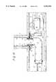
- FIGS. 8-11are cross-sectional views illustrating in at various steps of the branch pipe lining method of this invention.
- a main pipe 10 of a sewage pipe line or the likehas a branch pipe 11, having a smaller diameter, confluent thereto.
- an in-pipe work robot 12Within the main pipe 10, an in-pipe work robot 12, a pressure bag 13 for eversion, the branch pipe liner bag 1 and so on have been introduced for operations associated with the branch pipe lining method.
- the robot 12is hydraulically driven.
- a hydraulic cylinder 14is attached to a head portion 12a of the robot 12, and a setting arm 15 is attached to a vertically sliceable rod 14a (see FIG. 9) of the hydraulic cylinder 14.
- a cylindrical front end nozzle 16extends through and is supported by the setting arm 15.
- a ring-shaped elastic member 17is fitted on the top outer periphery of the front end nozzle 16, while an opening at one end of the pressure bag 13 is attached to the outer periphery of the lower end of the front end nozzle 16.
- a hydraulic hose 18 and a pull rope 19are attached to the robot 12, and a TV camera 20 for monitoring is installed on the top of the robot 12.
- the hydraulic hose 18is connected to a hydraulic pump, not shown, installed on the ground, while the TV camera 20 is connected to a monitor, not shown, similarly installed on the ground, through an electric cable 21.
- the pressure bag 13has the other end (closed end) connected with an air hose 22 and a pull rope 23.
- the air hose 22is connected to a compressor, not shown, installed on the ground.
- the branch pipe liner bag 1has its flange 3 set on the setting arm 15, and the uneverted tubular resin absorbent material 2 except for the flange 3 is accommodated in the pressure bag 13.
- the front end nozzle 16is inserted into the cylindrical member 5 of the branch pipe liner bag 1 from below, wherein the elastic member 17 fitted on the top outer periphery of the front end nozzle 11 is pressed onto the inner wall of the cylindrical member 5 to provide air-tight sealing between the front end nozzle 16 and the cylindrical member 5.
- the inner surface of the cylindrical member 5constitutes a sealed wall surface which receives an urging force of the elastic member 17 to seal the air pressure.
- the pull rope 23is pulled, for example, to the left (indicated by an arrow) as illustrated in FIG. 8 to move the integrally assembled robot 12, pressure bag 13, branch pipe liner bag 1 and so on in the same direction inside the main pipe 10.
- the bending height H (see FIG. 2) of the branch pipe liner bag 1is maintained at an optimal value (a maximum value available without causing a contact with the inner wall of the main pipe 10) as mentioned above, the branch pipe liner bag never come into contact with the main pipe 1 to get damaged thereby.
- the flange 3 of the branch pipe liner bag 1is positioned at an opening of the branch pipe as illustrated in FIG. 9, while monitoring the operation on the ground through the TV camera 20 installed on the robot 12. Subsequently, the rod 14a of the hydraulic cylinder 14 is elevated to bring the flange 3 of the branch pipe liner bag 1 into close contact with the periphery of the opening of the branch pipe 11. Since the branch pipe liner bag 1 has the bending height H (see FIG. 2) fixed at the optimal value (a maximum value available without causing a contact with the inner wall of the main pipe 10) as mentioned above, the flange 3 can be readily and reliably positioned.
- a closed space S defined by the branch pipe liner bag 1is formed within the pressure bag 13. Since the front end nozzle 16 and the cylindrical member 5 are air-tight sealed by the elastic member 17, a high sealability is ensured for the closed space S.
- a compressornot shown, installed on the ground is driven to supply compressed air into the closed space S within the pressure bag 13 from the air hose 22, causing the tubular resin absorbent material 2 of the branch pipe liner bag 1 to be everted and inserted into the branch pipe 11 from the main pipe side, as indicated by broken lines in FIG. 9, by the pressure of the compressed air applied to tubular resin absorbent material 2.
- the rod 14a of the hydraulic cylinder 14is lowered and the front end nozzle 16 is pulled out from the fluid-pressure sealing member 5 of the branch pipe liner bag 1.
- an air-tight connection between the pressure bag 13 and the branch pipe liner bag 1is made by the elastic member 17 interposed between the front end nozzle 16 and the fluid pressure sealing member 5.
- the front nozzle 16is pulled out from the cylindrical member S to separate the pressure bag 13 from the branch pipe liner bag 1.
- a tear-off tubeseparable tube
- FIGS. 12-16sealing states of the branch pipe liner bags previously illustrated in FIGS. 3-7 during a branch pipe lining operation are illustrated in partial cross-sectional views of FIGS. 12-16, respectively.
- the front end nozzle 16 having the ring-shaped elastic member 17 secured around the inner periphery of the top end thereofis inserted into the protrusion 5c of the cylindrical member 5 from below and fitted on the outer periphery of the protrusion 5c, with the elastic member pressed onto the outer surface of the protrusion 5c.
- the front end nozzle 16 and the cylindrical member 5are air-tight sealed by the elastic member 17.
- the elastic 17also provides an air-tight connection between the pressure bag 13 and the branch pipe liner bag 1.
- the outer surface of the protrusion 5c of the cylindrical member 5constitutes a sealing wall surface which receives an urging force of the elastic member 17 to seal the air pressure.
- the front end nozzle 16 having ringshaped elastic members 17a, 17b secured around the inner periphery and the outer periphery of the top end thereofis inserted into a space defined by a bent portion 15d in an upper end section of the cylindrical member 5 from below.
- the elastic member 17bis connected to a compressor 26 through an air hose 25 such that compressed air is supplied from the compressor 25 to the elastic member 17b through the air hose 24 to inflate the elastic member 17b.
- both the elastic members 17a, 17bare pressed onto the front end nozzle 16 and the cylindrical member S with a more strong force, so that the front end nozzle 16 and the cylindrical member S are more reliably sealed by the two elastic members 17a, 17b, thereby providing a secure air-tight connection between the pressure bag 13 and the branch pipe liner bag 1 by the action of the elastic members 17a, 17b.
- the front end nozzle 16 having the ring-shaped elastic member 17 fitted on the outer periphery of a top end portion thereofis inserted into the protrusion 8a of the flange 8, serving also as an air pressure sealing member, from below, and the elastic member 17 is pressed onto the inner surface of the protrusion 8a, so that the front end nozzle 16 and the flange 8 are air-tight sealed by the elastic member 17.
- the elastic member 17also provides an air-tight connection between the pressure bag 13 and the branch pipe liner bag 1.
- the inner surface of the protrusion 8a of the flange 8constitutes a sealing wall surface which receives an urging force of the elastic member 17 to seal a fluid pressure.
- the front end nozzle 16 having the ring-shaped elastic member 17 secured around the inner periphery of a top end portion thereofis fitted on the protrusion 8b of the flange 8, serving also as an air pressure sealing member, from below, and the elastic member 17 is pressed onto the outer surface of the protrusion 8b, so that the front end nozzle 16 and the flange 8 are air-tight sealed by the elastic member 17.
- the elastic member 17also provides an air-tight connection between the pressure bag 13 and the branch pipe liner bag 1.
- the outer surface of the protrusion 8b of the flange 8constitutes a sealing wall surface which receives an urging force of the elastic member 17 to seal pressure.
- the front end nozzle 16 having the ring-shaped elastic member 17 fitted on the outer periphery of a top end thereofis inserted into the separate piece 8B of the flange 8 from below.
- the elastic member 17is connected to a compressor 25 through an air hose 24, such that compressed air is supplied from the compressor 25 to the elastic member 17 through the air hose 24 to inflate the elastic member 17. This causes the elastic member 17 to urge onto the inner surface of the separate piece 8B of the flange 8, thereby more reliably sealing the front end nozzle 16 and the flange 8 by the action of the elastic member 17.
- the elastic member 17provides a secure air-tight connection between the pressure bag 13 and the branch pipe liner bag 1, so that the front end nozzle 16 and the flange 8 are air-tight sealed by the elastic member 17.
- the elastic member 17also provides an air-tight connection between the pressure bag 13 and the branch pipe liner bag 1.
- the inner surface of the protrusion 8d of the separate piece 8B of the flange 8constitutes a sealing wall surface which receives an urging force of the elastic member 17 to seal the air pressure.
- an air-tight connection or fluid-tight connection between the pressure bag and the branch pipe liner bagis made by the elastic member interposed between the front end nozzle and the cylindrical fluid pressure sealing member.
- the front nozzleis pulled out from the fluid pressure sealing member to separate the pressure bag from the branch pipe liner bag.
- any tear-off tubewhich has been conventionally required, is no longer necessary for the branch pipe lining method. Consequently, the branch pipe liner bag is only left in the branch pipe to maintain a favorable surface state of the lined branch pipe.
Landscapes
- Engineering & Computer Science (AREA)
- General Engineering & Computer Science (AREA)
- Mechanical Engineering (AREA)
- Manufacturing & Machinery (AREA)
- Lining Or Joining Of Plastics Or The Like (AREA)
- Protection Of Pipes Against Damage, Friction, And Corrosion (AREA)
- Pipe Accessories (AREA)
Abstract
Description
Claims (22)
Applications Claiming Priority (2)
| Application Number | Priority Date | Filing Date | Title |
|---|---|---|---|
| JP10-048011 | 1998-02-27 | ||
| JP04801198AJP3971013B2 (en) | 1998-02-27 | 1998-02-27 | Branch pipe lining method |
Publications (1)
| Publication Number | Publication Date |
|---|---|
| US6152184Atrue US6152184A (en) | 2000-11-28 |
Family
ID=12791372
Family Applications (1)
| Application Number | Title | Priority Date | Filing Date |
|---|---|---|---|
| US09/247,631Expired - Fee RelatedUS6152184A (en) | 1998-02-27 | 1999-02-10 | Branch pipe liner bag and branch pipe lining method |
Country Status (6)
| Country | Link |
|---|---|
| US (1) | US6152184A (en) |
| EP (1) | EP0938964B1 (en) |
| JP (1) | JP3971013B2 (en) |
| KR (1) | KR19990072814A (en) |
| DE (1) | DE69916681T2 (en) |
| DK (1) | DK0938964T3 (en) |
Cited By (20)
| Publication number | Priority date | Publication date | Assignee | Title |
|---|---|---|---|---|
| US6484757B1 (en) | 2002-03-19 | 2002-11-26 | Liqui-Force Sewer Services Inc. | Method and device for lining a lateral sewer pipe |
| US20030116211A1 (en)* | 2001-12-19 | 2003-06-26 | Ward Robert M. | Apparatus and method for the robotic repairing of an underground pipe junction with a flexible patch mechanism |
| US6631739B2 (en)* | 2000-05-18 | 2003-10-14 | Shonan Gosei-Jushi Seisakusho K.K. | Pipe liner bag everting nozzle and pipe lining method |
| US6651699B2 (en)* | 2001-12-12 | 2003-11-25 | Tae-Joo Kweon | Liner for branch pipe of old repaired pipe and lining system and method for such liner |
| US20040020544A1 (en)* | 2002-04-05 | 2004-02-05 | Takao Kamiyama | Pressure bag and method of lining branch pipe |
| US20050092382A1 (en)* | 2003-09-25 | 2005-05-05 | Epros Gmbh | Device and method for pipeline rehabilitation |
| US20060130922A1 (en)* | 2004-10-27 | 2006-06-22 | Shonan Gosei-Jushi Seisakusho K.K. | Lateral pipe lining material and lateral pipe lining method |
| US20070163665A1 (en)* | 2006-01-18 | 2007-07-19 | William Lepola | Vertical pipe lining method and system |
| US20080169036A1 (en)* | 2007-01-12 | 2008-07-17 | Takao Kamiyama | Lateral pipe lining material and lateral pipe lining method using same |
| US20080245433A1 (en)* | 2007-04-03 | 2008-10-09 | Darcy Warren | Lateral liner with seal |
| US20120060346A1 (en)* | 2010-09-10 | 2012-03-15 | Shonan Gosei-Jushi Seisakusho K.K. | Lateral pipe lining method and lateral pipe lining apparatus |
| US20140314492A1 (en)* | 2013-03-14 | 2014-10-23 | SAK Construction, LLC | Systems And Apparatus For Inhibiting A Compressed Pipe Liner From Retreating Into A Host Pipe |
| US20150328857A1 (en)* | 2012-12-07 | 2015-11-19 | Ashimori Industry Co., Ltd. | Lining material for conduit and lining method for conduit |
| US9593785B2 (en) | 2014-02-20 | 2017-03-14 | Dr. Ing. H.C.F. Porsche Aktiengesellschaft | Connection method for a braided hose |
| WO2017083531A1 (en)* | 2015-11-10 | 2017-05-18 | Lmk Technologies, Llc | Method and apparatus for repairing a pipe junction |
| US20180031167A1 (en)* | 2016-07-28 | 2018-02-01 | BLD Services, LLC | Pipe lining systems and methods of use |
| US9933105B1 (en)* | 2017-04-12 | 2018-04-03 | InnerCure Technologies, LLC | Underground pipe repair device with radial stepped annular spacer and related systems and methods |
| US10309575B2 (en) | 2017-04-12 | 2019-06-04 | Inner Cure Technologies | Underground pipe repair device with radial annular spacers and related systems and methods |
| US10514125B1 (en) | 2017-04-12 | 2019-12-24 | InnerCure Technologies, LLC | Underground pipe repair device with retention device and related systems and methods |
| US11326732B2 (en) | 2017-04-12 | 2022-05-10 | improved Infrastructure Solutions, LLC | Underground pipe repair device with detectable annular body and related systems and methods |
Families Citing this family (7)
| Publication number | Priority date | Publication date | Assignee | Title |
|---|---|---|---|---|
| JP3746972B2 (en)* | 2001-09-11 | 2006-02-22 | 積水化学工業株式会社 | How to shut off the mounting pipe port |
| DE102005036334B4 (en)* | 2005-07-29 | 2010-01-21 | Dieter Meier | Inversion device and method for introducing an inliner into a pipeline to be rehabilitated |
| JP4806835B2 (en)* | 2009-07-22 | 2011-11-02 | 有限会社横島 | Pipe lining method and lining pipe |
| DE102014010431A1 (en)* | 2014-07-16 | 2016-01-21 | Street To Home Gmbh & Co. Kg | Method for rehabilitating an underground line opening into a main channel |
| JP5844875B2 (en)* | 2014-11-27 | 2016-01-20 | 株式会社湘南合成樹脂製作所 | Branch pipe lining method and branch pipe lining apparatus |
| DE102016209246A1 (en) | 2016-05-27 | 2017-11-30 | Verica Meier | Lining device for lining a channel branch line |
| DE102018121098A1 (en)* | 2018-08-29 | 2020-03-05 | AWT Decker GmbH | Process for the repair of a pipeline on a watercraft or a structure at sea, and pipeline of a watercraft or a structure at sea |
Citations (12)
| Publication number | Priority date | Publication date | Assignee | Title |
|---|---|---|---|---|
| US3968552A (en)* | 1974-10-24 | 1976-07-13 | Hunter John J | Method and apparatus for forming plastic lined junction in lined pipe |
| US5329063A (en)* | 1991-05-31 | 1994-07-12 | Get, Inc. | Liner assembly for lining branch pipes and a method for manufacturing the liner assembly |
| US5439033A (en)* | 1993-09-28 | 1995-08-08 | Shonan Gosei-Jushi Seisakusho K.K. | Method of lining a branch pipe |
| US5454401A (en)* | 1993-08-31 | 1995-10-03 | Shonan Gosei-Jushi Seisakusho K.K. | Method of lining a branch pipe |
| US5498389A (en)* | 1993-03-23 | 1996-03-12 | Shonan Gosei-Jushi Seisakusho K.K. | Method and apparatus for lining a branch pipe |
| US5566719A (en)* | 1994-07-05 | 1996-10-22 | Shonan Gosei-Jushi Seisakusho K.K. | Method for lining a branch pipe of an underground pipe |
| US5700100A (en)* | 1997-02-20 | 1997-12-23 | Risdon Corporation | Mascara container having a stirrer and a separate wiper |
| US5916406A (en)* | 1996-02-14 | 1999-06-29 | Shonan Gosei-Jushi Seisakusho Kk | Branch pipe liner bag and pipe lining method |
| US5944058A (en)* | 1997-02-04 | 1999-08-31 | Shonan Gosei-Jushi Seisakusho K.K. | Branch pipe liner assembly and a pipe lining method |
| US5967192A (en)* | 1995-08-04 | 1999-10-19 | Kanal Technik Ingenieurburo | Process and device for refurbishing drains |
| US5971031A (en)* | 1997-10-06 | 1999-10-26 | Shona Gosei-Jushi Seiksakusho K.K. | Branch pipe liner bag and pipe lining method |
| US6006787A (en)* | 1998-02-12 | 1999-12-28 | Shonan Gosei-Jushi Seisakusho K.K. | Branch pipe liner bag and branch pipe lining method |
Family Cites Families (3)
| Publication number | Priority date | Publication date | Assignee | Title |
|---|---|---|---|---|
| JP2530553B2 (en)* | 1993-03-23 | 1996-09-04 | 株式会社湘南合成樹脂製作所 | Branch pipe lining method |
| JP2974132B2 (en)* | 1997-02-04 | 1999-11-08 | 株式会社湘南合成樹脂製作所 | Pipe lining method |
| JP2000052426A (en)* | 1998-08-06 | 2000-02-22 | Shonan Gosei Jushi Seisakusho:Kk | Branch pipe lining material and pipe lining method |
- 1998
- 1998-02-27JPJP04801198Apatent/JP3971013B2/ennot_activeExpired - Fee Related
- 1999
- 1999-02-10USUS09/247,631patent/US6152184A/ennot_activeExpired - Fee Related
- 1999-02-22KRKR1019990005754Apatent/KR19990072814A/ennot_activeAbandoned
- 1999-02-26DEDE69916681Tpatent/DE69916681T2/ennot_activeExpired - Fee Related
- 1999-02-26EPEP99301449Apatent/EP0938964B1/ennot_activeExpired - Lifetime
- 1999-02-26DKDK99301449Tpatent/DK0938964T3/enactive
Patent Citations (12)
| Publication number | Priority date | Publication date | Assignee | Title |
|---|---|---|---|---|
| US3968552A (en)* | 1974-10-24 | 1976-07-13 | Hunter John J | Method and apparatus for forming plastic lined junction in lined pipe |
| US5329063A (en)* | 1991-05-31 | 1994-07-12 | Get, Inc. | Liner assembly for lining branch pipes and a method for manufacturing the liner assembly |
| US5498389A (en)* | 1993-03-23 | 1996-03-12 | Shonan Gosei-Jushi Seisakusho K.K. | Method and apparatus for lining a branch pipe |
| US5454401A (en)* | 1993-08-31 | 1995-10-03 | Shonan Gosei-Jushi Seisakusho K.K. | Method of lining a branch pipe |
| US5439033A (en)* | 1993-09-28 | 1995-08-08 | Shonan Gosei-Jushi Seisakusho K.K. | Method of lining a branch pipe |
| US5566719A (en)* | 1994-07-05 | 1996-10-22 | Shonan Gosei-Jushi Seisakusho K.K. | Method for lining a branch pipe of an underground pipe |
| US5967192A (en)* | 1995-08-04 | 1999-10-19 | Kanal Technik Ingenieurburo | Process and device for refurbishing drains |
| US5916406A (en)* | 1996-02-14 | 1999-06-29 | Shonan Gosei-Jushi Seisakusho Kk | Branch pipe liner bag and pipe lining method |
| US5944058A (en)* | 1997-02-04 | 1999-08-31 | Shonan Gosei-Jushi Seisakusho K.K. | Branch pipe liner assembly and a pipe lining method |
| US5700100A (en)* | 1997-02-20 | 1997-12-23 | Risdon Corporation | Mascara container having a stirrer and a separate wiper |
| US5971031A (en)* | 1997-10-06 | 1999-10-26 | Shona Gosei-Jushi Seiksakusho K.K. | Branch pipe liner bag and pipe lining method |
| US6006787A (en)* | 1998-02-12 | 1999-12-28 | Shonan Gosei-Jushi Seisakusho K.K. | Branch pipe liner bag and branch pipe lining method |
Cited By (39)
| Publication number | Priority date | Publication date | Assignee | Title |
|---|---|---|---|---|
| US7051766B2 (en) | 2000-05-18 | 2006-05-30 | Takao Kamiyama | Pipe liner bag everting nozzle and pipe lining method |
| US6631739B2 (en)* | 2000-05-18 | 2003-10-14 | Shonan Gosei-Jushi Seisakusho K.K. | Pipe liner bag everting nozzle and pipe lining method |
| US20040045617A1 (en)* | 2000-05-18 | 2004-03-11 | Takao Kamiyama | Pipe liner bag everting nozzle and pipe lining method |
| US6651699B2 (en)* | 2001-12-12 | 2003-11-25 | Tae-Joo Kweon | Liner for branch pipe of old repaired pipe and lining system and method for such liner |
| US20030116211A1 (en)* | 2001-12-19 | 2003-06-26 | Ward Robert M. | Apparatus and method for the robotic repairing of an underground pipe junction with a flexible patch mechanism |
| US6688337B2 (en)* | 2001-12-19 | 2004-02-10 | Robert M. Ward | Apparatus and method for the robotic repairing of an underground pipe junction with a flexible patch mechanism |
| US6695013B2 (en) | 2002-03-19 | 2004-02-24 | Liqui-Force Sewer Services, Inc. | Method and device for lining a lateral sewer pipe |
| US6484757B1 (en) | 2002-03-19 | 2002-11-26 | Liqui-Force Sewer Services Inc. | Method and device for lining a lateral sewer pipe |
| US20040020544A1 (en)* | 2002-04-05 | 2004-02-05 | Takao Kamiyama | Pressure bag and method of lining branch pipe |
| US20100043903A1 (en)* | 2003-09-25 | 2010-02-25 | Muehlin Michael | Device and method for pipeline rehabilitation |
| US7631665B2 (en)* | 2003-09-25 | 2009-12-15 | Trelleborg Pipe Seals Duisburg Gmbh | Device and method for pipeline rehabilitation |
| US8499798B2 (en)* | 2003-09-25 | 2013-08-06 | Trelleborg Pipe Seals Duisburg Gmbh | Device and method for pipeline rehabilitation |
| US20050092382A1 (en)* | 2003-09-25 | 2005-05-05 | Epros Gmbh | Device and method for pipeline rehabilitation |
| US7311121B2 (en) | 2004-10-27 | 2007-12-25 | Shonan Gosei-Jushi Seisakusho K.K. | Lateral pipe lining material and lateral pipe lining method |
| US20060130922A1 (en)* | 2004-10-27 | 2006-06-22 | Shonan Gosei-Jushi Seisakusho K.K. | Lateral pipe lining material and lateral pipe lining method |
| US20070163665A1 (en)* | 2006-01-18 | 2007-07-19 | William Lepola | Vertical pipe lining method and system |
| US7527076B2 (en)* | 2006-01-18 | 2009-05-05 | Energy Maintenance Service Group I Llc | Vertical pipe lining method and system |
| US20080169036A1 (en)* | 2007-01-12 | 2008-07-17 | Takao Kamiyama | Lateral pipe lining material and lateral pipe lining method using same |
| US7503349B2 (en)* | 2007-01-12 | 2009-03-17 | Shonan Gosei-Jushi Seisakusho K.K. | Lateral pipe lining material and lateral pipe lining method using same |
| US8316892B2 (en) | 2007-04-03 | 2012-11-27 | Liqui-Force Sewer Services Inc. | Lateral liner with seal |
| US20080245433A1 (en)* | 2007-04-03 | 2008-10-09 | Darcy Warren | Lateral liner with seal |
| US20120060346A1 (en)* | 2010-09-10 | 2012-03-15 | Shonan Gosei-Jushi Seisakusho K.K. | Lateral pipe lining method and lateral pipe lining apparatus |
| US8635753B2 (en)* | 2010-09-10 | 2014-01-28 | Shonan Gosei-Jushi Seisakusho K.K. | Lateral pipe lining method and lateral pipe lining apparatus |
| US20150328857A1 (en)* | 2012-12-07 | 2015-11-19 | Ashimori Industry Co., Ltd. | Lining material for conduit and lining method for conduit |
| US9962900B2 (en)* | 2012-12-07 | 2018-05-08 | Ashimori Industry Co., Ltd. | Lining material for conduit and lining method for conduit |
| US9377149B2 (en)* | 2013-03-14 | 2016-06-28 | SAK Construction, LLC | Systems and apparatus for inhibiting a compressed pipe liner from retreating into a host pipe |
| US20140314492A1 (en)* | 2013-03-14 | 2014-10-23 | SAK Construction, LLC | Systems And Apparatus For Inhibiting A Compressed Pipe Liner From Retreating Into A Host Pipe |
| US9593785B2 (en) | 2014-02-20 | 2017-03-14 | Dr. Ing. H.C.F. Porsche Aktiengesellschaft | Connection method for a braided hose |
| WO2017083531A1 (en)* | 2015-11-10 | 2017-05-18 | Lmk Technologies, Llc | Method and apparatus for repairing a pipe junction |
| US20170146178A1 (en)* | 2015-11-10 | 2017-05-25 | Lmk Technologies, Llc | Method and Apparatus for Repairing a Pipe Junction |
| US10767805B2 (en)* | 2016-07-28 | 2020-09-08 | BLD Services, LLC | Pipe lining systems and methods of use |
| US20180031167A1 (en)* | 2016-07-28 | 2018-02-01 | BLD Services, LLC | Pipe lining systems and methods of use |
| US11933445B2 (en) | 2016-07-28 | 2024-03-19 | BLD Services, LLC | Pipe lining systems and methods of use |
| US11560975B2 (en) | 2016-07-28 | 2023-01-24 | BLD Services, LLC | Pipe lining systems and methods of use |
| US9933105B1 (en)* | 2017-04-12 | 2018-04-03 | InnerCure Technologies, LLC | Underground pipe repair device with radial stepped annular spacer and related systems and methods |
| US11035514B1 (en) | 2017-04-12 | 2021-06-15 | improved Infrastructure Solutions, LLC | Underground pipe repair device with annular spacer and related systems and methods |
| US11326732B2 (en) | 2017-04-12 | 2022-05-10 | improved Infrastructure Solutions, LLC | Underground pipe repair device with detectable annular body and related systems and methods |
| US10514125B1 (en) | 2017-04-12 | 2019-12-24 | InnerCure Technologies, LLC | Underground pipe repair device with retention device and related systems and methods |
| US10309575B2 (en) | 2017-04-12 | 2019-06-04 | Inner Cure Technologies | Underground pipe repair device with radial annular spacers and related systems and methods |
Also Published As
| Publication number | Publication date |
|---|---|
| JPH11245302A (en) | 1999-09-14 |
| DK0938964T3 (en) | 2004-07-26 |
| DE69916681T2 (en) | 2005-04-07 |
| EP0938964A3 (en) | 2001-01-31 |
| KR19990072814A (en) | 1999-09-27 |
| JP3971013B2 (en) | 2007-09-05 |
| EP0938964B1 (en) | 2004-04-28 |
| DE69916681D1 (en) | 2004-06-03 |
| EP0938964A2 (en) | 1999-09-01 |
Similar Documents
| Publication | Publication Date | Title |
|---|---|---|
| US6152184A (en) | Branch pipe liner bag and branch pipe lining method | |
| EP0620102B1 (en) | Branch pipe lining method and liner | |
| US5454401A (en) | Method of lining a branch pipe | |
| US7311121B2 (en) | Lateral pipe lining material and lateral pipe lining method | |
| EP0650006B1 (en) | Method of lining a branch pipe | |
| US6056017A (en) | Pipe lining method | |
| US5964249A (en) | Apparatus and method for repairing a pipeline | |
| EP0691507B1 (en) | A method for lining a branch pipe of an underground pipe | |
| US6006787A (en) | Branch pipe liner bag and branch pipe lining method | |
| US6001212A (en) | Method for lining of lateral pipelines with flow-through apparatus | |
| CA3011292C (en) | Pipe junction repair assembly having frangible connections | |
| AU708872B2 (en) | A method for lining a bent pipe | |
| US6085794A (en) | Pipe lining method | |
| US6158473A (en) | Branch pipe liner bag and pipe lining method | |
| US5736166A (en) | Flow-through apparatus for lining of pipelines | |
| EP0620100B1 (en) | A method for everting a tubular liner bag | |
| EP0620101B1 (en) | Method and apparatus for lining a branch pipe | |
| US20040020544A1 (en) | Pressure bag and method of lining branch pipe | |
| JPH1120020A (en) | Branch pipe lining material and method for lining branch pipe using it | |
| JPH1034750A (en) | Lining material for duct | |
| KR19990013490A (en) | Branch pipe lining material and branch pipe lining method using the same |
Legal Events
| Date | Code | Title | Description |
|---|---|---|---|
| AS | Assignment | Owner name:YOKOSHIMA & COMPANY, JAPAN Free format text:ASSIGNMENT OF ASSIGNORS INTEREST;ASSIGNORS:KAMIYAMA, TAKAO;YOKOSHIMA, YASUHIRO;ENDOH, SHIGERU;AND OTHERS;REEL/FRAME:009757/0516;SIGNING DATES FROM 19990129 TO 19990201 Owner name:OAR COMPANY, JAPAN Free format text:ASSIGNMENT OF ASSIGNORS INTEREST;ASSIGNORS:KAMIYAMA, TAKAO;YOKOSHIMA, YASUHIRO;ENDOH, SHIGERU;AND OTHERS;REEL/FRAME:009757/0516;SIGNING DATES FROM 19990129 TO 19990201 Owner name:GET INC., JAPAN Free format text:ASSIGNMENT OF ASSIGNORS INTEREST;ASSIGNORS:KAMIYAMA, TAKAO;YOKOSHIMA, YASUHIRO;ENDOH, SHIGERU;AND OTHERS;REEL/FRAME:009757/0516;SIGNING DATES FROM 19990129 TO 19990201 Owner name:SHONAN GOSEI-JUSHI SEISAKUSHO K.K., JAPAN Free format text:ASSIGNMENT OF ASSIGNORS INTEREST;ASSIGNORS:KAMIYAMA, TAKAO;YOKOSHIMA, YASUHIRO;ENDOH, SHIGERU;AND OTHERS;REEL/FRAME:009757/0516;SIGNING DATES FROM 19990129 TO 19990201 | |
| CC | Certificate of correction | ||
| FEPP | Fee payment procedure | Free format text:PAYOR NUMBER ASSIGNED (ORIGINAL EVENT CODE: ASPN); ENTITY STATUS OF PATENT OWNER: SMALL ENTITY | |
| FPAY | Fee payment | Year of fee payment:4 | |
| FEPP | Fee payment procedure | Free format text:PAYOR NUMBER ASSIGNED (ORIGINAL EVENT CODE: ASPN); ENTITY STATUS OF PATENT OWNER: SMALL ENTITY Free format text:PAYER NUMBER DE-ASSIGNED (ORIGINAL EVENT CODE: RMPN); ENTITY STATUS OF PATENT OWNER: SMALL ENTITY | |
| FPAY | Fee payment | Year of fee payment:8 | |
| REMI | Maintenance fee reminder mailed | ||
| LAPS | Lapse for failure to pay maintenance fees | ||
| STCH | Information on status: patent discontinuation | Free format text:PATENT EXPIRED DUE TO NONPAYMENT OF MAINTENANCE FEES UNDER 37 CFR 1.362 | |
| FP | Lapsed due to failure to pay maintenance fee | Effective date:20121128 |