US6151486A - Magnetic latch and release device and radiotelephones incorporating same - Google Patents
Magnetic latch and release device and radiotelephones incorporating sameDownload PDFInfo
- Publication number
- US6151486A US6151486AUS09/182,682US18268298AUS6151486AUS 6151486 AUS6151486 AUS 6151486AUS 18268298 AUS18268298 AUS 18268298AUS 6151486 AUS6151486 AUS 6151486A
- Authority
- US
- United States
- Prior art keywords
- magnetic
- housing
- electronic device
- disposed
- conductive coil
- Prior art date
- Legal status (The legal status is an assumption and is not a legal conclusion. Google has not performed a legal analysis and makes no representation as to the accuracy of the status listed.)
- Expired - Lifetime
Links
- XEEYBQQBJWHFJM-UHFFFAOYSA-NIronChemical group[Fe]XEEYBQQBJWHFJM-UHFFFAOYSA-N0.000claimsdescription24
- 230000001939inductive effectEffects0.000claimsdescription17
- 229910052742ironInorganic materials0.000claimsdescription12
- 230000004913activationEffects0.000claimsdescription10
- 230000004044responseEffects0.000claimsdescription7
- 230000003213activating effectEffects0.000claims5
- 230000007246mechanismEffects0.000description16
- 230000004907fluxEffects0.000description8
- 239000003990capacitorSubstances0.000description3
- 230000004048modificationEffects0.000description3
- 238000012986modificationMethods0.000description3
- 230000000712assemblyEffects0.000description1
- 238000000429assemblyMethods0.000description1
- 230000001413cellular effectEffects0.000description1
- 238000006073displacement reactionMethods0.000description1
- 230000000694effectsEffects0.000description1
- 239000000696magnetic materialSubstances0.000description1
- 238000004519manufacturing processMethods0.000description1
- 239000000463materialSubstances0.000description1
- 238000004804windingMethods0.000description1
Images


Classifications
- H—ELECTRICITY
- H04—ELECTRIC COMMUNICATION TECHNIQUE
- H04M—TELEPHONIC COMMUNICATION
- H04M1/00—Substation equipment, e.g. for use by subscribers
- H04M1/02—Constructional features of telephone sets
- H04M1/0202—Portable telephone sets, e.g. cordless phones, mobile phones or bar type handsets
- H04M1/0206—Portable telephones comprising a plurality of mechanically joined movable body parts, e.g. hinged housings
- H04M1/0208—Portable telephones comprising a plurality of mechanically joined movable body parts, e.g. hinged housings characterized by the relative motions of the body parts
- H04M1/0214—Foldable telephones, i.e. with body parts pivoting to an open position around an axis parallel to the plane they define in closed position
Definitions
- the present inventionrelates generally to electronic devices and, more particularly, to electronic devices with pivotable appendages such as flip covers.
- Electronic devicessuch as handheld radiotelephones (e.g., cellular telephones), may have an appendage, such as a flip cover, pivotally mounted to the housing thereof that is movable between closed and open positions.
- a flip cover for a radiotelephonemay contain a microphone, speaker, antenna or other electronic components.
- Radiotelephones incorporating flip coversmay require both hands of a user to hold the radiotelephone and to open (or close) the flip cover.
- some radiotelephonesutilize a spring-activated flip cover that is held in a closed position by a mechanical latching mechanism.
- Conventional latching mechanisms for spring-activated flip coversoften engage a flip cover as far from the flip cover hinge as possible.
- thismay require positioning a release button for releasing a latching mechanism near the latching mechanism to avoid a long, cumbersome mechanism.
- positioning a latch release button in a location that facilitates one-handed operation by a usermay be difficult.
- Conventional latching mechanisms for spring-activated flip coversalso may have other drawbacks. Mechanical latching mechanisms and release buttons used therewith can be bulky. Because many contemporary radiotelephone models are undergoing miniaturization to facilitate storage and portability, the amount of space available for flip cover latching mechanisms has become limited. In addition, conventional flip cover latching mechanisms may be susceptible to wear from use which may lead to reliability problems over time.
- an electronic devicesuch as a radiotelephone, having a magnetic latch that maintains a spring-activated flip cover in a closed position and an electromagnetic release conveniently positioned for one-handed operation by a user.
- a first magnetic objectis disposed within the housing of the radiotelephone and a second magnetic object is disposed within the flip cover pivotally attached to the housing. The second magnetic object is magnetically attracted to the first magnetic object when the flip cover is in the closed position.
- the first and second magnetic objectsare configured such that the magnetic attraction force therebetween is greater than the biasing force of a spring member for urging the flip cover to the open position such that the flip cover is maintained in the closed position.
- a magnet associated with a speaker in the radiotelephonemay serve the function of the first or second magnetic object.
- a magnetic field generatoris disposed adjacent to at least one of the first and second magnetic objects and serves as means for reducing the magnetic attraction force between the first and second magnetic objects relative to the biasing force of the spring member.
- the flip coveris urged to the open position by the spring member.
- a conductive coil encircling at least one of the first and second magnetic objectsserves the function of a magnetic field generator when electrical current flow is induced therein.
- An electrical circuit disposed within the radiotelephone housingis configured to connect an electrical power source with the conductive coil.
- the electrical circuitincludes a switching element for interrupting flow of electrical current between the electrical power source and the conductive coil.
- a switching element control deviceextends through a portion of the housing in a location that is convenient to a user.
- the switching element control deviceis configured to operate the switching element such that electrical current can flow from the electrical power source through the conductive coil in response to user activation.
- the electrical power source, electrical circuit, and switching element control deviceserve as means for inducing electrical current flow through the conductive coil.
- the present inventionis advantageous because one-handed operation of a radiotelephone incorporating a spring-activated flip cover can be facilitated.
- the present inventionmay eliminate the need for bulky and complex mechanical latching mechanisms that can be susceptible to wear and other damage over time.
- the user-operated switching element control device of the present inventioncan be positioned virtually anywhere on an electronic device to facilitate one-handed operation.
- an electronic devicesuch as a radiotelephone, includes a housing with first and second portions configured to be joined together to enclose various electronic components.
- a first magnetic objectis disposed within the first housing portion.
- a second magnetic objectis disposed within the second housing portion and is positioned so as to be magnetically attracted to the first magnetic object when the first and second housing portions are joined together.
- the first and second magnetic objectsare configured to generate a magnetic attraction force therebetween that can maintain the first and second housing portions securely joined together without the need for mechanical fasteners.
- a magnetic field generatoris disposed adjacent to at least one of the first and second magnetic objects and serves as means for reducing the magnetic attraction force between the first and second magnetic objects such that the first and second housing portions can be separated.
- a conductive coil encircling at least one of the first and second magnetic objectsserves the function of a magnetic field generator when electrical current flow is induced therein.
- An electrical circuit disposed within the housingis configured to connect an electrical power source with the conductive coil.
- the electrical circuitincludes a switching element for interrupting flow of electrical current between the electrical power source and the conductive coil.
- a switching element control deviceextends through a portion of the housing and is configured to operate the switching element such that electrical current can flow from the electrical power source through the conductive coil in response to user activation. Together, the electrical power source, electrical circuit, and switching element control device serve as means for inducing electrical current flow through the conductive coil.
- This aspect of the present inventionis advantageous because various housing portions of an electronic device can be assembled magnetically without the need for various mechanical fasteners, such bolts, screws, and the like. Accordingly time and costs associated with the manufacturing of electronic devices, such as radiotelephones, may be reduced.
- FIG. 1Aillustrates an exemplary radiotelephone, including a "bottom-hinged” flip cover, within which a magnetic latch release apparatus according to the present invention may be incorporated.
- FIG. 1Billustrates an exemplary radiotelephone, including a "top-hinged” flip cover, within which a magnetic latch release apparatus according to the present invention may be incorporated.
- FIG. 2is a schematic illustration of a conventional arrangement of electronic components for enabling a radiotelephone to transmit and receive telecommunications signals.
- FIG. 3Aillustrates a radiotelephone with a top-hinged flip cover wherein the flip cover is secured to the housing in a closed position by the magnetic attraction of a magnetic object mounted within the housing and a magnetic object mounted within the flip cover, according to an embodiment of the present invention.
- FIG. 3Billustrates the radiotelephone of FIG. 3A wherein the flip cover is in an open position.
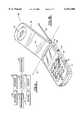
- FIG. 4is an enlarged, fragmented, perspective view of a magnetic object mounted within the housing of a radiotelephone and having a coil wrapped therearound, according to an embodiment of the present invention.
- FIG. 5illustrates an electrical circuit for inducing electrical current flow through a conductive coil, according to the present invention.
- FIG. 6Aillustrates the radiotelephone of FIGS. 3A-3B with the flip cover secured in the closed position via a pair of magnetic objects, according to the present invention.
- FIG. 6Billustrates the radiotelephone of FIGS. 3A-3B wherein the coil has been energized to overcome the mutual attraction of the two magnetic objects so the flip cover can move to an open position.
- FIG. 6Cillustrates the radiotelephone of FIGS. 3A-3B with the flip cover in the open position.
- FIG. 7illustrates another embodiment of the present invention wherein portions of an electronic device housing are joined together magnetically.
- FIG. 8illustrates an electrical circuit for inducing electrical current flow through respective conductive coils to physically separate magnetic objects used to secure together various housing portions of an electronic device, according to the present invention.
- FIG. 9illustrates another embodiment of the present invention wherein a magnetic latch device serves as a vibrator upon receipt of a paging signal.
- a radiotelephone 10 in which the present invention may be incorporatedis illustrated with a "bottom-hinged" flip cover 22.
- the illustrated radiotelephone 10includes a top handset housing 12 and a bottom handset housing 14 connected thereto to form a cavity therein.
- Top and bottom handset housings 12 and 14house a keypad 16 including a plurality of keys 18, a display 20, and electronic components (not shown) that enable the radiotelephone 10 to transmit and receive telecommunications signals.
- a flip cover 22is hinged to the bottom end 13 of the top housing 12, as illustrated.
- the flip cover 22may be pivoted by a user about an axis A between an open position and a closed position.
- the flip cover 22may provide protection to the keypad 16 mounted within the top handset housing 12 from unintentional activation or exposure to the elements.
- the flip cover 22may provide a convenient extension to the radiotelephone 10 and, when fitted with a microphone, may be favorably positioned to receive audio input from a user.
- a radiotelephone 30 in which the present invention may be incorporatedis illustrated with a "top-hinged" flip cover 32.
- the illustrated radiotelephone 30includes a top handset housing 12 and a bottom handset housing 14 connected thereto to form a cavity therein.
- Top and bottom handset housings 12 and 14house a keypad 16 including a plurality of keys 18, a display 20, and electronic components (not shown) that enable the radiotelephone 30 to transmit and receive telecommunications signals.
- a flip cover 32is hinged to the top end 15 of the top housing 12, and is configured to house a speaker 46 therewithin, as illustrated.
- the flip cover 32may be pivoted by a user about an axis A between an open position and a closed position.
- the flip cover 32may provide protection to the keypad 16 mounted within the top handset housing 12 from unintentional activation or exposure to the elements.
- the speaker 46 within the flip cover 32may be favorably positioned to provide audio output to a user.
- FIG. 2A conventional arrangement of electronic components that enable a radiotelephone to transmit and receive telecommunications signals is shown schematically in FIG. 2, and is understood by those skilled in the art of radiotelephone communications.
- An antenna 43 for receiving and transmitting telecommunication signalsis electrically connected to a radio-frequency transceiver 44 that is further electrically connected to a controller 45, such as a microprocessor.
- the controller 45is electrically connected to a speaker 46 that transmits a remote signal from the controller 45 to a user of a radiotelephone.
- the controller 45is also electrically connected to a microphone 47 that receives a voice signal from a user and transmits the voice signal through the controller 45 and transceiver 44 to a remote device.
- the controller 45is electrically connected to a keypad 16 and display 20 that facilitate radiotelephone operation.
- the illustrated radiotelephone 50includes a housing 52 that is configured to enclose electronic components (not shown) that transmit and receive radiotelephone communications signals, and a "top-hinged" flip cover 54 secured to the housing 52 via a hinge assembly 55, as illustrated.
- the flip cover 54is pivotable, relative to the housing 52, between a closed position and an open position. In the closed position (FIG. 3A), the flip cover 54 is in overlying, adjacent relationship with the housing 52, as illustrated. In the open position (FIG. 3B), the flip cover 54 is disposed at an angle, relative to the housing 52, as illustrated.
- a spring member 56is incorporated with the hinge assembly 55 and is configured to exert a biasing force on the flip cover 54 to urge the flip cover 54 to the open position.
- Hinge assemblies for electronic devices, such as radiotelephones, that incorporate springs for exerting a biasing force on a flip cover or other appendageare known to those skilled in this art, and need not be described further herein.
- a first magnet 60ais disposed within the housing 52, and a second magnet 60b is disposed within the flip cover 54 so as to be magnetically attracted to the first magnet 60a when the flip cover 54 is in the closed position (FIG. 3A).
- the first and second magnets 60a, 60bare configured such that a magnetic attraction force therebetween is greater than the biasing force of the spring member 56. Accordingly, the magnetic force between first and second magnets 60a, 60b is sufficient to maintain the flip cover 54 in the closed position against the biasing force of the spring member 56.
- the first and second magnets 60a, 60bare dipole, ferro-electric magnets; however, various types and configurations of magnets may be utilized.
- a single magnet in combination with a magnetic objectsuch as an iron object, can be used.
- magnet 60acould be replaced with a magnetic object.
- another magnetic fieldis generated in the vicinity of the magnetic force between the first and second magnets 60a, 60b.
- the generated magnetic fieldserves as means for reducing the magnetic force between the first and second magnets 60a, 60b, relative to the biasing force of the spring member 56, such that the flip cover 54 is urged to the open position by the spring member 56.
- a magnetic fieldis generated by a magnetic field generator disposed adjacent to one or both of the first and second magnets 60a, 60b.
- a preferred magnetic field generatoris a conductive coil 62 having electric current flowing therethrough to produce a magnetic field.
- a conductive coil 62preferably encircles the first magnet 60a, as illustrated in FIGS. 3A-3B and in the enlarged, fragmented view of FIG. 4.
- the electrical circuit 61is disposed within the radiotelephone housing 52 of FIGS. 3A-3B and is configured to connect the conductive coil 62 with an electrical power source 64.
- the illustrated electrical circuit 61includes a switching element 65 for interrupting flow of electrical current between the electrical power source 64 and the conductive coil 62.
- the power sourceis a direct current (D.C.) power source, such as a battery or a capacitor charged by a battery.
- D.C.direct current
- the switching element 65is controlled by a control device 66 accessible to a user.
- the switching element control device 66extends through a portion of the housing 52 in a location conveniently located for a user. Even more preferably, the switching element control device 66 is in a location that facilitates operation of the switching element control device 66 with the same hand that is holding the radiotelephone 50.
- the electrical circuit 61serves as means for inducing electrical current flow through the conductive coil.
- the illustrated switching element control device 66When a user activates the illustrated switching element control device 66 so as to close the switching element 65, the circuit between the power source 64 and the conductive coil 62 is completed and electrical current can flow through the conductive coil to generate a magnetic field.
- the coil 62is preferably configured such that the generated magnetic field is of sufficient strength to at least partially overcome the mutual attraction of the first and second magnets 60a, 60b.
- FIGS. 6A-6Coperations for opening the flip cover 54 of a radiotelephone 50 incorporating the present invention, is illustrated.
- the flip cover 54is in the closed position. Because the magnetic force between the first and second magnets 60a, 60b is greater than the biasing force of the spring member 56, the flip cover 54 is maintained in the closed position.
- the switching element 65 within the electrical circuit 61is schematically illustrated in the open position. Accordingly, electrical current is prevented from flowing through the conductive coil 62 via the electrical power source 64.
- a userhas activated the switching element 65, thereby closing the electrical circuit 61 and allowing electrical current to flow from the electrical power source 64 into the conductive coil 62.
- the magnetic field generated by the conductive coil 62reduces the magnetic force between the first and second magnets 60a, 60b such that the biasing force of the spring member 56 urges the flip cover 54 towards the open position.
- the flip cover 54is in a fully opened position.
- the switching element 65returns to a position such that the electrical circuit between the electrical power source 64 and the conductive coil 62 is open. Accordingly, upon pivoting the flip cover to the closed position, the first and second magnets 60a, 60b generate an attractive magnetic force therebetween that maintains the flip cover 54 in the closed position.
- the second magnet 60bmay be a magnet associated with the speaker 46 disposed within the flip cover 54.
- the first magnet 60amay be a magnet associated with the speaker 46 disposed within the housing 52.
- the present inventionis not limited to the illustrated embodiment.
- Various electrical circuitsmay serve as means for inducing electrical current flow through a conductive coil.
- the first and second magnets 60a, 60bmay be disposed within the radiotelephone housing 52 and flip cover 54, respectively, in various configurations and positions.
- the present inventionmay be utilized with top-hinged and bottom-hinged flip covers.
- the present inventionmay be utilized with various electronic devices having an appendage that pivots relative to the housing of the electronic device.
- a radiotelephone 70includes a housing 72 having top and bottom housing portions 74, 75.
- the top and bottom housing portions 74, 75are configured to be joined together to enclose electronic components for sending and receiving radiotelephone communications.
- first magnets 76a, 76a'are disposed within the bottom housing portion 75 and second magnets 76b, 76b' are disposed within the top housing portion 74, as illustrated.
- first magnets 77a, 77a'are disposed within the bottom housing portion 75 and second magnets 77b, 77b' are disposed within the top housing portion 74, as illustrated.
- first and second magnets 76a-76b and 77a-77bare positioned along one side 70c of the illustrated radiotelephone 70.
- the respective pairs 76' and 77' of first and second magnets 76a', 76b' and 77a', 77b'are positioned along an opposite side 70d of the illustrated radiotelephone 70.
- the present inventionis not limited to the illustrated arrangement of magnets in FIG. 7.
- Various numbers and configurations of magnetsmay be utilized according to the present invention.
- a single pair of first and second magnetscould be utilized to secure the top and bottom housing portions 74, 75 together.
- a magnet associated with the speaker 46could be utilized as one of the magnets in a respective pair.
- a single magnet in combination with magnetic material, such as ironcould be used.
- the respective illustrated pairs 76, 76', 77, and 77' of magnetsare positioned within the top and bottom housing portions 74, 75 so as to be magnetically attracted to each other when the first and second housing portions 74, 75 are joined together.
- the respective pairs 76, 76', 77, and 77' of magnetsare configured such that the magnetic attraction force therebetween strongly resists forces exerted by a user trying to pull the housing portions apart.
- a magnetic field generatorsuch as a conductive coil, disposed adjacent to at least one of the magnets in each pair.
- conductive coils 78 and 78'encircle respective first magnets 76a and 76a'.
- conductive coils 80 and 80'encircle respective first magnets 77a and 77a'.
- an electrical circuit 61'disposed within the radiotelephone housing 72, for connecting the respective conductive coils 78, 80 with an electrical power source 64, is schematically illustrated.
- the electrical circuit 61'includes a switching element 65 for interrupting flow of electrical current between the electrical power source 64 and the conductive coils 78, 80.
- the power sourceis a direct current (D.C.) power source.
- the switching element 65is controlled by a control device 66 accessible to a user.
- the switching element control device 66is recessed within a port 82 in the housing 72 so as to reduce the likelihood of inadvertent activation.
- the electrical circuit 61'serves as means for inducing electrical current flow through the conductive coils 78, 80.
- each of the coils 78, 80is preferably configured such that the generated magnetic field is of sufficient strength to at least partially overcome the mutual attraction of each the respective magnet pairs 76, 77. Accordingly, a user can then physically separate the top and bottom housing portions 74, 75.
- the illustrated radiotelephone 50includes a housing 52 that is configured to enclose electronic components (not shown) that transmit and receive radiotelephone communications signals, and a "top-hinged", spring-activated flip cover 54 secured to the housing 52 via a hinge assembly (not shown).
- the flip cover 54is pivotable, relative to the housing 52, between a closed position and an open position. In the closed position, the flip cover 54 is in overlying, adjacent relationship with the housing 52, as illustrated.
- a magnet 90is disposed within the flip cover 54, and a magnetic object 92 is disposed within the housing 52 so as to be magnetically attracted to the magnet 90 when the flip cover 54 is in the closed position.
- the magnet 90 and magnetic object 92are configured such that a magnetic attraction force therebetween is greater than the biasing force of a spring member for urging the flip cover 54 to an open position. Accordingly, the magnetic force between the magnet 90 and magnetic object 92 is sufficient to maintain the flip cover 54 in the closed position against the biasing force of a spring member.
- the magnetic object 92is formed from iron or other materials containing iron.
- air gaps 93 and 94 between the magnet 90 and the magnetic object 92 when the flip cover 54 is in the closed positionare preferably very small.
- the flux densitycan be maximized which maximizes the magnetic attraction between the magnet 90 and magnetic object 92.
- flux leakage into other areas within the radiotelephonecan be reduced or prevented altogether. Even more preferably, no air gaps exist.
- the magnetic object 92has a "U-shaped" configuration, as illustrated.
- a conductive coil 62encircles the magnetic object 92 and is configured to produce a magnetic field when a pulse of electric current flows therethrough.
- the generated magnetic fieldserves as means for reducing the magnetic force between the magnet 90 and magnetic object 92 relative to the biasing force of the spring member, such that the flip cover 54 is urged to the open position by the spring member.
- the direction of the electric current and the direction of the winding of the coil 62are such that the magnetic flux generated opposes the magnetic flux of the magnet 90. If the opposing magnetic flux is equal to the magnetic flux of the magnet 90, the flip cover 54 will release and move to the open position. If the opposing magnetic flux exceeds the magnetic flux of the magnet 90, the flip cover 54 will be accelerated to the open position.
- Electric currentmay be provided to the coil 62 via a D.C. power source, such as a battery 95. In the illustrated embodiment, the battery 95 charges a capacitor 96. Electric current is taken from the capacitor 96 to relieve the battery 95 of a heavy electric current pulse.
- magnet 90 and magnetic object 92may also serve as a vibrator as an indicator of an incoming call.
- a time-varying voltagemay be supplied from a time-varying voltage generator 97 to the coil 62 when a page signal is received. Time-varying voltage generators are understood by those skilled in this art and need not be described further herein.
- the supplied voltagecauses the flip cover 54 to vibrate as the magnetic force between the magnet 90 and magnetic object 92 varies with the time-varying voltage.
- the time-varying voltagemay be pulsed in resonance with a resonant frequency (also referred to as a natural frequency) of the radiotelephone/flip cover system, generating much larger flip cover displacements than if some other "off resonance" frequency were used.
- the magnet 90may be disposed within the flip cover 54 so as to have some freedom of movement. Accordingly, the magnet 90 could vibrate upon receipt of a paging signal.
Landscapes
- Engineering & Computer Science (AREA)
- Signal Processing (AREA)
- Telephone Set Structure (AREA)
Abstract
Description
Claims (45)
Priority Applications (1)
| Application Number | Priority Date | Filing Date | Title |
|---|---|---|---|
| US09/182,682US6151486A (en) | 1998-10-30 | 1998-10-30 | Magnetic latch and release device and radiotelephones incorporating same |
Applications Claiming Priority (1)
| Application Number | Priority Date | Filing Date | Title |
|---|---|---|---|
| US09/182,682US6151486A (en) | 1998-10-30 | 1998-10-30 | Magnetic latch and release device and radiotelephones incorporating same |
Publications (1)
| Publication Number | Publication Date |
|---|---|
| US6151486Atrue US6151486A (en) | 2000-11-21 |
Family
ID=22669561
Family Applications (1)
| Application Number | Title | Priority Date | Filing Date |
|---|---|---|---|
| US09/182,682Expired - LifetimeUS6151486A (en) | 1998-10-30 | 1998-10-30 | Magnetic latch and release device and radiotelephones incorporating same |
Country Status (1)
| Country | Link |
|---|---|
| US (1) | US6151486A (en) |
Cited By (77)
| Publication number | Priority date | Publication date | Assignee | Title |
|---|---|---|---|---|
| US20010009847A1 (en)* | 2000-01-24 | 2001-07-26 | Lg Electronics Inc. | Drawer-type mobile phone |
| US6304765B1 (en)* | 1999-11-16 | 2001-10-16 | Motorola, Inc. | Foldable communication device and method |
| US6324386B1 (en)* | 1998-03-19 | 2001-11-27 | Samsung Electronics Co., Ltd. | Folding communication device |
| US20020022496A1 (en)* | 2000-08-08 | 2002-02-21 | Lg Electronics Inc. | Flip type mobile telephone |
| US6363243B1 (en)* | 1998-04-07 | 2002-03-26 | Telefonaktiebolaget L M Ericsson | Arrangement relating to mechanically interlocking devices |
| US6389302B1 (en)* | 1999-04-28 | 2002-05-14 | Ericsson Inc. | Methods and apparatus for causing wireless communication devices to vibrate via piezo-ceramic vibrators |
| US20020061733A1 (en)* | 2000-11-21 | 2002-05-23 | Zijie Wang | Unfolding apparatus for foldable electronic device |
| US20020068614A1 (en)* | 2000-12-04 | 2002-06-06 | International Business Machines Corporation | Personal communication device having a built in projection display |
| US6459887B2 (en)* | 2000-03-03 | 2002-10-01 | Sanyo Electric Co., Ltd. | Foldable portable telephone |
| US20020147026A1 (en)* | 2001-04-04 | 2002-10-10 | Yung-Tsun Hsieh | Magnetic hinge apparatus |
| US6594472B1 (en)* | 1999-02-12 | 2003-07-15 | Nokia Mobile Phones Ltd. | Exchangeable radiotelephone covers |
| US6630878B2 (en)* | 2002-03-08 | 2003-10-07 | Benq Corporation | Magnetic rotating apparatus |
| GB2388487A (en)* | 2002-01-09 | 2003-11-12 | Nec Technologies | Folding mobile phone with magnetically actuated catch |
| US20040114754A1 (en)* | 2000-12-29 | 2004-06-17 | Frank Nuovo | Device with a loudspeaker and an ear piece cover |
| US6763110B1 (en)* | 1998-12-18 | 2004-07-13 | Lg Information & Communications, Ltd. | Sound guide for speaker and handset for mobile communication using the same |
| KR100442625B1 (en)* | 2002-04-11 | 2004-08-02 | 삼성전자주식회사 | Apparatus and method for controlling the malfunction of hall effect switch used for sensing open or close of the flip or polder of terminal equipment |
| US20040198245A1 (en)* | 2002-09-17 | 2004-10-07 | Chow Tatt Hoong | Latch mechanism and electronic device employing a latch mechanism |
| US20050014526A1 (en)* | 2003-07-15 | 2005-01-20 | Long-Jyh Pan | Method for identifying a detachable cover of a portable communications device |
| US20050018869A1 (en)* | 2002-10-25 | 2005-01-27 | Kenichi Ajiki | Electroacoustic transducer and process for producing the same |
| US20050167992A1 (en)* | 2004-01-29 | 2005-08-04 | Chien-Sheng Lo | Electronic apparatus having magnetic switch |
| US6961593B1 (en)* | 1998-03-18 | 2005-11-01 | Nokia Mobile Phones, Ltd | Telescopic telephone |
| US20060046792A1 (en)* | 2004-08-31 | 2006-03-02 | Hassemer Brian J | Hinge apparatus and methods therefor |
| US20060050867A1 (en)* | 2002-09-26 | 2006-03-09 | Masanobu Kawamoto | Electronic apparatus and its openning closing mechanism |
| US20060071746A1 (en)* | 2004-10-04 | 2006-04-06 | Nokia Corporation | Vibration and locking system |
| EP1422912A3 (en)* | 2002-11-20 | 2006-10-25 | Nec Corporation | Mobile terminal , orientation and open/close detection method thereof |
| US20070133156A1 (en)* | 2005-12-13 | 2007-06-14 | Chris Ligtenberg | Electronic device having magnetic latching mechanism |
| US20070138806A1 (en)* | 2005-12-13 | 2007-06-21 | Apple Computer, Inc. | Magnetic latching mechanism |
| USD567210S1 (en)* | 2005-03-23 | 2008-04-22 | Nokia Corporation | Handset body |
| US20080121053A1 (en)* | 2006-11-27 | 2008-05-29 | Nokia Corporation | Opening system |
| US20080186683A1 (en)* | 2006-10-16 | 2008-08-07 | Ligtenberg Chris A | Magnetic latch mechanism |
| US20080232071A1 (en)* | 2007-03-19 | 2008-09-25 | Schechtel Kevin J | Hinged Device with Rotational Hinge Actuation |
| US7551429B1 (en)* | 2001-11-21 | 2009-06-23 | Palm, Inc. | Multifunctional cover integrated into sub-panel of portable electronic device |
| US20090284473A1 (en)* | 2008-05-15 | 2009-11-19 | Yu-Chang Huang | Handheld type electronic device |
| WO2009156555A1 (en)* | 2008-06-27 | 2009-12-30 | Nokia Corporation | Apparatus, add-on module, and a system comprising a host apparatus and an add-on module |
| US20100124698A1 (en)* | 2008-11-19 | 2010-05-20 | Shenzhen Futaihong Precision Industry Co., Ltd. | Battery cover assembly for portable electronic device |
| CN101771737A (en)* | 2009-01-05 | 2010-07-07 | 深圳富泰宏精密工业有限公司 | Electronic device |
| US20100299902A1 (en)* | 2009-05-26 | 2010-12-02 | Nokia Corporation | Method and apparatus for joining two parts |
| US20100331059A1 (en)* | 2009-06-30 | 2010-12-30 | Jeffrey Apgar | Apparatus with swivel hinge and associated method |
| US20110007466A1 (en)* | 2009-07-10 | 2011-01-13 | Hong Fu Jin Precision Industry (Shenzhen) Co., Ltd. | Support mechanism and electronic device using the same |
| US7876550B1 (en) | 2003-02-27 | 2011-01-25 | Palm, Inc. | Transparent cover with access to multi-way navigation assembly |
| US20110043970A1 (en)* | 2009-08-20 | 2011-02-24 | Nokia Corporation | Rotational apparatus for communication |
| US8143982B1 (en) | 2010-09-17 | 2012-03-27 | Apple Inc. | Foldable accessory device |
| US8143983B1 (en) | 2010-09-17 | 2012-03-27 | Apple Inc. | Electronic device with magnetic attachment |
| WO2012057952A3 (en)* | 2010-10-26 | 2012-06-14 | Barnes & Noble, Inc | A door mechanism for secure digital memory card |
| US8253518B2 (en) | 2010-09-17 | 2012-08-28 | Apple Inc. | Foldable cover for electronic device |
| US8264310B2 (en) | 2010-09-17 | 2012-09-11 | Apple Inc. | Accessory device for peek mode |
| US20120257397A1 (en)* | 2011-04-08 | 2012-10-11 | Samsung Mobile Display Co., Ltd. | Organic light emitting diode lighting apparatus |
| US8289115B2 (en) | 2010-09-17 | 2012-10-16 | Apple Inc. | Sensor fusion |
| US20120287595A1 (en)* | 2011-05-09 | 2012-11-15 | Wistron Corporation | Electronic Device and Fixing Structure Therefor |
| US20120327580A1 (en)* | 2011-06-23 | 2012-12-27 | Zagg Intellectual Property Holding Co., Inc. | Protective devices and systems for portable electronic devices and associated methods |
| US8344836B2 (en) | 2010-09-17 | 2013-01-01 | Apple Inc. | Protective cover for a tablet computer |
| US8390411B2 (en) | 2010-09-17 | 2013-03-05 | Apple Inc. | Tablet device |
| US8395465B2 (en) | 2010-09-17 | 2013-03-12 | Apple Inc. | Cover for an electric device |
| US8514042B2 (en) | 2010-09-17 | 2013-08-20 | Apple Inc. | Magnetic attachment system |
| US20130269261A1 (en)* | 2011-03-24 | 2013-10-17 | Correlated Magnetics Research, Llc. | Detachable Cover System |
| US8587396B2 (en)* | 2011-05-09 | 2013-11-19 | Wistron Corporation | Electronic device and retaining mechanism for retaining a magnetic element of the electronic device |
| US20140092535A1 (en)* | 2012-09-29 | 2014-04-03 | Hon Hai Precision Industry Co., Ltd. | Sliding mechanism and electronic apparatus having same |
| US20140265781A1 (en)* | 2013-03-15 | 2014-09-18 | Adt Us Holdings, Inc. | Panel with magnetic hinge |
| US20140347813A1 (en)* | 2013-05-23 | 2014-11-27 | Pegatron Corporation | Electronic device opened by magnetic force |
| US20150070119A1 (en)* | 2012-08-20 | 2015-03-12 | Microsoft Corporation | Switchable Magnetic Lock |
| TWI483142B (en)* | 2009-07-15 | 2015-05-01 | Hon Hai Prec Ind Co Ltd | Support mechanism and electronic device using the same |
| TWI489849B (en)* | 2009-01-16 | 2015-06-21 | 奇美通訊股份有限公司 | Electronic device |
| US20150262746A1 (en)* | 2014-03-14 | 2015-09-17 | Apple Inc. | Method and apparatus for producing accurate kinematics in a computing device |
| US9218024B2 (en) | 2011-06-23 | 2015-12-22 | Zagg Intellectual Property Holding Co., Inc. | Accessory and support for electronic devices, systems including the same and methods |
| CN105245647A (en)* | 2015-10-09 | 2016-01-13 | 小米科技有限责任公司 | Card slot automatic ejection device and electronic equipment |
| US20160031516A1 (en)* | 2014-08-01 | 2016-02-04 | Ford Global Technologies, Llc | Electric bicycle |
| US9678542B2 (en) | 2012-03-02 | 2017-06-13 | Microsoft Technology Licensing, Llc | Multiple position input device cover |
| US9706089B2 (en) | 2012-03-02 | 2017-07-11 | Microsoft Technology Licensing, Llc | Shifted lens camera for mobile computing devices |
| US9766663B2 (en) | 2012-03-02 | 2017-09-19 | Microsoft Technology Licensing, Llc | Hinge for component attachment |
| US20180162282A1 (en)* | 2016-05-18 | 2018-06-14 | Shanghai Yanfeng Jinqiao Automotive Trim Systems Co. Ltd. | Console assembly for vehicle interior |
| US10120420B2 (en) | 2014-03-21 | 2018-11-06 | Microsoft Technology Licensing, Llc | Lockable display and techniques enabling use of lockable displays |
| CN109429453A (en)* | 2017-08-22 | 2019-03-05 | 三星电子株式会社 | Electronic device and box device with the opening/closing structure using magnetic force |
| US10324733B2 (en) | 2014-07-30 | 2019-06-18 | Microsoft Technology Licensing, Llc | Shutdown notifications |
| US11134580B2 (en) | 2010-07-08 | 2021-09-28 | Zagg Inc | Protective cover for portable electronic device and associated systems and methods |
| US11147171B2 (en)* | 2020-02-05 | 2021-10-12 | Lg Electronics Inc. | Electronic apparatus including flexible display |
| US11572723B2 (en) | 2019-02-27 | 2023-02-07 | Shanghai Yanfeng Jinqiao Automotive Triim Systems Co. Ltd. | Vehicle interior component |
| US11886253B1 (en)* | 2018-09-07 | 2024-01-30 | Apple Inc. | Magnetic field adjustments to a magnetic latch for producing accurate kinematics in a computing device |
Citations (5)
| Publication number | Priority date | Publication date | Assignee | Title |
|---|---|---|---|---|
| US5493690A (en)* | 1993-06-28 | 1996-02-20 | Nec Corporation | Foldable portable telephone set |
| US5566362A (en)* | 1994-05-03 | 1996-10-15 | Audiopack Sound Systems, Inc. | Wireless voice transmission system |
| US5659888A (en)* | 1992-05-01 | 1997-08-19 | Kabushiki Kaisha Toshiba | Radio telecommunication apparatus |
| US5706332A (en)* | 1994-09-22 | 1998-01-06 | Nec Corporation | Apparatus for unfolding and activating a portable telephone |
| US5857157A (en)* | 1995-06-06 | 1999-01-05 | Sony Corporation | Portable communication terminal apparatus |
- 1998
- 1998-10-30USUS09/182,682patent/US6151486A/ennot_activeExpired - Lifetime
Patent Citations (5)
| Publication number | Priority date | Publication date | Assignee | Title |
|---|---|---|---|---|
| US5659888A (en)* | 1992-05-01 | 1997-08-19 | Kabushiki Kaisha Toshiba | Radio telecommunication apparatus |
| US5493690A (en)* | 1993-06-28 | 1996-02-20 | Nec Corporation | Foldable portable telephone set |
| US5566362A (en)* | 1994-05-03 | 1996-10-15 | Audiopack Sound Systems, Inc. | Wireless voice transmission system |
| US5706332A (en)* | 1994-09-22 | 1998-01-06 | Nec Corporation | Apparatus for unfolding and activating a portable telephone |
| US5857157A (en)* | 1995-06-06 | 1999-01-05 | Sony Corporation | Portable communication terminal apparatus |
Cited By (136)
| Publication number | Priority date | Publication date | Assignee | Title |
|---|---|---|---|---|
| US6961593B1 (en)* | 1998-03-18 | 2005-11-01 | Nokia Mobile Phones, Ltd | Telescopic telephone |
| US7519404B2 (en) | 1998-03-18 | 2009-04-14 | Nokia Corporation | Telescopic telephone |
| US20050265545A1 (en)* | 1998-03-18 | 2005-12-01 | Pekka Lonka | Telescopic telephone |
| US6324386B1 (en)* | 1998-03-19 | 2001-11-27 | Samsung Electronics Co., Ltd. | Folding communication device |
| US6363243B1 (en)* | 1998-04-07 | 2002-03-26 | Telefonaktiebolaget L M Ericsson | Arrangement relating to mechanically interlocking devices |
| US20070049359A1 (en)* | 1998-12-18 | 2007-03-01 | Lg Electronics Inc. | Sound guide for speaker and handset for mobile communication using the same |
| US7139395B2 (en) | 1998-12-18 | 2006-11-21 | Lg Electronics Inc. | Sound guide for speaker and handset for mobile communication using the same |
| US20040170272A1 (en)* | 1998-12-18 | 2004-09-02 | Lg Information & Communications, Ltd. | Sound guide for speaker and handset for mobile communication using the same |
| US6763110B1 (en)* | 1998-12-18 | 2004-07-13 | Lg Information & Communications, Ltd. | Sound guide for speaker and handset for mobile communication using the same |
| US7627112B2 (en) | 1998-12-18 | 2009-12-01 | Lg Electronics Inc. | Sound guide for speaker and handset for mobile communication using the same |
| US6594472B1 (en)* | 1999-02-12 | 2003-07-15 | Nokia Mobile Phones Ltd. | Exchangeable radiotelephone covers |
| US20030194974A1 (en)* | 1999-02-12 | 2003-10-16 | Curtis Alastair S. | Radiotelephone |
| US6847806B2 (en)* | 1999-02-12 | 2005-01-25 | Nokia Mobile Phones Ltd. | Radiotelephone |
| US6389302B1 (en)* | 1999-04-28 | 2002-05-14 | Ericsson Inc. | Methods and apparatus for causing wireless communication devices to vibrate via piezo-ceramic vibrators |
| US6304765B1 (en)* | 1999-11-16 | 2001-10-16 | Motorola, Inc. | Foldable communication device and method |
| US20010009847A1 (en)* | 2000-01-24 | 2001-07-26 | Lg Electronics Inc. | Drawer-type mobile phone |
| US6980840B2 (en)* | 2000-01-24 | 2005-12-27 | Lg Electronics Inc. | Drawer-type mobile phone |
| US20060079301A1 (en)* | 2000-01-24 | 2006-04-13 | Lg Electronics Inc. | Drawer-type mobile phone |
| US7245949B2 (en) | 2000-01-24 | 2007-07-17 | Lg Electronics, Inc. | Drawer-type mobile phone |
| US6459887B2 (en)* | 2000-03-03 | 2002-10-01 | Sanyo Electric Co., Ltd. | Foldable portable telephone |
| US20020022496A1 (en)* | 2000-08-08 | 2002-02-21 | Lg Electronics Inc. | Flip type mobile telephone |
| US20020061733A1 (en)* | 2000-11-21 | 2002-05-23 | Zijie Wang | Unfolding apparatus for foldable electronic device |
| US20020068614A1 (en)* | 2000-12-04 | 2002-06-06 | International Business Machines Corporation | Personal communication device having a built in projection display |
| US7184796B2 (en)* | 2000-12-04 | 2007-02-27 | International Business Machines Corporation | Personal communication device having a built in projection display |
| US7454014B2 (en)* | 2000-12-29 | 2008-11-18 | Vertu Limited | Device with a loudspeaker and an ear piece cover |
| US20040114754A1 (en)* | 2000-12-29 | 2004-06-17 | Frank Nuovo | Device with a loudspeaker and an ear piece cover |
| US6832100B2 (en)* | 2001-04-04 | 2004-12-14 | Benq Corporation | Magnetic hinge apparatus |
| US20020147026A1 (en)* | 2001-04-04 | 2002-10-10 | Yung-Tsun Hsieh | Magnetic hinge apparatus |
| US7551429B1 (en)* | 2001-11-21 | 2009-06-23 | Palm, Inc. | Multifunctional cover integrated into sub-panel of portable electronic device |
| US8270149B2 (en) | 2001-11-21 | 2012-09-18 | Hewlett-Packard Development Company, L.P. | Multifunctional cover integrated into sub-panel of portable electronic device |
| US20090268402A1 (en)* | 2001-11-21 | 2009-10-29 | William Robert Hanson | Multifunctional cover integrated into sub-panel of portable electronic device |
| GB2388487A (en)* | 2002-01-09 | 2003-11-12 | Nec Technologies | Folding mobile phone with magnetically actuated catch |
| GB2388487B (en)* | 2002-01-09 | 2005-11-09 | Nec Technologies | Method of opening folding mobile equipment |
| US6630878B2 (en)* | 2002-03-08 | 2003-10-07 | Benq Corporation | Magnetic rotating apparatus |
| KR100442625B1 (en)* | 2002-04-11 | 2004-08-02 | 삼성전자주식회사 | Apparatus and method for controlling the malfunction of hall effect switch used for sensing open or close of the flip or polder of terminal equipment |
| US20040198245A1 (en)* | 2002-09-17 | 2004-10-07 | Chow Tatt Hoong | Latch mechanism and electronic device employing a latch mechanism |
| US7003333B2 (en) | 2002-09-17 | 2006-02-21 | Motorola, Inc. | Latch mechanism and electronic device employing a latch mechanism |
| US20060050867A1 (en)* | 2002-09-26 | 2006-03-09 | Masanobu Kawamoto | Electronic apparatus and its openning closing mechanism |
| US20050018869A1 (en)* | 2002-10-25 | 2005-01-27 | Kenichi Ajiki | Electroacoustic transducer and process for producing the same |
| US7316289B2 (en)* | 2002-10-25 | 2008-01-08 | Matsushita Electric Industrial Co., Ltd. | Electro-acoustic transducer and method of manufacturing transducer |
| EP1422912A3 (en)* | 2002-11-20 | 2006-10-25 | Nec Corporation | Mobile terminal , orientation and open/close detection method thereof |
| US7876550B1 (en) | 2003-02-27 | 2011-01-25 | Palm, Inc. | Transparent cover with access to multi-way navigation assembly |
| US20050014526A1 (en)* | 2003-07-15 | 2005-01-20 | Long-Jyh Pan | Method for identifying a detachable cover of a portable communications device |
| US7332990B2 (en)* | 2004-01-29 | 2008-02-19 | Asustek Computer Inc. | Portable computer |
| US20050167992A1 (en)* | 2004-01-29 | 2005-08-04 | Chien-Sheng Lo | Electronic apparatus having magnetic switch |
| US20060046792A1 (en)* | 2004-08-31 | 2006-03-02 | Hassemer Brian J | Hinge apparatus and methods therefor |
| US20060071746A1 (en)* | 2004-10-04 | 2006-04-06 | Nokia Corporation | Vibration and locking system |
| USD567210S1 (en)* | 2005-03-23 | 2008-04-22 | Nokia Corporation | Handset body |
| US20070133156A1 (en)* | 2005-12-13 | 2007-06-14 | Chris Ligtenberg | Electronic device having magnetic latching mechanism |
| US7583500B2 (en) | 2005-12-13 | 2009-09-01 | Apple Inc. | Electronic device having magnetic latching mechanism |
| US20110026203A1 (en)* | 2005-12-13 | 2011-02-03 | Chris Ligtenberg | Electronic device and magnetic latching mechanism therefore |
| US20070138806A1 (en)* | 2005-12-13 | 2007-06-21 | Apple Computer, Inc. | Magnetic latching mechanism |
| US8801054B2 (en) | 2005-12-13 | 2014-08-12 | Apple Inc. | Electronic device and magnetic latching mechanism therefor |
| US7775567B2 (en) | 2005-12-13 | 2010-08-17 | Apple Inc. | Magnetic latching mechanism |
| US20080186683A1 (en)* | 2006-10-16 | 2008-08-07 | Ligtenberg Chris A | Magnetic latch mechanism |
| US7486165B2 (en)* | 2006-10-16 | 2009-02-03 | Apple Inc. | Magnetic latch mechanism |
| US20080121053A1 (en)* | 2006-11-27 | 2008-05-29 | Nokia Corporation | Opening system |
| US20080232071A1 (en)* | 2007-03-19 | 2008-09-25 | Schechtel Kevin J | Hinged Device with Rotational Hinge Actuation |
| US8031461B2 (en)* | 2007-03-19 | 2011-10-04 | Motorola Mobility, Inc. | Hinged device with rotational hinge actuation |
| US20090284473A1 (en)* | 2008-05-15 | 2009-11-19 | Yu-Chang Huang | Handheld type electronic device |
| US8346321B2 (en)* | 2008-05-15 | 2013-01-01 | Wistron Corporation | Handheld type electronic device |
| US8817476B2 (en) | 2008-06-27 | 2014-08-26 | Nokia Corporation | Apparatus, add-on module, and a system comprising a host apparatus and an add-on module |
| WO2009156555A1 (en)* | 2008-06-27 | 2009-12-30 | Nokia Corporation | Apparatus, add-on module, and a system comprising a host apparatus and an add-on module |
| US20100124698A1 (en)* | 2008-11-19 | 2010-05-20 | Shenzhen Futaihong Precision Industry Co., Ltd. | Battery cover assembly for portable electronic device |
| US8078238B2 (en)* | 2009-01-05 | 2011-12-13 | Shenzhen Futaihong Precision Industry Co., Ltd. | Electronic device |
| CN101771737A (en)* | 2009-01-05 | 2010-07-07 | 深圳富泰宏精密工业有限公司 | Electronic device |
| US20100173676A1 (en)* | 2009-01-05 | 2010-07-08 | Shenzhen Futaihong Precision Industry Co., Ltd. | Electronic device |
| TWI489849B (en)* | 2009-01-16 | 2015-06-21 | 奇美通訊股份有限公司 | Electronic device |
| US20100299902A1 (en)* | 2009-05-26 | 2010-12-02 | Nokia Corporation | Method and apparatus for joining two parts |
| WO2011001013A1 (en)* | 2009-06-30 | 2011-01-06 | Nokia Corporation | Apparatus with swivel hinge and associated method |
| US20100331059A1 (en)* | 2009-06-30 | 2010-12-30 | Jeffrey Apgar | Apparatus with swivel hinge and associated method |
| US7986525B2 (en)* | 2009-07-10 | 2011-07-26 | Hong Fu Jin Precision Industry (Shenzhen) Co., Ltd. | Support mechanism and electronic device using the same |
| US20110007466A1 (en)* | 2009-07-10 | 2011-01-13 | Hong Fu Jin Precision Industry (Shenzhen) Co., Ltd. | Support mechanism and electronic device using the same |
| TWI483142B (en)* | 2009-07-15 | 2015-05-01 | Hon Hai Prec Ind Co Ltd | Support mechanism and electronic device using the same |
| US20110043970A1 (en)* | 2009-08-20 | 2011-02-24 | Nokia Corporation | Rotational apparatus for communication |
| US8199493B2 (en)* | 2009-08-20 | 2012-06-12 | Nokia Corporation | Rotational apparatus for communication |
| US11134580B2 (en) | 2010-07-08 | 2021-09-28 | Zagg Inc | Protective cover for portable electronic device and associated systems and methods |
| US9329630B2 (en) | 2010-09-17 | 2016-05-03 | Apple Inc. | Cover |
| US8514042B2 (en) | 2010-09-17 | 2013-08-20 | Apple Inc. | Magnetic attachment system |
| US9568954B2 (en) | 2010-09-17 | 2017-02-14 | Apple Inc. | Cover for an electronic device |
| US9773598B2 (en) | 2010-09-17 | 2017-09-26 | Apple Inc. | Cover for an electronic device |
| US8344836B2 (en) | 2010-09-17 | 2013-01-01 | Apple Inc. | Protective cover for a tablet computer |
| US8264310B2 (en) | 2010-09-17 | 2012-09-11 | Apple Inc. | Accessory device for peek mode |
| US8390411B2 (en) | 2010-09-17 | 2013-03-05 | Apple Inc. | Tablet device |
| US8390412B2 (en) | 2010-09-17 | 2013-03-05 | Apple Inc. | Protective cover |
| US8395465B2 (en) | 2010-09-17 | 2013-03-12 | Apple Inc. | Cover for an electric device |
| US8289115B2 (en) | 2010-09-17 | 2012-10-16 | Apple Inc. | Sensor fusion |
| US10236106B2 (en) | 2010-09-17 | 2019-03-19 | Apple Inc. | Cover for an electronic device |
| US8576031B2 (en) | 2010-09-17 | 2013-11-05 | Apple Inc. | Consumer product system |
| US10580556B2 (en) | 2010-09-17 | 2020-03-03 | Apple Inc. | Cover for an electronic device |
| US8253518B2 (en) | 2010-09-17 | 2012-08-28 | Apple Inc. | Foldable cover for electronic device |
| US8143982B1 (en) | 2010-09-17 | 2012-03-27 | Apple Inc. | Foldable accessory device |
| EP2431836A3 (en)* | 2010-09-17 | 2012-05-02 | Apple Inc. | Electronic device with magnetic attachment |
| US8143983B1 (en) | 2010-09-17 | 2012-03-27 | Apple Inc. | Electronic device with magnetic attachment |
| WO2012057952A3 (en)* | 2010-10-26 | 2012-06-14 | Barnes & Noble, Inc | A door mechanism for secure digital memory card |
| US20130269261A1 (en)* | 2011-03-24 | 2013-10-17 | Correlated Magnetics Research, Llc. | Detachable Cover System |
| US8841981B2 (en)* | 2011-03-24 | 2014-09-23 | Correlated Magnetics Research, Llc. | Detachable cover system |
| US8783935B2 (en)* | 2011-04-08 | 2014-07-22 | Samsung Display Co., Ltd. | Organic light emitting diode lighting apparatus |
| US20120257397A1 (en)* | 2011-04-08 | 2012-10-11 | Samsung Mobile Display Co., Ltd. | Organic light emitting diode lighting apparatus |
| US20120287595A1 (en)* | 2011-05-09 | 2012-11-15 | Wistron Corporation | Electronic Device and Fixing Structure Therefor |
| US8749971B2 (en)* | 2011-05-09 | 2014-06-10 | Wistron Corporation | Electronic device and fixing structure therefor |
| US8587396B2 (en)* | 2011-05-09 | 2013-11-19 | Wistron Corporation | Electronic device and retaining mechanism for retaining a magnetic element of the electronic device |
| US11353963B2 (en) | 2011-06-23 | 2022-06-07 | Zagg Inc | Accessory and support for electronic devices, systems including the same and methods |
| US9218024B2 (en) | 2011-06-23 | 2015-12-22 | Zagg Intellectual Property Holding Co., Inc. | Accessory and support for electronic devices, systems including the same and methods |
| US10013074B2 (en) | 2011-06-23 | 2018-07-03 | Zagg Intellectual Property Holding Co., Inc. | Accessory and support for electronic devices, systems including the same and methods |
| US20120327580A1 (en)* | 2011-06-23 | 2012-12-27 | Zagg Intellectual Property Holding Co., Inc. | Protective devices and systems for portable electronic devices and associated methods |
| US10599229B2 (en) | 2011-06-23 | 2020-03-24 | Zagg Intellectual Property Holding Co., Inc. | Accessory and support for electronic devices, systems including the same and methods |
| US9706089B2 (en) | 2012-03-02 | 2017-07-11 | Microsoft Technology Licensing, Llc | Shifted lens camera for mobile computing devices |
| US10013030B2 (en) | 2012-03-02 | 2018-07-03 | Microsoft Technology Licensing, Llc | Multiple position input device cover |
| US9766663B2 (en) | 2012-03-02 | 2017-09-19 | Microsoft Technology Licensing, Llc | Hinge for component attachment |
| US10963087B2 (en) | 2012-03-02 | 2021-03-30 | Microsoft Technology Licensing, Llc | Pressure sensitive keys |
| US9678542B2 (en) | 2012-03-02 | 2017-06-13 | Microsoft Technology Licensing, Llc | Multiple position input device cover |
| US20150070119A1 (en)* | 2012-08-20 | 2015-03-12 | Microsoft Corporation | Switchable Magnetic Lock |
| US9824808B2 (en)* | 2012-08-20 | 2017-11-21 | Microsoft Technology Licensing, Llc | Switchable magnetic lock |
| US9101052B2 (en)* | 2012-09-29 | 2015-08-04 | Fu Tai Hua Industry (Shenzhen) Co., Ltd. | Sliding mechanism and electronic apparatus having same |
| US20140092535A1 (en)* | 2012-09-29 | 2014-04-03 | Hon Hai Precision Industry Co., Ltd. | Sliding mechanism and electronic apparatus having same |
| US20140265781A1 (en)* | 2013-03-15 | 2014-09-18 | Adt Us Holdings, Inc. | Panel with magnetic hinge |
| US20140347813A1 (en)* | 2013-05-23 | 2014-11-27 | Pegatron Corporation | Electronic device opened by magnetic force |
| US9332663B2 (en)* | 2013-05-23 | 2016-05-03 | Maintek Computer (Suzhou) Co., Ltd | Electronic device opened by magnetic force |
| CN104181981A (en)* | 2013-05-23 | 2014-12-03 | 名硕电脑(苏州)有限公司 | Electronic device capable of being opened by utilizing magnetic force |
| US9214268B2 (en)* | 2014-03-14 | 2015-12-15 | Apple Inc. | Method and apparatus for producing accurate kinematics in a computing device |
| US20150262746A1 (en)* | 2014-03-14 | 2015-09-17 | Apple Inc. | Method and apparatus for producing accurate kinematics in a computing device |
| US10120420B2 (en) | 2014-03-21 | 2018-11-06 | Microsoft Technology Licensing, Llc | Lockable display and techniques enabling use of lockable displays |
| US10324733B2 (en) | 2014-07-30 | 2019-06-18 | Microsoft Technology Licensing, Llc | Shutdown notifications |
| US20160031516A1 (en)* | 2014-08-01 | 2016-02-04 | Ford Global Technologies, Llc | Electric bicycle |
| US9701356B2 (en)* | 2014-08-01 | 2017-07-11 | Ford Global Technologies, Llc | Electric bicycle |
| US10202161B2 (en) | 2014-08-01 | 2019-02-12 | Ford Global Technologies, Llc | Electric bicycle |
| RU2684825C2 (en)* | 2014-08-01 | 2019-04-15 | ФОРД ГЛОУБАЛ ТЕКНОЛОДЖИЗ, ЭлЭлСи | Electric bicycle |
| CN105245647A (en)* | 2015-10-09 | 2016-01-13 | 小米科技有限责任公司 | Card slot automatic ejection device and electronic equipment |
| US10737628B2 (en)* | 2016-05-18 | 2020-08-11 | Shanghai Yanfeng Jinqiao Automotive Trim Systems Co. Ltd. | Console assembly for vehicle interior |
| US10717390B2 (en) | 2016-05-18 | 2020-07-21 | Shanghai Yanfeng Jinqiao Automotive Trim Systems Co. Ltd. | Console assembly for vehicle interior |
| US20180162282A1 (en)* | 2016-05-18 | 2018-06-14 | Shanghai Yanfeng Jinqiao Automotive Trim Systems Co. Ltd. | Console assembly for vehicle interior |
| CN109429453A (en)* | 2017-08-22 | 2019-03-05 | 三星电子株式会社 | Electronic device and box device with the opening/closing structure using magnetic force |
| US11886253B1 (en)* | 2018-09-07 | 2024-01-30 | Apple Inc. | Magnetic field adjustments to a magnetic latch for producing accurate kinematics in a computing device |
| US11572723B2 (en) | 2019-02-27 | 2023-02-07 | Shanghai Yanfeng Jinqiao Automotive Triim Systems Co. Ltd. | Vehicle interior component |
| US11147171B2 (en)* | 2020-02-05 | 2021-10-12 | Lg Electronics Inc. | Electronic apparatus including flexible display |
Similar Documents
| Publication | Publication Date | Title |
|---|---|---|
| US6151486A (en) | Magnetic latch and release device and radiotelephones incorporating same | |
| EP4096235A1 (en) | Electronic device for storing external electronic device | |
| US6980840B2 (en) | Drawer-type mobile phone | |
| KR100678082B1 (en) | Connection between main board and LCD module in folder type mobile phone | |
| US6288519B1 (en) | Charging and vibrating method using movable magnets for a product using rechargeable batteries | |
| US6782273B2 (en) | Portable wireless apparatus | |
| KR100969747B1 (en) | Portable wireless terminal with ground connecting device using hinge device | |
| EP1292042A2 (en) | Foldable portable phone with metal casing, shieldings and second antenna to control radiation | |
| US5673314A (en) | Electronic device with door cover speaker actuator and latch mechanism | |
| KR20080069819A (en) | Switchgear of cell phone | |
| EP1000524B1 (en) | An electrical contact free microphone attachment for a flip-type radio phone | |
| JP2007288436A (en) | Slide-type mobile terminal | |
| KR200211457Y1 (en) | Flip type Mobile station | |
| WO2010096435A1 (en) | Audio driver housting with expandable chamber for portable communication devices | |
| JP3678672B2 (en) | Folding type information equipment | |
| KR20090069022A (en) | Sliding Handheld Terminal | |
| JP3662978B2 (en) | Method and apparatus for multi-position antenna | |
| KR20010084258A (en) | Apparatus for Opening and Shutting Automatic Front Cover of Mobile Communication Terminal | |
| KR100547369B1 (en) | Automatic switch cover and method using electromagnet in wireless communication terminal | |
| KR20000047137A (en) | Automatic opening device of cellular phone's flip | |
| JP2852267B2 (en) | Foldable mobile phone | |
| JPH0514230A (en) | Mobile phone | |
| JP3097343U (en) | Mobile phone reception sensing device | |
| CN120111412A (en) | Sound guiding structure, terminal device and control method thereof | |
| JP2003017917A (en) | Mobile wireless unit |
Legal Events
| Date | Code | Title | Description |
|---|---|---|---|
| AS | Assignment | Owner name:ERICSSON INC., NORTH CAROLINA Free format text:ASSIGNMENT OF ASSIGNORS INTEREST;ASSIGNORS:HOLSHOUSER, HOWARD EUGENE;PHILLIPS, JOHN CHARLES;REEL/FRAME:009562/0409 Effective date:19981027 | |
| AS | Assignment | Owner name:ERICSSON INC., NORTH CAROLINA Free format text:ASSIGNMENT OF ASSIGNORS INTEREST;ASSIGNOR:PEELE, JAMES CALVIN;REEL/FRAME:009757/0804 Effective date:19990202 | |
| STCF | Information on status: patent grant | Free format text:PATENTED CASE | |
| CC | Certificate of correction | ||
| FEPP | Fee payment procedure | Free format text:PAYOR NUMBER ASSIGNED (ORIGINAL EVENT CODE: ASPN); ENTITY STATUS OF PATENT OWNER: LARGE ENTITY | |
| FPAY | Fee payment | Year of fee payment:4 | |
| FPAY | Fee payment | Year of fee payment:8 | |
| FPAY | Fee payment | Year of fee payment:12 | |
| AS | Assignment | Owner name:CLUSTER LLC, DELAWARE Free format text:ASSIGNMENT OF ASSIGNORS INTEREST;ASSIGNOR:ERICSSON INC.;REEL/FRAME:030192/0273 Effective date:20130211 | |
| AS | Assignment | Owner name:UNWIRED PLANET, LLC, NEVADA Free format text:ASSIGNMENT OF ASSIGNORS INTEREST;ASSIGNOR:CLUSTER LLC;REEL/FRAME:030201/0389 Effective date:20130213 | |
| AS | Assignment | Owner name:CLUSTER LLC, SWEDEN Free format text:NOTICE OF GRANT OF SECURITY INTEREST IN PATENTS;ASSIGNOR:UNWIRED PLANET, LLC;REEL/FRAME:030369/0601 Effective date:20130213 |