US6150188A - Integrated circuits using optical fiber interconnects formed through a semiconductor wafer and methods for forming same - Google Patents
Integrated circuits using optical fiber interconnects formed through a semiconductor wafer and methods for forming sameDownload PDFInfo
- Publication number
- US6150188A US6150188AUS09/031,975US3197598AUS6150188AUS 6150188 AUS6150188 AUS 6150188AUS 3197598 AUS3197598 AUS 3197598AUS 6150188 AUS6150188 AUS 6150188A
- Authority
- US
- United States
- Prior art keywords
- forming
- optical fiber
- semiconductor substrate
- cladding layer
- layer
- Prior art date
- Legal status (The legal status is an assumption and is not a legal conclusion. Google has not performed a legal analysis and makes no representation as to the accuracy of the status listed.)
- Expired - Lifetime
Links
Images

Classifications
- G—PHYSICS
- G02—OPTICS
- G02B—OPTICAL ELEMENTS, SYSTEMS OR APPARATUS
- G02B6/00—Light guides; Structural details of arrangements comprising light guides and other optical elements, e.g. couplings
- G02B6/24—Coupling light guides
- G02B6/42—Coupling light guides with opto-electronic elements
- G02B6/43—Arrangements comprising a plurality of opto-electronic elements and associated optical interconnections
- H—ELECTRICITY
- H01—ELECTRIC ELEMENTS
- H01L—SEMICONDUCTOR DEVICES NOT COVERED BY CLASS H10
- H01L23/00—Details of semiconductor or other solid state devices
- H01L23/48—Arrangements for conducting electric current to or from the solid state body in operation, e.g. leads, terminal arrangements ; Selection of materials therefor
- H01L23/481—Internal lead connections, e.g. via connections, feedthrough structures
- H—ELECTRICITY
- H01—ELECTRIC ELEMENTS
- H01L—SEMICONDUCTOR DEVICES NOT COVERED BY CLASS H10
- H01L2924/00—Indexing scheme for arrangements or methods for connecting or disconnecting semiconductor or solid-state bodies as covered by H01L24/00
- H01L2924/0001—Technical content checked by a classifier
- H01L2924/0002—Not covered by any one of groups H01L24/00, H01L24/00 and H01L2224/00
Definitions
- Integrated circuitstypically use a number of integrated circuits that are mounted on a printed circuit board.
- the individual integrated circuits of the systemare typically fabricated on different wafers. Each wafer is tested and separated into individual dies or chips. Individual chips are then packaged as individual integrated circuits.
- Each integrated circuitincludes a number of leads that extend from the packaging of the circuit. The leads of the various integrated circuits, are interconnected to allow information and control signals to be passed between the integrated circuits such that the system performs a desired function.
- a personal computerincludes a wide variety of integrated circuits, e.g., a microprocessor and memory chips, that are interconnected on one or more printed circuit boards in the computer.
- printed circuit boardsare useful for bringing together separately fabricated and assembled integrated circuits, the use of printed circuit boards creates some problems which are not so easily overcome. For example, printed circuit boards consume a large amount of physical space compared to the circuitry of the integrated circuits which are mounted to them. It is desirable to reduce the amount of physical space required by such printed circuit boards. Further, assuring the electrical integrity of interconnections between integrated circuits mounted on a printed circuit board is a challenge. Moreover, in certain applications, it is desirable to reduce the physical length of electrical interconnections between devices because of concerns with signal loss or dissipation and interference with and by other integrated circuitry devices.
- a method for interconnecting first and second integrated circuitsis provided.
- the first integrated circuitis formed on a working surface of a first semiconductor substrate. At least one high aspect ratio hole is formed through the first semiconductor substrate.
- An optical fiber with a cladding layer and a coreis formed in the at least one high aspect ratio hole.
- the optical fiberhaving first and second ends.
- the first integrated circuitis coupled to the second integrated circuit through the optical fiber.
- the second integrated circuitis formed on a second surface of the first semiconductor substrate, opposite the working surface of the first semiconductor substrate.
- the second integrated circuitis formed on a working surface of a second semiconductor substrate.
- the second semiconductor substrateis bonded to the first semiconductor substrate such that the first and second integrated circuits are coupled together through the optical fiber in the first semiconductor substrate.
- the surfaces of the first and second semiconductor substrates that are bonded togetherare located on sides of the first and second semiconductor substrates that are opposite the working surfaces of the first and second semiconductor substrates, respectively.
- an electronic systemin another embodiment, includes at least one semiconductor wafer. A number of integrated circuits are also provided. At least one integrated circuit is formed on the at least one semiconductor wafer. The at least one semiconductor wafer includes at least one optical fiber formed in a high aspect ratio hole that extends through the thickness of the at least one semiconductor wafer. At least one optical transmitter and at least one optical receiver are associated with the at least one optical fiber. The optical transmitter and optical receiver transmit optical signals between selected integrated circuits of the electronic system over the optical fiber.
- an integrated circuitin another embodiment, includes a functional circuit formed on a wafer.
- a number of optical fibersare formed in high aspect ratio holes that extend through the wafer.
- the optical fibersinclude a cladding layer and a center core that are formed from materials with different indices of refraction.
- a method for forming an integrated circuit in a semiconductor wafer with an optical fiber that extends through the semiconductor waferincludes forming a functional circuit in a first surface of the semiconductor wafer. A number of etch pits are formed in the first surface of the semiconductor wafer at selected locations in the functional circuit An anodic etch of the semiconductor wafer is performed such that high aspect ratio holes are formed through the semiconductor wafer from the first surface to a second, opposite surface. A cladding layer of an optical fiber is formed on an inner surface of the high aspect ratio holes. A core layer of the optical fiber is also formed. The optical fiber is selectively coupled to the functional circuit
- a method for forming an optical fiber through a semiconductor substrateincludes forming at least one high aspect ratio hole through the semiconductor substrate that passes through the semiconductor substrate from a first working surface to a surface opposite the first working surface.
- a cladding layer of an optical fiberis formed on an inner surface of the at least one high aspect ratio hole.
- a core layer of the optical fiberis also formed.
- the cladding layercomprises an oxide layer formed in the high aspect ratio holes.
- the core layercomprises a layer of an oxide with an index of refraction that is greater than the index of refraction of the cladding layer.
- the core layercomprises a layer with a hole that extends substantially along the length of the optical fiber with a diameter that is less than 0.59 times the wavelength of light used to transmit signals over the optical fiber.
- FIGS. 1A, 1B, and 1Care elevational views of exemplary embodiments of an integrated circuit with a semiconductor wafer having an optical fiber formed in an high aspect ratio hole that extends through the semiconductor wafer according to the teachings of the present invention.
- FIGS. 2, 3, 4, 5, 6, and 7are views of a semiconductor wafer at various points of an illustrative embodiment of a method for forming an integrated circuit with optical fibers formed through at least one semiconductor wafer according to the teachings of the present invention.
- FIGS. 8 and 9are graphs that show guided waves in optical fibers according to the teachings of the present invention.
- wafer and substrateare interchangeably used to refer generally to any structure on which integrated circuits are formed, and also to such structures during various stages of integrated circuit fabrication. Both terms include doped and undoped semiconductors, epitaxial layers of a semiconductor on a supporting semiconductor or insulating material, combinations of such layers, as well as other such structures that are known in the art.
- horizontalas used in this application is defined as a plane parallel to the conventional plane or surface of a wafer or substrate, regardless of the orientation of the wafer or substrate.
- verticalrefers to a direction perpendicular to the horizonal as defined above. Prepositions, such as “on”, “side” (as in “sidewall”), “higher”, “lower”, “over” and “under” are defined with respect to the conventional plane or surface being on the top surface of the wafer or substrate, regardless of the orientation of the wafer or substrate.
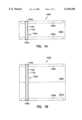
- FIG. 1Ais an elevational view of an embodiment of the present invention.
- Electronic system 105aincludes semiconductor wafer 100a.
- Semiconductor wafer 100aincludes at least one optical fiber 102a that provides a path for transmitting signals between functional circuit 108a on a first surface of semiconductor wafer 100a and functional circuit 109a on a second, opposite surface of semiconductor wafer 100a. It is noted that a number of optical fibers can be formed through semiconductor wafer 100a.
- Optical fiber 102ais formed in a high aspect ratio hole in semiconductor wafer 100a.
- the high aspect ratio holeis formed using, for example, an anodic etching technique as described in more detail below.
- the high aspect ratio holeshave an aspect ratio in the range of approximately 100 to 200.
- a semiconductor waferhas a thickness in the range of approximately 100 to 1000 microns.
- the high aspect ratio holes used to form the optical fiberscan be fabricated with a width that is in the range from approximately 0.5 microns to approximately 10 microns.
- Optical fiber 102ais coupled to functional circuits 108a and 109a.
- optical transmitter 104ais coupled to one end of optical fiber 102a and optical receiver 106a is coupled to a second, opposite end of optical fiber 102a.
- Optical transmitter 104ais also coupled to a node of functional circuit 108a and optical receiver 106a is coupled to a node of functional circuit 109a.
- optical transmitter 104acomprises a gallium arsenide transmitter that is bonded to the first surface of semiconductor wafer 100a using conventional wafer bonding techniques.
- optical receiver 106acomprises a silicon photodiode detector formed in the second surface of semiconductor wafer 100a.
- other appropriate optical receivers and transmittersmay be used to transmit signals over optical fiber 102a.
- Optical fiber 102acomprises cladding layer 112a that separates core 110a from semiconductor wafer 100a
- semiconductor wafer 100aacts as the outer "sheath" for optical fiber 102a.
- Various materialscan be used to form core 110a and cladding layer 112a.
- core 110acomprise a material with a higher index of refraction than the material of cladding layer 112a and thus provides normal optical fiber waveguide characteristics. Specific examples of materials for core 110a and cladding layer 112a are provided below with respect to FIGS. 6 and 7.
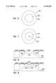
- the optical fiberis formed in a wafer of semiconductor material, absorption by and radiation in the semiconductor wafer can affect the operation of the optical fiber. For example, if the wavelength of the light transmitted in optical fiber 102a is greater than the absorption edge of the semiconductor wafer, e.g., 1.1 microns for silicon, then semiconductor wafer 100a will not absorb the light transmitted in optical fiber 102a. However, due to the large change in index of refraction at the interface between cladding layer 112a and semiconductor wafer 100a, some radiation loss occurs into semiconductor wafer 100a. This case is depicted, for example, in FIG. 8.
- FIG. 8is a graph that illustrates the magnitude of the radiation in optical fiber 102a along a diameter of optical fiber 102a.
- core 256In the region of core 256, indicated at 801, optical waves are guided with no substantial loss along the length of optical fiber 102a.
- Evanescent fieldsare present in the region of cladding layer 254 as indicated at 802. These evanescent fields drop off to insignificant levels as indicated at 800 in the surrounding semiconductor wafer.
- the hole that houses the optical fibercan be lined with a reflecting metal mirror prior to forming the cladding layer.
- a technique for forming the metal layeris described in co-pending application Ser. No. 09/031,961, entitled Integrated Circuits Using Optical Waveguide Interconnects Formed Through a Semiconductor Wafer and Methods for Forming Same, which application is incorporated by reference.
- Optical fiberscan be added to circuits using a conventional layout for the circuit without adversely affecting the surface area requirements of the circuit.
- Conventional circuitstypically include pads formed on the top surface of the semiconductor wafer that are used to connect to leads of the integrated circuit through bonding wires.
- the bonding wires of conventional circuitscan be replaced by optical fibers 102a to allow signals to be passed between various integrated circuits of electronic system 105a without the need to attach the individual integrated circuits to a printed circuit board. This allows a substantial space savings in the design of electrical systems along with overcoming concerns related to signal loss or dissipation and interference with and by other integrated circuitry devices in the electrical system.
- FIGS. 1B and 1Cshow additional embodiments of electronic systems using optical fibers formed through integrated circuits to interconnect various integrated circuits.
- integrated circuits 108b and 109bare formed in working surfaces of semiconductor wafers 100b and 101b. Surfaces opposite the working surfaces of semiconductor wafers 100b and 101b are bonded together using conventional wafer bonding techniques.
- Optical fiber 102btransmits signals between integrated circuits 108b and 109b. A portion of optical fiber 102b is formed in each of the semiconductor wafers 100b and 101b.
- FIG. 1Bintegrated circuits 108b and 109b are formed in working surfaces of semiconductor wafers 100b and 101b.
- semiconductor wafers 100c and 101care stacked with the working surface of semiconductor wafer 101c beneath the surface of semiconductor wafer 100c that is opposite the working surface of semiconductor wafer 100c.
- optical fiber 102cis formed within semiconductor wafer 100c.
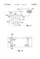
- FIGS. 2, 3, 4, 5, 6, and 7are views of semiconductor wafer 200 at various points of an illustrative embodiment of a method for forming optical fibers through a semiconductor wafer according to the teachings of the present invention.
- Functional circuit 202is formed in an active region of semiconductor wafer 200.
- the Figuresonly show the formation of two optical fibers through semiconductor wafer 200.
- the optical fibersare formed in the same space on the surface of semiconductor wafer 200 that is conventionally used to form bonding pads for leads.
- the leads of the integrated circuitare connected to a printed circuit board which routes signals to other integrated circuits.
- the optical fibersadvantageously remove the need for a printed circuit board to interconnect the functional circuits formed on individual semiconductor wafers.
- photo resist layer 204is formed on surface 206 of semiconductor substrate 200. Photo resist layer 204 is patterned to provide openings 208 at points on surface 206 where high aspect ratio holes are to be formed through semiconductor wafer 200.
- etch pits 210are formed by standard alkaline etching through openings 208 in photo resist layer 204. Photo resist layer 204 is then removed.
- FIG. 4is a schematic diagram that illustrates an embodiment of a layout of equipment used to carry out an anodic etch that is used to form high aspect ratio holes 250 of FIG. 5.
- holes 250have an aspect ratio in the range of 100 to 200.
- Bottom surface 262 of semiconductor wafer 200is coupled to voltage source 234 by positive electrode 230.
- negative electrode 232is coupled to voltage source 234 and is placed in a bath of 6% aqueous solution of hydrofluoric acid (HF) on surface 206 of semiconductor wafer 200.
- HFhydrofluoric acid
- illumination equipment 236is also included because semiconductor wafer 200 is n-type semiconductor material. When p-type semiconductor material is used, the illumination equipment is not required. Illumination equipment 236 assures that there is a sufficient concentration of holes in semiconductor wafer 200 as required by the anodic etching process. Illumination equipment 236 includes lamp 238, IR filter 240, and lens 242. Illumination equipment 236 focuses light on surface 262 of semiconductor wafer 200.
- the anodic etchetches high aspect ratio holes through semiconductor wafer 200 at the location of etch pits 210.
- Voltage source 234is turned on and provides a voltage across positive and negative electrodes 230 and 232.
- Etching currentflows from surface 206 to positive electrode 230. This current forms the high aspect ratio holes through semiconductor wafer 200.
- illumination equipmentilluminates surface 262 of semiconductor wafer 200 so as to assure a sufficient concentration of holes for the anodic etching process.
- the size and shape of the high aspect ratio holes through semiconductor wafer 200depends on, for example, the anodization parameters such as HF concentration, current density, and light illumination.
- An anodic etching processis described in V. Lehmann, The Physics of Macropore Formation in Low Doped n-Type Silicon, J. Electrochem. Soc., Vol. 140, No. 10, pp. 2836-2843, October 1993, which is incorporated herein by reference.
- cladding layer 254is formed on surface 252 of high aspect ratio holes 250. Further, core 256 is formed within hole 250 such that cladding layer 254 and core 256 comprise optical fiber 258.
- Core 256has an index of refraction that is greater than the index of refraction of cladding layer 254.
- Cladding layer 254may comprise, for example, a transparent dielectric film such as silicon oxide (SiO 2 ), aluminum oxide (Al 2 O 3 ), a nitride, other oxide, or other appropriate dielectric material. Cladding layer 254 is deposited with a uniformity that allows light to be transmitted through optical fiber 258 with normal optical fiber waveguide characteristics. When a nitride is used, cladding layer 254 can be deposited with the required uniformity using the technique described in K. P. Muller, et al, Trench Node Technology for Gigabit DRAM Generations, 1996 IEDM Technical Digest, p.
- atomic layer epitaxyhas been described for use with the deposition of silicon oxide (SiO 2 ), See J. W. Klaus, et al, Atomic Layer Controlled Growth of SiO 2 Films Using Binary Reaction Sequence Chemistry, Appl. Phys. Lett. 70(9), Mar. 3, 1997, pp. 1092-1094, which is incorporated by reference. Further, atomic layer epitaxy has been described for use with deposition of aluminum oxide (Al 2 O 3 ). The atomic layer epitaxy technique deposits material with a thickness of 1 to 2 angstroms for a single binary reaction sequence. Thus, the technique advantageously allows the high aspect ratio holes that house the optical fibers to be lined with a uniform cladding layer.
- optical fiber 258transmits light with a wavelength that is greater than 1.1 microns.
- cladding layer 254comprises silicon oxide (SiO 2 ) with an index of refraction of approximately 1.5 or aluminum oxide (Al 2 O 3 ) with an index of refraction of approximately 1.7.
- Core 256comprises lightly doped polysilicon. The lightly doped polysilicon has an index of refraction of approximately 3.4 and exhibits low optical absorption at wavelengths of greater than 1.1 microns.
- Optical fiber 258 of this embodimentis shown in cross section in FIG. 6.
- cladding layer 254comprises silicon oxide (SiO 2 ) and core 256 comprises an oxide or nitride with a higher index of refraction, e.g., aluminum oxide (Al 2 O 3 ).
- a cross section of optical fiber 258 of this embodimentis shown in FIG. 7.
- Core 256does not completely fill the center of optical fiber 258.
- Hole 262extends along the length of core 256 through semiconductor wafer 200. However, as long as hole 262 has a diameter that is less than 0.59 times the wavelength of the light transmitted over optical fiber 258, the light will still be guided by core 256 as shown in FIG. 9.
- This embodimentcan transport light with a wavelength that is less than 1.1 microns. This allows a gallium arsenide emitter to be used at one end of optical fiber 258 to transmit signals down optical fiber 258 and a simple silicon photodiode detector to be used as the receiver on the opposite end of optical fiber 258.
- FIG. 9is a graph that illustrates the magnitude of the radiation in an optical fiber of the type shown in FIG. 7 along a diameter of the optical fiber.
- an evanescent fieldis present as indicated at 900.
- Radi in the optical fiberis guided along the length of the fiber without significant loss in intensity.
- Evanescent fieldsare present in the region of cladding layer 254 as indicated at 904. These evanescent fields drop off to insignificant levels as indicated at 906 in the surrounding semiconductor wafer.
- optical fibersaccording to the teachings of the present invention allows electronic systems to be constructed in less physical space compared to conventional electronic systems by removing the need for large printed circuit boards to interconnect various integrated circuits. This also provides the advantage of reducing the cost of packaging integrated circuits for a particular electronic system by allowing a number of circuits to be packaged together. Further, using the optical fibers assures the electrical integrity of interconnections between integrated circuits by reducing the physical length of electrical interconnections between devices. This reduces concerns with signal loss or dissipation and interference with and by other integrated circuitry devices.
Landscapes
- Physics & Mathematics (AREA)
- General Physics & Mathematics (AREA)
- Optics & Photonics (AREA)
- Condensed Matter Physics & Semiconductors (AREA)
- Engineering & Computer Science (AREA)
- Computer Hardware Design (AREA)
- Microelectronics & Electronic Packaging (AREA)
- Power Engineering (AREA)
- Optical Couplings Of Light Guides (AREA)
- Optical Integrated Circuits (AREA)
Abstract
Description
Claims (22)
Priority Applications (4)
| Application Number | Priority Date | Filing Date | Title |
|---|---|---|---|
| US09/031,975US6150188A (en) | 1998-02-26 | 1998-02-26 | Integrated circuits using optical fiber interconnects formed through a semiconductor wafer and methods for forming same |
| US09/642,960US6526191B1 (en) | 1998-02-26 | 2000-08-21 | Integrated circuits using optical fiber interconnects formed through a semiconductor wafer and methods for forming same |
| US09/650,569US6723577B1 (en) | 1998-02-26 | 2000-08-30 | Method of forming an optical fiber interconnect through a semiconductor wafer |
| US10/772,606US6995443B2 (en) | 1998-02-26 | 2004-02-05 | Integrated circuits using optical fiber interconnects formed through a semiconductor wafer |
Applications Claiming Priority (1)
| Application Number | Priority Date | Filing Date | Title |
|---|---|---|---|
| US09/031,975US6150188A (en) | 1998-02-26 | 1998-02-26 | Integrated circuits using optical fiber interconnects formed through a semiconductor wafer and methods for forming same |
Related Child Applications (2)
| Application Number | Title | Priority Date | Filing Date |
|---|---|---|---|
| US09/642,960DivisionUS6526191B1 (en) | 1998-02-26 | 2000-08-21 | Integrated circuits using optical fiber interconnects formed through a semiconductor wafer and methods for forming same |
| US09/650,569ContinuationUS6723577B1 (en) | 1998-02-26 | 2000-08-30 | Method of forming an optical fiber interconnect through a semiconductor wafer |
Publications (1)
| Publication Number | Publication Date |
|---|---|
| US6150188Atrue US6150188A (en) | 2000-11-21 |
Family
ID=21862434
Family Applications (4)
| Application Number | Title | Priority Date | Filing Date |
|---|---|---|---|
| US09/031,975Expired - LifetimeUS6150188A (en) | 1998-02-26 | 1998-02-26 | Integrated circuits using optical fiber interconnects formed through a semiconductor wafer and methods for forming same |
| US09/642,960Expired - LifetimeUS6526191B1 (en) | 1998-02-26 | 2000-08-21 | Integrated circuits using optical fiber interconnects formed through a semiconductor wafer and methods for forming same |
| US09/650,569Expired - Fee RelatedUS6723577B1 (en) | 1998-02-26 | 2000-08-30 | Method of forming an optical fiber interconnect through a semiconductor wafer |
| US10/772,606Expired - Fee RelatedUS6995443B2 (en) | 1998-02-26 | 2004-02-05 | Integrated circuits using optical fiber interconnects formed through a semiconductor wafer |
Family Applications After (3)
| Application Number | Title | Priority Date | Filing Date |
|---|---|---|---|
| US09/642,960Expired - LifetimeUS6526191B1 (en) | 1998-02-26 | 2000-08-21 | Integrated circuits using optical fiber interconnects formed through a semiconductor wafer and methods for forming same |
| US09/650,569Expired - Fee RelatedUS6723577B1 (en) | 1998-02-26 | 2000-08-30 | Method of forming an optical fiber interconnect through a semiconductor wafer |
| US10/772,606Expired - Fee RelatedUS6995443B2 (en) | 1998-02-26 | 2004-02-05 | Integrated circuits using optical fiber interconnects formed through a semiconductor wafer |
Country Status (1)
| Country | Link |
|---|---|
| US (4) | US6150188A (en) |
Cited By (43)
| Publication number | Priority date | Publication date | Assignee | Title |
|---|---|---|---|---|
| US6393169B1 (en)* | 1997-12-19 | 2002-05-21 | Intel Corporation | Method and apparatus for providing optical interconnection |
| US6410941B1 (en)* | 2000-06-30 | 2002-06-25 | Motorola, Inc. | Reconfigurable systems using hybrid integrated circuits with optical ports |
| US20020135543A1 (en)* | 2001-03-26 | 2002-09-26 | Seiko Epson Corporation | Display device and method for manufacturing the same |
| US6493477B2 (en)* | 2001-01-22 | 2002-12-10 | Pioneer Corporation | Optical integrated circuit and manufacturing method therefor |
| US6526191B1 (en)* | 1998-02-26 | 2003-02-25 | Micron Technology, Inc. | Integrated circuits using optical fiber interconnects formed through a semiconductor wafer and methods for forming same |
| US20030174986A1 (en)* | 2002-03-13 | 2003-09-18 | Micron Technology, Inc. | Hollow core photonic bandgap optical fiber |
| US20030197186A1 (en)* | 1998-02-26 | 2003-10-23 | Micron Technology, Inc. | Integrated circuits using optical waveguide interconnects formed through a semiconductor wafer and methods for forming same |
| US20040042722A1 (en)* | 2002-08-29 | 2004-03-04 | Micron Technology, Inc. | Resistive heater for thermo optic device |
| US6709978B2 (en) | 1998-01-20 | 2004-03-23 | Micron Technology, Inc. | Method for forming integrated circuits using high aspect ratio vias through a semiconductor wafer |
| US20040057687A1 (en)* | 2002-08-29 | 2004-03-25 | Micron Technology, Inc. | Resonator for thermo optic device |
| US6716657B1 (en)* | 2000-05-26 | 2004-04-06 | Agere Systems Inc | Method for interconnecting arrays of micromechanical devices |
| US6720661B2 (en)* | 2000-06-02 | 2004-04-13 | Seiko Epson Corporation | Semiconductor device, method of fabricating the same, stack-type semiconductor device, circuit board and electronic instrument |
| US6798931B2 (en)* | 2001-03-06 | 2004-09-28 | Digital Optics Corp. | Separating of optical integrated modules and structures formed thereby |
| US6806111B1 (en) | 2002-12-19 | 2004-10-19 | Advanced Micro Devices, Inc. | Semiconductor component and method of manufacture |
| US20040233514A1 (en)* | 2003-02-18 | 2004-11-25 | Masahiro Takagi | Fluorescent glass, optical amplification waveguide and optical amplification module |
| US20050013527A1 (en)* | 2003-07-18 | 2005-01-20 | International Business Machines Corporation | Fiber optic transmission lines on an soc |
| US20050031284A1 (en)* | 2002-08-29 | 2005-02-10 | Micron Technology, Inc., Clarendon Photonics | Waveguide for thermo optic device |
| US20050046034A1 (en)* | 2003-09-03 | 2005-03-03 | Micron Technology, Inc. | Apparatus and method for high density multi-chip structures |
| US7081421B2 (en) | 2004-08-26 | 2006-07-25 | Micron Technology, Inc. | Lanthanide oxide dielectric layer |
| US7259434B2 (en) | 2001-08-30 | 2007-08-21 | Micron Technology, Inc. | Highly reliable amorphous high-k gate oxide ZrO2 |
| US20080048282A1 (en)* | 2006-08-23 | 2008-02-28 | Jae Won Han | Semiconductor Device and Fabricating Method Thereof |
| US7374964B2 (en) | 2005-02-10 | 2008-05-20 | Micron Technology, Inc. | Atomic layer deposition of CeO2/Al2O3 films as gate dielectrics |
| US7405454B2 (en) | 2003-03-04 | 2008-07-29 | Micron Technology, Inc. | Electronic apparatus with deposited dielectric layers |
| US7410910B2 (en) | 2005-08-31 | 2008-08-12 | Micron Technology, Inc. | Lanthanum aluminum oxynitride dielectric films |
| US20080226219A1 (en)* | 2007-03-13 | 2008-09-18 | Micron Technology, Inc. | Zinc oxide optical waveguides |
| US20080226220A1 (en)* | 2007-03-13 | 2008-09-18 | Micron Technology, Inc. | Zinc oxide diodes for optical interconnections |
| US20080251707A1 (en)* | 2001-10-23 | 2008-10-16 | Tessera North America | Optical chassis, camera having an optical chassis, and associated methods |
| US7494939B2 (en) | 2004-08-31 | 2009-02-24 | Micron Technology, Inc. | Methods for forming a lanthanum-metal oxide dielectric layer |
| US7545674B2 (en) | 2001-08-30 | 2009-06-09 | Micron Technology, Inc. | Flash memory with low tunnel barrier interpoly insulators |
| US7560793B2 (en) | 2002-05-02 | 2009-07-14 | Micron Technology, Inc. | Atomic layer deposition and conversion |
| EP2138471A1 (en)* | 2008-06-25 | 2009-12-30 | Acreo AB | Atomic layer deposition of hydrogen barrier coatings on optical fibers |
| US7662729B2 (en) | 2005-04-28 | 2010-02-16 | Micron Technology, Inc. | Atomic layer deposition of a ruthenium layer to a lanthanide oxide dielectric layer |
| US7670646B2 (en) | 2002-05-02 | 2010-03-02 | Micron Technology, Inc. | Methods for atomic-layer deposition |
| US7687848B2 (en) | 2002-07-08 | 2010-03-30 | Micron Technology, Inc. | Memory utilizing oxide-conductor nanolaminates |
| US7709402B2 (en) | 2006-02-16 | 2010-05-04 | Micron Technology, Inc. | Conductive layers for hafnium silicon oxynitride films |
| US7728626B2 (en) | 2002-07-08 | 2010-06-01 | Micron Technology, Inc. | Memory utilizing oxide nanolaminates |
| US20100276748A1 (en)* | 2007-06-28 | 2010-11-04 | Ahn Kie Y | Method of forming lutetium and lanthanum dielectric structures |
| US8071476B2 (en) | 2005-08-31 | 2011-12-06 | Micron Technology, Inc. | Cobalt titanium oxide dielectric films |
| US20120013368A1 (en)* | 2001-10-15 | 2012-01-19 | Micron Technology, Inc. | Method and system for electrically coupling a chip to chip package |
| US8233757B2 (en) | 2001-10-23 | 2012-07-31 | Digitaloptics Corporation East | Wafer based optical chassis and associated methods |
| US8501563B2 (en) | 2005-07-20 | 2013-08-06 | Micron Technology, Inc. | Devices with nanocrystals and methods of formation |
| US9685576B2 (en) | 2014-10-03 | 2017-06-20 | Omnivision Technologies, Inc. | Back side illuminated image sensor with guard ring region reflecting structure |
| US9825073B2 (en)* | 2014-05-23 | 2017-11-21 | Omnivision Technologies, Inc. | Enhanced back side illuminated near infrared image sensor |
Families Citing this family (23)
| Publication number | Priority date | Publication date | Assignee | Title |
|---|---|---|---|---|
| US6731843B2 (en)* | 2000-12-29 | 2004-05-04 | Intel Corporation | Multi-level waveguide |
| CN1564952A (en)* | 2001-10-04 | 2005-01-12 | 关西油漆株式会社 | Optical waveguide sheet and production method thereof |
| US6900122B2 (en)* | 2001-12-20 | 2005-05-31 | Micron Technology, Inc. | Low-temperature grown high-quality ultra-thin praseodymium gate dielectrics |
| AU2003238889A1 (en)* | 2002-06-04 | 2003-12-19 | Lake Shore Cryotronics, Inc. | Spectral filter for green and shorter wavelengths and method of manufacturing same |
| US7084078B2 (en) | 2002-08-29 | 2006-08-01 | Micron Technology, Inc. | Atomic layer deposited lanthanide doped TiOx dielectric films |
| EP1552328A4 (en)* | 2002-10-16 | 2005-12-14 | Lake Shore Cryotronics Inc | Spectral filter for green and longer wavelengths |
| US20050058414A1 (en)* | 2003-08-21 | 2005-03-17 | Lake Shore Cryotronics, Inc. | Porous retroreflection suppression plates, optical isolators and method of fabricating same |
| US7248757B2 (en)* | 2003-12-15 | 2007-07-24 | Canon Kabushiki Kaisha | Method, device and computer program for designing a circuit having electric wires and optical connections |
| US7199050B2 (en) | 2004-08-24 | 2007-04-03 | Micron Technology, Inc. | Pass through via technology for use during the manufacture of a semiconductor device |
| US20060125030A1 (en)* | 2004-12-13 | 2006-06-15 | Micron Technology, Inc. | Hybrid ALD-CVD of PrxOy/ZrO2 films as gate dielectrics |
| TWI293499B (en)* | 2006-01-25 | 2008-02-11 | Advanced Semiconductor Eng | Three dimensional package and method of making the same |
| TWI287273B (en)* | 2006-01-25 | 2007-09-21 | Advanced Semiconductor Eng | Three dimensional package and method of making the same |
| US20080232761A1 (en)* | 2006-09-20 | 2008-09-25 | Raveen Kumaran | Methods of making optical waveguide structures by way of molecular beam epitaxy |
| WO2008047240A2 (en)* | 2006-09-20 | 2008-04-24 | Zecotek Medical Systems Inc. | Methods of making optical waveguide structures by way of molecular beam epitaxy |
| US7778501B2 (en)* | 2007-04-03 | 2010-08-17 | Hewlett-Packard Development Company, L.P. | Integrated circuits having photonic interconnect layers and methods for fabricating same |
| US20090153229A1 (en)* | 2007-12-14 | 2009-06-18 | Andre Hanke | Method for Signal Transmission between Semiconductor Substrates, and Semiconductor Component Comprising Such Semiconductor Substrates |
| WO2009090687A1 (en)* | 2008-01-18 | 2009-07-23 | Anritsu Corporation | Optical modulator |
| US7831115B2 (en)* | 2008-03-20 | 2010-11-09 | Intel Corporation | Optical die structures and associated package substrates |
| US8350210B1 (en)* | 2008-06-03 | 2013-01-08 | Wavefront Research, Inc. | Embedded optical interconnect devices and methods of use thereof |
| US8137995B2 (en)* | 2008-12-11 | 2012-03-20 | Stats Chippac, Ltd. | Double-sided semiconductor device and method of forming top-side and bottom-side interconnect structures |
| US9116319B2 (en)* | 2010-12-17 | 2015-08-25 | Stmicroelectronics, Inc. | Photonic integrated circuit having a plurality of lenses |
| US9256027B2 (en) | 2012-07-02 | 2016-02-09 | Stmicroelectronics S.R.L. | Integrated optoelectronic device and system with waveguide and manufacturing process thereof |
| ITTO20120583A1 (en) | 2012-07-02 | 2014-01-03 | St Microelectronics Srl | INTEGRATED OPTOELECTRONIC DEVICE WITH WAVE GUIDE AND ITS MANUFACTURING PROCEDURE |
Citations (33)
| Publication number | Priority date | Publication date | Assignee | Title |
|---|---|---|---|---|
| US3968564A (en)* | 1975-04-30 | 1976-07-13 | Northern Electric Company Limited | Alignment of optical fibers to light emitting diodes |
| US4744623A (en)* | 1985-10-16 | 1988-05-17 | The Trustees Of Columbia University In The City Of New York | Integrated fiber optic coupler for VHSIC/VLSI interconnects |
| US4920070A (en)* | 1987-02-19 | 1990-04-24 | Fujitsu Limited | Method for forming wirings for a semiconductor device by filling very narrow via holes |
| US4970578A (en)* | 1987-05-01 | 1990-11-13 | Raytheon Company | Selective backside plating of GaAs monolithic microwave integrated circuits |
| JPH0313907A (en)* | 1989-06-13 | 1991-01-22 | Fujikura Ltd | Production of substrate type optical waveguide |
| WO1991011833A1 (en)* | 1990-01-26 | 1991-08-08 | Commtech International | Chip interconnect with high density of vias |
| US5128831A (en)* | 1991-10-31 | 1992-07-07 | Micron Technology, Inc. | High-density electronic package comprising stacked sub-modules which are electrically interconnected by solder-filled vias |
| US5221633A (en)* | 1991-09-09 | 1993-06-22 | Motorola, Inc. | Method of manufacturing a distributed drive optoelectronic integrated circuit |
| WO1994005039A1 (en)* | 1992-08-20 | 1994-03-03 | Capps David A | Semiconductor wafer for lamination applications |
| US5352998A (en)* | 1992-10-09 | 1994-10-04 | Mitsubishi Denki Kabushiki Kaisha | Microwave integrated circuit having a passive circuit substrate mounted on a semiconductor circuit substrate |
| US5362976A (en)* | 1991-10-26 | 1994-11-08 | Nec Corporation | High frequency semiconductor device having optical guide package structure |
| US5409563A (en)* | 1993-02-26 | 1995-04-25 | Micron Technology, Inc. | Method for etching high aspect ratio features |
| US5489554A (en)* | 1992-07-21 | 1996-02-06 | Hughes Aircraft Company | Method of making a 3-dimensional circuit assembly having electrical contacts that extend through the IC layer |
| US5532506A (en)* | 1994-08-31 | 1996-07-02 | Texas Instruments Incorporated | Integrated circuit adapted for improved thermal impedance |
| US5604835A (en)* | 1993-12-27 | 1997-02-18 | Hitachi, Ltd. | Integrated optical waveguide device |
| US5641545A (en)* | 1995-06-07 | 1997-06-24 | Micron Technology, Inc. | Method to deposit highly conformal CVD films |
| US5656548A (en)* | 1993-09-30 | 1997-08-12 | Kopin Corporation | Method for forming three dimensional processor using transferred thin film circuits |
| US5682062A (en)* | 1995-06-05 | 1997-10-28 | Harris Corporation | System for interconnecting stacked integrated circuits |
| US5729038A (en)* | 1995-12-15 | 1998-03-17 | Harris Corporation | Silicon-glass bonded wafers |
| US5742100A (en)* | 1995-03-27 | 1998-04-21 | Motorola, Inc. | Structure having flip-chip connected substrates |
| US5760478A (en)* | 1996-08-20 | 1998-06-02 | International Business Machines Corporation | Clock skew minimization system and method for integrated circuits |
| US5767001A (en)* | 1993-05-05 | 1998-06-16 | Siemens Aktiengesellschaft | Process for producing semiconductor components between which contact is made vertically |
| US5798297A (en)* | 1993-05-05 | 1998-08-25 | Siemens Aktiengesellschaft | Method for producing a semiconductor component with electrical connection terminals for high integration density |
| US5834849A (en)* | 1996-02-13 | 1998-11-10 | Altera Corporation | High density integrated circuit pad structures |
| US5844289A (en)* | 1996-05-21 | 1998-12-01 | Nec Corporation | Solid-state image sensor with microlens and optical fiber bundle |
| US5858814A (en)* | 1996-07-17 | 1999-01-12 | Lucent Technologies Inc. | Hybrid chip and method therefor |
| US5897333A (en)* | 1997-03-14 | 1999-04-27 | Lucent Technologies, Inc. | Method for forming integrated composite semiconductor devices |
| US5901050A (en)* | 1996-08-21 | 1999-05-04 | Ngk Spark Plug Co., Ltd. | Wired base plate and package for electronic parts |
| US5900674A (en)* | 1996-12-23 | 1999-05-04 | General Electric Company | Interface structures for electronic devices |
| US5903045A (en)* | 1996-04-30 | 1999-05-11 | International Business Machines Corporation | Self-aligned connector for stacked chip module |
| US5902118A (en)* | 1994-07-05 | 1999-05-11 | Siemens Aktiengesellschaft | Method for production of a three-dimensional circuit arrangement |
| US5915167A (en)* | 1997-04-04 | 1999-06-22 | Elm Technology Corporation | Three dimensional structure memory |
| US5952665A (en)* | 1997-11-28 | 1999-09-14 | Nanocrystals Technology L.P. | Composite nanophosphor screen for detecting radiation |
Family Cites Families (28)
| Publication number | Priority date | Publication date | Assignee | Title |
|---|---|---|---|---|
| US4452508A (en)* | 1977-06-28 | 1984-06-05 | British Telecommunications | Graded index optical fibres |
| JPS5655067A (en) | 1979-10-11 | 1981-05-15 | Matsushita Electric Ind Co Ltd | Semiconductor integrated circuit device |
| JPS61258468A (en) | 1985-05-13 | 1986-11-15 | Hitachi Ltd | Semiconductor memory device and manufacture of the same |
| US5039189A (en)* | 1990-04-06 | 1991-08-13 | Lockheed Missiles & Space Company, Inc. | Optical signal distribution network and method of converting independent optical/electrical signals |
| DE4013306A1 (en)* | 1990-04-26 | 1991-10-31 | Hoechst Ag | OPTICAL MOLDED BODIES MADE OF SILICON NITRIDE, AND METHOD FOR THE PRODUCTION THEREOF |
| JPH04263462A (en) | 1991-02-18 | 1992-09-18 | Fujitsu Ltd | Semiconductor device and manufacture thereof |
| US5312765A (en) | 1991-06-28 | 1994-05-17 | Hughes Aircraft Company | Method of fabricating three dimensional gallium arsenide microelectronic device |
| US5200631A (en)* | 1991-08-06 | 1993-04-06 | International Business Machines Corporation | High speed optical interconnect |
| JPH05145060A (en) | 1991-11-22 | 1993-06-11 | Nec Corp | Structure of semiconductor contact hole and manufacture thereof |
| US5651855A (en) | 1992-07-28 | 1997-07-29 | Micron Technology, Inc. | Method of making self aligned contacts to silicon substrates during the manufacture of integrated circuits |
| US5416872A (en)* | 1993-07-06 | 1995-05-16 | At&T Corp. | Arrangement for interconnecting an optical fiber an optoelectronic component |
| US5431775A (en)* | 1994-07-29 | 1995-07-11 | Eastman Kodak Company | Method of forming optical light guides through silicon |
| US5587119A (en) | 1994-09-14 | 1996-12-24 | E-Systems, Inc. | Method for manufacturing a coaxial interconnect |
| US5796714A (en) | 1994-09-28 | 1998-08-18 | Matsushita Electric Industrial Co., Ltd. | Optical module having a vertical-cavity surface-emitting laser |
| US5618752A (en) | 1995-06-05 | 1997-04-08 | Harris Corporation | Method of fabrication of surface mountable integrated circuits |
| US5739067A (en)* | 1995-12-07 | 1998-04-14 | Advanced Micro Devices, Inc. | Method for forming active devices on and in exposed surfaces of both sides of a silicon wafer |
| US5652811A (en)* | 1996-03-06 | 1997-07-29 | The United States Of America As Represented By The Secretary Of The Air Force | Semiconductor on fiber optic substrate (SOFOS) |
| JPH1051247A (en) | 1996-07-29 | 1998-02-20 | Toshiba Corp | Fully differential analog circuit |
| JP3347615B2 (en)* | 1996-11-28 | 2002-11-20 | 富士通株式会社 | Semiconductor integrated circuit and optical transmission module |
| US5848214A (en)* | 1997-07-16 | 1998-12-08 | The United States Of America As Represented By The Secretary Of The Air Force | Optically-guiding multichip module |
| KR100248054B1 (en)* | 1997-08-14 | 2000-03-15 | 윤종용 | Fiber Array Module Using Soldering and Manufacturing Method |
| US6187677B1 (en) | 1997-08-22 | 2001-02-13 | Micron Technology, Inc. | Integrated circuitry and methods of forming integrated circuitry |
| US6143616A (en) | 1997-08-22 | 2000-11-07 | Micron Technology, Inc. | Methods of forming coaxial integrated circuitry interconnect lines |
| US6198168B1 (en)* | 1998-01-20 | 2001-03-06 | Micron Technologies, Inc. | Integrated circuits using high aspect ratio vias through a semiconductor wafer and method for forming same |
| US6090636A (en) | 1998-02-26 | 2000-07-18 | Micron Technology, Inc. | Integrated circuits using optical waveguide interconnects formed through a semiconductor wafer and methods for forming same |
| US6150188A (en)* | 1998-02-26 | 2000-11-21 | Micron Technology Inc. | Integrated circuits using optical fiber interconnects formed through a semiconductor wafer and methods for forming same |
| US6281042B1 (en) | 1998-08-31 | 2001-08-28 | Micron Technology, Inc. | Structure and method for a high performance electronic packaging assembly |
| US6122187A (en) | 1998-11-23 | 2000-09-19 | Micron Technology, Inc. | Stacked integrated circuits |
- 1998
- 1998-02-26USUS09/031,975patent/US6150188A/ennot_activeExpired - Lifetime
- 2000
- 2000-08-21USUS09/642,960patent/US6526191B1/ennot_activeExpired - Lifetime
- 2000-08-30USUS09/650,569patent/US6723577B1/ennot_activeExpired - Fee Related
- 2004
- 2004-02-05USUS10/772,606patent/US6995443B2/ennot_activeExpired - Fee Related
Patent Citations (33)
| Publication number | Priority date | Publication date | Assignee | Title |
|---|---|---|---|---|
| US3968564A (en)* | 1975-04-30 | 1976-07-13 | Northern Electric Company Limited | Alignment of optical fibers to light emitting diodes |
| US4744623A (en)* | 1985-10-16 | 1988-05-17 | The Trustees Of Columbia University In The City Of New York | Integrated fiber optic coupler for VHSIC/VLSI interconnects |
| US4920070A (en)* | 1987-02-19 | 1990-04-24 | Fujitsu Limited | Method for forming wirings for a semiconductor device by filling very narrow via holes |
| US4970578A (en)* | 1987-05-01 | 1990-11-13 | Raytheon Company | Selective backside plating of GaAs monolithic microwave integrated circuits |
| JPH0313907A (en)* | 1989-06-13 | 1991-01-22 | Fujikura Ltd | Production of substrate type optical waveguide |
| WO1991011833A1 (en)* | 1990-01-26 | 1991-08-08 | Commtech International | Chip interconnect with high density of vias |
| US5221633A (en)* | 1991-09-09 | 1993-06-22 | Motorola, Inc. | Method of manufacturing a distributed drive optoelectronic integrated circuit |
| US5362976A (en)* | 1991-10-26 | 1994-11-08 | Nec Corporation | High frequency semiconductor device having optical guide package structure |
| US5128831A (en)* | 1991-10-31 | 1992-07-07 | Micron Technology, Inc. | High-density electronic package comprising stacked sub-modules which are electrically interconnected by solder-filled vias |
| US5489554A (en)* | 1992-07-21 | 1996-02-06 | Hughes Aircraft Company | Method of making a 3-dimensional circuit assembly having electrical contacts that extend through the IC layer |
| WO1994005039A1 (en)* | 1992-08-20 | 1994-03-03 | Capps David A | Semiconductor wafer for lamination applications |
| US5352998A (en)* | 1992-10-09 | 1994-10-04 | Mitsubishi Denki Kabushiki Kaisha | Microwave integrated circuit having a passive circuit substrate mounted on a semiconductor circuit substrate |
| US5409563A (en)* | 1993-02-26 | 1995-04-25 | Micron Technology, Inc. | Method for etching high aspect ratio features |
| US5798297A (en)* | 1993-05-05 | 1998-08-25 | Siemens Aktiengesellschaft | Method for producing a semiconductor component with electrical connection terminals for high integration density |
| US5767001A (en)* | 1993-05-05 | 1998-06-16 | Siemens Aktiengesellschaft | Process for producing semiconductor components between which contact is made vertically |
| US5656548A (en)* | 1993-09-30 | 1997-08-12 | Kopin Corporation | Method for forming three dimensional processor using transferred thin film circuits |
| US5604835A (en)* | 1993-12-27 | 1997-02-18 | Hitachi, Ltd. | Integrated optical waveguide device |
| US5902118A (en)* | 1994-07-05 | 1999-05-11 | Siemens Aktiengesellschaft | Method for production of a three-dimensional circuit arrangement |
| US5532506A (en)* | 1994-08-31 | 1996-07-02 | Texas Instruments Incorporated | Integrated circuit adapted for improved thermal impedance |
| US5742100A (en)* | 1995-03-27 | 1998-04-21 | Motorola, Inc. | Structure having flip-chip connected substrates |
| US5682062A (en)* | 1995-06-05 | 1997-10-28 | Harris Corporation | System for interconnecting stacked integrated circuits |
| US5641545A (en)* | 1995-06-07 | 1997-06-24 | Micron Technology, Inc. | Method to deposit highly conformal CVD films |
| US5729038A (en)* | 1995-12-15 | 1998-03-17 | Harris Corporation | Silicon-glass bonded wafers |
| US5834849A (en)* | 1996-02-13 | 1998-11-10 | Altera Corporation | High density integrated circuit pad structures |
| US5903045A (en)* | 1996-04-30 | 1999-05-11 | International Business Machines Corporation | Self-aligned connector for stacked chip module |
| US5844289A (en)* | 1996-05-21 | 1998-12-01 | Nec Corporation | Solid-state image sensor with microlens and optical fiber bundle |
| US5858814A (en)* | 1996-07-17 | 1999-01-12 | Lucent Technologies Inc. | Hybrid chip and method therefor |
| US5760478A (en)* | 1996-08-20 | 1998-06-02 | International Business Machines Corporation | Clock skew minimization system and method for integrated circuits |
| US5901050A (en)* | 1996-08-21 | 1999-05-04 | Ngk Spark Plug Co., Ltd. | Wired base plate and package for electronic parts |
| US5900674A (en)* | 1996-12-23 | 1999-05-04 | General Electric Company | Interface structures for electronic devices |
| US5897333A (en)* | 1997-03-14 | 1999-04-27 | Lucent Technologies, Inc. | Method for forming integrated composite semiconductor devices |
| US5915167A (en)* | 1997-04-04 | 1999-06-22 | Elm Technology Corporation | Three dimensional structure memory |
| US5952665A (en)* | 1997-11-28 | 1999-09-14 | Nanocrystals Technology L.P. | Composite nanophosphor screen for detecting radiation |
Non-Patent Citations (44)
| Title |
|---|
| Forbes, L., et al., "Resonant Forward-Biased Guarding-Ring Diodes for Suppression of Substrate Noise in Mixed-Mode CMOS Circuits", Electronics Letters, 31, 720-721, (Apr. 1995). |
| Forbes, L., et al., Resonant Forward Biased Guarding Ring Diodes for Suppression of Substrate Noise in Mixed Mode CMOS Circuits , Electronics Letters , 31, 720 721, (Apr. 1995).* |
| Foster, R., et al., "High Rate Low-Temperature Selective Tungsten", In: Tungsten and Other Refractory Metals for VLSI Applications III, V.A. Wells, ed., Materials Res. Soc., Pittsburgh, PA, 69-72, (1988). |
| Foster, R., et al., High Rate Low Temperature Selective Tungsten , In: Tungsten and Other Refractory Metals for VLSI Applications III , V.A. Wells, ed., Materials Res. Soc., Pittsburgh, PA, 69 72, (1988).* |
| Gong, S., et al., "Techniques for Reducing Switching Noise in High Speed Digital Systems", Proceedings of the 8th Annual IEEE International ASIC Conference and Exhibit, 21-24 (1995). |
| Gong, S., et al., Techniques for Reducing Switching Noise in High Speed Digital Systems , Proceedings of the 8th Annual IEEE International ASIC Conference and Exhibit , 21 24 (1995).* |
| Heavens, O., Optical Properties of Thin Solid Films , Dover Pubs. Inc., New York, 167, (1965).* |
| Heavens, O., Optical Properties of Thin Solid Films, Dover Pubs. Inc., New York, 167, (1965). |
| Horie, H., et al., "Novel High Aspect Ratio Aluminum Plug for Logic/DRAM LSI's Using Polysilicon-Aluminum Substitute", Technical Digest: IEEE Int. Electron Devices Meeting, San Francisco, CA, 946-948, (1996). |
| Horie, H., et al., Novel High Aspect Ratio Aluminum Plug for Logic/DRAM LSI s Using Polysilicon Aluminum Substitute , Technical Digest: IEEE Int. Electron Devices Meeting , San Francisco, CA, 946 948, (1996).* |
| Kim, Y.S., et al., "A Study on Pyrolysis DMEAA for Selective Deposition of Aluminum", In: Advanced Metallization and Interconnect Systems for ULSI Applications in 1995, R.C. Ellwanger, et al., (eds.), Materials Research Society, Pittsburgh, PA, 675-680, (1996). |
| Kim, Y.S., et al., A Study on Pyrolysis DMEAA for Selective Deposition of Aluminum , In: Advanced Metallization and Interconnect Systems for ULSI Applications in 1995 , R.C. Ellwanger, et al., (eds.), Materials Research Society, Pittsburgh, PA, 675 680, (1996).* |
| Klaus, et al., "Atomic Layer Controlled Growth of SiO2 Films Using Binary Reaction Sequence Chemistry", Applied Physics Lett. 70(9), 1092-94, (Mar. 3, 1997). |
| Klaus, et al., Atomic Layer Controlled Growth of SiO2 Films Using Binary Reaction Sequence Chemistry , Applied Physics Lett. 70(9), 1092 94, (Mar. 3, 1997).* |
| Lehmann, et al., "A Novel Capacitor Technology Based on Porous Silicon", Thin Solid Films 276, Elsevier Science, 138-42, (1996). |
| Lehmann, et al., A Novel Capacitor Technology Based on Porous Silicon , Thin Solid Films 276, Elsevier Science , 138 42, (1996).* |
| Lehmann, V., "The Physics of Macropore Formation in Low Doped n-Type Silicon", J. Electrochem. Soc., 140, 2836-2843, (Oct. 1993). |
| Lehmann, V., The Physics of Macropore Formation in Low Doped n Type Silicon , J. Electrochem. Soc., 140 , 2836 2843, (Oct. 1993).* |
| Masu, K., et al., "Multilevel Metallization Based on Al CVD", 1996 IEEE Symposium on VLSI Technology, Digest of Technical Papers, Honolulu, HI, 44-45, (Jun. 11-13, 1996). |
| Masu, K., et al., Multilevel Metallization Based on Al CVD , 1996 IEEE Symposium on VLSI Technology, Digest of Technical Papers , Honolulu, HI, 44 45, (Jun. 11 13, 1996).* |
| McCredie, B.D., et al., "Modeling, Measurement, and Simulation of Simultaneous Switching Noise", IEEE Transactions on Components, Packaging, and Manufacturing Technology--Part B, 19, 461-472, (Aug. 1996). |
| McCredie, B.D., et al., Modeling, Measurement, and Simulation of Simultaneous Switching Noise , IEEE Transactions on Components, Packaging, and Manufacturing Technology Part B, 19 , 461 472, (Aug. 1996).* |
| Muller, K., et al., "Trench Storage Node Technology for Gigabit DRAM Generations", Digest IEEE Int. Electron Devices Meeting, San Francisco, CA, 594-597, (Dec. 1996). |
| Muller, K., et al., Trench Storage Node Technology for Gigabit DRAM Generations , Digest IEEE Int. Electron Devices Meeting , San Francisco, CA, 594 597, (Dec. 1996).* |
| Ohba, T., et al., "Evaluation on Selective Deposition of CVD W Films by Measurement of Surface Temperature", In: Tungsten and Other Refractory Metals for VLSI Applications II, Materials Research Society, Pittsburgh, PA, 59-66, (1987). |
| Ohba, T., et al., "Selective Chemical Vapor Deposition of Tungsten Using Silane and Polysilane Reductions", In: Tungsten and Other Refractory Metals for VLSI Applications IV, Materials Research Society, Pittsburgh, PA, 17-25, (1989). |
| Ohba, T., et al., Evaluation on Selective Deposition of CVD W Films by Measurement of Surface Temperature , In: Tungsten and Other Refractory Metals for VLSI Applications II , Materials Research Society, Pittsburgh, PA, 59 66, (1987).* |
| Ohba, T., et al., Selective Chemical Vapor Deposition of Tungsten Using Silane and Polysilane Reductions , In: Tungsten and Other Refractory Metals for VLSI Applications IV , Materials Research Society, Pittsburgh, PA, 17 25, (1989).* |
| Ott, A.W., et al., "Al303 Thin Film Growth on Si (100) Using Binary Reaction Sequence Chemistry", Thin Solid Films, vol. 292, 135-44, (1997). |
| Ott, A.W., et al., Al303 Thin Film Growth on Si (100) Using Binary Reaction Sequence Chemistry , Thin Solid Films , vol. 292, 135 44, (1997).* |
| Ramo, S., et al., Fields and Waves in Communication Electronics , John Wiley & Sons, Inc., New York, 428 433, (1993).* |
| Ramo, S., et al., Fields and Waves in Communication Electronics, John Wiley & Sons, Inc., New York, 428-433, (1993). |
| Senthinathan, R., et al., "Reference Plane Parasitics Modeling and Their Contribution to the Power and Ground Path "Effective" Inductance as Seen by the Output Drivers", IEEE Transactions on Microwave Theory and Techniques, 42, 1765-1773, (Sep. 1994). |
| Senthinathan, R., et al., Reference Plane Parasitics Modeling and Their Contribution to the Power and Ground Path Effective Inductance as Seen by the Output Drivers , IEEE Transactions on Microwave Theory and Techniques , 42, 1765 1773, (Sep. 1994).* |
| Stanisic, B.R., et al., "Addressing Noise Decoupling in Mixed-Signal IC's: Power Distribution Design and Cell Customization", IEEE Journal of Solid-State Circuits, 30, 321-236, (Mar. 1995). |
| Stanisic, B.R., et al., Addressing Noise Decoupling in Mixed Signal IC s: Power Distribution Design and Cell Customization , IEEE Journal of Solid State Circuits , 30, 321 236, (Mar. 1995).* |
| Suntola, T., "Atomic Layer Epitaxy", Handbook of Crystal Growth 3, Thin Films of Epitaxy, Part B: Growth Mechanics and Dynamics, Elsevier, Amsterdam, 601-63, (1994). |
| Suntola, T., Atomic Layer Epitaxy , Handbook of Crystal Growth 3, Thin Films of Epitaxy, Part B: Growth Mechanics and Dynamics, Elsevier, Amsterdam , 601 63, (1994).* |
| Sze, S.M., VLSI Technology, 2nd Edition, Mc Graw Hill, NY , 90, (1988).* |
| Sze, S.M., VLSI Technology, 2nd Edition, Mc Graw-Hill, NY, 90, (1988). |
| Vittal, A., et al., "Clock Skew Optimization for Ground Bounce Control", 1996 IEEE/ACM International Conference on Computer-Aided Design, Digest of Technical Papers, San Jose, CA, 395-399, (Nov. 10-14, 1996). |
| Vittal, A., et al., Clock Skew Optimization for Ground Bounce Control , 1996 IEEE/ACM International Conference on Computer Aided Design, Digest of Technical Papers , San Jose, CA, 395 399, (Nov. 10 14, 1996).* |
| Wooley, et al., "Experimental Results and Modeling Techniques for Substrate Noise in Mixed Signal Integrated Circuits", IEEE Journal of Solid State Circuits, vol. SC-28, 420-30, (1993). |
| Wooley, et al., Experimental Results and Modeling Techniques for Substrate Noise in Mixed Signal Integrated Circuits , IEEE Journal of Solid State Circuits , vol. SC 28, 420 30, (1993).* |
Cited By (123)
| Publication number | Priority date | Publication date | Assignee | Title |
|---|---|---|---|---|
| US6393169B1 (en)* | 1997-12-19 | 2002-05-21 | Intel Corporation | Method and apparatus for providing optical interconnection |
| US6709978B2 (en) | 1998-01-20 | 2004-03-23 | Micron Technology, Inc. | Method for forming integrated circuits using high aspect ratio vias through a semiconductor wafer |
| US20040156578A1 (en)* | 1998-02-26 | 2004-08-12 | Micron Technology, Inc. | Integrated circuits using optical fiber interconnects formed through a semiconductor wafer |
| US6995441B2 (en)* | 1998-02-26 | 2006-02-07 | Micron Technology, Inc. | Integrated circuits using optical waveguide interconnects formed through a semiconductor wafer and methods for forming same |
| US6526191B1 (en)* | 1998-02-26 | 2003-02-25 | Micron Technology, Inc. | Integrated circuits using optical fiber interconnects formed through a semiconductor wafer and methods for forming same |
| US6995443B2 (en) | 1998-02-26 | 2006-02-07 | Micron Technology, Inc. | Integrated circuits using optical fiber interconnects formed through a semiconductor wafer |
| US20030197186A1 (en)* | 1998-02-26 | 2003-10-23 | Micron Technology, Inc. | Integrated circuits using optical waveguide interconnects formed through a semiconductor wafer and methods for forming same |
| US7164156B2 (en) | 1998-02-26 | 2007-01-16 | Micron Technology, Inc. | Electronic systems using optical waveguide interconnects formed throught a semiconductor wafer |
| US20060131684A1 (en)* | 1998-02-26 | 2006-06-22 | Micron Technology, Inc. | Integrated circuits using optical waveguide interconnects formed through a semiconductor wafer and methods for forming same |
| US7547954B2 (en) | 1998-02-26 | 2009-06-16 | Micron Technology, Inc. | Electronic systems using optical waveguide interconnects formed through a semiconductor wafer |
| US20070114543A1 (en)* | 1998-02-26 | 2007-05-24 | Micron Technology, Inc. | Electronic systems using optical waveguide interconnects formed through a semiconductor wafer |
| US6777715B1 (en) | 1998-02-26 | 2004-08-17 | Micron Technology, Inc. | Integrated circuits using optical waveguide interconnects formed through a semiconductor wafer and methods for forming same |
| US6723577B1 (en)* | 1998-02-26 | 2004-04-20 | Micron Technology, Inc. | Method of forming an optical fiber interconnect through a semiconductor wafer |
| US6716657B1 (en)* | 2000-05-26 | 2004-04-06 | Agere Systems Inc | Method for interconnecting arrays of micromechanical devices |
| US20040155355A1 (en)* | 2000-06-02 | 2004-08-12 | Seiko Epson Corporation | Semiconductor device, method of fabricating the same, stack-type semiconductor device, circuit board and electronic instrument |
| US20040155354A1 (en)* | 2000-06-02 | 2004-08-12 | Seiko Epson Corporation | Semiconductor device, method of fabricating the same, stack-type semiconductor device, circuit board and electronic instrument |
| US7102219B2 (en) | 2000-06-02 | 2006-09-05 | Seiko Epson Corporation | Semiconductor device, method of fabricating the same, stack-type semiconductor device, circuit board and electronic instrument |
| US6720661B2 (en)* | 2000-06-02 | 2004-04-13 | Seiko Epson Corporation | Semiconductor device, method of fabricating the same, stack-type semiconductor device, circuit board and electronic instrument |
| US6962865B2 (en) | 2000-06-02 | 2005-11-08 | Seiko Epson Corporation | Semiconductor device, method of fabricating the same, stack-type semiconductor device, circuit board and electronic instrument |
| US6410941B1 (en)* | 2000-06-30 | 2002-06-25 | Motorola, Inc. | Reconfigurable systems using hybrid integrated circuits with optical ports |
| US6493477B2 (en)* | 2001-01-22 | 2002-12-10 | Pioneer Corporation | Optical integrated circuit and manufacturing method therefor |
| US6798931B2 (en)* | 2001-03-06 | 2004-09-28 | Digital Optics Corp. | Separating of optical integrated modules and structures formed thereby |
| US20050035463A1 (en)* | 2001-03-06 | 2005-02-17 | Digital Optics Corporation | Separating of optical integrated modules and structures formed thereby |
| US20070200132A1 (en)* | 2001-03-06 | 2007-08-30 | Digital Optics Corporation | Electrical connection for optoelectronic devices |
| US7208771B2 (en) | 2001-03-06 | 2007-04-24 | Digital Optics Corporation | Separating of optical integrated modules and structures formed thereby |
| US20020135543A1 (en)* | 2001-03-26 | 2002-09-26 | Seiko Epson Corporation | Display device and method for manufacturing the same |
| US7034775B2 (en)* | 2001-03-26 | 2006-04-25 | Seiko Epson Corporation | Display device and method for manufacturing the same |
| US7259434B2 (en) | 2001-08-30 | 2007-08-21 | Micron Technology, Inc. | Highly reliable amorphous high-k gate oxide ZrO2 |
| US8026161B2 (en) | 2001-08-30 | 2011-09-27 | Micron Technology, Inc. | Highly reliable amorphous high-K gate oxide ZrO2 |
| US8652957B2 (en) | 2001-08-30 | 2014-02-18 | Micron Technology, Inc. | High-K gate dielectric oxide |
| US7545674B2 (en) | 2001-08-30 | 2009-06-09 | Micron Technology, Inc. | Flash memory with low tunnel barrier interpoly insulators |
| US20120013368A1 (en)* | 2001-10-15 | 2012-01-19 | Micron Technology, Inc. | Method and system for electrically coupling a chip to chip package |
| US9305861B2 (en)* | 2001-10-15 | 2016-04-05 | Micron Technology, Inc. | Method and system for electrically coupling a chip to chip package |
| US20080251707A1 (en)* | 2001-10-23 | 2008-10-16 | Tessera North America | Optical chassis, camera having an optical chassis, and associated methods |
| US7961989B2 (en) | 2001-10-23 | 2011-06-14 | Tessera North America, Inc. | Optical chassis, camera having an optical chassis, and associated methods |
| US8233757B2 (en) | 2001-10-23 | 2012-07-31 | Digitaloptics Corporation East | Wafer based optical chassis and associated methods |
| US6950585B2 (en) | 2002-03-13 | 2005-09-27 | Micron Technology, Inc. | Hollow core photonic bandgap optical fiber |
| US6829421B2 (en) | 2002-03-13 | 2004-12-07 | Micron Technology, Inc. | Hollow core photonic bandgap optical fiber |
| US20040175085A1 (en)* | 2002-03-13 | 2004-09-09 | Micron Technology, Inc. | Hollow core photonic bandgap optical fiber |
| US20030174986A1 (en)* | 2002-03-13 | 2003-09-18 | Micron Technology, Inc. | Hollow core photonic bandgap optical fiber |
| US7589029B2 (en) | 2002-05-02 | 2009-09-15 | Micron Technology, Inc. | Atomic layer deposition and conversion |
| US7560793B2 (en) | 2002-05-02 | 2009-07-14 | Micron Technology, Inc. | Atomic layer deposition and conversion |
| US7670646B2 (en) | 2002-05-02 | 2010-03-02 | Micron Technology, Inc. | Methods for atomic-layer deposition |
| US7728626B2 (en) | 2002-07-08 | 2010-06-01 | Micron Technology, Inc. | Memory utilizing oxide nanolaminates |
| US8228725B2 (en) | 2002-07-08 | 2012-07-24 | Micron Technology, Inc. | Memory utilizing oxide nanolaminates |
| US7687848B2 (en) | 2002-07-08 | 2010-03-30 | Micron Technology, Inc. | Memory utilizing oxide-conductor nanolaminates |
| US7936955B2 (en) | 2002-08-29 | 2011-05-03 | Micron Technology, Inc. | Waveguide for thermo optic device |
| US20080226247A1 (en)* | 2002-08-29 | 2008-09-18 | Micron Technology, Inc. | Waveguide for thermo optic device |
| US20050031263A1 (en)* | 2002-08-29 | 2005-02-10 | Micron Technology, Inc. | Resistive heater for thermo optic device |
| US20060263027A1 (en)* | 2002-08-29 | 2006-11-23 | Micron Technology, Inc. | Resonator for thermo optic device |
| US20100220958A1 (en)* | 2002-08-29 | 2010-09-02 | Blalock Guy T | Waveguide for thermo optic device |
| US7323353B2 (en) | 2002-08-29 | 2008-01-29 | Micron Technology, Inc. | Resonator for thermo optic device |
| US20040042722A1 (en)* | 2002-08-29 | 2004-03-04 | Micron Technology, Inc. | Resistive heater for thermo optic device |
| US7359607B2 (en) | 2002-08-29 | 2008-04-15 | Micron Technology, Inc. | Waveguide for thermo optic device |
| US20080089647A1 (en)* | 2002-08-29 | 2008-04-17 | Micron Technology, Inc | Resonator for thermo optic device |
| US20110206332A1 (en)* | 2002-08-29 | 2011-08-25 | Blalock Guy T | Waveguide for thermo optic device |
| US7720341B2 (en) | 2002-08-29 | 2010-05-18 | Micron Technology, Inc. | Waveguide for thermo optic device |
| US9042697B2 (en) | 2002-08-29 | 2015-05-26 | Micron Technology, Inc. | Resonator for thermo optic device |
| US20050025424A1 (en)* | 2002-08-29 | 2005-02-03 | Micron Technology, Inc. | Resistive heater for thermo optic device |
| US7565039B2 (en) | 2002-08-29 | 2009-07-21 | Micron Technology, Inc. | Resistive heater for thermo optic device |
| US7706647B2 (en) | 2002-08-29 | 2010-04-27 | Micron Technology, Inc. | Resistive heater for thermo optic device |
| US20040057687A1 (en)* | 2002-08-29 | 2004-03-25 | Micron Technology, Inc. | Resonator for thermo optic device |
| US20060228084A1 (en)* | 2002-08-29 | 2006-10-12 | Micron Technology, Inc. | Resistive heater for thermo optic device |
| US7006746B2 (en) | 2002-08-29 | 2006-02-28 | Micron Technology, Inc. | Waveguide for thermo optic device |
| US7509005B2 (en) | 2002-08-29 | 2009-03-24 | Micron Technology, Inc. | Resistive heater for thermo optic device |
| US8111965B2 (en) | 2002-08-29 | 2012-02-07 | Micron Technology, Inc. | Waveguide for thermo optic device |
| US7215838B2 (en) | 2002-08-29 | 2007-05-08 | Micron Technology, Inc. | Resistive heater for thermo optic device |
| US20050031284A1 (en)* | 2002-08-29 | 2005-02-10 | Micron Technology, Inc., Clarendon Photonics | Waveguide for thermo optic device |
| US7120336B2 (en) | 2002-08-29 | 2006-10-10 | Micron Technology, Inc. | Resonator for thermo optic device |
| US8195020B2 (en) | 2002-08-29 | 2012-06-05 | Micron Technology, Inc. | Resonator for thermo optic device |
| US7020365B2 (en)* | 2002-08-29 | 2006-03-28 | Micron Technology, Inc. | Resistive heater for thermo optic device |
| US20060098911A1 (en)* | 2002-08-29 | 2006-05-11 | Micron Technology, Inc. | Resistive heater for thermo optic device |
| US6806111B1 (en) | 2002-12-19 | 2004-10-19 | Advanced Micro Devices, Inc. | Semiconductor component and method of manufacture |
| US20040233514A1 (en)* | 2003-02-18 | 2004-11-25 | Masahiro Takagi | Fluorescent glass, optical amplification waveguide and optical amplification module |
| US7405454B2 (en) | 2003-03-04 | 2008-07-29 | Micron Technology, Inc. | Electronic apparatus with deposited dielectric layers |
| US20050013527A1 (en)* | 2003-07-18 | 2005-01-20 | International Business Machines Corporation | Fiber optic transmission lines on an soc |
| US7286770B2 (en) | 2003-07-18 | 2007-10-23 | International Business Machines Corporation | Fiber optic transmission lines on an SOC |
| US20080212977A1 (en)* | 2003-07-18 | 2008-09-04 | Doyle Gary R | Fiber optic transmission lines on an soc |
| US20050046034A1 (en)* | 2003-09-03 | 2005-03-03 | Micron Technology, Inc. | Apparatus and method for high density multi-chip structures |
| US20060289990A1 (en)* | 2003-09-03 | 2006-12-28 | Micron Technology, Inc. | Apparatus and method for high density multi-chip structures |
| US7560305B2 (en)* | 2003-09-03 | 2009-07-14 | Micron Technology, Inc. | Apparatus and method for high density multi-chip structures |
| US20060063302A1 (en)* | 2003-09-03 | 2006-03-23 | Micron Technology, Inc. | Apparatus and method for high density multi-chip structures |
| US8592964B2 (en) | 2003-09-03 | 2013-11-26 | Micron Technology, Inc. | Apparatus and method for high density multi-chip structures |
| US9209127B2 (en) | 2003-09-03 | 2015-12-08 | Micron Technology | Apparatus and method for high density multi-chip structures |
| US8558325B2 (en) | 2004-08-26 | 2013-10-15 | Micron Technology, Inc. | Ruthenium for a dielectric containing a lanthanide |
| US7719065B2 (en) | 2004-08-26 | 2010-05-18 | Micron Technology, Inc. | Ruthenium layer for a dielectric layer containing a lanthanide oxide |
| US8907486B2 (en) | 2004-08-26 | 2014-12-09 | Micron Technology, Inc. | Ruthenium for a dielectric containing a lanthanide |
| US7081421B2 (en) | 2004-08-26 | 2006-07-25 | Micron Technology, Inc. | Lanthanide oxide dielectric layer |
| US8237216B2 (en) | 2004-08-31 | 2012-08-07 | Micron Technology, Inc. | Apparatus having a lanthanum-metal oxide semiconductor device |
| US7867919B2 (en) | 2004-08-31 | 2011-01-11 | Micron Technology, Inc. | Method of fabricating an apparatus having a lanthanum-metal oxide dielectric layer |
| US7494939B2 (en) | 2004-08-31 | 2009-02-24 | Micron Technology, Inc. | Methods for forming a lanthanum-metal oxide dielectric layer |
| US7374964B2 (en) | 2005-02-10 | 2008-05-20 | Micron Technology, Inc. | Atomic layer deposition of CeO2/Al2O3 films as gate dielectrics |
| US7754618B2 (en) | 2005-02-10 | 2010-07-13 | Micron Technology, Inc. | Method of forming an apparatus having a dielectric containing cerium oxide and aluminum oxide |
| US7518246B2 (en) | 2005-02-10 | 2009-04-14 | Micron Technology, Inc. | Atomic layer deposition of CeO2/Al2O3 films as gate dielectrics |
| US7662729B2 (en) | 2005-04-28 | 2010-02-16 | Micron Technology, Inc. | Atomic layer deposition of a ruthenium layer to a lanthanide oxide dielectric layer |
| US8921914B2 (en) | 2005-07-20 | 2014-12-30 | Micron Technology, Inc. | Devices with nanocrystals and methods of formation |
| US8501563B2 (en) | 2005-07-20 | 2013-08-06 | Micron Technology, Inc. | Devices with nanocrystals and methods of formation |
| US8895442B2 (en) | 2005-08-31 | 2014-11-25 | Micron Technology, Inc. | Cobalt titanium oxide dielectric films |
| US8071476B2 (en) | 2005-08-31 | 2011-12-06 | Micron Technology, Inc. | Cobalt titanium oxide dielectric films |
| US7410910B2 (en) | 2005-08-31 | 2008-08-12 | Micron Technology, Inc. | Lanthanum aluminum oxynitride dielectric films |
| US7531869B2 (en) | 2005-08-31 | 2009-05-12 | Micron Technology, Inc. | Lanthanum aluminum oxynitride dielectric films |
| US8455959B2 (en) | 2005-08-31 | 2013-06-04 | Micron Technology, Inc. | Apparatus containing cobalt titanium oxide |
| US7709402B2 (en) | 2006-02-16 | 2010-05-04 | Micron Technology, Inc. | Conductive layers for hafnium silicon oxynitride films |
| US8785312B2 (en) | 2006-02-16 | 2014-07-22 | Micron Technology, Inc. | Conductive layers for hafnium silicon oxynitride |
| US8067794B2 (en) | 2006-02-16 | 2011-11-29 | Micron Technology, Inc. | Conductive layers for hafnium silicon oxynitride films |
| US20080048282A1 (en)* | 2006-08-23 | 2008-02-28 | Jae Won Han | Semiconductor Device and Fabricating Method Thereof |
| US20080226220A1 (en)* | 2007-03-13 | 2008-09-18 | Micron Technology, Inc. | Zinc oxide diodes for optical interconnections |
| US20080226219A1 (en)* | 2007-03-13 | 2008-09-18 | Micron Technology, Inc. | Zinc oxide optical waveguides |
| US7529460B2 (en) | 2007-03-13 | 2009-05-05 | Micron Technology, Inc. | Zinc oxide optical waveguides |
| US20110272606A1 (en)* | 2007-03-13 | 2011-11-10 | Micron Technology, Inc. | Zinc oxide diodes for optical interconnections |
| US20100014805A1 (en)* | 2007-03-13 | 2010-01-21 | Micron Technology, Inc. | Zinc oxide diodes for optical interconnections |
| US7606448B2 (en)* | 2007-03-13 | 2009-10-20 | Micron Technology, Inc. | Zinc oxide diodes for optical interconnections |
| US7983516B2 (en)* | 2007-03-13 | 2011-07-19 | Micron Technology, Inc. | Zinc oxide diodes for optical interconnections |
| CN101632032B (en)* | 2007-03-13 | 2012-07-04 | 美光科技公司 | Zinc Oxide Diodes for Optical Interconnects |
| TWI463689B (en)* | 2007-03-13 | 2014-12-01 | Micron Technology Inc | Zinc oxide diode for optical interconnection |
| US8467639B2 (en)* | 2007-03-13 | 2013-06-18 | Micron Technology, Inc. | Zinc oxide diodes for optical interconnections |
| US8847334B2 (en) | 2007-06-28 | 2014-09-30 | Micron Technology, Inc. | Method of forming lutetium and lanthanum dielectric structures |
| US20100276748A1 (en)* | 2007-06-28 | 2010-11-04 | Ahn Kie Y | Method of forming lutetium and lanthanum dielectric structures |
| US8071443B2 (en) | 2007-06-28 | 2011-12-06 | Micron Technology, Inc. | Method of forming lutetium and lanthanum dielectric structures |
| EP2138471A1 (en)* | 2008-06-25 | 2009-12-30 | Acreo AB | Atomic layer deposition of hydrogen barrier coatings on optical fibers |
| US9825073B2 (en)* | 2014-05-23 | 2017-11-21 | Omnivision Technologies, Inc. | Enhanced back side illuminated near infrared image sensor |
| US9685576B2 (en) | 2014-10-03 | 2017-06-20 | Omnivision Technologies, Inc. | Back side illuminated image sensor with guard ring region reflecting structure |
| US10050168B2 (en) | 2014-10-03 | 2018-08-14 | Omnivision Technologies, Inc. | Back side illuminated image sensor with guard ring region reflecting structure |
Also Published As
| Publication number | Publication date |
|---|---|
| US6526191B1 (en) | 2003-02-25 |
| US6995443B2 (en) | 2006-02-07 |
| US20040156578A1 (en) | 2004-08-12 |
| US6723577B1 (en) | 2004-04-20 |
Similar Documents
| Publication | Publication Date | Title |
|---|---|---|
| US6150188A (en) | Integrated circuits using optical fiber interconnects formed through a semiconductor wafer and methods for forming same | |
| US6090636A (en) | Integrated circuits using optical waveguide interconnects formed through a semiconductor wafer and methods for forming same | |
| US11728624B2 (en) | Tensile strained semiconductor photon emission and detection devices and integrated photonics system | |
| US10410989B2 (en) | Inter-chip alignment | |
| US7616904B1 (en) | Waveguide photodetector with integrated electronics | |
| JP3221916B2 (en) | Optoelectronic device with integrated optical guide and photodetector | |
| JPS6329418B2 (en) | ||
| US5994724A (en) | Photodetector | |
| KR0175173B1 (en) | Method of manufacturing semiconductor device | |
| CN100533880C (en) | Multilevel Integrated Photonic Devices | |
| US20240019632A1 (en) | Planar buried optical waveguides in semiconductor substrate and methods of forming | |
| US5261014A (en) | Optoelectronic device with integrated optical guide and photo-detector. | |
| JP2006171157A (en) | Optical waveguide device, optical waveguide module, and optical / electrical composite device | |
| Hornak et al. | Through-wafer optical interconnects for multi-wafer wafer-scale integrated architectures | |
| US12372717B2 (en) | Structure including hybrid plasmonic waveguide using metal silicide layer | |
| JP2006133723A (en) | Optical waveguide module, optical / electrical composite device, and manufacturing method thereof | |
| US20250237809A1 (en) | Photonic integrated circuit, method of manufacturing the same and electronic apparatus including photonic integrated circuit | |
| KR100243411B1 (en) | Bidirectional Optical Device Structure and Manufacturing Method Integrating Semiconductor Laser and Photodetector into Single Chip | |
| Zimmermann | Integrated Optics | |
| Chen et al. | Integration of CMOS process-compatible optoelectronic interconnects for high-speed communications |
Legal Events
| Date | Code | Title | Description |
|---|---|---|---|
| AS | Assignment | Owner name:MICRON TECHNOLOGY, INC., IDAHO Free format text:ASSIGNMENT OF ASSIGNORS INTEREST;ASSIGNORS:GEUSIC, JOSEPH E.;AHN, KIE Y.;FORBES, LEONARD;REEL/FRAME:009020/0194;SIGNING DATES FROM 19980216 TO 19980218 | |
| FEPP | Fee payment procedure | Free format text:PAYOR NUMBER ASSIGNED (ORIGINAL EVENT CODE: ASPN); ENTITY STATUS OF PATENT OWNER: LARGE ENTITY | |
| STCF | Information on status: patent grant | Free format text:PATENTED CASE | |
| FPAY | Fee payment | Year of fee payment:4 | |
| FPAY | Fee payment | Year of fee payment:8 | |
| FPAY | Fee payment | Year of fee payment:12 | |
| AS | Assignment | Owner name:U.S. BANK NATIONAL ASSOCIATION, AS COLLATERAL AGENT, CALIFORNIA Free format text:SECURITY INTEREST;ASSIGNOR:MICRON TECHNOLOGY, INC.;REEL/FRAME:038669/0001 Effective date:20160426 Owner name:U.S. BANK NATIONAL ASSOCIATION, AS COLLATERAL AGEN Free format text:SECURITY INTEREST;ASSIGNOR:MICRON TECHNOLOGY, INC.;REEL/FRAME:038669/0001 Effective date:20160426 | |
| AS | Assignment | Owner name:MORGAN STANLEY SENIOR FUNDING, INC., AS COLLATERAL AGENT, MARYLAND Free format text:PATENT SECURITY AGREEMENT;ASSIGNOR:MICRON TECHNOLOGY, INC.;REEL/FRAME:038954/0001 Effective date:20160426 Owner name:MORGAN STANLEY SENIOR FUNDING, INC., AS COLLATERAL Free format text:PATENT SECURITY AGREEMENT;ASSIGNOR:MICRON TECHNOLOGY, INC.;REEL/FRAME:038954/0001 Effective date:20160426 | |
| AS | Assignment | Owner name:U.S. BANK NATIONAL ASSOCIATION, AS COLLATERAL AGENT, CALIFORNIA Free format text:CORRECTIVE ASSIGNMENT TO CORRECT THE REPLACE ERRONEOUSLY FILED PATENT #7358718 WITH THE CORRECT PATENT #7358178 PREVIOUSLY RECORDED ON REEL 038669 FRAME 0001. ASSIGNOR(S) HEREBY CONFIRMS THE SECURITY INTEREST;ASSIGNOR:MICRON TECHNOLOGY, INC.;REEL/FRAME:043079/0001 Effective date:20160426 Owner name:U.S. BANK NATIONAL ASSOCIATION, AS COLLATERAL AGEN Free format text:CORRECTIVE ASSIGNMENT TO CORRECT THE REPLACE ERRONEOUSLY FILED PATENT #7358718 WITH THE CORRECT PATENT #7358178 PREVIOUSLY RECORDED ON REEL 038669 FRAME 0001. ASSIGNOR(S) HEREBY CONFIRMS THE SECURITY INTEREST;ASSIGNOR:MICRON TECHNOLOGY, INC.;REEL/FRAME:043079/0001 Effective date:20160426 | |
| AS | Assignment | Owner name:MICRON TECHNOLOGY, INC., IDAHO Free format text:RELEASE BY SECURED PARTY;ASSIGNOR:U.S. BANK NATIONAL ASSOCIATION, AS COLLATERAL AGENT;REEL/FRAME:047243/0001 Effective date:20180629 | |
| AS | Assignment | Owner name:MICRON TECHNOLOGY, INC., IDAHO Free format text:RELEASE BY SECURED PARTY;ASSIGNOR:MORGAN STANLEY SENIOR FUNDING, INC., AS COLLATERAL AGENT;REEL/FRAME:050937/0001 Effective date:20190731 |