US6149065A - Modulating thermostat for gas oven burner - Google Patents
Modulating thermostat for gas oven burnerDownload PDFInfo
- Publication number
- US6149065A US6149065AUS09/182,294US18229498AUS6149065AUS 6149065 AUS6149065 AUS 6149065AUS 18229498 AUS18229498 AUS 18229498AUS 6149065 AUS6149065 AUS 6149065A
- Authority
- US
- United States
- Prior art keywords
- passage
- pilot
- main
- thermostat
- oven
- Prior art date
- Legal status (The legal status is an assumption and is not a legal conclusion. Google has not performed a legal analysis and makes no representation as to the accuracy of the status listed.)
- Expired - Fee Related
Links
Images


Classifications
- F—MECHANICAL ENGINEERING; LIGHTING; HEATING; WEAPONS; BLASTING
- F24—HEATING; RANGES; VENTILATING
- F24C—DOMESTIC STOVES OR RANGES ; DETAILS OF DOMESTIC STOVES OR RANGES, OF GENERAL APPLICATION
- F24C3/00—Stoves or ranges for gaseous fuels
- F24C3/08—Arrangement or mounting of burners
- F24C3/085—Arrangement or mounting of burners on ranges
- F24C3/087—Arrangement or mounting of burners on ranges in baking ovens
- F—MECHANICAL ENGINEERING; LIGHTING; HEATING; WEAPONS; BLASTING
- F23—COMBUSTION APPARATUS; COMBUSTION PROCESSES
- F23N—REGULATING OR CONTROLLING COMBUSTION
- F23N1/00—Regulating fuel supply
- F23N1/007—Regulating fuel supply using mechanical means
- F—MECHANICAL ENGINEERING; LIGHTING; HEATING; WEAPONS; BLASTING
- F23—COMBUSTION APPARATUS; COMBUSTION PROCESSES
- F23N—REGULATING OR CONTROLLING COMBUSTION
- F23N5/00—Systems for controlling combustion
- F23N5/02—Systems for controlling combustion using devices responsive to thermal changes or to thermal expansion of a medium
- F23N5/027—Systems for controlling combustion using devices responsive to thermal changes or to thermal expansion of a medium using mechanical means
- F—MECHANICAL ENGINEERING; LIGHTING; HEATING; WEAPONS; BLASTING
- F24—HEATING; RANGES; VENTILATING
- F24C—DOMESTIC STOVES OR RANGES ; DETAILS OF DOMESTIC STOVES OR RANGES, OF GENERAL APPLICATION
- F24C3/00—Stoves or ranges for gaseous fuels
- F24C3/12—Arrangement or mounting of control or safety devices
- F24C3/126—Arrangement or mounting of control or safety devices on ranges
- F24C3/128—Arrangement or mounting of control or safety devices on ranges in baking ovens
- F—MECHANICAL ENGINEERING; LIGHTING; HEATING; WEAPONS; BLASTING
- F23—COMBUSTION APPARATUS; COMBUSTION PROCESSES
- F23N—REGULATING OR CONTROLLING COMBUSTION
- F23N2227/00—Ignition or checking
- F23N2227/22—Pilot burners
- F—MECHANICAL ENGINEERING; LIGHTING; HEATING; WEAPONS; BLASTING
- F23—COMBUSTION APPARATUS; COMBUSTION PROCESSES
- F23N—REGULATING OR CONTROLLING COMBUSTION
- F23N2241/00—Applications
- F23N2241/08—Household apparatus
- F—MECHANICAL ENGINEERING; LIGHTING; HEATING; WEAPONS; BLASTING
- F23—COMBUSTION APPARATUS; COMBUSTION PROCESSES
- F23N—REGULATING OR CONTROLLING COMBUSTION
- F23N5/00—Systems for controlling combustion
- F23N5/02—Systems for controlling combustion using devices responsive to thermal changes or to thermal expansion of a medium
- F23N5/06—Systems for controlling combustion using devices responsive to thermal changes or to thermal expansion of a medium using bellows; using diaphragms
Definitions
- the present inventionrelates to an improved modulating thermostat for gas ovens, and more particularly to a modulating thermostat that is simple and inexpensive to manufacture.
- a typical gas ovenincludes a main gas burner and a temperature sensing device such as a liquid filled bulb communicating by a capillary tube with an expansible diaphragm in an oven thermostat.
- a temperature sensing devicesuch as a liquid filled bulb communicating by a capillary tube with an expansible diaphragm in an oven thermostat.
- a valve in the thermostatis opened by the temperature sensor to supply gas to the main burner to heat the oven when the sensed temperature is below the set temperature.
- the main burner valveis closed by the temperature sensor to interrupt the supply gas of gas to the main burner when the set temperature is reached.
- modulating thermostatsIn order to improve oven performance, it has been proposed to use a modulating thermostat in place of a cycling on-off thermostat.
- known modulating thermostatsare complex and expensive to manufacture and assemble.
- Known modulating thermostatsinclude machined metal bodies having numerous internal passages requiring extensive fabricating operations.
- gas flow passagesare drilled through the metal body and unused end portions of the drilled passages must be sealed, often by force fitting a sealing ball into the end of the passage. This requires additional parts and assembly steps, and results in potential leakage paths.
- thermostatsAnother disadvantage of many known thermostats arises from the need to match the thermostat to a particular oven environment and fuel. Passages supplying pilot burners or bypass flows to main burners must be adjusted for proper flow rates. In a typical thermostat, such adjustments are done with needle valves. Such valves are expensive, increasing the cost of the thermostat.
- the oven temperature maintained by the thermostatmatches the temperature set by the user.
- the usersets the temperature by rotating a knob carried on a valve stem projecting from the front of the thermostat body.
- the stemrotates a valve plug that controls the admission of gas to the, thermostat and that operates an adjustable coupling or linkage that controls the position of a temperature responsive valve member relative to a valve seat in the thermostat body.
- an adjustmentis made at the back of the thermostat to adjust the relationship between the expansible diaphragm or valve member and the valve seat. This type of calibration adjustment is awkward, cannot easily be performed after installation of the thremostat, and often requires complex and expensive parts and assembly operations.
- a principal object of the present inventionis to provide an improved modulating thermostat that is simple and inexpensive to manufacture. Other objects are to provide a modulating thermostat avoiding the need for balls or other seals for passages in the thermostat body; to provide a modulating thermostat having a convenient and simple calibration arrangement; to provide a modulating thermostat having an improved arrangement for adjusting small volume pilot gas flow and/or main burner bypass flow; and to provide a modulating thermostat overcoming disadvantages of modulating thermostats used in the past.
- a modulating thermostatfor supplying gas from a gas supply to an oven having a main burner, a pilot burner and a temperature sensor.
- the thermostathas a body with a front wall and a rear wall.
- a supply passageextends between the front and rear walls and includes an inlet section adapted to be connected to the gas supply and an outlet section.
- a temperature responsive valveseparates the inlet and outlet sections of the supply passage, the temperature responsive valve including a valve seat and a modulating valve member adapted to be connected to the oven temperature sensor.
- Main and pilot passagesextend between the front and rear walls and are spaced from one another and from the supply passage. Each of the main and pilot passages has a mouth at the front wall of the body.
- a main burner outlet port in the rear wall communicating with the main passageis adapted to be connected to the oven main burner.
- a pilot burner outlet port in the rear wall communicating with the pilot passageis adapted to be connected to the oven pilot burner.
- An outlet passageextends from the outlet section of the supply passage to the main passage.
- a bypass feeder passageextends from the inlet section of the supply passage to the main passage.
- a pilot feeder passageextends from the inlet section of the supply passage to the pilot passage.
- the bypass and pilot feeder passagesare formed by drilling through the body along paths that enter the body at the mouths of the bypass and pilot flow passages and extend to the inlet section of the supply passage.
- FIG. 1is an front and bottom isometric view of a modulating thermostat embodying the present invention
- FIG. 2is a schematic diagram of an oven system including the modulating thermostat of FIG. 1.
- FIG. 3is a rear elevational view of the modulating thermostat
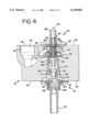
- FIG. 4is an enlarged cross sectional view of the modulating thermostat taken along the line 4--4 of FIG. 3;
- FIG. 5is an exploded isometric view of the modulating thermostat
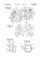
- FIG. 6is an isometric view of a cross section of the body of the modulating thermostat taken along the compound line 6--6 of FIG. 3;
- FIG. 7is a diagram illustrating steps in the method for machining the body of the modulating thermostat
- FIG. 8is an enlarged side view of an adjustment sleeve assembly of the modulating thermostat.
- FIG. 9is a further enlarged cross sectional view of the adjustment sleeve taken along the line 9--9 of FIG. 8 illustrating deformation of the sleeve during assembly of the modulating thermostat.
- FIGS. 1-3there is illustrated a modulating thermostat generally designated as 10 and constructed in accordance with the principles of the present invention.
- the thermostat 10is used with a gas oven 12, schematically shown in broken lines, having a main oven burner 14, a pilot burner 16 and a temperature sensing device 18.
- the useroperates the thermostat 10 to an on position to admit gas to both the main and pilot burners 14 and 16.
- the userignites the gas flowing from the main burner 14 and the gas flowing from the pilot burner 16 is ignited by flame at the main burner 14.
- the pilot burner 16is able to reignite gas flowing from the main burner 14 if the flame is inadvertently extinguished by oven door slam or the like.
- the thermostat 10functions to modulate gas flow to the main burner 14 in order to maintain a set oven temperature.
- the thermostat 10includes a body 20 having an inlet port 22 for receiving gaseous fuel from a gas supply such as a gas manifold 24 (FIG. 2), a main outlet port 26 for supplying gas through a conduit 28 to the main burner 14 and a pilot outlet port 30 for supplying gas through a conduit 32 to the pilot burner 16.
- a gas supplysuch as a gas manifold 24 (FIG. 2)
- main outlet port 26for supplying gas through a conduit 28 to the main burner 14
- a pilot outlet port 30for supplying gas through a conduit 32 to the pilot burner 16.
- a valve stem 34carries a knob (not shown) with which the user rotates the stem 34 to operate the thermostat 10 to an off position in which no gas flows to the burners 14 and 16 or to one of a range of on positions in which an adjusted, constant flow of gas is supplied to the pilot burner 16, an adjusted, constant bypass flow of gas is supplied to the main burner 14 and the bypass flow is augmented by a modulated flow of gas to the main burner 14 for maintaining a set oven temperature corresponding to the rotational position of the valve stem 34.
- the body 20is preferably a machined aluminum casting and includes front and rear walls 36 and 38. As seen in FIGS. 4 and 6, a central supply passage 40 extends between the front and rear walls 36 and 38 along a major axis of the thermostat 10.
- a generally conical inlet section 42extends from the front wall 36 and an outlet section 44 extends from the rear wall 38.
- the inlet and outlet sections 42 and 44are separated by a valve seat 46.
- An inlet passage 48(FIG. 1) extending upward from a bottom wall 50 of the body 20 supplies gas from the inlet port 22 to the conical inlet section 42.
- a valve member 52 of a modulating valve assembly 54cooperates with the valve seat 46 to modulate flow from the inlet section 42 to the outlet section 44.
- a main passage 56 and a pilot passage 58extend between the front and rear walls 36 and 38, spaced from and at opposite sides of the supply passage 48.
- the main passage 56communicates with the main outlet port 26 at the rear wall 38, and includes a main mouth portion 60 at the front wall 36.
- the main passage 56includes an enlarged rear portion 62 (FIG. 4) extending forward from the main outlet port 26 and a smaller offset portion 64 (FIGS. 3 and 6) extending from the mouth portion 60 to the enlarged portion 62.
- the pilot passage 58communicates with the pilot outlet port 30 at the rear wall 38, and includes a pilot mouth portion 66 at the front wall 36.
- An outlet passage 68(FIG. 4) extends from the outlet section 44 of the supply passage 40 to the main passage 56.
- a manually operated valve assembly 70includes a conical valve plug 72 seated in the conical inlet section 42 of the supply passage 40.
- the valve plug 72blocks the inlet passage 48 and no gas is permitted to flow into the inlet section 42.
- an aperture 74 in the valve plug 72(FIG. 5) registers with the inlet passage and gas flows into the inlet section 42.
- a pilot feeder passage 76extends from the inset section 42 to the pilot passage 58 so that when gas enters the inlet section 42, gas flows through the pilot feeder passage 76 and the pilot passage 58 to the pilot outlet port 30.
- a pilot flow adjustment sleeve assembly 78is used to adjust the pilot flow to meet burner and fuel requirements.
- a bypass flow of gasis also supplied continuously to the main burner 14 when the thermostat 10 is operated to any on position.
- a bypass feeder passage 80extends from the inset section 42 to the main passage 56 so that when gas enters the inlet section 42, gas flows through the bypass feeder passage 80 and the main passage 56 to the main outlet port 26.
- a bypass flow adjustment sleeve assembly 82is used to adjust the bypass flow to meet burner and fuel requirements and assure that a minimum flow needed to maintain stable combustion is always present at the main burner 14 when the thermostat 10 is in any on position.
- the body 20 of the thermostat 10is formed by casting of the aluminum body 20 and subsequent machining.
- the inlet and outlet passages 48 and 68 as well as the pilot and bypass feeder passages 76 and 80are preferably drilled into the body 20.
- FIG. 7provides a diagrammatic illustration of how the outlet passage 68 and the feeder passages 76 and 80 are formed. This illustration is illustrative and not physically accurate in that the passages 68, 76 and 80 do not lie in a common plane within the body 20.
- the actual position and orientation of the feeder passages 56 and 58are in FIG. 6.
- the outlet passage 68is drilled along a path indicated by the broken lines 84 in FIG. 7, and the inlet passage 48 (seen only in FIG. 1) can be drilled along a path extending upwardly from the bottom side wall 50.
- the pilot feeder passage 76is drilled along a path indicated by the broken lines 86 in FIG. 7. This path enters the body 20 at the pilot passage mouth portion 66 and extends at an angle to the inlet section 42 where it emerges inside the valve seat 46.
- the bypass feeder passageis drilled along a path indicated by the broken lines 88 and enters the body 20 at the main passage mouth portion 60 and extends at an angle to the inlet section 42, where it emerges within the valve seat 46.
- the adjustment sleeve assemblies 78 and 82may be identical, and the assembly 78 is seen in FIG. 8.
- a sleeve member 90includes a slotted and flanged head 92 and a projecting tubular portion 94.
- An O-ring 96is placed beneath the head 92.
- a flow adjustment opening 98is formed in the tubular portion 94.
- the openings 98 of the adjustment sleeve assemblies 78 and 82are axially located so that when the sleeve assemblies are installed in the mouth portions 60 and 66, the openings can be aligned with the feeder passages 76 and 78.
- the sleeve members 90are preferably formed of brass, a metal that is substantially softer than the aluminum of which the body 20 is made.
- Each sleeve assembly 78 and 82is initially inserted into the corresponding mouth portion 60 or 66 with the opening 98 facing away from, or generally diametrically opposed to, the corresponding feeder passage 76 or 80. Then, with the head 92 supported against axial movement, a tool is inserted into the opposite end of the corresponding main or pilot passage 56 or 58. The tool is used to axially compress the tubular portion 94 in order to deform the tubular portion 94 and create a tight interference fit between the tubular portion 94 and the surrounding passage wall.
- the portion of the wall of the tubular portion 94 that overlies the feeder passage 76 or 80 during this deformationis slightly bulged outward into the feeder passage by the resulting axial compressive deformation.
- the resulting bulge 100is seen in FIG. 9 opposite the opening 98 in the region indicated by the reference lines 102.
- a bladed toolis used to rotate the sleeve member 90 to bring the opening 98 into a desired amount of overlap with the feeder passage 76 or 80.
- the bulge 100tends to resiliently bias the sleeve member 90 to the side within the corresponding passage mouth and urges the tubular portion 94 toward the feeder passage to ensure a tight seal of the tubular portion 94 against the wall of the passage 56 or 58 to prevent leakage around the feeder passage opening.
- the stem 34is a hollow tubular body with its inner end swaged to a washer 104.
- a spring 106biases the washer 104 forward against a bushing 108 attached to a front plate 110.
- the washer 104has a radially inwardly extending tang 112 (FIG. 5) that drivingly engages a drive slot 114 at the forward end of the valve plug 72 (FIG. 4) so that rotation of the stem 34 results in rotation of the valve plug 72.
- An outwardly extending tang 116 (FIG. 5) of the washer 104cooperates with limit abutments 118 on the front plate 110 to limit rotation of the stem 34 to about 270 degrees.
- the valve plugIn one limit position, the valve plug is in the off position, and blocks the inlet passage 48 to prevent the flow of gas into the inlet section 42 of the supply passage 40.
- the stem 34can be rotated from the off position to any of a range of on positions in which the aperture 74 admits gas to the supply passage 42 and, by way of the feeder passages 76 and 79, to the pilot and main outlet ports 30 and 26.
- the range of on positionscorresponds to a range of oven temperatures to be maintained by operation of the modulating valve assembly 54.
- the temperature sensing device 18is preferably a fluid filled bulb communicating through a capillary tube 120 with a diaphragm assembly 122 that expands as oven temperature increases.
- the capillary tube 120terminates in a stud 124 attached to a back plate 125 by a nut 126.
- the interior of the stud 124communicates with the interior of the diaphragm assembly 122, and a nib 128 having a threaded shank 130 is attached to the front of the diaphragm assembly 122.
- a spindle 132is threaded onto the shank 130 and the valve member 52 is captured against the spindle 132 by an 0-ring 134, a cup member 136 and a spring 138.
- the expansion of the diaphragm assembly 122moves the nib 128, spindle 132 and the valve member 52 forward toward the valve seat 46, decreasing gas flow through the modulating valve assembly from the inlet section 42 to the outlet section 44 of the supply passage 40.
- Rotation of the stem 34sets the thermostat 10 to heat the oven 12 to a selected temperature. Engagement of the washer tang 112 with the drive slot 114 permits the stem 34 to rotate the valve plug 72.
- a bushing 140 fixed to the valve plug 72rotationally supports a sleeve 142 having a slotted head 144 at its forward end.
- a drive pin 146is transversely supported at the rearward end of the sleeve 142. The drive pin 146 engages an elongated axial drive slot 148 in the forward end of the spindle 132.
- Rotation of the stem 34 and valve plug 72causes the drive pin 144 to rotate the spindle 132 and the spindle is threaded forwardly or rearwardly along the shank 130 to decrease or increase the axial spacing between the valve member 52 and the diaphragm assembly 122. This varies the oven temperature corresponding to a given spacing between the valve member 52 and valve seat 46, thus setting a predetermined temperature to be maintained by the thermostat 10.
- the thermostat 10is calibrated in order to correct for manufacturing tolerances and other variables and to assure that the relation between stem position and set oven temperatures is correct.
- the thermostat 10is calibrated by inserting a slotted tool into the hollow stem 34 and engaging the slotted head 144.
- the sleeve 142is rotated while the stem 34 and valve plug 72 are stationary. This adjusts the axial position of the spindle 132 along the shank 130 so that in any given on position of the shank 34 and valve plug 72 the set oven temperature corresponds to the temperature desired by the user and indicated for example by indicia on a knob carried by the stem 34.
- Calibrationis effected using the same threaded coupling that is used to set the operating temperature, resulting in a simple and inexpensive arrangement.
- the thermostat 10can be calibrated after installation if needed because access to the back of the thermostat 10 is not required.
Landscapes
- Engineering & Computer Science (AREA)
- Chemical & Material Sciences (AREA)
- Combustion & Propulsion (AREA)
- Mechanical Engineering (AREA)
- General Engineering & Computer Science (AREA)
- Control Of Combustion (AREA)
Abstract
Description
Claims (10)
Priority Applications (1)
| Application Number | Priority Date | Filing Date | Title |
|---|---|---|---|
| US09/182,294US6149065A (en) | 1998-10-28 | 1998-10-28 | Modulating thermostat for gas oven burner |
Applications Claiming Priority (1)
| Application Number | Priority Date | Filing Date | Title |
|---|---|---|---|
| US09/182,294US6149065A (en) | 1998-10-28 | 1998-10-28 | Modulating thermostat for gas oven burner |
Publications (1)
| Publication Number | Publication Date |
|---|---|
| US6149065Atrue US6149065A (en) | 2000-11-21 |
Family
ID=22667851
Family Applications (1)
| Application Number | Title | Priority Date | Filing Date |
|---|---|---|---|
| US09/182,294Expired - Fee RelatedUS6149065A (en) | 1998-10-28 | 1998-10-28 | Modulating thermostat for gas oven burner |
Country Status (1)
| Country | Link |
|---|---|
| US (1) | US6149065A (en) |
Cited By (70)
| Publication number | Priority date | Publication date | Assignee | Title |
|---|---|---|---|---|
| WO2002054875A1 (en)* | 2000-11-17 | 2002-07-18 | Middleby Corporation | Conveyor oven with modulated gas flow |
| US6481433B1 (en)* | 2000-11-17 | 2002-11-19 | Middleby Marshall Incorporated | Conveyor oven having an energy management system for a modulated gas flow |
| US20040106710A1 (en)* | 2002-08-22 | 2004-06-03 | Klausjoerg Klein | Cathodic electrodeposition coating agents containing bismuth salts together with yttrium and/or neodymium compounds, production and use thereof |
| US6851621B1 (en) | 2003-08-18 | 2005-02-08 | Honeywell International Inc. | PDA diagnosis of thermostats |
| US20050040250A1 (en)* | 2003-08-18 | 2005-02-24 | Wruck Richard A. | Transfer of controller customizations |
| US7055759B2 (en) | 2003-08-18 | 2006-06-06 | Honeywell International Inc. | PDA configuration of thermostats |
| US7083109B2 (en) | 2003-08-18 | 2006-08-01 | Honeywell International Inc. | Thermostat having modulated and non-modulated provisions |
| US7320110B2 (en) | 2000-11-03 | 2008-01-15 | Honeywell International Inc. | Multiple language user interface for thermal comfort controller |
| US20090020019A1 (en)* | 2007-06-21 | 2009-01-22 | Potdar Medhavin P | Food cooking device with combination valve |
| USD596963S1 (en) | 2008-08-18 | 2009-07-28 | Honeywell International Inc. | Environmental controller housing |
| USD596964S1 (en) | 2008-09-05 | 2009-07-28 | Honeywell International Inc. | Thermostat housing |
| US7584897B2 (en) | 2005-03-31 | 2009-09-08 | Honeywell International Inc. | Controller system user interface |
| US7861941B2 (en) | 2005-02-28 | 2011-01-04 | Honeywell International Inc. | Automatic thermostat schedule/program selector system |
| US8032254B2 (en) | 2007-11-30 | 2011-10-04 | Honeywell International Inc. | Method and apparatus for configuring an HVAC controller |
| US8087407B2 (en) | 2004-03-23 | 2012-01-03 | Middleby Corporation | Conveyor oven apparatus and method |
| US8167216B2 (en) | 2007-11-30 | 2012-05-01 | Honeywell International Inc. | User setup for an HVAC remote control unit |
| US8232860B2 (en) | 2005-10-21 | 2012-07-31 | Honeywell International Inc. | RFID reader for facility access control and authorization |
| US8351350B2 (en) | 2007-05-28 | 2013-01-08 | Honeywell International Inc. | Systems and methods for configuring access control devices |
| USD678084S1 (en) | 2012-06-05 | 2013-03-19 | Honeywell International Inc. | Thermostat housing |
| US8598982B2 (en) | 2007-05-28 | 2013-12-03 | Honeywell International Inc. | Systems and methods for commissioning access control devices |
| US8707414B2 (en) | 2010-01-07 | 2014-04-22 | Honeywell International Inc. | Systems and methods for location aware access control management |
| US8783243B2 (en) | 2010-10-25 | 2014-07-22 | General Electric Company | Lockout system for surface burners of a cooking appliance |
| US8787725B2 (en) | 2010-11-11 | 2014-07-22 | Honeywell International Inc. | Systems and methods for managing video data |
| US8839714B2 (en) | 2009-08-28 | 2014-09-23 | The Middleby Corporation | Apparatus and method for controlling a conveyor oven |
| US8878931B2 (en) | 2009-03-04 | 2014-11-04 | Honeywell International Inc. | Systems and methods for managing video data |
| US8892223B2 (en) | 2011-09-07 | 2014-11-18 | Honeywell International Inc. | HVAC controller including user interaction log |
| US8902071B2 (en) | 2011-12-14 | 2014-12-02 | Honeywell International Inc. | HVAC controller with HVAC system fault detection |
| USD720633S1 (en) | 2013-10-25 | 2015-01-06 | Honeywell International Inc. | Thermostat |
| US8950687B2 (en) | 2010-09-21 | 2015-02-10 | Honeywell International Inc. | Remote control of an HVAC system that uses a common temperature setpoint for both heat and cool modes |
| US9002523B2 (en) | 2011-12-14 | 2015-04-07 | Honeywell International Inc. | HVAC controller with diagnostic alerts |
| US9002481B2 (en) | 2010-07-14 | 2015-04-07 | Honeywell International Inc. | Building controllers with local and global parameters |
| US9019070B2 (en) | 2009-03-19 | 2015-04-28 | Honeywell International Inc. | Systems and methods for managing access control devices |
| US9206993B2 (en) | 2011-12-14 | 2015-12-08 | Honeywell International Inc. | HVAC controller with utility saver switch diagnostic feature |
| US9280365B2 (en) | 2009-12-17 | 2016-03-08 | Honeywell International Inc. | Systems and methods for managing configuration data at disconnected remote devices |
| US9344684B2 (en) | 2011-08-05 | 2016-05-17 | Honeywell International Inc. | Systems and methods configured to enable content sharing between client terminals of a digital video management system |
| US9366448B2 (en) | 2011-06-20 | 2016-06-14 | Honeywell International Inc. | Method and apparatus for configuring a filter change notification of an HVAC controller |
| US9442500B2 (en) | 2012-03-08 | 2016-09-13 | Honeywell International Inc. | Systems and methods for associating wireless devices of an HVAC system |
| US9471069B2 (en) | 2003-12-02 | 2016-10-18 | Honeywell International Inc | Configurable thermostat for controlling HVAC system |
| US9477239B2 (en) | 2012-07-26 | 2016-10-25 | Honeywell International Inc. | HVAC controller with wireless network based occupancy detection and control |
| US9488994B2 (en) | 2012-03-29 | 2016-11-08 | Honeywell International Inc. | Method and system for configuring wireless sensors in an HVAC system |
| US20160353756A1 (en)* | 2015-06-08 | 2016-12-08 | Masterbuilt Manufacturing, Inc. | Stand-Alone Gas-Fired Smoker with Mechanical Temperature Control |
| US9584119B2 (en) | 2013-04-23 | 2017-02-28 | Honeywell International Inc. | Triac or bypass circuit and MOSFET power steal combination |
| US9585400B2 (en) | 2004-03-23 | 2017-03-07 | The Middleby Corporation | Conveyor oven apparatus and method |
| US9628074B2 (en) | 2014-06-19 | 2017-04-18 | Honeywell International Inc. | Bypass switch for in-line power steal |
| US9673811B2 (en) | 2013-11-22 | 2017-06-06 | Honeywell International Inc. | Low power consumption AC load switches |
| US9683749B2 (en) | 2014-07-11 | 2017-06-20 | Honeywell International Inc. | Multiple heatsink cooling system for a line voltage thermostat |
| US9704313B2 (en) | 2008-09-30 | 2017-07-11 | Honeywell International Inc. | Systems and methods for interacting with access control devices |
| US9806705B2 (en) | 2013-04-23 | 2017-10-31 | Honeywell International Inc. | Active triac triggering circuit |
| US9857091B2 (en) | 2013-11-22 | 2018-01-02 | Honeywell International Inc. | Thermostat circuitry to control power usage |
| GB2516778B (en)* | 2012-04-24 | 2018-01-10 | Groundhog (Uk) Ltd | Thermal treatment system |
| US9894261B2 (en) | 2011-06-24 | 2018-02-13 | Honeywell International Inc. | Systems and methods for presenting digital video management system information via a user-customizable hierarchical tree interface |
| US9983244B2 (en) | 2013-06-28 | 2018-05-29 | Honeywell International Inc. | Power transformation system with characterization |
| US10024548B2 (en) | 2003-02-21 | 2018-07-17 | The Middleby Corporation | Self-cleaning oven |
| US10038872B2 (en) | 2011-08-05 | 2018-07-31 | Honeywell International Inc. | Systems and methods for managing video data |
| US10082312B2 (en) | 2013-04-30 | 2018-09-25 | Honeywell International Inc. | HVAC controller with multi-region display and guided setup |
| US10094585B2 (en) | 2013-01-25 | 2018-10-09 | Honeywell International Inc. | Auto test for delta T diagnostics in an HVAC system |
| US10139843B2 (en) | 2012-02-22 | 2018-11-27 | Honeywell International Inc. | Wireless thermostatic controlled electric heating system |
| US10302322B2 (en) | 2016-07-22 | 2019-05-28 | Ademco Inc. | Triage of initial schedule setup for an HVAC controller |
| US10362273B2 (en) | 2011-08-05 | 2019-07-23 | Honeywell International Inc. | Systems and methods for managing video data |
| US10436977B2 (en) | 2013-12-11 | 2019-10-08 | Ademco Inc. | Building automation system setup using a remote control device |
| US10452084B2 (en) | 2012-03-14 | 2019-10-22 | Ademco Inc. | Operation of building control via remote device |
| US10488062B2 (en) | 2016-07-22 | 2019-11-26 | Ademco Inc. | Geofence plus schedule for a building controller |
| US10523903B2 (en) | 2013-10-30 | 2019-12-31 | Honeywell International Inc. | Computer implemented systems frameworks and methods configured for enabling review of incident data |
| US10533761B2 (en) | 2011-12-14 | 2020-01-14 | Ademco Inc. | HVAC controller with fault sensitivity |
| US10534383B2 (en) | 2011-12-15 | 2020-01-14 | Ademco Inc. | HVAC controller with performance log |
| US10624241B1 (en)* | 2015-10-06 | 2020-04-14 | Amazon Technologies, Inc. | Rack mountable thermal regulation system |
| US10747243B2 (en) | 2011-12-14 | 2020-08-18 | Ademco Inc. | HVAC controller with HVAC system failure detection |
| US10811892B2 (en) | 2013-06-28 | 2020-10-20 | Ademco Inc. | Source management for a power transformation system |
| US10928087B2 (en) | 2012-07-26 | 2021-02-23 | Ademco Inc. | Method of associating an HVAC controller with an external web service |
| US11054448B2 (en) | 2013-06-28 | 2021-07-06 | Ademco Inc. | Power transformation self characterization mode |
Citations (3)
| Publication number | Priority date | Publication date | Assignee | Title |
|---|---|---|---|---|
| US2245060A (en)* | 1937-11-08 | 1941-06-10 | Wilcolator Co | Temperature control for gas ranges |
| US3542290A (en)* | 1968-10-28 | 1970-11-24 | Aurora Corp | Thermostatic gas valve |
| US4765536A (en)* | 1987-04-14 | 1988-08-23 | Eaton Corporation | Thermostatic control valve assembly for fuel gas burner |
- 1998
- 1998-10-28USUS09/182,294patent/US6149065A/ennot_activeExpired - Fee Related
Patent Citations (3)
| Publication number | Priority date | Publication date | Assignee | Title |
|---|---|---|---|---|
| US2245060A (en)* | 1937-11-08 | 1941-06-10 | Wilcolator Co | Temperature control for gas ranges |
| US3542290A (en)* | 1968-10-28 | 1970-11-24 | Aurora Corp | Thermostatic gas valve |
| US4765536A (en)* | 1987-04-14 | 1988-08-23 | Eaton Corporation | Thermostatic control valve assembly for fuel gas burner |
Cited By (123)
| Publication number | Priority date | Publication date | Assignee | Title |
|---|---|---|---|---|
| US7320110B2 (en) | 2000-11-03 | 2008-01-15 | Honeywell International Inc. | Multiple language user interface for thermal comfort controller |
| US6481433B1 (en)* | 2000-11-17 | 2002-11-19 | Middleby Marshall Incorporated | Conveyor oven having an energy management system for a modulated gas flow |
| US6684875B1 (en)* | 2000-11-17 | 2004-02-03 | Middleby Corporation | Conveyor oven with modulated gas flow |
| WO2002054875A1 (en)* | 2000-11-17 | 2002-07-18 | Middleby Corporation | Conveyor oven with modulated gas flow |
| USRE43035E1 (en) | 2000-11-17 | 2011-12-20 | Middeby Marshall Incorporated | Conveyor oven having an energy management system for a modulated gas flow |
| WO2002102164A1 (en)* | 2001-06-18 | 2002-12-27 | Middleby Marshall Incorporated | Conveyor oven having an energy management system for a modulated gas flow |
| US20040106710A1 (en)* | 2002-08-22 | 2004-06-03 | Klausjoerg Klein | Cathodic electrodeposition coating agents containing bismuth salts together with yttrium and/or neodymium compounds, production and use thereof |
| US10024548B2 (en) | 2003-02-21 | 2018-07-17 | The Middleby Corporation | Self-cleaning oven |
| US10036558B2 (en) | 2003-02-21 | 2018-07-31 | The Middleby Corporation | Self-cleaning oven |
| US20050040250A1 (en)* | 2003-08-18 | 2005-02-24 | Wruck Richard A. | Transfer of controller customizations |
| US7222800B2 (en) | 2003-08-18 | 2007-05-29 | Honeywell International Inc. | Controller customization management system |
| US7083109B2 (en) | 2003-08-18 | 2006-08-01 | Honeywell International Inc. | Thermostat having modulated and non-modulated provisions |
| US7055759B2 (en) | 2003-08-18 | 2006-06-06 | Honeywell International Inc. | PDA configuration of thermostats |
| US20070114291A1 (en)* | 2003-08-18 | 2007-05-24 | Honeywell International Inc. | Thermostat having modulated and non-modulated provisions |
| US7565813B2 (en) | 2003-08-18 | 2009-07-28 | Honeywell International Inc. | Thermostat having modulated and non-modulated provisions |
| US6851621B1 (en) | 2003-08-18 | 2005-02-08 | Honeywell International Inc. | PDA diagnosis of thermostats |
| US20050040249A1 (en)* | 2003-08-18 | 2005-02-24 | Wacker Paul C. | Pda diagnosis of thermostats |
| US10579078B2 (en) | 2003-12-02 | 2020-03-03 | Ademco Inc. | Interview programming for an HVAC controller |
| US9733653B2 (en) | 2003-12-02 | 2017-08-15 | Honeywell International Inc. | Interview programming for an HVAC controller |
| US9471069B2 (en) | 2003-12-02 | 2016-10-18 | Honeywell International Inc | Configurable thermostat for controlling HVAC system |
| US10039289B2 (en) | 2004-03-23 | 2018-08-07 | The Middleby Corporation | Conveyor oven apparatus and method |
| US8281779B2 (en) | 2004-03-23 | 2012-10-09 | Middleby Corporation | Conveyor oven apparatus and method |
| US9585400B2 (en) | 2004-03-23 | 2017-03-07 | The Middleby Corporation | Conveyor oven apparatus and method |
| US9585401B2 (en) | 2004-03-23 | 2017-03-07 | The Middleby Corporation | Conveyor oven apparatus and method |
| US8087407B2 (en) | 2004-03-23 | 2012-01-03 | Middleby Corporation | Conveyor oven apparatus and method |
| US10842156B2 (en) | 2004-03-23 | 2020-11-24 | The Middleby Corporation | Conveyor oven apparatus and method |
| US8839779B2 (en) | 2004-03-23 | 2014-09-23 | Middleby Corporation | Conveyor oven apparatus and method |
| US8371285B2 (en) | 2004-03-23 | 2013-02-12 | Middleby Corporation | Conveyor oven apparatus and method |
| US7861941B2 (en) | 2005-02-28 | 2011-01-04 | Honeywell International Inc. | Automatic thermostat schedule/program selector system |
| US8083154B2 (en) | 2005-03-31 | 2011-12-27 | Honeywell International Inc. | Controller system user interface |
| US7641126B2 (en) | 2005-03-31 | 2010-01-05 | Honeywell International Inc. | Controller system user interface |
| US7584897B2 (en) | 2005-03-31 | 2009-09-08 | Honeywell International Inc. | Controller system user interface |
| US8232860B2 (en) | 2005-10-21 | 2012-07-31 | Honeywell International Inc. | RFID reader for facility access control and authorization |
| US8941464B2 (en) | 2005-10-21 | 2015-01-27 | Honeywell International Inc. | Authorization system and a method of authorization |
| US8351350B2 (en) | 2007-05-28 | 2013-01-08 | Honeywell International Inc. | Systems and methods for configuring access control devices |
| US8598982B2 (en) | 2007-05-28 | 2013-12-03 | Honeywell International Inc. | Systems and methods for commissioning access control devices |
| US20090020019A1 (en)* | 2007-06-21 | 2009-01-22 | Potdar Medhavin P | Food cooking device with combination valve |
| US8167216B2 (en) | 2007-11-30 | 2012-05-01 | Honeywell International Inc. | User setup for an HVAC remote control unit |
| US8224491B2 (en) | 2007-11-30 | 2012-07-17 | Honeywell International Inc. | Portable wireless remote control unit for use with zoned HVAC system |
| US8346396B2 (en) | 2007-11-30 | 2013-01-01 | Honeywell International Inc. | HVAC controller with parameter clustering |
| US9765983B2 (en) | 2007-11-30 | 2017-09-19 | Honeywell International Inc. | User setup for an HVAC remote control unit |
| US8087593B2 (en) | 2007-11-30 | 2012-01-03 | Honeywell International Inc. | HVAC controller with quick select feature |
| US9151510B2 (en) | 2007-11-30 | 2015-10-06 | Honeywell International Inc. | Display for HVAC systems in remote control units |
| US8032254B2 (en) | 2007-11-30 | 2011-10-04 | Honeywell International Inc. | Method and apparatus for configuring an HVAC controller |
| US8876013B2 (en) | 2007-11-30 | 2014-11-04 | Honeywell International Inc. | HVAC controller that selectively replaces operating information on a display with system status information |
| US8768521B2 (en) | 2007-11-30 | 2014-07-01 | Honeywell International Inc. | HVAC controller with parameter clustering |
| US8731723B2 (en) | 2007-11-30 | 2014-05-20 | Honeywell International Inc. | HVAC controller having a parameter adjustment element with a qualitative indicator |
| US8091796B2 (en) | 2007-11-30 | 2012-01-10 | Honeywell International Inc. | HVAC controller that selectively replaces operating information on a display with system status information |
| US9964321B2 (en) | 2007-11-30 | 2018-05-08 | Honeywell International Inc. | HVAC controller having a parameter adjustment element with a qualitative indicator |
| US8387892B2 (en) | 2007-11-30 | 2013-03-05 | Honeywell International Inc. | Remote control for use in zoned and non-zoned HVAC systems |
| USD596963S1 (en) | 2008-08-18 | 2009-07-28 | Honeywell International Inc. | Environmental controller housing |
| USD596964S1 (en) | 2008-09-05 | 2009-07-28 | Honeywell International Inc. | Thermostat housing |
| US9704313B2 (en) | 2008-09-30 | 2017-07-11 | Honeywell International Inc. | Systems and methods for interacting with access control devices |
| US8878931B2 (en) | 2009-03-04 | 2014-11-04 | Honeywell International Inc. | Systems and methods for managing video data |
| US9019070B2 (en) | 2009-03-19 | 2015-04-28 | Honeywell International Inc. | Systems and methods for managing access control devices |
| US10362898B2 (en) | 2009-08-28 | 2019-07-30 | The Middleby Corporation | Apparatus and method for controlling a conveyor oven |
| US8839714B2 (en) | 2009-08-28 | 2014-09-23 | The Middleby Corporation | Apparatus and method for controlling a conveyor oven |
| US9609981B2 (en) | 2009-08-28 | 2017-04-04 | The Middleby Corporation | Apparatus and method for controlling a conveyor oven |
| US9280365B2 (en) | 2009-12-17 | 2016-03-08 | Honeywell International Inc. | Systems and methods for managing configuration data at disconnected remote devices |
| US8707414B2 (en) | 2010-01-07 | 2014-04-22 | Honeywell International Inc. | Systems and methods for location aware access control management |
| US9002481B2 (en) | 2010-07-14 | 2015-04-07 | Honeywell International Inc. | Building controllers with local and global parameters |
| US10422543B2 (en) | 2010-09-21 | 2019-09-24 | Ademco Inc. | Remote control of an HVAC system that uses a common temperature setpoint for both heat and cool modes |
| US9816719B2 (en) | 2010-09-21 | 2017-11-14 | Honeywell International Inc. | Remote control of an HVAC system that uses a common temperature setpoint for both heat and cool modes |
| US8950687B2 (en) | 2010-09-21 | 2015-02-10 | Honeywell International Inc. | Remote control of an HVAC system that uses a common temperature setpoint for both heat and cool modes |
| US8783243B2 (en) | 2010-10-25 | 2014-07-22 | General Electric Company | Lockout system for surface burners of a cooking appliance |
| US8787725B2 (en) | 2010-11-11 | 2014-07-22 | Honeywell International Inc. | Systems and methods for managing video data |
| US9366448B2 (en) | 2011-06-20 | 2016-06-14 | Honeywell International Inc. | Method and apparatus for configuring a filter change notification of an HVAC controller |
| US9894261B2 (en) | 2011-06-24 | 2018-02-13 | Honeywell International Inc. | Systems and methods for presenting digital video management system information via a user-customizable hierarchical tree interface |
| US10362273B2 (en) | 2011-08-05 | 2019-07-23 | Honeywell International Inc. | Systems and methods for managing video data |
| US10038872B2 (en) | 2011-08-05 | 2018-07-31 | Honeywell International Inc. | Systems and methods for managing video data |
| US9344684B2 (en) | 2011-08-05 | 2016-05-17 | Honeywell International Inc. | Systems and methods configured to enable content sharing between client terminals of a digital video management system |
| US10863143B2 (en) | 2011-08-05 | 2020-12-08 | Honeywell International Inc. | Systems and methods for managing video data |
| US8892223B2 (en) | 2011-09-07 | 2014-11-18 | Honeywell International Inc. | HVAC controller including user interaction log |
| US9157647B2 (en) | 2011-09-07 | 2015-10-13 | Honeywell International Inc. | HVAC controller including user interaction log |
| US8902071B2 (en) | 2011-12-14 | 2014-12-02 | Honeywell International Inc. | HVAC controller with HVAC system fault detection |
| US10747243B2 (en) | 2011-12-14 | 2020-08-18 | Ademco Inc. | HVAC controller with HVAC system failure detection |
| US9206993B2 (en) | 2011-12-14 | 2015-12-08 | Honeywell International Inc. | HVAC controller with utility saver switch diagnostic feature |
| US9002523B2 (en) | 2011-12-14 | 2015-04-07 | Honeywell International Inc. | HVAC controller with diagnostic alerts |
| US10533761B2 (en) | 2011-12-14 | 2020-01-14 | Ademco Inc. | HVAC controller with fault sensitivity |
| US10534383B2 (en) | 2011-12-15 | 2020-01-14 | Ademco Inc. | HVAC controller with performance log |
| US10139843B2 (en) | 2012-02-22 | 2018-11-27 | Honeywell International Inc. | Wireless thermostatic controlled electric heating system |
| US9442500B2 (en) | 2012-03-08 | 2016-09-13 | Honeywell International Inc. | Systems and methods for associating wireless devices of an HVAC system |
| US10452084B2 (en) | 2012-03-14 | 2019-10-22 | Ademco Inc. | Operation of building control via remote device |
| US10635119B2 (en) | 2012-03-29 | 2020-04-28 | Ademco Inc. | Method and system for configuring wireless sensors in an HVAC system |
| US9971364B2 (en) | 2012-03-29 | 2018-05-15 | Honeywell International Inc. | Method and system for configuring wireless sensors in an HVAC system |
| US9488994B2 (en) | 2012-03-29 | 2016-11-08 | Honeywell International Inc. | Method and system for configuring wireless sensors in an HVAC system |
| GB2516778B (en)* | 2012-04-24 | 2018-01-10 | Groundhog (Uk) Ltd | Thermal treatment system |
| USD678084S1 (en) | 2012-06-05 | 2013-03-19 | Honeywell International Inc. | Thermostat housing |
| US10613555B2 (en) | 2012-07-26 | 2020-04-07 | Ademco Inc. | HVAC controller with wireless network based occupancy detection and control |
| US10133283B2 (en) | 2012-07-26 | 2018-11-20 | Honeywell International Inc. | HVAC controller with wireless network based occupancy detection and control |
| US9477239B2 (en) | 2012-07-26 | 2016-10-25 | Honeywell International Inc. | HVAC controller with wireless network based occupancy detection and control |
| US11493224B2 (en) | 2012-07-26 | 2022-11-08 | Ademco Inc. | Method of associating an HVAC controller with an external web service |
| US10928087B2 (en) | 2012-07-26 | 2021-02-23 | Ademco Inc. | Method of associating an HVAC controller with an external web service |
| US10094585B2 (en) | 2013-01-25 | 2018-10-09 | Honeywell International Inc. | Auto test for delta T diagnostics in an HVAC system |
| US9584119B2 (en) | 2013-04-23 | 2017-02-28 | Honeywell International Inc. | Triac or bypass circuit and MOSFET power steal combination |
| US9806705B2 (en) | 2013-04-23 | 2017-10-31 | Honeywell International Inc. | Active triac triggering circuit |
| US10396770B2 (en) | 2013-04-23 | 2019-08-27 | Ademco Inc. | Active triac triggering circuit |
| US10404253B2 (en) | 2013-04-23 | 2019-09-03 | Ademco Inc. | Triac or bypass circuit and MOSFET power steal combination |
| US10852025B2 (en) | 2013-04-30 | 2020-12-01 | Ademco Inc. | HVAC controller with fixed segment display having fixed segment icons and animation |
| US10082312B2 (en) | 2013-04-30 | 2018-09-25 | Honeywell International Inc. | HVAC controller with multi-region display and guided setup |
| US10811892B2 (en) | 2013-06-28 | 2020-10-20 | Ademco Inc. | Source management for a power transformation system |
| US11054448B2 (en) | 2013-06-28 | 2021-07-06 | Ademco Inc. | Power transformation self characterization mode |
| US9983244B2 (en) | 2013-06-28 | 2018-05-29 | Honeywell International Inc. | Power transformation system with characterization |
| USD720633S1 (en) | 2013-10-25 | 2015-01-06 | Honeywell International Inc. | Thermostat |
| US10523903B2 (en) | 2013-10-30 | 2019-12-31 | Honeywell International Inc. | Computer implemented systems frameworks and methods configured for enabling review of incident data |
| US11523088B2 (en) | 2013-10-30 | 2022-12-06 | Honeywell Interntional Inc. | Computer implemented systems frameworks and methods configured for enabling review of incident data |
| US9673811B2 (en) | 2013-11-22 | 2017-06-06 | Honeywell International Inc. | Low power consumption AC load switches |
| US9857091B2 (en) | 2013-11-22 | 2018-01-02 | Honeywell International Inc. | Thermostat circuitry to control power usage |
| US10712718B2 (en) | 2013-12-11 | 2020-07-14 | Ademco Inc. | Building automation remote control device with in-application messaging |
| US10436977B2 (en) | 2013-12-11 | 2019-10-08 | Ademco Inc. | Building automation system setup using a remote control device |
| US10591877B2 (en) | 2013-12-11 | 2020-03-17 | Ademco Inc. | Building automation remote control device with an in-application tour |
| US10649418B2 (en) | 2013-12-11 | 2020-05-12 | Ademco Inc. | Building automation controller with configurable audio/visual cues |
| US10534331B2 (en) | 2013-12-11 | 2020-01-14 | Ademco Inc. | Building automation system with geo-fencing |
| US10768589B2 (en) | 2013-12-11 | 2020-09-08 | Ademco Inc. | Building automation system with geo-fencing |
| US10353411B2 (en) | 2014-06-19 | 2019-07-16 | Ademco Inc. | Bypass switch for in-line power steal |
| US9628074B2 (en) | 2014-06-19 | 2017-04-18 | Honeywell International Inc. | Bypass switch for in-line power steal |
| US9683749B2 (en) | 2014-07-11 | 2017-06-20 | Honeywell International Inc. | Multiple heatsink cooling system for a line voltage thermostat |
| US10088174B2 (en) | 2014-07-11 | 2018-10-02 | Honeywell International Inc. | Multiple heatsink cooling system for a line voltage thermostat |
| US20160353756A1 (en)* | 2015-06-08 | 2016-12-08 | Masterbuilt Manufacturing, Inc. | Stand-Alone Gas-Fired Smoker with Mechanical Temperature Control |
| US10021887B2 (en)* | 2015-06-08 | 2018-07-17 | Masterbuilt Manufacturing, Llc | Stand-alone gas-fired smoker with mechanical temperature control |
| US10624241B1 (en)* | 2015-10-06 | 2020-04-14 | Amazon Technologies, Inc. | Rack mountable thermal regulation system |
| US10488062B2 (en) | 2016-07-22 | 2019-11-26 | Ademco Inc. | Geofence plus schedule for a building controller |
| US10302322B2 (en) | 2016-07-22 | 2019-05-28 | Ademco Inc. | Triage of initial schedule setup for an HVAC controller |
Similar Documents
| Publication | Publication Date | Title |
|---|---|---|
| US6149065A (en) | Modulating thermostat for gas oven burner | |
| US6634351B2 (en) | Thermostatic gas valve with standing pilot flow | |
| US5566711A (en) | Combined control and regulating valve for liquids or gases | |
| JPH11351440A (en) | Thermal expansion valve and manufacture of the same | |
| US20020084068A1 (en) | Three-way heating system valve with heat exchanger pressure regulation | |
| GB2076127A (en) | Thermostatically controlled mixing valves for hot and cold water | |
| EP0657003B1 (en) | Valve with presetting facility | |
| US5836296A (en) | Manifold with integral burner control and oven control | |
| CN104884867B (en) | Thermostat | |
| MXPA03007809A (en) | Hot water temperature control valve system. | |
| US2302407A (en) | Temperature regulator | |
| GB2081874A (en) | Control systems for gas appliances | |
| US4303384A (en) | Flame failure device | |
| US3166248A (en) | Burner control system | |
| CA1280726C (en) | Thermostatic control valve assembly for fuel gas burner | |
| US1971801A (en) | Oven heat control | |
| KR980008408A (en) | Torch valve assembly | |
| US5067651A (en) | Fuel control device, fuel control system using the device and method of making the device | |
| US4108370A (en) | Fuel control system having by-pass means and parts therefor and the like | |
| US3398890A (en) | Fail-safe regulator for gas-oven burners | |
| US2245171A (en) | Regulating valve | |
| US5102039A (en) | Fuel control device and method of making the same | |
| US9423153B2 (en) | Unregulated integrated function gas valve for a water heater | |
| JP2003035473A (en) | Expansion valve unit | |
| US3701598A (en) | Flow control device with pressure regulation |
Legal Events
| Date | Code | Title | Description |
|---|---|---|---|
| AS | Assignment | Owner name:HARPER-WYMAN COMPANY, ILLINOIS Free format text:ASSIGNMENT OF ASSIGNORS INTEREST;ASSIGNORS:WHITE, DAVID B.;WHITE, CHARLES S.;REEL/FRAME:009666/0857 Effective date:19990105 | |
| AS | Assignment | Owner name:APPLIANCE CONTROLS GROUP, INC., ILLINOIS Free format text:ASSIGNMENT OF ASSIGNORS INTEREST;ASSIGNOR:HARPER-WYMAN COMPANY;REEL/FRAME:013067/0292 Effective date:20020531 | |
| AS | Assignment | Owner name:TRANSAMERICA BUSINESS CAPITAL CORPORATION, AS AGEN Free format text:SECURITY INTEREST;ASSIGNOR:APPLIANCE CONTROLS GROUP, INC.;REEL/FRAME:013081/0647 Effective date:20020621 | |
| AS | Assignment | Owner name:HILCO CAPITAL LP, ILLINOIS Free format text:ASSIGNMENT OF ASSIGNORS INTEREST;ASSIGNOR:APPLIANCE CONTROLS GROUP, INC.;REEL/FRAME:013146/0196 Effective date:20020726 Owner name:HILCO CAPITAL LP, ILLINOIS Free format text:SECURITY AGREEMENT;ASSIGNOR:APPLIANCE CONTROLS GROUP, INC.;REEL/FRAME:013146/0180 Effective date:20020726 | |
| REMI | Maintenance fee reminder mailed | ||
| AS | Assignment | Owner name:BURNER SYSTEMS INTERNATIONAL, INC., TENNESSEE Free format text:ASSIGNMENT OF ASSIGNORS INTEREST;ASSIGNORS:APPLIANCE CONTROLS GROUP HOLDINGS, INC.;APPLIANCE CONTROLS GROUP, INC.;REEL/FRAME:014943/0183 Effective date:20040726 | |
| AS | Assignment | Owner name:JPMORGAN CHASE BANK, NEW YORK Free format text:SECURITY AGREEMENT;ASSIGNOR:BURNER SYSTEMS INTERNATIONAL, INC.;REEL/FRAME:014964/0774 Effective date:20040726 | |
| AS | Assignment | Owner name:APPLIANCE CONTROLS GROUP, INC., ILLINOIS Free format text:ASSIGNMENT OF ASSIGNORS INTEREST;ASSIGNOR:HILCO CAPITAL, LP;REEL/FRAME:015676/0400 Effective date:20040725 Owner name:APPLIANCE CONTROLS GROUP, INC., ILLINOIS Free format text:RELEASE OF SECURITY INTEREST;ASSIGNOR:HILCO CAPITAL, LP;REEL/FRAME:015676/0405 Effective date:20040725 | |
| LAPS | Lapse for failure to pay maintenance fees | ||
| STCH | Information on status: patent discontinuation | Free format text:PATENT EXPIRED DUE TO NONPAYMENT OF MAINTENANCE FEES UNDER 37 CFR 1.362 | |
| FP | Lapsed due to failure to pay maintenance fee | Effective date:20041121 | |
| FEPP | Fee payment procedure | Free format text:PAYER NUMBER DE-ASSIGNED (ORIGINAL EVENT CODE: RMPN); ENTITY STATUS OF PATENT OWNER: LARGE ENTITY Free format text:PAYOR NUMBER ASSIGNED (ORIGINAL EVENT CODE: ASPN); ENTITY STATUS OF PATENT OWNER: LARGE ENTITY |