US6147998A - Method and apparatus for performing in-service quality of service testing - Google Patents
Method and apparatus for performing in-service quality of service testingDownload PDFInfo
- Publication number
- US6147998A US6147998AUS08/992,755US99275597AUS6147998AUS 6147998 AUS6147998 AUS 6147998AUS 99275597 AUS99275597 AUS 99275597AUS 6147998 AUS6147998 AUS 6147998A
- Authority
- US
- United States
- Prior art keywords
- service
- cell
- customer
- test
- data
- Prior art date
- Legal status (The legal status is an assumption and is not a legal conclusion. Google has not performed a legal analysis and makes no representation as to the accuracy of the status listed.)
- Expired - Lifetime
Links
Images


Classifications
- H—ELECTRICITY
- H04—ELECTRIC COMMUNICATION TECHNIQUE
- H04L—TRANSMISSION OF DIGITAL INFORMATION, e.g. TELEGRAPHIC COMMUNICATION
- H04L43/00—Arrangements for monitoring or testing data switching networks
- H—ELECTRICITY
- H04—ELECTRIC COMMUNICATION TECHNIQUE
- H04Q—SELECTING
- H04Q11/00—Selecting arrangements for multiplex systems
- H04Q11/04—Selecting arrangements for multiplex systems for time-division multiplexing
- H04Q11/0428—Integrated services digital network, i.e. systems for transmission of different types of digitised signals, e.g. speech, data, telecentral, television signals
- H04Q11/0478—Provisions for broadband connections
- H—ELECTRICITY
- H04—ELECTRIC COMMUNICATION TECHNIQUE
- H04L—TRANSMISSION OF DIGITAL INFORMATION, e.g. TELEGRAPHIC COMMUNICATION
- H04L12/00—Data switching networks
- H04L12/54—Store-and-forward switching systems
- H04L12/56—Packet switching systems
- H04L12/5601—Transfer mode dependent, e.g. ATM
- H04L2012/5614—User Network Interface
- H04L2012/5616—Terminal equipment, e.g. codecs, synch.
- H—ELECTRICITY
- H04—ELECTRIC COMMUNICATION TECHNIQUE
- H04L—TRANSMISSION OF DIGITAL INFORMATION, e.g. TELEGRAPHIC COMMUNICATION
- H04L12/00—Data switching networks
- H04L12/54—Store-and-forward switching systems
- H04L12/56—Packet switching systems
- H04L12/5601—Transfer mode dependent, e.g. ATM
- H04L2012/5625—Operations, administration and maintenance [OAM]
- H—ELECTRICITY
- H04—ELECTRIC COMMUNICATION TECHNIQUE
- H04L—TRANSMISSION OF DIGITAL INFORMATION, e.g. TELEGRAPHIC COMMUNICATION
- H04L12/00—Data switching networks
- H04L12/54—Store-and-forward switching systems
- H04L12/56—Packet switching systems
- H04L12/5601—Transfer mode dependent, e.g. ATM
- H04L2012/5628—Testing
- H—ELECTRICITY
- H04—ELECTRIC COMMUNICATION TECHNIQUE
- H04L—TRANSMISSION OF DIGITAL INFORMATION, e.g. TELEGRAPHIC COMMUNICATION
- H04L12/00—Data switching networks
- H04L12/54—Store-and-forward switching systems
- H04L12/56—Packet switching systems
- H04L12/5601—Transfer mode dependent, e.g. ATM
- H04L2012/5638—Services, e.g. multimedia, GOS, QOS
- H—ELECTRICITY
- H04—ELECTRIC COMMUNICATION TECHNIQUE
- H04L—TRANSMISSION OF DIGITAL INFORMATION, e.g. TELEGRAPHIC COMMUNICATION
- H04L43/00—Arrangements for monitoring or testing data switching networks
- H04L43/10—Active monitoring, e.g. heartbeat, ping or trace-route
- H04L43/106—Active monitoring, e.g. heartbeat, ping or trace-route using time related information in packets, e.g. by adding timestamps
Definitions
- the inventionrelates to the field of testing digital data communications links and more specifically to the testing of the Quality of Service (QoS) of in-service digital data communications links.
- QoSQuality of Service
- a Wide Area Networkis generally an interconnection of two types of components: transmission lines (also called circuits, channels, or trunks), and switches that connect two or more transmission lines. Cells are switched from transmission line to transmission line by switches. Each switch transmits a cell via a transmission line to another switch or to its destination.
- Data from different sourceshave different data transfer requirements, and exhibit different traffic patterns across a network.
- computer dataoften exhibits an unpredictable and variable traffic pattern.
- Such dataare often transferred from source to destination in bursts, so that there are some time periods when a relatively large volume of data is transferred across a network and other time periods when a relatively small volume of data is transferred.
- real time voice and uncompressed video datausually have a constant transfer rate and usually require that data cells be delivered with appropriately small transfer delay variation.
- a T1 circuitprovides the capability of a continuous data transfer rate of 1.536M bits of information per second.
- Such a circuit switched T1 connectionprovides the entire 1.536M bits per second capability from source to destination, regardless of how many bits per second of data are actually being transmitted by the service customer.
- This circuit switched serviceeffectively provides the equivalent of a direct wire through the WAN from the termination located at one service customer premise to the termination located at one other service customer premise.
- Such a service customerusually contracts for this circuit switched service based on the maximum data transfer (or bandwidth) requirements of the customer by arranging for a circuit capable of providing those bandwith requirements. Often this dedication of circuit capability results in the waste of bandwidth and network resources, because the service customer does not always require the maximum data transfer rate.
- a circuit switched connectioncannot accommodate a burst increase in data transfer rate that is above the maximum capacity of the circuit. If a service customer claims that adequate circuit switched service is not being provided, the circuit switched service provider typically runs tests to determine whether the line is operating properly.
- testoperates on an in-service communications link meaning that the customer line remains in operation while the test is being executed and the test does not interfere with the customer use of the communications link.
- the testis transparent to the customer.
- One example of a test performed on an in-service circuit switched communications linkis a test that uses management overhead information multiplexed into the T1 circuit framing. This test can verify correct operation of the circuit switched connection without interfering with the in-service communications link.
- Another type of testis an out of service test, for example a Bit Error Rate ("BER") test.
- BERBit Error Rate
- a BER testrequires the full use of the customer circuit for the test. A BER test therefore cannot operate on an in-service circuit switched communications link.
- Virtual circuitscan be multiplexed onto traditional T1, T3, OC3, or OC12 type circuits at the point of service customer access.
- Several virtual circuitsmay be provided on the same access line that terminate at different geographic locations, so a service customer may reach many endpoints using a single access line.
- Service customerscontract for a specific quality of service to be provided by each virtual circuit.
- the service providercan take advantage of the statistically variable nature of service customers' bandwidth demands and use the bandwidth available on a line more efficiently, rather than dedicate the full bandwidth to a circuit that may not be fully used for periods of time.
- the service providermay be able to accommodate service customers burst traffic for short periods of time. The service customer may therefore have his communications needs met at a lower cost.
- ATM networkshave lines and switches like traditional networks, but the switches operate differently.
- ATMall information is transmitted in small fixed-size cells.
- ATM cellsare 53 bytes long; the first five bytes contain header information and the other 48 bytes contain message payload.
- the cellsare switched individually across the network. Because the cells are relatively small they can be switched at very high speeds.
- Such cell switchingcan handle both constant rate traffic (audio, video) and variable rate traffic (data).
- Cell switchingcan also provide the ability to broadcast.
- ATM networksswitch each cell individually, ATM is connection-oriented. Data transfer requires that first a message be sent to set up the connection. Subsequent cells all follow the same path to the destination. This connection is a virtual circuit.
- Asynchronous transfer mode virtual circuitsare typically purchased with a specified set of quality of service (“QoS”) parameters.
- QoSquality of service
- the ATM standardsfor example International Telecommunications Union standard ITU-T I.356, define a number of these QoS parameters. For each parameter, a worst case value is specified, and the service provider is required to meet or exceed the worst case value. In some cases the parameter is a minimum and in others it is a maximum.
- the Peak Cell Rate (“PCR”)is the maximum rate at which the sender is allowed to send cells.
- the Sustained Cell Rate (“SCR”)is the expected or required cell transfer rate averaged over a longer time interval.
- the Cell Delay Variation (“CDV”)specifies how much variation will be present in cell arrival times relative to cell transmission times, in other words, how uniformly the cells are delivered.
- the Cell Transfer Delay(“CTD”) is the average transit time from source to destination.
- CERCell Error Ratio
- CLRCell Loss Ratio
- SECBRSeverely-Errored Cell Block Ratio
- SECBRSeverely-Errored Cell Block Ratio
- CMRCell Misinsertion Rate
- Frame Relayprovides a very simple protocol for sending data from one point to another.
- the service customercan send cells of up to approximately 1600 bytes between two virtually connected points.
- contracting between the service provider and the service customerdetermines QoS requirements. Measurement of the QoS parameters described above is therefore also useful for frame relay.
- Virtual circuit servicespresent a new problem to the service provider.
- a service providermust be able to test the QoS of a virtual circuit to verify that the virtual circuit meets the contracted parameters.
- International Telecommunications Union (ITU) standardsdescribe methods to test QoS by sending test streams of cells over the customer virtual circuit. Such tests require that the service customer virtual circuit be turned off, and are therefore an out of service test. The inability to use the customer virtual circuit may be irritating to the service customer. Other tests run simultaneously through the network along with the service customer's virtual circuit, but are separately identified on a test virtual circuit which uses the same path and equal bandwidth. This approach risks stressing the customer virtual circuit such that the test may induce a QoS problem where none actually existed when the test was not running.
- U.S. Pat. No. 5,369,634 to Denissendiscloses a quality assessment arrangement useful for cells having a header that "contains information identifying the communication to which the cell belongs and a tag" (col. 3 lines 14-16).
- the Denissen apparatuscounts the customer data cells and injects test packets into the customer's cell stream every M cells. "[C]ounter 3 provides the cell count M+1 to the generator 4 and as a consequence the latter then generates a test cell . . . " (col. 3 lines 43-45).
- the test cell headerhas "an identification tag indicative of a test cell.” The test cell header is therefore different than the customer data cell headers.
- Denissenhas the disadvantage of not being useful for technologies in which a cell header does not have tag information.
- DenissenWithout the distinguishing tag information in the header, the Denissen arrangement cannot distinguish between test packets and customer service packets. Also, Denissen sends test packets every M cells, which risks stressing the virtual circuit such that the test may induce a QoS problem where none actually existed when the test was not running.
- the inventionrelates to an apparatus and method for determining the QoS of a communication system.
- a service verification equipment (“SVE") deviceis placed into the communications link between a wide area network and a transmitting service customer premise and an SVE is placed into the communications link between the wide area network and a receiving service customer premise.
- the transmitting SVEinserts a test cell having the customer's address header but having a special data payload into the service customer data stream flowing over the communications link. This special payload informs the receiving SVE that a test is commencing. After a predetermined number of service customer data cells are sent, the transmitting SVE inserts a termination cell into the communications link to end the test.
- the receiving SVEthen compiles data related to the QoS of the communications link and analyzes that data to determine the QoS.
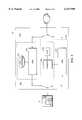
- FIG. 1is a block diagram of an embodiment of a QoS system utilizing the invention
- FIG. 2is a block diagram of an embodiment of the service verification equipment of the invention as shown in FIG. 1;
- FIG. 3is an embodiment of the receiving subsystem of the service verification equipment of the invention.
- FIG. 4is an embodiment of the transmitting subsystem of the service verification equipment of the invention.
- FIG. 5is a flowchart describing the actions of the transmitting subsystem of the service verification equipment of the invention.
- FIG. 6is a flowchart describing the actions of the receiving subsystem of the service verification equipment of the invention.
- FIG. 1An embodiment of the invention providing an in-service virtual circuit QoS test that adds negligible additional traffic to the network and is transparent to the service customer is shown in FIG. 1.
- the WAN 1 showncan be any type of WAN that supports virtual circuits, including for example, but not limited to, ATM or Frame Relay.
- the embodiments of the invention described belowuse the term "cell" meaning a unit aggregation of data routed between an origin and a destination across a network, and at least refers to, but is not limited to, a cell, datagram, frame, or packet associated with any technology that supports virtual circuits.
- Service Verification Equipment (“SVE”) 10, 12is inserted provisionally or permanently at the termination points of the virtual circuit on the service customer premises or at the service provider's point of presence (“POP") between the service customer 5, 15 and the network 1.
- POPpoint of presence
- TMWtest management workstation
- TMW 20communicates with each SVE 10, 12 using management virtual circuits established for this purpose.
- TMW 20communicates with each SVE 10, 12 by an alternate or "out of band” communications link 25, 26.
- TMW 20is used by the service provider to initiate QoS tests. TMW 20 sends a message to each SVE 10, 12 to initiate testing after a delay sufficient to insure that the SVEs 10,12 are prepared for the test. Additional parameters are specified by TMW 20, including any of the QoS parameters to be measured, the content of a test initiation cell, the content of a test termination cell, and the length of the test (which may be specified in units of cells or time). In another embodiment, one of the SVEs 10, 12 initiates testing and specifies the test parameters.
- Testsmay be full or half duplex so that one SVE 10, 12 may test outbound traffic, inbound traffic, or both simultaneously.
- a half duplex testis described. In this embodiment transmitting SVE 10 sends data to receiving SVE 12.
- the roles of SVE 10, 12are reversed.
- each SVE 10, 12simultaneously transmits and receives full duplex data.
- Transmitting SVE 10first inserts a test initiation cell into the virtual circuit under test.
- the test initiation cellWith respect to the virtual circuit identification information in the header, the test initiation cell is indistinguishable from other cells passing across the virtual circuit. The test initiation cell will therefore be transmitted through the network in the same manner as all other cells on the virtual circuit.
- the bytes of payload data contained in the test initiation cellare a Unique Cell Identifier ("UCI").
- UCIUnique Cell Identifier
- the UCIis unique in the sense that for all practical purposes, the probability of the service customer transmitting an identical cell is close to zero.
- the UCIis a random pattern of data such that the probability of a cell of service customer data having the same pattern is equal to approximately 1/2 384 . This probability is determined by the fact that there are 48 bytes in an ATM cell payload, each byte having 8 bits for a total of 384 bits.
- the random patternis examined to determine if it might be a pattern that frequently appears in data, such as, but not limited to, a repeating pattern or all 1's or 0's. In this embodiment, if examination reveals that the pattern might appear frequently in the data, a different pattern is chosen.
- Such examinationcan be manual or automatic and may be done once, if the random pattern is selected once, or each time if a new random pattern is selected for each test.
- the random patternis made known to transmitting SVE 10 and receiving SVE 12 via communication from TMW 20.
- the random patternis made known to transmitting SVE 10 and receiving SVE 12 by a predetermined hardware setting such as DIP switches or storage in ROM.
- Transmitting SVE 10measures and stores QoS data beginning with the first cell transmitted after the transmission of the test initiation cell.
- the datamay include any or all of the cell header, the cell payload, the current time, the elapsed time between each cell, and the number of cells.
- a copy of all cells transmittedare stored.
- transmitting SVE 10computes a checksum for each cell payload, and stores the checksum instead of the cell payload data. This has the advantage of reducing the amount of test data stored and transmitted, and also ensures service customer data privacy.
- all cells transmittedare stored with a time stamp.
- the data required to store the time stampis compressed by calculating the elapsed time from the last cell reception.
- a crc32 payload data checksumis stored along with a elapsed timestamp thereby representing the time and data associated with a 53 byte ATM cell in 6 bytes.
- Transmitting SVE 10terminates the test by inserting a test termination cell into the virtual circuit cell stream.
- this test termination cellis identical to the test initiation cell.
- Receiving SVE 12observes the arriving cells on the virtual circuit under test. It submits each cell to a UCI subsystem that determines if the cell is the test initiation cell containing the UCI. When it observes the test initiation cell, receiving SVE 12 begins measuring and storing QoS data beginning with the first cell received after the initiation cell. Receiving SVE 12 removes the test initiation cell from the data stream, so that the actual data stream of the service customer is not affected by the testing. For each test, receiving SVE 12 stores data parameters for the data it receives that correspond to data parameters transmitting SVE 10 stores for the data it sends.
- receiving SVE 12When receiving SVE 12 receives the test termination cell, the test terminates and receiving SVE 12 removes the test termination cell from the data stream, so that the service customer data stream is not affected by the testing.
- processingoccurs at TMW 20. In another embodiment processing may occur at transmitting SVE 10, receiving SVE 12, TMW 20, or other processing site to which the data collected is forwarded.
- data to evaluate QoS parameterssuch as CMR, CER, SECBR, and CLR are sent to a central collection point so that the cells may be compared on a cell by cell basis.
- testssuch as CDV tests receive confirmation from the transmitting SVE 10 and receiving SVE 12 that the delay between cells did not exceed a QoS value at either end.
- the service customer dataconsists of packets such as those specified by the ATM AAL5 specification that have Cyclic Redundancy Checking ("CRC") or other such error detection mechanisms.
- transmitting SVE 10 and receiving SVE 12may determine whether packet contents were transmitted accurately by calculating the CRC value on the data and comparing the calculated CRC with the received CRC.
- the testruns independently of the service customer and terminates randomly with respect to multiple cells in the service customer data stream, so the first and last AAL5 packets may be incomplete and no CRC calculation can be made for that packet.
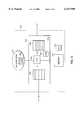
- FIG. 2shows a block diagram of one embodiment of SVE 10.
- SVE 10is described as two interconnected subsystems: receiving subsystem 250 and transmitting subsystem 251.
- the subsystemsshare memory 210 and CPU 215.
- receiving subsystem 250 and transmitting subsystem 251each have its own memory 210.
- receiving subsystem 250 and transmitting subsystem 251each have its own memory 210 and CPU 215.
- cells arriving from WAN 1are received by receiving subsystem 250.
- Cells received from WAN 1first go to Cell Processing Engine ("CPE") 205.
- CPE 205inspects the cell header to determine if the cell is associated with the virtual circuit under test and UCI subsystem 200 checks each cell to determine if it is a test initiation cell. If a cell is not associated with the virtual circuit under test or if a cell does not contain the UCI, CPE 205 passes the cell on to service customer 5. If the cell is associated with the virtual circuit under test and UCI subsystem 200 recognizes a test initiation cell, then a test commences, and CPE 205 does not pass the test initiation cell on to the service customer.
- CPE 205inspects the cell header to determine if the cell is associated with the virtual circuit under test and UCI subsystem 200 checks each cell to determine if it is a test termination cell. If the cell is associated with the virtual circuit under test, then data about the cell, and optionally the cell data itself, is copied into memory 210. The data can then be operated on by CPU 215.
- CPU 215compiles statistics and test results based on data in memory 210. In another embodiment, CPU 215 transmits all collected data to TMW 20. In another embodiment, CPU 215 compiles statistics and test results based on data in memory 210 prior to transmitting the collected statistics and test results to the TMW 20.
- CPE 220Cells going from service customer 5 go through transmitting subsystem 251 and CPE 220. Before a test commences, cells from service customer 5 are passed through CPE 220 to WAN 1. When a test commences, CPE 220 creates a test initiation cell and passes the test initiation cell to WAN 1. CPE 220 then begins collecting QoS data on all cells flowing from service customer 5 to WAN 1. QoS data is stored in memory 210. When a test ends, CPE 220 creates a test termination cell. The test termination cell is passed by CPE 220 to WAN 1. Data collection is then terminated.
- FIG. 3shows a more detailed block diagram of receiving subsystem 250.
- Arriving cellsare queued in Cell Buffer Ram ("CBRAM") 305, which in one embodiment is a FIFO memory of the type well known in the art.
- CBRAMCell Buffer Ram
- Each cellis processed by CPU 310 in FIFO order.
- Filter logic 325 in UCI Subsystem 200compares cell data with the UCI. If the cell is not the UCI, CPU 310 queues the cell on CBRAM 315.
- CAMContent Addressable Memory
- CBRAM 315If the cell is not associated with the virtual circuit under test, then it is queued on CBRAM 315. If the cell is associated with the virtual circuit under test then CPU 310 writes the required data to memory 220 and queues the cell on CBRAM 315. When Filter Logic 325 recognizes a test termination cell, that cell is not passed on, and data logging terminates.
- FIG. 4shows a block diagram of an embodiment of transmitting subsystem 251.
- CBRAM 405Before a test commences, cells transmitted from the service customer are queued in CBRAM 405, and are queued on CBRAM 415 by CPU 410. Cells pass from CBRAM 415 out to WAN 1.
- CPU 410queues a test initiation cell on CBRAM 415. Header data from each cell from the service customer that is queued on CBRAM 405 is then compared to the identifier for the virtual circuit under test using CAM 420. If a cell is not associated with the virtual circuit under test, then it is queued on CBRAM 415. In this way, data is not gathered for customer cells associated with a different virtual circuit.
- the transmitting SVEwaits for an initiate test message from the TMW 505.
- receives the test messageit initializes test variables based on the initiate test message received from the TMW 510.
- the variablesinclude the cell count, the test time to begin and a timeout value for the test.
- Transmitting SVEthen waits the appropriate amount of time for the test to begin 515.
- the transmitting SVEtransmits a test initiation cell 520. Transmitting SVE then waits for the customer to transmit a user cell 525.
- an error messagewill be sent to the TMW 535. If a user cell is transmitted, then the user cell data will be captured and the cell counter will be decremented 540. If the cell counter is not zero 545, then the transmitting SVE waits 525 for the next user cell. The system will loop in this manner until the cell counter has decremented to zero. Once the cell counter decrements to zero, as transmitting SVE will transmit a test termination cell and transmit the test results to the TMW 500.
- FIG. 6is a flowchart describing the actions of the receiving subsystem of the service verification equipment of the invention.
- the receiving SVEwaits until it has received the initiate test message from the TMW 605. Once it receives the test message receiving SVE sets test variables based on the information in the initiate test message and sets a timeout value for the test 610. Receiving SVE then waits for the test initiation cell 615. The receiving SVE waits until the test initiation cell is captured or until a timeout occurs 620. Once the test initiation cell has been received, then the receiving SVE waits for a user cell to be received 625. If no user cell is received before timeout 630, then an error message will be sent to the TMW 635.
- the appropriate user cell datawill be collected 640. If the cell is determined not to be the test termination cell, then receiving SVE waits for the next cell 625. If a test termination cell is received 645, the receiving SVE will transmit the test results to the TMW 650.
Landscapes
- Engineering & Computer Science (AREA)
- Computer Networks & Wireless Communication (AREA)
- Signal Processing (AREA)
- Data Exchanges In Wide-Area Networks (AREA)
Abstract
Description
Claims (19)
Priority Applications (6)
| Application Number | Priority Date | Filing Date | Title |
|---|---|---|---|
| US08/992,755US6147998A (en) | 1997-08-26 | 1997-12-17 | Method and apparatus for performing in-service quality of service testing |
| GB0004009AGB2344255A (en) | 1997-08-26 | 1998-08-24 | Method and apparatus for performing in-service quality of service testing |
| PCT/US1998/017496WO1999011094A1 (en) | 1997-08-26 | 1998-08-24 | Method and apparatus for performing in-service quality of service testing |
| CA002301896ACA2301896A1 (en) | 1997-08-26 | 1998-08-24 | Method and apparatus for performing in-service quality of service testing |
| AU91165/98AAU9116598A (en) | 1997-08-26 | 1998-08-24 | Method and apparatus for performing in-service quality of service testing |
| DE19882639TDE19882639T1 (en) | 1997-08-26 | 1998-08-24 | Method and apparatus for performing an in-service quality test |
Applications Claiming Priority (2)
| Application Number | Priority Date | Filing Date | Title |
|---|---|---|---|
| US5695597P | 1997-08-26 | 1997-08-26 | |
| US08/992,755US6147998A (en) | 1997-08-26 | 1997-12-17 | Method and apparatus for performing in-service quality of service testing |
Publications (1)
| Publication Number | Publication Date |
|---|---|
| US6147998Atrue US6147998A (en) | 2000-11-14 |
Family
ID=26735892
Family Applications (1)
| Application Number | Title | Priority Date | Filing Date |
|---|---|---|---|
| US08/992,755Expired - LifetimeUS6147998A (en) | 1997-08-26 | 1997-12-17 | Method and apparatus for performing in-service quality of service testing |
Country Status (6)
| Country | Link |
|---|---|
| US (1) | US6147998A (en) |
| AU (1) | AU9116598A (en) |
| CA (1) | CA2301896A1 (en) |
| DE (1) | DE19882639T1 (en) |
| GB (1) | GB2344255A (en) |
| WO (1) | WO1999011094A1 (en) |
Cited By (30)
| Publication number | Priority date | Publication date | Assignee | Title |
|---|---|---|---|---|
| WO2001039419A3 (en)* | 1999-11-29 | 2002-02-14 | Verizon Lab Inc | System and method for monitoring the performance and quality of service provided by a communication service or network |
| US20030053419A1 (en)* | 2001-08-22 | 2003-03-20 | Toshiyuki Kanazawa | Packet communication quality measurement method and system |
| US20030233603A1 (en)* | 2002-03-28 | 2003-12-18 | Hitachi, Ltd. | Method for detecting fault between storage devices, and storage device used for the same |
| US20030236844A1 (en)* | 2002-06-25 | 2003-12-25 | Kaler Christopher G. | Testing distributed applications |
| US6690649B1 (en)* | 1998-05-22 | 2004-02-10 | Nec Corporation | QoS management apparatus |
| US20040034492A1 (en)* | 2001-03-30 | 2004-02-19 | Conway Adrian E. | Passive system and method for measuring and monitoring the quality of service in a communications network |
| US20040058652A1 (en)* | 2002-03-21 | 2004-03-25 | Mcgregor Christopher M. | Method and system for quality of service (QoS) monitoring for wireless devices |
| US6763024B1 (en)* | 1999-10-14 | 2004-07-13 | Alcatel Canada Inc. | Method and devices for cell loss detection in ATM telecommunication devices |
| US20040141464A1 (en)* | 2003-01-21 | 2004-07-22 | Bellsouth Intellectual Property Corporation | Method and system for obtaining logical performance data for a circuit in a data network |
| US20040143653A1 (en)* | 2003-01-21 | 2004-07-22 | Bellsouth Intellectual Property Corporation | Method and system for provisioning and maintaining a circuit in a data network |
| US6895440B1 (en)* | 2000-05-25 | 2005-05-17 | Cisco Technology, Inc. | Network component performance testing |
| US6907003B1 (en)* | 1998-12-23 | 2005-06-14 | Nortel Networks Limited | Method of monitoring packet communications traffic |
| US20050135263A1 (en)* | 2003-12-23 | 2005-06-23 | Bellsouth Intellectual Property Corporation | Method and system for real time simultaneous monitoring of logical circuits in a data network |
| US20050172160A1 (en)* | 2003-12-23 | 2005-08-04 | Bellsouth Intellectual Property Corporation | Method and system for automatically rerouting logical circuit data in a virtual private network |
| US6961315B1 (en)* | 2000-11-21 | 2005-11-01 | At&T Corp. | Technique for monitoring conversational voice over packet |
| EP1689121A1 (en) | 2005-02-04 | 2006-08-09 | Visual Networks Operations, Inc. | Methods and apparatus for identifying chronic performance problems on data networks |
| US7106698B1 (en)* | 1998-09-16 | 2006-09-12 | Cisco Technology, Inc. | System for triggering the control plane in an asynchronous connection-oriented transmission network |
| CN100382517C (en)* | 2005-04-04 | 2008-04-16 | 杭州华三通信技术有限公司 | Network service quality testing method and system |
| CN100463418C (en)* | 2005-11-23 | 2009-02-18 | 杭州华三通信技术有限公司 | Network performance testing method, system and network equipment |
| US7609623B2 (en) | 2003-12-23 | 2009-10-27 | At&T Intellectual Property I, L.P. | Method and system for automatically rerouting data from an overbalanced logical circuit in a data network |
| US7630302B2 (en) | 2003-12-23 | 2009-12-08 | At&T Intellectual Property I, L.P. | Method and system for providing a failover circuit for rerouting logical circuit data in a data network |
| US7646707B2 (en) | 2003-12-23 | 2010-01-12 | At&T Intellectual Property I, L.P. | Method and system for automatically renaming logical circuit identifiers for rerouted logical circuits in a data network |
| US7768904B2 (en) | 2004-04-22 | 2010-08-03 | At&T Intellectual Property I, L.P. | Method and system for fail-safe renaming of logical circuit identifiers for rerouted logical circuits in a data network |
| US8199638B2 (en) | 2003-12-23 | 2012-06-12 | At&T Intellectual Property I, L.P. | Method and system for automatically rerouting logical circuit data in a data network |
| US8203933B2 (en) | 2003-12-23 | 2012-06-19 | At&T Intellectual Property I, L.P. | Method and system for automatically identifying a logical circuit failure in a data network |
| US8223632B2 (en) | 2003-12-23 | 2012-07-17 | At&T Intellectual Property I, L.P. | Method and system for prioritized rerouting of logical circuit data in a data network |
| US8295162B2 (en) | 2006-05-16 | 2012-10-23 | At&T Intellectual Property I, L.P. | System and method to achieve sub-second routing performance |
| US8339938B2 (en) | 2004-04-22 | 2012-12-25 | At&T Intellectual Property I, L.P. | Method and system for automatically tracking the rerouting of logical circuit data in a data network |
| US8339988B2 (en) | 2004-04-22 | 2012-12-25 | At&T Intellectual Property I, L.P. | Method and system for provisioning logical circuits for intermittent use in a data network |
| US8345537B2 (en) | 2004-04-22 | 2013-01-01 | At&T Intellectual Property I, L.P. | Methods and systems for automatically rerouting logical circuit data from a logical circuit failure to a dedicated backup circuit in a data network |
Families Citing this family (1)
| Publication number | Priority date | Publication date | Assignee | Title |
|---|---|---|---|---|
| FI20001578A7 (en) | 2000-06-30 | 2001-12-31 | Nokia Corp | QoS architecture |
Citations (24)
| Publication number | Priority date | Publication date | Assignee | Title |
|---|---|---|---|---|
| US4296495A (en)* | 1978-10-31 | 1981-10-20 | Thomson Csf | Device for measuring the quality of a digital radio link |
| US4406919A (en)* | 1980-07-22 | 1983-09-27 | Siemens Aktiengesellschaft | Method and apparatus for monitoring intermediate regenerative repeaters |
| US4713810A (en)* | 1985-09-19 | 1987-12-15 | Gte Sprint Communications Corp. | Diagnostic technique for determining fault locations within a digital transmission system |
| US4737949A (en)* | 1985-10-22 | 1988-04-12 | Kokusai Denshin Denwa Co., Ltd. | Transmission system for digital repeater supervisory code transmission |
| US4742518A (en)* | 1986-05-27 | 1988-05-03 | American Telephone And Telegraph Company, At&T Bell Laboratories | Fault location system for a digital transmission line |
| US4750175A (en)* | 1986-08-29 | 1988-06-07 | Pactel Communications Companies | Network diagnostic apparatus and method |
| JPH03186022A (en)* | 1989-12-15 | 1991-08-14 | Mitsubishi Electric Corp | Fault detection device |
| US5163057A (en)* | 1989-04-18 | 1992-11-10 | Wandel & Goltermann Gmbh & Co. | Method of and circuit arrangement for determining a cell loss and/or a cell insertion during traversal of a cell oriented transmission device by cell structured signals |
| EP0528075A1 (en)* | 1991-08-19 | 1993-02-24 | ALCATEL BELL Naamloze Vennootschap | Performance measurement device for a telecommunication path and method used therein |
| US5191583A (en)* | 1989-11-03 | 1993-03-02 | Microcom Systems, Inc. | Method and apparatus for effecting efficient transmission of data |
| US5369634A (en)* | 1990-05-15 | 1994-11-29 | Alcatel N.V. | Transmission quality assessment arrangement |
| US5373504A (en)* | 1992-04-09 | 1994-12-13 | Fujitsu Limited | Apparatus and a method for setting a communication path |
| US5450394A (en)* | 1994-03-10 | 1995-09-12 | Northern Telecom Limited | Delay monitoring of telecommunication networks |
| US5450440A (en)* | 1991-10-23 | 1995-09-12 | Nec Corporation | Monitor system for digital communication apparatus |
| US5515363A (en)* | 1994-06-30 | 1996-05-07 | Digital Equipment Corporation | Traffic shaping system with transmit latency feedback for asynchronous transfer mode networks |
| US5519689A (en)* | 1993-06-12 | 1996-05-21 | Samsung Electronics Co., Ltd. | Traffic control apparatus and method of user-network interface of asynchronous transfer mode |
| US5521907A (en)* | 1995-04-25 | 1996-05-28 | Visual Networks, Inc. | Method and apparatus for non-intrusive measurement of round trip delay in communications networks |
| US5524006A (en)* | 1995-02-15 | 1996-06-04 | Motorola, Inc. | Second-order leaky bucket device and method for traffic management in cell relay networks |
| US5533009A (en)* | 1995-02-03 | 1996-07-02 | Bell Communications Research, Inc. | Bandwidth management and access control for an ATM network |
| US5563874A (en)* | 1995-01-27 | 1996-10-08 | Bell Communications Research, Inc. | Error monitoring algorithm for broadband signaling |
| US5590116A (en)* | 1995-02-09 | 1996-12-31 | Wandel & Goltermann Technologies, Inc. | Multiport analyzing, time stamp synchronizing and parallel communicating |
| US5640401A (en)* | 1989-06-01 | 1997-06-17 | Mitsubishi Denki Kabushiki Kaisha | Communication circuit fault detector |
| US5737338A (en)* | 1993-07-19 | 1998-04-07 | Fujitsu Limited | ATM exchange and method of testing same |
| US5764626A (en)* | 1995-11-17 | 1998-06-09 | Telecommunications Techniques Corporation | Rate-matched cell identification and modification, replacement, or insertion for test and measurement of ATM network virtual connections |
- 1997
- 1997-12-17USUS08/992,755patent/US6147998A/ennot_activeExpired - Lifetime
- 1998
- 1998-08-24AUAU91165/98Apatent/AU9116598A/ennot_activeAbandoned
- 1998-08-24DEDE19882639Tpatent/DE19882639T1/ennot_activeWithdrawn
- 1998-08-24GBGB0004009Apatent/GB2344255A/ennot_activeWithdrawn
- 1998-08-24CACA002301896Apatent/CA2301896A1/ennot_activeAbandoned
- 1998-08-24WOPCT/US1998/017496patent/WO1999011094A1/enactiveApplication Filing
Patent Citations (25)
| Publication number | Priority date | Publication date | Assignee | Title |
|---|---|---|---|---|
| US4296495A (en)* | 1978-10-31 | 1981-10-20 | Thomson Csf | Device for measuring the quality of a digital radio link |
| US4406919A (en)* | 1980-07-22 | 1983-09-27 | Siemens Aktiengesellschaft | Method and apparatus for monitoring intermediate regenerative repeaters |
| US4713810A (en)* | 1985-09-19 | 1987-12-15 | Gte Sprint Communications Corp. | Diagnostic technique for determining fault locations within a digital transmission system |
| US4737949A (en)* | 1985-10-22 | 1988-04-12 | Kokusai Denshin Denwa Co., Ltd. | Transmission system for digital repeater supervisory code transmission |
| US4742518A (en)* | 1986-05-27 | 1988-05-03 | American Telephone And Telegraph Company, At&T Bell Laboratories | Fault location system for a digital transmission line |
| US4750175A (en)* | 1986-08-29 | 1988-06-07 | Pactel Communications Companies | Network diagnostic apparatus and method |
| US5163057A (en)* | 1989-04-18 | 1992-11-10 | Wandel & Goltermann Gmbh & Co. | Method of and circuit arrangement for determining a cell loss and/or a cell insertion during traversal of a cell oriented transmission device by cell structured signals |
| US5640401A (en)* | 1989-06-01 | 1997-06-17 | Mitsubishi Denki Kabushiki Kaisha | Communication circuit fault detector |
| US5191583A (en)* | 1989-11-03 | 1993-03-02 | Microcom Systems, Inc. | Method and apparatus for effecting efficient transmission of data |
| JPH03186022A (en)* | 1989-12-15 | 1991-08-14 | Mitsubishi Electric Corp | Fault detection device |
| US5369634A (en)* | 1990-05-15 | 1994-11-29 | Alcatel N.V. | Transmission quality assessment arrangement |
| US5343463A (en)* | 1991-08-19 | 1994-08-30 | Alcatel N.V. | Performance measurement system for a telecommunication path and device used therein |
| EP0528075A1 (en)* | 1991-08-19 | 1993-02-24 | ALCATEL BELL Naamloze Vennootschap | Performance measurement device for a telecommunication path and method used therein |
| US5450440A (en)* | 1991-10-23 | 1995-09-12 | Nec Corporation | Monitor system for digital communication apparatus |
| US5373504A (en)* | 1992-04-09 | 1994-12-13 | Fujitsu Limited | Apparatus and a method for setting a communication path |
| US5519689A (en)* | 1993-06-12 | 1996-05-21 | Samsung Electronics Co., Ltd. | Traffic control apparatus and method of user-network interface of asynchronous transfer mode |
| US5737338A (en)* | 1993-07-19 | 1998-04-07 | Fujitsu Limited | ATM exchange and method of testing same |
| US5450394A (en)* | 1994-03-10 | 1995-09-12 | Northern Telecom Limited | Delay monitoring of telecommunication networks |
| US5515363A (en)* | 1994-06-30 | 1996-05-07 | Digital Equipment Corporation | Traffic shaping system with transmit latency feedback for asynchronous transfer mode networks |
| US5563874A (en)* | 1995-01-27 | 1996-10-08 | Bell Communications Research, Inc. | Error monitoring algorithm for broadband signaling |
| US5533009A (en)* | 1995-02-03 | 1996-07-02 | Bell Communications Research, Inc. | Bandwidth management and access control for an ATM network |
| US5590116A (en)* | 1995-02-09 | 1996-12-31 | Wandel & Goltermann Technologies, Inc. | Multiport analyzing, time stamp synchronizing and parallel communicating |
| US5524006A (en)* | 1995-02-15 | 1996-06-04 | Motorola, Inc. | Second-order leaky bucket device and method for traffic management in cell relay networks |
| US5521907A (en)* | 1995-04-25 | 1996-05-28 | Visual Networks, Inc. | Method and apparatus for non-intrusive measurement of round trip delay in communications networks |
| US5764626A (en)* | 1995-11-17 | 1998-06-09 | Telecommunications Techniques Corporation | Rate-matched cell identification and modification, replacement, or insertion for test and measurement of ATM network virtual connections |
Non-Patent Citations (7)
| Title |
|---|
| Farkouh, S. "Managing ATM-Based Broadband Networks," IEEE Communications Magazine, vol. 31, No. 5, May 1, 1993, pp. 82-86. |
| Farkouh, S. Managing ATM Based Broadband Networks, IEEE Communications Magazine , vol. 31, No. 5, May 1, 1993, pp. 82 86.* |
| Jung J I et al. QOS Management and Performance Monitoring in ATM Networks, Proceedings of the Global Communications Conference ( GLOBECOM ), Houston, Nov. 29 Dec. 2, 1993, vol. 2, Nov. 29, 1993, pp. 708 712.* |
| Jung J-I et al. "QOS Management and Performance Monitoring in ATM Networks," Proceedings of the Global Communications Conference (GLOBECOM), Houston, Nov. 29-Dec. 2, 1993, vol. 2, Nov. 29, 1993, pp. 708-712. |
| Kim S. "An Information Model for Performance Monitoring of Broadband Network Termination System," Proceedings of the Region 10 Annual International Conference (Tenco, Singapore), Aug. 22-26, 1994, vol. 1, No. Conf. 9, Aug. 22, 1994, pp. 451-455. |
| Kim S. An Information Model for Performance Monitoring of Broadband Network Termination System, Proceedings of the Region 10 Annual International Conference (Tenco, Singapore), Aug. 22 26, 1994, vol. 1, No. Conf. 9, Aug. 22, 1994, pp. 451 455.* |
| Patent Cooperation Treaty, International Search Report, International Application No. PCT/US 98/17496, mailed on Jan. 27, 1999, 4 pages.* |
Cited By (66)
| Publication number | Priority date | Publication date | Assignee | Title |
|---|---|---|---|---|
| US6690649B1 (en)* | 1998-05-22 | 2004-02-10 | Nec Corporation | QoS management apparatus |
| US20060256795A1 (en)* | 1998-09-16 | 2006-11-16 | Claude Basso | System for triggering the control plane in an asynchronous connection-oriented transmission network |
| US7106698B1 (en)* | 1998-09-16 | 2006-09-12 | Cisco Technology, Inc. | System for triggering the control plane in an asynchronous connection-oriented transmission network |
| US6907003B1 (en)* | 1998-12-23 | 2005-06-14 | Nortel Networks Limited | Method of monitoring packet communications traffic |
| US6763024B1 (en)* | 1999-10-14 | 2004-07-13 | Alcatel Canada Inc. | Method and devices for cell loss detection in ATM telecommunication devices |
| WO2001039419A3 (en)* | 1999-11-29 | 2002-02-14 | Verizon Lab Inc | System and method for monitoring the performance and quality of service provided by a communication service or network |
| US6895440B1 (en)* | 2000-05-25 | 2005-05-17 | Cisco Technology, Inc. | Network component performance testing |
| US6961315B1 (en)* | 2000-11-21 | 2005-11-01 | At&T Corp. | Technique for monitoring conversational voice over packet |
| US7376132B2 (en)* | 2001-03-30 | 2008-05-20 | Verizon Laboratories Inc. | Passive system and method for measuring and monitoring the quality of service in a communications network |
| US20040034492A1 (en)* | 2001-03-30 | 2004-02-19 | Conway Adrian E. | Passive system and method for measuring and monitoring the quality of service in a communications network |
| US20030053419A1 (en)* | 2001-08-22 | 2003-03-20 | Toshiyuki Kanazawa | Packet communication quality measurement method and system |
| US7496046B2 (en)* | 2001-08-22 | 2009-02-24 | Nippon Telegraph And Telephone Corporation | Packet communication quality measurement method and system |
| US20040058652A1 (en)* | 2002-03-21 | 2004-03-25 | Mcgregor Christopher M. | Method and system for quality of service (QoS) monitoring for wireless devices |
| US7596373B2 (en) | 2002-03-21 | 2009-09-29 | Mcgregor Christopher M | Method and system for quality of service (QoS) monitoring for wireless devices |
| US7155636B2 (en) | 2002-03-28 | 2006-12-26 | Hitachi, Ltd. | Method for detecting faults between storage devices and storage devices using the same |
| US20030233603A1 (en)* | 2002-03-28 | 2003-12-18 | Hitachi, Ltd. | Method for detecting fault between storage devices, and storage device used for the same |
| US7092995B2 (en)* | 2002-06-25 | 2006-08-15 | Microsoft Corporation | Testing distributed applications |
| US20030236844A1 (en)* | 2002-06-25 | 2003-12-25 | Kaler Christopher G. | Testing distributed applications |
| US7890618B2 (en) | 2003-01-21 | 2011-02-15 | At&T Intellectual Property I, L.P. | Method and system for provisioning and maintaining a circuit in a data network |
| US8200802B2 (en) | 2003-01-21 | 2012-06-12 | At&T Intellectual Property I, L.P. | Methods and systems for provisioning and maintaining a circuit in a data network |
| US20040143653A1 (en)* | 2003-01-21 | 2004-07-22 | Bellsouth Intellectual Property Corporation | Method and system for provisioning and maintaining a circuit in a data network |
| US20040141464A1 (en)* | 2003-01-21 | 2004-07-22 | Bellsouth Intellectual Property Corporation | Method and system for obtaining logical performance data for a circuit in a data network |
| US7391734B2 (en)* | 2003-01-21 | 2008-06-24 | At&T Delaware Intellectual Property Corporation, Inc. | Method and system for obtaining logical performance data for a circuit in a data network |
| US7469282B2 (en)* | 2003-01-21 | 2008-12-23 | At&T Intellectual Property I, L.P. | Method and system for provisioning and maintaining a circuit in a data network |
| US20090103544A1 (en)* | 2003-01-21 | 2009-04-23 | At&T Intellectual Property I, L.P. | Method and system for provisioning and maintaining a circuit in a data network |
| US7646707B2 (en) | 2003-12-23 | 2010-01-12 | At&T Intellectual Property I, L.P. | Method and system for automatically renaming logical circuit identifiers for rerouted logical circuits in a data network |
| US8031588B2 (en) | 2003-12-23 | 2011-10-04 | At&T Intellectual Property I, L.P. | Methods and systems for automatically renaming logical Circuit identifiers for rerouted logical circuits in a data network |
| US9059900B2 (en) | 2003-12-23 | 2015-06-16 | At&T Intellectual Property I, L.P. | Methods and systems for automatically rerouting logical circuit data |
| US7609623B2 (en) | 2003-12-23 | 2009-10-27 | At&T Intellectual Property I, L.P. | Method and system for automatically rerouting data from an overbalanced logical circuit in a data network |
| US7630302B2 (en) | 2003-12-23 | 2009-12-08 | At&T Intellectual Property I, L.P. | Method and system for providing a failover circuit for rerouting logical circuit data in a data network |
| US7639606B2 (en) | 2003-12-23 | 2009-12-29 | At&T Intellectual Property I, L.P. | Method and system for automatically rerouting logical circuit data in a virtual private network |
| US7639623B2 (en) | 2003-12-23 | 2009-12-29 | At&T Intellectual Property I, L.P. | Method and system for real time simultaneous monitoring of logical circuits in a data network |
| US8942086B2 (en) | 2003-12-23 | 2015-01-27 | At&T Intellectual Property I, L.P. | Methods and systems for automatically rerouting logical circuit data in a data network |
| US8937856B2 (en) | 2003-12-23 | 2015-01-20 | At&T Intellectual Property I, L.P. | Methods and systems to reroute data in a data network |
| US20050172160A1 (en)* | 2003-12-23 | 2005-08-04 | Bellsouth Intellectual Property Corporation | Method and system for automatically rerouting logical circuit data in a virtual private network |
| US8031620B2 (en) | 2003-12-23 | 2011-10-04 | At&T Intellectual Property I, L.P. | Method and system for real time simultaneous monitoring of logical circuits in a data network |
| US8547830B2 (en) | 2003-12-23 | 2013-10-01 | At&T Intellectual Property I, L.P. | Methods and systems to reroute data in a data network |
| US20050135263A1 (en)* | 2003-12-23 | 2005-06-23 | Bellsouth Intellectual Property Corporation | Method and system for real time simultaneous monitoring of logical circuits in a data network |
| US8199638B2 (en) | 2003-12-23 | 2012-06-12 | At&T Intellectual Property I, L.P. | Method and system for automatically rerouting logical circuit data in a data network |
| US8203933B2 (en) | 2003-12-23 | 2012-06-19 | At&T Intellectual Property I, L.P. | Method and system for automatically identifying a logical circuit failure in a data network |
| US8223632B2 (en) | 2003-12-23 | 2012-07-17 | At&T Intellectual Property I, L.P. | Method and system for prioritized rerouting of logical circuit data in a data network |
| US8243592B2 (en) | 2003-12-23 | 2012-08-14 | At&T Intellectual Property I, L.P. | Methods and systems for automatically rerouting data in a data network |
| US8750102B2 (en) | 2003-12-23 | 2014-06-10 | At&T Intellectual Property I, L.P. | Methods and systems for automatically rerouting logical circuit data in a data network |
| US8730795B2 (en) | 2003-12-23 | 2014-05-20 | At&T Intellectual Property I, L.P. | Methods and systems for automatically rerouting logical circuit data |
| US8711679B2 (en) | 2003-12-23 | 2014-04-29 | At&T Intellectual Property I, L.P. | Methods and systems for automatically identifying a logical circuit failure in a data network |
| US8345543B2 (en) | 2003-12-23 | 2013-01-01 | At&T Intellectual Property I, L.P. | Methods and systems for automatically rerouting logical circuit data |
| US8547831B2 (en) | 2003-12-23 | 2013-10-01 | At&T Intellectual Property I, L.P. | Methods and systems for automatically rerouting logical circuit data |
| US8345537B2 (en) | 2004-04-22 | 2013-01-01 | At&T Intellectual Property I, L.P. | Methods and systems for automatically rerouting logical circuit data from a logical circuit failure to a dedicated backup circuit in a data network |
| US8737196B2 (en) | 2004-04-22 | 2014-05-27 | At&T Intellectual Property I, L.P. | Methods and systems for automatically tracking the rerouting of logical circuit data in a data network |
| US8509118B2 (en) | 2004-04-22 | 2013-08-13 | At&T Intellectual Property I, L.P. | Methods and systems for provisioning logical circuits for intermittent use in a data network |
| US9338051B2 (en) | 2004-04-22 | 2016-05-10 | At&T Intellectual Property I, L.P. | Methods and systems for automatically tracking the rerouting of logical circuit data in a data network |
| US8565074B2 (en) | 2004-04-22 | 2013-10-22 | At&T Intellectual Property I, L.P. | Methods and systems for automatically tracking the rerouting of logical circuit data in a data network |
| US8665705B2 (en) | 2004-04-22 | 2014-03-04 | At&T Intellectual Property I, L.P. | Methods and systems for automatically rerouting logical circuit data from a logical circuit failure to a dedicated backup circuit in a data network |
| US8670348B2 (en) | 2004-04-22 | 2014-03-11 | At&T Intellectual Property I, L.P. | Methods and systems for provisioning logical circuits for intermittent use in a data network |
| US8339988B2 (en) | 2004-04-22 | 2012-12-25 | At&T Intellectual Property I, L.P. | Method and system for provisioning logical circuits for intermittent use in a data network |
| US8339938B2 (en) | 2004-04-22 | 2012-12-25 | At&T Intellectual Property I, L.P. | Method and system for automatically tracking the rerouting of logical circuit data in a data network |
| US8509058B2 (en) | 2004-04-22 | 2013-08-13 | At&T Intellectual Property I, L.P. | Methods and systems for automatically rerouting logical circuit data from a logical circuit failure to a dedicated backup circuit in a data network |
| US9148365B2 (en) | 2004-04-22 | 2015-09-29 | At&T Intellectual Property I, L.P. | Methods and systems for automatically tracking the rerouting of logical circuit data in a data network |
| US8953435B2 (en) | 2004-04-22 | 2015-02-10 | At&T Intellectual Property I, L.P. | Methods and systems for automatically tracking the rerouting of logical circuit data in a data network |
| US7768904B2 (en) | 2004-04-22 | 2010-08-03 | At&T Intellectual Property I, L.P. | Method and system for fail-safe renaming of logical circuit identifiers for rerouted logical circuits in a data network |
| US8953495B2 (en) | 2004-04-22 | 2015-02-10 | At&T Intellectual Property I, L.P. | Methods and systems for provisioning logical circuits for intermittent use in a data network |
| EP1689121A1 (en) | 2005-02-04 | 2006-08-09 | Visual Networks Operations, Inc. | Methods and apparatus for identifying chronic performance problems on data networks |
| CN100382517C (en)* | 2005-04-04 | 2008-04-16 | 杭州华三通信技术有限公司 | Network service quality testing method and system |
| CN100463418C (en)* | 2005-11-23 | 2009-02-18 | 杭州华三通信技术有限公司 | Network performance testing method, system and network equipment |
| US8873379B2 (en) | 2006-05-16 | 2014-10-28 | At&T Intellectual Property I, L.P. | System and method to achieve sub-second routing performance |
| US8295162B2 (en) | 2006-05-16 | 2012-10-23 | At&T Intellectual Property I, L.P. | System and method to achieve sub-second routing performance |
Also Published As
| Publication number | Publication date |
|---|---|
| WO1999011094A1 (en) | 1999-03-04 |
| GB2344255A8 (en) | 2000-06-28 |
| CA2301896A1 (en) | 1999-03-04 |
| GB0004009D0 (en) | 2000-04-12 |
| AU9116598A (en) | 1999-03-16 |
| DE19882639T1 (en) | 2000-08-10 |
| GB2344255A (en) | 2000-05-31 |
Similar Documents
| Publication | Publication Date | Title |
|---|---|---|
| US6147998A (en) | Method and apparatus for performing in-service quality of service testing | |
| US5793976A (en) | Method and apparatus for performance monitoring in electronic communications networks | |
| EP1646183B1 (en) | Method and apparatus for non-intrusive measurement of delay variation of data traffic on communication networks | |
| US6865150B1 (en) | System and method for controlling admission of voice communications in a packet network | |
| US5764626A (en) | Rate-matched cell identification and modification, replacement, or insertion for test and measurement of ATM network virtual connections | |
| US5898674A (en) | System and method for performing non-disruptive diagnostics through a frame relay circuit | |
| US6038231A (en) | Data suppression and regeneration | |
| US7126911B2 (en) | Timer rollover handling mechanism for traffic policing | |
| US6253207B1 (en) | Method and apparatus for transporting multimedia information over heterogeneous wide area networks | |
| US20020016937A1 (en) | Method and apparatus for utilizing a network processor as part of a test system | |
| US20020015387A1 (en) | Voice traffic packet capture and analysis tool for a data network | |
| US6269082B1 (en) | System and method for multiplexing a frame relay virtual circuit and for performing non-disruptive diagnostics through a circuit using asynchronous transfer mode | |
| US20020091495A1 (en) | Monitoring traffic in telecommunications networks | |
| US20020016708A1 (en) | Method and apparatus for utilizing a network processor as part of a test system | |
| KR100486666B1 (en) | Methods of Performance Estimation in Provisioning Delay Intolerant Data Services | |
| US6888849B2 (en) | Method for evaluating capacity utilization of a terminus in a communication system | |
| US6631119B1 (en) | System and method for measuring the efficiency of data delivery in a communication network | |
| CA2237986C (en) | Instrument for test and measurement of atm network virtual connections | |
| EP0979566B1 (en) | Data suppression and regeneration | |
| De Prycker et al. | An ATM switching architecture with intrinsic multicast capabilities for the Belgian broadband experiment | |
| US6665302B2 (en) | Method and system for handling a loop back connection using a priority unspecified bit rate in ADSL interface | |
| US20040057388A1 (en) | Method and device for monitoring a data transmission | |
| US6982981B1 (en) | Method for configuring a network termination unit | |
| KR970002719B1 (en) | Variable bandwidth allocation device and method of time slot method to connect lans | |
| KR100323762B1 (en) | Device for segmentation and reassembly of asynchronous transfer mode and method for segmentation and reassembly |
Legal Events
| Date | Code | Title | Description |
|---|---|---|---|
| AS | Assignment | Owner name:NET2NET CORPORATION, MASSACHUSETTS Free format text:ASSIGNMENT OF ASSIGNORS INTEREST;ASSIGNORS:KELLEY, PAUL W.;MACEACHERN, STUART P.;BECK, RALPH L.;REEL/FRAME:008912/0985 Effective date:19971216 | |
| STCF | Information on status: patent grant | Free format text:PATENTED CASE | |
| FEPP | Fee payment procedure | Free format text:PAYOR NUMBER ASSIGNED (ORIGINAL EVENT CODE: ASPN); ENTITY STATUS OF PATENT OWNER: SMALL ENTITY | |
| AS | Assignment | Owner name:SILICON VALLEY BANK, MASSACHUSETTS Free format text:SECURITY AGREEMENT;ASSIGNORS:VISUAL NETWORKS, INC.;VISUAL NETWORKS OPERATIONS, INC.;VISUAL NETWORKS INVESTMENTS, INC.;AND OTHERS;REEL/FRAME:011641/0979 Effective date:20010228 | |
| AS | Assignment | Owner name:VISUAL NETWORKS OPERATIONS, INC., MARYLAND Free format text:ASSIGNMENT OF ASSIGNORS INTEREST;ASSIGNOR:VISUAL NETWORKS TECHNOLOGIES, INC.;REEL/FRAME:015008/0554 Effective date:20040225 Owner name:VISUAL NETWORKS TECHNOLOGIES, INC., CALIFORNIA Free format text:ASSIGNMENT OF ASSIGNORS INTEREST;ASSIGNOR:VISUAL NETWORKS, INC.;REEL/FRAME:015044/0357 Effective date:20040225 | |
| FPAY | Fee payment | Year of fee payment:4 | |
| CC | Certificate of correction | ||
| AS | Assignment | Owner name:SPECIAL SITUATIONS FUND III, L.P., NEW YORK Free format text:SECURITY AGREEMENT;ASSIGNORS:VISUAL NETWORKS, INC.;VISUAL NETWORKS OPERATIONS, INC.;VISUAL NETWORKS INTERNATIONAL OPERATIONS, INC.;AND OTHERS;REEL/FRAME:016489/0725 Effective date:20050808 Owner name:SPECIAL SITUATIONS CAYMAN FUND, L.P., CAYMAN ISLAN Free format text:SECURITY AGREEMENT;ASSIGNORS:VISUAL NETWORKS, INC.;VISUAL NETWORKS OPERATIONS, INC.;VISUAL NETWORKS INTERNATIONAL OPERATIONS, INC.;AND OTHERS;REEL/FRAME:016489/0725 Effective date:20050808 Owner name:SPECIAL SITUATIONS PRIVATE EQUITY FUND, L.P., NEW Free format text:SECURITY AGREEMENT;ASSIGNORS:VISUAL NETWORKS, INC.;VISUAL NETWORKS OPERATIONS, INC.;VISUAL NETWORKS INTERNATIONAL OPERATIONS, INC.;AND OTHERS;REEL/FRAME:016489/0725 Effective date:20050808 Owner name:SPECIAL SITUATIONS TECHNOLOGY FUND, L.P., NEW YORK Free format text:SECURITY AGREEMENT;ASSIGNORS:VISUAL NETWORKS, INC.;VISUAL NETWORKS OPERATIONS, INC.;VISUAL NETWORKS INTERNATIONAL OPERATIONS, INC.;AND OTHERS;REEL/FRAME:016489/0725 Effective date:20050808 Owner name:SPECIAL SITUATIONS TECHNOLOGY FUND II, L.P., NEW Y Free format text:SECURITY AGREEMENT;ASSIGNORS:VISUAL NETWORKS, INC.;VISUAL NETWORKS OPERATIONS, INC.;VISUAL NETWORKS INTERNATIONAL OPERATIONS, INC.;AND OTHERS;REEL/FRAME:016489/0725 Effective date:20050808 | |
| FPAY | Fee payment | Year of fee payment:8 | |
| FPAY | Fee payment | Year of fee payment:12 | |
| AS | Assignment | Owner name:VISUAL NETWORKS OPERATIONS, INC., MARYLAND Free format text:RELEASE BY SECURED PARTY;ASSIGNORS:SPECIAL SITUATIONS FUND III, L.P.;SPECIAL SITUATIONS CAYMAN FUND, L.P.;SPECIAL SITUATIONS PRIVATE EQUITY FUND, L.P.;AND OTHERS;REEL/FRAME:035448/0316 Effective date:20150211 Owner name:VISUAL NETWORKS TECHNOLOGIES, INC., CALIFORNIA Free format text:RELEASE BY SECURED PARTY;ASSIGNORS:SPECIAL SITUATIONS FUND III, L.P.;SPECIAL SITUATIONS CAYMAN FUND, L.P.;SPECIAL SITUATIONS PRIVATE EQUITY FUND, L.P.;AND OTHERS;REEL/FRAME:035448/0316 Effective date:20150211 Owner name:VISUAL NETWORKS, INC., DELAWARE Free format text:RELEASE BY SECURED PARTY;ASSIGNORS:SPECIAL SITUATIONS FUND III, L.P.;SPECIAL SITUATIONS CAYMAN FUND, L.P.;SPECIAL SITUATIONS PRIVATE EQUITY FUND, L.P.;AND OTHERS;REEL/FRAME:035448/0316 Effective date:20150211 Owner name:VISUAL NETWORKS INTERNATIONAL OPERATIONS, INC., DE Free format text:RELEASE BY SECURED PARTY;ASSIGNORS:SPECIAL SITUATIONS FUND III, L.P.;SPECIAL SITUATIONS CAYMAN FUND, L.P.;SPECIAL SITUATIONS PRIVATE EQUITY FUND, L.P.;AND OTHERS;REEL/FRAME:035448/0316 Effective date:20150211 | |
| AS | Assignment | Owner name:VISUAL NETWORKS, INC., DELAWARE Free format text:MERGER;ASSIGNOR:VISUAL NETWORKS OPERATIONS, INC.;REEL/FRAME:035562/0500 Effective date:20060407 | |
| AS | Assignment | Owner name:FLUKE ELECTRONICS CORPORATION, WASHINGTON Free format text:MERGER;ASSIGNOR:VISUAL NETWORKS, INC.;REEL/FRAME:035578/0830 Effective date:20070105 | |
| AS | Assignment | Owner name:FLUKE ELECTRONICS CORPORATION, WASHINGTON Free format text:RELEASE BY SECURED PARTY;ASSIGNOR:SILICON VALLEY BANK;REEL/FRAME:036325/0812 Effective date:20150813 Owner name:AIRMAGNET, INC., MASSACHUSETTS Free format text:ASSIGNMENT OF ASSIGNORS INTEREST;ASSIGNOR:FLUKE ELECTRONICS CORPORATION;REEL/FRAME:036333/0355 Effective date:20150813 Owner name:JPMORGAN CHASE BANK, N.A., NEW YORK Free format text:SECURITY INTEREST;ASSIGNOR:NETSCOUT SYSTEMS, INC.;REEL/FRAME:036355/0586 Effective date:20150714 | |
| AS | Assignment | Owner name:NETSCOUT SYSTEMS, INC., MASSACHUSETTS Free format text:ASSIGNMENT OF ASSIGNORS INTEREST;ASSIGNOR:AIRMAGNET, INC.;REEL/FRAME:057595/0428 Effective date:20210913 |