US6147786A - Hybrid analog/digital WDM access network with mini-digital optical node - Google Patents
Hybrid analog/digital WDM access network with mini-digital optical nodeDownload PDFInfo
- Publication number
- US6147786A US6147786AUS09/027,259US2725998AUS6147786AUS 6147786 AUS6147786 AUS 6147786AUS 2725998 AUS2725998 AUS 2725998AUS 6147786 AUS6147786 AUS 6147786A
- Authority
- US
- United States
- Prior art keywords
- digital
- signals
- multiplexer
- wavelength
- feeder
- Prior art date
- Legal status (The legal status is an assumption and is not a legal conclusion. Google has not performed a legal analysis and makes no representation as to the accuracy of the status listed.)
- Expired - Lifetime
Links
Images


Classifications
- H—ELECTRICITY
- H04—ELECTRIC COMMUNICATION TECHNIQUE
- H04B—TRANSMISSION
- H04B10/00—Transmission systems employing electromagnetic waves other than radio-waves, e.g. infrared, visible or ultraviolet light, or employing corpuscular radiation, e.g. quantum communication
- H04B10/27—Arrangements for networking
- H04B10/275—Ring-type networks
- H04B10/2755—Ring-type networks with a headend
- H—ELECTRICITY
- H04—ELECTRIC COMMUNICATION TECHNIQUE
- H04J—MULTIPLEX COMMUNICATION
- H04J14/00—Optical multiplex systems
- H04J14/02—Wavelength-division multiplex systems
- H04J14/0227—Operation, administration, maintenance or provisioning [OAMP] of WDM networks, e.g. media access, routing or wavelength allocation
- H04J14/0228—Wavelength allocation for communications one-to-all, e.g. broadcasting wavelengths
- H04J14/023—Wavelength allocation for communications one-to-all, e.g. broadcasting wavelengths in WDM passive optical networks [WDM-PON]
- H04J14/0232—Wavelength allocation for communications one-to-all, e.g. broadcasting wavelengths in WDM passive optical networks [WDM-PON] for downstream transmission
- H—ELECTRICITY
- H04—ELECTRIC COMMUNICATION TECHNIQUE
- H04J—MULTIPLEX COMMUNICATION
- H04J14/00—Optical multiplex systems
- H04J14/02—Wavelength-division multiplex systems
- H04J14/0227—Operation, administration, maintenance or provisioning [OAMP] of WDM networks, e.g. media access, routing or wavelength allocation
- H04J14/0241—Wavelength allocation for communications one-to-one, e.g. unicasting wavelengths
- H04J14/0242—Wavelength allocation for communications one-to-one, e.g. unicasting wavelengths in WDM-PON
- H04J14/0245—Wavelength allocation for communications one-to-one, e.g. unicasting wavelengths in WDM-PON for downstream transmission, e.g. optical line terminal [OLT] to ONU
- H04J14/0246—Wavelength allocation for communications one-to-one, e.g. unicasting wavelengths in WDM-PON for downstream transmission, e.g. optical line terminal [OLT] to ONU using one wavelength per ONU
- H—ELECTRICITY
- H04—ELECTRIC COMMUNICATION TECHNIQUE
- H04J—MULTIPLEX COMMUNICATION
- H04J14/00—Optical multiplex systems
- H04J14/02—Wavelength-division multiplex systems
- H04J14/0227—Operation, administration, maintenance or provisioning [OAMP] of WDM networks, e.g. media access, routing or wavelength allocation
- H04J14/0241—Wavelength allocation for communications one-to-one, e.g. unicasting wavelengths
- H04J14/0242—Wavelength allocation for communications one-to-one, e.g. unicasting wavelengths in WDM-PON
- H04J14/0249—Wavelength allocation for communications one-to-one, e.g. unicasting wavelengths in WDM-PON for upstream transmission, e.g. ONU-to-OLT or ONU-to-ONU
- H04J14/025—Wavelength allocation for communications one-to-one, e.g. unicasting wavelengths in WDM-PON for upstream transmission, e.g. ONU-to-OLT or ONU-to-ONU using one wavelength per ONU, e.g. for transmissions from-ONU-to-OLT or from-ONU-to-ONU
- H—ELECTRICITY
- H04—ELECTRIC COMMUNICATION TECHNIQUE
- H04J—MULTIPLEX COMMUNICATION
- H04J14/00—Optical multiplex systems
- H04J14/02—Wavelength-division multiplex systems
- H04J14/0278—WDM optical network architectures
- H04J14/0282—WDM tree architectures
- H—ELECTRICITY
- H04—ELECTRIC COMMUNICATION TECHNIQUE
- H04J—MULTIPLEX COMMUNICATION
- H04J14/00—Optical multiplex systems
- H04J14/02—Wavelength-division multiplex systems
- H04J14/0278—WDM optical network architectures
- H04J14/0283—WDM ring architectures
- H—ELECTRICITY
- H04—ELECTRIC COMMUNICATION TECHNIQUE
- H04J—MULTIPLEX COMMUNICATION
- H04J14/00—Optical multiplex systems
- H04J14/02—Wavelength-division multiplex systems
- H04J14/0278—WDM optical network architectures
- H04J14/0286—WDM hierarchical architectures
- H—ELECTRICITY
- H04—ELECTRIC COMMUNICATION TECHNIQUE
- H04N—PICTORIAL COMMUNICATION, e.g. TELEVISION
- H04N7/00—Television systems
- H04N7/16—Analogue secrecy systems; Analogue subscription systems
- H04N7/173—Analogue secrecy systems; Analogue subscription systems with two-way working, e.g. subscriber sending a programme selection signal
- H04N7/17309—Transmission or handling of upstream communications
- H—ELECTRICITY
- H04—ELECTRIC COMMUNICATION TECHNIQUE
- H04J—MULTIPLEX COMMUNICATION
- H04J14/00—Optical multiplex systems
- H04J14/02—Wavelength-division multiplex systems
- H04J14/0226—Fixed carrier allocation, e.g. according to service
Definitions
- One embodiment of the present inventionis a network system for transmitting/receiving a wavelength of analog signals and a plurality of wavelengths of digital signals, which are bi-directionally communicated between a network and a plurality of users.
- the network systemincludes a feeder/de/multiplexer for converting the wavelength of analog signals into electrical signals and demultiplexing the wavelengths of digital signals into a plurality of one-wavelength of digital signals; a plurality of mini-digital optical nodes connecting to the feeder/de/multiplexer via a plurality of optic fibers, respectively, each of the mini-digital optical nodes converting one of the one-wavelength of digital signals into electrical signals; and wherein the analog and digital converted electrical signals are transmitted to the user.
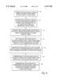
- a plurality of mini-digital optical nodes 36a, 36b, 36c, 36d, . . . 36nare connected to the feeder/de/multiplexing point 28 via pairs of downstream optic fibers 38a, 38b, 38c, 38d, . . . 38n and upstream optic fibers 40a, 40b, 40c, 40d, . . . 40n, respectively.
- Each pair of downstream and upstream optic fibers, e.g. 38a, 40aare substantially parallel to each other.
- the other branchesmay use the same or similar structure, implementation, and operation.
- mini-digital optical nodecan be replaced by a standard Personal Communication Station (PCS) base station.
- PCSPersonal Communication Station
Landscapes
- Engineering & Computer Science (AREA)
- Signal Processing (AREA)
- Computer Networks & Wireless Communication (AREA)
- Computing Systems (AREA)
- Physics & Mathematics (AREA)
- Electromagnetism (AREA)
- Multimedia (AREA)
- Optical Communication System (AREA)
Abstract
Description
Claims (28)
Priority Applications (3)
| Application Number | Priority Date | Filing Date | Title |
|---|---|---|---|
| US09/027,259US6147786A (en) | 1998-02-20 | 1998-02-20 | Hybrid analog/digital WDM access network with mini-digital optical node |
| PCT/US1999/003310WO1999043108A1 (en) | 1998-02-20 | 1999-02-18 | Hybrid analog/digital wdm access network with mini-digital optical node |
| AU26823/99AAU2682399A (en) | 1998-02-20 | 1999-02-18 | Hybrid analog/digital wdm access network with mini-digital optical node |
Applications Claiming Priority (1)
| Application Number | Priority Date | Filing Date | Title |
|---|---|---|---|
| US09/027,259US6147786A (en) | 1998-02-20 | 1998-02-20 | Hybrid analog/digital WDM access network with mini-digital optical node |
Publications (1)
| Publication Number | Publication Date |
|---|---|
| US6147786Atrue US6147786A (en) | 2000-11-14 |
Family
ID=21836637
Family Applications (1)
| Application Number | Title | Priority Date | Filing Date |
|---|---|---|---|
| US09/027,259Expired - LifetimeUS6147786A (en) | 1998-02-20 | 1998-02-20 | Hybrid analog/digital WDM access network with mini-digital optical node |
Country Status (3)
| Country | Link |
|---|---|
| US (1) | US6147786A (en) |
| AU (1) | AU2682399A (en) |
| WO (1) | WO1999043108A1 (en) |
Cited By (52)
| Publication number | Priority date | Publication date | Assignee | Title |
|---|---|---|---|---|
| US20010017722A1 (en)* | 2000-02-21 | 2001-08-30 | Noboru Takachio | Node apparatus, optical wavelength division multiplexing network, and system switching method |
| US20010028488A1 (en)* | 1999-12-27 | 2001-10-11 | Kim Byoung Whi | Internet protocol over WDM network, and packet communication system and method in the IPOW network |
| US20020018260A1 (en)* | 2000-06-01 | 2002-02-14 | Jean-Francis Kisovec | Multimedia optical community area network |
| US6490727B1 (en)* | 1999-10-07 | 2002-12-03 | Harmonic, Inc. | Distributed termination system for two-way hybrid networks |
| US20020188953A1 (en)* | 2001-06-06 | 2002-12-12 | Kevin Kenworthy | Centralized aggregation of broadcast television programming and multi-market digital delivery thereof over interconnected terrestrial fiber optic networks |
| US20020196490A1 (en)* | 2001-06-25 | 2002-12-26 | Corvis Corporation | Optical transmission systems, devices, and methods |
| US20030030871A1 (en)* | 2001-08-13 | 2003-02-13 | Dove Donald C. | Diversley routed fault tolerant optical node |
| US6523177B1 (en)* | 1999-04-01 | 2003-02-18 | Scientific-Atlanta, Inc. | Cable television system with digital reverse path architecture |
| US6654563B1 (en)* | 1999-02-17 | 2003-11-25 | At&T Corp. | Fiber/wired communication system |
| US6674967B2 (en)* | 2001-11-14 | 2004-01-06 | Scientific-Atlanta, Inc. | Fiber-to-the-home (FTTH) optical receiver having gain control and a remote enable |
| US6704545B1 (en)* | 2000-07-19 | 2004-03-09 | Adc Telecommunications, Inc. | Point-to-multipoint digital radio frequency transport |
| US20040106435A1 (en)* | 2002-12-03 | 2004-06-03 | Adc Telecommunications, Inc. | Distributed digital antenna system |
| US6751417B1 (en)* | 1999-02-17 | 2004-06-15 | At&T Corp. | Fiber and wire communication system |
| US6757522B1 (en)* | 2000-12-11 | 2004-06-29 | Cisco Technology, Inc. | Technique for determining carrier-to-noise ratio of selected channels in an access network |
| US6760550B2 (en)* | 2000-01-11 | 2004-07-06 | Aurora Networks | Reverse digitized communications architecture |
| US20040133920A1 (en)* | 2002-12-18 | 2004-07-08 | Yongtae Kim | Digital broadcast system in passive optical network |
| US6782206B1 (en) | 2000-11-27 | 2004-08-24 | Golden Bloom Resources, Ltd. | Multi-port optical node |
| US20040175173A1 (en)* | 2003-03-07 | 2004-09-09 | Sbc, Inc. | Method and system for delivering broadband services over an ultrawide band radio system integrated with a passive optical network |
| US20050286556A1 (en)* | 2004-06-14 | 2005-12-29 | Oleh Sniezko | Forward baseband digitalization |
| US7034975B1 (en) | 2001-12-03 | 2006-04-25 | Cheetah Onmi, Llc | High speed MEMS device |
| US20060104197A1 (en)* | 2000-02-24 | 2006-05-18 | Proctor James A Jr | Method and system for economical beam forming in a radio communication system |
| US7068937B1 (en) | 1999-02-17 | 2006-06-27 | At&T Corp. | Fiber and wire communication system |
| US7110671B1 (en) | 2001-12-03 | 2006-09-19 | Cheetah Omni, Llc | Method and apparatus for scheduling communication using a star switching fabric |
| US7209657B1 (en) | 2001-12-03 | 2007-04-24 | Cheetah Omni, Llc | Optical routing using a star switching fabric |
| US7260655B1 (en) | 2001-12-03 | 2007-08-21 | Cheetah Omni, Llc | Optical routing using star switching fabric with reduced effective switching time |
| US7283749B1 (en) | 1999-02-17 | 2007-10-16 | At&T Corp. | Fiber and wire communication system |
| US20070274730A1 (en)* | 2004-06-22 | 2007-11-29 | Han-Seung Koo | Onu And Method For Converting/Combining Frequency, And Apparatus And Method For Converting/Combining Frequency In Catv Headend System |
| US20080014948A1 (en)* | 2006-07-14 | 2008-01-17 | Lgc Wireless, Inc. | System for and method of for providing dedicated capacity in a cellular network |
| US7522836B2 (en) | 2001-02-02 | 2009-04-21 | Cheetah Omni, Llc | Optical logic gate based optical router |
| US20090154926A1 (en)* | 2007-12-12 | 2009-06-18 | Martin Birk | Highly reliable backbone video distribution architecture |
| US7599711B2 (en) | 2006-04-12 | 2009-10-06 | Adc Telecommunications, Inc. | Systems and methods for analog transport of RF voice/data communications |
| US7805073B2 (en) | 2006-04-28 | 2010-09-28 | Adc Telecommunications, Inc. | Systems and methods of optical path protection for distributed antenna systems |
| US7817958B2 (en) | 2006-12-22 | 2010-10-19 | Lgc Wireless Inc. | System for and method of providing remote coverage area for wireless communications |
| US7848770B2 (en) | 2006-08-29 | 2010-12-07 | Lgc Wireless, Inc. | Distributed antenna communications system and methods of implementing thereof |
| US20110026930A1 (en)* | 2009-07-29 | 2011-02-03 | Zhi Cui | Methods and apparatus to upgrade communication services in subscriber distribution areas |
| US7962111B2 (en) | 2002-02-25 | 2011-06-14 | ADC Wireless, Inc. | Distributed automatic gain control system |
| US8005050B2 (en) | 2007-03-23 | 2011-08-23 | Lgc Wireless, Inc. | Localization of a mobile device in distributed antenna communications system |
| US8010116B2 (en) | 2007-06-26 | 2011-08-30 | Lgc Wireless, Inc. | Distributed antenna communications system |
| US8032016B1 (en)* | 2002-02-13 | 2011-10-04 | Arris Group, Inc. | Agile block downconversion for the distribution of narrowcast services |
| US8285292B1 (en)* | 2000-02-11 | 2012-10-09 | At&T Mobility Ii Llc | Detection of cross-connection between a wireless loop network and another loop network at a subscriber's premises |
| US8554076B1 (en)* | 1999-10-04 | 2013-10-08 | At&T Intellectual Property Ii, L.P. | Methods and systems for constructing optical networks |
| US8583100B2 (en) | 2007-01-25 | 2013-11-12 | Adc Telecommunications, Inc. | Distributed remote base station system |
| US8737454B2 (en) | 2007-01-25 | 2014-05-27 | Adc Telecommunications, Inc. | Modular wireless communications platform |
| US20140186037A1 (en)* | 2012-12-30 | 2014-07-03 | Telefonaktiebolaget L M Ericsson (Publ) | Optical port discovery in a wdm optical network |
| US8908607B2 (en) | 2012-10-31 | 2014-12-09 | Andrew Llc | Digital baseband transport in telecommunications distribution systems |
| US9001811B2 (en) | 2009-05-19 | 2015-04-07 | Adc Telecommunications, Inc. | Method of inserting CDMA beacon pilots in output of distributed remote antenna nodes |
| US9014562B2 (en) | 1998-12-14 | 2015-04-21 | Coriant Operations, Inc. | Optical line terminal arrangement, apparatus and methods |
| US9112547B2 (en) | 2007-08-31 | 2015-08-18 | Adc Telecommunications, Inc. | System for and method of configuring distributed antenna communications system |
| US9577922B2 (en) | 2014-02-18 | 2017-02-21 | Commscope Technologies Llc | Selectively combining uplink signals in distributed antenna systems |
| US9826410B2 (en) | 2009-04-29 | 2017-11-21 | Commscope Technologies Llc | Distributed antenna system for wireless network systems |
| US10499269B2 (en) | 2015-11-12 | 2019-12-03 | Commscope Technologies Llc | Systems and methods for assigning controlled nodes to channel interfaces of a controller |
| US20220311516A1 (en)* | 2019-07-16 | 2022-09-29 | Sumitomo Electric Industries, Ltd. | Optical network system and automatic operation system |
Families Citing this family (1)
| Publication number | Priority date | Publication date | Assignee | Title |
|---|---|---|---|---|
| US7844182B2 (en) | 2003-09-12 | 2010-11-30 | Aurora Networks, Inc. | Optical network architecture for simultaneous transport of analog video signals and ethernet data |
Citations (7)
| Publication number | Priority date | Publication date | Assignee | Title |
|---|---|---|---|---|
| US5136411A (en)* | 1987-12-11 | 1992-08-04 | General Instrument Corporation | Dynamically responsive CATV system with shared fiber optic link |
| US5202780A (en)* | 1989-04-22 | 1993-04-13 | Alcatel N.V. | Optical communication system for the subscriber area |
| EP0703681A2 (en)* | 1994-09-22 | 1996-03-27 | Siemens Aktiengesellschaft | Optical subscriber network for the combined transmission of subscriber signals and of video or audio broadcast signals |
| EP0782285A2 (en)* | 1995-12-28 | 1997-07-02 | AT&T Corp. | Multiple star, passive optical network based on remote interrogation of terminal equipment |
| US5864415A (en)* | 1996-05-30 | 1999-01-26 | Bell Atlantic Network Services, Inc. | Fiber optic network with wavelength-division-multiplexed transmission to customer premises |
| US5864748A (en)* | 1996-09-18 | 1999-01-26 | At&T Corp. | Hybrid fiber-coax system having at least one digital fiber node and increased upstream and downstream bandwidth |
| US5911019A (en)* | 1997-09-04 | 1999-06-08 | Lucent Technologies Inc. | Method for upgrading a hybrid fiber coax network to an all fiber network |
- 1998
- 1998-02-20USUS09/027,259patent/US6147786A/ennot_activeExpired - Lifetime
- 1999
- 1999-02-18AUAU26823/99Apatent/AU2682399A/ennot_activeAbandoned
- 1999-02-18WOPCT/US1999/003310patent/WO1999043108A1/enactiveApplication Filing
Patent Citations (8)
| Publication number | Priority date | Publication date | Assignee | Title |
|---|---|---|---|---|
| US5136411A (en)* | 1987-12-11 | 1992-08-04 | General Instrument Corporation | Dynamically responsive CATV system with shared fiber optic link |
| US5202780A (en)* | 1989-04-22 | 1993-04-13 | Alcatel N.V. | Optical communication system for the subscriber area |
| EP0703681A2 (en)* | 1994-09-22 | 1996-03-27 | Siemens Aktiengesellschaft | Optical subscriber network for the combined transmission of subscriber signals and of video or audio broadcast signals |
| EP0782285A2 (en)* | 1995-12-28 | 1997-07-02 | AT&T Corp. | Multiple star, passive optical network based on remote interrogation of terminal equipment |
| US5808764A (en)* | 1995-12-28 | 1998-09-15 | Lucent Technologies, Inc. | Multiple star, passive optical network based on remote interrogation of terminal equipment |
| US5864415A (en)* | 1996-05-30 | 1999-01-26 | Bell Atlantic Network Services, Inc. | Fiber optic network with wavelength-division-multiplexed transmission to customer premises |
| US5864748A (en)* | 1996-09-18 | 1999-01-26 | At&T Corp. | Hybrid fiber-coax system having at least one digital fiber node and increased upstream and downstream bandwidth |
| US5911019A (en)* | 1997-09-04 | 1999-06-08 | Lucent Technologies Inc. | Method for upgrading a hybrid fiber coax network to an all fiber network |
Cited By (110)
| Publication number | Priority date | Publication date | Assignee | Title |
|---|---|---|---|---|
| US9014562B2 (en) | 1998-12-14 | 2015-04-21 | Coriant Operations, Inc. | Optical line terminal arrangement, apparatus and methods |
| US7190903B1 (en)* | 1999-02-17 | 2007-03-13 | At&T Corp. | Fiber and wire communication system |
| US7734179B1 (en) | 1999-02-17 | 2010-06-08 | At&T Corp. | Fiber/wired communication system |
| US7068937B1 (en) | 1999-02-17 | 2006-06-27 | At&T Corp. | Fiber and wire communication system |
| US20090067841A1 (en)* | 1999-02-17 | 2009-03-12 | Combs Charles D | Fiber and wire communication system |
| US7450850B2 (en) | 1999-02-17 | 2008-11-11 | At&T Corp. | Fiber and wire communication system |
| US7783196B2 (en) | 1999-02-17 | 2010-08-24 | At&T Intellectual Property Ii, L.P. | Fiber and wire communication system |
| US6751417B1 (en)* | 1999-02-17 | 2004-06-15 | At&T Corp. | Fiber and wire communication system |
| US20070166036A1 (en)* | 1999-02-17 | 2007-07-19 | Combs Charles D | Fiber and wire communication system |
| US6654563B1 (en)* | 1999-02-17 | 2003-11-25 | At&T Corp. | Fiber/wired communication system |
| US20080019695A1 (en)* | 1999-02-17 | 2008-01-24 | Combs Charles D | Fiber and wire communication system |
| US7831147B2 (en) | 1999-02-17 | 2010-11-09 | At&T Intellectual Property Ii, L.P. | Fiber and wire communication system |
| US7283749B1 (en) | 1999-02-17 | 2007-10-16 | At&T Corp. | Fiber and wire communication system |
| US20030056227A1 (en)* | 1999-04-01 | 2003-03-20 | Farhan Fariborz M. | Cable television system with digital reverse path architecture |
| US6523177B1 (en)* | 1999-04-01 | 2003-02-18 | Scientific-Atlanta, Inc. | Cable television system with digital reverse path architecture |
| US8554076B1 (en)* | 1999-10-04 | 2013-10-08 | At&T Intellectual Property Ii, L.P. | Methods and systems for constructing optical networks |
| US6490727B1 (en)* | 1999-10-07 | 2002-12-03 | Harmonic, Inc. | Distributed termination system for two-way hybrid networks |
| US20010028488A1 (en)* | 1999-12-27 | 2001-10-11 | Kim Byoung Whi | Internet protocol over WDM network, and packet communication system and method in the IPOW network |
| US6952533B2 (en)* | 1999-12-27 | 2005-10-04 | Electronics And Telecommunications Research Institute | Internet protocol over WDM network, and packet communication system and method in the IPOW network |
| US6760550B2 (en)* | 2000-01-11 | 2004-07-06 | Aurora Networks | Reverse digitized communications architecture |
| US8285292B1 (en)* | 2000-02-11 | 2012-10-09 | At&T Mobility Ii Llc | Detection of cross-connection between a wireless loop network and another loop network at a subscriber's premises |
| US7164861B2 (en)* | 2000-02-21 | 2007-01-16 | Nippon Telegraph And Telephone Corporation | Node apparatus, optical wavelength division multiplexing network, and system switching method |
| US20070031146A1 (en)* | 2000-02-21 | 2007-02-08 | Nippon Telegraph And Telephone Corporation | Node apparatus, optical wavelength division multiplexing network, and system switching method |
| US7433594B2 (en)* | 2000-02-21 | 2008-10-07 | Nippon Telegraph And Telephone Corporation | Node apparatus, optical wavelength division multiplexing network, and system switching method |
| US20010017722A1 (en)* | 2000-02-21 | 2001-08-30 | Noboru Takachio | Node apparatus, optical wavelength division multiplexing network, and system switching method |
| US20060104197A1 (en)* | 2000-02-24 | 2006-05-18 | Proctor James A Jr | Method and system for economical beam forming in a radio communication system |
| US20020018260A1 (en)* | 2000-06-01 | 2002-02-14 | Jean-Francis Kisovec | Multimedia optical community area network |
| US6704545B1 (en)* | 2000-07-19 | 2004-03-09 | Adc Telecommunications, Inc. | Point-to-multipoint digital radio frequency transport |
| US10505635B2 (en) | 2000-07-19 | 2019-12-10 | Commscope Technologies Llc | Point-to-multipoint digital radio frequency transport |
| US8577286B2 (en) | 2000-07-19 | 2013-11-05 | Adc Telecommunications, Inc. | Point-to-multipoint digital radio frequency transport |
| US8326218B2 (en) | 2000-07-19 | 2012-12-04 | Adc Telecommunications, Inc. | Point-to-multipoint digital radio frequency transport |
| US20100061291A1 (en)* | 2000-07-19 | 2010-03-11 | Adc Telecommunications, Inc. | Point-to-multipoint digital radio frequency transport |
| US7639982B2 (en) | 2000-07-19 | 2009-12-29 | Adc Telecommunications, Inc. | Point-to-multipoint digital radio frequency transport |
| US9332402B2 (en) | 2000-07-19 | 2016-05-03 | Commscope Technologies Llc | Point-to-multipoint digital radio frequency transport |
| US20040132474A1 (en)* | 2000-07-19 | 2004-07-08 | Adc Telecommunications, Inc. | Point-to-multipoint digital radio frequency transport |
| US10498434B2 (en) | 2000-07-19 | 2019-12-03 | CommScope Technolgies LLC | Point-to-multipoint digital radio frequency transport |
| US6782206B1 (en) | 2000-11-27 | 2004-08-24 | Golden Bloom Resources, Ltd. | Multi-port optical node |
| US6757522B1 (en)* | 2000-12-11 | 2004-06-29 | Cisco Technology, Inc. | Technique for determining carrier-to-noise ratio of selected channels in an access network |
| US7522836B2 (en) | 2001-02-02 | 2009-04-21 | Cheetah Omni, Llc | Optical logic gate based optical router |
| US20040255333A1 (en)* | 2001-06-06 | 2004-12-16 | Kevin Kenworthy | Centralized aggregation of broadcast television programming and multi-market digital delivery thereof over interconnected terrestrial fiber optic networks |
| US20020188953A1 (en)* | 2001-06-06 | 2002-12-12 | Kevin Kenworthy | Centralized aggregation of broadcast television programming and multi-market digital delivery thereof over interconnected terrestrial fiber optic networks |
| US7769290B2 (en)* | 2001-06-25 | 2010-08-03 | Broadwing Corporation | Optical transmission systems, devices, and methods |
| US8064763B2 (en) | 2001-06-25 | 2011-11-22 | Level 3 Communications, Llc | Optical transmission systems, devices, and methods |
| US20020196490A1 (en)* | 2001-06-25 | 2002-12-26 | Corvis Corporation | Optical transmission systems, devices, and methods |
| US20030030871A1 (en)* | 2001-08-13 | 2003-02-13 | Dove Donald C. | Diversley routed fault tolerant optical node |
| EP1454432A4 (en)* | 2001-11-14 | 2006-08-02 | Scientific Atlanta | Fiber-to-the-home (ftth) optical receiver having gain control and a remote enable |
| US6674967B2 (en)* | 2001-11-14 | 2004-01-06 | Scientific-Atlanta, Inc. | Fiber-to-the-home (FTTH) optical receiver having gain control and a remote enable |
| US20070036546A1 (en)* | 2001-12-03 | 2007-02-15 | Cheetah Omni, Llc | Method and Apparatus for Scheduling Communication using a Star Switching Fabric |
| US7260655B1 (en) | 2001-12-03 | 2007-08-21 | Cheetah Omni, Llc | Optical routing using star switching fabric with reduced effective switching time |
| US7110671B1 (en) | 2001-12-03 | 2006-09-19 | Cheetah Omni, Llc | Method and apparatus for scheduling communication using a star switching fabric |
| US7209657B1 (en) | 2001-12-03 | 2007-04-24 | Cheetah Omni, Llc | Optical routing using a star switching fabric |
| US7305186B2 (en) | 2001-12-03 | 2007-12-04 | Cheetah Omni, Llc | Method and apparatus for scheduling communication using a star switching fabric |
| US7263288B1 (en) | 2001-12-03 | 2007-08-28 | Cheetah Omni, Llc | Optical routing using a star switching fabric |
| US7034975B1 (en) | 2001-12-03 | 2006-04-25 | Cheetah Onmi, Llc | High speed MEMS device |
| US8032016B1 (en)* | 2002-02-13 | 2011-10-04 | Arris Group, Inc. | Agile block downconversion for the distribution of narrowcast services |
| US9094149B1 (en) | 2002-02-13 | 2015-07-28 | Arris Enterprises, Inc. | Media stream distribution system |
| US7962111B2 (en) | 2002-02-25 | 2011-06-14 | ADC Wireless, Inc. | Distributed automatic gain control system |
| US20040106435A1 (en)* | 2002-12-03 | 2004-06-03 | Adc Telecommunications, Inc. | Distributed digital antenna system |
| US8958789B2 (en) | 2002-12-03 | 2015-02-17 | Adc Telecommunications, Inc. | Distributed digital antenna system |
| USRE49377E1 (en) | 2002-12-03 | 2023-01-17 | Commscope Technologies Llc | Distributed digital antenna system |
| USRE50112E1 (en) | 2002-12-03 | 2024-09-03 | Outdoor Wireless Networks LLC | Distributed digital antenna system |
| US20040133920A1 (en)* | 2002-12-18 | 2004-07-08 | Yongtae Kim | Digital broadcast system in passive optical network |
| US7610608B2 (en)* | 2002-12-18 | 2009-10-27 | Electronics And Telecommunications Research Institute | Digital broadcast system in passive optical network |
| US20040175173A1 (en)* | 2003-03-07 | 2004-09-09 | Sbc, Inc. | Method and system for delivering broadband services over an ultrawide band radio system integrated with a passive optical network |
| US7962042B2 (en) | 2003-03-07 | 2011-06-14 | At&T Intellectual Property I, L.P. | Method and system for delivering broadband services over an ultrawide band radio system integrated with a passive optical network |
| US20050286556A1 (en)* | 2004-06-14 | 2005-12-29 | Oleh Sniezko | Forward baseband digitalization |
| US7706689B2 (en) | 2004-06-14 | 2010-04-27 | Aurora Networks, Inc. | Forward baseband digitalization |
| US20070274730A1 (en)* | 2004-06-22 | 2007-11-29 | Han-Seung Koo | Onu And Method For Converting/Combining Frequency, And Apparatus And Method For Converting/Combining Frequency In Catv Headend System |
| US7669224B2 (en)* | 2004-06-22 | 2010-02-23 | Electronic And Telecommunications Research Institute | ONU and method for converting/combining frequency, and apparatus and method for converting/combining frequency in CATV headend system |
| US7599711B2 (en) | 2006-04-12 | 2009-10-06 | Adc Telecommunications, Inc. | Systems and methods for analog transport of RF voice/data communications |
| US10411805B2 (en) | 2006-04-28 | 2019-09-10 | Commscope Technologies Llc | Systems and methods of optical path protection for distributed antenna systems |
| US8135273B2 (en) | 2006-04-28 | 2012-03-13 | Adc Telecommunications, Inc. | Systems and methods of optical path protection for distributed antenna systems |
| US20110002687A1 (en)* | 2006-04-28 | 2011-01-06 | Adc Telecommunications, Inc. | Systems and methods of optical path protection for distributed antenna systems |
| US9843391B2 (en) | 2006-04-28 | 2017-12-12 | Commscope Technologies Llc | Systems and methods of optical path protection for distributed antenna systems |
| US7805073B2 (en) | 2006-04-28 | 2010-09-28 | Adc Telecommunications, Inc. | Systems and methods of optical path protection for distributed antenna systems |
| US8805182B2 (en) | 2006-04-28 | 2014-08-12 | Adc Telecommunications Inc. | Systems and methods of optical path protection for distributed antenna systems |
| US7844273B2 (en) | 2006-07-14 | 2010-11-30 | Lgc Wireless, Inc. | System for and method of for providing dedicated capacity in a cellular network |
| US20080014948A1 (en)* | 2006-07-14 | 2008-01-17 | Lgc Wireless, Inc. | System for and method of for providing dedicated capacity in a cellular network |
| US7848770B2 (en) | 2006-08-29 | 2010-12-07 | Lgc Wireless, Inc. | Distributed antenna communications system and methods of implementing thereof |
| US7817958B2 (en) | 2006-12-22 | 2010-10-19 | Lgc Wireless Inc. | System for and method of providing remote coverage area for wireless communications |
| US9941921B2 (en) | 2007-01-25 | 2018-04-10 | Commscope Technologies Llc | Modular wireless communications platform |
| US8737454B2 (en) | 2007-01-25 | 2014-05-27 | Adc Telecommunications, Inc. | Modular wireless communications platform |
| US10554242B2 (en) | 2007-01-25 | 2020-02-04 | Commscope Technologies Llc | Modular wireless communications platform |
| US8583100B2 (en) | 2007-01-25 | 2013-11-12 | Adc Telecommunications, Inc. | Distributed remote base station system |
| US9585193B2 (en) | 2007-01-25 | 2017-02-28 | Commscope Technologies Llc | Modular wireless communications platform |
| US8005050B2 (en) | 2007-03-23 | 2011-08-23 | Lgc Wireless, Inc. | Localization of a mobile device in distributed antenna communications system |
| USRE45505E1 (en) | 2007-03-23 | 2015-05-05 | Adc Telecommunications, Inc. | Localization of a mobile device in distributed antenna communications system |
| US8532698B2 (en) | 2007-06-26 | 2013-09-10 | Adc Telecommunications, Inc. | Distributed antenna communications system |
| US8229497B2 (en) | 2007-06-26 | 2012-07-24 | Lgc Wireless, Llc | Distributed antenna communications system |
| US8010116B2 (en) | 2007-06-26 | 2011-08-30 | Lgc Wireless, Inc. | Distributed antenna communications system |
| US9112547B2 (en) | 2007-08-31 | 2015-08-18 | Adc Telecommunications, Inc. | System for and method of configuring distributed antenna communications system |
| US20090154926A1 (en)* | 2007-12-12 | 2009-06-18 | Martin Birk | Highly reliable backbone video distribution architecture |
| US9826410B2 (en) | 2009-04-29 | 2017-11-21 | Commscope Technologies Llc | Distributed antenna system for wireless network systems |
| US10499253B2 (en) | 2009-04-29 | 2019-12-03 | Commscope Technologies Llc | Distributed antenna system for wireless network systems |
| US9001811B2 (en) | 2009-05-19 | 2015-04-07 | Adc Telecommunications, Inc. | Method of inserting CDMA beacon pilots in output of distributed remote antenna nodes |
| US9736022B2 (en)* | 2009-07-29 | 2017-08-15 | At&T Intellectual Property I, L.P. | Methods and apparatus to upgrade communication services in subscriber distribution areas |
| US20110026930A1 (en)* | 2009-07-29 | 2011-02-03 | Zhi Cui | Methods and apparatus to upgrade communication services in subscriber distribution areas |
| US20160149756A1 (en)* | 2009-07-29 | 2016-05-26 | At&T Intellectual Property I, L.P. | Methods and apparatus to upgrade communication services in subscriber distribution areas |
| US11419119B2 (en) | 2012-10-31 | 2022-08-16 | Commscope Technologies Llc | Digital baseband transport in telecommunications distribution systems |
| US9967885B2 (en) | 2012-10-31 | 2018-05-08 | Commscope Technologies Llc | Digital baseband transport in telecommunications distribution systems |
| US10841923B2 (en) | 2012-10-31 | 2020-11-17 | Commscope Technologies Llc | Digital baseband transport in telecommunications distribution systems |
| US8908607B2 (en) | 2012-10-31 | 2014-12-09 | Andrew Llc | Digital baseband transport in telecommunications distribution systems |
| US9462603B2 (en) | 2012-10-31 | 2016-10-04 | Commscope Technologies Llc | Digital baseband transport in telecommunications distribution systems |
| US8811820B2 (en)* | 2012-12-30 | 2014-08-19 | Telefonaktiebolaget L M Ericsson (Publ) | Optical port discovery in a WDM optical network |
| US20140186037A1 (en)* | 2012-12-30 | 2014-07-03 | Telefonaktiebolaget L M Ericsson (Publ) | Optical port discovery in a wdm optical network |
| US9577922B2 (en) | 2014-02-18 | 2017-02-21 | Commscope Technologies Llc | Selectively combining uplink signals in distributed antenna systems |
| US10291295B2 (en) | 2014-02-18 | 2019-05-14 | Commscope Technologies Llc | Selectively combining uplink signals in distributed antenna systems |
| US10499269B2 (en) | 2015-11-12 | 2019-12-03 | Commscope Technologies Llc | Systems and methods for assigning controlled nodes to channel interfaces of a controller |
| US20220311516A1 (en)* | 2019-07-16 | 2022-09-29 | Sumitomo Electric Industries, Ltd. | Optical network system and automatic operation system |
| US11863235B2 (en)* | 2019-07-16 | 2024-01-02 | Sumitomo Electric Industries, Ltd. | Optical network system and automatic operation system |
Also Published As
| Publication number | Publication date |
|---|---|
| AU2682399A (en) | 1999-09-06 |
| WO1999043108A1 (en) | 1999-08-26 |
Similar Documents
| Publication | Publication Date | Title |
|---|---|---|
| US6147786A (en) | Hybrid analog/digital WDM access network with mini-digital optical node | |
| US7499651B2 (en) | Upgradeable passive optical network | |
| US7684705B2 (en) | Distribution node for a wavelength-sharing network | |
| US7546036B2 (en) | Hybrid passive optical network using shared wavelengths | |
| Ramaswami | Multiwavelength lightwave networks for computer communication | |
| US7522838B2 (en) | Distribution components for a wavelength-sharing network | |
| US6895185B1 (en) | Multi-purpose optical fiber access network | |
| JP4520643B2 (en) | Optical communication network using frequency division multiplexing | |
| JP3484269B2 (en) | Communication network and operation method thereof | |
| US6452945B1 (en) | Electrical add-drop multiplexing for optical communications networks utilizing frequency division multiplexing | |
| US7684706B2 (en) | System and method for traffic distribution in an optical network | |
| KR100606102B1 (en) | Broadcast / communication integrated passive optical network system | |
| US7130541B2 (en) | System and method for communicating optical signals upstream and downstream between a data service provider and subscriber | |
| KR20070006767A (en) | Carrier Wavelength Division Multiplexing Passive Optical Network System and Device Accommodating Multiple Services or Protocols | |
| US20040264964A1 (en) | Deep fiber network with high speed data and video on demand | |
| US7606492B2 (en) | System and method for communicating optical signals upstream and downstream between a data service provider and subscribers | |
| Nooruzzaman et al. | Low-cost hybrid ROADM architectures for scalable C/DWDM metro networks | |
| US20070274724A1 (en) | Wavelength Selective Switch Design Configurations for Mesh Light-Trails | |
| JP3533370B2 (en) | Trunk node device and optical access network | |
| Frigo | Local access optical networks | |
| US20070292134A1 (en) | Unknown | |
| US7725029B1 (en) | Technique for asymmetric transport | |
| Olshansky et al. | Subcarrier multiplexed broad-band service network: A flexible platform for broad-band subscriber services | |
| US20030063847A1 (en) | Deep fiber network architecture | |
| WO2007021199A1 (en) | A method and system for polarized signalling in an optical switched network |
Legal Events
| Date | Code | Title | Description |
|---|---|---|---|
| AS | Assignment | Owner name:NOKIA TELECOMMUNICATIONS, OY, FINLAND Free format text:ASSIGNMENT OF ASSIGNORS INTEREST;ASSIGNOR:PAN, JIN-YI;REEL/FRAME:009012/0244 Effective date:19980218 | |
| AS | Assignment | Owner name:NOKIA TELECOMMUNICATIONS OY, FINLAND Free format text:CORRECTIVE ASSIGNMENT TO CORRECT THE ASSIGNEES ADDRESS, FILED ON 2-20-99 RECORDED ON REEL 9012 FRAME 0244;ASSIGNOR:PAN, JIN-YI;REEL/FRAME:009911/0189 Effective date:19980218 | |
| STCF | Information on status: patent grant | Free format text:PATENTED CASE | |
| FPAY | Fee payment | Year of fee payment:4 | |
| FEPP | Fee payment procedure | Free format text:PAYER NUMBER DE-ASSIGNED (ORIGINAL EVENT CODE: RMPN); ENTITY STATUS OF PATENT OWNER: LARGE ENTITY Free format text:PAYOR NUMBER ASSIGNED (ORIGINAL EVENT CODE: ASPN); ENTITY STATUS OF PATENT OWNER: LARGE ENTITY | |
| AS | Assignment | Owner name:NOKIA NETWORKS OY, FINLAND Free format text:CHANGE OF NAME;ASSIGNOR:NOKIA TELECOMMUNICATIONS OY;REEL/FRAME:020153/0519 Effective date:19991001 Owner name:NOKIA CORPORATION, FINLAND Free format text:MERGER;ASSIGNOR:NOKIA NETWORKS OY;REEL/FRAME:020153/0619 Effective date:20011001 Owner name:SCHOFIELD TECHNOLOGIES LLC, DELAWARE Free format text:ASSIGNMENT OF ASSIGNORS INTEREST;ASSIGNOR:NOKIA CORPORATION;REEL/FRAME:020153/0622 Effective date:20070625 | |
| FPAY | Fee payment | Year of fee payment:8 | |
| FEPP | Fee payment procedure | Free format text:PAYER NUMBER DE-ASSIGNED (ORIGINAL EVENT CODE: RMPN); ENTITY STATUS OF PATENT OWNER: LARGE ENTITY Free format text:PAYOR NUMBER ASSIGNED (ORIGINAL EVENT CODE: ASPN); ENTITY STATUS OF PATENT OWNER: LARGE ENTITY | |
| FPAY | Fee payment | Year of fee payment:12 | |
| AS | Assignment | Owner name:HANGER SOLUTIONS, LLC, GEORGIA Free format text:ASSIGNMENT OF ASSIGNORS INTEREST;ASSIGNOR:INTELLECTUAL VENTURES ASSETS 161 LLC;REEL/FRAME:052159/0509 Effective date:20191206 | |
| AS | Assignment | Owner name:INTELLECTUAL VENTURES ASSETS 161 LLC, DELAWARE Free format text:ASSIGNMENT OF ASSIGNORS INTEREST;ASSIGNOR:SCHOFIELD TECHNOLOGIES LLC;REEL/FRAME:051851/0343 Effective date:20191126 |