US6147761A - Color sensor - Google Patents
Color sensorDownload PDFInfo
- Publication number
- US6147761A US6147761AUS09/059,889US5988998AUS6147761AUS 6147761 AUS6147761 AUS 6147761AUS 5988998 AUS5988998 AUS 5988998AUS 6147761 AUS6147761 AUS 6147761A
- Authority
- US
- United States
- Prior art keywords
- sample
- light
- photodetector
- sensor
- light sources
- Prior art date
- Legal status (The legal status is an assumption and is not a legal conclusion. Google has not performed a legal analysis and makes no representation as to the accuracy of the status listed.)
- Expired - Lifetime
Links
Images


Classifications
- G—PHYSICS
- G01—MEASURING; TESTING
- G01J—MEASUREMENT OF INTENSITY, VELOCITY, SPECTRAL CONTENT, POLARISATION, PHASE OR PULSE CHARACTERISTICS OF INFRARED, VISIBLE OR ULTRAVIOLET LIGHT; COLORIMETRY; RADIATION PYROMETRY
- G01J3/00—Spectrometry; Spectrophotometry; Monochromators; Measuring colours
- G01J3/46—Measurement of colour; Colour measuring devices, e.g. colorimeters
- G—PHYSICS
- G01—MEASURING; TESTING
- G01J—MEASUREMENT OF INTENSITY, VELOCITY, SPECTRAL CONTENT, POLARISATION, PHASE OR PULSE CHARACTERISTICS OF INFRARED, VISIBLE OR ULTRAVIOLET LIGHT; COLORIMETRY; RADIATION PYROMETRY
- G01J3/00—Spectrometry; Spectrophotometry; Monochromators; Measuring colours
- G01J3/02—Details
- G01J3/0205—Optical elements not provided otherwise, e.g. optical manifolds, diffusers, windows
- G01J3/0251—Colorimeters making use of an integrating sphere
- G—PHYSICS
- G01—MEASURING; TESTING
- G01J—MEASUREMENT OF INTENSITY, VELOCITY, SPECTRAL CONTENT, POLARISATION, PHASE OR PULSE CHARACTERISTICS OF INFRARED, VISIBLE OR ULTRAVIOLET LIGHT; COLORIMETRY; RADIATION PYROMETRY
- G01J3/00—Spectrometry; Spectrophotometry; Monochromators; Measuring colours
- G01J3/46—Measurement of colour; Colour measuring devices, e.g. colorimeters
- G01J3/463—Colour matching
- G—PHYSICS
- G01—MEASURING; TESTING
- G01J—MEASUREMENT OF INTENSITY, VELOCITY, SPECTRAL CONTENT, POLARISATION, PHASE OR PULSE CHARACTERISTICS OF INFRARED, VISIBLE OR ULTRAVIOLET LIGHT; COLORIMETRY; RADIATION PYROMETRY
- G01J3/00—Spectrometry; Spectrophotometry; Monochromators; Measuring colours
- G01J3/46—Measurement of colour; Colour measuring devices, e.g. colorimeters
- G01J3/465—Measurement of colour; Colour measuring devices, e.g. colorimeters taking into account the colour perception of the eye; using tristimulus detection
- G—PHYSICS
- G01—MEASURING; TESTING
- G01J—MEASUREMENT OF INTENSITY, VELOCITY, SPECTRAL CONTENT, POLARISATION, PHASE OR PULSE CHARACTERISTICS OF INFRARED, VISIBLE OR ULTRAVIOLET LIGHT; COLORIMETRY; RADIATION PYROMETRY
- G01J3/00—Spectrometry; Spectrophotometry; Monochromators; Measuring colours
- G01J3/46—Measurement of colour; Colour measuring devices, e.g. colorimeters
- G01J3/50—Measurement of colour; Colour measuring devices, e.g. colorimeters using electric radiation detectors
- G01J3/501—Colorimeters using spectrally-selective light sources, e.g. LEDs
- G—PHYSICS
- G01—MEASURING; TESTING
- G01J—MEASUREMENT OF INTENSITY, VELOCITY, SPECTRAL CONTENT, POLARISATION, PHASE OR PULSE CHARACTERISTICS OF INFRARED, VISIBLE OR ULTRAVIOLET LIGHT; COLORIMETRY; RADIATION PYROMETRY
- G01J3/00—Spectrometry; Spectrophotometry; Monochromators; Measuring colours
- G01J3/46—Measurement of colour; Colour measuring devices, e.g. colorimeters
- G01J3/52—Measurement of colour; Colour measuring devices, e.g. colorimeters using colour charts
- G01J3/524—Calibration of colorimeters
- G—PHYSICS
- G01—MEASURING; TESTING
- G01J—MEASUREMENT OF INTENSITY, VELOCITY, SPECTRAL CONTENT, POLARISATION, PHASE OR PULSE CHARACTERISTICS OF INFRARED, VISIBLE OR ULTRAVIOLET LIGHT; COLORIMETRY; RADIATION PYROMETRY
- G01J3/00—Spectrometry; Spectrophotometry; Monochromators; Measuring colours
- G01J3/28—Investigating the spectrum
- G01J2003/2866—Markers; Calibrating of scan
- G—PHYSICS
- G01—MEASURING; TESTING
- G01J—MEASUREMENT OF INTENSITY, VELOCITY, SPECTRAL CONTENT, POLARISATION, PHASE OR PULSE CHARACTERISTICS OF INFRARED, VISIBLE OR ULTRAVIOLET LIGHT; COLORIMETRY; RADIATION PYROMETRY
- G01J3/00—Spectrometry; Spectrophotometry; Monochromators; Measuring colours
- G01J3/02—Details
- G01J3/0272—Handheld
Definitions
- the present inventionrelates generally to devices for measuring reflective, transmissive, or self-luminous samples and reporting their spectrophotometric, spectroradiometric, densitometric, or other colorimetric appearance attributes.
- the inputting of colors represented by physical samples into an electronic design for display and printingis currently a tedious process.
- the end-userhas several options.
- the samplemay be scanned, but the color reproduction will be poor for the reasons discussed above.
- the samplemay be visually matched by specifying. RGB or CMYK amounts for the application, but the match will be device dependent and highly variable.
- a color specification systemmay be employed by visually matching the sample to one of the specified colors then entering the color specification to the application, but the match will be device dependent, highly variable, and rely upon application compatibility with the color specification system.
- CMSsoftware-based color management system
- a simple work flow for such a CMSmight be comprised of the following steps: (1) the image scan (Scanner RGB) is referenced to CIE; (2) the image is converted to Display RGB for editing; (3) the displayed image is referenced back to CIE; and (4) the image is converted to printer CMYK for output.
- the CMS vendorprovides several key elements: a library of device characterization profiles, a color matching method, and color transformation software. Since the expertise and equipment required for the creation of profiles is expensive, device characterization is performed by the CMS vendor for an average device for average viewing conditions. Unfortunately, characterization accomplished in this manner is done under factory conditions and not for the end-user conditions (device, light source, media, viewing, etc.). Since an end-user's device will be quite different from the device that was profiled at the factory, some vendors offer hardware/software calibration. Calibration only partially compensates for the differences between factory conditions and end-user conditions but does not satisfy the need for end-user device characterization compatible with open architecture CMS.
- CMS productsare generally proprietary and must be purchased from the CMS vendor.
- open architecture CMS technologywill be included as part of the operating system, device manufacturers, third parties, and end-users will require custom CMMs or profiles.
- CMS technologyfactory characterization, and end-user calibration improves the average color reproduction on the desktop somewhat, but is expensive, complex, and does not meet the end-user requirements for quality, cost, speed, and compatibility.
- End-usersneed a fast, low-cost, simple hardware/software characterizor enabling them to easily characterize (not just calibrate) their specific scanners, monitors, and printers to their specific viewing conditions in a manner that is compatible with open architecture CMS technology.
- U.S. Pat. No. 5,137,364discloses a color sensor that employs a plurality of LEDs (light emitting diodes) and an array of photodetectors.
- the McCarthy sensorutilizes individually addressable, customized LEDs as its illumination sources and a photodetector array, where each photodetector measures reflectance of the sample at a different visible wavelength, and where each element's spectral sensitivity must be individually optimized.
- the McCarthy sensoralso utilizes a single beam reflectance measurement scheme.
- the photodetectorsmust be made as stable as possible by maintaining at a constant temperature and being protected from humidity; etc.
- the McCarthy devicerequires expensive and stable components since the measured energy collected from the color sample must be constant. Such expensive and customized components nevertheless may also, experience long term drift and may be highly sensitive to noise.
- U.S. Pat. No. 5,377,000 to Berendsdiscloses a color sensor that utilizes a single illumination source positioned directly above the sample, 21 sample photodetectors arranged circumferentially around the illumination source and positioned at 45° angles with respect to the sample, and 2 reference photodetectors positioned to receive light directed from the single illumination source.
- Berendsutilizes a "pseudo-dual beam" reflectance measurement scheme in an attempt to eliminate the need of an additional 19 reference photodetectors that would be required in a classic dual-beam reflectance measurement scheme. This is performed by configuring the 2 reference photodetectors to sample the illumination source at opposite extremes of the visible light. spectrum, and by applying a "least squares fit" calibration calculation to simulate the required 21 reference channel readings.
- the present inventionprovides an extremely accurate color sensor, designed to utilize a classic dual-beam reflectance measurement scheme with inexpensive and commercially available components.
- a device for measuring reflective, transmissive, or self-luminous samplescomprises: a plurality of light sources, which are preferably light emitting diodes (LEDs), where each of the light sources emit light of a substantially different wavelength band spaced in the visible spectrum; a reference channel photodetector; a sample channel photodetector; an optical cap adapted to direct a first portion of the light emitted by each of the light sources to the reference channel photodetector; a reflector cone for directing a second portion of the light emitted by each of the light sources to the sample; and a receptor piece for directing the diffuse portion of the light reflected from the sample to the sample channel photodetector.
- LEDslight emitting diodes
- the reference channel and sample channel photodetectorsare identical devices and are mounted back-to-back to share environmental characteristics, and in turn, minimize the variation between their respective responses.
- the output signals from the photodetectorsare processed to provide at least one appearance value, e.g., spectrophotometric, spectroradiometric, densitometric, and other calorimetric appearance attributes for the samples.
- the optical caphas a non-absorbing interior integrating surface and is mounted over the LEDs and the reference photodetector such that the reference portion of light generated by the emitters reflects off of the integrating surface to the reference photodetector.
- the LEDsare each preferably mounted such that a portion of each LED extends into a cylindrical cavity pointing downwards towards the sample, the cavities acting to collimate the sample portion of light emitted by the LEDs.
- the reflector conepreferably has a conical reflecting surface, positioned in alignment with the cavities, and angled 22.5° with respect to the cavities' axes, such that the sample portion of light directed downward towards the conical reflecting surface will first reflect off of the conical reflecting surface and then be directed towards the sample at an angle of 45°. Therefore, the sample photodetector, positioned directly over the sample and behind an aperture in the receptor piece, will receive the diffuse component of the light reflected from the sample.
- the devicemay further comprise means for supplying current to the LED wherein the LED current provided by the current supplying means is programmed such that assumed incident light which is proportional to the LED current is a known measurement.
- the inventionalso provides a method of measuring color samples using a color measurement device, the method comprising: (a) activating at least one light source of a certain wavelength band, (b) directing a first portion of the light emitted by the light source to a reference photodetector, (c) directing a second portion of the light emitted by the light source to the sample surface, (d) directing light reflected from the sample surface to a sample photodetector, (e) calculating a reflectance for the light source based upon output readings of the sample photodetector in step (d) and output readings of the reference photodetector in step (b), and (f) repeating steps (a) through (e) for several light sources, each emitting light of substantially different wavelength bands.
- the methodin a preferred embodiment, also includes the steps of (f) obtaining a reading from the sample photodetector when none of the light sources are illuminated and (g) obtaining a reading from the reference photodetector when none of the light sources are illuminated, where step (e) involves the step of calculating a reflectance for the light source based upon a ratio of the difference of output readings of the sample photodetector in step (d) and output readings of the sample photodetector in step (f) versus a difference of output readings of the reference photodetector in step (b) and output readings of the reference photodetector in step (g).
- the methodin the preferred embodiment further includes the steps of (h) activating the light source of step (a), (i) directing a first portion of light emitted by the light source to a reference photodetector, (j) directing a second portion of the light emitted by the light source to a substantially non-reflecting calibration surface, (k) calculating a "black" calibration reflectance reading for the light source based upon the sample photodetector reading from step 0) and the reference photodetector reading from step (i), (I) again activating the light source of step (a), (m) directing a first portion of light emitted from the light source to the reference photodetector, (n) directing a second portion of light emitted from the light source to a substantially white calibration surface, (o) calculating a "white” calibration reflectance reading for the light source based upon the sample photodetector reading from step (n) and the reference photodetector reading from step (m), and (p) calculating a
- step (e)includes the step of accounting for the sensitivity of the reference photodetector and the spectral power distribution of the light source.
- the methodfurther comprises the step of profiling the characteristics of the reference photodetector and the light source by performing steps (a) through (f) on at least two samples having known reflectances.
- the methodfurther comprises the step of transforming the reflectance calculated in step (e) into a CIE XYZ tristimulus value for the sample, where the transformation accounts for the sensitivity of the human visual system.
- a preferred embodiment of the present inventionprovides a color sensor which utilizes the "dual beam" reflectance sensing scheme by incorporating a reference photodetector. Because both the sample photodetector and the reference photodetector share common optical, electrical, environmental and mechanical characteristics, the present invention can utilize low price components which may tend to exhibit drift. Further, because the sample and reference channels are ratioed in calculating the reflectance, this drift will be canceled out, thereby yielding ultra-high performance at very low cost.
- the present inventionhas also been designed to, and physically configured to, allow the measurement of reflected light from an area of 3 millimeters in diameter using illumination with 45° incidence and 0° detection angle.
- the sensoris highly rugged, having no moving parts, and through the application of the dual optical paths, is extremely reliable and inexpensive.
- Off-the-shelf photodetectors with integrated amplifiersreduce dark errors, noise, cost and allow for accurate gain tracking over their operational temperature range.
- the designalso accommodates an interchangeable selection of LEDs, allowing the latest, most efficient and least costly commercially available LEDs to be used.
- the present inventionis also designed to be easily assembled and can be integrated into a main circuit board to further reduce assembly costs. Furthermore, optical and beam-directing components of the present invention can also be integrated directly as part of an outer hand-held enclosure (i.e., hand-held mouse), further increasing the system integration, and therefore, further reducing the end user price. Because temperature stabilization and compensation is no longer required, LED reliability is enhanced. Since the heat producing LEDs are now isolated from the thermally sensitive photodiodes, there is also a reduced opportunity for adverse thermal shock. Furthermore, the present invention reduces the consumed power and reduces measurement overhead. Thus, the invention is specially designed to be inexpensively mass-produced, without sacrificing accuracy or reliability.
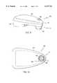
- one aspect of the present inventionincorporates the color sensor into a hand-held “mouse” device.
- the mouse deviceincludes an area on its top surface for seating an index finger of the human hand.
- a pressure-activated switchPositioned within this area is a pressure-activated switch that is operatively coupled to the circuitry for performing the colorimetric and reflectance readings.
- the sensoris mounted into the mouse device such that the focal aperture of the downward pointing reflector cone is in axial alignment with the pressure-activated switch. Accordingly, a user will be able to use the mouse to "point" with his or her index finger to an area of the sample surface, and will then simply press the switch using the same index finger.
- color sensor of the present inventioninclude high-speed color-inspection/control in a manufacturing or production environment, analogous to the uses described in U.S. Pat. No. 5,021,645 to Satula et al.; or color matching of cosmetics or clothing accessories to a skin-color or foundation make-up color of a customer, analogous to the uses described in U.S. Pat. No. 5,537,211 to Dial.
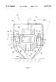
- FIG. 1is a cross-sectional, elevational view of an embodiment of the color sensor of the present invention
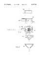
- FIG. 2is a top view of the annular collar component of the color sensor
- FIG. 3is a side view of the annular collar component of the color sensor
- FIG. 4is a top view of the color sensor of an embodiment of the present invention as incorporated into a circuit board;
- FIG. 5is a cross-sectional, elevational view of the embodiment of FIG. 4;
- FIG. 6is a cross-sectional, elevational, and exploded view of an embodiment of the color sensor and circuit board of the present invention.
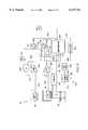
- FIG. 7is a schematic block diagram representation of circuitry for use with the present invention.
- FIG. 8is a schematic block diagram representation of alternate circuitry for use with the present invention.
- FIG. 9is a perspective view of a hand-held "mouse” device incorporating the present invention.
- FIG. 10is a top view of the hand-held "mouse" device of FIG. 9;
- FIG. 11is a cross-sectional, elevational view of the hand-held "mouse” device incorporating the present invention.
- FIGS. 12a-crespectively show a top view, one cross-sectional elevational view, and another cross-sectional elevational view of an alternate embodiment of the annular collar component of the present invention
- FIG. 13is a cross-sectional, elevational view of an alternate embodiment of the color sensor of the present invention.
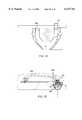
- FIG. 14is a cross-sectional, elevational view of another alternate embodiment of the present invention.
- FIG. 15is a cross-sectional, elevational view of another alternate embodiment of the present invention.
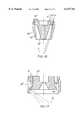
- FIG. 16is a cross-sectional, elevational view of another alternate embodiment of the collar and reflector cone components of the present invention.
- FIG. 17is a cross-sectional, elevational view of another alternate embodiment of the collar and reflector cone components of the present invention.
- the color sensor 10 for sampling the color of a sample surface 12comprises a printed circuit board 13; a plurality of light sources, such as light emitting diodes (LEDs) 18 mounted in apertures 19 extending through the circuit board 13, each of the LEDs emitting light of a substantially different wavelength band spaced in the visible spectrum; a reference photodetector 20 mounted to the top surface 14 of the printed circuit board; a sample photodetector 22 mounted to the bottom surface 15 of the printed circuit board, substantially back-to-back with the reference photodetector 20; an annular collar 24 mounted to the bottom surface 15 of the printed circuit board; an optical cap 26 mounted to the top surface 14 of the printed circuit board; and a reflector cone 28 mounted onto the collar 24.
- LEDslight emitting diodes
- the collar 24is an annular component having a plurality of emitter apertures 30 bored through the collar in an axial direction, and circumferentially spaced around a receiver aperture 32 that is axially bored through a frustoconical receptor piece 36.
- the receptor piece 36extends and points downward from the bottom surface 38 of the collar 24 along axis A.
- a rectangular cavity 40 for housing the sample photodetector 22extends into the collar 24 from the top surface 42 of the collar, substantially at axis A, and is in direct optical communication with the receiver aperture 32, such that light waves reflected into the receiver aperture 32 of the receptor piece 36 can contact the sample photodetector 22.
- the same cavity 40 for housing the sample photodetector 22can also be used to mount an optional optical filter 41 constructed of flat glass or plastic.
- a filter 41mounted at the bottom of the cavity 40, at the opening of the receiver aperture 32, and aligned with axis A, could serve the purpose of excluding any unwanted light, e.g., infrared light in the case of a sensor optimized for the visible spectrum.
- the filter 41could be an infrared filter or any other band-pass filter as necessitated by the envisioned use of the sensor 10.
- the filter 41will also protect the face of the sample photodetector. It is also within the scope of the invention to provide a similar optical filter over the reference photodetector 20 to band-pass filter the light reflected thereto.
- the plurality of LEDs 18are preferably mounted into apertures 19 of the printed circuit board 13 such that a light emitting portion of each LED extends into a corresponding one of the emitter apertures 30.
- the optical capis mounted to the printed circuit board 13 such that the cap forms an enclosed cavity 44 over the entire array of LEDs 18.
- Each of the plurality of LEDsare also mounted on the printed circuit board 13 such that a portion of the light emitted by the LED is emitted or reflected backwards (upwardly) into the cavity 44 formed by the optical cap 26.
- the reference photodetector 20is centrally mounted with respect to the array of LEDs 18 to the top surface 14 of the printed circuit board, within the cavity 44.
- the inner surface 46 of the optical capis preferably coated with an opaque, substantially non-absorbing, integrating coating such as a flat white paint. Therefore, light waves emitted from the LEDs through the top surface 14 of the printed circuit board, and into the cavity 44, are transmitted to the integrating surface 46 and are directly or indirectly reflected from the integrating surface to the reference photodetector 20.
- the reflector cone 28is attached to the bottom 38 of the collar and has an aperture 48 through the tip 50 of the reflector cone.
- the aperture 48is in axial alignment with the axis A of the collar 24, and in turn, is in alignment with the receiver aperture 32 of the collar.
- the reflector cone 28has a substantially frustoconical inner surface which forms a cavity 53 between the collar 24 and the reflector cone 28.
- the reflector cone 28also has an conical reflector surface 52, preferably coated with a chrome plating (or any other suitable reflective coating), in alignment with each of the axes B of the emitter apertures 30, and which is angled, with respect to the axes B, inwardly towards the axis A, at an angle that is approximately 22.5°.
- the light emitted through the emitter apertures 30 and reflected from the conical reflective surface 52will contact the aperture 48 of the reflector cone, and in turn the sample surface 12, substantially at an angle of 45° with respect to the flat tip 50 of the reflector cone (or with respect to the sample surface 12, if applied to a sample).
- the diffuse component of the reflected light waveswill be transmitted upwardly from the sample along axis A, through the receiver aperture 32 to the sample photodetector 22.
- the reference photodetector 20when one of the LEDs is activated, and when the flat tip 50 of the reflector cone is abutting a sample surface 12, the reference photodetector 20 will sample light waves emitted from the portion of the LED 18 extending through the top surface 14 of the printed circuit board and reflected from the optical cap's inner surface 46, and the sample photodetector 22 will sample the diffuse component of the light waves emitted from the portion of the same LED 18 extending through the bottom surface 15 of the printed circuit board and reflected off the sample surface 12.
- the use of the 450° geometry of the present inventioncorresponds more closely with the visual viewing of samples and excludes the specular component of reflectance. The spectral reflectance of the color sample can thus be calculated for this particular LED (or combination of LEDs) from the readings of the reference photodetector 20 and the sample photodetector 22 using a dual beam method as is described in detail below.
- the operable range for the angle of the conical reflector surfaceis 20.5° to 24.5°, while the preferred range is 22.4° to 22.6°.
- the angle of the conical reflector surfacebe within the above ranges for the 45°/0° geometry.
- angle Acan be altered to obtain optical geometries that are better suited for particular uses. For example, when using the present invention to detect characteristics of a patient's skin (such as skin color), a 20°/0° geometry as shown in FIG. 16 or modified-diffuse/0° geometry as shown in FIG. 17 may be preferred. These alternate embodiments are better suited for remote color sensing of a sample surface and will be discussed in greater detail below.
- each emitter aperture 30is preferably formed with an upper cylindrical channel 54 and a lower cylindrical channel 56.
- the lower cylindrical channelis concentrically aligned with the upper cylindrical channel 54 along the axis B of the emitter aperture and has a smaller diameter than the upper cylindrical channel 54.
- the lower cylindrical channelthus acts to collimate the light waves emitted through the emitter aperture 30, to the conical reflective surface 52, and onto the sample surface 12.
- the emitter apertures 30can vary in size to allow for maximum flexibility in LED selection.
- the LEDs 18'can be mounted to a separate daughterboard 162 that, in turn, is mounted to the top surface 14' of the main circuit board 13' via mating connectors 164, 166.
- the main circuit board 13'will contain the electronics (described below) that drive the LEDs 18', and the electronic signals for driving the LEDs, produced by the main circuit board 13', will be passed to the daughterboard through the mating connectors 164, 166.
- the LEDs 18'will extend into the apertures 19' extending through the main circuit board 13'.
- An optical cap 26' designed to be fitted over the daughterboard 162will be mounted to the top surface 14' of the main circuit board 13' and will act to reflect light emitted from the LEDs 18' to the reference photodetector 20 as described above.
- the collar 24 and reflector cone 28will be mounted to the bottom surface 15' of the main circuit board 13' and will act to direct light emitted from the LEDs 18' to the sample surface at approximately 45°, and to direct the diffuse component of the light reflected from the sample to the sample photodetector 22 as described above.
- the light sourcescan be mounted or positioned in other ways; so long as a portion of the light emitted from the light source is transmitted or reflected through the emitter aperture 30 and another portion of the light emitted from the light source is emitted or reflected into the cavity 44 within the optical cap 26.
- mount each LEDto the bottom surface 15 of the printed circuit board, extending completely within the emitter aperture 30, and to bore a hole through the printed circuit board 13 above the LED 18 such that the light emitted from the LED 18 will be transmitted through the hole and into the cavity 44 and will also be transmitted through the lower cylindrical channel 56 and into the cavity 53 as described above.
- the LEDscan be clustered at any light-shielded point of circuit board; and when activated, an acrylic "light-pipe" 180 can be used similar to a fiber optic element, to direct a first fraction 182 of light waves to the sample surface 12 so that it is incident at 45°.
- the sample photodetector 22will be in position to detect the diffuse component of the light reflected from the sample surface. Because the light-pipe 180 tends to bleed light waves radially therefrom, the reference photodetector 20 can be in any shielded position to receive a fraction 184 of light bleeding from the light-pipe 180.
- photodetectors for use with present inventioncan include photoconductive cells, photodiodes, photoresistors, photoswitches, phototransistors, phototubes, photovoltaic cells, light-to-frequency converters, or any other type of photosensor capable of converting light into an electrical signal.
- Such photodetectorscan include integrated conversion of light to voltage with electronic amplification components; integrated conversion of light to digital frequency components; or integrated analog to digital conversion components.
- the color sensor 10is preferably mounted to the distal or pointed end 59 of a pointed printed circuit board 13.
- the circuitry for controlling the LEDs and photodetectors, and for transferring the measured signals to a host computerare also mounted to the printed circuit board 13.
- the reference photodetector 20 and the sample photodetector 22are shown in FIG. 5 as off-the-shelf chip devices mounted to the printed circuit board 13 via pins 60.
- the LEDsare also off-the-shelf devices mounted to the printed circuit board 13 via leads 61.
- Suitable photodetectors for use with the present inventionare OPT209PJ from Burr-Brown or TSL230A from Texas Instruments; and suitable LEDs for use with the present invention are NLPB-300A from Nichia, NSPB-300A from Nichia, NSPG-300A from Nichia, E166 from Gilway, E104 from Gilway, E198 from Gilway, E102 from Gilway, E472 from Gilway, BL-B4331 E from America Bright, or HLMP-K640 from Hewlett Packard.
- the LEDsare encapsulated so as to provide a lens integral with the LED.
- a non-encapsulated light sourcecan be utilized by incorporating a lens within the emitter aperture 30.
- a shell 62consisting of an upper shell piece 64 and a lower shell piece 66 is mounted around the printed circuit board 13 and color sensor 10 and is ergonomically shaped for gripping and manipulation by an operator's hand.
- the shellcontains a pressure-activated switch 68 that is operatively coupled to the circuitry contained on the printed circuit board, such that the operator will be able to initiate a color measurement process by activating the switch.
- the optical cap 26is an integral part of the upper shell piece 64 and the collar 24 is an integral part of the lower shell piece 66.
- the reflector cone 28is preferably an independent piece which is mounted to the shell 62 after mounting the upper shell piece 64 and lower shell piece 66 to the printed circuit board 13.
- the separate sensor parts, the upper shell piece 64, the lower shell piece 66 and the reflector cone 28are all preferably made from an opaque black ABS plastic.
- upper shell piece 64has an area 168 for seating an index finger 170 of a human hand.
- the switch 68Positioned in this area 168 is the switch 68, operatively coupled to the circuitry of the sensor such that pressure activation of the switch will activate the circuitry, and will thus initiate a calorimetric reading of the sample surface 12.
- the switch 68is in axial alignment with the aperture 48 and with axis A of the collar 24, and in turn, is in alignment with the receiver aperture 32 of the collar.
- the userwill be able to use the present invention to "point" with his or her index finger 170 to an area of the sample surface 12 that he or she wishes to take a calorimetric reading of the sample surface, and will then simply press the switch 68 using the same index finger.
- the measured signals received by the sensor 10 and preprocessed by the circuitry 13are transmitted back to a host computer through a serial interface modular connector 58.
- the serial interface connector 58can be made to support the RS-232 protocol, or can be configured to support the Apple Desktop Bus (ADB) protocol.
- ADBApple Desktop Bus
- the serial interface connector 58also supplies power to the sensor circuitry, as provided by the host computer.
- the reference photodetector and the sample photodetector 20,22are preferably identical devices and are preferably mounted back to back on the printed circuit board so that, not only will the photodetectors be substantially identical, they will share environmental characteristics, such as temperature, humidity, electrical noise, etc. Therefore, the photodetectors 20,22 will be substantially thermally matched so that temperature stabilization of the photodetectors is not required. This is because the temperature variances will cancel each other out in the reflectance calculation as described below.
- the collar 24also provides thermal isolation between the LEDs 18 and the sample photodetector 22, thus preventing heat generated by the LEDs from interfering with the thermal matching between the reference and sample photodetectors. Furthermore, no gratings or filters are required because the use of LEDs of different wavelengths eliminates the need for such gratings or filters.
- each pin 60' of the reference photodetector 20is optionally coupled to a corresponding pin 60' of the sample photodetector by a thermally conductive material 167.
- This material 167enhances the matching of thermal characteristics between the reference photodetector 20 and the sample photodetector 22. If the corresponding pins 60', 60" are coupled to the same circuit connection, i.e., Vcc or ground, the material 167 may also be electrically conductive so as to facilitate the matching of electrical characteristics.
- the senor 10need not be designed as mounted to a printed circuit board.
- a mounting plate or basecan be provided in place of the printed circuit board; or the collar 24 or another component can be designed to house the LEDs and photodetectors within the sensor 10 in the arrangement required by the present invention.
- circuitry for controlling the sensor 10 and preprocessing the measured signals taken from the sensorcomprises a microcontroller 80, an analog to digital converter 82, a series of LED switches 84, and a programmable LED power source 86.
- the microcontroller 80is operatively coupled to the switch 68.
- the microcontrollercommunicates with the serial interface modular connector 58 through a serial communications bus 88.
- the microcontroller 80can control which of the LEDs 18 are activated through an LED select line 90 and can control the intensity of the activated LEDs through an LED level line 92 sent to the programmable LED power source 86.
- the programmable LED power sourceprovides the LED power through an LED power line 96, and also includes an LED current sense input line 94 from a current detector housed within the sensor 10 as feedback to the programmable LED power source calculation.
- the LED current control circuitis not critical to the operation of the device, but can be used to optimize LED signal to desired levels.
- a sample channel output line 97is coupled between a multiplexer device 98 and the sample photodetector 22 housed within the sensor 10, and a reference channel output line 99 is coupled between the multiplexer device 98 and the reference photodetector 20 housed within the sensor 10.
- the microcontroller 80is able to control which of the sample outlet channel line 97 or the reference channel output line 99 is sent to the analog to digital converter device 82 through a multiplexer control line 100, and the microcontroller 80 controls the operations of the analog to digital converter 82 through an A/D control line 102.
- the digitized measurement from the sample photodetector 22 or the reference photodetector 20 output by the analog to digital converter 82is sent back to the microcontroller 80 via a digitized value line 104.
- the LED current sense line 94can also be used to further correct the reference channel response for each individual LED against some expected response.
- the color sensor 10is operated as follows. To obtain reflectance readings of a sample surface, the reflector cone aperture 48 is first placed on the sample surface 12 and the switch 68 is activated. Upon activation of the switch 68, the microcontroller will take the digitized "dark" readings of the sample output channel 97 (Is d ) and of the reference output channel 99 (Ir d ) through the analog to digital converter device 82 (note that none of the LEDs 18 are activated). Next, the LED switches 84 are activated in sequence by the microcontroller 80, thus activating the LEDs 18 of the respective wavelengths in sequence.
- the microcontrollertakes the digitized readings of the sample output channel 97 (Is.sub. ⁇ ) and of the reference output channel 99 (Ir.sub. ⁇ ), where " ⁇ " represents the peak wavelength of the particular LED activated.
- the raw, unscaled device reflectance Ru.sub. ⁇ for each given LED of peak wavelength Ais then calculated using the following equation: ##EQU1##
- the microcontroller 80measures Is d and Ir d right after each other, but just before the Is.sub. ⁇ and Ir.sub. ⁇ measurements are made. This is an attempt to reduce the effect of photodetector offset drifts, which can be seen by the dark measurement. Similarly, Is.sub. ⁇ and Ir.sub. ⁇ are measured right after each other for a given LED, which is obviously an attempt to reduce photodetector gain drifts.
- Nis the number of LEDs illuminated during the cycle.
- ⁇ icorresponds to measurements made for the ith LED in the measurement cycle.
- the color sensorshould first be used to "calibrate” the photodetectors by activating the color sensor 10 over a black or non-reflecting calibration surface to obtain a "black” reflectance reading R black , and then activating the color sensor 10 over a reflecting diffuse white surface to obtain a "white” reflectance reading R white .
- the reflector cone aperture 48is first placed on the "black” non-reflecting calibration surface, the switch 68 is pressed, and reflectance readings are made of the non-reflecting calibration surface. Then, the reflector cone aperture 48 is placed on the "white” reflecting calibration surface, the switch 68 is pressed, and reflectance readings are made of the reflecting calibration surface.
- R.sub. ⁇is the normalized and bias corrected reflectance measurement for a given LED of peak wavelength ⁇
- S wis a "white” scaling factor obtained from a standard reference device, such as a Gretag SPM100 laboratory grade spectrophotometer
- S bis a "black” scaling factor obtained from a standard reference device.
- R'is a vector of size N representing the normalized and bias corrected reflectance color value of the sample just measured
- Ru'is a vector of size N representing the raw, unscaled device reflectances of the sample just measured
- R' blackis a vector of size N representing the raw, unsealed device reflectances of a pre-measured "black” calibration tile
- R' whiteis a vector of size N representing the raw, unscaled device reflectances of a pre-measured white calibration tile.
- a combination of LEDscan be illuminated to provide the combined wavelengths for an entire RGB color wavelength band; thus requiring only three samples to be taken and calculated--i.e., one for all LEDs making up the RED band, one for all LEDS making up the GREEN band, and one for all LEDs making up the BLUE band.
- multiple LEDs of the same wavelengthmay be activated simultaneously to increase the apparent brightness associated with a particular wavelength band.
- a light-to-frequency converter devicesuch as a TSL230 from Texas Instruments, as a photodetector.
- the light-to-frequency converter deviceemits a frequency signal that corresponds to the brightness of the light detected by the device. Accordingly, use of a light-to-frequency converter device may eliminate the need for analog-to-digital converter devices in the present invention, because the host computer or microcontroller will be able to calculate the reflectance based upon the frequency of the signal transmitted by the light-to-frequency device.
- An on-board programmable memorymay optionally be included in the circuitry to contain hardware setup and calibration information; and accommodation of a liquid crystal display may also be included to provide a user read-out.
- Other enhancementscan include an internal battery for wireless operation.
- the present embodiment for colorimetric operationutilizes ten LEDs of different wavelengths.
- the peak wavelengths of the ten LEDs utilizedare 430, 450, 470, 525, 558, 565, 585, 594, 610, and 635 nanometers respectively. It is noted that although the peak wavelengths are indicated, each LED transmits wavelengths of a particular bandwidth, which typically ranges from ten to one-hundred nanometers wide.
- LEDsmay be utilized in the present invention, depending upon the accuracy and repeatability requirements of the sensor. For example, a sensor utilizing three or six LEDs will have lesser accuracy or repeatability than in the ten LED embodiment and a sensor utilizing sixteen LEDs will have greater accuracy and repeatability than the ten LED embodiment.
- the peak wavelengths of the three LEDsare 450, 555, and 610 nanometers respectively; if a six LED embodiment is utilized, the peak wavelengths of the six LEDs are 450, 470, 512, 555, 580, and 610 nanometers respectively; and if a sixteen LED embodiment is utilized, the peak wavelengths of the sixteen LEDs are 430, 450, 470, 489, 512, 525, 558, 565, 574, 585, 594, 605, 610, 620, 635, and 660 nanometers respectively.
- this ratio vector R'is then converted into a usable color measurement value t (for example, the color measurement value t can be the CIE XYZ tristimulus value for the sample) through a linear or a non-linear operation.
- a mathematical profile of the sensor 10, which obtained the measurementmust first be determined. This is because the conversion from the reflectance ratio vector R' to the color measurement value t depends upon the unique spectral characteristics of the sensor components used to obtain the reflectance ratio vector R'.
- the mathematical profile of the sensor 10is based upon the following matrix/vector equation:
- R'is an M ⁇ 1 vector of the recorded reflectance ratios
- S Tis an M ⁇ N matrix representing the spectral power distributions of the M spectrally unique LEDs 18
- Dis an N ⁇ N diagonal matrix representing the spectral sensitivity of the sample photodetector
- bis an M ⁇ 1 bias vector
- ris an N ⁇ 1 vector representing the actual spectral reflectance of the sample.
- the mathematical profile of the deviceis determined by finding S T , D, and b. These values are found by taking measurements of samples having known spectral reflectances r, using the sensor 10. In simple terms, the determination of the mathematical sensor profile is based on the spectral sensitivity of the sample photodetector, the spectral power distributions of the LEDs 18, and the reflectance of several known samples.
- the spectral sensitivity D of the sample photodetectoris available from the photodetector's manufacturer. Provided a quality photodetector is used, the sensitivity should be the same, within an acceptable range, over all detectors.
- LED manufacturersare not able to ensure the exact spectral shape and peak wavelength across a particular batch of LEDs. For this reason, it is necessary to measure the spectral power distribution ST of each LED with a spectraradiometer. But because, the spectraradiometer provides only the relative shape of the distribution, the absolute power of the LEDs and the bias vector b are determined by performing a measurement with the sensor 10 on each of two spectrally known samples having known reflectances r 1 and r 2 . Typically, black and white samples are used. These measurements provide M sets of 2 equations to solve for the two unknowns (S T and b), where we already have each row of S T to within a constant:
- Equ. 8the determination or approximation of t according to Equ. 8 will be apparent to one of ordinary skill in the art.
- E ⁇is the expectation operation over the system noise and reflectance spectra of interest
- Fis a function which transforms from the color space containing t to a perceptually uniform color space (i.e., accounts for the sensitivity of the human visual system)
- Gis the function approximating t(G(c) ⁇ t). Accordingly, G is the function to be found. Depending upon the application, it may be desirable to select G as either a linear or non-linear function.
- the function Fwill be of a form which makes an analytical solution to the above optimization problem difficult.
- the transformation Gcan be found by a two step process. In the first step, an initial estimate for G is obtained analytically which minimizes the error in the CIE XYZ space (i.e., the function F is ignored). This solution is easily computed using simple matrix algebra. In the second step, this estimate is used as a starting point for a numerical optimization algorithm which minimizes the above non-linear problem. Any standard non-linear optimization algorithm will be sufficient for this task.
- the expectation operator in the above optimization problemis taken over a set (or ensemble) of reflectance spectra.
- the above approachrequires some representative reflectance samples which the sensor may be used to measure. From these samples, a reflectance correlation matrix is constructed and used in the first analytical step (when the function F is ignored).
- the analytical solutionis given by:
- K r E ⁇ rr T ⁇is the reflectance correlation matrix which is, estimated by: ##EQU3## where R is some ensemble of N R reflectance spectra. The numerical step is then performed over each sample in R.
- the conditioning of the transformation matrixcan be set as an optimization constraint. The amount of conditioning or regularization should be a function of the system noise thereby producing a transformation which gives good repeatability.
- the function Fcan be locally linearized for each sample in the ensemble R. This linearization provides a means to obtain analytically a solution which may be perceptually acceptable, and allow the incorporation of the system noise for good repeatability.
- the pseudo-inverse operationmay also be needed in the colorimetric case.
- the pseudo-inversecan be computed by dropping numerically insignificant singular values in the matrix S T K r S.
- the present inventionby installing a photodetector 160 in place of an LED, can also be used as a gloss meter.
- the photodetector 160would have to replace a first LED which is positioned 180° away from a second LED 18" with respect to axis A. The photodetector would thus be able to detect the specular component of the light waves transmitted from the second LED and reflected off the sample.
- LEDs 18 having wavelengths in the non-visible spectrumcan be utilized for various purposes. For example, utilizing LEDs in the infrared spectrum will allow the sensor to measure the infrared reflectivity of a sample surface. In a related application, the infrared LEDs can also be used to transmit data to a host computer through the reflector cone's aperture 48; thus eliminating the need for the serial interface connector 58.
- the present inventioncan also be used to measure the radiance of a given sample that is self luminous, i.e., a CRT display screen. This application does not need to utilize the LEDs.
- an alternate circuit for the present inventionutilizes a successive approximation technique to perform measurement of spectral reflectances from the dual beam sensor 10.
- the circuitry for performing the successive approximation measurementcomprises a microcontroller 100, a digital to analog converter 102, a D latch. 104, another D latch 106, a sample channel voltage comparator device 108, a reference channel voltage comparator device 110, and an OR gate 112.
- the microcontrolleris operatively coupled to the switch 68.
- the microcontroller 100communicates with the serial interface modular connector 58 through a communications bus 114.
- the microcontrollercan control which of the LEDs 18 are activated through an LED select line 116, which indicates which of the LED switches 118 are to be activated or inactivated.
- the approximation circuitalso utilizes a voltage reference 120, which is a fixed stable voltage reference used by the digital to analog converter 102 and the reference channel voltage comparator device 110.
- the approximation circuitalso utilizes an LED variable control device 122, which provides variable resistance used to gate the amount of current allowed to flow from the LED's current drain. This device is fed by an LED gate signal 124 sent from a delay ramp circuit 126 that generates a voltage ramp beginning at a low voltage level, and over time, becomes higher in a linear fashion.
- the approximation circuitis initialized as follows: Initially, upon activated by the switch 68, the microcontroller activates a clear line 128 which clears both D latches 104,106; the microcontroller transmits to the digital to analog converter 102 a 0.5 full scale code through a D/A control line 130; and the internal LED select variable i (which indicates the particular LED switch to be activated) is initialized to zero (no LED selected).
- the reflectivity measurement process for a given LED iis conducted as follows: The microcontroller 100 will first select LED i through the LED select line 116 sent to the LED switches 118. LED power 132 is applied to the LED i, but the LED i does not yet activate because the LED variable control device 122 is "off.” Next, the microcontroller 100 activates a "start” line 134, which is coupled to the clock input 136 of the D latch 106. Accordingly, the Q output 138 of the D latch 106 ("LED on”) becomes activated as the "start” signal ripples through the D latch 106. This "LED on” signal 138 is sent to the delay ramp circuit 126, which in turn begins applying the linearly increasing "LED gate” signal 124 to the LED variable control device 122.
- the LED variable control device 122now. activated, allows current to flow from the LED power source 132 through the previously selected LED switch 118 through the corresponding LED 18 and LED cathode 140 and into an "LED current drain” 142.
- the LEDsince current is flowing through the LED 18, the LED now emits light at its predetermined wavelength; however, the brightness depends upon the linearly increasing "LED gate” signal 124.
- the reference photodetector 20receives light from the activated LED 18 and transmits a signal indicative of the measured light to the voltage comparator 108 over a reference channel output line 144.
- the sample photodetector 22receives light reflected from the color sample, as discussed above, and transmits a signal indicative of the detection of this light to the voltage comparator circuit 108 over a sample channel output line 146.
- intensity of light from the LED 18increases until either the sample output voltage comparator 108 or the reference output voltage comparator 110 is activated.
- the sample channel voltage comparator 106will be activated if the voltage on the sample channel output line 146 is greater than the analog output 152 from the digital to analog comparator 102, and the reference channel voltage comparator 104 will be activated if the reference channel output line 144 voltage is larger than the voltage reference 120.
- the sample output voltage comparator 108If the sample output voltage comparator 108 is activated, it activates the "X>Y" line 148, which is coupled to the clock input 149 of the D latch 104. Therefore, upon the "X>Y” 148 signal being activated by the sample channel voltage comparator, the D latch 104 will correspondingly notify the microcontroller 100 over the "X>Y (held)" line 154. At this time, the microcontroller 100 will determine if the granularity (resolution) of the D/A setting has been reached and, if so, this measurement is reported to the host computer through the RS232 serial link 58, and the measurement is complete.
- the microcontroller 100determines that the granularity of D/A setting has not been reached, the digital to analog signal is increased over the digital to analog control line 130, the microcontroller sets the "clear line” 128 clearing both D latches 104,106 and restarts the above measurement process beginning with activating the "start" line 134.
- the reference channel voltage comparator 110is activated, this indicates that the reference channel output 144 voltage is larger than the voltage reference 120. Activation of the reference channel comparator 108 thus causes the D latch 106 to be cleared. The microcontroller 100 will sense this, through a "fault" signal, and will decrease the D/A control signal 130 to the digital to analog converter 102, and will again proceed with the above measurement process starting by activating the "start line” 134.
- the above successive approximation circuitcan be used to measure the sample channel output 146 with respect to the reference channel output 144.
- This methoduses the digital to analog (D/A) converter 102 to set a threshold level 152 against which the sample channel output 146 is compared. If the threshold level is too low, it is increased; if it is too high, it is decreased.
- the threshold value being soughtis that which matches the sample channel output 146 at the closest possible instant to when the reference channel output 144 matches the stable voltage reference 120.
- This method of "hunting" for the appropriate thresholdis iterative, and when certain optimizations, such as a binary tree search algorithm, are employed, it can be relatively quick. When the final threshold is discerned, the digital representation corresponding to the sample channel is known.
- the stable voltage reference 120is both used to generate the output voltage 152 of the D/A 102, as well as in the comparison of the reference photodiode channel output 144, the act of comparing the sample photodiode channel output 146 to the D/A output voltage 152 is effectively the same as the direct comparison of the sample photodiode channel output 146 with the reference photodiode channel. Furthermore, since the output voltage 152 of the D/A 102 is defined by the following relationship:
- the act of finding the digital setting corresponding to the appropriate thresholdis the same as finding the value of sample channel divided by the reference channel.
- the above circuitis equally valid when a means to scale the sample and/or reference channels by known quantities is used.
- the binary tree search algorithmcan even be further improved by noting the time discrepancy between the triggering of the sample channel comparison and the triggering of the reference channel comparison, and scaling next resulting "expected" threshold setting accordingly.
- the reference channel output 144be used as the reference voltage by which the D/A output voltage 152 is generated; this is the most direct means of calculating the desired value of sample channel output divided by reference channel output.
- annular collar 24'has a plurality of emitter apertures 72 angled at a 45° angle towards the axis ⁇ , eliminating the need for the 22.5° conical reflective surface within a reflector cone, and eliminates the need for the reflector cone altogether. It is noted that the different sizes depicted for the emitter apertures 72 corresponds to different sizes of LEDs used.
- an alternate embodiment of the inventionincludes an optical lens 76 in place of the reflective surfaces of the reflector cone.
- the optical lensacts to bend the lightwaves emitted from the emitter apertures 30 to a 45° angle towards the axis A.
- a "low-end" color sensorthat does not utilize the reference photodetector 20, yet may utilize any or all of the novel elements described above for use with a hand-held, single-beam color sensor.
- an important element in such a single-beam color sensorwould be the LED current sense input line 94. It would also be beneficial in such an embodiment to inject the current sense signals into the sample photodetector 22 and an associated amplification circuit (whether internal or external to the sample photodetector) to provide advanced gain and offset correction.
- a reflector cone 28"includes a conical reflector surface 52" that is angled with respect to the axes B of the emitter apertures 30" at a 10° angle. Light emitted through the emitter apertures 30" and reflected from the conical reflective surface 52" will contact the sample surface 12 at an angle of 20°. Therefore the embodiment as shown in FIG. 16 will have a 20°/0° geometry. As shown in FIG. 16
- a collar 24'"includes a radially outwardly extending, and substantially conical reflective surface 190, which intersects axes B such that light emitted through the emitter apertures 30'" will be reflected towards a curved, inner reflective surface 192 of a reflector cone 28'".
- the light reflected from the inner reflective surface 192 towards the sample surface 12will thus be substantially diffuse. Therefore, the embodiment as shown in FIG. 17 will have a modified-diffuse/0° geometry.
Landscapes
- Physics & Mathematics (AREA)
- Spectroscopy & Molecular Physics (AREA)
- General Physics & Mathematics (AREA)
- Spectrometry And Color Measurement (AREA)
- Investigating Or Analysing Materials By Optical Means (AREA)
Abstract
Description
Measurement Cycle →Is.sub.d, Ir.sub.d, Is.sub.λ1, Ir.sub.λ1, Is.sub.λ2, Ir.sub.λ2 . . . Is.sub.λN, Ir.sub.λN
Measurement Cycle →Is.sub.d0, Ir.sub.d0, Is.sub.λ1, Ir.sub.λ1, Is.sub.λ2, Ir.sub.λ2 . . . Is.sub.λN, Ir.sub.λN, Is.sub.d1, Ir.sub.d1
Is.sub.dλ =((N Is.sub.d0 +Is.sub.d1)+(i-1)(Is.sub.d1 -Is.sub.d0))/(N+1) (Equ. 2)
Ir.sub.dλ =((N Ir.sub.d0 +Ir.sub.d1)+(i-1)(Ir.sub.d1 -Ir.sub.d0))/(N+1) (Equ. 3)
R.sub.λ =(Ru.sub.λ -R.sub.black)/(R.sub.white -R.sub.black))×(S.sub.w -S.sub.b)+S.sub.b (Equ. 4)
R'=((Ru'-R'.sub.black)/(R'.sub.white -R'.sub.black))×(S.sub.w -S.sub.b)+S.sub.b (Equ. 5)
R'=S.sup.T Dr+b (Equ. 6)
R.sub.1 '=S.sup.T Dr.sub.1 +b (Equ. 7a)
R.sub.2 '=S.sup.T Dr.sub.2 +b (Equ. 7b)
t=A.sup.T Lr (Equ. 8)
G=A.sup.T K.sub.r S[S.sup.T K.sub.r S].sup.-1 (Equ. 10)
G=K.sub.r S[S.sup.T K.sub.r S].sup.-1 (Equ. 13)
D/A output=voltage reference×(digital setting/full scale digital value)
(sample chan./ref. chan.)=(digital setting/full scale digital value)
Claims (27)
Priority Applications (1)
| Application Number | Priority Date | Filing Date | Title |
|---|---|---|---|
| US09/059,889US6147761A (en) | 1996-09-12 | 1998-04-14 | Color sensor |
Applications Claiming Priority (3)
| Application Number | Priority Date | Filing Date | Title |
|---|---|---|---|
| US2591196P | 1996-09-12 | 1996-09-12 | |
| US08/923,705US5963333A (en) | 1996-09-12 | 1997-09-04 | Color sensor |
| US09/059,889US6147761A (en) | 1996-09-12 | 1998-04-14 | Color sensor |
Related Parent Applications (1)
| Application Number | Title | Priority Date | Filing Date |
|---|---|---|---|
| US08/923,705DivisionUS5963333A (en) | 1996-09-12 | 1997-09-04 | Color sensor |
Publications (1)
| Publication Number | Publication Date |
|---|---|
| US6147761Atrue US6147761A (en) | 2000-11-14 |
Family
ID=21828725
Family Applications (3)
| Application Number | Title | Priority Date | Filing Date |
|---|---|---|---|
| US08/923,705Expired - LifetimeUS5963333A (en) | 1996-09-12 | 1997-09-04 | Color sensor |
| US09/059,889Expired - LifetimeUS6147761A (en) | 1996-09-12 | 1998-04-14 | Color sensor |
| US09/059,955Expired - LifetimeUS6020583A (en) | 1996-09-12 | 1998-04-14 | Color sensor |
Family Applications Before (1)
| Application Number | Title | Priority Date | Filing Date |
|---|---|---|---|
| US08/923,705Expired - LifetimeUS5963333A (en) | 1996-09-12 | 1997-09-04 | Color sensor |
Family Applications After (1)
| Application Number | Title | Priority Date | Filing Date |
|---|---|---|---|
| US09/059,955Expired - LifetimeUS6020583A (en) | 1996-09-12 | 1998-04-14 | Color sensor |
Country Status (6)
| Country | Link |
|---|---|
| US (3) | US5963333A (en) |
| EP (1) | EP0958488A4 (en) |
| JP (1) | JP2000512021A (en) |
| AU (1) | AU4339897A (en) |
| CA (1) | CA2265534C (en) |
| WO (1) | WO1998011410A1 (en) |
Cited By (60)
| Publication number | Priority date | Publication date | Assignee | Title |
|---|---|---|---|---|
| US6262804B1 (en) | 2000-02-04 | 2001-07-17 | X-Rite, Incorporated | Handheld color measurement instrument |
| US6345191B1 (en)* | 1999-03-29 | 2002-02-05 | F. Hoffman-La Roche Ag | System for quantitative determination of the local distribution of a quantity to be measured |
| US6381020B1 (en)* | 1998-04-15 | 2002-04-30 | Baldwin-Japan Ltd. | Optical system |
| US6384918B1 (en) | 1999-11-24 | 2002-05-07 | Xerox Corporation | Spectrophotometer for color printer color control with displacement insensitive optics |
| US6556300B2 (en) | 2001-05-22 | 2003-04-29 | Xerox Corporation | Color imager bar based spectrophotometer photodetector optical orientation |
| US6567170B2 (en) | 2001-06-25 | 2003-05-20 | Xerox Corporation | Simultaneous plural colors analysis spectrophotometer |
| US6567159B1 (en)* | 1999-10-13 | 2003-05-20 | Gaming Analysis, Inc. | System for recognizing a gaming chip and method of use |
| EP1314972A1 (en) | 2001-11-26 | 2003-05-28 | Gretag-Macbeth AG | Spectrophotometer and its use |
| US6584435B2 (en) | 2001-08-30 | 2003-06-24 | Xerox Corporation | Systems and methods for determining spectra using dynamic karhunen-loeve algorithms with measurements from led color sensor |
| US6587793B2 (en) | 2001-09-17 | 2003-07-01 | Xerox Corporation | Systems and methods for determining spectra using fuzzy inference algorithms with measurements from LED color sensor |
| WO2003058184A1 (en)* | 2002-01-11 | 2003-07-17 | Koninklijke Philips Electronics N.V. | Method of determining tristimulus values for rgb led illuminants |
| US6603551B2 (en) | 2001-05-22 | 2003-08-05 | Xerox Corporation | Color measurement of angularly color variant textiles |
| US6621576B2 (en) | 2001-05-22 | 2003-09-16 | Xerox Corporation | Color imager bar based spectrophotometer for color printer color control system |
| US6639669B2 (en) | 2001-09-10 | 2003-10-28 | Xerox Corporation | Diagnostics for color printer on-line spectrophotometer control system |
| US6721692B2 (en)* | 2001-08-30 | 2004-04-13 | Xerox Corporation | Systems and methods for determining spectra using dynamic least squares algorithms with measurements from LED color sensor |
| US6731421B2 (en) | 2001-04-23 | 2004-05-04 | Dee E. Willden | Wedge-shaped lensless laser focusing device |
| US6750442B2 (en) | 2002-03-06 | 2004-06-15 | Xerox Corporation | Use of spectral sensors for automatic media identification and improved scanner correction |
| US6825919B2 (en) | 2000-02-04 | 2004-11-30 | X-Rite, Incorporated | Handheld color measurement instrument |
| US20050047134A1 (en)* | 1997-08-26 | 2005-03-03 | Color Kinetics | Controlled lighting methods and apparatus |
| US20050052648A1 (en)* | 2003-07-23 | 2005-03-10 | Beat Frick | Spectral photometer and associated measuring head |
| US20050062970A1 (en)* | 2001-10-24 | 2005-03-24 | Jean-Pierre Delgrande | Dental colorimetry measuring apparatus |
| US20050062968A1 (en)* | 2003-09-23 | 2005-03-24 | Peterson Steven H. | Color measurement instrument |
| US20050068520A1 (en)* | 2001-02-02 | 2005-03-31 | Beimers Daniel J. | Handheld color measurement instrument |
| US20050160092A1 (en)* | 2004-01-16 | 2005-07-21 | Xerox Corporation | Reference database and method for determining spectra using measurements from an LED color sensor, and method of generating a reference database |
| US20050243318A1 (en)* | 2004-04-30 | 2005-11-03 | Baker Douglas V | Color measurement system |
| US20060000963A1 (en)* | 2004-06-30 | 2006-01-05 | Ng Kee Y | Light source calibration |
| US20060103864A1 (en)* | 2004-11-16 | 2006-05-18 | Datacolor Holding Ag | Method for designing a colorimeter having integral CIE color-matching filters |
| US20060119849A1 (en)* | 2004-11-17 | 2006-06-08 | Brian Levey | Tristimulus colorimeter having integral dye filters |
| US20060139644A1 (en)* | 2004-12-23 | 2006-06-29 | Kahn David A | Colorimetric device and colour determination process |
| US20060149151A1 (en)* | 2005-01-05 | 2006-07-06 | Aevora Beauty Concepts, Llc | Cosmetic color determinate system with infrared sensing |
| US20060152718A1 (en)* | 2005-01-13 | 2006-07-13 | Xerox Corporation | Systems and methods for selecting a reference database for determining a spectrum of an object based on fluorescence of the object |
| US20060203213A1 (en)* | 2003-11-14 | 2006-09-14 | Olympus Corporation | Mult-spectrum image capturing device and multi-spectrum illuminating device |
| US20060215162A1 (en)* | 2005-03-23 | 2006-09-28 | Colman Shannon | Reflectance sensor for integral illuminant-weighted CIE color matching filters |
| US20060244948A1 (en)* | 2005-04-12 | 2006-11-02 | Overbeck James L | Systems and methods for validating a security feature of an object |
| US20070035740A1 (en)* | 2005-08-15 | 2007-02-15 | Nisper Jon K | Optical instrument |
| US20070070351A1 (en)* | 2005-09-26 | 2007-03-29 | Fuji Xerox Co., Ltd. | Optical measuring device and image forming apparatus |
| US20070188764A1 (en)* | 2005-08-15 | 2007-08-16 | Nisper Jon K | Optical instrument and components thereof |
| US20070206391A1 (en)* | 2006-03-03 | 2007-09-06 | Fujitsu Limited | Light guide member, illumination apparatus, and image capturing apparatus using the same |
| US7301627B2 (en) | 2005-04-05 | 2007-11-27 | X-Rite, Inc. | Systems and methods for monitoring a process output with a highly abridged spectrophotometer |
| US20080174763A1 (en)* | 2006-12-21 | 2008-07-24 | X-Rite Europe Ag | Color Measuring head and Scanner Device Equipped Therewith |
| EP1983317A1 (en) | 2005-03-14 | 2008-10-22 | Datacolor Holding Ag | Spectrophotometer with light emitting diode illuminator |
| US7443508B1 (en) | 2005-05-18 | 2008-10-28 | Vie Group, Llc | Spectrophotometric scanner |
| US20090024276A1 (en)* | 2007-07-18 | 2009-01-22 | Gm Global Technology Operations, Inc. | System For Customizing Lighting and Sound Effects in a Vehicle |
| US20090099823A1 (en)* | 2007-10-16 | 2009-04-16 | Freeman David S | System and Method for Implementing Environmentally-Sensitive Simulations on a Data Processing System |
| US20090142082A1 (en)* | 2005-07-15 | 2009-06-04 | Hewllett-Packard Development Company, L.P. | Method of estimating a distance |
| WO2009155342A1 (en)* | 2008-06-19 | 2009-12-23 | Datacolor Holding Ag | Spectrophotometer system with modular 45/0 head |
| US20100208266A1 (en)* | 2009-02-17 | 2010-08-19 | Colman Shannon | Tristimulus colorimeter having integral dye filters |
| US20100259755A1 (en)* | 2007-12-20 | 2010-10-14 | Clark Stephan R | Color sensing device |
| US20110211196A1 (en)* | 2008-10-31 | 2011-09-01 | Dahlgren Brett E | Color measurement device |
| US20120188292A1 (en)* | 2011-01-12 | 2012-07-26 | Takahiro Inoue | Sensor device and electronic apparatus |
| US20120250022A1 (en)* | 2011-04-01 | 2012-10-04 | X-Rite Europe Gmbh | Hand-Held Color Measurement Device |
| US20130050068A1 (en)* | 2011-08-31 | 2013-02-28 | Takahiro Inoue | Sensor circuit and electronic apparatus |
| US20140301745A1 (en)* | 2013-04-05 | 2014-10-09 | Canon Kabushiki Kaisha | Image forming apparatus, image forming method, and medium |
| WO2015051408A1 (en)* | 2013-10-08 | 2015-04-16 | Paul Peng | System, method and apparatus for performing colour matching |
| US20160047685A1 (en)* | 2013-04-22 | 2016-02-18 | Sanofi-Aventis Deutschland Gmbh | Sensor Device for Attachment to a Drug Delivery Device |
| WO2017184664A1 (en)* | 2016-04-22 | 2017-10-26 | 3M Innovative Properties Company | Readers for process monitoring systems and methods of use |
| WO2018190698A1 (en)* | 2017-04-11 | 2018-10-18 | Any Canvas S.A.P.I. De C.V. | Device for dispensing hollow plastic spheres which detects the colour thereof, compiles personal information and is actuated remotely |
| CN110383025A (en)* | 2017-01-10 | 2019-10-25 | 康奈尔大学 | Sensors with elastomeric foams and uses thereof |
| JP2020080437A (en)* | 2020-03-04 | 2020-05-28 | キヤノン株式会社 | Optical sensor and image forming apparatus |
| US11044795B2 (en)* | 2017-01-19 | 2021-06-22 | Opple Lightin Co., Ltd. | Color picking device and color picking remote controller |
Families Citing this family (103)
| Publication number | Priority date | Publication date | Assignee | Title |
|---|---|---|---|---|
| DE10327392A1 (en)* | 2003-06-18 | 2005-01-13 | Sick Ag | Opto-electronic contrast sensor |
| US6459919B1 (en)* | 1997-08-26 | 2002-10-01 | Color Kinetics, Incorporated | Precision illumination methods and systems |
| DE19839676A1 (en)* | 1998-09-01 | 2000-03-02 | Heidelberger Druckmasch Ag | Setup and method for calibrating a monitor |
| US6157454A (en)* | 1998-09-02 | 2000-12-05 | Colorimeter, Llc | Miniature colorimeter |
| US6836325B2 (en) | 1999-07-16 | 2004-12-28 | Textron Systems Corporation | Optical probes and methods for spectral analysis |
| US6424416B1 (en)* | 1999-10-25 | 2002-07-23 | Textron Systems Corporation | Integrated optics probe for spectral analysis |
| US7483733B2 (en)* | 1999-07-26 | 2009-01-27 | Cardiosense, Ltd. | Non-invasive method and apparatus to detect and monitor early medical shock, and related conditions |
| WO2001006926A1 (en)* | 1999-07-26 | 2001-02-01 | Cardiosense Ltd. | An improved method and apparatus for the detection of medical conditions of shock and pre-shock |
| US6418805B1 (en) | 1999-11-18 | 2002-07-16 | Textron Systems Corporation | Constituent sensing system |
| US6369895B1 (en)* | 2000-02-16 | 2002-04-09 | Electronics For Imaging, Inc. | Color measurement instrument with asymmetric tapered sample area optical enclosure |
| AR031557A1 (en) | 2000-03-10 | 2003-09-24 | Textron Systems Corp | OPTICAL PROBE AND METHODS FOR SPECTRAL ANALYSIS. |
| FR2817616A1 (en)* | 2000-12-05 | 2002-06-07 | David Rosati | Device for testing filtration quality color by color from the ultraviolet to the infrared of e.g. sunglasses by use of quasi- monochromatic light sources and a polychromatic light source so that separate filters are not needed |
| FR2822267B1 (en) | 2001-03-16 | 2004-07-02 | Oreal | DEVICE FOR PROVIDING PERSONALIZED HAIR COLORING ADVICE |
| GB0107551D0 (en) | 2001-03-27 | 2001-05-16 | Matra Bae Dynamics Uk Ltd | Radiation monitor |
| AU148069S (en) | 2001-04-27 | 2002-06-04 | Procter & Gamble | Hair colour analyser |
| US6674530B2 (en)* | 2001-04-27 | 2004-01-06 | International Business Machines Corporation | Portable colorimeter |
| USD496871S1 (en) | 2001-04-27 | 2004-10-05 | The Procter & Gamble Company | Hair color analyzer |
| US6539323B2 (en) | 2001-05-04 | 2003-03-25 | Electronics For Imaging, Inc. | Methods and apparatus for correcting spectral color measurements |
| DE10122313A1 (en)* | 2001-05-08 | 2002-11-21 | Wolfgang P Weinhold | Method and device for the contactless examination of an object, in particular with regard to its surface shape |
| FR2826856B1 (en)* | 2001-07-09 | 2004-03-12 | Oreal | DEVICE FOR DETERMINING THE DEGREE OF A BODY TYPOLOGY CHARACTERISTIC |
| EP1278049A1 (en)* | 2001-07-18 | 2003-01-22 | CSEM Centre Suisse d'Electronique et de Microtechnique SA | Illumination module for a reflection spectrometer |
| US6659578B2 (en)* | 2001-10-02 | 2003-12-09 | Hewlett-Packard Development Company, L.P. | Tuning system for a compact optical sensor |
| US6655778B2 (en) | 2001-10-02 | 2003-12-02 | Hewlett-Packard Development Company, L.P. | Calibrating system for a compact optical sensor |
| US6764158B2 (en)* | 2001-10-02 | 2004-07-20 | Hewlett-Packard Development Company, L.P. | Compact optical sensing system |
| US20030111533A1 (en)* | 2001-12-19 | 2003-06-19 | Koninklijke Philips Electronics N.V. | RGB led based white light control system with quasi-uniform color metric |
| US20030230728A1 (en)* | 2002-06-13 | 2003-12-18 | Zhengshan Dai | Multiwavelength transilluminator for absorbance and fluorescence detection using light emitting diodes |
| AU2003209880A1 (en)* | 2003-03-05 | 2004-09-28 | Brytech Inc. | Colorimeter, colorimeter sensor unit and colour determination process |
| WO2005050148A2 (en)* | 2003-11-18 | 2005-06-02 | Octadem Technologies | Compact spectral readers for accurate color determination |
| US7251031B2 (en)* | 2004-01-23 | 2007-07-31 | Iguana Robotics, Inc. | Colorstick |
| EP1566617B1 (en)* | 2004-02-20 | 2015-11-11 | Carestream Health, Inc. | Apparatus and method for tooth shade measurement |
| EP1740914A2 (en)* | 2004-04-30 | 2007-01-10 | Ahura Corporation | Method and apparatus for conducting raman spectroscopy |
| DE602004019888D1 (en)* | 2004-06-18 | 2009-04-23 | St Microelectronics Res & Dev | Polarization-sensitive solid-state image sensor |
| GB2415776B (en)* | 2004-06-28 | 2009-01-28 | Carglass Luxembourg Sarl Zug | Investigation of vehicle glazing panels |
| EP1621857A3 (en)* | 2004-07-29 | 2006-04-12 | MHT Optic Research AG | Device for the determination of the colour value of transparent objects, in particular teeth |
| US7351245B2 (en)* | 2004-09-21 | 2008-04-01 | Bernice Joy Rozinsky | Apparatus and method for dislodging object from throat |
| US7265822B2 (en)* | 2004-10-01 | 2007-09-04 | Test Coach Corporation | Method and apparatus for determining presence of a component in a printed circuit board |
| US7679785B2 (en)* | 2004-10-28 | 2010-03-16 | X-Rite Europe Gmbh | Method for correcting measured image values |
| US7647083B2 (en) | 2005-03-01 | 2010-01-12 | Masimo Laboratories, Inc. | Multiple wavelength sensor equalization |
| EP1760453A1 (en)* | 2005-08-31 | 2007-03-07 | GretagMacbeth AG | Photelectric hand held system and optical system therefor |
| US7859668B2 (en) | 2005-12-15 | 2010-12-28 | Honeywell International Inc. | Apparatus and method for illuminator-independent color measurements |
| US8017927B2 (en) | 2005-12-16 | 2011-09-13 | Honeywell International Inc. | Apparatus, system, and method for print quality measurements using multiple adjustable sensors |
| US7573575B2 (en) | 2005-12-29 | 2009-08-11 | Honeywell International Inc. | System and method for color measurements or other spectral measurements of a material |
| US7688447B2 (en)* | 2005-12-29 | 2010-03-30 | Honeywell International Inc. | Color sensor |
| US7602493B2 (en)* | 2006-02-14 | 2009-10-13 | John Ramirez | Electronic color matching apparatus and method of display |
| US20070227447A1 (en)* | 2006-04-04 | 2007-10-04 | Honeywell International, Inc. | Control of a coating process |
| US8081304B2 (en) | 2006-07-31 | 2011-12-20 | Visualant, Inc. | Method, apparatus, and article to facilitate evaluation of objects using electromagnetic energy |
| US7996173B2 (en)* | 2006-07-31 | 2011-08-09 | Visualant, Inc. | Method, apparatus, and article to facilitate distributed evaluation of objects using electromagnetic energy |
| WO2008016590A2 (en) | 2006-07-31 | 2008-02-07 | Visualant, Inc. | System and method of evaluating an object using electromagnetic energy |
| US20080092947A1 (en)* | 2006-10-24 | 2008-04-24 | Applied Materials, Inc. | Pulse plating of a low stress film on a solar cell substrate |
| KR100875996B1 (en)* | 2006-12-05 | 2008-12-26 | 한국전자통신연구원 | Biochip Reader |
| WO2008069554A1 (en)* | 2006-12-05 | 2008-06-12 | Electronics And Telecommunications Research Institute | Biochip reader |
| DE102007002106B3 (en)* | 2007-01-09 | 2008-07-03 | Wolfgang Weinhold | Object's surface configuration examining device, has control and evaluation unit connected with light sources and light sensor, where light sources are arranged such that optical radiation axis runs in different reference planes |
| US20080305884A1 (en)* | 2007-06-06 | 2008-12-11 | Cameron Don T | Golf club grip |
| US20080305883A1 (en)* | 2007-06-06 | 2008-12-11 | Cameron Don T | Golf club grip |
| GB0712610D0 (en)* | 2007-06-29 | 2007-08-08 | Dalke Hilary | A Device for contrast assessment |
| DE102007037652A1 (en)* | 2007-08-09 | 2009-02-19 | OCé PRINTING SYSTEMS GMBH | Device and method for the metrological detection of a color of an object |
| US7592608B2 (en)* | 2008-01-22 | 2009-09-22 | Honeywell International Inc. | Apparatus and method for measuring and/or controlling ultraviolet-activated materials in a paper-making process |
| US8049892B2 (en)* | 2008-01-22 | 2011-11-01 | Honeywell International Inc. | Apparatus and method for camera-based color measurements |
| WO2009143488A1 (en)* | 2008-05-22 | 2009-11-26 | Mattel Inc. | Play sets |
| US20100004518A1 (en) | 2008-07-03 | 2010-01-07 | Masimo Laboratories, Inc. | Heat sink for noninvasive medical sensor |
| US8515509B2 (en) | 2008-08-04 | 2013-08-20 | Cercacor Laboratories, Inc. | Multi-stream emitter for noninvasive measurement of blood constituents |
| JP5224178B2 (en)* | 2008-08-12 | 2013-07-03 | 株式会社松風 | Dental colorimeter |
| SE532397C2 (en)* | 2008-10-09 | 2010-01-12 | Microfluid Ab | Fluid Film Gauges |
| ATE528627T1 (en)* | 2009-06-24 | 2011-10-15 | X Rite Europe Gmbh | HAND-HELD LIGHT METER |
| DE102009052159A1 (en)* | 2009-08-05 | 2011-02-10 | Georg Fritzmeier Gmbh & Co. Kg | Measuring device for determining a vegetation index value (REIP) of plants |
| US8890815B2 (en)* | 2009-09-30 | 2014-11-18 | Apple Inc. | Incorporating chromatic sensors in computer mice |
| GB2474701B (en)* | 2009-10-26 | 2014-04-30 | Richard Frank Lawn | A handheld device for measuring the colour properties of objects |
| US9603559B2 (en) | 2009-12-24 | 2017-03-28 | Children's Medical Center Corporation | Capillary refill time diagnostic apparatus and methods |
| GB201008177D0 (en)* | 2010-05-17 | 2010-06-30 | Scan Coin Ab | Coin discriminators |
| US8401809B2 (en) | 2010-07-12 | 2013-03-19 | Honeywell International Inc. | System and method for adjusting an on-line appearance sensor system |
| US8888207B2 (en) | 2012-02-10 | 2014-11-18 | Visualant, Inc. | Systems, methods and articles related to machine-readable indicia and symbols |
| FR2987118A1 (en) | 2012-02-17 | 2013-08-23 | Franck Hennebelle | METHOD AND DEVICE FOR MEASURING THE COLOR OF AN OBJECT |
| US9316581B2 (en) | 2013-02-04 | 2016-04-19 | Visualant, Inc. | Method, apparatus, and article to facilitate evaluation of substances using electromagnetic energy |
| US9041920B2 (en) | 2013-02-21 | 2015-05-26 | Visualant, Inc. | Device for evaluation of fluids using electromagnetic energy |
| US9664610B2 (en) | 2013-03-12 | 2017-05-30 | Visualant, Inc. | Systems for fluid analysis using electromagnetic energy that is reflected a number of times through a fluid contained within a reflective chamber |
| RU2015149802A (en)* | 2013-04-22 | 2017-05-26 | Санофи-Авентис Дойчланд Гмбх | AUXILIARY DEVICE INTENDED FOR USE WITH INJECTION DEVICE, METHOD OF ITS OPERATION AND COMPUTER PROGRAM FOR MANAGING AUXILIARY DEVICE FOR PERFORMING METHOD |
| EP2988806B1 (en)* | 2013-04-22 | 2022-04-27 | Sanofi-Aventis Deutschland GmbH | Supplemental device for use with an injection device |
| US10799149B2 (en) | 2013-06-19 | 2020-10-13 | Zoll Medical Corporation | Analysis of skin coloration |
| FR3025809B1 (en)* | 2014-09-12 | 2016-09-30 | Herakles | METHOD FOR CONTROLLING A PIECE BY COLORIMETRY |
| EP3054273B8 (en)* | 2015-02-09 | 2019-09-11 | Instrument Systems Optische Messtechnik GmbH | Colorimetry system for display testing |
| US9891109B2 (en)* | 2015-02-17 | 2018-02-13 | Nix Sensor Ltd. | Portable colour sensor |
| ES2886112T3 (en)* | 2015-09-30 | 2021-12-16 | Color Grail Res | Procedure for determining the reflectance of an object and associated device |
| US10488261B2 (en)* | 2015-12-18 | 2019-11-26 | Nix Sensor Ltd. | Compact portable color sensor |
| US10302496B2 (en) | 2016-02-09 | 2019-05-28 | Nasa Solutions, Llc | Method and apparatus for determining presence and operation of a component in a printed circuit board |
| WO2017163319A1 (en)* | 2016-03-23 | 2017-09-28 | ゾンデックス株式会社 | Color measurement device |
| KR101793255B1 (en)* | 2016-04-26 | 2017-11-02 | 주식회사 맥스덴탈 | Multi function light curing device to combine tip selectively |
| CN109313378B (en)* | 2016-06-15 | 2021-09-28 | 富士通先端科技株式会社 | Image pickup apparatus |
| JP6240794B1 (en)* | 2017-01-16 | 2017-11-29 | 幸福の科学 | Carbon black measuring device, carbon black measuring program, and carbon black measuring method |
| US10836077B2 (en) | 2017-09-13 | 2020-11-17 | Scott Charles Andrews | Process and system for fabricating a colored powder coating composition from solid filaments |
| DE102018200162A1 (en)* | 2018-01-08 | 2019-07-11 | Robert Bosch Gmbh | Optical sensor module for spectroscopic measurement |
| EP3939256A4 (en) | 2019-03-13 | 2024-01-10 | Ringo AI, Inc. | WHITE BALANCE WITH REFERENCE ILLUMINANTS |
| EP3736550A1 (en)* | 2019-05-10 | 2020-11-11 | X-Rite Switzerland GmbH | Illumination device for a spectrophotometer having integrated mixing optics, and method for illuminating a sample |
| JP7257939B2 (en)* | 2019-11-25 | 2023-04-14 | 株式会社堀場製作所 | Measuring device and control method |
| FR3105408B1 (en) | 2019-12-23 | 2021-12-03 | cosnova GmbH | MEASURING THE COLOR OF A TARGET AREA OF INTEREST OF A MATERIAL, WITH ILLUMINATION CONTROLLED |
| FR3105407B1 (en) | 2019-12-23 | 2021-12-03 | cosnova GmbH | MEASURING THE COLOR OF A TARGET AREA OF INTEREST OF A MATERIAL, WITH COLOR CALIBRATION TARGETS |
| WO2021146333A1 (en) | 2020-01-13 | 2021-07-22 | Masimo Corporation | Wearable device with physiological parameters monitoring |
| CN113405658A (en)* | 2020-03-17 | 2021-09-17 | 谱钜科技股份有限公司 | Spectrometer |
| US11639873B2 (en)* | 2020-04-15 | 2023-05-02 | Viavi Solutions Inc. | High resolution multi-pass optical spectrum analyzer |
| US11137291B1 (en)* | 2021-03-08 | 2021-10-05 | Innovative Beauty LLC | Hair colorant assessment, selection and formulation system |
| EP4370022A1 (en) | 2021-07-13 | 2024-05-22 | Masimo Corporation | Wearable device with physiological parameters monitoring |
| US12422353B2 (en)* | 2021-12-20 | 2025-09-23 | Aikemy Gmbh | Devices, systems, and methods for analyzing measurement objects |
| US20230213437A1 (en)* | 2022-01-01 | 2023-07-06 | David Elisha | ZikoScope: System and method for checking color differences between varied surfaces |
| CN117848981A (en)* | 2023-11-27 | 2024-04-09 | 淄博海仕丹生物科技有限公司 | Multispectral imaging integrated system, device and use method thereof |
Citations (14)
| Publication number | Priority date | Publication date | Assignee | Title |
|---|---|---|---|---|
| US3910701A (en)* | 1973-07-30 | 1975-10-07 | George R Henderson | Method and apparatus for measuring light reflectance absorption and or transmission |
| US4379233A (en)* | 1981-05-27 | 1983-04-05 | Trebor Industries, Inc. | Optical arrangement for quantitative analysis instrument utilizing pulsed radiation emitting diodes |
| DE3418839A1 (en)* | 1984-05-21 | 1985-11-21 | Hoelzle & Chelius GmbH, 6078 Neu Isenburg | Device for colorimetry/photometry |
| US4567551A (en)* | 1984-02-27 | 1986-01-28 | Automation Gages, Inc. | Multi-directional surface illuminator |
| DE3926881A1 (en)* | 1989-08-16 | 1991-02-21 | Ulrich Dr Schreiber | impulse-based spectral photometer for rapid cell changes - induced by light using polychromatic beam formed in photo-cable from multiple sources |
| US5021645A (en)* | 1989-07-11 | 1991-06-04 | Eaton Corporation | Photoelectric color sensor for article sorting |
| WO1991012515A1 (en)* | 1990-02-16 | 1991-08-22 | Eqm Research, Inc. | Multisource device for photometric analysis and associated chromogens |
| DE4103429A1 (en)* | 1991-02-05 | 1992-08-06 | Forschungsgesellschaft Fuer Dr | Photometer examining sample for colour, colouring, absorption reflection etc. - directs radiation from LED's onto sample with measurer intercepting reflected or transmitted light for evaluation in several spectral ranges |
| US5150174A (en)* | 1991-03-25 | 1992-09-22 | Eaton Corporation | Photoelectric color sensor |
| US5196906A (en)* | 1990-06-29 | 1993-03-23 | Tma Technologies, Inc. | Modular scatterometer with interchangeable scanning heads |
| US5272518A (en)* | 1990-12-17 | 1993-12-21 | Hewlett-Packard Company | Colorimeter and calibration system |
| US5321492A (en)* | 1992-08-07 | 1994-06-14 | Miles Inc. | Dual function readhead for a reflectance instrument |
| DE19511782A1 (en)* | 1995-03-30 | 1996-10-02 | Kurandt System Gmbh | Process for checking color printing originals and device for carrying out the process |
| US5684582A (en)* | 1994-03-18 | 1997-11-04 | Lucid Technologies, Inc. | Spectrophotometry |
Family Cites Families (52)
| Publication number | Priority date | Publication date | Assignee | Title |
|---|---|---|---|---|
| US2519081A (en)* | 1949-01-07 | 1950-08-15 | Standard Oil Dev Co | Process and apparatus for determining rate of composition change |
| GB929580A (en)* | 1960-08-02 | 1963-06-26 | Atomic Energy Authority Uk | Improvements in or relating to testing for the presence of a component in liquors |
| US3544789A (en)* | 1968-03-04 | 1970-12-01 | Irwin Wieder | Atomic absorption detection of given substances independent of absorption by background substances |
| US3656856A (en)* | 1970-03-16 | 1972-04-18 | Scient Specialties Ltd | Colorimeter |
| US3783276A (en)* | 1972-06-05 | 1974-01-01 | Instrumentation Specialties Co | Dual beam optical system |
| US3773424A (en)* | 1972-08-24 | 1973-11-20 | Neotec Corp | Device for color measurement of liquids in continuous flow |
| US3935436A (en)* | 1973-04-24 | 1976-01-27 | Greenwood Mills | Color measuring spectrophotometer |
| US3916168A (en)* | 1973-10-09 | 1975-10-28 | Mobil Oil Corp | Color matching surface coatings containing metallic pigments |
| SE405894B (en)* | 1975-04-28 | 1979-01-08 | Siemens Ag | COLORIMETER |
| US3994590A (en)* | 1975-04-29 | 1976-11-30 | Martini Raymond G Di | Discrete frequency colorimeter |
| US4123172A (en)* | 1976-09-07 | 1978-10-31 | Sterndent Corporation | Comparison type colorimeter |
| JPS53145622A (en)* | 1977-05-25 | 1978-12-19 | Fuji Photo Film Co Ltd | Hue extractor |
| DE2905230C2 (en)* | 1979-02-12 | 1984-03-29 | Siemens AG, 1000 Berlin und 8000 München | Two-beam alternating light colorimeter |
| US4273449A (en)* | 1979-02-28 | 1981-06-16 | Peerless Electronics Research Corp. | Radiation measuring apparatus |
| NL8103492A (en)* | 1981-07-23 | 1983-02-16 | Thomassen & Drijver | METHOD FOR CHECKING THE COATING OF A METAL SURFACE, AND APPARATUS FOR PERFORMING THAT METHOD |
| DE3220282C3 (en)* | 1982-05-28 | 1995-05-18 | Roland Man Druckmasch | Device for operationally recording a measure of the amount of dampening solution on the rotating printing plate in offset printing machines |
| US4479718A (en)* | 1982-06-17 | 1984-10-30 | E. I. Du Pont De Nemours And Company | Three direction measurements for characterization of a surface containing metallic particles |
| DE3380707D1 (en)* | 1982-11-22 | 1989-11-16 | Hitachi Maxell | Color sensor |
| US4617277A (en)* | 1984-03-23 | 1986-10-14 | The Babcock & Wilcox Company | Process and apparatus for monitoring ambient carbon monoxide |
| DE3535515A1 (en)* | 1985-10-04 | 1987-04-09 | Pantuc Ing Buero | METHOD AND DEVICE FOR ON-LINE MEASUREMENT OF TRANSMISSION OR REFLECTION ON MOVING OBJECTS IN THE AREA OF DETECTABLE ELECTROMAGNETIC RADIATION |
| DE3638316A1 (en)* | 1986-11-10 | 1988-05-19 | Bbc Brown Boveri & Cie | METHOD AND DEVICE FOR AUTOMATIC DAMPING COMPENSATION OF A FIBER-OPTICAL MEASUREMENT TRANSFER |
| JP2558296B2 (en)* | 1987-10-30 | 1996-11-27 | 株式会社日立製作所 | Optical sensor having self-diagnosis function and device using the same |
| US4783591A (en)* | 1987-11-09 | 1988-11-08 | Honeywell Inc. | Color mark sensor |
| ATE87737T1 (en)* | 1987-12-03 | 1993-04-15 | Siemens Ag | COLOR SENSOR ARRANGEMENT FOR DETECTING OBJECTS WITH COLORED SURFACES. |
| US4881811A (en)* | 1988-02-16 | 1989-11-21 | Colorgen, Inc. | Remote color measurement device |
| US4949400A (en)* | 1988-03-31 | 1990-08-14 | Leveen Harry H | Hand held glucose colorimeter device |
| US4878756A (en)* | 1988-08-08 | 1989-11-07 | Honeywell Inc. | Method and apparatus for sensing color |
| US5055267A (en)* | 1988-08-19 | 1991-10-08 | The United States Of America As Represented By The Secretary Of The Department Of Health And Human Services | Thin film environmental monitor |
| JPH02113640A (en)* | 1988-10-21 | 1990-04-25 | Toshiba Corp | automatic gain control device |
| DE3900274A1 (en)* | 1989-01-07 | 1990-07-12 | Basf Ag | MEASURING CIRCUIT FOR DETECTING MEASURING SIGNALS |
| JPH02209029A (en)* | 1989-02-09 | 1990-08-20 | Toshiba Corp | Automatic gain controller |
| US5168320A (en)* | 1989-03-13 | 1992-12-01 | Lutz Carl D | Colorimeter |
| US5008525A (en)* | 1989-08-03 | 1991-04-16 | Abb Power T & D Company, Inc. | Current monitoring circuit error compensation |
| US4940889A (en)* | 1989-08-15 | 1990-07-10 | Shoichi Ono | Method and apparatus for visual indication of optical alignment of photoelectric switch |
| US5029277A (en)* | 1990-02-28 | 1991-07-02 | Motorola, Inc. | Optically compensated bipolar transistor |
| US5039191A (en)* | 1990-06-25 | 1991-08-13 | Motorola Inc. | Optical coupling arrangement |
| US5125747A (en)* | 1990-10-12 | 1992-06-30 | Tytronics, Inc. | Optical analytical instrument and method having improved calibration |
| US5137364A (en)* | 1991-01-31 | 1992-08-11 | Mccarthy Cornelius J | Optical spectral analysis apparatus |
| US5179423A (en)* | 1991-07-26 | 1993-01-12 | Kollmorgen Corporation | Gain stabilized self-scanning photo-diode array |
| US5257097A (en)* | 1991-09-27 | 1993-10-26 | Eastman Kodak Company | Method and apparatus for selective interception of a graphics rendering operation for effecting image data modification |
| US5416890A (en)* | 1991-12-11 | 1995-05-16 | Xerox Corporation | Graphical user interface for controlling color gamut clipping |
| US5233408A (en)* | 1992-01-27 | 1993-08-03 | Eaton Corporation | Color sensor adaptor bracket for measuring flexible translucent materials |
| US5542421A (en)* | 1992-07-31 | 1996-08-06 | Frederick Erdman Association | Method and apparatus for cardiovascular diagnosis |
| US5336900A (en)* | 1993-01-22 | 1994-08-09 | Litton Systems, Inc. | Single channel, dual wavelength laser rangefinder apparatus |
| US5377000A (en)* | 1993-04-29 | 1994-12-27 | Color And Appearance Technology, Inc. | Portable appearance measuring apparatus |
| US5471052A (en)* | 1993-10-25 | 1995-11-28 | Eaton Corporation | Color sensor system using a secondary light receiver |
| US5645349A (en)* | 1994-01-10 | 1997-07-08 | Thermoscan Inc. | Noncontact active temperature sensor |
| DE4413594A1 (en)* | 1994-04-20 | 1995-10-26 | Siemens Ag | Sensor arrangement for color detection of object surfaces |
| JP3436420B2 (en)* | 1994-07-29 | 2003-08-11 | ブラザー工業株式会社 | Image graphic processing method and image graphic processing apparatus |
| WO1996008710A1 (en)* | 1994-09-14 | 1996-03-21 | X-Rite Incorporated | Compact spectrophotometer |
| US5754283A (en)* | 1994-10-26 | 1998-05-19 | Byk-Gardner Usa, Division Of Atlana | Color measuring device having interchangeable optical geometries |
| US5537211A (en)* | 1995-01-13 | 1996-07-16 | Triliance Corporation | Method and apparatus for selecting a wearable to match an object |
- 1997
- 1997-09-04USUS08/923,705patent/US5963333A/ennot_activeExpired - Lifetime
- 1997-09-10AUAU43398/97Apatent/AU4339897A/ennot_activeAbandoned
- 1997-09-10CACA002265534Apatent/CA2265534C/ennot_activeExpired - Fee Related
- 1997-09-10EPEP97941504Apatent/EP0958488A4/ennot_activeWithdrawn
- 1997-09-10WOPCT/US1997/016009patent/WO1998011410A1/enactiveApplication Filing
- 1997-09-10JPJP10513818Apatent/JP2000512021A/enactivePending
- 1998
- 1998-04-14USUS09/059,889patent/US6147761A/ennot_activeExpired - Lifetime
- 1998-04-14USUS09/059,955patent/US6020583A/ennot_activeExpired - Lifetime
Patent Citations (14)
| Publication number | Priority date | Publication date | Assignee | Title |
|---|---|---|---|---|
| US3910701A (en)* | 1973-07-30 | 1975-10-07 | George R Henderson | Method and apparatus for measuring light reflectance absorption and or transmission |
| US4379233A (en)* | 1981-05-27 | 1983-04-05 | Trebor Industries, Inc. | Optical arrangement for quantitative analysis instrument utilizing pulsed radiation emitting diodes |
| US4567551A (en)* | 1984-02-27 | 1986-01-28 | Automation Gages, Inc. | Multi-directional surface illuminator |
| DE3418839A1 (en)* | 1984-05-21 | 1985-11-21 | Hoelzle & Chelius GmbH, 6078 Neu Isenburg | Device for colorimetry/photometry |
| US5021645A (en)* | 1989-07-11 | 1991-06-04 | Eaton Corporation | Photoelectric color sensor for article sorting |
| DE3926881A1 (en)* | 1989-08-16 | 1991-02-21 | Ulrich Dr Schreiber | impulse-based spectral photometer for rapid cell changes - induced by light using polychromatic beam formed in photo-cable from multiple sources |
| WO1991012515A1 (en)* | 1990-02-16 | 1991-08-22 | Eqm Research, Inc. | Multisource device for photometric analysis and associated chromogens |
| US5196906A (en)* | 1990-06-29 | 1993-03-23 | Tma Technologies, Inc. | Modular scatterometer with interchangeable scanning heads |
| US5272518A (en)* | 1990-12-17 | 1993-12-21 | Hewlett-Packard Company | Colorimeter and calibration system |
| DE4103429A1 (en)* | 1991-02-05 | 1992-08-06 | Forschungsgesellschaft Fuer Dr | Photometer examining sample for colour, colouring, absorption reflection etc. - directs radiation from LED's onto sample with measurer intercepting reflected or transmitted light for evaluation in several spectral ranges |
| US5150174A (en)* | 1991-03-25 | 1992-09-22 | Eaton Corporation | Photoelectric color sensor |
| US5321492A (en)* | 1992-08-07 | 1994-06-14 | Miles Inc. | Dual function readhead for a reflectance instrument |
| US5684582A (en)* | 1994-03-18 | 1997-11-04 | Lucid Technologies, Inc. | Spectrophotometry |
| DE19511782A1 (en)* | 1995-03-30 | 1996-10-02 | Kurandt System Gmbh | Process for checking color printing originals and device for carrying out the process |
Non-Patent Citations (4)
| Title |
|---|
| Patent Abstracts of Japan, vol. 008, No. 101 (P 273), May 12, 1984.* |
| Patent Abstracts of Japan, vol. 008, No. 101 (P-273), May 12, 1984. |
| R. Sobczynski, et al., "Diode arrays may light up compact spectrometers," Laser Focus World, Mar. 1995. |
| R. Sobczynski, et al., Diode arrays may light up compact spectrometers, Laser Focus World , Mar. 1995.* |
Cited By (112)
| Publication number | Priority date | Publication date | Assignee | Title |
|---|---|---|---|---|
| US20050047134A1 (en)* | 1997-08-26 | 2005-03-03 | Color Kinetics | Controlled lighting methods and apparatus |
| US7845823B2 (en) | 1997-08-26 | 2010-12-07 | Philips Solid-State Lighting Solutions, Inc. | Controlled lighting methods and apparatus |
| US6381020B1 (en)* | 1998-04-15 | 2002-04-30 | Baldwin-Japan Ltd. | Optical system |
| US6345191B1 (en)* | 1999-03-29 | 2002-02-05 | F. Hoffman-La Roche Ag | System for quantitative determination of the local distribution of a quantity to be measured |
| US6567159B1 (en)* | 1999-10-13 | 2003-05-20 | Gaming Analysis, Inc. | System for recognizing a gaming chip and method of use |
| US6384918B1 (en) | 1999-11-24 | 2002-05-07 | Xerox Corporation | Spectrophotometer for color printer color control with displacement insensitive optics |
| US6262804B1 (en) | 2000-02-04 | 2001-07-17 | X-Rite, Incorporated | Handheld color measurement instrument |
| US6825919B2 (en) | 2000-02-04 | 2004-11-30 | X-Rite, Incorporated | Handheld color measurement instrument |
| US20050068520A1 (en)* | 2001-02-02 | 2005-03-31 | Beimers Daniel J. | Handheld color measurement instrument |
| US6731421B2 (en) | 2001-04-23 | 2004-05-04 | Dee E. Willden | Wedge-shaped lensless laser focusing device |
| US6752501B2 (en) | 2001-04-23 | 2004-06-22 | Dee E. Willden | Lensless laser focusing device |
| US6809855B2 (en) | 2001-05-22 | 2004-10-26 | Xerox Corporation | Angular, azimuthal and displacement insensitive spectrophotometer for color printer color control systems |
| US6603551B2 (en) | 2001-05-22 | 2003-08-05 | Xerox Corporation | Color measurement of angularly color variant textiles |
| US6621576B2 (en) | 2001-05-22 | 2003-09-16 | Xerox Corporation | Color imager bar based spectrophotometer for color printer color control system |
| US6633382B2 (en) | 2001-05-22 | 2003-10-14 | Xerox Corporation | Angular, azimuthal and displacement insensitive spectrophotometer for color printer color control systems |
| US6650416B2 (en) | 2001-05-22 | 2003-11-18 | Xerox Corporation | Color image bar based spectrophotometer photodetector optical orientation |
| US6556300B2 (en) | 2001-05-22 | 2003-04-29 | Xerox Corporation | Color imager bar based spectrophotometer photodetector optical orientation |
| US6567170B2 (en) | 2001-06-25 | 2003-05-20 | Xerox Corporation | Simultaneous plural colors analysis spectrophotometer |
| EP1288640A3 (en)* | 2001-08-30 | 2004-10-20 | Xerox Corporation | Systems and methods for determining spectra using dynamic least squares algorithms with measurements from LED color sensor |
| US6721692B2 (en)* | 2001-08-30 | 2004-04-13 | Xerox Corporation | Systems and methods for determining spectra using dynamic least squares algorithms with measurements from LED color sensor |
| EP1867968A1 (en) | 2001-08-30 | 2007-12-19 | Xerox Corporation | Systems and methods for determining spectra using dynamic least squares algorithms with measurements from led color sensor |
| EP1291628A3 (en)* | 2001-08-30 | 2004-10-27 | Xerox Corporation | Systems and methods for determining spectra using a multi-LED color sensor and dynamic Karhunen-Loeve algorithms |
| US6584435B2 (en) | 2001-08-30 | 2003-06-24 | Xerox Corporation | Systems and methods for determining spectra using dynamic karhunen-loeve algorithms with measurements from led color sensor |
| US6639669B2 (en) | 2001-09-10 | 2003-10-28 | Xerox Corporation | Diagnostics for color printer on-line spectrophotometer control system |
| EP1293762A3 (en)* | 2001-09-17 | 2004-11-10 | Xerox Corporation | Systems and methods for determining spectra using fuzzy inference algorithms with measurements from led color sensor |
| US6587793B2 (en) | 2001-09-17 | 2003-07-01 | Xerox Corporation | Systems and methods for determining spectra using fuzzy inference algorithms with measurements from LED color sensor |
| US20050062970A1 (en)* | 2001-10-24 | 2005-03-24 | Jean-Pierre Delgrande | Dental colorimetry measuring apparatus |
| US20030169421A1 (en)* | 2001-11-26 | 2003-09-11 | Peter Ehbets | Spectrophotometer and its use |
| US6844931B2 (en) | 2001-11-26 | 2005-01-18 | Gretag-Macbeth Ag | Spectrophotometer and its use |
| EP1314972A1 (en) | 2001-11-26 | 2003-05-28 | Gretag-Macbeth AG | Spectrophotometer and its use |
| WO2003058184A1 (en)* | 2002-01-11 | 2003-07-17 | Koninklijke Philips Electronics N.V. | Method of determining tristimulus values for rgb led illuminants |
| US6750442B2 (en) | 2002-03-06 | 2004-06-15 | Xerox Corporation | Use of spectral sensors for automatic media identification and improved scanner correction |
| US20050052648A1 (en)* | 2003-07-23 | 2005-03-10 | Beat Frick | Spectral photometer and associated measuring head |
| US7365843B2 (en)* | 2003-07-23 | 2008-04-29 | X-Rite Europe Ag | Spectral photometer and associated measuring head |
| US20050062968A1 (en)* | 2003-09-23 | 2005-03-24 | Peterson Steven H. | Color measurement instrument |
| US7262853B2 (en) | 2003-09-23 | 2007-08-28 | X-Rite, Inc. | Color measurement instrument |
| US7145657B2 (en) | 2003-09-23 | 2006-12-05 | X-Rite, Incorporated | Color measurement instrument |
| US20060152725A1 (en)* | 2003-09-23 | 2006-07-13 | X-Rite, Incorporated | Color measurement instrument |
| US20060152724A1 (en)* | 2003-09-23 | 2006-07-13 | X-Rite, Incorporated | Color measurement instrument |
| US7092097B2 (en) | 2003-09-23 | 2006-08-15 | X-Rite, Incorporated | Color measurement instrument |
| US7446299B2 (en)* | 2003-11-14 | 2008-11-04 | Olympus Corporation | Multi-spectrum image capturing device and multi-spectrum illuminating device |
| US7411177B2 (en) | 2003-11-14 | 2008-08-12 | Olympus Corporation | Multi-spectrum image capturing device and multi-spectrum illuminating device |
| US20060203213A1 (en)* | 2003-11-14 | 2006-09-14 | Olympus Corporation | Mult-spectrum image capturing device and multi-spectrum illuminating device |
| US7839498B2 (en) | 2004-01-16 | 2010-11-23 | Xerox Corporation | Reference database and method for determining spectra using measurements from an LED color sensor, and method of generating a reference database |
| US7383261B2 (en) | 2004-01-16 | 2008-06-03 | Xerox Corporation | Reference database and method for determining spectra using measurements from an LED color sensor, and method of generating a reference database |
| US20050160092A1 (en)* | 2004-01-16 | 2005-07-21 | Xerox Corporation | Reference database and method for determining spectra using measurements from an LED color sensor, and method of generating a reference database |
| US20070203905A1 (en)* | 2004-01-16 | 2007-08-30 | Xerox Corporation | Reference database and method for determining spectra using measurements from an LED color sensor, and method of generating a reference database |
| US20050243318A1 (en)* | 2004-04-30 | 2005-11-03 | Baker Douglas V | Color measurement system |
| US7466416B2 (en)* | 2004-04-30 | 2008-12-16 | X-Rite, Inc. | Color measurement system |
| US20060000963A1 (en)* | 2004-06-30 | 2006-01-05 | Ng Kee Y | Light source calibration |
| US7420680B2 (en) | 2004-11-16 | 2008-09-02 | Datacolor Holding Ag | Method for designing a colorimeter having integral CIE color-matching filters |
| US20060103864A1 (en)* | 2004-11-16 | 2006-05-18 | Datacolor Holding Ag | Method for designing a colorimeter having integral CIE color-matching filters |
| US20060119849A1 (en)* | 2004-11-17 | 2006-06-08 | Brian Levey | Tristimulus colorimeter having integral dye filters |
| US7593105B2 (en) | 2004-11-17 | 2009-09-22 | Datacolor Holding Ag | Tristimulus colorimeter having integral dye filters |
| US7502112B2 (en) | 2004-12-23 | 2009-03-10 | Brytech Inc. | Colorimetric device and colour determination process |
| US20060139644A1 (en)* | 2004-12-23 | 2006-06-29 | Kahn David A | Colorimetric device and colour determination process |
| US20060149151A1 (en)* | 2005-01-05 | 2006-07-06 | Aevora Beauty Concepts, Llc | Cosmetic color determinate system with infrared sensing |
| WO2006074241A3 (en)* | 2005-01-05 | 2007-02-22 | Aevora Beauty Concepts Llc | Cosmetic color determinate system with infrared sensing |
| US7471385B2 (en) | 2005-01-13 | 2008-12-30 | Xerox Corporation | Systems and methods for selecting a reference database for determining a spectrum of an object based on fluorescence of the object |
| US20060152718A1 (en)* | 2005-01-13 | 2006-07-13 | Xerox Corporation | Systems and methods for selecting a reference database for determining a spectrum of an object based on fluorescence of the object |
| EP1983317A1 (en) | 2005-03-14 | 2008-10-22 | Datacolor Holding Ag | Spectrophotometer with light emitting diode illuminator |
| US20060215162A1 (en)* | 2005-03-23 | 2006-09-28 | Colman Shannon | Reflectance sensor for integral illuminant-weighted CIE color matching filters |
| US7474402B2 (en) | 2005-03-23 | 2009-01-06 | Datacolor Holding Ag | Reflectance sensor for integral illuminant-weighted CIE color matching filters |
| US7301627B2 (en) | 2005-04-05 | 2007-11-27 | X-Rite, Inc. | Systems and methods for monitoring a process output with a highly abridged spectrophotometer |
| US7545499B2 (en) | 2005-04-12 | 2009-06-09 | X-Rite, Inc. | Systems and methods for measuring a colored flexible material during a manufacturing process |
| US20060244948A1 (en)* | 2005-04-12 | 2006-11-02 | Overbeck James L | Systems and methods for validating a security feature of an object |
| US20060244935A1 (en)* | 2005-04-12 | 2006-11-02 | Overbeck James L | Systems and methods for measuring a colored flexible material during a manufacturing process |
| US20060244806A1 (en)* | 2005-04-12 | 2006-11-02 | Overbeck James L | Systems and methods for measuring a like-color region of an object |
| US7489396B1 (en) | 2005-05-18 | 2009-02-10 | Vie Group, Llc | Spectrophotometric camera |
| US7443508B1 (en) | 2005-05-18 | 2008-10-28 | Vie Group, Llc | Spectrophotometric scanner |
| US20090142082A1 (en)* | 2005-07-15 | 2009-06-04 | Hewllett-Packard Development Company, L.P. | Method of estimating a distance |
| US7995188B2 (en)* | 2005-07-15 | 2011-08-09 | Hewlett-Packard Development Company, L.P. | Method of estimating a distance |
| US20070188764A1 (en)* | 2005-08-15 | 2007-08-16 | Nisper Jon K | Optical instrument and components thereof |
| US20070035740A1 (en)* | 2005-08-15 | 2007-02-15 | Nisper Jon K | Optical instrument |
| US7557925B2 (en) | 2005-08-15 | 2009-07-07 | X-Rite, Inc. | Optical instrument and parts thereof for optimally defining light pathways |
| US7557924B2 (en) | 2005-08-15 | 2009-07-07 | X-Rite, Inc. | Apparatus and methods for facilitating calibration of an optical instrument |
| US20070070351A1 (en)* | 2005-09-26 | 2007-03-29 | Fuji Xerox Co., Ltd. | Optical measuring device and image forming apparatus |
| US20070206391A1 (en)* | 2006-03-03 | 2007-09-06 | Fujitsu Limited | Light guide member, illumination apparatus, and image capturing apparatus using the same |
| US7690827B2 (en) | 2006-03-03 | 2010-04-06 | Fujitsu Limited | Light guide member, illumination apparatus, and image capturing apparatus using the same |
| US20080174763A1 (en)* | 2006-12-21 | 2008-07-24 | X-Rite Europe Ag | Color Measuring head and Scanner Device Equipped Therewith |
| US7821639B2 (en)* | 2006-12-21 | 2010-10-26 | X-Rite Europe Gmbh | Color measuring head and scanner device equipped therewith |
| US20090024276A1 (en)* | 2007-07-18 | 2009-01-22 | Gm Global Technology Operations, Inc. | System For Customizing Lighting and Sound Effects in a Vehicle |
| US7978056B2 (en)* | 2007-07-18 | 2011-07-12 | GM Global Technology Operations LLC | System for customizing lighting and sound effects in a vehicle |
| US20090099823A1 (en)* | 2007-10-16 | 2009-04-16 | Freeman David S | System and Method for Implementing Environmentally-Sensitive Simulations on a Data Processing System |
| US8665438B2 (en)* | 2007-12-20 | 2014-03-04 | Hewlett-Packard Development Company, L.P. | Color sensing device |
| US20100259755A1 (en)* | 2007-12-20 | 2010-10-14 | Clark Stephan R | Color sensing device |
| US8390810B2 (en)* | 2007-12-20 | 2013-03-05 | Hewlett-Packard Development Company, L.P. | Color sensing device |
| US20090316149A1 (en)* | 2008-06-19 | 2009-12-24 | Alan Ingleson | Spectrophotometer system with modular 45/0 head |
| US8130377B2 (en) | 2008-06-19 | 2012-03-06 | Datacolor Holding Ag | Spectrophotometer system with modular 45/0 head |
| CN102057260B (en)* | 2008-06-19 | 2012-10-31 | 数据色彩控股股份公司 | Spectrophotometer system with modular 45/0 head |
| WO2009155342A1 (en)* | 2008-06-19 | 2009-12-23 | Datacolor Holding Ag | Spectrophotometer system with modular 45/0 head |
| US20110211196A1 (en)* | 2008-10-31 | 2011-09-01 | Dahlgren Brett E | Color measurement device |
| CN102203681A (en)* | 2008-10-31 | 2011-09-28 | 惠普开发有限公司 | Color measurement device |
| CN102203681B (en)* | 2008-10-31 | 2014-12-10 | 惠普开发有限公司 | Color measurement device |
| EP2350743A4 (en)* | 2008-10-31 | 2014-07-02 | Hewlett Packard Development Co | Color measurement device |
| US8687193B2 (en)* | 2008-10-31 | 2014-04-01 | Hewlett-Packard Development Company, L.P. | Color measurement device |
| US20100208266A1 (en)* | 2009-02-17 | 2010-08-19 | Colman Shannon | Tristimulus colorimeter having integral dye filters |
| US8681192B2 (en)* | 2011-01-12 | 2014-03-25 | Sharp Kabushiki Kaisha | Sensor device and electronic apparatus |
| US20120188292A1 (en)* | 2011-01-12 | 2012-07-26 | Takahiro Inoue | Sensor device and electronic apparatus |
| US20120250022A1 (en)* | 2011-04-01 | 2012-10-04 | X-Rite Europe Gmbh | Hand-Held Color Measurement Device |
| US20130050068A1 (en)* | 2011-08-31 | 2013-02-28 | Takahiro Inoue | Sensor circuit and electronic apparatus |
| US8773350B2 (en)* | 2011-08-31 | 2014-07-08 | Sharp Kabushiki Kaisha | Sensor circuit and electronic apparatus |
| US20140301745A1 (en)* | 2013-04-05 | 2014-10-09 | Canon Kabushiki Kaisha | Image forming apparatus, image forming method, and medium |
| US20160047685A1 (en)* | 2013-04-22 | 2016-02-18 | Sanofi-Aventis Deutschland Gmbh | Sensor Device for Attachment to a Drug Delivery Device |
| US10473511B2 (en)* | 2013-04-22 | 2019-11-12 | Sanofi-Aventis Deutschland Gmbh | Sensor device for attachment to a drug delivery device |
| WO2015051408A1 (en)* | 2013-10-08 | 2015-04-16 | Paul Peng | System, method and apparatus for performing colour matching |
| WO2017184664A1 (en)* | 2016-04-22 | 2017-10-26 | 3M Innovative Properties Company | Readers for process monitoring systems and methods of use |
| CN109069677A (en)* | 2016-04-22 | 2018-12-21 | 3M创新有限公司 | The reader and application method of process monitoring system |
| CN110383025A (en)* | 2017-01-10 | 2019-10-25 | 康奈尔大学 | Sensors with elastomeric foams and uses thereof |
| US11044795B2 (en)* | 2017-01-19 | 2021-06-22 | Opple Lightin Co., Ltd. | Color picking device and color picking remote controller |
| WO2018190698A1 (en)* | 2017-04-11 | 2018-10-18 | Any Canvas S.A.P.I. De C.V. | Device for dispensing hollow plastic spheres which detects the colour thereof, compiles personal information and is actuated remotely |
| JP2020080437A (en)* | 2020-03-04 | 2020-05-28 | キヤノン株式会社 | Optical sensor and image forming apparatus |
Also Published As
| Publication number | Publication date |
|---|---|
| US6020583A (en) | 2000-02-01 |
| AU4339897A (en) | 1998-04-02 |
| JP2000512021A (en) | 2000-09-12 |
| EP0958488A1 (en) | 1999-11-24 |
| US5963333A (en) | 1999-10-05 |
| EP0958488A4 (en) | 2000-06-21 |
| WO1998011410A1 (en) | 1998-03-19 |
| CA2265534C (en) | 2002-11-26 |
| CA2265534A1 (en) | 1998-03-19 |
Similar Documents
| Publication | Publication Date | Title |
|---|---|---|
| US6147761A (en) | Color sensor | |
| US4449821A (en) | Process colorimeter | |
| US9364071B2 (en) | Systems and methods for measuring spectra of skin and other objects and materials and making predictions based thereon | |
| US6798517B2 (en) | Handheld, portable color measuring device with display | |
| CA2037324C (en) | Apparatus and method for calibration in a spectrophotometer | |
| US5432609A (en) | Two-dimensional colorimeter | |
| US5471052A (en) | Color sensor system using a secondary light receiver | |
| US5272518A (en) | Colorimeter and calibration system | |
| JP2000505887A (en) | Portable color measuring device | |
| US6630999B2 (en) | Color measuring sensor assembly for spectrometer devices | |
| US7710559B2 (en) | Calibration reference light source and calibration system using the same | |
| US20070188759A1 (en) | Colorimeter operating on color matching logic | |
| US6590648B1 (en) | Apparatus for measuring light | |
| US6631000B1 (en) | Device and procedure for the quality control of in particular finished surfaces | |
| US20110282613A1 (en) | Characterization of a model-based spectral reflectance sensing device | |
| JPH07103827A (en) | Optical spectrochemical analysis device | |
| US8680993B2 (en) | System and apparatus for gloss correction in color measurements | |
| US4948256A (en) | Optical fiber type colorimeter | |
| JPH0546885B2 (en) | ||
| KR102788708B1 (en) | Dual photodiode radiometer | |
| JP3402524B2 (en) | 3D spectrophotometer | |
| Mestha et al. | Low cost LED based spectrophotometer | |
| US20040164233A1 (en) | Colour sensing apparatus and method | |
| Rood | Practical instrumentation for graphic arts color measurement |
Legal Events
| Date | Code | Title | Description |
|---|---|---|---|
| STCF | Information on status: patent grant | Free format text:PATENTED CASE | |
| CC | Certificate of correction | ||
| FEPP | Fee payment procedure | Free format text:PAT HOLDER NO LONGER CLAIMS SMALL ENTITY STATUS, ENTITY STATUS SET TO UNDISCOUNTED (ORIGINAL EVENT CODE: STOL); ENTITY STATUS OF PATENT OWNER: LARGE ENTITY | |
| REFU | Refund | Free format text:REFUND - SURCHARGE, PETITION TO ACCEPT PYMT AFTER EXP, UNINTENTIONAL (ORIGINAL EVENT CODE: R2551); ENTITY STATUS OF PATENT OWNER: LARGE ENTITY | |
| FPAY | Fee payment | Year of fee payment:4 | |
| CC | Certificate of correction | ||
| AS | Assignment | Owner name:BLUE CHIP INVESTMENT PARTNERSHIP AS AGENT FOR THE Free format text:LIEN;ASSIGNOR:COLOR SAVVY SYSTEMS LIMITED;REEL/FRAME:017176/0256 Effective date:20060208 | |
| FPAY | Fee payment | Year of fee payment:8 | |
| REMI | Maintenance fee reminder mailed | ||
| FPAY | Fee payment | Year of fee payment:12 | |
| SULP | Surcharge for late payment | Year of fee payment:11 | |
| AS | Assignment | Owner name:BODNAR, GARY N., OHIO Free format text:SECURITY INTEREST;ASSIGNOR:COLOR SAVVY SYSTEMS LIMITED;REEL/FRAME:038761/0305 Effective date:20160511 Owner name:TWK CONSULTING LLC, OHIO Free format text:SECURITY INTEREST;ASSIGNOR:COLOR SAVVY SYSTEMS LIMITED;REEL/FRAME:038761/0305 Effective date:20160511 Owner name:PEARSON, CHRISTOPHER H., OHIO Free format text:SECURITY INTEREST;ASSIGNOR:COLOR SAVVY SYSTEMS LIMITED;REEL/FRAME:038761/0305 Effective date:20160511 Owner name:SEIBERT, KARL, OHIO Free format text:SECURITY INTEREST;ASSIGNOR:COLOR SAVVY SYSTEMS LIMITED;REEL/FRAME:038761/0305 Effective date:20160511 |