US6146426A - Prosthetic polyethylene bearing having enhanced wear properties - Google Patents
Prosthetic polyethylene bearing having enhanced wear propertiesDownload PDFInfo
- Publication number
- US6146426A US6146426AUS08/742,540US74254096AUS6146426AUS 6146426 AUS6146426 AUS 6146426AUS 74254096 AUS74254096 AUS 74254096AUS 6146426 AUS6146426 AUS 6146426A
- Authority
- US
- United States
- Prior art keywords
- tube
- bearing element
- deformation
- prosthetic
- prosthetic bearing
- Prior art date
- Legal status (The legal status is an assumption and is not a legal conclusion. Google has not performed a legal analysis and makes no representation as to the accuracy of the status listed.)
- Expired - Lifetime
Links
- -1polyethylenePolymers0.000titleclaimsdescription9
- 239000004698PolyethyleneSubstances0.000titleclaimsdescription8
- 229920000573polyethylenePolymers0.000titleclaimsdescription8
- 239000000463materialSubstances0.000claimsabstractdescription52
- 229920000642polymerPolymers0.000claimsdescription8
- 239000007790solid phaseSubstances0.000claimsdescription8
- 239000007787solidSubstances0.000claimsdescription2
- 238000012360testing methodMethods0.000abstractdescription22
- 239000004699Ultra-high molecular weight polyethyleneSubstances0.000abstractdescription16
- 229920000785ultra high molecular weight polyethylenePolymers0.000abstractdescription16
- 238000000034methodMethods0.000description19
- 239000007943implantSubstances0.000description11
- 210000004417patellaAnatomy0.000description6
- 238000010276constructionMethods0.000description5
- 239000002184metalSubstances0.000description5
- 210000001624hipAnatomy0.000description3
- 229920010741Ultra High Molecular Weight Polyethylene (UHMWPE)Polymers0.000description2
- 230000000694effectsEffects0.000description2
- 210000004394hip jointAnatomy0.000description2
- 238000007373indentationMethods0.000description2
- 210000003127kneeAnatomy0.000description2
- 210000000629knee jointAnatomy0.000description2
- 238000004519manufacturing processMethods0.000description2
- 239000004677NylonSubstances0.000description1
- 238000002441X-ray diffractionMethods0.000description1
- 230000002411adverseEffects0.000description1
- 210000000988bone and boneAnatomy0.000description1
- 239000012888bovine serumSubstances0.000description1
- 239000004568cementSubstances0.000description1
- 230000006835compressionEffects0.000description1
- 238000007906compressionMethods0.000description1
- 238000002474experimental methodMethods0.000description1
- 210000001503jointAnatomy0.000description1
- 239000000314lubricantSubstances0.000description1
- 238000005259measurementMethods0.000description1
- 229920001778nylonPolymers0.000description1
- 210000004197pelvisAnatomy0.000description1
- 238000011160researchMethods0.000description1
- 238000005096rolling processMethods0.000description1
- 239000010421standard materialSubstances0.000description1
- 238000007619statistical methodMethods0.000description1
- 210000002303tibiaAnatomy0.000description1
Images


Classifications
- A—HUMAN NECESSITIES
- A61—MEDICAL OR VETERINARY SCIENCE; HYGIENE
- A61F—FILTERS IMPLANTABLE INTO BLOOD VESSELS; PROSTHESES; DEVICES PROVIDING PATENCY TO, OR PREVENTING COLLAPSING OF, TUBULAR STRUCTURES OF THE BODY, e.g. STENTS; ORTHOPAEDIC, NURSING OR CONTRACEPTIVE DEVICES; FOMENTATION; TREATMENT OR PROTECTION OF EYES OR EARS; BANDAGES, DRESSINGS OR ABSORBENT PADS; FIRST-AID KITS
- A61F2/00—Filters implantable into blood vessels; Prostheses, i.e. artificial substitutes or replacements for parts of the body; Appliances for connecting them with the body; Devices providing patency to, or preventing collapsing of, tubular structures of the body, e.g. stents
- A61F2/02—Prostheses implantable into the body
- A61F2/30—Joints
- A61F2/46—Special tools for implanting artificial joints
- A61F2/468—Testing instruments for artificial joints
- A—HUMAN NECESSITIES
- A61—MEDICAL OR VETERINARY SCIENCE; HYGIENE
- A61L—METHODS OR APPARATUS FOR STERILISING MATERIALS OR OBJECTS IN GENERAL; DISINFECTION, STERILISATION OR DEODORISATION OF AIR; CHEMICAL ASPECTS OF BANDAGES, DRESSINGS, ABSORBENT PADS OR SURGICAL ARTICLES; MATERIALS FOR BANDAGES, DRESSINGS, ABSORBENT PADS OR SURGICAL ARTICLES
- A61L27/00—Materials for grafts or prostheses or for coating grafts or prostheses
- A61L27/14—Macromolecular materials
- A61L27/16—Macromolecular materials obtained by reactions only involving carbon-to-carbon unsaturated bonds
- B—PERFORMING OPERATIONS; TRANSPORTING
- B29—WORKING OF PLASTICS; WORKING OF SUBSTANCES IN A PLASTIC STATE IN GENERAL
- B29C—SHAPING OR JOINING OF PLASTICS; SHAPING OF MATERIAL IN A PLASTIC STATE, NOT OTHERWISE PROVIDED FOR; AFTER-TREATMENT OF THE SHAPED PRODUCTS, e.g. REPAIRING
- B29C55/00—Shaping by stretching, e.g. drawing through a die; Apparatus therefor
- B29C55/22—Shaping by stretching, e.g. drawing through a die; Apparatus therefor of tubes
- A—HUMAN NECESSITIES
- A61—MEDICAL OR VETERINARY SCIENCE; HYGIENE
- A61F—FILTERS IMPLANTABLE INTO BLOOD VESSELS; PROSTHESES; DEVICES PROVIDING PATENCY TO, OR PREVENTING COLLAPSING OF, TUBULAR STRUCTURES OF THE BODY, e.g. STENTS; ORTHOPAEDIC, NURSING OR CONTRACEPTIVE DEVICES; FOMENTATION; TREATMENT OR PROTECTION OF EYES OR EARS; BANDAGES, DRESSINGS OR ABSORBENT PADS; FIRST-AID KITS
- A61F2/00—Filters implantable into blood vessels; Prostheses, i.e. artificial substitutes or replacements for parts of the body; Appliances for connecting them with the body; Devices providing patency to, or preventing collapsing of, tubular structures of the body, e.g. stents
- A61F2/02—Prostheses implantable into the body
- A61F2/30—Joints
- A61F2/3094—Designing or manufacturing processes
- A—HUMAN NECESSITIES
- A61—MEDICAL OR VETERINARY SCIENCE; HYGIENE
- A61F—FILTERS IMPLANTABLE INTO BLOOD VESSELS; PROSTHESES; DEVICES PROVIDING PATENCY TO, OR PREVENTING COLLAPSING OF, TUBULAR STRUCTURES OF THE BODY, e.g. STENTS; ORTHOPAEDIC, NURSING OR CONTRACEPTIVE DEVICES; FOMENTATION; TREATMENT OR PROTECTION OF EYES OR EARS; BANDAGES, DRESSINGS OR ABSORBENT PADS; FIRST-AID KITS
- A61F2/00—Filters implantable into blood vessels; Prostheses, i.e. artificial substitutes or replacements for parts of the body; Appliances for connecting them with the body; Devices providing patency to, or preventing collapsing of, tubular structures of the body, e.g. stents
- A61F2/02—Prostheses implantable into the body
- A61F2/30—Joints
- A61F2/32—Joints for the hip
- A61F2/34—Acetabular cups
- A—HUMAN NECESSITIES
- A61—MEDICAL OR VETERINARY SCIENCE; HYGIENE
- A61F—FILTERS IMPLANTABLE INTO BLOOD VESSELS; PROSTHESES; DEVICES PROVIDING PATENCY TO, OR PREVENTING COLLAPSING OF, TUBULAR STRUCTURES OF THE BODY, e.g. STENTS; ORTHOPAEDIC, NURSING OR CONTRACEPTIVE DEVICES; FOMENTATION; TREATMENT OR PROTECTION OF EYES OR EARS; BANDAGES, DRESSINGS OR ABSORBENT PADS; FIRST-AID KITS
- A61F2/00—Filters implantable into blood vessels; Prostheses, i.e. artificial substitutes or replacements for parts of the body; Appliances for connecting them with the body; Devices providing patency to, or preventing collapsing of, tubular structures of the body, e.g. stents
- A61F2/02—Prostheses implantable into the body
- A61F2/30—Joints
- A61F2/32—Joints for the hip
- A61F2/36—Femoral heads ; Femoral endoprostheses
- A61F2/3662—Femoral shafts
- A—HUMAN NECESSITIES
- A61—MEDICAL OR VETERINARY SCIENCE; HYGIENE
- A61F—FILTERS IMPLANTABLE INTO BLOOD VESSELS; PROSTHESES; DEVICES PROVIDING PATENCY TO, OR PREVENTING COLLAPSING OF, TUBULAR STRUCTURES OF THE BODY, e.g. STENTS; ORTHOPAEDIC, NURSING OR CONTRACEPTIVE DEVICES; FOMENTATION; TREATMENT OR PROTECTION OF EYES OR EARS; BANDAGES, DRESSINGS OR ABSORBENT PADS; FIRST-AID KITS
- A61F2/00—Filters implantable into blood vessels; Prostheses, i.e. artificial substitutes or replacements for parts of the body; Appliances for connecting them with the body; Devices providing patency to, or preventing collapsing of, tubular structures of the body, e.g. stents
- A61F2/02—Prostheses implantable into the body
- A61F2/30—Joints
- A61F2/38—Joints for elbows or knees
- A61F2/3868—Joints for elbows or knees with sliding tibial bearing
- A—HUMAN NECESSITIES
- A61—MEDICAL OR VETERINARY SCIENCE; HYGIENE
- A61F—FILTERS IMPLANTABLE INTO BLOOD VESSELS; PROSTHESES; DEVICES PROVIDING PATENCY TO, OR PREVENTING COLLAPSING OF, TUBULAR STRUCTURES OF THE BODY, e.g. STENTS; ORTHOPAEDIC, NURSING OR CONTRACEPTIVE DEVICES; FOMENTATION; TREATMENT OR PROTECTION OF EYES OR EARS; BANDAGES, DRESSINGS OR ABSORBENT PADS; FIRST-AID KITS
- A61F2/00—Filters implantable into blood vessels; Prostheses, i.e. artificial substitutes or replacements for parts of the body; Appliances for connecting them with the body; Devices providing patency to, or preventing collapsing of, tubular structures of the body, e.g. stents
- A61F2/02—Prostheses implantable into the body
- A61F2/30—Joints
- A61F2/38—Joints for elbows or knees
- A61F2/389—Tibial components
- A—HUMAN NECESSITIES
- A61—MEDICAL OR VETERINARY SCIENCE; HYGIENE
- A61F—FILTERS IMPLANTABLE INTO BLOOD VESSELS; PROSTHESES; DEVICES PROVIDING PATENCY TO, OR PREVENTING COLLAPSING OF, TUBULAR STRUCTURES OF THE BODY, e.g. STENTS; ORTHOPAEDIC, NURSING OR CONTRACEPTIVE DEVICES; FOMENTATION; TREATMENT OR PROTECTION OF EYES OR EARS; BANDAGES, DRESSINGS OR ABSORBENT PADS; FIRST-AID KITS
- A61F2/00—Filters implantable into blood vessels; Prostheses, i.e. artificial substitutes or replacements for parts of the body; Appliances for connecting them with the body; Devices providing patency to, or preventing collapsing of, tubular structures of the body, e.g. stents
- A61F2/02—Prostheses implantable into the body
- A61F2/30—Joints
- A61F2002/30001—Additional features of subject-matter classified in A61F2/28, A61F2/30 and subgroups thereof
- A61F2002/30003—Material related properties of the prosthesis or of a coating on the prosthesis
- A61F2002/3006—Properties of materials and coating materials
- A61F2002/30084—Materials having a crystalline structure
- A—HUMAN NECESSITIES
- A61—MEDICAL OR VETERINARY SCIENCE; HYGIENE
- A61F—FILTERS IMPLANTABLE INTO BLOOD VESSELS; PROSTHESES; DEVICES PROVIDING PATENCY TO, OR PREVENTING COLLAPSING OF, TUBULAR STRUCTURES OF THE BODY, e.g. STENTS; ORTHOPAEDIC, NURSING OR CONTRACEPTIVE DEVICES; FOMENTATION; TREATMENT OR PROTECTION OF EYES OR EARS; BANDAGES, DRESSINGS OR ABSORBENT PADS; FIRST-AID KITS
- A61F2/00—Filters implantable into blood vessels; Prostheses, i.e. artificial substitutes or replacements for parts of the body; Appliances for connecting them with the body; Devices providing patency to, or preventing collapsing of, tubular structures of the body, e.g. stents
- A61F2/02—Prostheses implantable into the body
- A61F2/30—Joints
- A61F2/30767—Special external or bone-contacting surface, e.g. coating for improving bone ingrowth
- A61F2/30771—Special external or bone-contacting surface, e.g. coating for improving bone ingrowth applied in original prostheses, e.g. holes or grooves
- A61F2002/30841—Sharp anchoring protrusions for impaction into the bone, e.g. sharp pins, spikes
- A—HUMAN NECESSITIES
- A61—MEDICAL OR VETERINARY SCIENCE; HYGIENE
- A61F—FILTERS IMPLANTABLE INTO BLOOD VESSELS; PROSTHESES; DEVICES PROVIDING PATENCY TO, OR PREVENTING COLLAPSING OF, TUBULAR STRUCTURES OF THE BODY, e.g. STENTS; ORTHOPAEDIC, NURSING OR CONTRACEPTIVE DEVICES; FOMENTATION; TREATMENT OR PROTECTION OF EYES OR EARS; BANDAGES, DRESSINGS OR ABSORBENT PADS; FIRST-AID KITS
- A61F2/00—Filters implantable into blood vessels; Prostheses, i.e. artificial substitutes or replacements for parts of the body; Appliances for connecting them with the body; Devices providing patency to, or preventing collapsing of, tubular structures of the body, e.g. stents
- A61F2/02—Prostheses implantable into the body
- A61F2/30—Joints
- A61F2/30767—Special external or bone-contacting surface, e.g. coating for improving bone ingrowth
- A61F2/30771—Special external or bone-contacting surface, e.g. coating for improving bone ingrowth applied in original prostheses, e.g. holes or grooves
- A61F2002/30878—Special external or bone-contacting surface, e.g. coating for improving bone ingrowth applied in original prostheses, e.g. holes or grooves with non-sharp protrusions, for instance contacting the bone for anchoring, e.g. keels, pegs, pins, posts, shanks, stems, struts
- A—HUMAN NECESSITIES
- A61—MEDICAL OR VETERINARY SCIENCE; HYGIENE
- A61F—FILTERS IMPLANTABLE INTO BLOOD VESSELS; PROSTHESES; DEVICES PROVIDING PATENCY TO, OR PREVENTING COLLAPSING OF, TUBULAR STRUCTURES OF THE BODY, e.g. STENTS; ORTHOPAEDIC, NURSING OR CONTRACEPTIVE DEVICES; FOMENTATION; TREATMENT OR PROTECTION OF EYES OR EARS; BANDAGES, DRESSINGS OR ABSORBENT PADS; FIRST-AID KITS
- A61F2/00—Filters implantable into blood vessels; Prostheses, i.e. artificial substitutes or replacements for parts of the body; Appliances for connecting them with the body; Devices providing patency to, or preventing collapsing of, tubular structures of the body, e.g. stents
- A61F2/02—Prostheses implantable into the body
- A61F2/30—Joints
- A61F2/32—Joints for the hip
- A61F2/36—Femoral heads ; Femoral endoprostheses
- A61F2/3609—Femoral heads or necks; Connections of endoprosthetic heads or necks to endoprosthetic femoral shafts
- A61F2002/3611—Heads or epiphyseal parts of femur
- A—HUMAN NECESSITIES
- A61—MEDICAL OR VETERINARY SCIENCE; HYGIENE
- A61F—FILTERS IMPLANTABLE INTO BLOOD VESSELS; PROSTHESES; DEVICES PROVIDING PATENCY TO, OR PREVENTING COLLAPSING OF, TUBULAR STRUCTURES OF THE BODY, e.g. STENTS; ORTHOPAEDIC, NURSING OR CONTRACEPTIVE DEVICES; FOMENTATION; TREATMENT OR PROTECTION OF EYES OR EARS; BANDAGES, DRESSINGS OR ABSORBENT PADS; FIRST-AID KITS
- A61F2310/00—Prostheses classified in A61F2/28 or A61F2/30 - A61F2/44 being constructed from or coated with a particular material
- A61F2310/00005—The prosthesis being constructed from a particular material
- A61F2310/00011—Metals or alloys
- B—PERFORMING OPERATIONS; TRANSPORTING
- B29—WORKING OF PLASTICS; WORKING OF SUBSTANCES IN A PLASTIC STATE IN GENERAL
- B29K—INDEXING SCHEME ASSOCIATED WITH SUBCLASSES B29B, B29C OR B29D, RELATING TO MOULDING MATERIALS OR TO MATERIALS FOR MOULDS, REINFORCEMENTS, FILLERS OR PREFORMED PARTS, e.g. INSERTS
- B29K2023/00—Use of polyalkenes or derivatives thereof as moulding material
- B29K2023/04—Polymers of ethylene
- B29K2023/06—PE, i.e. polyethylene
- B29K2023/0658—PE, i.e. polyethylene characterised by its molecular weight
- B29K2023/0683—UHMWPE, i.e. ultra high molecular weight polyethylene
- B—PERFORMING OPERATIONS; TRANSPORTING
- B29—WORKING OF PLASTICS; WORKING OF SUBSTANCES IN A PLASTIC STATE IN GENERAL
- B29K—INDEXING SCHEME ASSOCIATED WITH SUBCLASSES B29B, B29C OR B29D, RELATING TO MOULDING MATERIALS OR TO MATERIALS FOR MOULDS, REINFORCEMENTS, FILLERS OR PREFORMED PARTS, e.g. INSERTS
- B29K2995/00—Properties of moulding materials, reinforcements, fillers, preformed parts or moulds
- B29K2995/0037—Other properties
- B29K2995/005—Oriented
- B29K2995/0054—Oriented multi-axially
- B—PERFORMING OPERATIONS; TRANSPORTING
- B29—WORKING OF PLASTICS; WORKING OF SUBSTANCES IN A PLASTIC STATE IN GENERAL
- B29L—INDEXING SCHEME ASSOCIATED WITH SUBCLASS B29C, RELATING TO PARTICULAR ARTICLES
- B29L2031/00—Other particular articles
- B29L2031/753—Medical equipment; Accessories therefor
- B29L2031/7532—Artificial members, protheses
Definitions
- This inventionrelates to a prosthetic bearing element and to an implant incorporating such an element.
- Prosthetic bearing elementsare employed in many prosthetic implants and can be made from various materials, for example, polyethylene or nylon, provided the bearing material is compatible with the human body.
- Such elementsare usually held in a metal housing which carries the load although, in certain circumstances, they may be used by themselves, for example as an acetabular cup.
- Typical use of such elementsis in knee prostheses where they are used on a tibial tray and cooperate with a femoral component. They are also used in patella constructions and act between the femoral and patella components.
- Yet another use, as referred to above,is as bearing cups in hip implants.
- a favored materialis polyethylene, particularly ultra high molecular weight polyethylene (UHMWPE) with a molecular weight greater than 1,000,000. It has been found however, that even this material wears and the present Applicants have therefore carried out research into the possibility of treating the material to improve the wear qualities. It has been found that a multi-axially molecular orientation in the material provides such qualities.
- UHMWPEultra high molecular weight polyethylene
- a prosthetic bearing element having a bearing surfaceis made form an ultra-high molecular weight polyethylene with a molecular weight greater than 1,000,000 with a multi-axially molecular orientation. From tests which have been applied to such material, it has been found that the wear rate is lowered and preferably the direction of one of said axial molecular orientations extends parallel with or along the length of the bearing surface.
- the direction of one of said axial molecular orientationsmay extend parallel with or across the width of said bearing surface. It can therefore be arranged that there are orientations extending across and along the surface which may or may not be at right angles to each other.
- the axial molecular orientationsmay extend towards the bearing surface and may be combined with orientations in other directions, for example, parallel with or along the length and/or parallel with or across the width of the bearing surface.
- the inventionalso includes a prosthetic implant incorporating a prosthetic bearing element as set forth above.
- the material from which the bearing element is formedcan be provided by subjecting a work piece made from UHMWPE with a molecular weight greater than 1,000,000 to solid phase deformation in at least two directions to cause a preferred multi-axially orientation, said deformation in at least two directions, having a deformation ratio of 1.3 to 1.9.
- the preferred deformation ratios in each directionare 1.5 to 1.6.
- the ultra-high molecular weight polyethylenepreferably has a molecular weight greater than 4,000,000.
- the first deformationcan be performed in a lengthwise direction of the work piece and a second deformation preformed in a substantially transverse direction thereto.
- the second deformation ratiocan be greater than the first.
- the work pieceis hollow and is passed over a former of increasing cross-sectional area, the second deformation taking place in a hoop direction.
- the hollow work piececan be passed over the former without applying external force.
- the work pieceis solid and can be square or of rectangular cross-section transverse to its length.
- the work piececan be drawn through a die and/or over a former. Alternatively, the work piece can be pressed through the die and/or over the former.
- FIG. 1is a part cross-sectional front elevation of a tibial tray incorporating the invention
- FIG. 2is a part cross-sectional end elevation of the tray shown in FIG. 1;
- FIG. 3is a part cross-sectional front elevation of an alternative construction of an alternative construction of a tibial tray incorporating the invention
- FIG. 4is a cross-sectional side elevation of a knee joint prosthesis incorporating the invention.
- FIG. 5is a part cross-sectional side elevation of a prosthetic hip joint incorporating the invention.
- FIG. 6is a graph showing the relative density of drawn materials (B) which can be used in the bearing elements relative to drawn isotropic source material (I);
- FIG. 7is a graph showing the relative crystallinity of the material (B) which can be used in the bearing elements relative to isotropic source material (I);
- FIG. 8is a diagrammatic representation of one method used to provide the material for the bearing element
- FIG. 9is a diagrammatic perspective view of a material produced by the method shown in FIG. 3;
- FIG. 10is a graph showing typical engineering stress strain curves
- FIG. 11is a graph showing strain energy to failure and elastic modulus of material made by the method shown in FIG. 3 in comparison with isotropic materials;
- FIG. 12is a graph showing stress strain curves for materials made by the method described relative to isotropic materials
- FIG. 13is a graph showing wear test results
- FIG. 14is another graph showing wear test results
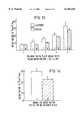
- FIG. 15is a diagrammatic view of a pin used for testing
- FIG. 16is a diagrammatic view of a plate used for testing
- FIG. 17is a diagrammatic perspective view of another method of making material for the bearing elements.
- FIG. 18is a diagrammatic side elevation of a third method of making material for the bearing elements.
- FIGS. 1 and 2show a typical tibial tray for use in a prosthetic implant.
- the traycomprises a base portion 1, the outer circumference 2 of which is provided with an upstanding lip 3.
- a spigot 4extends downwardly from the base 1 to provide attachment to the bone in which it is inserted.
- the base 1carries a bearing element 5 which has spaced apart indentations to accept the condyles of the femoral implant (not shown).
- Tibial trays of this kindare well known in themselves and the construction will not therefore be described further.
- the bearing element 5is made from ultra high molecular weight polyethylene (UHMWPE) with a molecular weight greater than 1,000,000 and with a multi-axially molecular orientation.
- UHMWPEultra high molecular weight polyethylene
- FIG. 3shows an alternative form of tibial tray and the same reference numerals are used to indicate similar parts, but in this construction the base 1 is provided with two separate bearing elements 7 and 8 which are located in recesses 9 and 10.
- the bearing elementseach of which has a bearing surface 11, are made from an UHMWPE with a molecular weight greater than 1,000,000 with a multi-axially molecular orientation.
- the direction of one of said axial molecular orientationsextends parallel with or along the length of the bearing surface, thus, it could extend in a substantially horizontal direction and along the length of the indentation 6 or bearing surfaces 11 along a substantially medio lateral plane.
- a second molecular orientationmay extend at right angles thereto, again, substantially horizontal, or it could extend vertically through the bearing element. Again, a combination of various directions can be used.
- FIG. 4shows another knee prosthesis, but in this arrangement a tray 15 is provided on the tibia on which is carried a pair of sliding meniscal bearing elements 16.
- the upper surface of the element 16is engaged by a femoral implant 17 on which is also carried a patella implant 18 having a metal backing which engages the patella remnant 19.
- a patella bearing element 20is arranged between the metal backing and the femoral implant 17.
- the bearing elements 16each have a proximal bearing surface 21 which engages the bearing surface 22 on the femoral implant 19 and further bearing surfaces 23 which engage bearing surfaces 24 on the tray 15.
- the patella element 20has a bearing surface 25 which engages the bearing surface 22 on the femoral implant 14 and a further bearing surface 26 which engages the metallic backing.
- the bearing elements 16 and 20are made from an UHMWPE with a molecular weight greater than 1,000,000 with a multi-axially molecular orientation.
- the orientationscan be as described with regard to FIGS. 1, 2 and 3.
- FIG. 5shows a hip prosthesis which comprises a femoral insert 30 provided with the usual ball 31.
- the ballseats in a hip cup 32 which comprises a metallic backing 33 designed for location by any convenient means, for example, cement or mechanical means to the pelvis and which carries a bearing element in the form of a liner 34.
- the liner 34is made from an UHMWPE with a molecular weight greater than 1,000,000 and the multi-axially molecular orientation in the liner 34 and can again be in any way desired and as referred to with regard to FIGS. 1, 2 and 3. It has been found that a preferred molecular weight is greater than 4,000,000.
- the first methoddemonstrates die drawing of molecular weight 4.5 million UHMWPE in both uniaxial and biaxial forms.
- the drawn materialshad similar density and crystallinity as shown in FIGS. 6 and 7 to the isotropic source material.
- the molecular orientation of the drawn materialwas confirmed by X-ray diffraction.
- the materialis intended for use as polymer components in artificial joints as set forth above, which undergo complex loading regimes, stress field and wear patterns, it is considered preferable to enhance the properties of the UHMWPE in two directions, by using biaxial drawing methods.
- FIG. 8shows a method used for biaxial orientation of a thick walled tube 41, by drawing a material 42 over a mandrel 43 which is of increasing diameter over its length in the direction of draw indicated by reference numeral 44.
- a method of drawing polyethylene material to produce solid phase deformationis described in GB 2 225 551, the teaching of which is incorporated herein, but the effects produced by the present method were unexpected considering the information set out, for example, in the prior art document referred to above.
- This methodproduces orientation in both the longitudinal direction indicated by arrow 45 and hoop direction indicated by arrow 46, as shown in FIGS. 8 and 9, with a higher draw deformation ratio and orientation near the internal surface of the tube 47 than the outside 48 in the hoop direction 46.
- Materialis produced such that the draw ratios close to the internal surface 47 is similar in magnitude in both the hoop 46 and longitudinal direction 45.
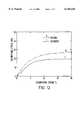
- FIG. 10shows typical engineering stress strain curves taken in tension in the longitudinal direction for the isotropic or standard material (A) and biaxially orientated material (B) with a draw ratio of 1.5 in each direction. This shows that the drawn material had a reduction in the strain to failure, approximately similar strain energy to failure and a higher proof stress and working stress range compared to the isotropic material. Increasing the draw ratio further adversely affected both the strain and strain energy to failure, producing a much more brittle material as shown in the curve for the highly drawn uniaxial material with a ratio of 4 to 1 as shown in FIG. 10.
- Biaxially drawn material with a draw ratio of approximately 1.5 in each directionwas considered to produce the most appropriate change in properties with a statistically significant increase in proof stress and working stress range while maintaining a similar strain energy to failure and elastic modulus to the isotropic material as shown in FIG. 11.
- a detailed examination of the stress strain curve for the two materials at low strainsshows clearly the improved characteristics of the biaxially oriented material as shown in FIG. 12.
- the first test configurationmay be considered more appropriate for hip joint applications, while the second test may be considered more suited to knee joint applications.
- the polymer pins and plateswere taken with their wear surfaces close to the internal diameter of the drawn tube, where the draw ratio was approximately 1.5 in each direction, such a pin 49 and a plate 50 are shown in FIG. 9.
- Each testconsisted of direct comparison between the biaxial material and the isotropic control material. Tests were carried out for sliding distances greater than 250 km (greater than 10 years equivalent), with more than 15 measurements in each test to allow statistical analysis. Tests were run in bovine serum as a lubricant, and the wear rate was expressed as a normalized wear factor K when, ##EQU1##
- the biaxial materialhas a lower wear rate than the isotropic control material. The differences were statistically significant at the 20% level in Tests 2 and 3. Overall, the wear factor for the biaxial material was reduced by 22% compared to the isotropic material.
- the results for the polymer plate 50 on a pin testare shown in FIG. 14.
- the isotropic materialshowed a higher wear factor than the biaxial material and this was statistically significant at the 5% level.
- the biaxial drawing of the materialwas predicted to produce a 25% reduction in the wear rate of this test.
- FIGS. 15 and 16are intended to illustrate what is thought to be the lines of molecular orientation on the test pieces.
- FIG. 15shows the work surface 49a on the end of the pin 49.
- the general direction of the molecular orientationis shown to be in two directions by arrows A and B.
- the point from which the pin has been takenis shown in FIG. 9 and it will be seen that the lines of orientation are substantially at right angles to each other across the surface.
- FIG. 16the lines of orientation are again shown in two directions C and D on one face 51a of the plate 50. It will be seen that the lines of orientation are at right angles on this face. On the face 51b however, although the lines of orientation C and D are again at right angles, the lines D exhibit their ends towards the face and on the face 51c the lines of orientation D extend across the face, but the lines C again exhibit their ends.
- An alternative method of causing solid phase deformation in at least two directions to UHMWPEcan be applied by a slot type drawing method.
- a rectangular or square strip of pre-machined UHMWPE 52is drawn through a slot 53 of a slot-type die 54 having an entry opening 55 and a discharge opening 56.
- the direction of drawis indicated by arrow 57 and the transverse width of the slot 53 is equivalent to the transverse width of the strip 52 at entry.
- FIG. 18shows a method similar to that described and shown in FIG. 8 and the same reference numerals are used to indicate similar parts but in this method the tube of material also passes through a control die 60.
Landscapes
- Health & Medical Sciences (AREA)
- Transplantation (AREA)
- Veterinary Medicine (AREA)
- Life Sciences & Earth Sciences (AREA)
- Engineering & Computer Science (AREA)
- Public Health (AREA)
- General Health & Medical Sciences (AREA)
- Oral & Maxillofacial Surgery (AREA)
- Orthopedic Medicine & Surgery (AREA)
- Animal Behavior & Ethology (AREA)
- Biomedical Technology (AREA)
- Vascular Medicine (AREA)
- Heart & Thoracic Surgery (AREA)
- Cardiology (AREA)
- Chemical & Material Sciences (AREA)
- Mechanical Engineering (AREA)
- Physical Education & Sports Medicine (AREA)
- Chemical Kinetics & Catalysis (AREA)
- Dermatology (AREA)
- Medicinal Chemistry (AREA)
- Epidemiology (AREA)
- Prostheses (AREA)
- Materials For Medical Uses (AREA)
Abstract
Description
______________________________________ Polymer Pin on Plate Wear Tests ______________________________________ 1200N Load 2160N Load 3160N Load 480N Load 5 80N Load (rough interface) ______________________________________
Claims (11)
Applications Claiming Priority (2)
| Application Number | Priority Date | Filing Date | Title |
|---|---|---|---|
| GB9522478 | 1995-11-02 | ||
| GBGB9522478.8AGB9522478D0 (en) | 1995-11-02 | 1995-11-02 | Prosthetic bearing element and implant incorporating such an element |
Publications (1)
| Publication Number | Publication Date |
|---|---|
| US6146426Atrue US6146426A (en) | 2000-11-14 |
Family
ID=10783300
Family Applications (1)
| Application Number | Title | Priority Date | Filing Date |
|---|---|---|---|
| US08/742,540Expired - LifetimeUS6146426A (en) | 1995-11-02 | 1996-11-01 | Prosthetic polyethylene bearing having enhanced wear properties |
Country Status (7)
| Country | Link |
|---|---|
| US (1) | US6146426A (en) |
| EP (1) | EP0771551B1 (en) |
| JP (1) | JPH1094597A (en) |
| AT (1) | ATE231368T1 (en) |
| AU (1) | AU713414B2 (en) |
| DE (1) | DE69625876T2 (en) |
| GB (1) | GB9522478D0 (en) |
Cited By (12)
| Publication number | Priority date | Publication date | Assignee | Title |
|---|---|---|---|---|
| US20030003127A1 (en)* | 2001-06-27 | 2003-01-02 | Ethicon, Inc. | Porous ceramic/porous polymer layered scaffolds for the repair and regeneration of tissue |
| US6626950B2 (en)* | 2001-06-28 | 2003-09-30 | Ethicon, Inc. | Composite scaffold with post anchor for the repair and regeneration of tissue |
| US20040193282A1 (en)* | 2003-03-31 | 2004-09-30 | Hanes Mark D. | Reduced wear orthopaedic implant apparatus and method |
| US20060079596A1 (en)* | 2004-10-07 | 2006-04-13 | Schroeder David W | Crosslinked polymeric material with enhanced strength and process for manufacturing |
| US20060079595A1 (en)* | 2004-10-07 | 2006-04-13 | Schroeder David W | Solid state deformation processing of crosslinked high molecular weight polymeric materials |
| US20080149299A1 (en)* | 2006-12-20 | 2008-06-26 | Victor Blakemore Slaughter | Method of using minimal surfaces and minimal skeletons to make heat exchanger components |
| US7547405B2 (en) | 2004-10-07 | 2009-06-16 | Biomet Manufacturing Corp. | Solid state deformation processing of crosslinked high molecular weight polymeric materials |
| US8262976B2 (en) | 2004-10-07 | 2012-09-11 | Biomet Manufacturing Corp. | Solid state deformation processing of crosslinked high molecular weight polymeric materials |
| US8641959B2 (en) | 2007-07-27 | 2014-02-04 | Biomet Manufacturing, Llc | Antioxidant doping of crosslinked polymers to form non-eluting bearing components |
| USRE44762E1 (en) | 1994-09-21 | 2014-02-11 | Bmg Incorporated | Ultra high molecular weight polyethylene molded article for artificial joints and method of preparing the same |
| US9586370B2 (en) | 2013-08-15 | 2017-03-07 | Biomet Manufacturing, Llc | Method for making ultra high molecular weight polyethylene |
| DE102016207205A1 (en)* | 2016-04-27 | 2017-11-02 | Ceramtec Gmbh | Tibial component for a knee endoprosthesis with two PE liners |
Citations (8)
| Publication number | Priority date | Publication date | Assignee | Title |
|---|---|---|---|---|
| GB2060469B (en)* | 1979-06-06 | 1983-09-28 | Nat Res Dev | Drawing thermoplastics material |
| US4655769A (en)* | 1984-10-24 | 1987-04-07 | Zachariades Anagnostis E | Ultra-high-molecular-weight polyethylene products including vascular prosthesis devices and methods relating thereto and employing pseudo-gel states |
| GB2156733B (en)* | 1984-03-30 | 1987-10-28 | Nat Res Dev | Die drawing of tubular thermoplastics |
| US4747990A (en)* | 1985-03-12 | 1988-05-31 | Cie Oris Industrie S.A. | Process of making a high molecular weight polyolefin part |
| EP0371769A2 (en)* | 1988-11-30 | 1990-06-06 | Btg International Limited | Tubular materials |
| DE4006714A1 (en)* | 1989-03-09 | 1990-09-13 | Bristol Myers Squibb Co | COMPONENT OF AN ORTHOPEDIC IMPLANT AND METHOD FOR THE PRODUCTION THEREOF |
| US5030402A (en)* | 1989-03-17 | 1991-07-09 | Zachariades Anagnostis E | Process for producing a new class of ultra-high-molecular-weight polyethylene orthopaedic prostheses with enhanced mechanical properties |
| US5609638A (en)* | 1994-11-29 | 1997-03-11 | Zimmer, Inc. | Reinforced polyethylene for articular surfaces |
- 1995
- 1995-11-02GBGBGB9522478.8Apatent/GB9522478D0/enactivePending
- 1996
- 1996-10-28AUAU70444/96Apatent/AU713414B2/ennot_activeCeased
- 1996-10-30DEDE69625876Tpatent/DE69625876T2/ennot_activeExpired - Fee Related
- 1996-10-30ATAT96307862Tpatent/ATE231368T1/ennot_activeIP Right Cessation
- 1996-10-30EPEP96307862Apatent/EP0771551B1/ennot_activeExpired - Lifetime
- 1996-11-01USUS08/742,540patent/US6146426A/ennot_activeExpired - Lifetime
- 1996-11-05JPJP8292428Apatent/JPH1094597A/enactivePending
Patent Citations (10)
| Publication number | Priority date | Publication date | Assignee | Title |
|---|---|---|---|---|
| GB2060469B (en)* | 1979-06-06 | 1983-09-28 | Nat Res Dev | Drawing thermoplastics material |
| GB2156733B (en)* | 1984-03-30 | 1987-10-28 | Nat Res Dev | Die drawing of tubular thermoplastics |
| US4801419A (en)* | 1984-03-30 | 1989-01-31 | National Research Development Corporation | Solid phase deformation of thermoplastic tubes |
| US4655769A (en)* | 1984-10-24 | 1987-04-07 | Zachariades Anagnostis E | Ultra-high-molecular-weight polyethylene products including vascular prosthesis devices and methods relating thereto and employing pseudo-gel states |
| US4747990A (en)* | 1985-03-12 | 1988-05-31 | Cie Oris Industrie S.A. | Process of making a high molecular weight polyolefin part |
| EP0371769A2 (en)* | 1988-11-30 | 1990-06-06 | Btg International Limited | Tubular materials |
| GB2225551B (en)* | 1988-11-30 | 1993-02-03 | Nat Res Dev | Tubular materials |
| DE4006714A1 (en)* | 1989-03-09 | 1990-09-13 | Bristol Myers Squibb Co | COMPONENT OF AN ORTHOPEDIC IMPLANT AND METHOD FOR THE PRODUCTION THEREOF |
| US5030402A (en)* | 1989-03-17 | 1991-07-09 | Zachariades Anagnostis E | Process for producing a new class of ultra-high-molecular-weight polyethylene orthopaedic prostheses with enhanced mechanical properties |
| US5609638A (en)* | 1994-11-29 | 1997-03-11 | Zimmer, Inc. | Reinforced polyethylene for articular surfaces |
Non-Patent Citations (2)
| Title |
|---|
| "Elastic Moduli of Highly Oriented Polyoxymethylene" by C.L. Choy et al, in Polymer Engineering & Science, Nov. 1983, vol. 26, #16 pp. 910-922. |
| Elastic Moduli of Highly Oriented Polyoxymethylene by C.L. Choy et al, in Polymer Engineering & Science, Nov. 1983, vol. 26, 16 pp. 910 922.* |
Cited By (23)
| Publication number | Priority date | Publication date | Assignee | Title |
|---|---|---|---|---|
| USRE44762E1 (en) | 1994-09-21 | 2014-02-11 | Bmg Incorporated | Ultra high molecular weight polyethylene molded article for artificial joints and method of preparing the same |
| US20030003127A1 (en)* | 2001-06-27 | 2003-01-02 | Ethicon, Inc. | Porous ceramic/porous polymer layered scaffolds for the repair and regeneration of tissue |
| US6626950B2 (en)* | 2001-06-28 | 2003-09-30 | Ethicon, Inc. | Composite scaffold with post anchor for the repair and regeneration of tissue |
| US7108720B2 (en) | 2003-03-31 | 2006-09-19 | Depuy Products, Inc. | Reduced wear orthopaedic implant apparatus and method |
| US20040193282A1 (en)* | 2003-03-31 | 2004-09-30 | Hanes Mark D. | Reduced wear orthopaedic implant apparatus and method |
| US7780896B2 (en) | 2004-10-07 | 2010-08-24 | Biomet Manufacturing Corp. | Crosslinked polymeric material with enhanced strength and process for manufacturing |
| US8137608B2 (en) | 2004-10-07 | 2012-03-20 | Biomet Manufacturing Corp. | Crosslinked polymeric material with enhanced strength and process for manufacturing |
| US9017590B2 (en) | 2004-10-07 | 2015-04-28 | Biomet Manufacturing, Llc | Solid state deformation processing of crosslinked high molecular weight polymeric materials |
| US7462318B2 (en) | 2004-10-07 | 2008-12-09 | Biomet Manufacturing Corp. | Crosslinked polymeric material with enhanced strength and process for manufacturing |
| US7547405B2 (en) | 2004-10-07 | 2009-06-16 | Biomet Manufacturing Corp. | Solid state deformation processing of crosslinked high molecular weight polymeric materials |
| US20060079595A1 (en)* | 2004-10-07 | 2006-04-13 | Schroeder David W | Solid state deformation processing of crosslinked high molecular weight polymeric materials |
| US20060079596A1 (en)* | 2004-10-07 | 2006-04-13 | Schroeder David W | Crosslinked polymeric material with enhanced strength and process for manufacturing |
| US7927536B2 (en) | 2004-10-07 | 2011-04-19 | Biomet Manufacturing Corp. | Solid state deformation processing of crosslinked high molecular weight polymeric materials |
| US7993401B2 (en) | 2004-10-07 | 2011-08-09 | Biomet Manufacturing Corp. | Solid state deformation processing of crosslinked high molecular weight polymeric materials |
| US7344672B2 (en) | 2004-10-07 | 2008-03-18 | Biomet Manufacturing Corp. | Solid state deformation processing of crosslinked high molecular weight polymeric materials |
| US8262976B2 (en) | 2004-10-07 | 2012-09-11 | Biomet Manufacturing Corp. | Solid state deformation processing of crosslinked high molecular weight polymeric materials |
| US8398913B2 (en) | 2004-10-07 | 2013-03-19 | Biomet Manufacturing Corp. | Solid state deformation processing of crosslinked high molecular weight polymeric materials |
| US7866377B2 (en)* | 2006-12-20 | 2011-01-11 | The Boeing Company | Method of using minimal surfaces and minimal skeletons to make heat exchanger components |
| US20080149299A1 (en)* | 2006-12-20 | 2008-06-26 | Victor Blakemore Slaughter | Method of using minimal surfaces and minimal skeletons to make heat exchanger components |
| US8641959B2 (en) | 2007-07-27 | 2014-02-04 | Biomet Manufacturing, Llc | Antioxidant doping of crosslinked polymers to form non-eluting bearing components |
| US9421104B2 (en) | 2007-07-27 | 2016-08-23 | Biomet Manufacturing, Llc | Antioxidant doping of crosslinked polymers to form non-eluting bearing components |
| US9586370B2 (en) | 2013-08-15 | 2017-03-07 | Biomet Manufacturing, Llc | Method for making ultra high molecular weight polyethylene |
| DE102016207205A1 (en)* | 2016-04-27 | 2017-11-02 | Ceramtec Gmbh | Tibial component for a knee endoprosthesis with two PE liners |
Also Published As
| Publication number | Publication date |
|---|---|
| EP0771551A2 (en) | 1997-05-07 |
| DE69625876T2 (en) | 2003-08-07 |
| AU713414B2 (en) | 1999-12-02 |
| ATE231368T1 (en) | 2003-02-15 |
| JPH1094597A (en) | 1998-04-14 |
| DE69625876D1 (en) | 2003-02-27 |
| GB9522478D0 (en) | 1996-01-03 |
| EP0771551B1 (en) | 2003-01-22 |
| AU7044496A (en) | 1997-05-08 |
| EP0771551A3 (en) | 1997-11-12 |
Similar Documents
| Publication | Publication Date | Title |
|---|---|---|
| US6146426A (en) | Prosthetic polyethylene bearing having enhanced wear properties | |
| EP1223895B1 (en) | Composite bearing inserts for total knee joints | |
| Semlitsch et al. | New prospects for a prolonged functional life‐span of artificial hip joints by using the material combination polyethylene/aluminium oxide ceramic/metal | |
| US6436145B1 (en) | Plug for a modular orthopaedic implant and method for assembly | |
| Cook et al. | Corrosion and wear at the modular interface of uncemented femoral stems | |
| Galante et al. | Fiber metal composites in the fixation of skeletal prosthesis | |
| US8323346B2 (en) | Wear-reducing geometry of articulations in total joint replacements | |
| US5609647A (en) | Spherical hip joint socket | |
| US5964809A (en) | Polyetheretherketone (PEEK) retaining ring for an acetabular cup assembly | |
| DE69632145T2 (en) | BALL AND PAN JOINT PROSTHESIS WITH LOW WEAR | |
| Oonishi et al. | Ceramic versus cobalt-chrome femoral components; wear of polyethylene insert in total knee prosthesis | |
| US6911100B1 (en) | Method for controlling residual stress in prosthetics | |
| Bhatt et al. | Implant wear mechanisms—basic approach | |
| JP2018038906A (en) | Receptacle | |
| US20040148033A1 (en) | Wear surface for metal-on-metal articulation | |
| DiRienzo et al. | Porous poly (para-phenylene) scaffolds for load-bearing orthopedic applications | |
| Pruitt et al. | Effect of sterilization on the structure and fatigue resistance of medical grade UHMWPE | |
| Ovaert | On the wear behavior of longitudinally (parallel) oriented unidirectional fiber-reinforced polymer composites | |
| OH et al. | Acetabular cup groove and pod design and its effect on cement fixation in total hip arthroplasty | |
| Ioannidis et al. | Long-term behaviour of the Charnley offset-bore acetabular cup | |
| Todo et al. | Effect of sliding locus on subsurface crack formation in ultra‐high‐molecular‐weight polyethylene knee component | |
| EP2338444A1 (en) | Method for manufacturing an orthopedic implant | |
| Barker et al. | A circumferentially flanged tibial tray minimizes bone-tray shear micromotion | |
| Silva et al. | Polyethylene in total knee arthroplasty | |
| Döring et al. | Reduction of Micro‐Motion at the Tapered Connection of Hip Endoprostheses with an Adapted Deep Rolling Process of CoCrMo Inner Tapers |
Legal Events
| Date | Code | Title | Description |
|---|---|---|---|
| AS | Assignment | Owner name:HOWMEDICA INTERNATIONAL INC., IRELAND Free format text:ASSIGNMENT OF ASSIGNORS INTEREST;ASSIGNOR:DOYLE, CHRISTINA;REEL/FRAME:008383/0625 Effective date:19970213 | |
| STCF | Information on status: patent grant | Free format text:PATENTED CASE | |
| AS | Assignment | Owner name:HOWMEDICA INTERNATIONAL S. DE R.L., PANAMA Free format text:CHANGE OF NAME;ASSIGNOR:HOWMEDICA INTERNATIONAL INC.;REEL/FRAME:011731/0705 Effective date:19981113 | |
| CC | Certificate of correction | ||
| FPAY | Fee payment | Year of fee payment:4 | |
| FEPP | Fee payment procedure | Free format text:PAYOR NUMBER ASSIGNED (ORIGINAL EVENT CODE: ASPN); ENTITY STATUS OF PATENT OWNER: LARGE ENTITY | |
| FPAY | Fee payment | Year of fee payment:8 | |
| FPAY | Fee payment | Year of fee payment:12 | |
| AS | Assignment | Owner name:STRYKER MEDTECH LIMITED, MALTA Free format text:NUNC PRO TUNC ASSIGNMENT;ASSIGNOR:HOWMEDICA INTERNATIONAL S. DE R.L.;REEL/FRAME:037118/0895 Effective date:20151013 Owner name:STRYKER EUROPEAN HOLDINGS I, LLC, MICHIGAN Free format text:NUNC PRO TUNC ASSIGNMENT;ASSIGNOR:STRYKER MEDTECH LIMITED;REEL/FRAME:037153/0241 Effective date:20151013 | |
| AS | Assignment | Owner name:STRYKER EUROPEAN HOLDINGS I, LLC, MICHIGAN Free format text:CORRECTIVE ASSIGNMENT TO CORRECT THE INCORRECT LISTED SERIAL NOS. 09/905,670 AND 07/092,079 PREVIOUSLY RECORDED AT REEL: 037153 FRAME: 0241. ASSIGNOR(S) HEREBY CONFIRMS THE NUNC PRO TUNC ASSIGNMENT EFFECTIVE DATE 9/29/2014;ASSIGNOR:STRYKER MEDTECH LIMITED;REEL/FRAME:038043/0011 Effective date:20151013 | |
| AS | Assignment | Owner name:STRYKER EUROPEAN OPERATIONS HOLDINGS LLC, MICHIGAN Free format text:CHANGE OF NAME;ASSIGNOR:STRYKER EUROPEAN HOLDINGS III, LLC;REEL/FRAME:052860/0716 Effective date:20190226 Owner name:STRYKER EUROPEAN HOLDINGS III, LLC, DELAWARE Free format text:NUNC PRO TUNC ASSIGNMENT;ASSIGNOR:STRYKER EUROPEAN HOLDINGS I, LLC;REEL/FRAME:052861/0001 Effective date:20200519 |