US6146325A - Ventricular assist device - Google Patents
Ventricular assist deviceDownload PDFInfo
- Publication number
- US6146325A US6146325AUS09/325,334US32533499AUS6146325AUS 6146325 AUS6146325 AUS 6146325AUS 32533499 AUS32533499 AUS 32533499AUS 6146325 AUS6146325 AUS 6146325A
- Authority
- US
- United States
- Prior art keywords
- chamber
- liquid
- vad
- gas
- tube
- Prior art date
- Legal status (The legal status is an assumption and is not a legal conclusion. Google has not performed a legal analysis and makes no representation as to the accuracy of the status listed.)
- Expired - Lifetime
Links
- 230000002861ventricularEffects0.000titledescription3
- 239000007788liquidSubstances0.000claimsabstractdescription94
- 238000004891communicationMethods0.000claimsabstractdescription27
- 229920000642polymerPolymers0.000claimsabstractdescription27
- 238000007920subcutaneous administrationMethods0.000claimsabstractdescription14
- 210000000709aortaAnatomy0.000claimsabstractdescription13
- 239000000463materialSubstances0.000claimsdescription14
- RTAQQCXQSZGOHL-UHFFFAOYSA-NTitaniumChemical compound[Ti]RTAQQCXQSZGOHL-UHFFFAOYSA-N0.000claimsdescription7
- 239000010936titaniumSubstances0.000claimsdescription7
- 229910052719titaniumInorganic materials0.000claimsdescription7
- 238000002788crimpingMethods0.000claimsdescription3
- 230000007704transitionEffects0.000claimsdescription3
- 239000004721Polyphenylene oxideSubstances0.000claims1
- OYQYHJRSHHYEIG-UHFFFAOYSA-Nethyl carbamate;ureaChemical compoundNC(N)=O.CCOC(N)=OOYQYHJRSHHYEIG-UHFFFAOYSA-N0.000claims1
- 229920000570polyetherPolymers0.000claims1
- 239000008280bloodSubstances0.000abstractdescription26
- 210000004369bloodAnatomy0.000abstractdescription26
- 238000009958sewingMethods0.000abstractdescription3
- 239000007789gasSubstances0.000description52
- 210000005242cardiac chamberAnatomy0.000description10
- 210000005240left ventricleAnatomy0.000description10
- 238000001802infusionMethods0.000description7
- 230000006870functionEffects0.000description5
- 210000004165myocardiumAnatomy0.000description5
- 238000005299abrasionMethods0.000description3
- 230000000747cardiac effectEffects0.000description3
- 230000004217heart functionEffects0.000description3
- 210000005241right ventricleAnatomy0.000description3
- 206010007559Cardiac failure congestiveDiseases0.000description2
- 206010019280Heart failuresDiseases0.000description2
- 230000006378damageEffects0.000description2
- 238000013461designMethods0.000description2
- 230000005484gravityEffects0.000description2
- 239000007943implantSubstances0.000description2
- 230000006698inductionEffects0.000description2
- 230000001939inductive effectEffects0.000description2
- 208000015181infectious diseaseDiseases0.000description2
- 210000005246left atriumAnatomy0.000description2
- 230000007246mechanismEffects0.000description2
- 238000000034methodMethods0.000description2
- 230000002685pulmonary effectEffects0.000description2
- 230000008672reprogrammingEffects0.000description2
- 229920004934Dacron®Polymers0.000description1
- 206010018910HaemolysisDiseases0.000description1
- 208000007536ThrombosisDiseases0.000description1
- 230000004071biological effectEffects0.000description1
- 230000008859changeEffects0.000description1
- 230000006835compressionEffects0.000description1
- 238000007906compressionMethods0.000description1
- 238000010276constructionMethods0.000description1
- 239000002537cosmeticSubstances0.000description1
- 230000003247decreasing effectEffects0.000description1
- 230000007812deficiencyEffects0.000description1
- 230000000994depressogenic effectEffects0.000description1
- 230000003205diastolic effectEffects0.000description1
- 238000009792diffusion processMethods0.000description1
- 238000006073displacement reactionMethods0.000description1
- 230000000694effectsEffects0.000description1
- 230000008588hemolysisEffects0.000description1
- 238000002513implantationMethods0.000description1
- 238000001727in vivoMethods0.000description1
- 230000002452interceptive effectEffects0.000description1
- 230000007774longtermEffects0.000description1
- 238000004519manufacturing processMethods0.000description1
- 238000013160medical therapyMethods0.000description1
- 229910052751metalInorganic materials0.000description1
- 239000002184metalSubstances0.000description1
- 238000012986modificationMethods0.000description1
- 230000004048modificationEffects0.000description1
- 238000013021overheatingMethods0.000description1
- 239000004033plasticSubstances0.000description1
- 239000005020polyethylene terephthalateSubstances0.000description1
- 229920001343polytetrafluoroethylenePolymers0.000description1
- 239000004810polytetrafluoroethyleneSubstances0.000description1
- 230000008569processEffects0.000description1
- 210000003492pulmonary veinAnatomy0.000description1
- 230000000541pulsatile effectEffects0.000description1
- 238000011084recoveryMethods0.000description1
- 210000005245right atriumAnatomy0.000description1
- 239000013589supplementSubstances0.000description1
- 230000008337systemic blood flowEffects0.000description1
- 238000012360testing methodMethods0.000description1
- 230000000451tissue damageEffects0.000description1
- 231100000827tissue damageToxicity0.000description1
- 238000002054transplantationMethods0.000description1
- 238000012800visualizationMethods0.000description1
- XLYOFNOQVPJJNP-UHFFFAOYSA-NwaterSubstancesOXLYOFNOQVPJJNP-UHFFFAOYSA-N0.000description1
Images


Classifications
- A—HUMAN NECESSITIES
- A61—MEDICAL OR VETERINARY SCIENCE; HYGIENE
- A61M—DEVICES FOR INTRODUCING MEDIA INTO, OR ONTO, THE BODY; DEVICES FOR TRANSDUCING BODY MEDIA OR FOR TAKING MEDIA FROM THE BODY; DEVICES FOR PRODUCING OR ENDING SLEEP OR STUPOR
- A61M1/00—Suction or pumping devices for medical purposes; Devices for carrying-off, for treatment of, or for carrying-over, body-liquids; Drainage systems
- A61M1/36—Other treatment of blood in a by-pass of the natural circulatory system, e.g. temperature adaptation, irradiation ; Extra-corporeal blood circuits
- A61M1/3621—Extra-corporeal blood circuits
- A61M1/3653—Interfaces between patient blood circulation and extra-corporal blood circuit
- A61M1/3659—Cannulae pertaining to extracorporeal circulation
- A—HUMAN NECESSITIES
- A61—MEDICAL OR VETERINARY SCIENCE; HYGIENE
- A61M—DEVICES FOR INTRODUCING MEDIA INTO, OR ONTO, THE BODY; DEVICES FOR TRANSDUCING BODY MEDIA OR FOR TAKING MEDIA FROM THE BODY; DEVICES FOR PRODUCING OR ENDING SLEEP OR STUPOR
- A61M60/00—Blood pumps; Devices for mechanical circulatory actuation; Balloon pumps for circulatory assistance
- A61M60/10—Location thereof with respect to the patient's body
- A61M60/104—Extracorporeal pumps, i.e. the blood being pumped outside the patient's body
- A—HUMAN NECESSITIES
- A61—MEDICAL OR VETERINARY SCIENCE; HYGIENE
- A61M—DEVICES FOR INTRODUCING MEDIA INTO, OR ONTO, THE BODY; DEVICES FOR TRANSDUCING BODY MEDIA OR FOR TAKING MEDIA FROM THE BODY; DEVICES FOR PRODUCING OR ENDING SLEEP OR STUPOR
- A61M60/00—Blood pumps; Devices for mechanical circulatory actuation; Balloon pumps for circulatory assistance
- A61M60/10—Location thereof with respect to the patient's body
- A61M60/122—Implantable pumps or pumping devices, i.e. the blood being pumped inside the patient's body
- A61M60/126—Implantable pumps or pumping devices, i.e. the blood being pumped inside the patient's body implantable via, into, inside, in line, branching on, or around a blood vessel
- A61M60/148—Implantable pumps or pumping devices, i.e. the blood being pumped inside the patient's body implantable via, into, inside, in line, branching on, or around a blood vessel in line with a blood vessel using resection or like techniques, e.g. permanent endovascular heart assist devices
- A—HUMAN NECESSITIES
- A61—MEDICAL OR VETERINARY SCIENCE; HYGIENE
- A61M—DEVICES FOR INTRODUCING MEDIA INTO, OR ONTO, THE BODY; DEVICES FOR TRANSDUCING BODY MEDIA OR FOR TAKING MEDIA FROM THE BODY; DEVICES FOR PRODUCING OR ENDING SLEEP OR STUPOR
- A61M60/00—Blood pumps; Devices for mechanical circulatory actuation; Balloon pumps for circulatory assistance
- A61M60/10—Location thereof with respect to the patient's body
- A61M60/122—Implantable pumps or pumping devices, i.e. the blood being pumped inside the patient's body
- A61M60/165—Implantable pumps or pumping devices, i.e. the blood being pumped inside the patient's body implantable in, on, or around the heart
- A61M60/178—Implantable pumps or pumping devices, i.e. the blood being pumped inside the patient's body implantable in, on, or around the heart drawing blood from a ventricle and returning the blood to the arterial system via a cannula external to the ventricle, e.g. left or right ventricular assist devices
- A—HUMAN NECESSITIES
- A61—MEDICAL OR VETERINARY SCIENCE; HYGIENE
- A61M—DEVICES FOR INTRODUCING MEDIA INTO, OR ONTO, THE BODY; DEVICES FOR TRANSDUCING BODY MEDIA OR FOR TAKING MEDIA FROM THE BODY; DEVICES FOR PRODUCING OR ENDING SLEEP OR STUPOR
- A61M60/00—Blood pumps; Devices for mechanical circulatory actuation; Balloon pumps for circulatory assistance
- A61M60/20—Type thereof
- A61M60/247—Positive displacement blood pumps
- A61M60/253—Positive displacement blood pumps including a displacement member directly acting on the blood
- A61M60/268—Positive displacement blood pumps including a displacement member directly acting on the blood the displacement member being flexible, e.g. membranes, diaphragms or bladders
- A—HUMAN NECESSITIES
- A61—MEDICAL OR VETERINARY SCIENCE; HYGIENE
- A61M—DEVICES FOR INTRODUCING MEDIA INTO, OR ONTO, THE BODY; DEVICES FOR TRANSDUCING BODY MEDIA OR FOR TAKING MEDIA FROM THE BODY; DEVICES FOR PRODUCING OR ENDING SLEEP OR STUPOR
- A61M60/00—Blood pumps; Devices for mechanical circulatory actuation; Balloon pumps for circulatory assistance
- A61M60/40—Details relating to driving
- A61M60/424—Details relating to driving for positive displacement blood pumps
- A61M60/427—Details relating to driving for positive displacement blood pumps the force acting on the blood contacting member being hydraulic or pneumatic
- A—HUMAN NECESSITIES
- A61—MEDICAL OR VETERINARY SCIENCE; HYGIENE
- A61M—DEVICES FOR INTRODUCING MEDIA INTO, OR ONTO, THE BODY; DEVICES FOR TRANSDUCING BODY MEDIA OR FOR TAKING MEDIA FROM THE BODY; DEVICES FOR PRODUCING OR ENDING SLEEP OR STUPOR
- A61M60/00—Blood pumps; Devices for mechanical circulatory actuation; Balloon pumps for circulatory assistance
- A61M60/80—Constructional details other than related to driving
- A61M60/855—Constructional details other than related to driving of implantable pumps or pumping devices
- A61M60/857—Implantable blood tubes
- A—HUMAN NECESSITIES
- A61—MEDICAL OR VETERINARY SCIENCE; HYGIENE
- A61M—DEVICES FOR INTRODUCING MEDIA INTO, OR ONTO, THE BODY; DEVICES FOR TRANSDUCING BODY MEDIA OR FOR TAKING MEDIA FROM THE BODY; DEVICES FOR PRODUCING OR ENDING SLEEP OR STUPOR
- A61M60/00—Blood pumps; Devices for mechanical circulatory actuation; Balloon pumps for circulatory assistance
- A61M60/80—Constructional details other than related to driving
- A61M60/855—Constructional details other than related to driving of implantable pumps or pumping devices
- A61M60/861—Connections or anchorings for connecting or anchoring pumps or pumping devices to parts of the patient's body
- A61M60/863—Apex rings
- A—HUMAN NECESSITIES
- A61—MEDICAL OR VETERINARY SCIENCE; HYGIENE
- A61M—DEVICES FOR INTRODUCING MEDIA INTO, OR ONTO, THE BODY; DEVICES FOR TRANSDUCING BODY MEDIA OR FOR TAKING MEDIA FROM THE BODY; DEVICES FOR PRODUCING OR ENDING SLEEP OR STUPOR
- A61M60/00—Blood pumps; Devices for mechanical circulatory actuation; Balloon pumps for circulatory assistance
- A61M60/80—Constructional details other than related to driving
- A61M60/855—Constructional details other than related to driving of implantable pumps or pumping devices
- A61M60/869—Compliance chambers containing a gas or liquid other than blood to compensate volume variations of a blood chamber
- A—HUMAN NECESSITIES
- A61—MEDICAL OR VETERINARY SCIENCE; HYGIENE
- A61M—DEVICES FOR INTRODUCING MEDIA INTO, OR ONTO, THE BODY; DEVICES FOR TRANSDUCING BODY MEDIA OR FOR TAKING MEDIA FROM THE BODY; DEVICES FOR PRODUCING OR ENDING SLEEP OR STUPOR
- A61M60/00—Blood pumps; Devices for mechanical circulatory actuation; Balloon pumps for circulatory assistance
- A61M60/80—Constructional details other than related to driving
- A61M60/855—Constructional details other than related to driving of implantable pumps or pumping devices
- A61M60/871—Energy supply devices; Converters therefor
- A61M60/873—Energy supply devices; Converters therefor specially adapted for wireless or transcutaneous energy transfer [TET], e.g. inductive charging
- A—HUMAN NECESSITIES
- A61—MEDICAL OR VETERINARY SCIENCE; HYGIENE
- A61M—DEVICES FOR INTRODUCING MEDIA INTO, OR ONTO, THE BODY; DEVICES FOR TRANSDUCING BODY MEDIA OR FOR TAKING MEDIA FROM THE BODY; DEVICES FOR PRODUCING OR ENDING SLEEP OR STUPOR
- A61M60/00—Blood pumps; Devices for mechanical circulatory actuation; Balloon pumps for circulatory assistance
- A61M60/80—Constructional details other than related to driving
- A61M60/855—Constructional details other than related to driving of implantable pumps or pumping devices
- A61M60/871—Energy supply devices; Converters therefor
- A61M60/876—Implantable batteries
- A—HUMAN NECESSITIES
- A61—MEDICAL OR VETERINARY SCIENCE; HYGIENE
- A61M—DEVICES FOR INTRODUCING MEDIA INTO, OR ONTO, THE BODY; DEVICES FOR TRANSDUCING BODY MEDIA OR FOR TAKING MEDIA FROM THE BODY; DEVICES FOR PRODUCING OR ENDING SLEEP OR STUPOR
- A61M2205/00—General characteristics of the apparatus
- A61M2205/82—Internal energy supply devices
- A61M2205/8237—Charging means
- A61M2205/8243—Charging means by induction
Definitions
- the present inventionrelates to a ventricular assist device (VAD), and more particularly to a VAD which is essentially implantable in a patient.
- VADventricular assist device
- VAD's and LVAD'sand especially VAD's and LVAD's which are more or less implantable within the body of a patient, are well known in the art.
- the LVADwas developed for the treatment of end stage congestive heart failure (CHF) in patients who are on maximal medical therapy and require long-term mechanical circulatory support, for example, patients who are not (temporarily or permanently) candidates for heart transplantation. Accordingly, the LVAD replaces or augments the function of the left ventricle in patients whose native left ventricles are unable to supply sufficient cardiac output to support a reasonable lifestyle, but whose right ventricle does function acceptably.
- the primary purpose of the LVADtherefore, is to provide systemic blood flow equal to that provided to it by the right heart. Secondarily, it should do so in a manner that drains the pulmonary veins and left atrium effectively, thereby avoiding pulmonary complications that would affect pulmonary or right heart function.
- VADcould be applied to replace or augment the function of the right ventricle.
- the VAD designapplies to both LVAD's and RVAD's.
- the implantable subsystems of the LVADinclude: inlet and outlet cannulae, blood pump, controller, internal coil, compliance chamber, and infusion port subsystems.
- the external or non-implantable subsystems of the LVADinclude: power transmitter (PT) with external coil, power pack, and battery charger.
- PTpower transmitter
- the implantable and external subsystemswork together to supplement the depressed cardiac-output state of a patient whose heart is failing.
- the gas passing between the blood pump and the compliance chambertypically carries with it entrained or dissolved liquid, such as moisture.
- This entrained or dissolved liquidseparates from the gas within the compliance chamber due to the temperature differential between the substantially spaced apart pump and compliance chamber, and under the influence of gravity accumulates at the bottom of the compliance chamber.
- the collected liquid at the bottom of the compliance chamberconsumes its volumetric space and reduces the functionality of the chamber, thereby decreasing the efficiency of the pump.
- the outlet cannulais connected to the blood pump at one end and to the aorta at the other end. If the outlet cannula is formed exclusively of polymer tubing, the anastomotic connection between the tube and the patient's aorta would be difficult. If the outlet cannula is formed exclusively of hard polymer tubing, then the outlet cannula is too rigid and lacks the flexibility to accommodate various movements of the patient during use. Accordingly, it is common practice to have an outlet cannula which comprises a hard polymer tubing commencing adjacent the pump and a relatively soft woven graft tubing (e.g., made of woven dacron, PTFE, etc.) adjacent to the aorta. Clearly, the securing together of the distal end of the hard polymer tubing and the proximal end of the graft tubing must provide a smooth transition and be easy to effect in manufacturing.
- an inlet cannulais connected to the blood pump at a proximal end and to a titanium tube entering a heart chamber (e.g., the left ventricle) at a distal end.
- a heart chambere.g., the left ventricle
- the distal end of the inlet cannulaincludes a sewable flexible apical cuff to facilitate attachment of the cannula to the heart chamber (e.g., the left ventricle) myocardium via surgical sewing.
- the means conventionally used for securing together the apical cuff and the titanium tubeare complex and unreliable. The securing means must be easily utilized during the surgical implantation procedure and establish a reliable connection thereafter as a failure of the connection would be critical.
- an object of the present inventionto provide an improved VAD and, more particular, an improved implantable VAD.
- Another objectis to provide a VAD enabling accumulated liquid within the compliance chamber to be withdrawn through a subcutaneous port.
- a further objectis to provide a VAD including means for easily and reliably securing together in the outlet cannula the hard polymer tubing and the woven graft tubing.
- VADwhich has means for draining accumulated liquid from the compliance chamber through a subcutaneous port, an inlet cannula having components which are easily and reliably secured together without relative rotation thereof, and means for easily and reliably securing together a tube entering the heart chamber (e.g., the left ventricle) and a sewable flexible apical cuff.
- VADvery simple and economical to assemble, implant and maintain.
- an implantable VADincluding a pump, a compliance chamber disposed above the pump, and a cannula connecting the pump and the compliance chamber in liquid and gaseous communication.
- the compliance chamberforms a reservoir for liquid extending from adjacent the bottom of the compliance chamber upwardly towards the top of the compliance chamber and a chamber for gas disposed above the liquid reservoir and extending upwardly to the top of the compliance chamber, the gas chamber being in gaseous communication with the pump via the cannula.
- a subcutaneous portis in liquid and gaseous communication with the liquid reservoir for introducing make-up gas into the gas chamber via the liquid reservoir and for removing accumulated liquid from the liquid reservoir.
- Conduit meansconnect the port and the liquid reservoir in liquid and gaseous communication.
- a weir disposed in the compliance chamberhas one end passing upwardly through the liquid reservoir and in gaseous communication with the gas chamber, and the other end in gaseous communication with the cannula.
- the conduit meansconnects the port and the bottom of the liquid reservoir, and the cannula connects the pump and the gas chamber above the top of the liquid reservoir.
- the top of the liquid reservoir and the bottom of the gas chamberare preferably the same.
- the present inventionalso encompasses an implantable VAD including an outlet cannula connected to a pump at a proximal end and to a tube adapted to enter the aorta at a distal end.
- the outlet cannulacomprises a hard polymer tubing commencing adjacent the pump and a relatively soft, woven graft tubing terminating adjacent the tube.
- a distal end of the hard polymer tubing and a proximal end of the graft tubingare secured together by a snap-fit connector formed of titanium.
- a strain relief materialis disposed substantially between portions of the graft tubing and the snap-fit connector, thereby to protect the graft tubing.
- the strain relief materialis preferably formed from a material similar to the hard polymer tubing.
- the present inventionadditionally encompasses an implantable VAD including a sewable flexible apical cuff adapted to be sewn to a portion of the heart (e.g., myocardium) and a rigid tube adapted to enter a chamber of the heart (e.g., the left ventricle).
- Means for securing together the cuff and tubecomprise a collet defining multiple radially compressible, circumferentially curved fingers, and a collar for radially inwardly moving the fingers to crimp a length of the cuff intermediate the collet and the tube onto the tube as the collar is rotated relative to the fingers from an initial relative orientation.
- the outer surface of the fingersdefines circumferentially spaced flats and the inner surface of the collar defines circumferentially spaced flats.
- the fingers and the collarhave an initial relative orientation such that the finger flats are radially aligned with the collar flats, and a final relative orientation such that the finger flats and the collar flats are not radially aligned (i.e., are radially offset) such that the inner surface of the collar flats move the finger flats (and hence the fingers) inwardly towards the tube, thereby crimping the apical cuff therebetween.
- the colletis rotatable relative to the tube
- the collaris rotatable relative to the collet.
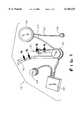
- FIG. 1is an exploded isometric view of the implantable subsystems of the present invention
- FIG. 2is an exploded isometric view of the external subsystems of the present invention.
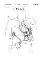
- FIG. 3is a schematic showing general placement of the implantable subsystem within a human body
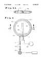
- FIG. 4is a fragmentary exploded front elevational view, partially in cross-section, of the compliance chamber, subcutaneous port, and conduit means connecting the same;
- FIG. 4Ais a sectional view taken along the line 4A--4A of FIG. 4;
- FIG. 5is a fragmentary side elevational view, in section, taken along the line 5--5 of FIG. 1 and showing the connection of the hard polymer tubing and the graft tubing to form the outlet cannula, with portions thereof being removed to reveal details of internal construction;
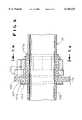
- FIG. 6is a fragmentary side elevational view, in section, taken along the line 6--6 of FIG. 1 and showing the means for securing together the apical cuff and the tube entering the left ventricle;
- FIG. 6Ais an exploded side elevational view thereof, in section
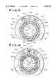
- FIG. 7is a sectional view of the securing means in an open orientation, taken along the line 7--7 of FIG. 6;
- FIG. 8is a sectional view thereof in a closed orientation, taken along the line 8--8 of FIG. 6.
- FIG. 1therein illustrated are the various implantable subsystems of an LVAD according to the present invention, generally designated by the reference numeral 10, as follows:
- the blood pump subsystem 20receives and pumps blood from the heart chamber (e.g., the left ventricle) to the aorta via two cannulae (the below-mentioned inlet and outlet cannulae 30, 32) and one-way valves. It acts in parallel and asynchronously to the heart chamber (e.g., the left ventricle).
- the controller subsystem 22receives power via an induction process and rectifies the power for use in controlling the pump motor 20. It transmits and receives telemetry through an enclosure, dispenses power rectified from an external source, charges internal battery power, and transmits data about the internal battery state via an inductive coil path.
- the compliance chamber 24 and subcutaneous infusion port 26 subsystemcompensates for gas volume displacement produced by blood-sac volume changes and gas volume losses due to diffusion through the blood-sac in the blood pump subsystem 20.
- the internal coil subsystem 28receives power and broadcasts data about the internal battery state of the controller 22.
- the inlet cannula subsystem 30provides a transport path of blood from the heart chamber access point (e.g., the left ventricular apex) to the blood pump subsystem 20.
- the heart chamber access pointe.g., the left ventricular apex
- the outlet cannula subsystem 32provides a transport path of blood from the blood pump subsystem 20 to the ascending aorta.
- FIG. 2therein illustrated are the various external subsystems (that is, devices maintained outside of the patient's body) which are used in connection with the implantable subsystems as follows:
- the power transmitter 40(with external coil 42) subsystem converts the DC power to AC power and transmits the AC power to the implanted controller subsystem 22 via an inductive coil link 42. It also receives data from the controller subsystem 22 about the internal battery state and monitors power performance.
- the power pack subsystem 44sends DC power to the power transmitter subsystem 40, using battery packs 46 or an external source, and acts as a performance alarm center.
- the power pack subsystem 44may be externally powered either through a lightweight portable power supply which converts AC power to DC power for the power pack, or a lightweight transportation supply which converts DC vehicular power to appropriate DC power for the power pack.
- the battery charger subsystem 48charges, refreshes, and tests the removable power pack subsystem batteries 46 on a pass/fail basis.
- an external system monitor subsystem(not shown) is preferably used to display all broadcast telemetry information from the implanted controller subsystem and to initiate reprogramming of certain implanted controller subsystem settings.
- FIG. 3therein illustrated is a sketch showing generally, for ease of visualization, the preferred locations of the various implanted LVAD components 10. Clearly, the various components may be relocated from the illustrated sites and still operate according to the principles of the present invention.
- the external power pack subsystem 44supplies DC power to the external power transmitter 40, where it is converted to an AC voltage.
- the external power pack subsystem 44preferably includes at least a pair of rechargeable batteries 46.
- the external power transmitter subsystem 40drives an external ring-shaped external coil 42 that is placed on a patient's skin surface, directly over the implanted internal coil 28. AC power is transmitted through the intact skin from the external coil 42 to the internal coil 28 through induction. From the internal coil 28, power is conducted to the implanted controller 22, where it is rectified to a DC voltage and used to power the implanted controller 22 and to drive the implanted blood pump 20.
- the implanted blood pump 20is a brushless DC motor that drives a pusher-plate in a reciprocating fashion to compress a smooth-walled blood-sac and produce pulsatile flow.
- the blood-sachas two ports: an inlet and an outlet.
- One-way, monostrut disk valvescontrol the direction of flow through the ports.
- the pusher-platecompresses the blood-sac and forces blood through the outlet cannula 32 (via the one-way outlet valve), and into the aorta.
- the pusher-plateWhen the pusher-plate is in the diastole position, the pusher-plate is completely retracted, allowing blood to flow from the heart chamber (e.g., the left-ventricular apex) through the inlet cannula 30 (via the one-way inlet valve), and into the blood-sac.
- the heart chambere.g., the left-ventricular apex
- the inlet cannula 30via the one-way inlet valve
- Compliance or volume compensator chambersare old in the art and are used to provide gas to pump 20 via conduit 54 during the emptying (compression) of the blood-sac or systolic stroke of a pump cycle and to absorb gas from the pump 20 via conduit 54 during the filling of the blood-sac or diastolic stroke of a pump cycle.
- compliance chamber 24allows gas to be shuttled to and from the pump 20 as differential pressures are created by the pump's mechanical motion.
- An implanted infusion port 26is typically connected, via conduit 60, to the compliance chamber 24 to facilitate gas replenishment when necessary.
- the gas which enters the compliance chamber 24 from pump 20may contain dissolved or entrained moisture or gases which condense within the chamber due to a temperature differential and may thereafter flow back to the pump 20, thereby interfering with efficient operation of both the compliance chamber 24 and the pump 20.
- the implanted controller 22contains the electronics necessary to perform the control functions of the implanted blood pump 20. It also contains rechargeable batteries (not shown) as a back-up to the external power supply 44 if the latter were removed from the patient. These rechargeable batteries will supply power to the LVAD for a period of time so that the patient can attend to personal needs for which they choose to be untethered to the external power supply 44. The batteries can rapidly be recharged after the external power supply is coupled once again.
- Software algorithmsare stored in the implanted controller 22. These algorithms adjust the implanted blood pump's performance contingent upon feedback about the pump's motor position and information about the internal voltage supply of the implanted controller. This feedback provides an inference as to the pump's filling rate, which is in turn an indication of the patient's cardiac output needs.
- the algorithmswill attempt to pump enough blood so that a large percentage of the pump's "blood-sac" is utilized every stroke.
- the algorithmswill manage other tasks such as charging the internal batteries, and providing telemetry communication to the outside world (i.e., an external system monitor).
- LVAD system monitor subsystemAnother important element of the LVAD system is an external system monitor subsystem. This is used for telemetry communication with the implanted controller and displays all broadcast telemetry information from the controller subsystem and initiates reprogramming of certain controller settings. This monitor is necessary to evaluate the LVAD function in vivo. It can also be used to modify device parameters or download a program change if it is needed.
- Biocompatibility requirementsinclude avoidance of hemolysis, thrombosis, or damage to tissues surrounding the device.
- the systemis designed to operate with the patient's skin fully intact.
- device failureshould not have sequelae that interfere with remnant native heart function, cause catastrophic loss of blood, or otherwise prevent emergent salvage of the patient. Since successful emergency care of a patient with a non-functioning assist pump and minimal native heart function is seen as possible, device failure should not result in consequential damage (e.g., tissue damage due to overheating) that would prevent or complicate the patient's eventual recovery.
- consequential damagee.g., tissue damage due to overheating
- the LVADincludes both implantable subsystems 10 and external subsystems 38, the entire LVAD is considered to be essentially implantable as the skin is not pierced for connection between the implantable and external subsystems, thus minimizing the chance for infection to pass through the skin.
- the implantable LVAD subsystems 10solve the previously enumerated deficiencies of the known implantable subsystems of an LVAD as described hereinafter.
- the first problemarises because the main stream of gas G passing through the blood pump 20 typically carries with it entrained or dissolved liquids, such as blood or water, and/or condensable gases.
- This entrained or dissolved liquid and/or condensable gasmay separate from the main stream of gas G within the compliance chamber 24 and, under the influence of gravity, accumulate at the bottom of the compliance chamber 24.
- the collected liquid L at the bottom of the compliance chamber 24interferes with the proper functioning of the compliance chamber by limiting its contractibility and consuming volumetric space intended for the gas.
- the compliance chamber 24forms a reservoir 50 for liquid L extending from adjacent the bottom of the compliance chamber upwardly towards the top of the compliance chamber.
- the compliance chamber 24also forms a chamber 52 for gas G disposed above the liquid reservoir 50 and extending upwardly to the top of the compliance chamber.
- the gas chamber 52extends downwardly from the top of the compliance chamber towards the liquid reservoir 50.
- the gas chamber 52is in gaseous communication with the implanted blood pump subsystem 20 via a tube 54 connecting the blood pump subsystem 20 and the compliance chamber 24.
- the compliance chamber 24receives the main stream of gas G from, and discharges the main stream of gas G to, the pump 20 via tube 54, the main stream of gas G typically including at least a small amount of entrained or dissolved liquid and/or condensable gas.
- the tube 54extends upwardly into the gas chamber 52, well above the liquid reservoir 50.
- the upper end of the tube 54directly connects the pump 20 and the gas chamber 52 above the top of the liquid reservoir 50.
- the upper end of the tube 54acts as a weir 56 having one end passing upwardly through the liquid reservoir 50 and in gaseous communication with the gas chamber 52, and the other end in gaseous communication with the pump 20.
- the weir 56is illustrated as being a portion of the tube 54, clearly the weir 56 may be a separate structural element, acting cooperatively with the tube 54, to place the pump 20 and gas chamber 52 in gaseous communication.
- gaseous communicationincludes the presence of entrained or dissolved liquid within the gas stream.
- the tube 54may directly enter the compliance chamber 24 within the gas chamber 52 (that is, without first passing through the liquid reservoir 50), preferably adjacent the top of the gas chamber 52. In this instance, no weir 56 is required.
- a conduit 60has one end extending into the liquid reservoir 50 (preferably at or adjacent the bottom thereof) and the other end secured to the subcutaneous port 26 for liquid and gaseous communication between the liquid reservoir 50 and the port 26.
- the conduit 60connects the port 26 and the bottom (or a level adjacent the bottom) of the liquid reservoir 50.
- top of the liquid reservoir 50 and the bottom of the gas chamber 52are the same and may be disposed at various heights along the longitudinal axis of the compliance chamber 24 so long as the gas G entering and leaving the gas chamber 52 via the weir 56 does so without having to pass directly through the liquid reservoir 50 (that is, the weir 56 protects it from the liquid L in the liquid reservoir 50).
- the subcutaneous port 26is, in certain respects, similar to the conventional "infusion port" used in an LVAD in order to enable air or like gas to be introduced into or removed from the LVAD system to compensate for air or other gas losses or gains through the blood-sac in the blood pump 20.
- the subcutaneous port 26is used not simply to introduce or remove gas G into or from the implanted LVAD subsystems (and in particular, compliance chamber 24), but also to drain the liquid L from the liquid reservoir 50.
- the liquid reservoir 50may be drained entirely of liquid L by a physician using an empty hypodermic needle 59 to establish communication between such needle and the liquid reservoir 50 via the conduit 60.
- the compliance chamber 24is oriented so that the conduit 60 communicates with the liquid L of the liquid reservoir 50 at the very bottom thereof so as to enable a complete drainage of the reservoir 50 by the physician, although the conduit 60 may alternatively be adjacent the bottom of the liquid reservoir 50 (i.e., slightly off to one side), although this may result in some of the liquid L remaining in the liquid reservoir 50.
- the accumulating liquid L in the liquid reservoir 50may or may not be allowed to enter the conduit 60.
- the liquid Lwill tend to enter the conduit 60 and eventually fill it, so long as the height of the liquid L is above the distal end of the conduit 60.
- the conduit 60may be designed so that the column of air trapped within the second conduit 60 resists entry of the liquid L into conduit 60 until the septum of infusion port 26 is penetrated by a physician's hypodermic needle 59 and the column of air aspirated.
- the compliance chamber 24/subcutaneous port 26 subassembly of the present inventionenables the physician to first substantially drain the liquid L in liquid reservoir 50 from the compliance chamber 24.
- the conduit 60communicates directly with the gas chamber 52 and can be used to introduce make-up or remove excess gas as necessary, without having the gas pass directly through the liquid reservoir 50 in intimate contact with any liquid L therein.
- the make-up gas introduced into compliance chamber 24 according to the present inventionis dry relative to the make-up gas introduced by a conventional infusion port through the accumulated liquid.
- the end of the tube 54 (or weir 56) extending into the gas chamber 52contains a plurality of apertures along its circumferential surface within gas chamber 52 so that gas G may be introduced from the tube 54 directly into the gas chamber 52 of the compliance chamber 24 faster than would be the case if the tube 54 (or weir 56) had only a single opening at the tip thereof.
- the placement of such side aperturesmust always be such that the liquid L of liquid reservoir 50 cannot enter therethrough.
- the present inventionfurther addresses the second problem noted with the implantable components of LVAD's, namely, the difficulty in securing together in an outlet cannula, the hard polymer tubing (adjacent pump 20) and the graft tubing (adjacent the aorta).
- FIG. 5therein illustrated is an outlet cannula 30 according to the present invention.
- the distal end 70 of the hard polymer tubing 72 and the proximal end 74 of the graft tubing 76are secured together by a snap-fit connector, generally designated 80, formed of two connector components 82, 84.
- the proximal connector component 82is secured or bonded to the distal end 70 of the hard polymer tubing 72, extends circumferentially thereabout, and is at least strongly resiliently flexible. While the proximal component 82 is secured to the hard polymer tubing 72 adjacent its distal end 70, the distal lip 82A of proximal component 82 is somewhat flexible and may be resiliently bent outwardly from the distal end 70 so that the distal lip 82A is maintained adjacent the distal end 70 only by the resilient nature of the material, and not by any bonding mechanism.
- the distal connector component 84is secured or bonded to the proximal end 74 of the graft tubing 76, extends circumferentially thereabout, and is relatively rigid.
- the distal component 84defines an outwardly and distally sloped lug 84A which cams the distal lip 82A of the proximal component 82 away from the hard polymer tubing end 70 and allows the distal lip 82A to travel over the lug 84A and then resiliently return (or "snap") to its original orientation, with a flange on the distal end of one component (as shown, distal component 82) extending into a recess within the proximal end of the other component (as shown, proximal component 84) to preclude further relative axial motion.
- the distal end 70 of the hard polymer tubing 72 and the proximal end 78 of the graft tubing 76are secured together by axial movement of components 82, 84 of the snap-fit connector 80, without any relative rotation of the connector components 82, 84 being required.
- the connector components 82, 84are preferably formed of titanium because titanium has acceptable biological properties and either rigidity or high resiliency, depending on its configuration and dimensions.
- the distal connector component 84additionally defines a proximally projecting lug 84B around which the strain relief material 86 discussed below extends (both inwardly and outwardly thereof), and then the proximal end 74 of the graft tubing 76 extends around the strain relief material 86 about the lug 84B.
- a strain-relief material 86is disposed substantially between the proximal end 74 of the graft tubing 76 and the much harder elements of the connector 80, and in particular the distal connector component 84.
- the strain relief material 86follows the path of the graft tubing 76 to preclude any contact of the distal connector component 84 directly with the graft tubing 76, except possibly beyond distal end 78 of the graft tubing 76. This reduces abrasion of the susceptible graft tubing 76 by the distal connector component 84.
- the proximal end 74 of the graft tubing 76is essentially protected from both components 82, 84 of the connector 80.
- the strain relief material 86may simply be a length of hard polymer tubing, similar to tubing 72 but preferably more flexible and elastic.
- the strain relief material 86may extend distally of the connector 80 an appreciable length, although such an extension of the strain relief material 86 is not necessary beyond the point required to ensure that there is no contact between the distal connector component 84 and the graft tubing 76.
- the inner surface of the graft tubing 76 and the inner surface of the hard polymer tubing 72are preferably longitudinally aligned so that the relatively smooth transition from one to the other (and in particular, from the hard polymer tubing 72 to the graft tubing 76) does not create a flow-limiting obstruction.
- the connector 80further assists in maintaining patency (the open status) of both the tubings 72, 76.
- the present inventionfurther addresses the third problem, namely, the difficulty in securing together the distal end of a tube (for example, a titanium tube entering the heart at a proximal end), and the distal end of a sewable flexible apical cuff (disposed adjacent the proximal end of the inlet cannula 30 to facilitate attachment of the cuff to the heart (e.g., the myocardium) via conventional surgical sewing).
- the problem hereis the complexity and unreliability of the means conventionally used for securing together the apical cuff and the tube.
- a sewable flexible apical cuffgenerally designated 110, adapted to be sewn to a heart, e.g., the myocardium (not shown), and a rigid tube 108 adapted to enter the heart chamber (not shown), as well as means, generally designated 120, for securing together the cuff 110 and tube 108.
- the structural element 107 of the cuff 110is preferably hat-shaped, with the brim 107a of the hat being disposed on the distal end.
- the brim or distal end 107a of the structural element 107is surrounded on the distal side by a velour ring 104 and on the proximal side by a felt ring 106, and bonded to both rings 104, 106.
- the velour ring 104 and the felt ring 106enable ingrowth of the cells of the heart into the velour and felt, thereby to integrate the cuff and the myocardium.
- the felt ring 106strengthens the distal surface of the cuff brim 107a, provides a means to sew and secure the cuff 110 to the heart, and further protects the cuff brim 107a from the securing means 120.
- the securing means 120includes a collet, generally designated 121, defining multiple radially compressible circumferentially curved fingers 122 (six being shown) and a collar, generally designated 124, for radially inwardly moving (i.e., compressing) the collet fingers 122 to crimp a length 107b of the cuff structural element 107 (distal to the cuff brim 107a and intermediate the collet 121 and the tube 108) onto the tube 108 as the collar 124 is rotated relative to the collet 121 and its fingers 122 from an initial relative orientation, as illustrated in FIG. 7, to a final relative orientation, as illustrated in FIG. 8.
- the outer surface of the fingers 122 of resilient plastic collet 121defines circumferentially spaced flats 126
- the inner surface of the rigid metal collar 124defines circumferentially spaced flats 128 (e.g., the inner surface of the collar 124 defines a regular polygon (a hexagon being shown)).
- the fingers 122 and the collar 124have an initial relative orientation (see FIG. 7) such that the finger flats 126 are radially aligned with the collar flats 128, and a final relative orientation (see FIG.
- the collar 124is at least partially rotatable relative to the collet 121 (and in particular the collet fingers 122), and the entire collet 121 is rotatable relative to the tube 108.
- alternative collar/collet mechanismsmay be used to move the collet fingers inwardly in order to clamp the apical cuff onto the tube.
- the outer surface of the collet fingersmay define outwardly extending lobes
- the inner surface of the collarmay define circumferentially spaced recesses for receiving the lobes while the collet and collar are in an initial relative orientation.
- the portions of the inner surface of the collar intermediate the recesseswill press against the finger lobes and thus displace the fingers inwardly toward the tube.
- Preferably meansare provided to lock the collar 124 in its final relative orientation relative to the collet 121, thereby to preclude release of the apical cuff 110 from the securing means 120 due to accidental rotation of the collar 124 relative to the collet 121.
- a collar pin 130may be movable from an initial relative orientation deep within a collet slot 132 into a collet channel 134 when the collet 121 and collar 124 are in the final relative orientation, the slot 132 closing thereafter to prevent accidental return of the collar pin 130 into the slot 132.
- the collet 121may be provided with a pin 136 to facilitate relative movement of the collet 121 and the collar 124 by squeezing together of the two pins 130, 136.
- the means 120 for securing the cuff and the tube togetherdoes not require substantial relative rotation of the tube and the cuff.
- the required relative rotation of the collar 124 and the collet 121is relatively minimal, being equal to 180° divided by the number of collet fingers 122 or collar flats 128 (as illustrated, only 30°).
- the securing means 120thus easily and economically secures together the cuff and the tube in a reliable manner.
- the present inventionprovides an improved, and preferably implantable, LVAD which is simple and economical to assemble, implant and maintain.
- the LVADenables accumulated liquid within the compliance chamber to be withdrawn through a subcutaneous port, thereby increasing the efficiency of the blood pump/compliance chamber subassembly. It may also include an easy-to-operate and reliable means for connecting together the hard polymer tubing and the graft tubing of the outlet cannula without abrasion of the graft tubing by the connector means. It may further include an easy-to-operate and reliable means for securing together the apical cuff and the tube entering the heart chamber.
Landscapes
- Health & Medical Sciences (AREA)
- Heart & Thoracic Surgery (AREA)
- Engineering & Computer Science (AREA)
- Cardiology (AREA)
- Veterinary Medicine (AREA)
- Anesthesiology (AREA)
- Biomedical Technology (AREA)
- Hematology (AREA)
- Life Sciences & Earth Sciences (AREA)
- Animal Behavior & Ethology (AREA)
- General Health & Medical Sciences (AREA)
- Public Health (AREA)
- Mechanical Engineering (AREA)
- Vascular Medicine (AREA)
- Computer Networks & Wireless Communication (AREA)
- External Artificial Organs (AREA)
Abstract
Description
Claims (17)
Priority Applications (8)
| Application Number | Priority Date | Filing Date | Title |
|---|---|---|---|
| US09/325,334US6146325A (en) | 1999-06-03 | 1999-06-03 | Ventricular assist device |
| PCT/US2000/011191WO2000074747A1 (en) | 1999-06-03 | 2000-04-26 | Ventricular assist device |
| EP00928406AEP1191957A4 (en) | 1999-06-03 | 2000-04-26 | VENTRIKELHILFSVORRICHTUNG |
| AU46654/00AAU4665400A (en) | 1999-06-03 | 2000-04-26 | Ventricular assist device |
| JP2001501279AJP2003501154A (en) | 1999-06-03 | 2000-04-26 | Ventricular assist device |
| CA002373956ACA2373956A1 (en) | 1999-06-03 | 2000-04-26 | Ventricular assist device |
| MXPA01012350AMXPA01012350A (en) | 1999-06-03 | 2000-04-26 | Ventricular assist device. |
| ZA200109828AZA200109828B (en) | 1999-06-03 | 2001-11-29 | Ventricular assist device. |
Applications Claiming Priority (1)
| Application Number | Priority Date | Filing Date | Title |
|---|---|---|---|
| US09/325,334US6146325A (en) | 1999-06-03 | 1999-06-03 | Ventricular assist device |
Publications (1)
| Publication Number | Publication Date |
|---|---|
| US6146325Atrue US6146325A (en) | 2000-11-14 |
Family
ID=23267454
Family Applications (1)
| Application Number | Title | Priority Date | Filing Date |
|---|---|---|---|
| US09/325,334Expired - LifetimeUS6146325A (en) | 1999-06-03 | 1999-06-03 | Ventricular assist device |
Country Status (8)
| Country | Link |
|---|---|
| US (1) | US6146325A (en) |
| EP (1) | EP1191957A4 (en) |
| JP (1) | JP2003501154A (en) |
| AU (1) | AU4665400A (en) |
| CA (1) | CA2373956A1 (en) |
| MX (1) | MXPA01012350A (en) |
| WO (1) | WO2000074747A1 (en) |
| ZA (1) | ZA200109828B (en) |
Cited By (117)
| Publication number | Priority date | Publication date | Assignee | Title |
|---|---|---|---|---|
| US20020051550A1 (en)* | 2000-08-25 | 2002-05-02 | Hans Leysieffer | Implantable hermetically sealed housing for an implantable medical device and process for producing the same |
| US6402781B1 (en) | 2000-01-31 | 2002-06-11 | Mitralife | Percutaneous mitral annuloplasty and cardiac reinforcement |
| US20030023131A1 (en)* | 2001-06-06 | 2003-01-30 | Antaki James F. | Apparatus and method for reducing heart pump backflow |
| US20030023255A1 (en)* | 2001-06-29 | 2003-01-30 | Miles Scott D. | Cannulation apparatus and method |
| US6537268B1 (en)* | 1998-06-18 | 2003-03-25 | Medtronic Minimed, Inc. | Medical infusion device with a source of controlled compliance |
| US20030130668A1 (en)* | 2001-06-29 | 2003-07-10 | Nieman Timothy R. | Endoscopic cannulation apparatus and method |
| US20030187481A1 (en)* | 2002-03-16 | 2003-10-02 | Chang Sheldon S. | Device for cardiac restoration |
| US20030233144A1 (en)* | 2002-06-13 | 2003-12-18 | Antaki James F. | Low profile inlet for an implantable blood pump |
| US20040147802A1 (en)* | 2001-05-21 | 2004-07-29 | Woodard John Campbell | Staged implantation of ventricular assist devices |
| US20040193004A1 (en)* | 2003-03-28 | 2004-09-30 | Terumo Corporation | Method and apparatus for adjusting a length of the inflow conduit on a ventricular assist device |
| US6810882B2 (en) | 2001-01-30 | 2004-11-02 | Ev3 Santa Rosa, Inc. | Transluminal mitral annuloplasty |
| US20040242954A1 (en)* | 2003-05-30 | 2004-12-02 | Moises Calderon | Universal pneumatic ventricular assist device |
| US20050033107A1 (en)* | 2003-07-31 | 2005-02-10 | Terumo Corporation | Adjustable coupling mechanism for the conduit on a ventricular assist device |
| US20050192559A1 (en)* | 2004-03-01 | 2005-09-01 | Michels Lester D. | Delivery system and method |
| US20050251187A1 (en)* | 2004-03-23 | 2005-11-10 | Correx, Inc. | Apparatus and method for connecting a conduit to a hollow organ |
| US6989028B2 (en) | 2000-01-31 | 2006-01-24 | Edwards Lifesciences Ag | Medical system and method for remodeling an extravascular tissue structure |
| US7011682B2 (en) | 2000-01-31 | 2006-03-14 | Edwards Lifesciences Ag | Methods and apparatus for remodeling an extravascular tissue structure |
| US20060161193A1 (en)* | 2004-12-15 | 2006-07-20 | Correx, Inc. | Apparatus and method for connecting a conduit to a hollow vessel |
| US20070066943A1 (en)* | 2005-09-21 | 2007-03-22 | Abiomed, Inc. | Cannula systems and methods of use |
| US20070088375A1 (en)* | 2004-03-23 | 2007-04-19 | Correx, Inc. | Apparatus and method for forming a hole in a hollow organ |
| US20070112422A1 (en)* | 2005-11-16 | 2007-05-17 | Mark Dehdashtian | Transapical heart valve delivery system and method |
| US20070265643A1 (en)* | 2004-03-23 | 2007-11-15 | Beane Richard M | Apparatus and method for suturelessly connecting a conduit to a hollow organ |
| US20080015403A1 (en)* | 2006-07-12 | 2008-01-17 | Allegheny-Singer Research Institute | Apical torsion device for cardiac assist |
| US20080300447A1 (en)* | 2006-01-30 | 2008-12-04 | Pong-Jeu Lu | Dual-Pulsation Bi-Ventricular Assist Device |
| US7473266B2 (en) | 2003-03-14 | 2009-01-06 | Nmt Medical, Inc. | Collet-based delivery system |
| US20090082778A1 (en)* | 2007-09-25 | 2009-03-26 | Correx, Inc. | Applicator, assembly, and method for connecting an inlet conduit to a hollow organ |
| US7510576B2 (en) | 2001-01-30 | 2009-03-31 | Edwards Lifesciences Ag | Transluminal mitral annuloplasty |
| US20100256441A1 (en)* | 2008-12-31 | 2010-10-07 | Pong-Jeu Lu | Cardiac Compression System |
| US20110015728A1 (en)* | 2009-07-14 | 2011-01-20 | Edwards Lifesciences Corporation | Transapical delivery system for heart valves |
| US20110118833A1 (en)* | 2009-11-15 | 2011-05-19 | Thoratec Corporation | Attachment device and method |
| US20110118829A1 (en)* | 2009-11-15 | 2011-05-19 | Thoratec Corporation | Attachment device and method |
| US20110125256A1 (en)* | 2009-11-15 | 2011-05-26 | Thoratec Corporation | Slitting Tool |
| US20110160850A1 (en)* | 2009-12-30 | 2011-06-30 | Thoratec Corporation | Blood Pump System With Mounting Cuff |
| US20110160516A1 (en)* | 2009-12-30 | 2011-06-30 | Thoratec Corporation | Mobility-Enhancing Blood Pump System |
| US7993260B2 (en) | 1997-10-09 | 2011-08-09 | Thoratec Corporation | Implantable heart assist system and method of applying same |
| US20110251597A1 (en)* | 2010-04-08 | 2011-10-13 | Warsaw Orthopedic, Inc. | Neural-monitoring enabled sleeves for surgical instruments |
| WO2012119073A1 (en)* | 2011-03-02 | 2012-09-07 | Thoratec Corporation | Ventricular cuff |
| EP2530789A3 (en)* | 2009-12-30 | 2013-02-27 | Thoratec Corporation | Mobility-enhancing blood pump system |
| US20130096364A1 (en)* | 2011-10-13 | 2013-04-18 | Steven H. Reichenbach | Pump and method for mixed flow blood pumping |
| WO2013103480A1 (en)* | 2012-01-05 | 2013-07-11 | Terumo Kabushiki Kaisha | Apical ring for ventricular assist device |
| US20130196301A1 (en)* | 2012-01-31 | 2013-08-01 | David Jeffrey Carson | Cardiac Simulation Device |
| WO2013138451A1 (en)* | 2012-03-13 | 2013-09-19 | Sunshine Heart Company Pty Ltd | Methods, systems, and devices relating to wireless power transfer |
| US8702583B2 (en) | 2003-11-11 | 2014-04-22 | Sunshine Heart Company Pty, Ltd. | Actuator for a heart assist device |
| US8728012B2 (en) | 2008-12-19 | 2014-05-20 | St. Jude Medical, Inc. | Apparatus and method for measuring blood vessels |
| US8771164B2 (en) | 2008-03-28 | 2014-07-08 | Vitalmex Internacional S.A. De C.V. | Fluid pumping ventricular assist device and components with static seal |
| US8777833B2 (en) | 2002-11-15 | 2014-07-15 | Sunshine Heart Company Pty. Ltd. | Heart assist device utilising aortic deformation |
| US8821365B2 (en) | 2009-07-29 | 2014-09-02 | Thoratec Corporation | Rotation drive device and centrifugal pump apparatus using the same |
| US8827661B2 (en) | 2008-06-23 | 2014-09-09 | Thoratec Corporation | Blood pump apparatus |
| WO2014149892A1 (en)* | 2013-03-15 | 2014-09-25 | Thoratec Corporation | Ventricular cuff |
| US20140316426A1 (en)* | 2011-05-16 | 2014-10-23 | Berlin Heart Gmbh | Connection system for the detachable fixation of a hollow cylindrical component at a recess |
| US8905961B2 (en) | 2008-12-19 | 2014-12-09 | St. Jude Medical, Inc. | Systems, apparatuses, and methods for cardiovascular conduits and connectors |
| US9042979B2 (en) | 2010-04-02 | 2015-05-26 | Sunshine Heart Company Pty Limited | Combination heart assist systems, methods, and devices |
| US9067005B2 (en) | 2008-12-08 | 2015-06-30 | Thoratec Corporation | Centrifugal pump apparatus |
| US9068572B2 (en) | 2010-07-12 | 2015-06-30 | Thoratec Corporation | Centrifugal pump apparatus |
| US9119908B2 (en) | 2003-10-31 | 2015-09-01 | Sunshine Heart Company Pty. Ltd. | Synchronization control system |
| US9132215B2 (en) | 2010-02-16 | 2015-09-15 | Thoratee Corporation | Centrifugal pump apparatus |
| US9133854B2 (en) | 2010-03-26 | 2015-09-15 | Thoratec Corporation | Centrifugal blood pump device |
| US9138228B2 (en) | 2004-08-11 | 2015-09-22 | Emory University | Vascular conduit device and system for implanting |
| WO2015109328A3 (en)* | 2014-01-17 | 2015-11-12 | Correx, Inc. | Apparatus and method for forming a hole in a hollow organ, connecting a conduit to the hollow organ and connecting a left ventricular assist device (lvad) to the hollow organ |
| US9199019B2 (en) | 2012-08-31 | 2015-12-01 | Thoratec Corporation | Ventricular cuff |
| WO2015195660A1 (en)* | 2014-06-17 | 2015-12-23 | Heartware, Inc. | Connector ring clamp and associated methods of use |
| US9308015B2 (en) | 2007-04-24 | 2016-04-12 | Emory University | Conduit device and system for implanting a conduit device in a tissue wall |
| US9320875B2 (en) | 2011-02-01 | 2016-04-26 | Emory University | Systems for implanting and using a conduit within a tissue wall |
| US9366261B2 (en) | 2012-01-18 | 2016-06-14 | Thoratec Corporation | Centrifugal pump device |
| US9371826B2 (en) | 2013-01-24 | 2016-06-21 | Thoratec Corporation | Impeller position compensation using field oriented control |
| US9382908B2 (en) | 2010-09-14 | 2016-07-05 | Thoratec Corporation | Centrifugal pump apparatus |
| US9381285B2 (en) | 2009-03-05 | 2016-07-05 | Thoratec Corporation | Centrifugal pump apparatus |
| US9381082B2 (en) | 2011-04-22 | 2016-07-05 | Edwards Lifesciences Corporation | Devices, systems and methods for accurate positioning of a prosthetic valve |
| US9410549B2 (en) | 2009-03-06 | 2016-08-09 | Thoratec Corporation | Centrifugal pump apparatus |
| US9433717B2 (en) | 2010-09-24 | 2016-09-06 | Thoratec Corporation | Generating artificial pulse |
| US9492599B2 (en) | 2012-08-31 | 2016-11-15 | Thoratec Corporation | Hall sensor mounting in an implantable blood pump |
| US9532773B2 (en) | 2011-01-28 | 2017-01-03 | Apica Cardiovascular Limited | Systems for sealing a tissue wall puncture |
| US9556873B2 (en) | 2013-02-27 | 2017-01-31 | Tc1 Llc | Startup sequence for centrifugal pump with levitated impeller |
| US9566146B2 (en) | 2008-12-19 | 2017-02-14 | St. Jude Medical, Inc. | Cardiovascular valve and valve housing apparatuses and systems |
| US9623161B2 (en) | 2014-08-26 | 2017-04-18 | Tc1 Llc | Blood pump and method of suction detection |
| US9629948B2 (en) | 2014-04-15 | 2017-04-25 | Tc1 Llc | Methods for upgrading ventricle assist devices |
| US9656010B2 (en) | 2010-07-22 | 2017-05-23 | Tc1 Llc | Controlling implanted blood pumps |
| US9675741B2 (en) | 2010-08-20 | 2017-06-13 | Tc1 Llc | Implantable blood pump |
| US9687345B2 (en) | 2014-05-29 | 2017-06-27 | Edwards Lifesciences Cardiaq Llc | Prosthesis, delivery device and methods of use |
| US9694123B2 (en) | 2014-04-15 | 2017-07-04 | Tc1 Llc | Methods and systems for controlling a blood pump |
| US9713663B2 (en) | 2013-04-30 | 2017-07-25 | Tc1 Llc | Cardiac pump with speed adapted for ventricle unloading |
| US9731058B2 (en) | 2012-08-31 | 2017-08-15 | Tc1 Llc | Start-up algorithm for an implantable blood pump |
| US9744280B2 (en) | 2014-04-15 | 2017-08-29 | Tc1 Llc | Methods for LVAD operation during communication losses |
| CN107206140A (en)* | 2014-12-10 | 2017-09-26 | 心脏器械股份有限公司 | Heart pump implant device and method |
| US9775936B2 (en) | 2010-10-18 | 2017-10-03 | WorldHeart Corp. | Blood pump with separate mixed-flow and axial-flow impeller stages, components therefor and related methods |
| US9786150B2 (en) | 2014-04-15 | 2017-10-10 | Tci Llc | Methods and systems for providing battery feedback to patient |
| US9782527B2 (en) | 2009-05-27 | 2017-10-10 | Tc1 Llc | Monitoring of redundant conductors |
| US9839733B2 (en) | 2010-06-22 | 2017-12-12 | Tc1 Llc | Apparatus and method for modifying pressure-flow characteristics of a pump |
| US9849224B2 (en) | 2014-04-15 | 2017-12-26 | Tc1 Llc | Ventricular assist devices |
| US9850906B2 (en) | 2011-03-28 | 2017-12-26 | Tc1 Llc | Rotation drive device and centrifugal pump apparatus employing same |
| US9981076B2 (en) | 2012-03-02 | 2018-05-29 | Tc1 Llc | Ventricular cuff |
| US10028741B2 (en) | 2013-01-25 | 2018-07-24 | Apica Cardiovascular Limited | Systems and methods for percutaneous access, stabilization and closure of organs |
| US10052420B2 (en) | 2013-04-30 | 2018-08-21 | Tc1 Llc | Heart beat identification and pump speed synchronization |
| US10111994B2 (en) | 2013-05-14 | 2018-10-30 | Heartware, Inc. | Blood pump with separate mixed-flow and axial-flow impeller stages and multi-stage stators |
| US10117983B2 (en) | 2015-11-16 | 2018-11-06 | Tc1 Llc | Pressure/flow characteristic modification of a centrifugal pump in a ventricular assist device |
| US10149757B2 (en) | 2013-03-15 | 2018-12-11 | Edwards Lifesciences Corporation | System and method for transaortic delivery of a prosthetic heart valve |
| US10166318B2 (en) | 2015-02-12 | 2019-01-01 | Tc1 Llc | System and method for controlling the position of a levitated rotor |
| US10229615B2 (en) | 2012-01-31 | 2019-03-12 | Vascular Simulations Inc. | Cardiac simulation device |
| US10245361B2 (en) | 2015-02-13 | 2019-04-02 | Tc1 Llc | Impeller suspension mechanism for heart pump |
| US10335527B2 (en) | 2017-11-08 | 2019-07-02 | The Regents Of The University Of Colorado, A Body Corporate | Ventricular assist assembly, system, and method |
| RU2696685C1 (en)* | 2018-09-18 | 2019-08-05 | Федеральное государственное автономное образовательное учреждение высшего образования "Национальный исследовательский университет "Московский институт электронной техники" | Apparatus for connecting an auxiliary circulation pump to the human ventricle |
| US10371152B2 (en) | 2015-02-12 | 2019-08-06 | Tc1 Llc | Alternating pump gaps |
| US10485909B2 (en) | 2014-10-31 | 2019-11-26 | Thoratec Corporation | Apical connectors and instruments for use in a heart wall |
| US10506935B2 (en) | 2015-02-11 | 2019-12-17 | Tc1 Llc | Heart beat identification and pump speed synchronization |
| US10518012B2 (en) | 2013-03-15 | 2019-12-31 | Apk Advanced Medical Technologies, Inc. | Devices, systems, and methods for implanting and using a connector in a tissue wall |
| US10660998B2 (en) | 2016-08-12 | 2020-05-26 | Tci Llc | Devices and methods for monitoring bearing and seal performance |
| US10724534B2 (en) | 2014-11-26 | 2020-07-28 | Tc1 Llc | Pump and method for mixed flow blood pumping |
| US10729834B2 (en)* | 2014-12-19 | 2020-08-04 | Yale University | Heart failure recovery device and method of treatment |
| US10857273B2 (en) | 2016-07-21 | 2020-12-08 | Tc1 Llc | Rotary seal for cantilevered rotor pump and methods for axial flow blood pumping |
| US10894116B2 (en) | 2016-08-22 | 2021-01-19 | Tc1 Llc | Heart pump cuff |
| US10933182B2 (en)* | 2016-09-26 | 2021-03-02 | Tci Llc | Heart pump driveline power modulation |
| US10973967B2 (en) | 2018-01-10 | 2021-04-13 | Tc1 Llc | Bearingless implantable blood pump |
| US11235137B2 (en) | 2017-02-24 | 2022-02-01 | Tc1 Llc | Minimally invasive methods and devices for ventricular assist device implantation |
| US11565102B2 (en) | 2019-02-01 | 2023-01-31 | Kardiatec SA | Pressure unloading left ventricular assist device and methods for assisting a human heart |
| US11682320B2 (en) | 2018-09-21 | 2023-06-20 | Mentice, Ab | Cardiac simulation device |
| WO2023177429A1 (en)* | 2021-03-17 | 2023-09-21 | 3R Life Sciences Corporation | Endo-leak free aortic adapter assembly and method of device delivery |
| GB2620846A (en)* | 2022-03-15 | 2024-01-24 | 3R Life Sciences Corp | Endo-leak free aortic adapter assembly and method of device delivery |
Families Citing this family (30)
| Publication number | Priority date | Publication date | Assignee | Title |
|---|---|---|---|---|
| JP2003052810A (en)* | 2001-08-13 | 2003-02-25 | San Medical Gijutsu Kenkyusho:Kk | Blood pump and auxiliary artificial heart |
| US9744279B2 (en)* | 2005-12-08 | 2017-08-29 | Heartware, Inc. | Implant connector |
| JP2008279188A (en)* | 2007-05-14 | 2008-11-20 | National Cardiovascular Center | Cannula |
| US7892162B1 (en)* | 2009-10-22 | 2011-02-22 | Valluvan Jeevanandam | Arterial interface |
| US10291067B2 (en) | 2012-07-27 | 2019-05-14 | Tc1 Llc | Computer modeling for resonant power transfer systems |
| WO2014018974A1 (en) | 2012-07-27 | 2014-01-30 | Thoratec Corporation | Magnetic power transmission utilizing phased transmitter coil arrays and phased receiver coil arrays |
| US10383990B2 (en) | 2012-07-27 | 2019-08-20 | Tc1 Llc | Variable capacitor for resonant power transfer systems |
| WO2014018973A1 (en) | 2012-07-27 | 2014-01-30 | Thoratec Corporation | Resonant power transmission coils and systems |
| WO2014018971A1 (en) | 2012-07-27 | 2014-01-30 | Thoratec Corporation | Resonant power transfer systems with protective algorithm |
| WO2014018969A2 (en) | 2012-07-27 | 2014-01-30 | Thoratec Corporation | Resonant power transfer system and method of estimating system state |
| EP4257174A3 (en) | 2012-07-27 | 2023-12-27 | Tc1 Llc | Thermal management for implantable wireless power transfer systems |
| US9287040B2 (en) | 2012-07-27 | 2016-03-15 | Thoratec Corporation | Self-tuning resonant power transfer systems |
| EP2984731B8 (en) | 2013-03-15 | 2019-06-26 | Tc1 Llc | Malleable tets coil with improved anatomical fit |
| WO2014145664A1 (en) | 2013-03-15 | 2014-09-18 | Thoratec Corporation | Integrated implantable tets housing including fins and coil loops |
| EP3072210B1 (en) | 2013-11-11 | 2023-12-20 | Tc1 Llc | Resonant power transfer systems with communications |
| US10695476B2 (en) | 2013-11-11 | 2020-06-30 | Tc1 Llc | Resonant power transfer systems with communications |
| EP3069358B1 (en) | 2013-11-11 | 2019-06-12 | Tc1 Llc | Hinged resonant power transfer coil |
| WO2015134871A1 (en) | 2014-03-06 | 2015-09-11 | Thoratec Corporation | Electrical connectors for implantable devices |
| EP3826104B1 (en) | 2014-09-22 | 2023-05-03 | Tc1 Llc | Antenna designs for communication between a wirelessly powered implant to an external device outside the body |
| WO2016057525A1 (en) | 2014-10-06 | 2016-04-14 | Thoratec Corporation | Multiaxial connector for implantable devices |
| US10148126B2 (en) | 2015-08-31 | 2018-12-04 | Tc1 Llc | Wireless energy transfer system and wearables |
| WO2017062552A1 (en) | 2015-10-07 | 2017-04-13 | Tc1 Llc | Resonant power transfer systems having efficiency optimization based on receiver impedance |
| EP4084271A1 (en) | 2016-09-21 | 2022-11-02 | Tc1 Llc | Systems and methods for locating implanted wireless power transmission devices |
| WO2018136592A2 (en) | 2017-01-18 | 2018-07-26 | Tc1 Llc | Systems and methods for transcutaneous power transfer using microneedles |
| US10188779B1 (en) | 2017-11-29 | 2019-01-29 | CorWave SA | Implantable pump system having an undulating membrane with improved hydraulic performance |
| WO2019135890A1 (en) | 2018-01-04 | 2019-07-11 | Tc1 Llc | Systems and methods for elastic wireless power transmission devices |
| WO2022018652A1 (en) | 2020-07-21 | 2022-01-27 | DePuy Synthes Products, Inc. | Bone fixation monitoring system |
| EP4514442A1 (en) | 2022-04-26 | 2025-03-05 | CorWave SA | Blood pumps having an encapsulated actuator |
| US12257427B2 (en) | 2022-11-15 | 2025-03-25 | CorWave SA | Implantable heart pump systems including an improved apical connector and/or graft connector |
| WO2024105583A1 (en)* | 2022-11-15 | 2024-05-23 | CorWave SA | Implantable heart pump system including an improved apical connector and/or graft connector |
Citations (25)
| Publication number | Priority date | Publication date | Assignee | Title |
|---|---|---|---|---|
| US4105016A (en)* | 1976-11-18 | 1978-08-08 | Donovan Jr Francis M | Heart pump |
| US4397049A (en)* | 1981-09-15 | 1983-08-09 | Foxcroft Associates | Hydraulically actuated cardiac prosthesis with three-way ventricular valving |
| US4427470A (en)* | 1981-09-01 | 1984-01-24 | University Of Utah | Vacuum molding technique for manufacturing a ventricular assist device |
| US4512726A (en)* | 1982-02-09 | 1985-04-23 | Strimling Walter E | Pump adaptable for use as an artificial heart |
| US4547911A (en)* | 1983-12-02 | 1985-10-22 | Strimling Walter E | Implantable heart pump |
| US4820301A (en)* | 1985-12-12 | 1989-04-11 | Aerospatiale Societe Nationale Industrielle | Total artificial heart comprising two disconnected pumps associated into one functionally indissociable unit |
| US4820300A (en)* | 1985-06-20 | 1989-04-11 | Research Corporation Technologies, Inc. | Artificial heart |
| US4888011A (en)* | 1988-07-07 | 1989-12-19 | Abiomed, Inc. | Artificial heart |
| US4981484A (en)* | 1988-08-15 | 1991-01-01 | Holfert John W | Modified elliptical artificial heart |
| US4994078A (en)* | 1988-02-17 | 1991-02-19 | Jarvik Robert K | Intraventricular artificial hearts and methods of their surgical implantation and use |
| US5041131A (en)* | 1985-08-30 | 1991-08-20 | Nippon Zeon Co., Ltd. | Tubular connector |
| US5041132A (en)* | 1987-03-31 | 1991-08-20 | Nippon Zeon Co., Ltd. | Blood pump |
| US5135539A (en)* | 1988-01-14 | 1992-08-04 | Etablissement Public: Universite Pierre Et Marie Curie | Quick-connect, totally implantable cardiac prosthesis with floating membranes and removable sensitive elements |
| US5222980A (en)* | 1991-09-27 | 1993-06-29 | Medtronic, Inc. | Implantable heart-assist device |
| US5267940A (en)* | 1989-11-29 | 1993-12-07 | The Administrators Of The Tulane Educational Fund | Cardiovascular flow enhancer and method of operation |
| US5282849A (en)* | 1991-12-19 | 1994-02-01 | University Of Utah Research Foundation | Ventricle assist device with volume displacement chamber |
| US5314469A (en)* | 1992-03-11 | 1994-05-24 | Milwaukee Heart Research Foundation | Artificial heart |
| US5332403A (en)* | 1992-08-17 | 1994-07-26 | Jack Kolff | LVAD with t-shape and unidirectional valve |
| US5417663A (en)* | 1992-09-11 | 1995-05-23 | Siemens Aktiengesellschaft | Apparatus for conveying liquids |
| US5456715A (en)* | 1993-05-21 | 1995-10-10 | Liotta; Domingo S. | Implantable mechanical system for assisting blood circulation |
| US5599173A (en)* | 1994-02-10 | 1997-02-04 | Baxter International, Inc. | Blood pump system |
| US5688245A (en)* | 1996-05-02 | 1997-11-18 | Runge; Thomas M. | Cannula system for a biventricular cardiac support system or a cardiopulmonary bypass system |
| US5713954A (en)* | 1995-06-13 | 1998-02-03 | Abiomed R&D, Inc. | Extra cardiac ventricular assist device |
| US6001056A (en)* | 1998-11-13 | 1999-12-14 | Baxter International Inc. | Smooth ventricular assist device conduit |
| US6066085A (en)* | 1998-01-28 | 2000-05-23 | Vascor, Inc. | Single chamber blood pump |
Family Cites Families (2)
| Publication number | Priority date | Publication date | Assignee | Title |
|---|---|---|---|---|
| US5089014A (en)* | 1987-05-18 | 1992-02-18 | Holfert John W | Tubular interconnect device for use within the circulatory system |
| FR2766372B1 (en)* | 1997-07-23 | 1999-08-27 | Commissariat Energie Atomique | IMPLANTABLE COMPLIANCE CHAMBER FOR HEART ASSISTANCE DEVICE |
- 1999
- 1999-06-03USUS09/325,334patent/US6146325A/ennot_activeExpired - Lifetime
- 2000
- 2000-04-26WOPCT/US2000/011191patent/WO2000074747A1/enactiveApplication Filing
- 2000-04-26CACA002373956Apatent/CA2373956A1/ennot_activeAbandoned
- 2000-04-26MXMXPA01012350Apatent/MXPA01012350A/ennot_activeApplication Discontinuation
- 2000-04-26JPJP2001501279Apatent/JP2003501154A/ennot_activeWithdrawn
- 2000-04-26EPEP00928406Apatent/EP1191957A4/ennot_activeWithdrawn
- 2000-04-26AUAU46654/00Apatent/AU4665400A/ennot_activeAbandoned
- 2001
- 2001-11-29ZAZA200109828Apatent/ZA200109828B/enunknown
Patent Citations (25)
| Publication number | Priority date | Publication date | Assignee | Title |
|---|---|---|---|---|
| US4105016A (en)* | 1976-11-18 | 1978-08-08 | Donovan Jr Francis M | Heart pump |
| US4427470A (en)* | 1981-09-01 | 1984-01-24 | University Of Utah | Vacuum molding technique for manufacturing a ventricular assist device |
| US4397049A (en)* | 1981-09-15 | 1983-08-09 | Foxcroft Associates | Hydraulically actuated cardiac prosthesis with three-way ventricular valving |
| US4512726A (en)* | 1982-02-09 | 1985-04-23 | Strimling Walter E | Pump adaptable for use as an artificial heart |
| US4547911A (en)* | 1983-12-02 | 1985-10-22 | Strimling Walter E | Implantable heart pump |
| US4820300A (en)* | 1985-06-20 | 1989-04-11 | Research Corporation Technologies, Inc. | Artificial heart |
| US5041131A (en)* | 1985-08-30 | 1991-08-20 | Nippon Zeon Co., Ltd. | Tubular connector |
| US4820301A (en)* | 1985-12-12 | 1989-04-11 | Aerospatiale Societe Nationale Industrielle | Total artificial heart comprising two disconnected pumps associated into one functionally indissociable unit |
| US5041132A (en)* | 1987-03-31 | 1991-08-20 | Nippon Zeon Co., Ltd. | Blood pump |
| US5135539A (en)* | 1988-01-14 | 1992-08-04 | Etablissement Public: Universite Pierre Et Marie Curie | Quick-connect, totally implantable cardiac prosthesis with floating membranes and removable sensitive elements |
| US4994078A (en)* | 1988-02-17 | 1991-02-19 | Jarvik Robert K | Intraventricular artificial hearts and methods of their surgical implantation and use |
| US4888011A (en)* | 1988-07-07 | 1989-12-19 | Abiomed, Inc. | Artificial heart |
| US4981484A (en)* | 1988-08-15 | 1991-01-01 | Holfert John W | Modified elliptical artificial heart |
| US5267940A (en)* | 1989-11-29 | 1993-12-07 | The Administrators Of The Tulane Educational Fund | Cardiovascular flow enhancer and method of operation |
| US5222980A (en)* | 1991-09-27 | 1993-06-29 | Medtronic, Inc. | Implantable heart-assist device |
| US5282849A (en)* | 1991-12-19 | 1994-02-01 | University Of Utah Research Foundation | Ventricle assist device with volume displacement chamber |
| US5314469A (en)* | 1992-03-11 | 1994-05-24 | Milwaukee Heart Research Foundation | Artificial heart |
| US5332403A (en)* | 1992-08-17 | 1994-07-26 | Jack Kolff | LVAD with t-shape and unidirectional valve |
| US5417663A (en)* | 1992-09-11 | 1995-05-23 | Siemens Aktiengesellschaft | Apparatus for conveying liquids |
| US5456715A (en)* | 1993-05-21 | 1995-10-10 | Liotta; Domingo S. | Implantable mechanical system for assisting blood circulation |
| US5599173A (en)* | 1994-02-10 | 1997-02-04 | Baxter International, Inc. | Blood pump system |
| US5713954A (en)* | 1995-06-13 | 1998-02-03 | Abiomed R&D, Inc. | Extra cardiac ventricular assist device |
| US5688245A (en)* | 1996-05-02 | 1997-11-18 | Runge; Thomas M. | Cannula system for a biventricular cardiac support system or a cardiopulmonary bypass system |
| US6066085A (en)* | 1998-01-28 | 2000-05-23 | Vascor, Inc. | Single chamber blood pump |
| US6001056A (en)* | 1998-11-13 | 1999-12-14 | Baxter International Inc. | Smooth ventricular assist device conduit |
Cited By (247)
| Publication number | Priority date | Publication date | Assignee | Title |
|---|---|---|---|---|
| US7993260B2 (en) | 1997-10-09 | 2011-08-09 | Thoratec Corporation | Implantable heart assist system and method of applying same |
| US8900115B2 (en) | 1997-10-09 | 2014-12-02 | Thoratec Corporation | Implantable heart assist system and method of applying same |
| US6537268B1 (en)* | 1998-06-18 | 2003-03-25 | Medtronic Minimed, Inc. | Medical infusion device with a source of controlled compliance |
| US7507252B2 (en) | 2000-01-31 | 2009-03-24 | Edwards Lifesciences Ag | Adjustable transluminal annuloplasty system |
| US6537314B2 (en) | 2000-01-31 | 2003-03-25 | Ev3 Santa Rosa, Inc. | Percutaneous mitral annuloplasty and cardiac reinforcement |
| US7296577B2 (en) | 2000-01-31 | 2007-11-20 | Edwards Lifescience Ag | Transluminal mitral annuloplasty with active anchoring |
| US7935146B2 (en) | 2000-01-31 | 2011-05-03 | Edwards Lifesciences Ag | Percutaneous mitral annuloplasty with hemodynamic monitoring |
| US7011682B2 (en) | 2000-01-31 | 2006-03-14 | Edwards Lifesciences Ag | Methods and apparatus for remodeling an extravascular tissue structure |
| US6989028B2 (en) | 2000-01-31 | 2006-01-24 | Edwards Lifesciences Ag | Medical system and method for remodeling an extravascular tissue structure |
| US6706065B2 (en) | 2000-01-31 | 2004-03-16 | Ev3 Santa Rosa, Inc. | Endoluminal ventricular retention |
| US6709456B2 (en) | 2000-01-31 | 2004-03-23 | Ev3 Santa Rosa, Inc. | Percutaneous mitral annuloplasty with hemodynamic monitoring |
| US6402781B1 (en) | 2000-01-31 | 2002-06-11 | Mitralife | Percutaneous mitral annuloplasty and cardiac reinforcement |
| US7988726B2 (en) | 2000-01-31 | 2011-08-02 | Edward Lifesciences Llc | Percutaneous mitral annuloplasty with cardiac rhythm management |
| US20020051550A1 (en)* | 2000-08-25 | 2002-05-02 | Hans Leysieffer | Implantable hermetically sealed housing for an implantable medical device and process for producing the same |
| US7510576B2 (en) | 2001-01-30 | 2009-03-31 | Edwards Lifesciences Ag | Transluminal mitral annuloplasty |
| US6810882B2 (en) | 2001-01-30 | 2004-11-02 | Ev3 Santa Rosa, Inc. | Transluminal mitral annuloplasty |
| US20040147802A1 (en)* | 2001-05-21 | 2004-07-29 | Woodard John Campbell | Staged implantation of ventricular assist devices |
| US20030023131A1 (en)* | 2001-06-06 | 2003-01-30 | Antaki James F. | Apparatus and method for reducing heart pump backflow |
| US8241309B2 (en)* | 2001-06-29 | 2012-08-14 | World Heart Corporation | Cannulation apparatus and method |
| US20030130668A1 (en)* | 2001-06-29 | 2003-07-10 | Nieman Timothy R. | Endoscopic cannulation apparatus and method |
| US20030023255A1 (en)* | 2001-06-29 | 2003-01-30 | Miles Scott D. | Cannulation apparatus and method |
| US20030187481A1 (en)* | 2002-03-16 | 2003-10-02 | Chang Sheldon S. | Device for cardiac restoration |
| US7029433B2 (en)* | 2002-03-16 | 2006-04-18 | Chang Sheldon S | Device for cardiac restoration |
| US20030233144A1 (en)* | 2002-06-13 | 2003-12-18 | Antaki James F. | Low profile inlet for an implantable blood pump |
| US7338521B2 (en) | 2002-06-13 | 2008-03-04 | World Heart, Inc. | Low profile inlet for an implantable blood pump |
| US9555176B2 (en) | 2002-11-15 | 2017-01-31 | Sunshine Heart Company Pty, Ltd. | Implantable device utilizing arterial deformation |
| US8777833B2 (en) | 2002-11-15 | 2014-07-15 | Sunshine Heart Company Pty. Ltd. | Heart assist device utilising aortic deformation |
| US7473266B2 (en) | 2003-03-14 | 2009-01-06 | Nmt Medical, Inc. | Collet-based delivery system |
| US20040193004A1 (en)* | 2003-03-28 | 2004-09-30 | Terumo Corporation | Method and apparatus for adjusting a length of the inflow conduit on a ventricular assist device |
| EP1462133A3 (en)* | 2003-03-28 | 2005-01-05 | Terumo Corporation | Method and apparatus for adjusting a length of the inflow conduit on a ventricular assist device |
| US7048681B2 (en) | 2003-03-28 | 2006-05-23 | Terumo Corporation | Method and apparatus for adjusting a length of the inflow conduit on a ventricular assist device |
| US20040242954A1 (en)* | 2003-05-30 | 2004-12-02 | Moises Calderon | Universal pneumatic ventricular assist device |
| US7217236B2 (en) | 2003-05-30 | 2007-05-15 | Innovamedica S.A. De C.V. | Universal pneumatic ventricular assist device |
| US20050033107A1 (en)* | 2003-07-31 | 2005-02-10 | Terumo Corporation | Adjustable coupling mechanism for the conduit on a ventricular assist device |
| US7172550B2 (en)* | 2003-07-31 | 2007-02-06 | Terumo Corporation | Adjustable coupling mechanism for the conduit on a ventricular assist device |
| US9561375B2 (en) | 2003-10-31 | 2017-02-07 | Sunshine Heart Company Pty, Ltd. | Synchronization control system |
| US9119908B2 (en) | 2003-10-31 | 2015-09-01 | Sunshine Heart Company Pty. Ltd. | Synchronization control system |
| US8702583B2 (en) | 2003-11-11 | 2014-04-22 | Sunshine Heart Company Pty, Ltd. | Actuator for a heart assist device |
| US20050192559A1 (en)* | 2004-03-01 | 2005-09-01 | Michels Lester D. | Delivery system and method |
| US20130006223A1 (en)* | 2004-03-01 | 2013-01-03 | Smiths Medical Asd, Inc. | Delivery System and Method |
| US8608728B2 (en)* | 2004-03-01 | 2013-12-17 | Smiths Medical Asd, Inc. | Delivery system and method |
| US8608727B2 (en)* | 2004-03-01 | 2013-12-17 | Smiths Medical Asd, Inc. | Delivery system and method |
| US8679138B2 (en) | 2004-03-23 | 2014-03-25 | Correx, Inc. | Apparatus and method for forming a hole in a hollow organ |
| US7799041B2 (en) | 2004-03-23 | 2010-09-21 | Correx, Inc. | Apparatus and method for forming a hole in a hollow organ |
| US20050251187A1 (en)* | 2004-03-23 | 2005-11-10 | Correx, Inc. | Apparatus and method for connecting a conduit to a hollow organ |
| US7510561B2 (en) | 2004-03-23 | 2009-03-31 | Correx, Inc. | Apparatus and method for connecting a conduit to a hollow organ |
| US20070088375A1 (en)* | 2004-03-23 | 2007-04-19 | Correx, Inc. | Apparatus and method for forming a hole in a hollow organ |
| US8226670B2 (en) | 2004-03-23 | 2012-07-24 | Correx, Inc. | Apparatus and method for connecting a conduit to a hollow organ |
| US20110196408A1 (en)* | 2004-03-23 | 2011-08-11 | Correx, Inc. | Apparatus and method for forming a hole in a hollow organ |
| US20070265643A1 (en)* | 2004-03-23 | 2007-11-15 | Beane Richard M | Apparatus and method for suturelessly connecting a conduit to a hollow organ |
| US9138228B2 (en) | 2004-08-11 | 2015-09-22 | Emory University | Vascular conduit device and system for implanting |
| US20060161193A1 (en)* | 2004-12-15 | 2006-07-20 | Correx, Inc. | Apparatus and method for connecting a conduit to a hollow vessel |
| US8277465B2 (en) | 2004-12-15 | 2012-10-02 | Correx, Inc. | Apparatus and method for connecting a conduit to a hollow vessel |
| US9283314B2 (en) | 2005-09-21 | 2016-03-15 | Abiomed, Inc. | Cannula systems |
| US20070066943A1 (en)* | 2005-09-21 | 2007-03-22 | Abiomed, Inc. | Cannula systems and methods of use |
| US20070112422A1 (en)* | 2005-11-16 | 2007-05-17 | Mark Dehdashtian | Transapical heart valve delivery system and method |
| US9662207B2 (en) | 2005-11-16 | 2017-05-30 | Edwards Lifesciences Corporation | Transapical method of delivering prosthetic heart valve |
| US11266500B2 (en) | 2005-11-16 | 2022-03-08 | Edwards Lifesciences Corporation | Transapical heart valve delivery system |
| US10314702B2 (en) | 2005-11-16 | 2019-06-11 | Edwards Lifesciences Corporation | Transapical method of supplanting an implanted prosthetic heart valve |
| US8764820B2 (en) | 2005-11-16 | 2014-07-01 | Edwards Lifesciences Corporation | Transapical heart valve delivery system and method |
| US12121438B2 (en) | 2005-11-16 | 2024-10-22 | Edwards Lifesciences Corporation | Transapical heart valve delivery system |
| US8444545B2 (en) | 2006-01-30 | 2013-05-21 | National Cheng Kung University | Dual-pulsation bi-ventricular assist device |
| US20080306329A1 (en)* | 2006-01-30 | 2008-12-11 | Pong-Jeu Lu | Ventricular Assist Device |
| US20080300447A1 (en)* | 2006-01-30 | 2008-12-04 | Pong-Jeu Lu | Dual-Pulsation Bi-Ventricular Assist Device |
| US8500620B2 (en) | 2006-01-30 | 2013-08-06 | National Cheng Kung University | Ventricular assist device |
| US20080015403A1 (en)* | 2006-07-12 | 2008-01-17 | Allegheny-Singer Research Institute | Apical torsion device for cardiac assist |
| US8075471B2 (en)* | 2006-07-12 | 2011-12-13 | Allegheny-Singer Research Institute | Apical torsion device for cardiac assist |
| US9950146B2 (en) | 2007-04-24 | 2018-04-24 | Emory Univeristy | Conduit device and system for implanting a conduit device in a tissue wall |
| US9308015B2 (en) | 2007-04-24 | 2016-04-12 | Emory University | Conduit device and system for implanting a conduit device in a tissue wall |
| US11027103B2 (en) | 2007-04-24 | 2021-06-08 | Emory University | Conduit device and system for implanting a conduit device in a tissue wall |
| US20090082778A1 (en)* | 2007-09-25 | 2009-03-26 | Correx, Inc. | Applicator, assembly, and method for connecting an inlet conduit to a hollow organ |
| US8414603B2 (en) | 2007-09-25 | 2013-04-09 | Correx, Inc. | Applicator, assembly, and method for connecting an inlet conduit to a hollow organ |
| US8771164B2 (en) | 2008-03-28 | 2014-07-08 | Vitalmex Internacional S.A. De C.V. | Fluid pumping ventricular assist device and components with static seal |
| US8869395B2 (en) | 2008-03-28 | 2014-10-28 | Vitalmex Internacional S.A. De C.V. | Fluid pumping device and components with static seal |
| US8827661B2 (en) | 2008-06-23 | 2014-09-09 | Thoratec Corporation | Blood pump apparatus |
| US9109601B2 (en) | 2008-06-23 | 2015-08-18 | Thoratec Corporation | Blood pump apparatus |
| US9067005B2 (en) | 2008-12-08 | 2015-06-30 | Thoratec Corporation | Centrifugal pump apparatus |
| US9566146B2 (en) | 2008-12-19 | 2017-02-14 | St. Jude Medical, Inc. | Cardiovascular valve and valve housing apparatuses and systems |
| US8728012B2 (en) | 2008-12-19 | 2014-05-20 | St. Jude Medical, Inc. | Apparatus and method for measuring blood vessels |
| US8905961B2 (en) | 2008-12-19 | 2014-12-09 | St. Jude Medical, Inc. | Systems, apparatuses, and methods for cardiovascular conduits and connectors |
| US20100256441A1 (en)* | 2008-12-31 | 2010-10-07 | Pong-Jeu Lu | Cardiac Compression System |
| US8523756B2 (en) | 2008-12-31 | 2013-09-03 | National Cheng Kung University | Cardiac compression system |
| US9381285B2 (en) | 2009-03-05 | 2016-07-05 | Thoratec Corporation | Centrifugal pump apparatus |
| US9410549B2 (en) | 2009-03-06 | 2016-08-09 | Thoratec Corporation | Centrifugal pump apparatus |
| US10350342B2 (en) | 2009-05-27 | 2019-07-16 | Tc1 Llc | Monitoring of redundant conductors |
| US9782527B2 (en) | 2009-05-27 | 2017-10-10 | Tc1 Llc | Monitoring of redundant conductors |
| US11458014B2 (en) | 2009-07-14 | 2022-10-04 | Edwards Lifesciences Corporation | Methods of heart valve delivery on a beating heart |
| US9717594B2 (en) | 2009-07-14 | 2017-08-01 | Edwards Lifesciences Corporation | Methods of valve delivery on a beating heart |
| US10500044B2 (en) | 2009-07-14 | 2019-12-10 | Edwards Lifesciences Corporation | Systems of heart valve delivery on a beating heart |
| US20110015728A1 (en)* | 2009-07-14 | 2011-01-20 | Edwards Lifesciences Corporation | Transapical delivery system for heart valves |
| US20110015729A1 (en)* | 2009-07-14 | 2011-01-20 | Edwards Lifesciences Corporation | Transapical delivery system for heart valves |
| US8475522B2 (en) | 2009-07-14 | 2013-07-02 | Edwards Lifesciences Corporation | Transapical delivery system for heart valves |
| US8945208B2 (en) | 2009-07-14 | 2015-02-03 | Edwards Lifesciences Corporation | Methods of valve delivery on a beating heart |
| US8439970B2 (en) | 2009-07-14 | 2013-05-14 | Edwards Lifesciences Corporation | Transapical delivery system for heart valves |
| US8821365B2 (en) | 2009-07-29 | 2014-09-02 | Thoratec Corporation | Rotation drive device and centrifugal pump apparatus using the same |
| US20110118833A1 (en)* | 2009-11-15 | 2011-05-19 | Thoratec Corporation | Attachment device and method |
| US20110118829A1 (en)* | 2009-11-15 | 2011-05-19 | Thoratec Corporation | Attachment device and method |
| US20110125256A1 (en)* | 2009-11-15 | 2011-05-26 | Thoratec Corporation | Slitting Tool |
| US9682180B2 (en) | 2009-11-15 | 2017-06-20 | Thoratec Corporation | Attachment system, device and method |
| US8562508B2 (en) | 2009-12-30 | 2013-10-22 | Thoratec Corporation | Mobility-enhancing blood pump system |
| EP2519274B1 (en)* | 2009-12-30 | 2016-04-20 | Thoratec Corporation | Mobility-enhancing blood pump system |
| US8679177B2 (en) | 2009-12-30 | 2014-03-25 | Thoratec Corporation | Method of implanting a blood pump system |
| US12201822B2 (en) | 2009-12-30 | 2025-01-21 | Tc1 Llc | Mobility-enhancing blood pump system |
| EP2530789A3 (en)* | 2009-12-30 | 2013-02-27 | Thoratec Corporation | Mobility-enhancing blood pump system |
| US20110160850A1 (en)* | 2009-12-30 | 2011-06-30 | Thoratec Corporation | Blood Pump System With Mounting Cuff |
| US8152845B2 (en) | 2009-12-30 | 2012-04-10 | Thoratec Corporation | Blood pump system with mounting cuff |
| US10029039B2 (en) | 2009-12-30 | 2018-07-24 | Tc1 Llc | Mobility-enhancing blood pump system |
| US20110160516A1 (en)* | 2009-12-30 | 2011-06-30 | Thoratec Corporation | Mobility-Enhancing Blood Pump System |
| US10835655B2 (en) | 2009-12-30 | 2020-11-17 | Tc1 Llc | Mobility-enhancing blood pump system |
| US9132215B2 (en) | 2010-02-16 | 2015-09-15 | Thoratee Corporation | Centrifugal pump apparatus |
| US9133854B2 (en) | 2010-03-26 | 2015-09-15 | Thoratec Corporation | Centrifugal blood pump device |
| US9042979B2 (en) | 2010-04-02 | 2015-05-26 | Sunshine Heart Company Pty Limited | Combination heart assist systems, methods, and devices |
| US20110251597A1 (en)* | 2010-04-08 | 2011-10-13 | Warsaw Orthopedic, Inc. | Neural-monitoring enabled sleeves for surgical instruments |
| US8523873B2 (en)* | 2010-04-08 | 2013-09-03 | Warsaw Orthopedic, Inc. | Neural-monitoring enabled sleeves for surgical instruments |
| US9839733B2 (en) | 2010-06-22 | 2017-12-12 | Tc1 Llc | Apparatus and method for modifying pressure-flow characteristics of a pump |
| US9068572B2 (en) | 2010-07-12 | 2015-06-30 | Thoratec Corporation | Centrifugal pump apparatus |
| US9656010B2 (en) | 2010-07-22 | 2017-05-23 | Tc1 Llc | Controlling implanted blood pumps |
| US10500321B2 (en) | 2010-08-20 | 2019-12-10 | Tc1 Llc | Implantable blood pump |
| US9675741B2 (en) | 2010-08-20 | 2017-06-13 | Tc1 Llc | Implantable blood pump |
| US9382908B2 (en) | 2010-09-14 | 2016-07-05 | Thoratec Corporation | Centrifugal pump apparatus |
| US9638202B2 (en) | 2010-09-14 | 2017-05-02 | Tc1 Llc | Centrifugal pump apparatus |
| US9433717B2 (en) | 2010-09-24 | 2016-09-06 | Thoratec Corporation | Generating artificial pulse |
| US10881772B2 (en) | 2010-09-24 | 2021-01-05 | Tc1 Llc | Generating artificial pulse |
| US10086122B2 (en) | 2010-09-24 | 2018-10-02 | Tc1 Llc | Generating artificial pulse |
| US9801988B2 (en) | 2010-09-24 | 2017-10-31 | Tc1 Llc | Generating artificial pulse |
| US11944799B2 (en) | 2010-09-24 | 2024-04-02 | Tc1 Llc | Generating artificial pulse |
| US10371150B2 (en) | 2010-10-18 | 2019-08-06 | WorldHeart Corp. | Blood pump with separate mixed-flow and axial-flow impeller stages, components therefor and related methods |
| US9775936B2 (en) | 2010-10-18 | 2017-10-03 | WorldHeart Corp. | Blood pump with separate mixed-flow and axial-flow impeller stages, components therefor and related methods |
| US10357232B2 (en) | 2011-01-28 | 2019-07-23 | Apica Cardiovascular Limited | Systems for sealing a tissue wall puncture |
| US9532773B2 (en) | 2011-01-28 | 2017-01-03 | Apica Cardiovascular Limited | Systems for sealing a tissue wall puncture |
| US9320875B2 (en) | 2011-02-01 | 2016-04-26 | Emory University | Systems for implanting and using a conduit within a tissue wall |
| US10499949B2 (en) | 2011-02-01 | 2019-12-10 | Emory University | Systems for implanting and using a conduit within a tissue wall |
| EP2995327A1 (en)* | 2011-03-02 | 2016-03-16 | Thoratec Corporation | Ventricular cuff |
| WO2012119073A1 (en)* | 2011-03-02 | 2012-09-07 | Thoratec Corporation | Ventricular cuff |
| US9144637B2 (en) | 2011-03-02 | 2015-09-29 | Thoratec Corporation | Ventricular cuff |
| US9750858B2 (en) | 2011-03-02 | 2017-09-05 | Tc1 Llc | Ventricular cuff |
| US11185683B2 (en) | 2011-03-02 | 2021-11-30 | Tc1 Llc | Ventricular cuff |
| US10525177B2 (en) | 2011-03-02 | 2020-01-07 | Tc1 Llc | Ventricular cuff |
| US10111993B2 (en) | 2011-03-02 | 2018-10-30 | Tc1 Llc | Ventricular cuff |
| US9850906B2 (en) | 2011-03-28 | 2017-12-26 | Tc1 Llc | Rotation drive device and centrifugal pump apparatus employing same |
| US10758353B2 (en) | 2011-04-22 | 2020-09-01 | Edwards Lifesciences Corporation | Devices, systems and methods for accurate positioning of a prosthetic valve |
| US9999503B2 (en) | 2011-04-22 | 2018-06-19 | Edwards Lifesciences Corporation | Devices, systems and methods for accurate positioning of a prosthetic valve |
| US11844693B2 (en) | 2011-04-22 | 2023-12-19 | Edwards Lifesciences Corporation | Devices, systems and methods for accurate positioning of a prosthetic valve |
| US9381082B2 (en) | 2011-04-22 | 2016-07-05 | Edwards Lifesciences Corporation | Devices, systems and methods for accurate positioning of a prosthetic valve |
| US10779830B2 (en)* | 2011-05-16 | 2020-09-22 | Berlin Heart Gmbh | Connection system for the detachable fixation of a hollow cylindrical component at a recess |
| US20140316426A1 (en)* | 2011-05-16 | 2014-10-23 | Berlin Heart Gmbh | Connection system for the detachable fixation of a hollow cylindrical component at a recess |
| US9533082B2 (en) | 2011-10-13 | 2017-01-03 | Thoratec Corporation | Pump and method for mixed flow blood pumping |
| US20130096364A1 (en)* | 2011-10-13 | 2013-04-18 | Steven H. Reichenbach | Pump and method for mixed flow blood pumping |
| US8864643B2 (en)* | 2011-10-13 | 2014-10-21 | Thoratec Corporation | Pump and method for mixed flow blood pumping |
| US10279093B2 (en) | 2011-10-13 | 2019-05-07 | Tc1 Llc | Pump and method for mixed flow blood pumping |
| WO2013103480A1 (en)* | 2012-01-05 | 2013-07-11 | Terumo Kabushiki Kaisha | Apical ring for ventricular assist device |
| US8840538B2 (en) | 2012-01-05 | 2014-09-23 | Thoratec Corporation | Apical ring for ventricular assist device |
| US8579790B2 (en) | 2012-01-05 | 2013-11-12 | Thoratec Corporation | Apical ring for ventricular assist device |
| US9366261B2 (en) | 2012-01-18 | 2016-06-14 | Thoratec Corporation | Centrifugal pump device |
| US20130196301A1 (en)* | 2012-01-31 | 2013-08-01 | David Jeffrey Carson | Cardiac Simulation Device |
| US10229615B2 (en) | 2012-01-31 | 2019-03-12 | Vascular Simulations Inc. | Cardiac simulation device |
| US9183763B2 (en)* | 2012-01-31 | 2015-11-10 | Vascular Simulations, Llc | Cardiac simulation device |
| US9981076B2 (en) | 2012-03-02 | 2018-05-29 | Tc1 Llc | Ventricular cuff |
| US11369785B2 (en) | 2012-03-02 | 2022-06-28 | Tc1 Llc | Ventricular cuff |
| WO2013138451A1 (en)* | 2012-03-13 | 2013-09-19 | Sunshine Heart Company Pty Ltd | Methods, systems, and devices relating to wireless power transfer |
| CN104487131A (en)* | 2012-03-13 | 2015-04-01 | 阳光心脏有限公司 | Methods, systems, and devices relating to wireless power transfer |
| US20130310629A1 (en)* | 2012-03-13 | 2013-11-21 | Sunshine Heart Company Pty Ltd | Methods, Systems, and Devices Relating to Wireless Power Transfer |
| US9981077B2 (en) | 2012-08-31 | 2018-05-29 | Tc1 Llc | Ventricular cuff |
| US9492599B2 (en) | 2012-08-31 | 2016-11-15 | Thoratec Corporation | Hall sensor mounting in an implantable blood pump |
| US9199019B2 (en) | 2012-08-31 | 2015-12-01 | Thoratec Corporation | Ventricular cuff |
| US10485911B2 (en) | 2012-08-31 | 2019-11-26 | Tc1 Llc | Sensor mounting in an implantable blood pump |
| US9579436B2 (en) | 2012-08-31 | 2017-02-28 | Thoratec Corporation | Sensor mounting in an implantable blood pump |
| US10413650B2 (en) | 2012-08-31 | 2019-09-17 | Tc1 Llc | Hall sensor mounting in an implantable blood pump |
| US9731058B2 (en) | 2012-08-31 | 2017-08-15 | Tc1 Llc | Start-up algorithm for an implantable blood pump |
| EP2890418A4 (en)* | 2012-08-31 | 2016-05-25 | Thoratec Corp | Ventricular cuff |
| US9371826B2 (en) | 2013-01-24 | 2016-06-21 | Thoratec Corporation | Impeller position compensation using field oriented control |
| US9709061B2 (en) | 2013-01-24 | 2017-07-18 | Tc1 Llc | Impeller position compensation using field oriented control |
| US10028741B2 (en) | 2013-01-25 | 2018-07-24 | Apica Cardiovascular Limited | Systems and methods for percutaneous access, stabilization and closure of organs |
| US11116542B2 (en) | 2013-01-25 | 2021-09-14 | Apica Cardiovascular Limited | Systems and methods for percutaneous access, stabilization and closure of organs |
| US9556873B2 (en) | 2013-02-27 | 2017-01-31 | Tc1 Llc | Startup sequence for centrifugal pump with levitated impeller |
| US11896485B2 (en) | 2013-03-15 | 2024-02-13 | Edwards Lifesciences Corporation | System and method for transaortic delivery of a prosthetic heart valve |
| WO2014149892A1 (en)* | 2013-03-15 | 2014-09-25 | Thoratec Corporation | Ventricular cuff |
| US10149757B2 (en) | 2013-03-15 | 2018-12-11 | Edwards Lifesciences Corporation | System and method for transaortic delivery of a prosthetic heart valve |
| US10518012B2 (en) | 2013-03-15 | 2019-12-31 | Apk Advanced Medical Technologies, Inc. | Devices, systems, and methods for implanting and using a connector in a tissue wall |
| US10052420B2 (en) | 2013-04-30 | 2018-08-21 | Tc1 Llc | Heart beat identification and pump speed synchronization |
| US10980928B2 (en) | 2013-04-30 | 2021-04-20 | Tc1 Llc | Cardiac pump with speed adapted for ventricle unloading |
| US11724094B2 (en) | 2013-04-30 | 2023-08-15 | Tc1 Llc | Cardiac pump with speed adapted for ventricle unloading |
| US9713663B2 (en) | 2013-04-30 | 2017-07-25 | Tc1 Llc | Cardiac pump with speed adapted for ventricle unloading |
| US10456513B2 (en) | 2013-04-30 | 2019-10-29 | Tc1 Llc | Cardiac pump with speed adapted for ventricle unloading |
| US12343517B2 (en) | 2013-04-30 | 2025-07-01 | Tc1 Llc | Cardiac pump with speed adapted for ventricle unloading |
| US10111994B2 (en) | 2013-05-14 | 2018-10-30 | Heartware, Inc. | Blood pump with separate mixed-flow and axial-flow impeller stages and multi-stage stators |
| US10434232B2 (en) | 2013-05-14 | 2019-10-08 | Heartware, Inc. | Blood pump with separate mixed-flow and axial-flow impeller stages and multi-stage stators |
| WO2015109328A3 (en)* | 2014-01-17 | 2015-11-12 | Correx, Inc. | Apparatus and method for forming a hole in a hollow organ, connecting a conduit to the hollow organ and connecting a left ventricular assist device (lvad) to the hollow organ |
| US10500324B2 (en) | 2014-04-15 | 2019-12-10 | Tc1 Llc | Systems for LVAD operation during communication losses |
| US10398819B2 (en) | 2014-04-15 | 2019-09-03 | Tci Llc | Ventricular assist devices |
| US9789237B2 (en) | 2014-04-15 | 2017-10-17 | Tc1 Llc | Systems for upgrading ventricle assist devices |
| US9744280B2 (en) | 2014-04-15 | 2017-08-29 | Tc1 Llc | Methods for LVAD operation during communication losses |
| US10207039B2 (en) | 2014-04-15 | 2019-02-19 | Tc1 Llc | Methods and systems for upgrading ventricle assist devices |
| US9849224B2 (en) | 2014-04-15 | 2017-12-26 | Tc1 Llc | Ventricular assist devices |
| US10111996B2 (en) | 2014-04-15 | 2018-10-30 | Tc1 Llc | Ventricular assist devices |
| US10115290B2 (en) | 2014-04-15 | 2018-10-30 | Tci Llc | Methods and systems for providing battery feedback to patient |
| US9937284B2 (en) | 2014-04-15 | 2018-04-10 | Tc1 Llc | Systems for upgrading ventricle assist devices |
| US9629948B2 (en) | 2014-04-15 | 2017-04-25 | Tc1 Llc | Methods for upgrading ventricle assist devices |
| US9786150B2 (en) | 2014-04-15 | 2017-10-10 | Tci Llc | Methods and systems for providing battery feedback to patient |
| US9694123B2 (en) | 2014-04-15 | 2017-07-04 | Tc1 Llc | Methods and systems for controlling a blood pump |
| US10388142B2 (en) | 2014-04-15 | 2019-08-20 | Tc1 Llc | Methods and systems for providing battery feedback to patient |
| US9687345B2 (en) | 2014-05-29 | 2017-06-27 | Edwards Lifesciences Cardiaq Llc | Prosthesis, delivery device and methods of use |
| WO2015195660A1 (en)* | 2014-06-17 | 2015-12-23 | Heartware, Inc. | Connector ring clamp and associated methods of use |
| US10245360B2 (en) | 2014-06-17 | 2019-04-02 | Heartware, Inc. | Connector ring clamp and associated methods of use |
| US9623161B2 (en) | 2014-08-26 | 2017-04-18 | Tc1 Llc | Blood pump and method of suction detection |
| US10485909B2 (en) | 2014-10-31 | 2019-11-26 | Thoratec Corporation | Apical connectors and instruments for use in a heart wall |
| US10724534B2 (en) | 2014-11-26 | 2020-07-28 | Tc1 Llc | Pump and method for mixed flow blood pumping |
| US10688231B2 (en) | 2014-12-10 | 2020-06-23 | Heartware, Inc. | Cardiac pump implantation device and method |
| CN107206140A (en)* | 2014-12-10 | 2017-09-26 | 心脏器械股份有限公司 | Heart pump implant device and method |
| CN107206140B (en)* | 2014-12-10 | 2019-09-10 | 心脏器械股份有限公司 | Heart pump implant device and method |
| US10729834B2 (en)* | 2014-12-19 | 2020-08-04 | Yale University | Heart failure recovery device and method of treatment |
| US10506935B2 (en) | 2015-02-11 | 2019-12-17 | Tc1 Llc | Heart beat identification and pump speed synchronization |
| US10856748B2 (en) | 2015-02-11 | 2020-12-08 | Tc1 Llc | Heart beat identification and pump speed synchronization |
| US11712167B2 (en) | 2015-02-11 | 2023-08-01 | Tc1 Llc | Heart beat identification and pump speed synchronization |
| US12213766B2 (en) | 2015-02-11 | 2025-02-04 | Tc1 Llc | Heart beat identification and pump speed synchronization |
| US10874782B2 (en) | 2015-02-12 | 2020-12-29 | Tc1 Llc | System and method for controlling the position of a levitated rotor |
| US11015605B2 (en) | 2015-02-12 | 2021-05-25 | Tc1 Llc | Alternating pump gaps |
| US10371152B2 (en) | 2015-02-12 | 2019-08-06 | Tc1 Llc | Alternating pump gaps |
| US11781551B2 (en) | 2015-02-12 | 2023-10-10 | Tc1 Llc | Alternating pump gaps |
| US11724097B2 (en) | 2015-02-12 | 2023-08-15 | Tc1 Llc | System and method for controlling the position of a levitated rotor |
| US12297836B2 (en) | 2015-02-12 | 2025-05-13 | Tc1 Llc | Alternating pump gaps |
| US10166318B2 (en) | 2015-02-12 | 2019-01-01 | Tc1 Llc | System and method for controlling the position of a levitated rotor |
| US12285598B2 (en) | 2015-02-12 | 2025-04-29 | Tc1 Llc | System and method for controlling the position of a levitated rotor |
| US10245361B2 (en) | 2015-02-13 | 2019-04-02 | Tc1 Llc | Impeller suspension mechanism for heart pump |
| US11639722B2 (en) | 2015-11-16 | 2023-05-02 | Tc1 Llc | Pressure/flow characteristic modification of a centrifugal pump in a ventricular assist device |
| US10117983B2 (en) | 2015-11-16 | 2018-11-06 | Tc1 Llc | Pressure/flow characteristic modification of a centrifugal pump in a ventricular assist device |
| US10888645B2 (en) | 2015-11-16 | 2021-01-12 | Tc1 Llc | Pressure/flow characteristic modification of a centrifugal pump in a ventricular assist device |
| US11413443B2 (en) | 2016-07-21 | 2022-08-16 | Tc1 Llc | Rotary seal for cantilevered rotor pump and methods for axial flow blood pumping |
| US10857273B2 (en) | 2016-07-21 | 2020-12-08 | Tc1 Llc | Rotary seal for cantilevered rotor pump and methods for axial flow blood pumping |
| US10660998B2 (en) | 2016-08-12 | 2020-05-26 | Tci Llc | Devices and methods for monitoring bearing and seal performance |
| US11583671B2 (en) | 2016-08-22 | 2023-02-21 | Tc1 Llc | Heart pump cuff |
| US10894116B2 (en) | 2016-08-22 | 2021-01-19 | Tc1 Llc | Heart pump cuff |
| US12144975B2 (en) | 2016-09-26 | 2024-11-19 | Tc1 Llc | Heart pump driveline power modulation |
| US10933182B2 (en)* | 2016-09-26 | 2021-03-02 | Tci Llc | Heart pump driveline power modulation |
| US11235137B2 (en) | 2017-02-24 | 2022-02-01 | Tc1 Llc | Minimally invasive methods and devices for ventricular assist device implantation |
| US10335527B2 (en) | 2017-11-08 | 2019-07-02 | The Regents Of The University Of Colorado, A Body Corporate | Ventricular assist assembly, system, and method |
| US12070216B2 (en)* | 2017-11-08 | 2024-08-27 | The Regents Of The University Of Colorado, A Body Corporate | Ventricular assist assembly, system, and method |
| US20230008312A1 (en)* | 2017-11-08 | 2023-01-12 | The Regents Of The University Of Colorado, A Body Corporate | Ventricular assist assembly, system, and method |
| US11364376B2 (en) | 2017-11-08 | 2022-06-21 | Regents Of The University Of Colorado, A Body Corporate | Ventricular assist assembly, system, and method |
| US10973967B2 (en) | 2018-01-10 | 2021-04-13 | Tc1 Llc | Bearingless implantable blood pump |
| US12383725B2 (en) | 2018-01-10 | 2025-08-12 | Tc1 Llc | Bearingless implantable blood pump |
| RU2696685C1 (en)* | 2018-09-18 | 2019-08-05 | Федеральное государственное автономное образовательное учреждение высшего образования "Национальный исследовательский университет "Московский институт электронной техники" | Apparatus for connecting an auxiliary circulation pump to the human ventricle |
| US11682320B2 (en) | 2018-09-21 | 2023-06-20 | Mentice, Ab | Cardiac simulation device |
| US11565102B2 (en) | 2019-02-01 | 2023-01-31 | Kardiatec SA | Pressure unloading left ventricular assist device and methods for assisting a human heart |
| US12350481B2 (en) | 2019-02-01 | 2025-07-08 | Kardiatec SA | Pressure unloading left ventricular assist device and methods for assisting a human heart |
| WO2023177429A1 (en)* | 2021-03-17 | 2023-09-21 | 3R Life Sciences Corporation | Endo-leak free aortic adapter assembly and method of device delivery |
| GB2620846A (en)* | 2022-03-15 | 2024-01-24 | 3R Life Sciences Corp | Endo-leak free aortic adapter assembly and method of device delivery |
Also Published As
| Publication number | Publication date |
|---|---|
| AU4665400A (en) | 2000-12-28 |
| CA2373956A1 (en) | 2000-12-14 |
| EP1191957A1 (en) | 2002-04-03 |
| WO2000074747A1 (en) | 2000-12-14 |
| EP1191957A4 (en) | 2007-08-15 |
| ZA200109828B (en) | 2002-07-31 |
| MXPA01012350A (en) | 2003-07-14 |
| JP2003501154A (en) | 2003-01-14 |
Similar Documents
| Publication | Publication Date | Title |
|---|---|---|
| US6146325A (en) | Ventricular assist device | |
| US8679177B2 (en) | Method of implanting a blood pump system | |
| AU2009357386B2 (en) | Blood pump system with mounting cuff | |
| CA2305443C (en) | Implantable heart assist system | |
| US20210154464A1 (en) | Heart failure recovery device and method of treatment | |
| JP4871917B2 (en) | Cardiac assist system | |
| EP2968716B1 (en) | Thoracic aorta ventricular assist system | |
| US5139517A (en) | Orthotopic intraventricular heart pump | |
| US7238151B2 (en) | Permanent heart assist system | |
| CN216168100U (en) | A percutaneously implanted diastolic assist system | |
| US20240424282A1 (en) | Minimally Invasive Single Port Pulsatile Ventricular Assist Device | |
| AU2013231115B2 (en) | Blood pump system with mounting cuff | |
| MXPA00003173A (en) | Implantable heart assist system |
Legal Events
| Date | Code | Title | Description |
|---|---|---|---|
| AS | Assignment | Owner name:ARROW INTERNATIONAL, INC. CORPORATION OF COMMONWEA Free format text:ASSIGNMENT OF ASSIGNORS INTEREST;ASSIGNORS:LEWIS, JEFFREY P.;WERLEY, TROY A.;REEL/FRAME:010184/0427 Effective date:19990730 | |
| STCF | Information on status: patent grant | Free format text:PATENTED CASE | |
| AS | Assignment | Owner name:ARROW INTERNATIONAL INVESTMENT CORP., DELAWARE Free format text:ASSIGNMENT OF ASSIGNORS INTEREST;ASSIGNOR:ARROW INTERNATIONAL, INC.;REEL/FRAME:012273/0141 Effective date:20010927 | |
| FPAY | Fee payment | Year of fee payment:4 | |
| FEPP | Fee payment procedure | Free format text:PAYOR NUMBER ASSIGNED (ORIGINAL EVENT CODE: ASPN); ENTITY STATUS OF PATENT OWNER: LARGE ENTITY | |
| FPAY | Fee payment | Year of fee payment:8 | |
| FPAY | Fee payment | Year of fee payment:12 | |
| AS | Assignment | Owner name:JPMORGAN CHASE BANK, N.A., AS ADMINISTRATIVE AGENT Free format text:SECURITY INTEREST;ASSIGNOR:ARROW INTERNATIONAL INVESTMENT CORP.;REEL/FRAME:041759/0707 Effective date:20170217 | |
| AS | Assignment | Owner name:ARROW INTERNATIONAL LLC, NORTH CAROLINA Free format text:CONVERSION AND CHANGE OF NAME;ASSIGNOR:ARROW INTERNATIONAL, INC.;REEL/FRAME:053754/0731 Effective date:20200330 |