US6146321A - Dispensing table and guide system for a cushioning conversion machine - Google Patents
Dispensing table and guide system for a cushioning conversion machineDownload PDFInfo
- Publication number
- US6146321A US6146321AUS08/892,858US89285897AUS6146321AUS 6146321 AUS6146321 AUS 6146321AUS 89285897 AUS89285897 AUS 89285897AUS 6146321 AUS6146321 AUS 6146321A
- Authority
- US
- United States
- Prior art keywords
- machine
- guide
- cushioning conversion
- conversion machine
- dispensing table
- Prior art date
- Legal status (The legal status is an assumption and is not a legal conclusion. Google has not performed a legal analysis and makes no representation as to the accuracy of the status listed.)
- Expired - Lifetime
Links
Images


Classifications
- B—PERFORMING OPERATIONS; TRANSPORTING
- B31—MAKING ARTICLES OF PAPER, CARDBOARD OR MATERIAL WORKED IN A MANNER ANALOGOUS TO PAPER; WORKING PAPER, CARDBOARD OR MATERIAL WORKED IN A MANNER ANALOGOUS TO PAPER
- B31D—MAKING ARTICLES OF PAPER, CARDBOARD OR MATERIAL WORKED IN A MANNER ANALOGOUS TO PAPER, NOT PROVIDED FOR IN SUBCLASSES B31B OR B31C
- B31D5/00—Multiple-step processes for making three-dimensional articles ; Making three-dimensional articles
- B31D5/0039—Multiple-step processes for making three-dimensional articles ; Making three-dimensional articles for making dunnage or cushion pads
- B31D5/0043—Multiple-step processes for making three-dimensional articles ; Making three-dimensional articles for making dunnage or cushion pads including crumpling flat material
- B31D5/0047—Multiple-step processes for making three-dimensional articles ; Making three-dimensional articles for making dunnage or cushion pads including crumpling flat material involving toothed wheels
- B—PERFORMING OPERATIONS; TRANSPORTING
- B25—HAND TOOLS; PORTABLE POWER-DRIVEN TOOLS; MANIPULATORS
- B25H—WORKSHOP EQUIPMENT, e.g. FOR MARKING-OUT WORK; STORAGE MEANS FOR WORKSHOPS
- B25H1/00—Work benches; Portable stands or supports for positioning portable tools or work to be operated on thereby
- B25H1/02—Work benches; Portable stands or supports for positioning portable tools or work to be operated on thereby of table type
- B—PERFORMING OPERATIONS; TRANSPORTING
- B25—HAND TOOLS; PORTABLE POWER-DRIVEN TOOLS; MANIPULATORS
- B25H—WORKSHOP EQUIPMENT, e.g. FOR MARKING-OUT WORK; STORAGE MEANS FOR WORKSHOPS
- B25H1/00—Work benches; Portable stands or supports for positioning portable tools or work to be operated on thereby
- B25H1/10—Work benches; Portable stands or supports for positioning portable tools or work to be operated on thereby with provision for adjusting holders for tool or work
- B—PERFORMING OPERATIONS; TRANSPORTING
- B26—HAND CUTTING TOOLS; CUTTING; SEVERING
- B26D—CUTTING; DETAILS COMMON TO MACHINES FOR PERFORATING, PUNCHING, CUTTING-OUT, STAMPING-OUT OR SEVERING
- B26D1/00—Cutting through work characterised by the nature or movement of the cutting member or particular materials not otherwise provided for; Apparatus or machines therefor; Cutting members therefor
- B26D1/01—Cutting through work characterised by the nature or movement of the cutting member or particular materials not otherwise provided for; Apparatus or machines therefor; Cutting members therefor involving a cutting member which does not travel with the work
- B26D1/12—Cutting through work characterised by the nature or movement of the cutting member or particular materials not otherwise provided for; Apparatus or machines therefor; Cutting members therefor involving a cutting member which does not travel with the work having a cutting member moving about an axis
- B26D1/25—Cutting through work characterised by the nature or movement of the cutting member or particular materials not otherwise provided for; Apparatus or machines therefor; Cutting members therefor involving a cutting member which does not travel with the work having a cutting member moving about an axis with a non-circular cutting member
- B26D1/26—Cutting through work characterised by the nature or movement of the cutting member or particular materials not otherwise provided for; Apparatus or machines therefor; Cutting members therefor involving a cutting member which does not travel with the work having a cutting member moving about an axis with a non-circular cutting member moving about an axis substantially perpendicular to the line of cut
- B26D1/30—Cutting through work characterised by the nature or movement of the cutting member or particular materials not otherwise provided for; Apparatus or machines therefor; Cutting members therefor involving a cutting member which does not travel with the work having a cutting member moving about an axis with a non-circular cutting member moving about an axis substantially perpendicular to the line of cut with limited pivotal movement to effect cut
- B—PERFORMING OPERATIONS; TRANSPORTING
- B26—HAND CUTTING TOOLS; CUTTING; SEVERING
- B26D—CUTTING; DETAILS COMMON TO MACHINES FOR PERFORATING, PUNCHING, CUTTING-OUT, STAMPING-OUT OR SEVERING
- B26D5/00—Arrangements for operating and controlling machines or devices for cutting, cutting-out, stamping-out, punching, perforating, or severing by means other than cutting
- B26D5/08—Means for actuating the cutting member to effect the cut
- B26D5/14—Crank and pin means
- B—PERFORMING OPERATIONS; TRANSPORTING
- B26—HAND CUTTING TOOLS; CUTTING; SEVERING
- B26D—CUTTING; DETAILS COMMON TO MACHINES FOR PERFORATING, PUNCHING, CUTTING-OUT, STAMPING-OUT OR SEVERING
- B26D5/00—Arrangements for operating and controlling machines or devices for cutting, cutting-out, stamping-out, punching, perforating, or severing by means other than cutting
- B26D5/08—Means for actuating the cutting member to effect the cut
- B26D5/18—Toggle-link means
- B—PERFORMING OPERATIONS; TRANSPORTING
- B31—MAKING ARTICLES OF PAPER, CARDBOARD OR MATERIAL WORKED IN A MANNER ANALOGOUS TO PAPER; WORKING PAPER, CARDBOARD OR MATERIAL WORKED IN A MANNER ANALOGOUS TO PAPER
- B31D—MAKING ARTICLES OF PAPER, CARDBOARD OR MATERIAL WORKED IN A MANNER ANALOGOUS TO PAPER, NOT PROVIDED FOR IN SUBCLASSES B31B OR B31C
- B31D2205/00—Multiple-step processes for making three-dimensional articles
- B31D2205/0005—Multiple-step processes for making three-dimensional articles for making dunnage or cushion pads
- B31D2205/0011—Multiple-step processes for making three-dimensional articles for making dunnage or cushion pads including particular additional operations
- B31D2205/0017—Providing stock material in a particular form
- B31D2205/0023—Providing stock material in a particular form as web from a roll
- B—PERFORMING OPERATIONS; TRANSPORTING
- B31—MAKING ARTICLES OF PAPER, CARDBOARD OR MATERIAL WORKED IN A MANNER ANALOGOUS TO PAPER; WORKING PAPER, CARDBOARD OR MATERIAL WORKED IN A MANNER ANALOGOUS TO PAPER
- B31D—MAKING ARTICLES OF PAPER, CARDBOARD OR MATERIAL WORKED IN A MANNER ANALOGOUS TO PAPER, NOT PROVIDED FOR IN SUBCLASSES B31B OR B31C
- B31D2205/00—Multiple-step processes for making three-dimensional articles
- B31D2205/0005—Multiple-step processes for making three-dimensional articles for making dunnage or cushion pads
- B31D2205/0011—Multiple-step processes for making three-dimensional articles for making dunnage or cushion pads including particular additional operations
- B31D2205/0047—Feeding, guiding or shaping the material
- B—PERFORMING OPERATIONS; TRANSPORTING
- B31—MAKING ARTICLES OF PAPER, CARDBOARD OR MATERIAL WORKED IN A MANNER ANALOGOUS TO PAPER; WORKING PAPER, CARDBOARD OR MATERIAL WORKED IN A MANNER ANALOGOUS TO PAPER
- B31D—MAKING ARTICLES OF PAPER, CARDBOARD OR MATERIAL WORKED IN A MANNER ANALOGOUS TO PAPER, NOT PROVIDED FOR IN SUBCLASSES B31B OR B31C
- B31D2205/00—Multiple-step processes for making three-dimensional articles
- B31D2205/0005—Multiple-step processes for making three-dimensional articles for making dunnage or cushion pads
- B31D2205/0011—Multiple-step processes for making three-dimensional articles for making dunnage or cushion pads including particular additional operations
- B31D2205/007—Delivering
- B—PERFORMING OPERATIONS; TRANSPORTING
- B31—MAKING ARTICLES OF PAPER, CARDBOARD OR MATERIAL WORKED IN A MANNER ANALOGOUS TO PAPER; WORKING PAPER, CARDBOARD OR MATERIAL WORKED IN A MANNER ANALOGOUS TO PAPER
- B31D—MAKING ARTICLES OF PAPER, CARDBOARD OR MATERIAL WORKED IN A MANNER ANALOGOUS TO PAPER, NOT PROVIDED FOR IN SUBCLASSES B31B OR B31C
- B31D2205/00—Multiple-step processes for making three-dimensional articles
- B31D2205/0005—Multiple-step processes for making three-dimensional articles for making dunnage or cushion pads
- B31D2205/0076—Multiple-step processes for making three-dimensional articles for making dunnage or cushion pads involving particular machinery details
- B31D2205/0082—General layout of the machinery or relative arrangement of its subunits
- Y—GENERAL TAGGING OF NEW TECHNOLOGICAL DEVELOPMENTS; GENERAL TAGGING OF CROSS-SECTIONAL TECHNOLOGIES SPANNING OVER SEVERAL SECTIONS OF THE IPC; TECHNICAL SUBJECTS COVERED BY FORMER USPC CROSS-REFERENCE ART COLLECTIONS [XRACs] AND DIGESTS
- Y10—TECHNICAL SUBJECTS COVERED BY FORMER USPC
- Y10S—TECHNICAL SUBJECTS COVERED BY FORMER USPC CROSS-REFERENCE ART COLLECTIONS [XRACs] AND DIGESTS
- Y10S493/00—Manufacturing container or tube from paper; or other manufacturing from a sheet or web
- Y10S493/967—Dunnage, wadding, stuffing, or filling excelsior
Definitions
- the invention herein describedrelates generally to a dispensing table and guide system for a cushioning conversion machine. More particularly, the present invention relates to a dispensing table having a guide system which guides movement of the cushioning conversion machine underneath the table's work platform.
- the design of the guide systemallows the machine to move from underneath the work platform in a plurality of orthogonal directions with simple alterations to the configuration of the guide system.
- a protective packaging materialis typically placed in the shipping container to fill any voids and/or to cushion the item during the shipping process.
- Some commonly used protective packaging materialsare plastic foam peanuts and plastic bubble pack. While these conventional plastic materials seem to perform adequately as cushioning products, they are not without disadvantages. Perhaps the most serious drawback of plastic bubble wrap and/or plastic foam peanuts is their effect on our environment. Quite simply, these plastic packaging materials are not biodegradable and thus they cannot avoid further multiplying our planet's already critical waste disposal problems. The non-biodegradability of these packaging materials has become increasingly important in light of many industries adopting more progressive policies in terms of environmental responsibility.
- Paper protective packaging materiala very popular alternative. Paper is biodegradable, recyclable and renewable; making it an environmentally responsible choice for conscientious companies.
- This conversionmay be accomplished by a cushioning conversion machine, such as that disclosed in commonly assigned U.S. Pat. No. 5,123,889.
- the therein disclosed cushioning conversion machineconverts sheet-like stock material, such as paper in multi-ply form, into relatively low density pads. Specifically, the machine converts this stock material into a continuous unconnected strip having lateral pillow-like portions separated by a thin central band. This strip is coined along its central band to form a coined strip which is cut into sections, or pads, of a desired length.
- the stock materialpreferably consists of three superimposed webs or layers of biodegradable, recyclable and reusable thirty-pound Kraft paper rolled onto a hollow cylindrical tube.
- a thirty-inch wide roll of this paperwhich is approximately 450 feet long, will weigh about 35 pounds and will provide cushioning equal to approximately four fifteen cubic foot bags of plastic foam peanuts while at the same time requiring less than one-thirtieth the storage space.
- a cushioning conversion machinemay be situated below the work platform of a dispensing table.
- the final outlet of the machinei.e., the exit opening of the machine from which dunnage product is dispensed, could be aligned with an opening in the table's work platform.
- the cushioning product, or padwould be deposited on the work platform during operation of the machine. Consequently, a packaging person could conveniently grab the pad and place it in a shipping box to fill any voids and/or to cushion an item in the shipping box.
- the present inventionprovides a universal guide system for a cushioning conversion machine that may be arranged in any one of a plurality of different configurations to provide for guided movement of the machine from beneath a work platform of a dispensing table in a respective one of a plurality of different withdrawal directions.
- the guide system of the inventionreduces the number of parts needed to provide for withdrawal of the machine from the side, front and back of the machine, thus reducing or eliminating the need to custom engineer a guide system for a given application.
- the present inventionprovides substantial flexibility in locating and orienting the machine-table combination to meet the requirements of different packaging applications.
- a cushioning conversion machineis connected underneath a dispensing table by a guide system that can be assembled beneath the work platform of the table at any one of plural different mounting positions for front, rear or side withdrawal of the machine from beneath the table, as may be desired for loading or servicing the machine.
- a preferred guide systemincludes at least one multiposition guide track preferably mounted to the dispensing table for cooperative interaction with a follower preferably mounted to the cushioning conversion machine, whereby the cushioning conversion machine can be withdrawn out either the front, rear, or either side of the dispensing table.
- the different mounting positions of the guide track and/or followerare such that the conversion machine can be moved in respective alternative directions parallel to longitudinal and transverse axes of the dispensing table.
- the conversion machineis provided with a plurality of casters that can be fixedly oriented to permit the cushioning conversion machine to move in a direction parallel to a longitudinal axis of the dispensing table or in a direction perpendicular to a longitudinal axis of said dispensing table.
- the castersare secured to the lower ends of machine supports that are vertically adjustable. The supports also are configured to provide for changing the orientation of the casters in a simple and easy manner, while also providing for the aforesaid vertical adjustment.
- a cushioning conversion machinein combination with a dispensing table that includes a plurality of vertically adjustable supports, at least two of which are spaced apart a distance greater than the length of the cushioning conversion machine and at least two of which are spaced apart a distance greater than a width of the cushioning conversion machine.
- a preferred guide systemcomprises a guide track connected to a bottom surface of the dispensing table above the cushioning conversion machine and a follower that includes a pair of intersecting paths each adopted to receive the guide track.
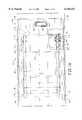
- FIG. 1Ais a plan view of a dispensing table-cushioning conversion machine combination according to the present invention, the combination including a dispensing table and a cushioning conversion machine guided therebeneath for movement between the illustrated operating position of the machine and a side withdrawn or pulled-out position.
- FIG. 1Bis a front elevational view of the table-machine combination shown in FIG. 1A.
- FIG. 2Ais a fragmentary plan view of the table-machine combination of FIG. 1A, showing the machine withdrawn from one side of the table.
- FIG. 2Bis a fragmentary front elevational view of the table-machine combination in its position shown in FIG. 2A.
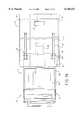
- FIG. 3Ais a top view of an alternative configuration of the table-machine combination according to the present invention, the machine being guided for transverse movement between the illustrated operating position and a front withdrawn position.
- FIG. 3Bis an end elevational view of the table-machine combination shown in FIG. 3A.
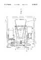
- FIG. 4Ais a fragmentary plan view of the table/machine combination shown in FIG. 3A illustrating the machine pulled out to the front of the table in solid and the machine pulled out (alternatively) to the back of the table in phantom.
- FIG. 4Bis a side elevational view of the table-machine combination shown in FIG. 4A.
- FIG. 5Ais an enlarged plan view of an exemplary guide assembly.
- FIG. 5Bis a side view of the guide assembly shown in FIG. 5A.
- FIG. 6is an enlarged fragmentary elevational view illustrating an exemplary leg of the table and exemplary leg support of the machine.
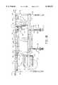
- FIG. 7is a plan view showing internal components of an exemplary cushioning conversion machine useful in practicing the present invention.
- FIGS. 1 and 2show one configuration 8' of the table-machine combination for side withdrawal of the machine from beneath the table, and FIGS. 3 and 4 show another configuration 8' for front (or rear) withdrawal of the machine.
- the cushioning conversion machine 12has an upper housing 16 which houses various conversion assemblies (as discussed below in connection with FIG. 7) that convert stock material, such as multiply kraft paper, into a dunnage product.
- the housing 16is supported on a cart 18 including a plurality of vertical support members or legs 20.
- the support members 20each include a caster 22 at its lower end to permit the machine 12 to move with relative ease only in a direction perpendicular to the rotation axis of the caster wheel.
- the casters 22(or more particularly the wheels thereof) can be oriented, as in the manner hereinafter described, to permit the machine 12 to move in a direction parallel to a longitudinal axis of the table 10 (FIGS. 1 and 2) or to permit the machine 12 to move in a direction perpendicular to the longitudinal axis (FIGS. 3 and 4).
- the guide system 14 illustrated in FIGS. 1-4can also be disposed in alternative configurations to permit movement of the machine parallel to or perpendicular to the longitudinal axis of the table.
- the guide system 14includes guide tracks 30 and followers 32.
- the guide tracks 30can be arranged parallel to the longitudinal axis of the table 10 (FIGS. 1 and 2) allowing movement of the machine out the side of the table. Alternatively, the tracks 30 can be rotated 90 degrees to provide for movement of the machine out the front (or rear) of the table (FIGS. 3 and 4).
- the support members 20form four vertical legs of the cart 18.
- the support members 20are constructed from square, tubular steel, and include a fixed upper portion 42 and a telescoping lower portion 44 which moves in and out of the interior of the fixed portion 42.
- Each upper portion 42includes a vertical slot 46 which is designed to receive a removable lock or latch device 48, such as one or more bolts.
- Each lower portion 44includes a plurality of holes 50 for selective receipt of the bolt or bolts 48 to fix the lower portion 44 in relation to the upper portion 42 at a selected extension length, whereby the vertical height of the housing 16 may be adjusted.
- the holes 50 in the lower portionprovide for rough incremental adjustment of the length of the legs 20 while the vertical slots 46 in the upper portions of the legs provide infinite fine adjustment of the length of the legs over a limited range. This is advantageous for proper leveling of the machine even when the underlying floor is not level.
- the lower portion 44 of each leg 20preferably has a close sliding fit in the upper portion 42 to provide a stable support for the conversion assemblies housed in or mounted to the housing 16. Also, the square cross-sections of the upper and lower portions cooperate to prevent relative rotation therebetween when telescoped together. Being square, the lower portion can be inserted into the upper portion at 90 rotated positions for allowing selection of the position of the casters between one with the wheel axis oriented perpendicular to the longitudinal axis of the table (FIGS.
- the dispensing table 10comprises a horizontal work platform or table top 60 supported on a rectangular frame 62.
- the work platform 60may be approximately 83 wide and 42 inches deep, for example.
- the work platformhas an opening 66 through which (when the machine 12 is slid to the operating position and is operating) cushioning products, or pads, are discharged for easy access by a packaging person who may grab the dispensed pad (or other dunnage product and) place the pad in a shipping box supported on the work platform to fill any voids and/or to cushion an item in the box.
- the table frame 62includes four vertical legs 64 which are telescopically adjustable to position the work platform 60 at a convenient height for a worker performing packaging duties.
- the tablewill have a maximum height of approximately 3 feet, with each leg having a range of adjustment of approximately 7 inches.
- the height of the table top 10may range from approximately 29 inches to approximately 36 inches.
- the vertical support members or legs 64are preferably located at each corner of the work platform 60.
- the longitudinal spacing between the legs at the front and rear of the tableis preferably greater than the length of the entire cushioning conversion machine, including a stock roll S supported on a stock roll holder 67 mounted to the housing 16 of the machine 12. This spacing of the legs will permit the machine to be removed from underneath the table out either the front or back of the table.
- the spacing between the front and rear legs at each side of the tableis greater than the overall width of the machine, as best illustrated in FIG. 3B. This spacing permits the machine to be moved from underneath the table out either side of the table.
- the table frame 62further includes horizontal frame members or braces 68 and 69 extending between relatively adjacent legs.
- the braces 68 extending between the legs 64 at the front and rear of the tableare longer than the braces extending between the legs at the sides of the table.
- the respective long and short bracesare identical and interchangeable with one another, i.e., front-to-back or side-to-side.
- the bracesare removably attached by suitable fastening means such as fasteners, latching devices, hooks, etc.
- suitable fastening meanssuch as fasteners, latching devices, hooks, etc.
- one of the illustrated braceswill be removed to permit withdrawal of the machine at the corresponding end of the table, be it the front, rear or a side of the table.
- a single long and single short braceshould be sufficient for most applications.
- the dispensing table 10has guide system 14 assembled with respect thereto.
- the guide tracksare secured to the table and the followers to the machine.
- the followersare arranged one for each tract and are secured to the machine at its trailing end taken in relation to the direction that the machine is withdrawn from the table. In the illustrated embodiment, two followers are provided at respective corners of the machine.
- front and rear guide tracts 30each including a guide rail 72 and a guide rail extension 72.
- the main guide rail 70 and guide rail extension 72are channel members which are attached at the base of the channel to the bottom surface of the work platform 60 by suitable fastening means such as screws, bolts, clips, adhesives, etc.
- the railsare removably secured to the table for easy reconfiguring of the table-machine for a different use as may be desired.
- the railsmay be more permanently fixed in place for a given application.
- the pair of guide tracksare parallel to one another and run lengthwise on the table 10 in FIGS. 1 and 2. This orientation of the guide tracks permits the machine 12 to be pulled out the side of the table 10. (See FIGS. 2A and 2B.)
- the guide rails 70are shorter than the width of table 10, such that in the alternative configuration of the table-machine combination shown in FIGS. 3 and 4, the guide rails 70 can be rotated 90 degrees and still fit within the width of the work platform 60 without projecting forwardly or rearwardly therefrom.
- Stops 80 and 82are provided at opposite ends of the guide tracks 30. Stops 80 are located to limit the extent of side withdrawal of the machine 12 and to prevent the follower 32 from running off the guide track. Stops 82 are located to provide a positive stop for aligning an exit opening 84 of a post-cutting constraining assembly 86 of the machine 12 with the opening 66 in the work platform 60. In the illustrated embodiment, the stops are engaged by the followers 32, but they could be positioned to interfere with any portion of the machine. As a further modification, the stops (or stop), or other obstruction may be positioned elsewhere on the table to interfere and limit movement of the machine in one or both directions.
- the overall configuration of the guide tracks 30, followers 32 and casters 22 illustrated in FIGS. 1A and 1Bpermits the machine 12 to move parallel to the longitudinal axis of the table and thus out a side of table 10 as illustrated in FIGS. 2A and 2B.
- the machine 12In this withdrawn position, the machine 12 can be easily loaded with stock material as the stock roll holder is then easily accessible for loading a stock roll thereon.
- an access door 85 in the top of the machine housingmay be accessed and opened for feeding the end of a new roll of stock material through the machine. Furthermore, maintenance on internal components of the conversion assemblies can be easily performed.
- FIGS. 3 and 4illustrate an alternative configuration of the table 10 and machine 12 which will permit the machine to move perpendicular to the longitudinal axis of the table.
- the guide rail extensions 72are not used and the guide rails 70 are secured to the underside of the table top 60 parallel to the transverse axis of the table (as discussed previously, the length of guide rails 70 is less than the depth of the table 10).
- the lower portions 44 of the legs 20are rotated 90 degrees, such that the casters 22 are oriented to permit movement of the machine perpendicular to the longitudinal axis of the table.
- the followers 32engage the guide rails 70 to guide the machine 12 out the front (or back) of the table 10, as illustrated in FIGS. 4A and 4B.
- the machinewas guided out the side of the table 10, it can now be loaded with stock material and/or have maintenance performed thereon with relative ease.
- the followers 32preferably are identical and interchangeable, each including a mounting bracket 90 and rollers 92.
- the mounting bracket 90is generally L-shape with the rollers 92 mounted to one leg 94 and the other leg 96 being adapted for attachment to the machine housing 16, as by any suitable fastening means.
- the followeris removably secured to the machine housing for easy adaptability to different configurations, such as that shown in FIGS. 1 and 2 on the one hand and FIGS. 3 and 4 on the other hand.
- the rollers 92are rotatably mounted to leg member 94 and arranged so to engage the sides of the respective guide rail 70.
- the rollers 92are symmetrically arranged to create a pair of intersecting paths for receiving the guide rail, one path being used when the guide rail extends parallel to the longitudinal axis of the table and the other being used when the guide rail extends perpendicular to the longitudinal axis.
- the rollers 92are disposed at the four corners of an imaginary square such that the axes of the two paths 93 and 95 are perpendicular to one another for the above indicated usage.
- the stop 82is positioned on the guide rail and projects therebeneath to engage the end of the leg 94 of the bracket 90.
- FIG. 6further illustrates the legs 64 of the table 10 and legs 20 of the machine 12.
- the legs 20 of the machine 12are vertically adjustable and provide for rotation of the casters between two orientations.
- the legs 20 of the preferred embodimenthave a pair of hex-bolts which pass through the slot 46 and holes 50. The hex-bolts cooperate with nuts (not shown) located on the opposite side of the support member for tightening into engagement with the upper leg portion, thereby fixing the height of the machine 12.
- the legs 64 of the table 10are also vertically adjustable.
- the legs 64each have a fixed upper portion 91 and a telescoping lower portion 97.
- the lower portion 97does not have a plurality of holes, but rather has a vertically extending slot 99 which receives a lock bolt 101.
- the lock boltcooperates with a nut to secure the position of the lower portion relative to the upper portion of the leg.
- the cushioning conversion machine 12is shown loaded with a roll S of sheet-like stock material 98.
- the stock materialmay consist of three superimposed webs of biodegradable, recyclable and reusable paper rolled onto a hollow cylindrical tube.
- the machine 12converts the stock material into a continuous unconnected strip having lateral pillow-like portions separated by a thin central band. This strip is coined along its central band to form a coined strip which is cut into sections, or pads, of a desired length.
- the housing 16 of the cushioning conversion machine 10includes a frame 40 having a base plate 100, a pair of lateral side plates 102, an upstream end plate 104, a downstream end plate 106, a top plate 108, and back door 110. Because the machine 12 is positioned in a substantially horizontal manner, the imaginary longitudinal axis of the machine from its upstream end to its downstream end is substantially horizontal.
- the base plate 100 and the side plates 102are essentially solid rectangular sheets.
- the end plates 104 and 106are also rectangular, however they are not solid. Instead, the upstream end plate 104 includes a large inlet opening which essentially results in the plate 104 resembling a border, rather than a plate.
- the downstream end plate 106includes a relatively small outlet opening.
- the top plate 108has the access door or top cover 85 attached thereto by a hinge 112 for opening and closing an access opening in the top plate.
- the hinged top cover 85allows access to the internal conversion assemblies for necessary maintenance and feeding of paper during loading.
- the hinge 112may be disposed along any one of the four edges of the top cover 108 depending upon the direction of withdrawal movement of the machine relative to the table 12. For example, if the machine 12 and table 10 were configured such that the machine 12 moved parallel to the longitudinal axis of the table and out the side of table, the hinge 112 would be disposed along the edge of the top cover 85 closest the downstream end plate 106, or possibly the upstream end plate 104. Alternatively, if the machine were configured as shown in FIGS.
- the hinge 112would be disposed along the edge of the top cover 85 which is closest either of the lateral side plates 102, depending upon which direction (backwards or forwards) the machine 12 was to be moved.
- the hinge 112is disposed along the edge of the top cover 85 which exits the table last, e.g., if the machine moves in an upstream direction (i.e., to the position in FIG. 2A), the hinge is located on the edge of the top cover closest the downstream end plate.
- stock materialis fed through the machine and converted into a cushioning product.
- the cushioning productis then cut into sections or pads and these cut sections then travel through the post-cutting constraining assembly 86.
- the post-cutting constraining assembly 86extends outwardly from the back plate 110 and its overall geometry approximates a generally 90 degree curved arc.
- the exit opening 84 of the post-cutting constraining assembly 86is the final outlet of the machine 12 as the cushioning product emerges through this outlet during operation of the machine.
- the machine 12When the machine 12 is positioned in the operating position, its final outlet 84 is aligned with the table's opening 66 whereby the pads will be deposited on the work platform 60.
- the above described table-machine combinationis beneficial even if only used in connection with the operating position thereof because it allows for easy alignment of the machine's final outlet 84 and the table's opening 66.
- the table 10may be modified to include multiple dispensing openings and the table-machine combination would allow a packaging person to select a desired dispensing opening.
- FIG. 7generally illustrates the internal conversion assembles of a preferred cushioning conversion machine such as that shown in U.S. Pat. No 5,123,889 to which reference may be had for further details.
- the machine 12includes a separating assembly 119 (FIG. 1B), a forming assembly 120, a feed gear assembly 122, a cutting assembly 124, and the post-cutting constraining assembly 86.
- the general operation of these assembliesis described in detail in U.S. Pat. No. 5,123,889.
- the table/machine combination of the present inventionallows for convenient loading of stock material, easy threading of stock material, and/or handy maintenance of certain components of the machine. Furthermore, one skilled in the art will appreciate that the table/machine combination of the present invention will reduce the need for custom engineering to meet individual needs through the use of a guide system which can be oriented to permit removal of the machine out the front, back or side of the table.
Landscapes
- Engineering & Computer Science (AREA)
- Mechanical Engineering (AREA)
- Life Sciences & Earth Sciences (AREA)
- Forests & Forestry (AREA)
- Buffer Packaging (AREA)
Abstract
Description
Claims (4)
Priority Applications (1)
| Application Number | Priority Date | Filing Date | Title |
|---|---|---|---|
| US08/892,858US6146321A (en) | 1993-05-21 | 1997-07-15 | Dispensing table and guide system for a cushioning conversion machine |
Applications Claiming Priority (4)
| Application Number | Priority Date | Filing Date | Title |
|---|---|---|---|
| US6633793A | 1993-05-21 | 1993-05-21 | |
| US08/155,931US5487717A (en) | 1993-05-21 | 1993-11-23 | Dispensing table for a cushioning conversion machine |
| US08/438,238US5681255A (en) | 1993-05-21 | 1995-05-09 | Dispensing table and guide system for a cushioning conversion machine |
| US08/892,858US6146321A (en) | 1993-05-21 | 1997-07-15 | Dispensing table and guide system for a cushioning conversion machine |
Related Parent Applications (1)
| Application Number | Title | Priority Date | Filing Date |
|---|---|---|---|
| US08/438,238ContinuationUS5681255A (en) | 1993-05-21 | 1995-05-09 | Dispensing table and guide system for a cushioning conversion machine |
Publications (1)
| Publication Number | Publication Date |
|---|---|
| US6146321Atrue US6146321A (en) | 2000-11-14 |
Family
ID=23739824
Family Applications (2)
| Application Number | Title | Priority Date | Filing Date |
|---|---|---|---|
| US08/438,238Expired - LifetimeUS5681255A (en) | 1993-05-21 | 1995-05-09 | Dispensing table and guide system for a cushioning conversion machine |
| US08/892,858Expired - LifetimeUS6146321A (en) | 1993-05-21 | 1997-07-15 | Dispensing table and guide system for a cushioning conversion machine |
Family Applications Before (1)
| Application Number | Title | Priority Date | Filing Date |
|---|---|---|---|
| US08/438,238Expired - LifetimeUS5681255A (en) | 1993-05-21 | 1995-05-09 | Dispensing table and guide system for a cushioning conversion machine |
Country Status (2)
| Country | Link |
|---|---|
| US (2) | US5681255A (en) |
| WO (1) | WO1996035576A1 (en) |
Cited By (9)
| Publication number | Priority date | Publication date | Assignee | Title |
|---|---|---|---|---|
| US6503182B2 (en)* | 2001-03-29 | 2003-01-07 | Zsolt Design Engineering, Inc. | Compact apparatus and system for creating and dispensing cushioning dunnage |
| US20030087741A1 (en)* | 2001-03-29 | 2003-05-08 | Zsolt Toth | Method, apparatus and system for making cushioning product, and roll tensioner therefor |
| US6673001B2 (en) | 2001-03-29 | 2004-01-06 | Zsolt Toth | Compact apparatus and system for creating and dispensing cushioning dunnage |
| US20040266598A1 (en)* | 2001-03-29 | 2004-12-30 | Zsolt Toth | Cushioning conversion system and method |
| US20060196043A1 (en)* | 2005-03-07 | 2006-09-07 | Scott Holloway | Boiler wall tube welding tool |
| US20060253635A1 (en)* | 2001-10-12 | 2006-11-09 | Mips Technologies, Inc. | Method and apparatus for binding shadow registers to vectored interrupts |
| US20080014072A1 (en)* | 2006-07-13 | 2008-01-17 | Jorg Von Seggern Maschinenbau Gmbh | Configuration for accommodating, transferring and/or transporting at least one functional part of a technical device |
| US20140106954A1 (en)* | 2012-10-12 | 2014-04-17 | Storopack Hans Reichenecker Gmbh | Device for making a paper pad product |
| CN107344428A (en)* | 2017-07-14 | 2017-11-14 | 芜湖德丰汽车零部件有限公司 | One kind cutting bonding all-in-one |
Families Citing this family (16)
| Publication number | Priority date | Publication date | Assignee | Title |
|---|---|---|---|---|
| US5681255A (en)* | 1993-05-21 | 1997-10-28 | Ranpak Corp. | Dispensing table and guide system for a cushioning conversion machine |
| US5902223A (en)* | 1995-10-06 | 1999-05-11 | Ranpak Corp. | Cushoning conversion machine |
| AU3590297A (en) | 1996-06-28 | 1998-01-21 | Ranpak Corp. | Cushioning conversion machine |
| US6090033A (en)* | 1997-09-02 | 2000-07-18 | Ranpak Corp. | Cushioning conversion machine for producing U-shape pads |
| EP1310355B1 (en)* | 1998-01-12 | 2009-04-22 | Ranpak Corp. | Cushioning Conversion Device |
| DE19830650C1 (en)* | 1998-07-09 | 1999-08-12 | Lohmann Therapie Syst Lts | Dry copying to give bonded active ingredients at a substrate surface for transdermal therapy |
| US6179765B1 (en) | 1998-10-30 | 2001-01-30 | Ft Acquisition, L.P. | Paper dispensing system and method |
| US6076764A (en)* | 1998-10-30 | 2000-06-20 | F.T. Acquisitions, L.P. | Combination paper roll core and paper tube plug |
| US6632165B1 (en) | 2000-11-01 | 2003-10-14 | Guy Letourneau | Paper conversion dispenser machine |
| EP2799223A3 (en) | 2003-07-07 | 2014-12-31 | Ranpak Corp. | Cutterless dunnage converter and method |
| US6910997B1 (en)* | 2004-03-26 | 2005-06-28 | Free-Flow Packaging International, Inc. | Machine and method for making paper dunnage |
| US8167783B2 (en) | 2006-04-11 | 2012-05-01 | Pack-Tiger Gmbh | Machine for the manufacture of paper padding |
| DE102012216020B4 (en)* | 2012-09-10 | 2023-07-13 | Demmeler Automatisierung Und Roboter Gmbh | Sliding system for an assembly or welding table |
| DE102012218680A1 (en)* | 2012-10-12 | 2014-04-17 | Storopack Hans Reichenecker Gmbh | Apparatus for producing a padding product from paper |
| US20150352802A1 (en)* | 2014-06-09 | 2015-12-10 | Storopack, Inc. | Protective packaging work station |
| US9358679B2 (en)* | 2014-08-07 | 2016-06-07 | Amaesing Tool Manufacturing Inc. | Mobile work station |
Citations (12)
| Publication number | Priority date | Publication date | Assignee | Title |
|---|---|---|---|---|
| US2599096A (en)* | 1950-07-07 | 1952-06-03 | Fred L Spicknall | Portable workbench for powerdriven hand and table tools |
| FR2326271A1 (en)* | 1975-10-03 | 1977-04-29 | Garnier Louis | Single station prodn. line feeding products in turn - has parts to hand in movable cases and has carriage chain on spiral ramps in table |
| US4076230A (en)* | 1975-06-12 | 1978-02-28 | Jerome S. Marger | Portable, readily storable patient treatment table |
| US4237776A (en)* | 1978-06-02 | 1980-12-09 | Ranpak Corporation | Cushioning dunnage mechanism |
| DE9005310U1 (en)* | 1990-05-10 | 1990-08-16 | Hubeny, Peter, 6908 Wiesloch | Workbench element with a movable support for a work tool |
| WO1992005948A1 (en)* | 1990-10-05 | 1992-04-16 | Ranpak Corporation | Downsized cushioning dunnage conversion machine and packaging systems employing the same |
| US5116249A (en)* | 1989-08-11 | 1992-05-26 | Ryobi Limited | Table saw |
| US5173987A (en)* | 1991-04-12 | 1992-12-29 | Abington, Inc. | Rotary air jet screen cleaning device |
| US5201863A (en)* | 1992-03-02 | 1993-04-13 | Ryobi Motor Products Corporation | Miter table assembly for a table saw |
| WO1995014569A1 (en)* | 1993-11-23 | 1995-06-01 | Ranpak Corp. | Dispensing table for a cushioning conversion machine |
| US5542232A (en)* | 1993-11-19 | 1996-08-06 | Ranpak Corp. | Transitional slide for use with a cushion-creating machine |
| US5681255A (en)* | 1993-05-21 | 1997-10-28 | Ranpak Corp. | Dispensing table and guide system for a cushioning conversion machine |
Family Cites Families (1)
| Publication number | Priority date | Publication date | Assignee | Title |
|---|---|---|---|---|
| US5173978A (en)* | 1990-11-20 | 1992-12-29 | Aprica Kassai Kabushikikaisha | Bed apparatus provided with bathtub |
- 1995
- 1995-05-09USUS08/438,238patent/US5681255A/ennot_activeExpired - Lifetime
- 1996
- 1996-05-08WOPCT/US1996/006497patent/WO1996035576A1/enactiveApplication Filing
- 1997
- 1997-07-15USUS08/892,858patent/US6146321A/ennot_activeExpired - Lifetime
Patent Citations (14)
| Publication number | Priority date | Publication date | Assignee | Title |
|---|---|---|---|---|
| US2599096A (en)* | 1950-07-07 | 1952-06-03 | Fred L Spicknall | Portable workbench for powerdriven hand and table tools |
| US4076230A (en)* | 1975-06-12 | 1978-02-28 | Jerome S. Marger | Portable, readily storable patient treatment table |
| FR2326271A1 (en)* | 1975-10-03 | 1977-04-29 | Garnier Louis | Single station prodn. line feeding products in turn - has parts to hand in movable cases and has carriage chain on spiral ramps in table |
| US4237776A (en)* | 1978-06-02 | 1980-12-09 | Ranpak Corporation | Cushioning dunnage mechanism |
| US5116249A (en)* | 1989-08-11 | 1992-05-26 | Ryobi Limited | Table saw |
| DE9005310U1 (en)* | 1990-05-10 | 1990-08-16 | Hubeny, Peter, 6908 Wiesloch | Workbench element with a movable support for a work tool |
| WO1992005948A1 (en)* | 1990-10-05 | 1992-04-16 | Ranpak Corporation | Downsized cushioning dunnage conversion machine and packaging systems employing the same |
| US5123889A (en)* | 1990-10-05 | 1992-06-23 | Ranpak Corporation | Downsized cushioning dunnage conversion machine and cutting assemblies for use on such a machine |
| US5173987A (en)* | 1991-04-12 | 1992-12-29 | Abington, Inc. | Rotary air jet screen cleaning device |
| US5201863A (en)* | 1992-03-02 | 1993-04-13 | Ryobi Motor Products Corporation | Miter table assembly for a table saw |
| US5487717A (en)* | 1993-05-21 | 1996-01-30 | Ranpak Corp. | Dispensing table for a cushioning conversion machine |
| US5681255A (en)* | 1993-05-21 | 1997-10-28 | Ranpak Corp. | Dispensing table and guide system for a cushioning conversion machine |
| US5542232A (en)* | 1993-11-19 | 1996-08-06 | Ranpak Corp. | Transitional slide for use with a cushion-creating machine |
| WO1995014569A1 (en)* | 1993-11-23 | 1995-06-01 | Ranpak Corp. | Dispensing table for a cushioning conversion machine |
Cited By (19)
| Publication number | Priority date | Publication date | Assignee | Title |
|---|---|---|---|---|
| US20070117704A1 (en)* | 2001-03-29 | 2007-05-24 | Zsolt Toth | Compact apparatus and system for creating and dispensing cushioning dunnage |
| US7172548B2 (en) | 2001-03-29 | 2007-02-06 | Zsolt Design Engineering, Inc. | Cushioning conversion system and method |
| US6673001B2 (en) | 2001-03-29 | 2004-01-06 | Zsolt Toth | Compact apparatus and system for creating and dispensing cushioning dunnage |
| US7163503B2 (en) | 2001-03-29 | 2007-01-16 | Zsolt Design Engineering, Inc. | Compact apparatus and system for creating and dispensing cushioning dunnage |
| US20040266598A1 (en)* | 2001-03-29 | 2004-12-30 | Zsolt Toth | Cushioning conversion system and method |
| US7022060B2 (en) | 2001-03-29 | 2006-04-04 | Zsolt Design Engineering, Inc. | Method, apparatus and system for making cushioning product, and roll tensioner therefor |
| US20060135336A1 (en)* | 2001-03-29 | 2006-06-22 | Zsolt Toth | Method, apparatus and system for making cushioning product, and roll tensioner therefor |
| US7479100B2 (en) | 2001-03-29 | 2009-01-20 | Zsolt Design Engineering, Inc. | Cushioning conversion system and method |
| US20030087741A1 (en)* | 2001-03-29 | 2003-05-08 | Zsolt Toth | Method, apparatus and system for making cushioning product, and roll tensioner therefor |
| US7347809B2 (en) | 2001-03-29 | 2008-03-25 | Zsolt Design Engineering, Inc. | Compact apparatus and system for creating and dispensing cushioning dunnage |
| US20040043883A1 (en)* | 2001-03-29 | 2004-03-04 | Zsolt Toth | Compact apparatus and system for creating and dispensing cushioning dunnage |
| US20070117705A1 (en)* | 2001-03-29 | 2007-05-24 | Zsolt Toth | Cushioning conversion system and method |
| US6503182B2 (en)* | 2001-03-29 | 2003-01-07 | Zsolt Design Engineering, Inc. | Compact apparatus and system for creating and dispensing cushioning dunnage |
| US7335151B2 (en) | 2001-03-29 | 2008-02-26 | Zsolt Design Engineering, Inc. | Method, apparatus and system for making cushioning product, and roll tensioner therefor |
| US20060253635A1 (en)* | 2001-10-12 | 2006-11-09 | Mips Technologies, Inc. | Method and apparatus for binding shadow registers to vectored interrupts |
| US20060196043A1 (en)* | 2005-03-07 | 2006-09-07 | Scott Holloway | Boiler wall tube welding tool |
| US20080014072A1 (en)* | 2006-07-13 | 2008-01-17 | Jorg Von Seggern Maschinenbau Gmbh | Configuration for accommodating, transferring and/or transporting at least one functional part of a technical device |
| US20140106954A1 (en)* | 2012-10-12 | 2014-04-17 | Storopack Hans Reichenecker Gmbh | Device for making a paper pad product |
| CN107344428A (en)* | 2017-07-14 | 2017-11-14 | 芜湖德丰汽车零部件有限公司 | One kind cutting bonding all-in-one |
Also Published As
| Publication number | Publication date |
|---|---|
| US5681255A (en) | 1997-10-28 |
| WO1996035576A1 (en) | 1996-11-14 |
Similar Documents
| Publication | Publication Date | Title |
|---|---|---|
| US6146321A (en) | Dispensing table and guide system for a cushioning conversion machine | |
| US5816995A (en) | Dispensing table for cushioning conversion machine | |
| US6077209A (en) | Downsized cushioning dunnage conversion machine and cutting assemblies for use on such a machine | |
| US5468208A (en) | Downsized cushioning dunnage conversion machine and packaging systems employing the same | |
| US5674172A (en) | Cushioning conversion machine having a single feed/cut handle | |
| EP0873857B1 (en) | Cushioning conversion machine and method | |
| US5637071A (en) | Dispensing table for a cushioning conversion machine | |
| US5902223A (en) | Cushoning conversion machine | |
| HK1007988B (en) | Cushioning dunnage conversion machine and method of producing cut sections of cushioning dunnage product | |
| US20030092552A1 (en) | Cushioning conversion machine and method | |
| US5803893A (en) | Cushioning conversion machine and method | |
| US5542232A (en) | Transitional slide for use with a cushion-creating machine | |
| US5658229A (en) | Downsized cushioning dumnage conversion machine and cutting assemblies for use on such a machine | |
| US5709642A (en) | Cushioning conversion machine and method | |
| US5997461A (en) | Cushioning conversion machine and method | |
| WO1996040494A1 (en) | Cushioning conversion system having horizontally pivotable mounting relative to a stand | |
| US5908375A (en) | Manual feed cushioning machine and method | |
| US6135939A (en) | Cushioning conversion machine and method | |
| AU702211B2 (en) | Downsized cushioning dunnage conversion machine and packaging systems employing the same | |
| WO1996037361A1 (en) | A combined packing table and cushioning conversion machine; and a related method of producing filled packages |
Legal Events
| Date | Code | Title | Description |
|---|---|---|---|
| STCF | Information on status: patent grant | Free format text:PATENTED CASE | |
| AS | Assignment | Owner name:GENERAL ELECTRIC CAPITAL CORPORATION, AS AGENT, CO Free format text:SECURITY AGREEMENT;ASSIGNOR:RANPAK CORP.;REEL/FRAME:012418/0493 Effective date:20011228 | |
| FPAY | Fee payment | Year of fee payment:4 | |
| AS | Assignment | Owner name:GENERAL ELECTRIC CAPITAL CORPORATION, CONNECTICUT Free format text:SECURITY AGREEMENT;ASSIGNOR:RANPAK CORP.;REEL/FRAME:014709/0832 Effective date:20040526 | |
| AS | Assignment | Owner name:SPECIAL SITUATIONS INVESTING GROUP, INC., NEW YORK Free format text:SECURITY AGREEMENT;ASSIGNOR:RANPAK CORP.;REEL/FRAME:015676/0883 Effective date:20040727 | |
| FEPP | Fee payment procedure | Free format text:PAT HOLDER NO LONGER CLAIMS SMALL ENTITY STATUS, ENTITY STATUS SET TO UNDISCOUNTED (ORIGINAL EVENT CODE: STOL); ENTITY STATUS OF PATENT OWNER: LARGE ENTITY | |
| AS | Assignment | Owner name:GENERAL ELECTRIC CAPITAL CORPORATION, AS AGENT, CO Free format text:SECURITY INTEREST;ASSIGNOR:RANPAK CORP;REEL/FRAME:015861/0341 Effective date:20050317 | |
| AS | Assignment | Owner name:RANPAK CORP, OHIO Free format text:RELEASE OF SECURITY INTEREST;ASSIGNOR:SPECIAL SITUATIONS INVESTING GROUP, INC.;REEL/FRAME:016784/0231 Effective date:20041104 | |
| AS | Assignment | Owner name:GENERAL ELECTRIC CAPITAL CORPROATION, CONNECTICUT Free format text:SECURITY AGREEMENT;ASSIGNOR:RANPAK CORP.;REEL/FRAME:016945/0612 Effective date:20051214 | |
| AS | Assignment | Owner name:RANPAK CORP., OHIO Free format text:RELEASE OF SECURITY INTEREST;ASSIGNOR:GENERAL ELECTRIC CAPITAL CORPORATION;REEL/FRAME:016967/0696 Effective date:20051214 Owner name:RANPAK CORP., OHIO Free format text:RELEASE OF SECURITY INTEREST;ASSIGNOR:GENERAL ELECTRIC CAPITAL CORPORATION;REEL/FRAME:016976/0302 Effective date:20051214 Owner name:RANPAK CORP., OHIO Free format text:RELEASE OF SECURITY INTEREST;ASSIGNOR:GENERAL ELECTRIC CAPITAL CORPORATION;REEL/FRAME:016976/0285 Effective date:20051214 | |
| AS | Assignment | Owner name:RANPAK CORP., OHIO Free format text:RELEASE OF SECURITY INTEREST INTELLECTUAL PROPERTY COLLATERAL;ASSIGNOR:GENERAL ELECTRIC CAPITAL CORPORATION, AS AGENT;REEL/FRAME:020362/0864 Effective date:20071227 Owner name:RANPAK CORP.,OHIO Free format text:RELEASE OF SECURITY INTEREST INTELLECTUAL PROPERTY COLLATERAL;ASSIGNOR:GENERAL ELECTRIC CAPITAL CORPORATION, AS AGENT;REEL/FRAME:020362/0864 Effective date:20071227 | |
| AS | Assignment | Owner name:AMERICAN CAPITAL FINANCIAL SERVICES, INC., AS AGEN Free format text:FIRST LIEN PATENT SECURITY AGREEMENT;ASSIGNOR:RANPAK CORP.;REEL/FRAME:020690/0276 Effective date:20071227 | |
| AS | Assignment | Owner name:AMERICAN CAPITAL FINANCIAL SERVICES, INC., AS AGEN Free format text:SECOND LIEN PATENT SECURITY AGREEMENT;ASSIGNOR:RANPAK CORP.;REEL/FRAME:020497/0927 Effective date:20071227 | |
| FPAY | Fee payment | Year of fee payment:8 | |
| AS | Assignment | Owner name:RANPAK CORP., OHIO Free format text:RELEASE BY SECURED PARTY;ASSIGNOR:AMERICAN CAPITAL, LTD. (SUCCESSOR TO AMERICAN CAPITAL FINANCIAL SERVICES, INC.);REEL/FRAME:026159/0237 Effective date:20110420 Owner name:RANPAK CORP., OHIO Free format text:RELEASE BY SECURED PARTY;ASSIGNOR:AMERICAN CAPITAL, LTD. (SUCCESSOR TO AMERICAN CAPITAL FINANCIAL SERVICES, INC.);REEL/FRAME:026159/0279 Effective date:20110420 | |
| AS | Assignment | Owner name:GOLDMAN SACHS LENDING PARTNERS LLC, NEW YORK Free format text:SECURITY AGREEMENT;ASSIGNOR:RANPAK CORP.;REEL/FRAME:026161/0305 Effective date:20110420 | |
| AS | Assignment | Owner name:BANK OF AMERICA, N.A., AS COLLATERAL AGENT, CALIFO Free format text:PATENT SECURITY AGREEMENT;ASSIGNOR:RANPAK CORP.;REEL/FRAME:026276/0638 Effective date:20110420 | |
| FPAY | Fee payment | Year of fee payment:12 | |
| AS | Assignment | Owner name:GOLDMAN SACHS BANK USA, NEW JERSEY Free format text:SECURITY AGREEMENT;ASSIGNOR:RANPAK CORP.;REEL/FRAME:030271/0112 Effective date:20130423 Owner name:RANPAK CORP., OHIO Free format text:RELEASE BY SECURED PARTY;ASSIGNOR:BANK OF AMERICA, N.A., AS COLLATERAL AGENT;REEL/FRAME:030271/0097 Effective date:20130423 Owner name:RANPAK CORP., OHIO Free format text:RELEASE BY SECURED PARTY;ASSIGNOR:GOLDMAN SACHS LENDING PARTNERS LLC;REEL/FRAME:030271/0031 Effective date:20130423 | |
| AS | Assignment | Owner name:GOLDMAN SACHS BANK USA, AS COLLATERAL AGENT, NEW J Free format text:SECURITY AGREEMENT;ASSIGNOR:RANPAK CORP.;REEL/FRAME:030276/0413 Effective date:20130423 | |
| AS | Assignment | Owner name:RANPAK CORP., OHIO Free format text:TERMINATION OF SECURITY INTEREST IN PATENTS (FIRST LIEN);ASSIGNOR:GOLDMAN SACHS BANK USA;REEL/FRAME:049218/0049 Effective date:20141001 Owner name:RANPAK CORP., OHIO Free format text:TERMINATION OF SECURITY INTEREST IN PATENTS (SECOND LIEN);ASSIGNOR:GOLDMAN SACHS BANK USA;REEL/FRAME:049217/0429 Effective date:20141001 |