US6145671A - Integrated display system for death care merchandise - Google Patents
Integrated display system for death care merchandiseDownload PDFInfo
- Publication number
- US6145671A US6145671AUS09/115,159US11515998AUS6145671AUS 6145671 AUS6145671 AUS 6145671AUS 11515998 AUS11515998 AUS 11515998AUS 6145671 AUS6145671 AUS 6145671A
- Authority
- US
- United States
- Prior art keywords
- display unit
- back wall
- display
- unit
- horizontal
- Prior art date
- Legal status (The legal status is an assumption and is not a legal conclusion. Google has not performed a legal analysis and makes no representation as to the accuracy of the status listed.)
- Expired - Lifetime
Links
Images


Classifications
- A—HUMAN NECESSITIES
- A47—FURNITURE; DOMESTIC ARTICLES OR APPLIANCES; COFFEE MILLS; SPICE MILLS; SUCTION CLEANERS IN GENERAL
- A47F—SPECIAL FURNITURE, FITTINGS, OR ACCESSORIES FOR SHOPS, STOREHOUSES, BARS, RESTAURANTS OR THE LIKE; PAYING COUNTERS
- A47F7/00—Show stands, hangers, or shelves, adapted for particular articles or materials
- A47F7/30—Show stands, hangers, or shelves, adapted for particular articles or materials for furniture, e.g. beds, mattresses
Definitions
- the present inventionrelates to an integrated display system for death care merchandise such as caskets, coffins, urns, burial vaults and materials for decorating or adorning or promoting or advising the same.
- the display system of the inventionis particularly designed for use by prospective purchasers in a preview room.
- the display systemincludes an apparatus by which miniaturized death care merchandise is displayed along with the decorative adornment options in a single display unit. A portion of the unit may be reserved for the display of promotional or advisory information relating to the displayed merchandise.
- the display unitmay further include an optional roll out storage space for other death care merchandise display components.
- U.S. Pat. No. 5,405,017discloses a more contemporary casket display system for full caskets.
- the display system of the '017 patentincludes a two-tiered casket display rack retractable by means of a scissors unit which, in turn, is connected to a rod.
- the display rack of the '017 patentis not an integral part of the casket display system.
- the casket display system of the '017 patentoffers a more serene setting than the primitive systems of the prior art, as set forth in the '768 patent, it does not permit the display of all merchandise used in the funeral and death care industry especially relating to burial vaults and urns. In addition, it does not permit the display of adornment accessories for death care merchandise. In particular, the showing of burial vaults is problematic due to the fact that their size must exceed the size of a casket. Thus, the display of burial vaults is more suited to the display of miniatures.
- a death care merchandise display unitwhich maximizes the display of miniature death care merchandise products along with full size examples of their adornments comprise two vertical, parallel, spaced wing wall panels and a vertical back wall having lateral edges secured to the rear edges of the wing wall panels. Placed on the wall panels and the vertical back walls are attachments for holding miniature replicas of various death care merchandise articles. These can be attachments for holding the replicas directly, or for shelving adapted to fit the death care merchandise.
- the vertical back wallcan be divided into sections denoting the line of death care merchandise. Or the sections can be used to display different types of death care merchandise. Adapted to and fitted to the vertical back wall or the side wing walls are surfaces for the display of adornments to the death care merchandise displayed on the attachments. Thus, a complete line of bulky death care merchandise can be displayed in miniature, and the optional adornments to them can also be displayed in the same unit in full size. This unit allows a full range of options to be presented to the consumer, and the detail of the adornments is not diminished.
- a cornicemay extend across the top of the back panel adfixed to the side wing walls or may extend outwards from the back panel.
- the cornicecould be decorated with geometric patterns or contain an aid to the consumer indicating either the lines of merchandise being displayed, or any other message the retailer wishes to convey pertaining to the merchandise.
- FIG. 1is a frontal view of one embodiment of the display unit of the invention.
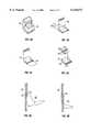
- FIGS. 2A-2Dare frontal views of the attachments for displaying miniature death care merchandise units.
- FIGS. 3A and 3Bare side views of a shelving attachment for displaying miniature death care merchandise units.
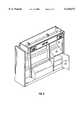
- FIG. 4is an angled front view of a display unit including a cornice assembly secured to the back wall and displaying death care merchandise with full or partial size adornments.
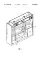
- FIG. 5is a frontal view of one embodiment of the display unit of the invention emphasizing a storage section.
- FIGS. 6 and 6Aare diagrams showing adaptable lighting on the display unit.
- FIG. 7is a view of the top surface of a modular ensemble of the display unit within the invention.
- the present inventionprovides an integrated display system for death care related merchandise.
- the display system of the inventionis principally used in a preview room where selection of death care related merchandise by the decedent's loved ones occurs.
- the display system of the inventionmay be used in death related ceremonial areas such as the viewing room of a funeral home as well as at funeral and memorial services.
- the display system of the inventionis defined by a back wall and side or wing walls.
- One of the principal advantages of the display system of the present inventionis that it allows the display of an extensive line of death care merchandise in a limited space. An entire line of caskets, burial chambers, burial vaults, urns, or other death care merchandise can be shown via miniature replicas of the actual merchandise. Thus, a consumer can look over an entire line of products in the same space that previously only served to show only a few full size products. Thus, great advantages in space are achieved through the use of miniature replicas and through the use of a display system allowing the display of replicas along with full size representations of the optional adornments.
- FIG. 1shows an embodiment of the death care merchandise display system 10 of the invention, principally for use in preview rooms.
- the display system 10comprises a back wall 12 and two side or wing walls 14 and 16. Wing walls 14 and 16 are connected with back wall 12 at the rear section of the wing wall.
- the vertical back wall 12may be removably secured to the rear edges of wing walls 14 and 16.
- FIG. 1shows the preferred embodiment of display system 10 having a floor panel 18.
- floor panel 18is not required and may be omitted.
- One useful effect of floor panel 18is that it serves to strengthen or buttress the entire structure of display system 10.
- display unit 10has subdividers 20 and 22 separating various sections of the display system.
- Back wall panel 12may be divided into discrete subsections depending on the intent of the designer. See, for instance, FIG. 1, where subsections 23, 27 and 29 are used to separate product lines by pricing or quality, or the subsections can be used to display various different articles of death care merchandise.
- the top section of each subsection, such as 21,is preferably used to convey information about the merchandise being displayed.
- subdividers 20 and 22can be constructed to lend support to back wall 12. If floor panel 18 is present, subdividers 20 and 22 can be attached to the top of floor panel 18, or may be guided through floor panel 18. If floor panel 18 is not present, subdividers 20 and 22 could meet the surface display system 10 rests on. In either case, subdividers 20 and 22 can serve to support display system 10 against tipping or warping forces as well as subdivide display system 10 into functionally related areas. Subdividers 20 and 22 are typically crafted to fit into notched grooves of back wall panel 12. In an alternative construction, the back wall may consist of three distinct panels separated by subdividers 20 and 22.
- merchandise display support panels 24a and 24bare added to back wall 12. These merchandise support panels act to reinforce back wall 12 for heavier scale replicas, such as miniature burial chambers made of a dense solid. Merchandise attachment points, such as slots 26a and 26b, serve to support either the death care merchandise itself, or shelving adapted to display the death care merchandise. It should be noted that slots 26 is only one of a number of ways to attach items or shelving to display system 10, and the invention should be construed to include all known means of attaching merchandise or shelving to back wall 12.
- Other known means for removably attaching objectsinclude, e.g., peg-board type attachments, slat wall, tackable surfaces, hook-and-loop fabric (e.g., VELCRO®) attachments, magnetic attachments or other known devices for removably attaching objects to a vertical surface for display of the objects.
- peg-board type attachmentse.g., peg-board type attachments, slat wall, tackable surfaces, hook-and-loop fabric (e.g., VELCRO®) attachments, magnetic attachments or other known devices for removably attaching objects to a vertical surface for display of the objects.
- Shelving unit 50which permits the placement of heavy weights within the display unit comprises back plate 52, shelf surface 54, and shelf attachments 56 and 57. Shelf surface 54 may be angled in relation to back plate 52, as shown in FIG. 2 or may be perpendicular to the back plate. Back plate 52 in particular tends to reduce the natural torque caused within back wall panel 12 thereby increasing its shear strength. As such, it is unnecessary to reinforce back wall panel 12.
- the spatial arrangement of the shelving unit componentsrenders possible the support of multiple units of miniature death care merchandise such as caskets and burial vaults.
- shelf attachment 56may contain receiving member 56b which secures back plate 52 into merchandise attachment point 26.
- flange 56aabuts one side of the outer surface of the lid of the burial vault.
- the miniature burial vaultrests on shelf surface 54 by lip 57.
- shelf surface 54is of solid construction in order to support as much weight on shelf surface 54 as possible.
- shelf surface 54is angled with respect to shelf support 60.
- shelving unit 50could comprise a shell design of shelf surface 54 and shelf support 60, whereby shelf support 60 is attached to back plate 52.
- FIG. 2Ashows death care merchandise 65 displayed on shelving unit 50.
- shelf support 60could comprise movable shelf insert 63.
- movable shelf insertcould be attached to shelving unit 50 via runners comprising the bottom edge of shelf surface 54.
- shelf insert 63is moved into a position of alignment with shelf surface 54.
- shelf insert 63is moved to a position whereby the front edge of shelf insert 63 extends away from shelf 54 and forms a surface where consumers can view death care merchandise in close proximity to the miniature replicas displayed on shelf surface 54.
- Shelf insert 63which is typically an acrylic, may laterally coextend from shelf surface 54 or, alternatively, be angled away from shelf surface 54.
- shelf insert 63is used as an informational aid to inform the observer of the specifics of the vault being displayed.
- FIGS. 3A and 3Bshow how shelving unit 50 may be attached to back wall 12 or merchandise support panel 24.
- Shelf attachment 56is inserted into merchandise attachment point 26.
- shelving unit 50In order to insert shelf attachment 56, shelving unit 50 must be rotated a set angle away from back wall 12. Shelving unit 50 will thus rotate due to gravity to a position as shown in FIG. 3B. Shelf attachment 56 is constructed such that when shelving unit 50 rotates to the displaying position, shelf attachment 56 will be prohibited from exiting attachment point 26 by the construction of back wall 12.
- the shelving unitmay further be attached by other means known in the art.
- Display unit 10 of the inventionmay also contain one or more surfaces, such as 28 and 30, for the display of ornamental objects. As shown in FIG. 4, ornament surfaces 28 and 30 allow for the easy viewing of ornamentation to be attached to the merchandise represented by miniature replica 32.
- shelf insert 62may be extended into the viewing position with numerous ornaments placed on it in close proximity to replica 32. Alternatively, shelf insert 62 could be used for written information regarding the displayed merchandise.
- display unit 10also has cornice 34.
- Cornice 34may contain signage 36 containing line specific or functional specific information about the death care merchandise displayed in display unit 10.
- Cornice 34may be attached to display unit 10 either by attaching it to back wall 12, side wing walls 14 or 16, or both. Many modes of connecting a cornice are known, and detail is not paid to an exact means of attachment.
- the back wall panel and side wing wall panels of the display unit of the inventionare typically plywood but may be fiberwood or other durable material such as a synthetic plastic material as plexiglass or Mylar.
- the back wall panel and side wing wall panelsmay be covered with a fabric-like material or have a textured surface. When so desired, one may removably attach the fabric-like material to the panel allowing the user to select the color and texture.
- the side wing and back wall panels, illustrated in FIGS. 1 and 4are typically 5 to 8 feet tall. In the preferred embodiment they are 7'6" feet tall.
- the cornice 34can conceal an illumination source 280 from the observer.
- the interior of the cornice 34conceals attached illumination source 280 outside the view of a consumer.
- Illumination source 280may be concealed within the vertical interior surfaces 60, 62, and 64 of cornice 34.
- FIG. 6illustrates this feature.
- Exemplary of the illumination sourceare one or more track lights which one may easily manipulate such that the light is directed onto selected merchandise within the display unit. Conventional screws or nuts and bolts can secure track lights to the vertical interior surfaces 60, 62, and 64 of cornice 34.
- Conventional screws or nuts and boltscan secure track lights to the vertical interior surfaces 60, 62, and 64 of cornice 34.
- This illumination systemon side wing walls 14 and 16, or on back wall panel 12 as well.
- the illumination unitcomprises clip 310 and illumination source 320.
- subsections 23, 27 and 29are the subsections closest to back wall 12. In fact, these subsections may actually comprise a portion of back wall 12.
- Merchandise support panel 24a and 24bare separated from subsections 23 and 27, respectively by ledge 25a and 25b.
- the frontal surface of merchandise support panels 24a and 24bextends from the side surface of ledge 25a and 25b.
- Merchandise attachment points 26a and 25bseparate the side of ledge 25a and 25b from the frontal surface of merchandise support panel 24a and 24b.
- Merchandise support panel 24a and 24bare a greater distance from back wall panel 12 than subsections 23 and 27.
- Merchandise support panel 29ais separated from merchandise support panel 24a by means of ledge 27a.
- Ledge 27acauses merchandise support panel 29a to extend a greater distance from back wall panel 12 than merchandise support panel 24a.
- ledge 27ais separated from merchandise support panel 29a by merchandise attachment point 31a.
- ledge 27bdefines the distance which ornament surface 28 extends from merchandise support panel 24b.
- ornament surface 28is a greater distance from back wall panel 12 than merchandise support panel 24b.
- ornament surface 28is angled away from the vertical plane which defines back wall panel 12.
- the display unitcontains one or more modular ensembles, such as modular ensemble 11 or 13.
- modular ensemblesare defined by top surfaces 28 or 30, side wall 70, frontal surface 72 and horizontal bar 74.
- the horizontal bar 74is planar to ledge 27b (for modular ensemble 11) or ledge 25c (for modular ensemble 13).
- top surface 28 or 30is angled away from the vertical plane defined by horizontal bar 74. It should be noted that these surfaces could also be flat, or perpendicular relative to back wall 12 as well.
- Such modular ensemblescould form an integral part of display unit 10 as a "built-in" or be removable from the display unit. Where the ensemble is an integrated part of the display unit it may be secured to the back wall by means of skill in the art, such as by an interlocking French cleat.
- modular ensemble 11may be further modified by having one or more pullout drawers 82.
- the pullout drawercould contain shelving for positioning of a decedent confinement unit. Such shelving may be retractable from the drawer. For aesthetic purposes, it may be desirable for such drawers to contain less aesthetically pleasing units. For instance, when display unit 10 is for the display of burial vaults, it may be desirable that drawer 82 contain concrete liners or other concrete boxes lacking reinforcements.
- top surface 28 of modular ensemble 11is used to display external ornamentation for the death care merchandise, preferably burial vaults.
- top surface 28may be further defined as having top and bottom lips 76 and 78.
- One or more removable panels 80 containing adornment articlesare inserted under lips 76 and 78.
- a second modular ensemble 13may further be the chamber for one or more decedent confinement miniature units such as caskets or burial vaults.
- surface 30is typically used to display information about the merchandise including text, graphics and photographs. In one instance, surface 30 is used to display information about the internment process and the role played by burial vaults in the process.
- ensemble 13may contain one or more shelves 44 for placement of the miniature units. Equipped with door 40, such units may include aesthetically unappealing concrete liners and other merchandise.
- the shelvingmay be adjustable. Preferably, these shelves are attached in a manner by which they may be extended outward when pulled. Most preferably, these shelves are attached by a roller mechanism allowing the contents of shelving 44 to be viewed in an easy manner.
- ensemble 13may be an integral part of the display unit or be free-standing for insertion into the display unit.
- Either ensemble 11 or 13may be modified for placement of a computer or audiovisual aids, surface 28 or 30 serving to hold a monitor, television or other visual aid.
Landscapes
- Display Racks (AREA)
Abstract
Description
Claims (24)
Priority Applications (2)
| Application Number | Priority Date | Filing Date | Title |
|---|---|---|---|
| US09/115,159US6145671A (en) | 1998-07-14 | 1998-07-14 | Integrated display system for death care merchandise |
| CA002274378ACA2274378A1 (en) | 1998-07-14 | 1999-06-14 | Integrated display system for death care merchandise |
Applications Claiming Priority (1)
| Application Number | Priority Date | Filing Date | Title |
|---|---|---|---|
| US09/115,159US6145671A (en) | 1998-07-14 | 1998-07-14 | Integrated display system for death care merchandise |
Publications (1)
| Publication Number | Publication Date |
|---|---|
| US6145671Atrue US6145671A (en) | 2000-11-14 |
Family
ID=22359641
Family Applications (1)
| Application Number | Title | Priority Date | Filing Date |
|---|---|---|---|
| US09/115,159Expired - LifetimeUS6145671A (en) | 1998-07-14 | 1998-07-14 | Integrated display system for death care merchandise |
Country Status (2)
| Country | Link |
|---|---|
| US (1) | US6145671A (en) |
| CA (1) | CA2274378A1 (en) |
Cited By (30)
| Publication number | Priority date | Publication date | Assignee | Title |
|---|---|---|---|---|
| US6467634B1 (en)* | 2000-10-12 | 2002-10-22 | South Brooklyn Casket Co., Inc. | Casket display system |
| US20030000901A1 (en)* | 1997-08-15 | 2003-01-02 | Batesville Services, Inc. | Display for a casket selection and/or viewing room |
| US6585118B2 (en)* | 2000-03-20 | 2003-07-01 | Douglas E. Kellogg | Display system for death care merchandise |
| US20030226811A1 (en)* | 1998-06-04 | 2003-12-11 | Riga Dennis J. | Installation-free death care merchandise display unit |
| US20050000926A1 (en)* | 2003-07-01 | 2005-01-06 | Bowers David Todd | Display for a casket selection room |
| US20050155940A1 (en)* | 2004-01-15 | 2005-07-21 | David Bowers | Display for a casket selection room |
| US20050178190A1 (en)* | 2004-02-13 | 2005-08-18 | Wollenberg Robert H. | High throughput screening methods for lubricating oil compositions |
| US20050241251A1 (en)* | 2004-04-30 | 2005-11-03 | Jane Browe | Display for a casket selection room |
| US20060131253A1 (en)* | 2004-12-22 | 2006-06-22 | Richardson Joseph T | Modular display apparatus |
| USD525807S1 (en) | 2000-10-12 | 2006-08-01 | Milso Industries, Inc. | Display for casket features |
| WO2007110593A1 (en)* | 2006-03-24 | 2007-10-04 | Chapman Research Limited | Merchandising |
| US20080099418A1 (en)* | 2006-11-01 | 2008-05-01 | Andy Wells | Product display |
| US20080236053A1 (en)* | 2007-03-29 | 2008-10-02 | Jerry David Adams | Room display for funerary products |
| US20090014396A1 (en)* | 2007-07-13 | 2009-01-15 | Batesville Services, Inc. | Method of mounting casket portion to display |
| US20090107940A1 (en)* | 2007-10-25 | 2009-04-30 | Christopher Norman | Stock wing merchandise display |
| US20110000955A1 (en)* | 2009-05-15 | 2011-01-06 | Menasha Corporation | Slider Power-Wing Box |
| US20110049072A1 (en)* | 2009-09-02 | 2011-03-03 | Menasha Corporation | Corrugated Shelving Display System with Two-Piece Shelves |
| US8141713B2 (en) | 2009-10-01 | 2012-03-27 | Menasha Corporation | Container with pull-out compartments |
| US20120228240A1 (en)* | 2011-03-08 | 2012-09-13 | T-Ink, Llc | Intelligent Display And Fixture System |
| US8267363B2 (en) | 2007-10-09 | 2012-09-18 | Waterloo Industries, Inc. | Wall storage mounting arrangements |
| US8827078B2 (en) | 2011-04-27 | 2014-09-09 | Jana Doemel | Container with kick-back |
| US8863417B2 (en) | 2011-10-25 | 2014-10-21 | Menasha Corporation | End stand display system and side saddle display and product holder |
| US8978280B2 (en) | 2012-03-12 | 2015-03-17 | Menasha Corporation | Arched display |
| US9009997B1 (en)* | 2014-03-04 | 2015-04-21 | Spanx, Inc. | Display fixture |
| US9474389B2 (en) | 2012-02-20 | 2016-10-25 | Menasha Corporation | Corrugated hutch |
| US10524589B2 (en) | 2017-06-23 | 2020-01-07 | Menasha Corporation | Ship flat hutch with auto bottom |
| US10568422B2 (en) | 2016-04-15 | 2020-02-25 | Menasha Corporation | Corrugated hutch |
| US11019943B2 (en) | 2019-03-15 | 2021-06-01 | Menasha Corporation | Full wing display |
| US11154145B1 (en) | 2020-07-29 | 2021-10-26 | Menasha Corporation | Corrugated shelving display with two-piece shelves |
| US11751702B2 (en) | 2021-05-25 | 2023-09-12 | Menasha Corporation | Shelving display |
Citations (15)
| Publication number | Priority date | Publication date | Assignee | Title |
|---|---|---|---|---|
| US899052A (en)* | 1908-05-05 | 1908-09-22 | Dudley W Imus | Show-case for displaying pickles and the like. |
| US1146488A (en)* | 1914-08-06 | 1915-07-13 | Mayer Finkelstein | Folding display-rack. |
| US1713908A (en)* | 1927-12-31 | 1929-05-21 | Lane Moses Henry | Display stand |
| US2326493A (en)* | 1940-11-04 | 1943-08-10 | Milwaukee Lace Paper Co | Display stand |
| US3828937A (en)* | 1972-08-09 | 1974-08-13 | G Nash | Adjustable pole support system |
| US3874753A (en)* | 1972-07-21 | 1975-04-01 | Iwate Fuji Sangyo Kk | Unit furniture |
| US4082388A (en)* | 1976-11-17 | 1978-04-04 | Goeglein Roy F | Collapsible display booth |
| US4526110A (en)* | 1982-10-06 | 1985-07-02 | Leggett & Platt, Incorporated | Canopy for an upright display |
| US4540222A (en)* | 1983-02-28 | 1985-09-10 | Burrell Alfred A | Cabinet structure for storing, displaying and indexing |
| US4716841A (en)* | 1982-09-07 | 1988-01-05 | The Mead Corporation | Shelving unit |
| US5199775A (en)* | 1990-11-23 | 1993-04-06 | The Corporate Communications Group, Inc. | Modular exhibitry unit |
| US5405017A (en)* | 1993-03-02 | 1995-04-11 | Batesville Casket Company, Inc. | Modular casket display system |
| US5787626A (en)* | 1996-04-30 | 1998-08-04 | Batesville Casket Company, Inc. | Funeral product display case |
| US5797499A (en)* | 1996-09-10 | 1998-08-25 | South Brooklyn Casket Co., Inc. | Casket display system and construction method |
| US5901862A (en)* | 1997-01-24 | 1999-05-11 | The York Group, Inc. | Death care merchandise display unit |
- 1998
- 1998-07-14USUS09/115,159patent/US6145671A/ennot_activeExpired - Lifetime
- 1999
- 1999-06-14CACA002274378Apatent/CA2274378A1/ennot_activeAbandoned
Patent Citations (16)
| Publication number | Priority date | Publication date | Assignee | Title |
|---|---|---|---|---|
| US899052A (en)* | 1908-05-05 | 1908-09-22 | Dudley W Imus | Show-case for displaying pickles and the like. |
| US1146488A (en)* | 1914-08-06 | 1915-07-13 | Mayer Finkelstein | Folding display-rack. |
| US1713908A (en)* | 1927-12-31 | 1929-05-21 | Lane Moses Henry | Display stand |
| US2326493A (en)* | 1940-11-04 | 1943-08-10 | Milwaukee Lace Paper Co | Display stand |
| US3874753A (en)* | 1972-07-21 | 1975-04-01 | Iwate Fuji Sangyo Kk | Unit furniture |
| US3828937A (en)* | 1972-08-09 | 1974-08-13 | G Nash | Adjustable pole support system |
| US4082388A (en)* | 1976-11-17 | 1978-04-04 | Goeglein Roy F | Collapsible display booth |
| US4716841A (en)* | 1982-09-07 | 1988-01-05 | The Mead Corporation | Shelving unit |
| US4526110A (en)* | 1982-10-06 | 1985-07-02 | Leggett & Platt, Incorporated | Canopy for an upright display |
| US4540222A (en)* | 1983-02-28 | 1985-09-10 | Burrell Alfred A | Cabinet structure for storing, displaying and indexing |
| US5199775A (en)* | 1990-11-23 | 1993-04-06 | The Corporate Communications Group, Inc. | Modular exhibitry unit |
| US5405017A (en)* | 1993-03-02 | 1995-04-11 | Batesville Casket Company, Inc. | Modular casket display system |
| US5848498A (en)* | 1993-03-02 | 1998-12-15 | Batesville Casket Company, Inc. | Modular casket display system |
| US5787626A (en)* | 1996-04-30 | 1998-08-04 | Batesville Casket Company, Inc. | Funeral product display case |
| US5797499A (en)* | 1996-09-10 | 1998-08-25 | South Brooklyn Casket Co., Inc. | Casket display system and construction method |
| US5901862A (en)* | 1997-01-24 | 1999-05-11 | The York Group, Inc. | Death care merchandise display unit |
Cited By (61)
| Publication number | Priority date | Publication date | Assignee | Title |
|---|---|---|---|---|
| US7036196B2 (en)* | 1997-08-15 | 2006-05-02 | Batesville Services, Inc. | Display for a casket selection and/or viewing room |
| US20030000901A1 (en)* | 1997-08-15 | 2003-01-02 | Batesville Services, Inc. | Display for a casket selection and/or viewing room |
| US6681510B1 (en)* | 1997-08-15 | 2004-01-27 | Batesville Services, Inc. | Display for a casket selection and/or viewing room |
| US20030226811A1 (en)* | 1998-06-04 | 2003-12-11 | Riga Dennis J. | Installation-free death care merchandise display unit |
| US6585118B2 (en)* | 2000-03-20 | 2003-07-01 | Douglas E. Kellogg | Display system for death care merchandise |
| US6467634B1 (en)* | 2000-10-12 | 2002-10-22 | South Brooklyn Casket Co., Inc. | Casket display system |
| US7191906B1 (en) | 2000-10-12 | 2007-03-20 | Matthews Resources, Inc. | Casket display system |
| USD525807S1 (en) | 2000-10-12 | 2006-08-01 | Milso Industries, Inc. | Display for casket features |
| US20050000926A1 (en)* | 2003-07-01 | 2005-01-06 | Bowers David Todd | Display for a casket selection room |
| US20070227054A1 (en)* | 2004-01-15 | 2007-10-04 | Batesville Services, Inc. | Display for a casket selection room |
| US8091713B2 (en) | 2004-01-15 | 2012-01-10 | Batesville Services, Inc. | Display for a casket selection room |
| US7891505B2 (en)* | 2004-01-15 | 2011-02-22 | Batesville Services, Inc. | Display for a casket selection room |
| US7520395B2 (en)* | 2004-01-15 | 2009-04-21 | Batesville Services, Inc. | Display for a casket selection room |
| US20050155940A1 (en)* | 2004-01-15 | 2005-07-21 | David Bowers | Display for a casket selection room |
| US20110068068A1 (en)* | 2004-01-15 | 2011-03-24 | Batesville Services, Inc. | Display For A Casket Selection Room |
| US20090243449A1 (en)* | 2004-01-15 | 2009-10-01 | Batesville Services, Inc. | Display for a casket selection room |
| US20050178190A1 (en)* | 2004-02-13 | 2005-08-18 | Wollenberg Robert H. | High throughput screening methods for lubricating oil compositions |
| US8499502B2 (en) | 2004-04-30 | 2013-08-06 | Batesville Services, Inc. | Display for a casket selection room |
| US20050241251A1 (en)* | 2004-04-30 | 2005-11-03 | Jane Browe | Display for a casket selection room |
| US7308987B2 (en)* | 2004-12-22 | 2007-12-18 | Behr Process Corporation | Modular display apparatus |
| US20060131253A1 (en)* | 2004-12-22 | 2006-06-22 | Richardson Joseph T | Modular display apparatus |
| US20060152924A1 (en)* | 2004-12-22 | 2006-07-13 | Richardson Joseph T | Modular display with irrigation feature |
| US7604132B2 (en) | 2004-12-22 | 2009-10-20 | Behr Process Corporation | Modular display with irrigation feature |
| GB2436393B (en)* | 2006-03-24 | 2011-03-16 | Chapman Res Ltd | Merchandising |
| US20090210359A1 (en)* | 2006-03-24 | 2009-08-20 | Chapman Research Limited | Merchandising |
| WO2007110593A1 (en)* | 2006-03-24 | 2007-10-04 | Chapman Research Limited | Merchandising |
| US20080099418A1 (en)* | 2006-11-01 | 2008-05-01 | Andy Wells | Product display |
| US7954653B2 (en)* | 2007-03-29 | 2011-06-07 | Batesville Services, Inc. | Room display for funerary products |
| US20080236053A1 (en)* | 2007-03-29 | 2008-10-02 | Jerry David Adams | Room display for funerary products |
| US20090014396A1 (en)* | 2007-07-13 | 2009-01-15 | Batesville Services, Inc. | Method of mounting casket portion to display |
| US20110011815A1 (en)* | 2007-07-13 | 2011-01-20 | Batesville Services, Inc. | Method of mounting casket to display |
| US7992727B2 (en) | 2007-07-13 | 2011-08-09 | Batesville Services, Inc. | Method of mounting casket to display |
| US7798337B2 (en) | 2007-07-13 | 2010-09-21 | Batesville Services, Inc. | Method of mounting casket portion to display |
| US8267363B2 (en) | 2007-10-09 | 2012-09-18 | Waterloo Industries, Inc. | Wall storage mounting arrangements |
| US8528871B2 (en) | 2007-10-09 | 2013-09-10 | Waterloo Industries, Inc. | Wall storage mounting arrangements |
| US20090107940A1 (en)* | 2007-10-25 | 2009-04-30 | Christopher Norman | Stock wing merchandise display |
| US20110000955A1 (en)* | 2009-05-15 | 2011-01-06 | Menasha Corporation | Slider Power-Wing Box |
| US8857633B2 (en) | 2009-09-02 | 2014-10-14 | Menasha Corporation | Corrugated shelving display system with two-piece shelves |
| US8485370B2 (en) | 2009-09-02 | 2013-07-16 | Menasha Corporation | Corrugated shelving display system with two-piece shelves |
| US20110049072A1 (en)* | 2009-09-02 | 2011-03-03 | Menasha Corporation | Corrugated Shelving Display System with Two-Piece Shelves |
| US8141713B2 (en) | 2009-10-01 | 2012-03-27 | Menasha Corporation | Container with pull-out compartments |
| US20120228240A1 (en)* | 2011-03-08 | 2012-09-13 | T-Ink, Llc | Intelligent Display And Fixture System |
| US8827078B2 (en) | 2011-04-27 | 2014-09-09 | Jana Doemel | Container with kick-back |
| US8863417B2 (en) | 2011-10-25 | 2014-10-21 | Menasha Corporation | End stand display system and side saddle display and product holder |
| US9474389B2 (en) | 2012-02-20 | 2016-10-25 | Menasha Corporation | Corrugated hutch |
| US8978280B2 (en) | 2012-03-12 | 2015-03-17 | Menasha Corporation | Arched display |
| US9009997B1 (en)* | 2014-03-04 | 2015-04-21 | Spanx, Inc. | Display fixture |
| US20150255011A1 (en)* | 2014-03-04 | 2015-09-10 | Spanx, Inc. | Display Fixture |
| US11478076B2 (en) | 2016-04-15 | 2022-10-25 | Menasha Corporation | Corrugated hutch |
| US10568422B2 (en) | 2016-04-15 | 2020-02-25 | Menasha Corporation | Corrugated hutch |
| US10973317B2 (en) | 2016-04-15 | 2021-04-13 | Menasha Corporation | Corrugated hutch |
| US11832720B2 (en) | 2016-04-15 | 2023-12-05 | Menasha Corporation | Corrugated hutch |
| US10524589B2 (en) | 2017-06-23 | 2020-01-07 | Menasha Corporation | Ship flat hutch with auto bottom |
| US11019943B2 (en) | 2019-03-15 | 2021-06-01 | Menasha Corporation | Full wing display |
| US11832741B2 (en) | 2019-03-15 | 2023-12-05 | Menasha Corporation | Full wing display |
| US20240225313A9 (en)* | 2019-03-15 | 2024-07-11 | Menasha Corporation | Full wing display |
| US12213604B2 (en)* | 2019-03-15 | 2025-02-04 | Menasha Corporation | Full wing display |
| US11154145B1 (en) | 2020-07-29 | 2021-10-26 | Menasha Corporation | Corrugated shelving display with two-piece shelves |
| US11517129B2 (en) | 2020-07-29 | 2022-12-06 | Menasha Corporation | Corrugated shelving display with two-piece shelves |
| US11805926B2 (en) | 2020-07-29 | 2023-11-07 | Menasha Corporation | Corrugated shelving display with two-piece shelves |
| US11751702B2 (en) | 2021-05-25 | 2023-09-12 | Menasha Corporation | Shelving display |
Also Published As
| Publication number | Publication date |
|---|---|
| CA2274378A1 (en) | 2000-01-14 |
Similar Documents
| Publication | Publication Date | Title |
|---|---|---|
| US6145671A (en) | Integrated display system for death care merchandise | |
| US6161705A (en) | Death care merchandise display unit | |
| CA2332691C (en) | Death care merchandising system | |
| US5709441A (en) | Cremation urn display pedestal | |
| US6070741A (en) | Memorial death care merchandise display unit and method for displaying death care merchandise | |
| US8419140B2 (en) | Chambered cremation URN memorial with attached or integrated electronic imaging device | |
| WO1999008577A1 (en) | Display for a casket selection and/or viewing room | |
| US6585118B2 (en) | Display system for death care merchandise | |
| US7954653B2 (en) | Room display for funerary products | |
| US8505753B2 (en) | Display apparatus and method | |
| US6276034B1 (en) | Slat wall death care merchandise display unit with category delineator | |
| US6105793A (en) | Death care merchandise display unit | |
| US5659991A (en) | Picture frame | |
| US5960966A (en) | Modular walls for death care merchandise display unit | |
| US4941714A (en) | Jewelry display and servicing kiosk | |
| US7107222B1 (en) | Death care merchandising system | |
| US7895783B1 (en) | Multi-media display system | |
| US20080099418A1 (en) | Product display | |
| US7793792B2 (en) | Death care merchandise display system | |
| MXPA99006551A (en) | Integrated exhibitor system for goods dedicated to defunc | |
| CA2285874C (en) | Death care merchandise display unit | |
| CA2227850C (en) | Modular walls for death care merchandise display unit | |
| CA2272117A1 (en) | Installation-free death care display unit | |
| MXPA99011193A (en) | Memorial death care merchandise display unit and method for displaying death care merchandise | |
| MXPA98000712A (en) | Mortuor merchandise exhibition unit |
Legal Events
| Date | Code | Title | Description |
|---|---|---|---|
| AS | Assignment | Owner name:YORK GROUP, INC., THE, TEXAS Free format text:ASSIGNMENT OF ASSIGNORS INTEREST;ASSIGNORS:RIGA, DENNIS J.;MONSERRATE, MARTA;REEL/FRAME:009318/0876 Effective date:19970714 | |
| AS | Assignment | Owner name:ABN AMRO BANK N.V., AS COLLATERAL AGENT, TEXAS Free format text:SECURITY INTEREST;ASSIGNOR:YORK GROUP, INC., THE;REEL/FRAME:010506/0027 Effective date:19990812 | |
| STCF | Information on status: patent grant | Free format text:PATENTED CASE | |
| AS | Assignment | Owner name:YORK GROUP, INC., THE, TEXAS Free format text:SECURITY AGREEMENT-RELEASE;ASSIGNOR:ABN AMRO BANK N.V.;REEL/FRAME:012475/0841 Effective date:20010524 | |
| FPAY | Fee payment | Year of fee payment:4 | |
| AS | Assignment | Owner name:MATTHEWS RESOURCES, INC., DELAWARE Free format text:ASSIGNMENT OF ASSIGNORS INTEREST;ASSIGNOR:THE YORK GROUP, INC.;REEL/FRAME:017946/0052 Effective date:20011203 | |
| REMI | Maintenance fee reminder mailed | ||
| FPAY | Fee payment | Year of fee payment:8 | |
| SULP | Surcharge for late payment | Year of fee payment:7 | |
| FPAY | Fee payment | Year of fee payment:12 | |
| AS | Assignment | Owner name:MATTHEWS INTERNATIONAL CORPORATION, PENNSYLVANIA Free format text:ASSIGNMENT OF ASSIGNORS INTEREST;ASSIGNOR:MATTHEWS RESOURCES, INC.;REEL/FRAME:044707/0952 Effective date:20170929 |