US6145143A - Patient support systems with layered fluid support mediums - Google Patents
Patient support systems with layered fluid support mediumsDownload PDFInfo
- Publication number
- US6145143A US6145143AUS09/325,532US32553299AUS6145143AUS 6145143 AUS6145143 AUS 6145143AUS 32553299 AUS32553299 AUS 32553299AUS 6145143 AUS6145143 AUS 6145143A
- Authority
- US
- United States
- Prior art keywords
- layer
- patient support
- inflatable
- sheet
- fluid
- Prior art date
- Legal status (The legal status is an assumption and is not a legal conclusion. Google has not performed a legal analysis and makes no representation as to the accuracy of the status listed.)
- Expired - Lifetime
Links
Images


Classifications
- A—HUMAN NECESSITIES
- A61—MEDICAL OR VETERINARY SCIENCE; HYGIENE
- A61G—TRANSPORT, PERSONAL CONVEYANCES, OR ACCOMMODATION SPECIALLY ADAPTED FOR PATIENTS OR DISABLED PERSONS; OPERATING TABLES OR CHAIRS; CHAIRS FOR DENTISTRY; FUNERAL DEVICES
- A61G7/00—Beds specially adapted for nursing; Devices for lifting patients or disabled persons
- A61G7/05—Parts, details or accessories of beds
- A61G7/057—Arrangements for preventing bed-sores or for supporting patients with burns, e.g. mattresses specially adapted therefor
- A61G7/05715—Arrangements for preventing bed-sores or for supporting patients with burns, e.g. mattresses specially adapted therefor with modular blocks, or inserts, with layers of different material
- A—HUMAN NECESSITIES
- A61—MEDICAL OR VETERINARY SCIENCE; HYGIENE
- A61G—TRANSPORT, PERSONAL CONVEYANCES, OR ACCOMMODATION SPECIALLY ADAPTED FOR PATIENTS OR DISABLED PERSONS; OPERATING TABLES OR CHAIRS; CHAIRS FOR DENTISTRY; FUNERAL DEVICES
- A61G7/00—Beds specially adapted for nursing; Devices for lifting patients or disabled persons
- A61G7/05—Parts, details or accessories of beds
- A61G7/057—Arrangements for preventing bed-sores or for supporting patients with burns, e.g. mattresses specially adapted therefor
- A61G7/05769—Arrangements for preventing bed-sores or for supporting patients with burns, e.g. mattresses specially adapted therefor with inflatable chambers
- A—HUMAN NECESSITIES
- A61—MEDICAL OR VETERINARY SCIENCE; HYGIENE
- A61G—TRANSPORT, PERSONAL CONVEYANCES, OR ACCOMMODATION SPECIALLY ADAPTED FOR PATIENTS OR DISABLED PERSONS; OPERATING TABLES OR CHAIRS; CHAIRS FOR DENTISTRY; FUNERAL DEVICES
- A61G7/00—Beds specially adapted for nursing; Devices for lifting patients or disabled persons
- A61G7/05—Parts, details or accessories of beds
- A61G7/057—Arrangements for preventing bed-sores or for supporting patients with burns, e.g. mattresses specially adapted therefor
- A61G7/05784—Arrangements for preventing bed-sores or for supporting patients with burns, e.g. mattresses specially adapted therefor with ventilating means, e.g. mattress or cushion with ventilating holes or ventilators
- A—HUMAN NECESSITIES
- A61—MEDICAL OR VETERINARY SCIENCE; HYGIENE
- A61G—TRANSPORT, PERSONAL CONVEYANCES, OR ACCOMMODATION SPECIALLY ADAPTED FOR PATIENTS OR DISABLED PERSONS; OPERATING TABLES OR CHAIRS; CHAIRS FOR DENTISTRY; FUNERAL DEVICES
- A61G2210/00—Devices for specific treatment or diagnosis
- A61G2210/70—Devices for specific treatment or diagnosis for cooling
- A—HUMAN NECESSITIES
- A61—MEDICAL OR VETERINARY SCIENCE; HYGIENE
- A61G—TRANSPORT, PERSONAL CONVEYANCES, OR ACCOMMODATION SPECIALLY ADAPTED FOR PATIENTS OR DISABLED PERSONS; OPERATING TABLES OR CHAIRS; CHAIRS FOR DENTISTRY; FUNERAL DEVICES
- A61G2210/00—Devices for specific treatment or diagnosis
- A61G2210/90—Devices for specific treatment or diagnosis for heating
Definitions
- This inventionrelates generally to a patient support system for reducing and preventing the development of decubitus ulcers or bed sores in patients. More specifically, the present invention relates to a patient support system comprising multiple support layers whereby each layer is operable to reduce the lateral and normal pressures and forces which can cause such bed sores on a patient.
- the present inventionrelates to a low-air-loss patient support system including an anti-shear cover layer overlapping a fluid bladder or pouch layer which is positioned in overlying relation or integral to the upper surface of a low-air-loss bed.
- bed soresare a frequent medical complication in patients suffering from trauma that can lead to the deterioration of the patient's skin and underlying tissue.
- burn victimsare extremely susceptible to both the development of bed sores and continued exasperation of existing wounds.
- Bed soresare also frequently found to occur at the bony protuberances along a patient's body. More specifically, when a patient lies supinely against a support surface, most of the patient's weight is supported by the bony protuberances located along such areas as the hip, the scapula, the spinal area, heels and occipital region of the head.
- U.S. Pat. No. 5,511,260discloses a mattress pad comprising a film layer positioned atop a fluid bladder layer supported by foam base layer. Though this particular mattress pad may effectively address the normal forces and pressures experienced by a patient's body resting atop its support surface, it fails to adequately address the problem of moisture accumulation between the patient and the patient support surface. As discussed above, moisture accumulation is a major factor in the development of bed sores. Likewise, U.S. Pat. No.
- 5,044,029discloses a low-air-loss bed capable of uniformly distributing the supporting pressure points along the body surface, thereby reducing the normal pressures and forces experienced at the critical bony protuberances.
- This patient support alonedoes not adequately address the lateral shear forces experienced by the patient as he or she is moved across the support surface.
- no single prior artprovides protection against the wide range of bed sore causing factors. With this in mind, the present invention was developed.
- the present inventionrepresents an improved patient support system over the prior art for the prevention of bed sores in patients.
- this inventionis specially designed to either reduce or prevent a greater number of bed sore causing factors than previously addressed by the prior art.
- the present inventionprovides numerous advantages to bedridden patients heretofore found only associated with separate and distinctly different patient support systems. These advantages include its ability to adjust the positioning and immobilization of the patient as desired by adjusting the air pressure within individual chambers or zones of chambers, its ability to dramatically reduce undesirable lateral shearing forces between the patient and the support surface, its ability to wick moisture away from the patient's body, and its ability to further reduce normal pressures and forces at specific locations along the patient's body.
- an object of the present inventionto provide a patient support system comprising an inflatable patient support, a fluid bladder or pouch layer positioned in overlying relation to the upper surface of the inflatable patient support, means for securing the fluid bladder layer to the upper surface of the inflatable patient support, an anti-shear cover layer placed in overlying relation to the upper surface of the fluid bladder layer and inflatable patient support, means for securing the anti-shear cover layer to the fluid bladder layer and/or inflatable patient support, and means for facilitating substantial sliding movement between the top and bottom layers of the anti-shear cover layer thereby reducing the lateral shear forces experienced by a patient supported thereon.
- Another object of the present inventionis to provide a fluid bladder layer in which the fluid bladders or pouches are secured atop an inflatable patient support in configuration that is customized to the pressure points along a particular patient's body.
- Another object of the present inventionis to provide a fluid bladder layer assembled with releasable discrete fluid bladders or pouches so as to allow such bladders or pouches to be removed or replaced as may be required.
- Another object of the present inventionis to provide an inflatable patient support having attachment means for securing at least one fluid bladder or pouch to the upper surface of the inflatable patient support to form a fluid bladder layer.
- Another object of the present inventionis to provide an inflatable patient support having at least a portion of which is made of a moisture vapor permeable material.
- Another object of the present inventionis to provide an anti-shear cover layer comprised of a top layer bounded to a bottom layer to form an internal chamber for containing a lubricant that enhances the relative sliding movement between the adjacent contacting surfaces of the top layer and bottom layer and, thus, allows a patient resting atop the top layer to slide relative to the bottom layer thereby reducing the frictional force normally experienced by a patient moving across a patient support surface.
- Another object of the present inventionis to provide an anti-shear cover layer that can be quickly and easily removed to allow for convenient maintenance to the underlying fluid bladder layer or inflatable patient support as may be required.
- Another object of the present inventionis to provide a means for regulating the temperature of the fluid contained within the fluid bladder layer and, thereby, allow the operator or patient to effectively maintain a desired patient body surface temperature.
- a patient support systemcomprising an anti-shear cover layer for overlapping a fluid bladder layer positioned atop an inflatable patient support.
- the anti-shear cover layeris comprised of a top fabric layer forming a patient support surface and a bottom fabric layer positioned substantially adjacent to the top surface of a fluid bladder support layer.
- the peripheral edge of the top fabric layeris secured to the peripheral edge of the underlying bottom fabric layer which forms a chamber between the top and bottom layers, into which a lubricant material is disposed to enhance slippage between the contacting surfaces of the two layers.
- the bottom surface of the bottom layeris secured to the fluid bladder layer by connecting means and/or frictional forces and is, therefore, generally held in a fixed position.
- the top fabric layeris only secured about its peripheral edge to the bottom fabric layer and is, therefore, able to slide relative to the bottom fabric layer.
- a patient resting atop the anti-shear cover layerexperiences reduced frictional and lateral shear forces as the top patient support layer, through the action of the lubricant material, is able to slide relative to the bottom layer which is relatively affixed to the top surface of either the fluid bladder layer or inflatable air mattress.
- the middle section of the top fabric layercorresponding to the torso section of the patient, can be attached to the bottom fabric layer.
- the patient's upper and lower bodyare able to slide relative to the underlying bottom layer of the anti-shear cover layer.
- At least a portion of the anti-shear cover layeris constructed of a water vapor permeable material to help eliminate moisture from between the patient's body and the contacting surface of the top layer.
- a fluid bladder layercomprising a plurality of discrete fluid bladders or pouches for reducing the normal pressures and forces experienced by a patient resting atop the patient support surface.
- the fluid bladder layeris specially designed to be positioned in overlying relation to the upper surface of an inflatable patient support, and is provided with means to releasably secure the fluid bladder layer to the inflatable patient support.
- the fluid bladder layerincludes one or more discrete fluid pouches releasably or integrally secured to a fabric sheet at positions on the fabric sheet which correspond to increased pressure points on the patient's body, such as the heel, buttocks, or scapula.
- the fluid pouch retaining fabric sheetis draped over the underlying inflatable patient support, thereby arranging the fluid pouches on the upper surface of the inflatable patient support at preferred positions corresponding to areas on the patient's body which may be susceptible to the development of bed sores.
- Using individually detachable fluid pouchesenables the fluid bladder layer to be customized to best suit the characteristics of a particular bed user.
- Portions of the fabric sheetare constructed of a water vapor permeable material to promote the elimination of moisture from the patient's body.
- a fluid bladder layercomprising a plurality of discrete fluid pouches operably secured to specific positions atop an inflatable patient support. More specifically, the fluid bladder layer is formed by securing one or more discrete fluid pouches directly to the surface of the inflatable patient support at positions which correspond to areas on the patient's body that are susceptible to bed sore development. Alternatively, a fluid bladder layer is provided as an integral component of an inflatable patient support. In this way, the inflatable air chamber or air chambers comprising an inflatable patient support are assembled having fluid pouches integrally secured substantially adjacent to the upper surface of the inflatable patient support.
- a low-air-loss bedcomprising at least one gas permeable air chamber mounted on a base frame, and placed in fluid communication with a source of gas.
- the air chamber or chambersare in communication with a gas source operable to change the amount of gas delivered to the air chamber or chambers, thereby varying the amount of support provided for each portion of the patient.
- the air chamber or chambersmay be constructed of a first material which is relatively impermeable to gas and a second material which is gas permeable, the sides and bottom of each chamber being preferably constructed of the second material.
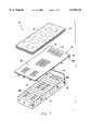
- FIG. 1is an exploded view of the presently preferred embodiment of the fluid air patient support system of the present invention.
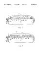
- FIG. 3is a vertical sectional view similar to FIG. 2, except the fluid pouches are shown releasably secured to the upper surface of the fabric sheet component of the fluid bladder layer.
- FIG. 4shows an alternate embodiment for attaching discrete fluid pouches to an underlying inflatable air cushion for forming a fluid bladder layer.
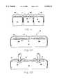
- FIG. 5is a cross-sectional view showing another alternate embodiment for releasably securing fluid pouches to underlying inflatable air cushions which form an inflatable air mattress.
- FIG. 6is a vertical sectional view taken through the anti-shear cover layer overlaying the alternate fluid bladder layer shown in FIG. 5, and illustrating the operation of the fluid bladder layer and inflatable air cushion to support a patient's bony protuberance (i.e. heel).
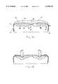
- FIG. 8is a vertical sectional view of the alternate embodiment shown in FIG. 7, and illustrating the operation of the fluid bladder layer and inflatable air cushion to support a patient's bony protuberance.
- FIG. 9is a cross-sectional view of the alternate embodiment shown in FIG. 7.
- FIG. 10is an exploded view of an anti-shear top cover layer illustrating the top fabric layer positioned above the bottom fabric layer and the fabric sleeve used to secure the anti-shear cover layer to an underlying inflatable air mattress.
- FIG. 11shows a perspective view of the anti-shear top cover layer.
- FIG. 12is an exploded view of the fluid pouch and the VELCRO connector strips illustrated in FIG. 4.
- FIGS. 1 through 12at least one embodiment of the present invention may be appreciated to prevent the development of bed sores in a patient confined to a bed for an indefinite period of time.
- a patient support system 10comprising multiple patient support layers including an anti-shear cover layer 11 overlaying a fluid bladder layer 12 positioned in overlying relation to an inflatable air mattress 13, or other inflatable patient support.
- the anti-shear cover layer 11 and fluid bladder layer 12are releasably secured atop the inflatable air mattress 13 to facilitate convenient removal for cleaning, adjustment or other required maintenance.
- the inflatable air mattress 13 of the present inventionis preferably a plurality of joined inflatable air cushions 14 to allow for better pressure control in each of the air cushions 14 so that the inflatable cushions 14 can be collectively adjusted to better accommodate patients of varying heights and weight.
- the pressure within each inflatable air cushion 14can be adjusted so as to allow the patient to sink into the inflatable mattress 13 without bottoming out on the mattress support surface (not shown).
- the normal pressure and force imposed against particular pressure points on the patient's skinis distributed over a greater skin surface area.
- Each inflatable air cushion 14is preferably constructed of a fabric material which is permeable to water vapor, but impermeable to water and other liquids.
- THERAKAIRcommercially available from Kinetics Concepts, Inc., of San Antonio, Tex.
- KCIKinetics Concepts, Inc.
- the THERAKAIR bedis described in substantial detail in U.S. Pat. No. 5,267,364, and incorporated herein by this reference. It should be understood by those skilled in the art, however, that alternative inflatable air mattress systems, configurations, and construction can be utilized without departing from the scope of the present invention.
- a preferred fluid bladder layer 12comprises one or more fluid pouches 16 integrally or releasably secured to a full length fabric sheet 15 which is placed in overlying relation to the entire length of the inflatable air mattress 13.
- Providing fluid pouches 16 which are releasably secured to the surface of the fabric sheet 15enables a bed user to customize a fluid bladder layer 12 to the needs of a particular patient.
- the fluid pouches 16can be assembled on the fabric sheet 15 so as to form an essentially continuous layer of fluid pouches 16 overlying the inflatable air mattress 13, or overlay only a portion of the inflatable air mattress 13.
- a particular fluid pouch 16can be aligned and secured to the surface of the fabric sheet 15 at a specific position so that when the fabric sheet 15 is placed over the inflatable air mattress 13 that fluid pouch 16 is positioned at a patient's most susceptible area or areas of bed sore development. These areas may correspond with trauma sites or the pressure points associated with the bony protuberances of a patient such as the heels, the buttocks, the scapula, and the occipital region of the head.
- the anti-shear cover layer 11forms a patient support surface 18 and is, as will be explained in more detail below, specially designed to reduce any undesirable lateral shear forces experienced by the patient as he or she moves or is moved laterally across the patient support surface 18.
- a preferred fluid bladder layer 12comprises one or more fluid pouches 16 integrally attached (as shown in FIG. 2) or releasably secured to a fabric sheet 15 (as shown in FIG. 3).
- the fluid bladder layer 12can be formed by integrally attaching one or more fluid pouches 16 to the upper surface 17 of an inflatable air cushion 14 (FIG. 8), as will be discussed in more detail below.
- the fluid bladder layer 12is shown overlapped by the anti-shear cover layer 11, and positioned in overlying relation to the upper surface 17 of an inflatable air cushion 14.
- the fabric sheet 15is constructed of a low-air-loss fabric material which is permeable to water vapor, but impermeable to water and other liquids.
- a low-air-loss fabric materialis the fabric sold under the trademark "GORE-TEX" from W. L. Gore & Associates, Inc. of Elkton, Md.
- GORE-TEXW. L. Gore & Associates, Inc. of Elkton, Md.
- Such low-air-loss materialhas very little air permeability yet has a moisture vapor transmission rate in excess of 4700 g/m 2 /24 hours. This preferred material allows any moisture that may accumulate to be drawn through the vapor permeable fabric sheet 15 and away from the patient.
- the fabric sheet 15is constructed having an area bordered by a peripheral edge 36 which is oversized relative to the upper surface 17 of the inflatable air mattress 13. This preferred oversizing allows the peripheral edge 36 of the fabric sheet 15 to extend downward and adjacent to the side wall 35 of the inflatable air mattress 13. Oversizing the fabric sheet 15 provides a fluid bladder layer 12 with a relatively loose and bunched configuration atop the upper surface 17 of the air mattress 13. As will be understood by those skilled in the art, oversizing the fabric sheet 15 is necessary to prevent the fluid bladder layer 12 and/or fabric sheet 15 from pulling taut when a patient is placed onto the patient support system 10 and, thus, allows the patient to sink into the inflatable air mattress 13. Oversizing the fabric sheet 15 further prevents the exertion of pulling forces upon the attachments connecting the fabric sheet 15 to the side wall 35 of the inflatable air mattress 13, which could potentially cause damage to the inflatable air mattress 13, resulting in an air leak.
- a preferred fluid bladder layer 12is held atop the inflatable air mattress 13 using a connecting means 20a which is attached to a plurality of fabric strips 21 secured to and extending perpendicular from the perimeter 36 of the fabric sheet 15.
- each connector 20ais attached to a corresponding connector 20b which is secured to a fabric strip 22 that is engaged to the side wall 35 of the inflatable air mattress 13 or, alternatively, the corresponding connector 20b is secured directly to the side wall 35.
- Connectors 20a-bcan include a zipper mechanism, hook and loop connectors, a buckle mechanism, snaps, clips, or some similar connecting mechanism.
- the fluid bladder layer 12can be secured to the inflatable mattress by incorporating an elastic band or similar material into the peripheral edge of the fabric sheet 15 (not shown).
- the fluid bladder layer 12is placed atop the inflatable air mattress 13, and the elastic band draws the fabric sheet 15 tight about the side wall 35 of the inflatable air mattress 13 as the elastic peripheral edge is positioned in overlying relation to the side wall 35 of the inflatable air mattress 13.
- a fluid bladder layer 12can be secured atop the inflatable air mattress 13 by securing the peripheral edge 36 of the fluid bladder layer 12 to the mattress support frame using buckles, snap fasteners, hook and loop connectors, or some similar attachment mechanism.
- the upper surface 17 of the inflatable air mattress 13 and the bottom surface 23 of the fluid pouch 16is constructed or fitted with means for securing the fluid pouch or pouches 16 directly against the upper surface 17.
- This embodimentprovides increased attachment between the bottom surface 23 of the fluid pouch 16 and the adjacent upper surface 17 of the inflatable air mattress 13 and, thereby, reinforces and maintains the desired therapeutic placement of the fluid pouches 16 on the upper surface 17.
- the means for securing the fluid pouch 16is a hook and loop adhesive tape 24a-b such as that commonly sold under the trademark VELCRO.
- the adhesive tape 24ais either glued or welded to the bottom surface 23 of the fluid pouch 16 and engages with corresponding hook and loop tape 24b affixed to the upper surface 17 of the air mattress 13.
- Positioning a fluid bladder layer 12 in overlying relation to an inflatable air mattress 13aligns the hook and loop tape 24a-b secured to the bottom surface 23 of the fluid pouch 16 with the corresponding adhesive tape 24b secured to the upper surface 17 of an inflatable air cushion 14.
- both the hook and loop tape 24a-b together with the connectors 20a-bprevent the shifting and sliding of any particular fluid pouch 16 from its desired position atop the inflatable air mattress 13 as the patient moves or is moved across the patient support surface 18.
- a fluid bladder layer 12is provided by securing one or more discrete fluid pouches 16 to the upper surface 19 of a fabric sheet 15 which is placed atop the upper surface 17 of an inflatable air mattress 13 or other inflatable patient support.
- a bed useris able to provide a customized fluid bladder layer 12 by releasably attaching one or more fluid pouches 16 to the upper surface 19, thereby forming a fluid bladder layer 12 specific to a particular patient's needs.
- the fluid bladder layer 12is then positioned over the upper surface 17 of the inflatable air mattress 13, and secured to the air mattress and/or mattress support frame as described above.
- the fabric sheet 15is constructed with attachment means 25a-b for securing a plurality of fluid pouches 16 to the upper surface 19 of the fabric sheet 15.
- attachment meansare secured to the upper surface 19 and is preferably a hook and loop adhesive material such as VELCRO.
- Each fluid pouch 16is further constructed with a portion of its bottom surface 23 being VELCRO or other similar adhesive material which attaches to the VELCRO secured to the upper surface 19 of the fabric sheet 15. It is preferred that the VELCRO be glued to the outer surface of the fluid pouch to prevent damage to and rupture of the pouch.
- VELCRO stripsbe secured along the full length of the fabric sheets 15 upper surface 19 to accommodate the attachment of a plurality of fluid pouches 16, thereby providing selective and increased pressure reduction at regions along a patient's body that may be susceptible to bed sore development.
- patients of varying heights and medical conditionscan be provided with substantial therapeutic relief by selectively securing to the fabric sheet 15 one or more fluid pouches 16 corresponding to that patient's particular body or medical characteristics.
- This embodimenttherefore allows a patient and/or bed user to selectively readjust the pressure compensating fluid bladder layer 12 as may be required and is, therefore, extremely cost effective and patient specific.
- the user of the present inventioncan therefore easily and quickly overlay a tailored fluid bladder layer 12 atop an inflatable air mattress 13, and thereby position therapeutically beneficial fluid pouches 16 at potential or actual problematic areas along the patient's body.
- alternative means for attaching the fluid pouches to the fabric sheet overlaycan be accomplished without deviating from the scope of the present invention.
- such meansmay include snaps or placing the fluid pouches 16 into pouches mounted to the fabric sheet 15 which are then closed to secure the fluid pouches 16.
- the fluid pouches 16can be placed along either the upper or bottom surface of the fabric sheet 15, or both, without deviating from the scope of the present invention.
- the present inventionfurther comprises a means for regulating the temperature contained within each fluid pouch 16, as an aid in maintaining patient comfort (not shown).
- the fluid pouches 16 comprising the fluid bladder layer 12are positioned substantially adjacent to a temperature coil to heat or cool the fluid contained within the fluid pouch 16 as may be desired.
- each fluid pouch 16not only provides a means for reducing the normal pressure and force exerted upon the patient's body, but also provides an effective heat pack or cold pack.
- the temperature coilis preferably positioned between the fluid bladder layer 12 and the inflatable air mattress 13, and is constructed of flexible fluid containing coils placed in communication with a means for heating and cooling the fluid contained within the coil.
- the coilsare positioned substantially adjacent to the fluid bladder layer 12 so as to facilitate a substantial transfer of heat to the fluid pouch 16, or the removal of heat away from the fluid pouch 16 where cooling is desired.
- various other means for heating or cooling the fluid within the fluid pouch 16can be undertaken without deviating from the scope of the present invention.
- One such meansmay include circulating chilled or heated liquids through tubes immersed in the fluid. It should be further understood that this embodiment provides a means for regulating the body temperature of the patient together with the combined therapeutic benefits of an inflatable air mattress 13 and pressure compensating fluid bladder layer 12.
- the fluid contained within the fluid pouch 16is a viscous, flowable, pressure-compensating composition which flows only gradually when subjected to continuously applied pressure, but has the ability to retain its shape and position in the absence of pressure.
- Suitable pressure-compensating compositionsare set forth and identified in U.S. Pat. No. 5,362,543.
- the preferred fluidis a liquid with a viscosity greater than the viscosity of water. It should be understood by those skilled in the art, however, that a wide range of fluids such as water, oil, water-based or petroleum-based compounds can be utilized without departing from the scope of invention.
- FIGS. 4, 5 and 6,Alternative embodiments of a fluid bladder layer 12 are shown in FIGS. 4, 5 and 6, and as illustrated do not incorporate the use of a fabric sheet 15.
- a fluid bladder layer 12is formed by releasably attaching one or more pressure compensating fluid pouches 16 substantially adjacent to the upper surface 17 of an inflatable air cushion 14.
- this embodimentprovides a bed user with the ability to quickly and easily adjust the positioning of fluid pouches 16 atop the upper surface 17 and is, therefore, extremely advantageous by providing a patient with ready access to an individualized pressure compensating fluid bladder layer 12 together with the attributes of an inflatable patient support 13.
- a fluid bladder layer 12which does not incorporate a fabric sheet overlay 15, but includes one or more fluid pouches 16 constructed with connector means so as to provide a bed user with the ability to quickly and easily secure or remove the fluid pouch 16 from the upper surface 17 of the inflatable air mattress 13.
- an alternative fluid bladder layer 12is provided by using VELCRO connectors 26a-b to secure the bottom surface 23 of one or more fluid pouches 16 substantially adjacent to the upper surface 17 of at least one inflatable air cushion 14.
- VELCRO connectors 26aare attached to multiple fabric strips 27 that are fixed about the peripheral edge 28 of a fluid pouch 16
- a fabric strip 27 of the present embodimenthas a first end secured to the peripheral edge 28 of a fluid pouch 16, and a second end which is positioned perpendicular to the peripheral edge 24.
- One or more VELCRO connectors 26aare attached to the second end and connect with corresponding VELCRO adhesive connectors 26b secured to the side wall 35 of an inflatable air cushion 14.
- the first end of the fabric strip 27is preferably glued, heat sealed, or welded to the peripheral surface of the fluid pouch 16.
- the fabric strip 27is preferably made of an elastic fabric material which draws tight once the fabric strip 27 is secured to air cushion 14.
- the fluid pouch 16is positioned atop the upper surface 17 of the inflatable air cushion 14, and the fabric strip 23 is pulled downwardly along the surface of the side wall 35 so as to attach the VELCRO connector 26a to its corresponding connector 26b.
- This embodimentenables a bed user to conveniently attach one or more fluid pouches 16 as may be needed, or quickly remove a fluid pouch should one develop a leak, require cleaning or other maintenance. It should be understood by someone skilled in the art, however, that various other options for positioning the bottom surface 23 of one or more fluid pouches 16 substantially adjacent to the upper surface 17 of the inflatable air mattress 13 can be used without deviating from the scope of the present invention.
- a fluid bladder layer 12is provided by positioning the bottom surface 23 of one or more fluid pouches 16a-c substantially adjacent to the upper surface 17 of an inflatable air cushion 14 using means for attachment secured to the bottom surface 23 of the fluid pouch 16a-c.
- the attachment means 29fastens to corresponding attachment means integrally attached, glued, welded, or stitched to the upper surface 17 of the inflatable air cushion 14.
- Such attachment means 29include hook and loop adhesive material, snaps or other similar attachment means.
- the fluid pouches 16are constructed with both VELCRO connectors 26a-b (FIG. 3), and attachment means 29 (FIG. 4) to provide a fluid bladder layer 12 with ease of removal and stability atop an inflatable air cushion 14.
- a fluid pouch 16is secured atop an inflatable air cushion 14 in such a manner that as a patient is moved or moves across the patient support surface the fluid pouch 16 remains positioned atop the desired inflatable air cushion 14, and does not slide down between adjacent inflatable air cushions 14a-c.
- FIG. 6illustrates an embodiment of the fluid air patient support system 10 supporting the protruding bony area of a patient's heel 30.
- an anti-shear cover layer 11is placed in overlying relation to the upper surface 31 of fluid pouches 16a-b which form a fluid bladder layer 12 that provides pressure reduction to the heel 30 of a patient.
- Each discrete fluid pouch 16a-bis independently secured to the air cushion 14 using means discussed above, so that where only one heel may require increased pressure reduction, a single fluid pouch 16a can be utilized, while the opposing pouch 16b is simply removed.
- a patient's heel 30sinks into the upper surface 31 of a fluid pouch 16, and the bottom surface 23 of the fluid pouch 16 depresses into the inflatable air cushion 14.
- the viscous fluid contained within the fluid pouch 16flows upwardly along the patient's skin and the normal pressure and forces imposed against the bony protruding heel 30 are thereby distributed over a greater surface area surrounding the heel 30.
- an alternate embodiment of a fluid bladder layer 12is formed by constructing one or more fluid pouches 16a-h integral to the upper surface 17 of multiple joined inflatable air cushions 14a-b, e-g, and l-m.
- a patient support surface 28comprises a first surface corresponding to the upper surface 31 of fluid pouches 16a-h, and a second surface corresponding to the upper surface 17 of inflatable air cushions 14a-n.
- Each fluid pouch 16a-hcomprises at least one pouch, and can be formed by a plurality of joined pouches 16 positioned atop an individual air cushion 14.
- one or more discrete fluid pouchescan be joined to form a single fluid pouch layer 16a positioned atop an inflatable air cushion 14a.
- fluid pouches 16a-hare integrally secured atop air cushions 14a-b, e-g, and l-n which correspond to the lower, middle, and upper sections of the patient's body, respectively. It will be understood by those skilled in the art, however, that various configurations and conformations of integrally mounted fluid pouches 16 can be utilized without deviating from the scope of the present invention.
- the preferred configuration and conformation of integrally mounted fluid pouches 16is going to be determined by multiple factors such as the desired medical treatment, the height and weight of the patient, and the overall cost effectiveness of a particular design.
- an integrally mounted fluid bladder layer 12having fluid pouches 16 positioned against the hip, the scapula, the spinal area, heels and occipital region of the head for slim or underweight patients who would exhibit extreme protruding bony areas corresponding to each of these listed regions.
- an embodiment for a fluid bladder layer 12is provided by integrally mounting one or more fluid pouches 16a-b within a depression or opening 32 formed in the upper surface 17 of an inflatable air cushion 14.
- the inflatable air cushion 14is therefore provided with a first surface which forms a patient support surface 28 and a second surface which forms a fluid pouch support surface 33.
- the fluid pouch 16is preferably constructed as a discrete and separate pouch member that is specially designed to fit within the dimensions of the depression or opening 32 formed into the air cushion 14.
- a plurality of fluid pouches 16can be constructed to fit into one or more depressions or openings 32 formed into the air cushion 14.
- the fluid pouch or pouches 16is set into the depression or opening and secured to the air cushion 14 by stitching, welding, or gluing the bottom surface or peripheral edge 34 of the fluid pouch 16 to the fluid pouch support surface 33 and/or patient support surface 28.
- a fluid bladder layer 12is provided by mounting one or more fluid pouches 16 against the upper surface 17 of an air cushion 14.
- a fluid pouch 16is secured by stitching, welding, gluing, or heat sealing the bottom surface or peripheral edge of the fluid pouch 16 to the upper surface 17 of the air cushion 14.
- the fluid pouch 16be oversized relative to the depth and area of the depression or opening formed into the air cushion 14 so that the fluid pouch 16 has a top surface 31 which projects out of the depression or opening and is positioned at a higher height relative to the patient support surface 28 of the air cushion 14. The top surface 31 further overlaps and rests against the patient support surface 28 of the air cushion 14.
- FIGS. 1-3, 6, and 8-9the lateral shear forces experienced by a patient resting atop a fluid bladder layer 12 and/or inflatable air mattress 13 are reduced by using an anti-shear top cover layer 11.
- FIGS. 1-3, 6, and 8-9the lateral shear forces experienced by a patient resting atop a fluid bladder layer 12 and/or inflatable air mattress 13 are reduced by using an anti-shear top cover layer 11.
- a top cover layer 11is divided into top 37 and bottom fabric sheets 38 that are sealingly joined about their respective perimeters (39 and 40) to form a chamber or pouch 41 (see FIG. 3) into which a lubricant is disposed.
- the lubricantoperates to promote and enhance slippage between the contacting surfaces of the adjacently positioned top 37 and bottom sheets 38 so that the patient's skin resting against the top sheet 37 does not experience frictional drag with the top sheet 37, but slides with the top sheet 37 as the top sheet slides across the contacting surface of the bottom sheet 38.
- the bottom sheet 38is generally held by frictional forces to the upper surface 31 of the fluid bladder layer 12 and/or the upper surface 17 of the inflatable low air loss mattress 13 and is, therefore, held in a relatively fixed position as the top sheet 37 slides across the upper surface of the bottom sheet 38.
- an anti-shear cover layer 11comprises a top fabric sheet 37 superimposed over a bottom fabric sheet 38 so that the top layer 37 generally forms a patient support surface 18, and the bottom layer 38 rest against the upper surface 31 of the fluid bladder layer 12 and/or inflatable low air loss mattress 13.
- the top 37 and bottom sheet 38are preferably made of a water proof but moisture vapor permeable fabric material.
- One such suitable fabric materialis the fabric commonly sold under the trademark GORE-TEX, described in more detail above. It should be understood by those skilled in the art that various other fabric materials or combinations thereof can be used to construct an anti-shear cover layer 11 without deviating from the scope of the present invention.
- the outer perimeter 39 of the top sheet 37is secured to the outer perimeter 40 of the bottom sheet 38 using a zipper mechanism, welding, heat sealing, stitching, or any combination thereof.
- a lubricantis inserted into the chamber 41 bordered by the joined perimeters of the top 37 and bottom 38 sheets. It is preferable to use a dry lubricant such as glass or plastic microbeads, or similar material.
- a dry lubricantis preferred so as to allow the cover layer 11 to be constructed of a moisture vapor permeable fabric material such as GORE-TEX. If a low air loss or other breathable fabric material is used to construct the cover layer 11, however, the dry lubricant must be of sufficient size so as to neither escape through the fabric nor plug the venting pores that allow moisture vapor to travel through the fabric.
- the cover layer 11can also be constructed with the contacting surface of the top 37 and bottom 38 sheets made from a slick material such as teflon or some similar material providing increased slippage between the two sheets. It should be understood that a lubricant can also be placed between the upper surface of the fluid bladder layer 12 and the bottom surface of the cover layer 11 to further minimize lateral shear forces between the patient and the patient support surface.
- the top 37 and bottom 38 sheetsare secured to each other to form additional seams and/or section borders to limit the relative sliding movement between the top and bottom sheets.
- a series of stitched seams 42are used to connect the top 37 and bottom 38 sheets in such a manner as to prevent slippage between the two sheets along the middle section of the cover layer 11. These seams 42 are therefore useful in preventing a patient from sliding either down or up the patient support surface when either the head section or other sections of the inflatable patient support are elevated.
- a less restrictive way to resist excess patient slippageis to construct particular sections of the top sheet 37, such as the middle section, with a surface material that is relatively resistant to sliding against the contacting surface of the bottom sheet 38.
- the contacting surfaces of the top 37 and bottom sheet 38are made so that the fabric stitching pattern used to construct the sheets are positioned perpendicular to each other along the contacting surface of the top 37 and bottom sheet 38.
- the contacting perpendicular surface stitchesreduces the sliding movement of the contacting surfaces relative to the contacting surfaces having parallel stitching alignments. It should be understood by those skilled in the art that other means for preventing sliding movement, such as adhesive contacting surfaces, surfaces without lubricant, and various combinations of those described above can be used without deviating from the scope of the present invention.
- a preferred means for securing the cover layer 11 atop the fluid bladder layer 12 and/or inflatable air mattress 13is provided as an elastic net siding 43 or similar fabric material framing the sealingly joined perimeters of the top 37 and bottom 38 sheets.
- the net siding 43is preferably made of an elastic fabric material which allows the net siding 43 to be stretched about the side walls 35 of an underlying inflatable patient support 13, but is operable to draw tight against the side wall 35 to hold the cover layer 11 in place.
- the net siding 43is further constructed with a bottom peripheral edge 44 made of a binding mechanism such as a self-tightening elastic band perimeter, drawstring, or similar mechanism.
- the cover layer 11is placed atop the fluid bladder layer 12 and/or inflatable air mattress 13, wherein the net siding is drawn downwardly along and against the side wall 35 of the inflatable air mattress 13, and the elastic net siding 43 and peripheral edge binding mechanism 44 draw tight to hold the cover layer 11 in place (as shown in FIG. 8).
- Securing a cover layer 11 atop an inflatable air mattress 13can also include alternative attachment means such as buckles, hook and loop connectors, snaps, a zipper mechanism, or any combination thereof secured directly to the perimeter of the cover layer 11 or to fabric straps coupled to the perimeter of the cover layer 11.
- a cover layer 11is first positioned atop a fluid bladder layer 12, the alternative attachment means are then secured to corresponding attachment means mounted to the bed frame, the sides of the inflatable air mattress 13, or the fluid bladder layer 12.
- the fluid pouches 16 of the present inventionare preferably formed using various means of construction which include welding, sealing, or gluing assembly.
- the top 45 and bottom 46 layersare preferably made from plastic or some similar material which is deformable, highly resistant to tearing or puncturing, and leak proof.
- each fluid pouch 16is constructed from top 45 and bottom 46 layers sealingly joined about their respective perimeters to form a leak-proof pouch for containing a fluid therein.
- the upper surface 31 of each fluid pouch 16is preferably oversized relative to the upper surface 17 of the air cushion 14 or other inflatable patient support to which it is attached. To accomplish this, the upper surface 31 occupies an area substantially larger than the area of the air cushion 14 secured underneath the fluid pouch 16.
- the area occupied by the upper surface 31 of the fluid pouch 16is specially designed to be two to four times the area of the upper surface 17 of the air cushion 14 to which the fluid pouch 16 is attached.
- the oversizingis preferably in all directions so that both the length and width of the fluid pouch 16 is one to two times the corresponding length and width of the underlying air bag 16.
- This embodimentis preferred whether the underlying air cushion 14 is dimensioned as a square, rectangle, or otherwise.
- the pressure compensating low air loss bedis designed to be primarily used with a conventional hospital bed frame, but as will be understood by those skilled in the art can be adapted for use with other patient supports such as an examination table, wheelchair, or other patient support frame.
Landscapes
- Health & Medical Sciences (AREA)
- Nursing (AREA)
- Life Sciences & Earth Sciences (AREA)
- Animal Behavior & Ethology (AREA)
- General Health & Medical Sciences (AREA)
- Public Health (AREA)
- Veterinary Medicine (AREA)
- Invalid Beds And Related Equipment (AREA)
Abstract
Description
Claims (28)
Priority Applications (2)
| Application Number | Priority Date | Filing Date | Title |
|---|---|---|---|
| US09/325,532US6145143A (en) | 1999-06-03 | 1999-06-03 | Patient support systems with layered fluid support mediums |
| US09/712,665US6421859B1 (en) | 1999-06-03 | 2000-11-13 | Patient support systems with layered fluid support mediums |
Applications Claiming Priority (1)
| Application Number | Priority Date | Filing Date | Title |
|---|---|---|---|
| US09/325,532US6145143A (en) | 1999-06-03 | 1999-06-03 | Patient support systems with layered fluid support mediums |
Related Child Applications (1)
| Application Number | Title | Priority Date | Filing Date |
|---|---|---|---|
| US09/712,665ContinuationUS6421859B1 (en) | 1999-06-03 | 2000-11-13 | Patient support systems with layered fluid support mediums |
Publications (1)
| Publication Number | Publication Date |
|---|---|
| US6145143Atrue US6145143A (en) | 2000-11-14 |
Family
ID=23268285
Family Applications (2)
| Application Number | Title | Priority Date | Filing Date |
|---|---|---|---|
| US09/325,532Expired - LifetimeUS6145143A (en) | 1999-06-03 | 1999-06-03 | Patient support systems with layered fluid support mediums |
| US09/712,665Expired - LifetimeUS6421859B1 (en) | 1999-06-03 | 2000-11-13 | Patient support systems with layered fluid support mediums |
Family Applications After (1)
| Application Number | Title | Priority Date | Filing Date |
|---|---|---|---|
| US09/712,665Expired - LifetimeUS6421859B1 (en) | 1999-06-03 | 2000-11-13 | Patient support systems with layered fluid support mediums |
Country Status (1)
| Country | Link |
|---|---|
| US (2) | US6145143A (en) |
Cited By (70)
| Publication number | Priority date | Publication date | Assignee | Title |
|---|---|---|---|---|
| US6421859B1 (en)* | 1999-06-03 | 2002-07-23 | Kci Licensing, Inc. | Patient support systems with layered fluid support mediums |
| US6460209B1 (en)* | 1995-11-30 | 2002-10-08 | Hill-Rom Services, Inc. | Mattress structure |
| US6574814B2 (en) | 2000-03-14 | 2003-06-10 | L&P Property Management Company | Bedding or seating product having filled tube topper |
| US6643875B2 (en) | 2001-11-14 | 2003-11-11 | Aero International Products, Inc. | Inflatable mattress topper |
| WO2005004779A1 (en)* | 2003-06-13 | 2005-01-20 | Charles Arthur Lachenbruch | Self-powered steady-state skin-cooling support surfaces |
| US6859967B2 (en) | 2002-02-22 | 2005-03-01 | Samuel W. Harrison | Overlay mattress |
| US20050288749A1 (en)* | 2004-06-08 | 2005-12-29 | Lachenbruch Charles A | Heat wick for skin cooling |
| US20070158981A1 (en)* | 2005-11-10 | 2007-07-12 | W.E.T. Automotive Systems, Ag | Vehicle seat with cushioning layer |
| US20080015665A1 (en)* | 2004-02-10 | 2008-01-17 | Lachenbruch Charles A | Heat wick for skin cooling |
| US20090062703A1 (en)* | 2005-12-12 | 2009-03-05 | Tyco Healthcare Group Lp | Compression Sleeve Having Air Conduits |
| US20090192389A1 (en)* | 2008-01-02 | 2009-07-30 | Arcscan, Inc. | Innovative components for an ultrasonic arc scanning apparatus |
| US20100004537A1 (en)* | 2008-04-03 | 2010-01-07 | Arcscan, Inc. | Procedures for an ultrasonic arc scanning apparatus |
| US20100004538A1 (en)* | 2008-05-29 | 2010-01-07 | Arcscan, Inc. | Compound scanning head for an ultrasonic scanning apparatus |
| US7698765B2 (en) | 2004-04-30 | 2010-04-20 | Hill-Rom Services, Inc. | Patient support |
| USD618358S1 (en) | 2007-04-09 | 2010-06-22 | Tyco Healthcare Group Lp | Opening in an inflatable member for a pneumatic compression device |
| US7871387B2 (en) | 2004-02-23 | 2011-01-18 | Tyco Healthcare Group Lp | Compression sleeve convertible in length |
| US20110099718A1 (en)* | 2009-10-30 | 2011-05-05 | Arcscan, Inc. | Method of positioning a patient for medical procedures |
| US20110131733A1 (en)* | 2009-12-09 | 2011-06-09 | Span-America Medical Systems, Inc. | Shear reducing mattress cover |
| US20110138538A1 (en)* | 2009-12-10 | 2011-06-16 | Howell Charles A | Weight efficient fluidized bed |
| US8016779B2 (en) | 2007-04-09 | 2011-09-13 | Tyco Healthcare Group Lp | Compression device having cooling capability |
| US8021388B2 (en) | 2007-04-09 | 2011-09-20 | Tyco Healthcare Group Lp | Compression device with improved moisture evaporation |
| US8029450B2 (en) | 2007-04-09 | 2011-10-04 | Tyco Healthcare Group Lp | Breathable compression device |
| US8034007B2 (en) | 2007-04-09 | 2011-10-11 | Tyco Healthcare Group Lp | Compression device with structural support features |
| US8070699B2 (en) | 2007-04-09 | 2011-12-06 | Tyco Healthcare Group Lp | Method of making compression sleeve with structural support features |
| US8109892B2 (en) | 2007-04-09 | 2012-02-07 | Tyco Healthcare Group Lp | Methods of making compression device with improved evaporation |
| US8108957B2 (en) | 2007-05-31 | 2012-02-07 | Hill-Rom Services, Inc. | Pulmonary mattress |
| US8114117B2 (en) | 2008-09-30 | 2012-02-14 | Tyco Healthcare Group Lp | Compression device with wear area |
| US8128584B2 (en) | 2007-04-09 | 2012-03-06 | Tyco Healthcare Group Lp | Compression device with S-shaped bladder |
| US8162861B2 (en) | 2007-04-09 | 2012-04-24 | Tyco Healthcare Group Lp | Compression device with strategic weld construction |
| US8235923B2 (en) | 2008-09-30 | 2012-08-07 | Tyco Healthcare Group Lp | Compression device with removable portion |
| US20120227185A1 (en)* | 2011-02-11 | 2012-09-13 | Stan Batiste | Anti-wrinkle fabric arrangement |
| JP2013090926A (en)* | 2011-10-25 | 2013-05-16 | Hill-Rom Services Inc | Core instability system |
| US8506508B2 (en) | 2007-04-09 | 2013-08-13 | Covidien Lp | Compression device having weld seam moisture transfer |
| US8539647B2 (en) | 2005-07-26 | 2013-09-24 | Covidien Ag | Limited durability fastening for a garment |
| US8590075B1 (en) | 2009-06-09 | 2013-11-26 | Ibrahim H. Amjad | Mattress assembly for newborn infants |
| US8652079B2 (en) | 2010-04-02 | 2014-02-18 | Covidien Lp | Compression garment having an extension |
| EP2246024A3 (en)* | 2009-04-28 | 2014-05-21 | Hill-Rom Services, Inc. | Microclimate management system |
| US8789224B2 (en) | 2000-11-07 | 2014-07-29 | Tempur-Pedic Managemant, LLC | Therapeutic mattress assembly |
| US9149254B2 (en) | 2008-12-15 | 2015-10-06 | Arcscan, Inc. | Alignment and imaging of an eye with an ultrasonic scanner |
| US9205021B2 (en) | 2012-06-18 | 2015-12-08 | Covidien Lp | Compression system with vent cooling feature |
| US9277829B2 (en) | 2011-07-22 | 2016-03-08 | TC13—Pressure Applications LLC | Systems and methods for monitoring and providing therapeutic support for a user |
| US9320427B2 (en) | 2012-07-09 | 2016-04-26 | Arcscan, Inc. | Combination optical and ultrasonic imaging of an eye |
| US20160184154A1 (en)* | 2014-12-31 | 2016-06-30 | Stryker Corporation | Support surface system |
| US20160242580A1 (en)* | 2011-02-11 | 2016-08-25 | Stan Batiste | Anti-Wrinkle Fabric Arrangement |
| US9504621B2 (en) | 2011-06-09 | 2016-11-29 | Molnlycke Health Care Usa, Llc | System and method for patient turning and repositioning with simultaneous off-loading of the bony prominences |
| US9597059B2 (en) | 2012-05-17 | 2017-03-21 | Arcscan, Inc. | Correcting for unintended motion for ultrasonic eye scans |
| US9814642B2 (en) | 2011-06-09 | 2017-11-14 | Molnlycke Health Care Ab | Mattress system including low pressure communication air chamber |
| US10251739B2 (en) | 2013-03-15 | 2019-04-09 | Insera Therapeutics, Inc. | Thrombus aspiration using an operator-selectable suction pattern |
| USD847865S1 (en) | 2018-01-22 | 2019-05-07 | Insera Therapeutics, Inc. | Pump |
| US10363185B2 (en) | 2014-09-04 | 2019-07-30 | Mölnlycke Health Care Ab | System and method for off-loading of the body in the prone position and for patient turning and repositioning |
| US10368796B2 (en) | 2011-07-22 | 2019-08-06 | Tc13-Pressure Applications Llc | Systems and methods for monitoring and providing therapeutic support for a user |
| US10390926B2 (en) | 2013-07-29 | 2019-08-27 | Insera Therapeutics, Inc. | Aspiration devices and methods |
| US10531859B2 (en) | 2008-01-02 | 2020-01-14 | Arcscan, Inc. | Components for a precision ultrasonic scanning apparatus for body parts |
| WO2020139236A1 (en)* | 2018-12-28 | 2020-07-02 | Atatürk Üni̇versi̇tesi̇ Bi̇li̇msel Araştirma Projeleri̇ Bi̇ri̇mi̇ | Smart bed system |
| US10736605B2 (en) | 2014-02-24 | 2020-08-11 | Arcscan, Inc. | Disposable eyepiece system for an ultrasonic eye scanning apparatus |
| US10751221B2 (en) | 2010-09-14 | 2020-08-25 | Kpr U.S., Llc | Compression sleeve with improved position retention |
| US10765577B2 (en) | 2015-06-30 | 2020-09-08 | Hill-Rom Services, Inc. | Microclimate system for a patient support apparatus |
| US10888301B2 (en) | 2015-10-13 | 2021-01-12 | Arcscan, Inc. | Ultrasonic scanning apparatus |
| US10925790B2 (en) | 2011-06-09 | 2021-02-23 | Mölnlycke Health Care Ab | System and method for patient turning and repositioning |
| US20210289947A1 (en)* | 2016-10-28 | 2021-09-23 | Sleep Number Corporation | Bed with foot warming system |
| US11173085B2 (en)* | 2017-12-28 | 2021-11-16 | Stryker Corporation | Mattress cover for a mattress providing rotation therapy to a patient |
| US11426611B2 (en) | 2015-10-13 | 2022-08-30 | Arcscan, Inc. | Ultrasound therapeutic and scanning apparatus |
| US20220323283A1 (en)* | 2021-04-09 | 2022-10-13 | Sage Products, Llc | Patient positioning systems and methods |
| EP4458338A1 (en)* | 2023-05-02 | 2024-11-06 | Mölnlycke Health Care AB | A moldable pad assembly for supporting a body part |
| EP4458339A1 (en)* | 2023-05-02 | 2024-11-06 | Mölnlycke Health Care AB | A moldable pad for supporting a body part |
| US12295897B2 (en) | 2015-08-18 | 2025-05-13 | Sage Products, Llc | Apparatus and system for boosting, transferring, turning and positioning a patient |
| US12329701B2 (en) | 2017-06-13 | 2025-06-17 | Sage Products, Llc | Patient positioning and support system |
| US12377006B2 (en) | 2018-08-21 | 2025-08-05 | Sage Products, Llc | Systems and methods for lifting and positioning a patient |
| US12390383B2 (en) | 2013-11-27 | 2025-08-19 | Sage Products, Llc | Apparatus and system for turning and positioning a patient |
| US12409086B2 (en) | 2021-04-30 | 2025-09-09 | Sage Products, Llc | Method and device for turning and positioning a patient using fillable chambers |
Families Citing this family (40)
| Publication number | Priority date | Publication date | Assignee | Title |
|---|---|---|---|---|
| ITBO20030497A1 (en)* | 2003-08-14 | 2005-02-15 | Luigino Mancinelli | MODULAR MATTRESS. |
| USD523147S1 (en) | 2004-02-23 | 2006-06-13 | Tyco Healthcare Group Lp | Compression sleeve |
| USD517695S1 (en) | 2004-02-23 | 2006-03-21 | Tyco Healthcare Group Ip | Compression sleeve |
| US7282038B2 (en)* | 2004-02-23 | 2007-10-16 | Tyco Healthcare Group Lp | Compression apparatus |
| USD506553S1 (en) | 2004-02-23 | 2005-06-21 | Tyco Healthcare Group Lp | Compression sleeve |
| US7225485B2 (en)* | 2004-08-20 | 2007-06-05 | Patricia Binder | Support with buoyancy cushions |
| ES2258918B1 (en)* | 2005-02-21 | 2008-05-16 | Ana Maria Hernandez Maestre | MATTRESS OF INDEPENDENT AND REMOVABLE PARTS. |
| US7917403B2 (en)* | 2005-11-21 | 2011-03-29 | Nightgear Llc | Seating accessory |
| US7461894B2 (en) | 2005-11-21 | 2008-12-09 | Nightgear Llc | Seating accessory |
| US7631941B2 (en) | 2006-03-15 | 2009-12-15 | Chang James L | Apparatus for supporting a person and method of forming thereof |
| US7484811B2 (en)* | 2006-03-15 | 2009-02-03 | Chang James L | Apparatus for supporting a person and method of forming thereof |
| EP2902586A1 (en) | 2006-05-09 | 2015-08-05 | Hill-Rom Services, Inc. | Pulmonary mattress |
| US7914611B2 (en) | 2006-05-11 | 2011-03-29 | Kci Licensing, Inc. | Multi-layered support system |
| US20090270910A1 (en)* | 2006-05-19 | 2009-10-29 | The Regents Of The University Of California | Method and Apparatus for Increasing Blood Flow in a Body Part |
| EP1870914A2 (en)* | 2006-06-22 | 2007-12-26 | ZIMM Maschinenelemente GmbH + Co | Limit switch with a switching part |
| FR2907646B1 (en)* | 2006-10-26 | 2009-02-06 | Hill Rom Ind S A Sa | DEVICE AND METHOD FOR CONTROLLING MOISTURE AT THE SURFACE OF A MATTRESS TYPE SUPPORT ELEMENT. |
| US7849545B2 (en) | 2006-11-14 | 2010-12-14 | Hill-Rom Industries Sa | Control system for hospital bed mattress |
| USD608006S1 (en) | 2007-04-09 | 2010-01-12 | Tyco Healthcare Group Lp | Compression device |
| FR2922427B1 (en) | 2007-10-18 | 2013-03-29 | Hill Rom Ind Sa | INFLATABLE CELL, MANUFACTURING METHOD AND SUPPORTING DEVICE HAVING THE SAME |
| US8856993B2 (en) | 2008-04-15 | 2014-10-14 | Hill-Rom Services, Inc. | Temperature and moisture regulating topper for non-powered person-support surfaces |
| US20100058537A1 (en)* | 2008-09-09 | 2010-03-11 | Frederick Alan Schuck | Bedding system and method |
| AU2009316562B2 (en)* | 2008-11-19 | 2015-06-11 | Arjo Ip Holding Ab | Multi-layered support system and method thereof |
| WO2011106600A2 (en)* | 2010-02-26 | 2011-09-01 | 3M Innovative Properties Company | Patient support systems and methods for transferring patients and controlling patient temperature |
| US8918930B2 (en) | 2011-01-04 | 2014-12-30 | Huntleigh Technology Limited | Methods and apparatuses for low-air-loss (LAL) coverlets and airflow units for coverlets |
| KR20140037275A (en) | 2011-07-28 | 2014-03-26 | 헌트레이 테크놀로지 리미티드 | Multi-layered support system |
| EP2763642B1 (en) | 2011-10-03 | 2016-11-16 | Huntleigh Technology Limited | Multi-layered support system with electrically conductive spacer material |
| JP6203753B2 (en) | 2012-01-20 | 2017-09-27 | ハントレイ テクノロジー リミテッドHuntleigh Technology Limited | System for support and thermal control |
| US20130212808A1 (en)* | 2012-02-21 | 2013-08-22 | Charles A. Lachenbruch | Topper with Targeted Fluid Flow Distribution |
| JP6017686B2 (en) | 2012-06-21 | 2016-11-02 | ヒル−ロム サービシズ,インコーポレイテッド | Patient holding system and method of use |
| US9833369B2 (en) | 2012-06-21 | 2017-12-05 | Hill-Rom Services, Inc. | Patient support systems and methods of use |
| US9228885B2 (en) | 2012-06-21 | 2016-01-05 | Hill-Rom Services, Inc. | Patient support systems and methods of use |
| US9872812B2 (en) | 2012-09-28 | 2018-01-23 | Kpr U.S., Llc | Residual pressure control in a compression device |
| US9131781B2 (en)* | 2012-12-27 | 2015-09-15 | Select Comfort Corporation | Distribution pad for a temperature control system |
| US9888785B2 (en) | 2014-04-21 | 2018-02-13 | Casper Sleep Inc. | Mattress |
| US11116326B2 (en) | 2017-08-14 | 2021-09-14 | Casper Sleep Inc. | Mattress containing ergonomic and firmness-regulating endoskeleton |
| WO2019169058A1 (en) | 2018-03-01 | 2019-09-06 | Comfort Concepts, LLC | Seating pad with woven cover |
| WO2019209733A1 (en) | 2018-04-23 | 2019-10-31 | Casper Sleep Inc. | Temperature-regulating mattress |
| USD908398S1 (en) | 2019-08-27 | 2021-01-26 | Casper Sleep Inc. | Mattress |
| USD927889S1 (en) | 2019-10-16 | 2021-08-17 | Casper Sleep Inc. | Mattress layer |
| CN112089547B (en)* | 2020-10-19 | 2021-09-07 | 洛阳市中心医院(郑州大学附属洛阳中心医院) | A kind of auxiliary support device for turning over of ICU nursing patients |
Citations (7)
| Publication number | Priority date | Publication date | Assignee | Title |
|---|---|---|---|---|
| US5101527A (en)* | 1990-10-29 | 1992-04-07 | Convo Corporation | Modular body support system |
| US5189747A (en)* | 1991-10-04 | 1993-03-02 | Canadian Posture And Seating Centre (1988) Inc. | Seat cushion |
| US5201780A (en)* | 1991-09-06 | 1993-04-13 | Jay Medical, Ltd. | Anti-decubitus mattress pad |
| US5635395A (en)* | 1992-08-31 | 1997-06-03 | Mercian Corporation | Optically active 1,4-dihydropyridine compounds and the microbial process for the stereoselection thereof |
| US5680662A (en)* | 1996-09-09 | 1997-10-28 | Veritas Enterprises, Inc. | Cushioning mattress for reducing shear and friction |
| US5701621A (en)* | 1989-12-04 | 1997-12-30 | Supracor Systems Corporation | Liner for overlaying a mattress |
| US5737788A (en)* | 1997-05-15 | 1998-04-14 | Rik Medical, Llc | Attaching arrangement in a multi-layered pad |
Family Cites Families (4)
| Publication number | Priority date | Publication date | Assignee | Title |
|---|---|---|---|---|
| JPS60116351A (en) | 1983-11-30 | 1985-06-22 | 富士電機株式会社 | Bead fluid body support device |
| US5044029A (en) | 1986-09-09 | 1991-09-03 | Kinetic Concepts, Inc. | Alternating pressure low air loss bed |
| US5636395A (en)* | 1995-02-06 | 1997-06-10 | Serda; Jarrett F. M. | Mattress pad with gel filled chambers coupled to a foam cushion |
| US6145143A (en)* | 1999-06-03 | 2000-11-14 | Kinetic Concepts, Inc. | Patient support systems with layered fluid support mediums |
- 1999
- 1999-06-03USUS09/325,532patent/US6145143A/ennot_activeExpired - Lifetime
- 2000
- 2000-11-13USUS09/712,665patent/US6421859B1/ennot_activeExpired - Lifetime
Patent Citations (7)
| Publication number | Priority date | Publication date | Assignee | Title |
|---|---|---|---|---|
| US5701621A (en)* | 1989-12-04 | 1997-12-30 | Supracor Systems Corporation | Liner for overlaying a mattress |
| US5101527A (en)* | 1990-10-29 | 1992-04-07 | Convo Corporation | Modular body support system |
| US5201780A (en)* | 1991-09-06 | 1993-04-13 | Jay Medical, Ltd. | Anti-decubitus mattress pad |
| US5189747A (en)* | 1991-10-04 | 1993-03-02 | Canadian Posture And Seating Centre (1988) Inc. | Seat cushion |
| US5635395A (en)* | 1992-08-31 | 1997-06-03 | Mercian Corporation | Optically active 1,4-dihydropyridine compounds and the microbial process for the stereoselection thereof |
| US5680662A (en)* | 1996-09-09 | 1997-10-28 | Veritas Enterprises, Inc. | Cushioning mattress for reducing shear and friction |
| US5737788A (en)* | 1997-05-15 | 1998-04-14 | Rik Medical, Llc | Attaching arrangement in a multi-layered pad |
Cited By (121)
| Publication number | Priority date | Publication date | Assignee | Title |
|---|---|---|---|---|
| US6460209B1 (en)* | 1995-11-30 | 2002-10-08 | Hill-Rom Services, Inc. | Mattress structure |
| US6687935B2 (en) | 1995-11-30 | 2004-02-10 | Hill-Rom Services, Inc. | Mattress structure |
| US6952852B2 (en) | 1995-11-30 | 2005-10-11 | Hill-Rom Services, Inc. | Mattress structure |
| US6421859B1 (en)* | 1999-06-03 | 2002-07-23 | Kci Licensing, Inc. | Patient support systems with layered fluid support mediums |
| US6574814B2 (en) | 2000-03-14 | 2003-06-10 | L&P Property Management Company | Bedding or seating product having filled tube topper |
| US8789224B2 (en) | 2000-11-07 | 2014-07-29 | Tempur-Pedic Managemant, LLC | Therapeutic mattress assembly |
| US6643875B2 (en) | 2001-11-14 | 2003-11-11 | Aero International Products, Inc. | Inflatable mattress topper |
| US6859967B2 (en) | 2002-02-22 | 2005-03-01 | Samuel W. Harrison | Overlay mattress |
| WO2005004779A1 (en)* | 2003-06-13 | 2005-01-20 | Charles Arthur Lachenbruch | Self-powered steady-state skin-cooling support surfaces |
| US20070135878A1 (en)* | 2003-06-13 | 2007-06-14 | Lachenbruch Charles A | Self-powered steady-state skin-cooling support surfaces |
| US7727267B2 (en) | 2003-06-13 | 2010-06-01 | Charles Arthur Lachenbruch | Self-powered steady-state skin-cooling support surfaces |
| US20080015665A1 (en)* | 2004-02-10 | 2008-01-17 | Lachenbruch Charles A | Heat wick for skin cooling |
| US7871387B2 (en) | 2004-02-23 | 2011-01-18 | Tyco Healthcare Group Lp | Compression sleeve convertible in length |
| US7698765B2 (en) | 2004-04-30 | 2010-04-20 | Hill-Rom Services, Inc. | Patient support |
| US8146191B2 (en) | 2004-04-30 | 2012-04-03 | Hill-Rom Services, Inc. | Patient support |
| US7273490B2 (en) | 2004-06-08 | 2007-09-25 | Charles Arthur Lachenbruch | Heat wick for skin cooling |
| US20050288749A1 (en)* | 2004-06-08 | 2005-12-29 | Lachenbruch Charles A | Heat wick for skin cooling |
| US8539647B2 (en) | 2005-07-26 | 2013-09-24 | Covidien Ag | Limited durability fastening for a garment |
| US9364037B2 (en) | 2005-07-26 | 2016-06-14 | Covidien Ag | Limited durability fastening for a garment |
| US20070158981A1 (en)* | 2005-11-10 | 2007-07-12 | W.E.T. Automotive Systems, Ag | Vehicle seat with cushioning layer |
| US8029451B2 (en) | 2005-12-12 | 2011-10-04 | Tyco Healthcare Group Lp | Compression sleeve having air conduits |
| US20090062703A1 (en)* | 2005-12-12 | 2009-03-05 | Tyco Healthcare Group Lp | Compression Sleeve Having Air Conduits |
| US8079970B2 (en) | 2005-12-12 | 2011-12-20 | Tyco Healthcare Group Lp | Compression sleeve having air conduits formed by a textured surface |
| US8016779B2 (en) | 2007-04-09 | 2011-09-13 | Tyco Healthcare Group Lp | Compression device having cooling capability |
| US9387146B2 (en) | 2007-04-09 | 2016-07-12 | Covidien Lp | Compression device having weld seam moisture transfer |
| US8740828B2 (en) | 2007-04-09 | 2014-06-03 | Covidien Lp | Compression device with improved moisture evaporation |
| US8021388B2 (en) | 2007-04-09 | 2011-09-20 | Tyco Healthcare Group Lp | Compression device with improved moisture evaporation |
| US9808395B2 (en) | 2007-04-09 | 2017-11-07 | Covidien Lp | Compression device having cooling capability |
| US8029450B2 (en) | 2007-04-09 | 2011-10-04 | Tyco Healthcare Group Lp | Breathable compression device |
| US8034007B2 (en) | 2007-04-09 | 2011-10-11 | Tyco Healthcare Group Lp | Compression device with structural support features |
| US8070699B2 (en) | 2007-04-09 | 2011-12-06 | Tyco Healthcare Group Lp | Method of making compression sleeve with structural support features |
| US8721575B2 (en) | 2007-04-09 | 2014-05-13 | Covidien Lp | Compression device with s-shaped bladder |
| US8109892B2 (en) | 2007-04-09 | 2012-02-07 | Tyco Healthcare Group Lp | Methods of making compression device with improved evaporation |
| US8016778B2 (en) | 2007-04-09 | 2011-09-13 | Tyco Healthcare Group Lp | Compression device with improved moisture evaporation |
| US8992449B2 (en) | 2007-04-09 | 2015-03-31 | Covidien Lp | Method of making compression sleeve with structural support features |
| US8128584B2 (en) | 2007-04-09 | 2012-03-06 | Tyco Healthcare Group Lp | Compression device with S-shaped bladder |
| US8622942B2 (en) | 2007-04-09 | 2014-01-07 | Covidien Lp | Method of making compression sleeve with structural support features |
| US8162861B2 (en) | 2007-04-09 | 2012-04-24 | Tyco Healthcare Group Lp | Compression device with strategic weld construction |
| USD618358S1 (en) | 2007-04-09 | 2010-06-22 | Tyco Healthcare Group Lp | Opening in an inflatable member for a pneumatic compression device |
| US9114052B2 (en) | 2007-04-09 | 2015-08-25 | Covidien Lp | Compression device with strategic weld construction |
| US9107793B2 (en) | 2007-04-09 | 2015-08-18 | Covidien Lp | Compression device with structural support features |
| US9084713B2 (en) | 2007-04-09 | 2015-07-21 | Covidien Lp | Compression device having cooling capability |
| US8597215B2 (en) | 2007-04-09 | 2013-12-03 | Covidien Lp | Compression device with structural support features |
| US8506508B2 (en) | 2007-04-09 | 2013-08-13 | Covidien Lp | Compression device having weld seam moisture transfer |
| US8584279B2 (en) | 2007-05-31 | 2013-11-19 | Hill-Rom Services, Inc. | Pulmonary mattress |
| US8108957B2 (en) | 2007-05-31 | 2012-02-07 | Hill-Rom Services, Inc. | Pulmonary mattress |
| US10485509B2 (en) | 2008-01-02 | 2019-11-26 | Arcscan, Inc. | Tracking system for an ultrasonic arc scanning apparatus |
| US10531859B2 (en) | 2008-01-02 | 2020-01-14 | Arcscan, Inc. | Components for a precision ultrasonic scanning apparatus for body parts |
| US8758252B2 (en) | 2008-01-02 | 2014-06-24 | Arcscan, Inc. | Innovative components for an ultrasonic arc scanning apparatus |
| US20090192389A1 (en)* | 2008-01-02 | 2009-07-30 | Arcscan, Inc. | Innovative components for an ultrasonic arc scanning apparatus |
| US20100004537A1 (en)* | 2008-04-03 | 2010-01-07 | Arcscan, Inc. | Procedures for an ultrasonic arc scanning apparatus |
| US8496588B2 (en) | 2008-04-03 | 2013-07-30 | Arcscan, Inc. | Procedures for an ultrasonic arc scanning apparatus |
| US10137052B2 (en) | 2008-04-07 | 2018-11-27 | Kpr U.S., Llc | Compression device with wear area |
| US9039623B2 (en) | 2008-05-29 | 2015-05-26 | Arcscan, Inc. | Compound scanning head for an ultrasonic scanning apparatus |
| US20100004538A1 (en)* | 2008-05-29 | 2010-01-07 | Arcscan, Inc. | Compound scanning head for an ultrasonic scanning apparatus |
| US8114117B2 (en) | 2008-09-30 | 2012-02-14 | Tyco Healthcare Group Lp | Compression device with wear area |
| US8632840B2 (en) | 2008-09-30 | 2014-01-21 | Covidien Lp | Compression device with wear area |
| US8235923B2 (en) | 2008-09-30 | 2012-08-07 | Tyco Healthcare Group Lp | Compression device with removable portion |
| US9149254B2 (en) | 2008-12-15 | 2015-10-06 | Arcscan, Inc. | Alignment and imaging of an eye with an ultrasonic scanner |
| EP2246024A3 (en)* | 2009-04-28 | 2014-05-21 | Hill-Rom Services, Inc. | Microclimate management system |
| US8590075B1 (en) | 2009-06-09 | 2013-11-26 | Ibrahim H. Amjad | Mattress assembly for newborn infants |
| US20110099718A1 (en)* | 2009-10-30 | 2011-05-05 | Arcscan, Inc. | Method of positioning a patient for medical procedures |
| US8510883B2 (en)* | 2009-10-30 | 2013-08-20 | Arcscan, Inc. | Method of positioning a patient for medical procedures |
| US8732878B2 (en) | 2009-10-30 | 2014-05-27 | Arcscan, Inc. | Method of positioning a patient for medical procedures |
| US8438682B2 (en)* | 2009-12-09 | 2013-05-14 | Span-America Medical Systems, Inc. | Shear reducing mattress cover |
| US20110131733A1 (en)* | 2009-12-09 | 2011-06-09 | Span-America Medical Systems, Inc. | Shear reducing mattress cover |
| US8893340B2 (en) | 2009-12-09 | 2014-11-25 | Span-America Medical Systems, Inc. | Shear reducing mattress cover |
| US20110138538A1 (en)* | 2009-12-10 | 2011-06-16 | Howell Charles A | Weight efficient fluidized bed |
| US8652079B2 (en) | 2010-04-02 | 2014-02-18 | Covidien Lp | Compression garment having an extension |
| US10751221B2 (en) | 2010-09-14 | 2020-08-25 | Kpr U.S., Llc | Compression sleeve with improved position retention |
| US20120227185A1 (en)* | 2011-02-11 | 2012-09-13 | Stan Batiste | Anti-wrinkle fabric arrangement |
| US8978178B2 (en)* | 2011-02-11 | 2015-03-17 | Stan Batiste | Anti-wrinkle fabric arrangement |
| US20160242580A1 (en)* | 2011-02-11 | 2016-08-25 | Stan Batiste | Anti-Wrinkle Fabric Arrangement |
| US12233012B2 (en) | 2011-06-09 | 2025-02-25 | Mölnlycke Health Care Ab | System and method for patient turning and repositioning |
| US9504621B2 (en) | 2011-06-09 | 2016-11-29 | Molnlycke Health Care Usa, Llc | System and method for patient turning and repositioning with simultaneous off-loading of the bony prominences |
| US9814642B2 (en) | 2011-06-09 | 2017-11-14 | Molnlycke Health Care Ab | Mattress system including low pressure communication air chamber |
| US9833371B2 (en) | 2011-06-09 | 2017-12-05 | Molnlycke Health Care Ab | System and method for patient turning and repositioning with simultaneous off-loading of the bony prominences |
| US10925790B2 (en) | 2011-06-09 | 2021-02-23 | Mölnlycke Health Care Ab | System and method for patient turning and repositioning |
| US10596051B2 (en) | 2011-06-09 | 2020-03-24 | Molnlycke Health Care Ab | System and method for patient turning and repositioning with simultaneous off-loading of the body in the prone position |
| US9277829B2 (en) | 2011-07-22 | 2016-03-08 | TC13—Pressure Applications LLC | Systems and methods for monitoring and providing therapeutic support for a user |
| US10368796B2 (en) | 2011-07-22 | 2019-08-06 | Tc13-Pressure Applications Llc | Systems and methods for monitoring and providing therapeutic support for a user |
| JP2013090926A (en)* | 2011-10-25 | 2013-05-16 | Hill-Rom Services Inc | Core instability system |
| US9597059B2 (en) | 2012-05-17 | 2017-03-21 | Arcscan, Inc. | Correcting for unintended motion for ultrasonic eye scans |
| US9205021B2 (en) | 2012-06-18 | 2015-12-08 | Covidien Lp | Compression system with vent cooling feature |
| US9320427B2 (en) | 2012-07-09 | 2016-04-26 | Arcscan, Inc. | Combination optical and ultrasonic imaging of an eye |
| US10265049B2 (en) | 2012-07-09 | 2019-04-23 | Arcscan, Inc. | Combination optical and ultrasonic imaging of an eye |
| US10342655B2 (en) | 2013-03-15 | 2019-07-09 | Insera Therapeutics, Inc. | Methods of treating a thrombus in an artery using cyclical aspiration patterns |
| US11298144B2 (en) | 2013-03-15 | 2022-04-12 | Insera Therapeutics, Inc. | Thrombus aspiration facilitation systems |
| US10335260B2 (en) | 2013-03-15 | 2019-07-02 | Insera Therapeutics, Inc. | Methods of treating a thrombus in a vein using cyclical aspiration patterns |
| US10463468B2 (en) | 2013-03-15 | 2019-11-05 | Insera Therapeutics, Inc. | Thrombus aspiration with different intensity levels |
| US10251739B2 (en) | 2013-03-15 | 2019-04-09 | Insera Therapeutics, Inc. | Thrombus aspiration using an operator-selectable suction pattern |
| US10390926B2 (en) | 2013-07-29 | 2019-08-27 | Insera Therapeutics, Inc. | Aspiration devices and methods |
| US10751159B2 (en) | 2013-07-29 | 2020-08-25 | Insera Therapeutics, Inc. | Systems for aspirating thrombus during neurosurgical procedures |
| US12390383B2 (en) | 2013-11-27 | 2025-08-19 | Sage Products, Llc | Apparatus and system for turning and positioning a patient |
| US10736605B2 (en) | 2014-02-24 | 2020-08-11 | Arcscan, Inc. | Disposable eyepiece system for an ultrasonic eye scanning apparatus |
| US10363185B2 (en) | 2014-09-04 | 2019-07-30 | Mölnlycke Health Care Ab | System and method for off-loading of the body in the prone position and for patient turning and repositioning |
| US20160184154A1 (en)* | 2014-12-31 | 2016-06-30 | Stryker Corporation | Support surface system |
| US10765577B2 (en) | 2015-06-30 | 2020-09-08 | Hill-Rom Services, Inc. | Microclimate system for a patient support apparatus |
| US12295897B2 (en) | 2015-08-18 | 2025-05-13 | Sage Products, Llc | Apparatus and system for boosting, transferring, turning and positioning a patient |
| US11426611B2 (en) | 2015-10-13 | 2022-08-30 | Arcscan, Inc. | Ultrasound therapeutic and scanning apparatus |
| US10888301B2 (en) | 2015-10-13 | 2021-01-12 | Arcscan, Inc. | Ultrasonic scanning apparatus |
| US11844433B2 (en)* | 2016-10-28 | 2023-12-19 | Sleep Number Corporation | Bed with foot warming system |
| US20210289947A1 (en)* | 2016-10-28 | 2021-09-23 | Sleep Number Corporation | Bed with foot warming system |
| US12329701B2 (en) | 2017-06-13 | 2025-06-17 | Sage Products, Llc | Patient positioning and support system |
| US11173085B2 (en)* | 2017-12-28 | 2021-11-16 | Stryker Corporation | Mattress cover for a mattress providing rotation therapy to a patient |
| US11712383B2 (en)* | 2017-12-28 | 2023-08-01 | Stryker Corporation | Mattress cover for a mattress providing rotation therapy to a patient |
| US20220031541A1 (en)* | 2017-12-28 | 2022-02-03 | Stryker Corporation | Mattress Cover For A Mattress Providing Rotation Therapy To A Patient |
| US12239589B2 (en)* | 2017-12-28 | 2025-03-04 | Stryker Corporation | Mattress cover and mattress assembly |
| USD847864S1 (en) | 2018-01-22 | 2019-05-07 | Insera Therapeutics, Inc. | Pump |
| USD847865S1 (en) | 2018-01-22 | 2019-05-07 | Insera Therapeutics, Inc. | Pump |
| USD847866S1 (en) | 2018-01-22 | 2019-05-07 | Insera Therapeutics, Inc. | Pump |
| USD896847S1 (en) | 2018-01-22 | 2020-09-22 | Insera Therapeutics, Inc. | Pump |
| USD850490S1 (en) | 2018-01-22 | 2019-06-04 | Insera Therapeutics, Inc | Pump |
| US12377006B2 (en) | 2018-08-21 | 2025-08-05 | Sage Products, Llc | Systems and methods for lifting and positioning a patient |
| WO2020139236A1 (en)* | 2018-12-28 | 2020-07-02 | Atatürk Üni̇versi̇tesi̇ Bi̇li̇msel Araştirma Projeleri̇ Bi̇ri̇mi̇ | Smart bed system |
| US20220323283A1 (en)* | 2021-04-09 | 2022-10-13 | Sage Products, Llc | Patient positioning systems and methods |
| US12409086B2 (en) | 2021-04-30 | 2025-09-09 | Sage Products, Llc | Method and device for turning and positioning a patient using fillable chambers |
| EP4458338A1 (en)* | 2023-05-02 | 2024-11-06 | Mölnlycke Health Care AB | A moldable pad assembly for supporting a body part |
| EP4458339A1 (en)* | 2023-05-02 | 2024-11-06 | Mölnlycke Health Care AB | A moldable pad for supporting a body part |
| WO2024227570A1 (en)* | 2023-05-02 | 2024-11-07 | Mölnlycke Health Care Ab | A moldable pad assembly for supporting a body part |
| WO2024227572A1 (en)* | 2023-05-02 | 2024-11-07 | Mölnlycke Health Care Ab | A moldable pad for supporting a body part |
Also Published As
| Publication number | Publication date |
|---|---|
| US6421859B1 (en) | 2002-07-23 |
Similar Documents
| Publication | Publication Date | Title |
|---|---|---|
| US6145143A (en) | Patient support systems with layered fluid support mediums | |
| EP0968697B1 (en) | Anti-decubitus mattress pad | |
| US5493742A (en) | Ventilating air mattress with an inflating quilted pad | |
| US6578219B1 (en) | Mattress overlay for operating room table | |
| AU730703B2 (en) | Surface pad system for a surgical table | |
| US5737788A (en) | Attaching arrangement in a multi-layered pad | |
| AU2003239386B2 (en) | Patient transfer device having inflatable air mattress | |
| US7415738B2 (en) | Patient transfer mattress having connectable segments | |
| EP1464258A2 (en) | Mattress structure | |
| US11607358B2 (en) | Patient positioning and turning sheet | |
| US20040195898A1 (en) | Tail bone cushion | |
| US11026854B2 (en) | Patient stabilization, infection barrier, pressure ulcer prevention and equipment protection device and methods of use | |
| WO2013116540A1 (en) | Surgical positioning system | |
| GB2228193A (en) | Inflatable support devices | |
| CA1126199A (en) | Inflatable lift for patient's bedpan use | |
| CA2724367C (en) | Shear reducing mattress cover | |
| AU756206B2 (en) | Surface pad system for a surgical table |
Legal Events
| Date | Code | Title | Description |
|---|---|---|---|
| AS | Assignment | Owner name:KINETIC CONCEPTS, INC., TEXAS Free format text:ASSIGNMENT OF ASSIGNORS INTEREST;ASSIGNORS:VRZALIK, JOHN H.;HICKS, RONALD B.;REEL/FRAME:010029/0428 Effective date:19990601 | |
| STCF | Information on status: patent grant | Free format text:PATENTED CASE | |
| AS | Assignment | Owner name:KCI LICENSING, INC., TEXAS Free format text:ASSIGNMENT OF ASSIGNORS INTEREST;ASSIGNOR:KINETIC CONCEPTS, INC.;REEL/FRAME:012219/0150 Effective date:20010919 | |
| AS | Assignment | Owner name:BANK OF AMERICA, N.A., AS ADMINISTRATIVE AGENT, CA Free format text:SECURITY INTEREST;ASSIGNOR:KCI LICENSING, INC.;REEL/FRAME:012813/0177 Effective date:20020404 | |
| AS | Assignment | Owner name:KCI LICENSING, INC., TEXAS Free format text:RELEASE OF SECURITY INTEREST;ASSIGNOR:BANK OF AMERICA, N.A.;REEL/FRAME:014624/0976 Effective date:20030811 Owner name:KCI LICENSING, INC., TEXAS Free format text:RELEASE OF SECURITY INTEREST;ASSIGNOR:BANK OF AMERICA, N.A.;REEL/FRAME:014634/0807 Effective date:20030811 | |
| AS | Assignment | Owner name:MORGAN STANLEY & CO. INCORPORATED, NEW YORK Free format text:SECURITY INTEREST;ASSIGNORS:KINETIC CONCEPTS, INC.;KCI USA, INC.;KCI HOLDING COMPANY, INC.;AND OTHERS;REEL/FRAME:014624/0681 Effective date:20030811 | |
| FPAY | Fee payment | Year of fee payment:4 | |
| AS | Assignment | Owner name:KCI LICENSING, INC., TEXAS Free format text:RELEASE BY SECURED PARTY;ASSIGNOR:MORGAN STANLEY & CO., INCORPORATED;REEL/FRAME:019617/0356 Effective date:20070731 Owner name:KCI LICENSING, INC.,TEXAS Free format text:RELEASE BY SECURED PARTY;ASSIGNOR:MORGAN STANLEY & CO., INCORPORATED;REEL/FRAME:019617/0356 Effective date:20070731 | |
| AS | Assignment | Owner name:CITIBANK, N.A., AS ADMINISTRATIVE AGENT, DELAWARE Free format text:SECURITY AGREEMENT;ASSIGNORS:KCI LICENSING, INC.;KINETIC CONCEPTS, INC.;KCI USA, INC.;AND OTHERS;REEL/FRAME:019640/0163 Effective date:20070731 Owner name:CITIBANK, N.A., AS ADMINISTRATIVE AGENT,DELAWARE Free format text:SECURITY AGREEMENT;ASSIGNORS:KCI LICENSING, INC.;KINETIC CONCEPTS, INC.;KCI USA, INC.;AND OTHERS;REEL/FRAME:019640/0163 Effective date:20070731 | |
| FPAY | Fee payment | Year of fee payment:8 | |
| AS | Assignment | Owner name:BANK OF AMERICA, N.A., ILLINOIS Free format text:SECURITY AGREEMENT;ASSIGNORS:KINETIC CONCEPTS, INC.;KCI LICENSING, INC.;REEL/FRAME:021006/0847 Effective date:20080519 Owner name:BANK OF AMERICA, N.A.,ILLINOIS Free format text:SECURITY AGREEMENT;ASSIGNORS:KINETIC CONCEPTS, INC.;KCI LICENSING, INC.;REEL/FRAME:021006/0847 Effective date:20080519 | |
| AS | Assignment | Owner name:KINETIC CONCEPTS, INC., TEXAS Free format text:RELEASE BY SECURED PARTY;ASSIGNOR:CITIBANK, N.A.;REEL/FRAME:021018/0130 Effective date:20080515 Owner name:KCI USA, INC., TEXAS Free format text:RELEASE BY SECURED PARTY;ASSIGNOR:CITIBANK, N.A.;REEL/FRAME:021018/0130 Effective date:20080515 Owner name:KCI HOLDING COMPANY, INC., TEXAS Free format text:RELEASE BY SECURED PARTY;ASSIGNOR:CITIBANK, N.A.;REEL/FRAME:021018/0130 Effective date:20080515 Owner name:KCI LICENSING, INC., TEXAS Free format text:RELEASE BY SECURED PARTY;ASSIGNOR:CITIBANK, N.A.;REEL/FRAME:021018/0130 Effective date:20080515 Owner name:KCI INTERNATIONAL, INC., TEXAS Free format text:RELEASE BY SECURED PARTY;ASSIGNOR:CITIBANK, N.A.;REEL/FRAME:021018/0130 Effective date:20080515 Owner name:KINETIC CONCEPTS, INC.,TEXAS Free format text:RELEASE BY SECURED PARTY;ASSIGNOR:CITIBANK, N.A.;REEL/FRAME:021018/0130 Effective date:20080515 Owner name:KCI USA, INC.,TEXAS Free format text:RELEASE BY SECURED PARTY;ASSIGNOR:CITIBANK, N.A.;REEL/FRAME:021018/0130 Effective date:20080515 Owner name:KCI HOLDING COMPANY, INC.,TEXAS Free format text:RELEASE BY SECURED PARTY;ASSIGNOR:CITIBANK, N.A.;REEL/FRAME:021018/0130 Effective date:20080515 Owner name:KCI LICENSING, INC.,TEXAS Free format text:RELEASE BY SECURED PARTY;ASSIGNOR:CITIBANK, N.A.;REEL/FRAME:021018/0130 Effective date:20080515 Owner name:KCI INTERNATIONAL, INC.,TEXAS Free format text:RELEASE BY SECURED PARTY;ASSIGNOR:CITIBANK, N.A.;REEL/FRAME:021018/0130 Effective date:20080515 | |
| AS | Assignment | Owner name:KINETIC CONCEPTS, INC., TEXAS Free format text:TERMINATION OF SECURITY INTEREST IN PATENTS;ASSIGNOR:BANK OF AMERICA, N.A., AS ADMINISTRATIVE AGENT;REEL/FRAME:025599/0904 Effective date:20110107 Owner name:LIFECELL CORPORATION, TEXAS Free format text:TERMINATION OF SECURITY INTEREST IN PATENTS;ASSIGNOR:BANK OF AMERICA, N.A., AS ADMINISTRATIVE AGENT;REEL/FRAME:025599/0904 Effective date:20110107 Owner name:KCI LICENSING, INC., TEXAS Free format text:TERMINATION OF SECURITY INTEREST IN PATENTS;ASSIGNOR:BANK OF AMERICA, N.A., AS ADMINISTRATIVE AGENT;REEL/FRAME:025599/0904 Effective date:20110107 | |
| AS | Assignment | Owner name:BANK OF AMERICA, N.A., AS COLLATERAL AGENT, NORTH CAROLINA Free format text:SECURITY AGREEMENT;ASSIGNORS:KCI LICENSING, INC.;LIFECELL CORPORATION;TECHNIMOTION, LLC;REEL/FRAME:027185/0174 Effective date:20111104 Owner name:BANK OF AMERICA, N.A., AS COLLATERAL AGENT, NORTH Free format text:SECURITY AGREEMENT;ASSIGNORS:KCI LICENSING, INC.;LIFECELL CORPORATION;TECHNIMOTION, LLC;REEL/FRAME:027185/0174 Effective date:20111104 | |
| AS | Assignment | Owner name:WILMINGTON TRUST, NATIONAL ASSOCIATION, AS COLLATERAL AGENT, MINNESOTA Free format text:SECURITY AGREEMENT;ASSIGNORS:KCI LICENSING, INC.;LIFECELL CORPORATION;TECHNIMOTION, LLC;REEL/FRAME:027194/0447 Effective date:20111104 Owner name:WILMINGTON TRUST, NATIONAL ASSOCIATION, AS COLLATE Free format text:SECURITY AGREEMENT;ASSIGNORS:KCI LICENSING, INC.;LIFECELL CORPORATION;TECHNIMOTION, LLC;REEL/FRAME:027194/0447 Effective date:20111104 | |
| FPAY | Fee payment | Year of fee payment:12 | |
| AS | Assignment | Owner name:HUNTLEIGH TECHNOLOGY LIMITED, UNITED KINGDOM Free format text:ASSIGNMENT OF ASSIGNORS INTEREST;ASSIGNORS:KCI LICENSING, INC.;KCI MEDICAL RESOURCES;REEL/FRAME:029472/0916 Effective date:20121108 | |
| AS | Assignment | Owner name:KCI LICENSING, INC., TEXAS Free format text:RELEASE BY SECURED PARTY;ASSIGNOR:BANK OF AMERICA, N.A., AS COLLATERAL AGENT;REEL/FRAME:029630/0682 Effective date:20121108 Owner name:KCI LICENSING, INC., TEXAS Free format text:RELEASE BY SECURED PARTY;ASSIGNOR:WILMINGTON TRUST, NATIONAL ASSOCIATION, AS COLLATERAL AGENT;REEL/FRAME:029631/0821 Effective date:20121108 | |
| AS | Assignment | Owner name:TECHNIMOTION, LLC, TEXAS Free format text:RELEASE BY SECURED PARTY;ASSIGNOR:WILMINGTON TRUST;REEL/FRAME:040098/0200 Effective date:20160920 Owner name:KCI LICENSING, INC., TEXAS Free format text:RELEASE BY SECURED PARTY;ASSIGNOR:WILMINGTON TRUST;REEL/FRAME:040098/0200 Effective date:20160920 Owner name:KINETIC CONCEPTS, INC., TEXAS Free format text:RELEASE BY SECURED PARTY;ASSIGNOR:WILMINGTON TRUST;REEL/FRAME:040098/0200 Effective date:20160920 Owner name:LIFECELL CORPORATION, TEXAS Free format text:RELEASE BY SECURED PARTY;ASSIGNOR:WILMINGTON TRUST;REEL/FRAME:040098/0200 Effective date:20160920 | |
| AS | Assignment | Owner name:SYSTAGENIX WOUND MANAGEMENT (US), INC., A DELAWARE CORPORATION, AS GRANTOR, TEXAS Free format text:RELEASE OF SECURITY INTEREST IN INTELLECTUAL PROPERTY;ASSIGNOR:BANK OF AMERICA, N.A., AS COLLATERAL AGENT;REEL/FRAME:041395/0044 Effective date:20170203 Owner name:TECHNIMOTION, LLC, A DELAWARE LIMITED LIABILITY COMPANY, AS GRANTOR, TEXAS Free format text:RELEASE OF SECURITY INTEREST IN INTELLECTUAL PROPERTY;ASSIGNOR:BANK OF AMERICA, N.A., AS COLLATERAL AGENT;REEL/FRAME:041395/0044 Effective date:20170203 Owner name:KCI LICENSING, INC., AS GRANTOR, TEXAS Free format text:RELEASE OF SECURITY INTEREST IN INTELLECTUAL PROPERTY;ASSIGNOR:BANK OF AMERICA, N.A., AS COLLATERAL AGENT;REEL/FRAME:041395/0044 Effective date:20170203 Owner name:TECHNIMOTION, LLC, A DELAWARE LIMITED LIABILITY CO Free format text:RELEASE OF SECURITY INTEREST IN INTELLECTUAL PROPERTY;ASSIGNOR:BANK OF AMERICA, N.A., AS COLLATERAL AGENT;REEL/FRAME:041395/0044 Effective date:20170203 Owner name:SYSTAGENIX WOUND MANAGEMENT (US), INC., A DELAWARE Free format text:RELEASE OF SECURITY INTEREST IN INTELLECTUAL PROPERTY;ASSIGNOR:BANK OF AMERICA, N.A., AS COLLATERAL AGENT;REEL/FRAME:041395/0044 Effective date:20170203 |