US6145088A - Apparatus and method for remote data recovery - Google Patents
Apparatus and method for remote data recoveryDownload PDFInfo
- Publication number
- US6145088A US6145088AUS08/877,125US87712597AUS6145088AUS 6145088 AUS6145088 AUS 6145088AUS 87712597 AUS87712597 AUS 87712597AUS 6145088 AUS6145088 AUS 6145088A
- Authority
- US
- United States
- Prior art keywords
- data recovery
- computer
- local computer
- local
- remote data
- Prior art date
- Legal status (The legal status is an assumption and is not a legal conclusion. Google has not performed a legal analysis and makes no representation as to the accuracy of the status listed.)
- Expired - Lifetime
Links
Images


Classifications
- G—PHYSICS
- G06—COMPUTING OR CALCULATING; COUNTING
- G06F—ELECTRIC DIGITAL DATA PROCESSING
- G06F11/00—Error detection; Error correction; Monitoring
- G06F11/22—Detection or location of defective computer hardware by testing during standby operation or during idle time, e.g. start-up testing
- G06F11/2294—Detection or location of defective computer hardware by testing during standby operation or during idle time, e.g. start-up testing by remote test
- G—PHYSICS
- G06—COMPUTING OR CALCULATING; COUNTING
- G06F—ELECTRIC DIGITAL DATA PROCESSING
- G06F11/00—Error detection; Error correction; Monitoring
- G06F11/07—Responding to the occurrence of a fault, e.g. fault tolerance
- G06F11/0703—Error or fault processing not based on redundancy, i.e. by taking additional measures to deal with the error or fault not making use of redundancy in operation, in hardware, or in data representation
- G06F11/0706—Error or fault processing not based on redundancy, i.e. by taking additional measures to deal with the error or fault not making use of redundancy in operation, in hardware, or in data representation the processing taking place on a specific hardware platform or in a specific software environment
- G06F11/0709—Error or fault processing not based on redundancy, i.e. by taking additional measures to deal with the error or fault not making use of redundancy in operation, in hardware, or in data representation the processing taking place on a specific hardware platform or in a specific software environment in a distributed system consisting of a plurality of standalone computer nodes, e.g. clusters, client-server systems
- G—PHYSICS
- G06—COMPUTING OR CALCULATING; COUNTING
- G06F—ELECTRIC DIGITAL DATA PROCESSING
- G06F11/00—Error detection; Error correction; Monitoring
- G06F11/07—Responding to the occurrence of a fault, e.g. fault tolerance
- G06F11/0703—Error or fault processing not based on redundancy, i.e. by taking additional measures to deal with the error or fault not making use of redundancy in operation, in hardware, or in data representation
- G06F11/0706—Error or fault processing not based on redundancy, i.e. by taking additional measures to deal with the error or fault not making use of redundancy in operation, in hardware, or in data representation the processing taking place on a specific hardware platform or in a specific software environment
- G06F11/0727—Error or fault processing not based on redundancy, i.e. by taking additional measures to deal with the error or fault not making use of redundancy in operation, in hardware, or in data representation the processing taking place on a specific hardware platform or in a specific software environment in a storage system, e.g. in a DASD or network based storage system
- G—PHYSICS
- G06—COMPUTING OR CALCULATING; COUNTING
- G06F—ELECTRIC DIGITAL DATA PROCESSING
- G06F11/00—Error detection; Error correction; Monitoring
- G06F11/07—Responding to the occurrence of a fault, e.g. fault tolerance
- G06F11/0703—Error or fault processing not based on redundancy, i.e. by taking additional measures to deal with the error or fault not making use of redundancy in operation, in hardware, or in data representation
- G06F11/0706—Error or fault processing not based on redundancy, i.e. by taking additional measures to deal with the error or fault not making use of redundancy in operation, in hardware, or in data representation the processing taking place on a specific hardware platform or in a specific software environment
- G06F11/0748—Error or fault processing not based on redundancy, i.e. by taking additional measures to deal with the error or fault not making use of redundancy in operation, in hardware, or in data representation the processing taking place on a specific hardware platform or in a specific software environment in a remote unit communicating with a single-box computer node experiencing an error/fault
Definitions
- the present inventionrelates, in general, to the recovery of information from computer data storage devices and/or media and, in particular, to the recovery of information which is inaccessible by the normal operating environment and to a method for allowing remote diagnosis and remote rectification of such data loss.
- the true value of a computing system to a useris not limited to the actual cost of the hardware and software components which comprise that system, but also includes the value of the data represented within that system. Indeed, it is quite common that the accounting data, intellectual property, design and manufacturing information, and/or other records which are stored on computing systems in personal and business use are ultimately of a value which far exceeds the value of the computing equipment itself.
- Loss of the ability to access data on a computer storage device, such as a disk drive,can occur, often as a result of operator error, errant software, transient electrical events, acts of sabotage, or electrical/ mechanical failures.
- the datais not accessible by the normal operating environment, the data itself still exists on the storage media, and can be rendered accessible by manipulating the on-media data structures which represent the filesystem(s) employed by the operating environment. Such manipulation of on-media data structures is most reliably performed by trained technicians equipped with highly specialized software tools.
- Off-site data recovery servicesin which the media or device containing the inaccessible data is processed by a data recovery technician at a service facility, requires physical removal of the media or device from the customer premises and transportation to the service facility. This can cause significant down-time due to the delays induced by shipping. There also exist situations where the data is sensitive and corresponding security considerations dictate that removal of data from the site is not advisable. Many situations are sensitive even to the delays induced by the use of overnight carriers.
- On-site data recovery servicesin which the data recovery technician and specialized equipment travel to the customer premises and perform the service locally, can reduce down-time, but at the added expense of transportation of the technician and the necessary equipment to and from the customer site.
- remote control methodswhich allow a computer to be attached to a communications line via communications hardware so as to be controlled by an operator at a second computer, also attached to the communications line via communications hardware.
- Such hardware configurationsare typical in personal computers, and such remote control software is readily available for common personal computer operating systems. Examples of such remote control programs include PCanywhere, Remote 2, Carbon Copy, etc.
- PCanywhere, Remote 2, Carbon Copy, etc.A drawback of this approach is that the computer being recovered must be running an operating system which supports 'he remote control software. Therefore, this approach is useless when the operating system does not support remote control.
- a system and method for reliably allowing the remote recovery of data from computer storage media and devices by a remote technicianis, therefore, an acute need in the art.
- the conventional prior artrequires the computer storage media or device to be processed by a technician, either at the customer site or the technician's facility. Performance of data recovery services remotely, over a telephone link, has been successfully employed to overcome the shortcomings of on-site and off-site recovery, but requires that the target computer be able to load an operating system which supports the remote control software and allows access to the data which is desired to be recovered. Unfortunately, the circumstances leading to data loss can frequently also cause the normal operating system to be unstable or unusable. Accordingly, there is a particular need in the art for a method of providing remote data recovery capabilities even when the normal operating system is not necessarily loadable or dependable.
- the present inventionsolves these problems and provides a method and apparatus for remote data recovery from computer data storage devices and/or media which is inaccessible by the normal operating environment and to a method for remote diagnosis and remote rectification of data loss.
- the principles of the present inventionare achieved by implementing a bootable data recovery operating system which has sufficient functionality to allow communications via communications hardware to the remote technician.
- the remote technicianis further equipped with specialized remote control software which allows communications with the computer running the bootable data recovery operating system via communications hardware. Once the computer under recovery and the remote computer are in communication, data recovery operations on the computer under recovery can proceed under complete control of the remote technician.
- the remote data recovery operating systemis sufficiently small to operate directly from its own distribution floppy disk, allowing data recovery operations to proceed in the absence of the normal bootable operating system. It is capable of loading data recovery utility software from either that same distribution floppy disk, or from the remote technician's comparatively vast library of such software, via the communications hardware.
- the bootable remote data recovery operating systemupon loading, presents a limited number of choices to the local user, allowing the user to input information regarding the nature of the user's data recovery needs and the user's personal data. Once this information has been input, the local user can confirm his intent to have the operating system establish contact with the remote technician via attached communications hardware. This contact can commence the data recovery operation immediately, or, alternatively, may queue the request such that the data recovery operation proceeds at such time as the data recovery technician has had time to review the request and prepare for the data recovery operation. Once the data recovery operation commences, all control of the local computer is released to the remote data recovery technician. The technician is then able to operate the local computer as though the technician were seated directly in front of it, having access to all data recovery utility software which is available at the technician's site, as well as any which might optionally reside on the data recovery operating system diskette.
- data recovery using one embodiment of the present inventionmight proceed by booting or loading the bootable remote data recovery operating program into the memory of the user's local computer.
- the remote data recovery operating programdetermines the specific hardware configuration of the user's local computer.
- the remote data recovery operating programmight then interrogate the user for his/her name, address, telephone number, etc. It might also interrogate the user for an explanation of the data recovery situation.
- the remote data recovery operating programthen establishes an initial telephone link via communications hardware with the remote data recovery computer and downloads the information entered by the user in the above steps. If time allows, the technician at the remote data recovery computer then takes control of the user's computer via the remote link and begins the remote data recovery process. Otherwise, a later time might be agreed upon for the remote data recovery process. Accordingly, the remote link is terminated and then re-established at the agreed upon time, whereupon remote data recovery commences.
- FIG. 1is a block diagram of an embodiment of an apparatus in accordance with the principles of the present invention
- FIG. 2is a block diagram of another embodiment of an apparatus in accordance with the principles of the present invention.
- FIG. 3is a software hierarchy diagram of the local environment of an embodiment of the present invention.
- FIG. 4is a flow diagram of the local RDR application of an embodiment of the present invention.
- FIG. 5is a flow diagram of a portion of the local RDR application of an embodiment of the present invention which facilitates remotely controlled operation of the local computer;
- FIG. 6is a flow diagram of a portion of the local RDR application of an embodiment of the present invention which handles communications channel events;
- FIG. 7is a flow diagram of a portion of the local RDR application of an embodiment of the present invention which handles miscellaneous incoming data packets
- FIG. 8is a flow diagram of a portion of the local RDR application of an embodiment of the present invention which sends outgoing communications data packets;
- FIG. 9is a flow diagram of a portion of the local RDR application of an embodiment of the present invention which intercepts and processes the native operating system API for file create/open/close functions;
- FIG. 10is a flow diagram of a portion of the local RDR application of an embodiment of the present invention which intercepts and processes the native operating system API for file read and write functions;
- FIG. 11is a flow diagram of a portion of the local RDR application of an embodiment of the present invention which intercepts and processes the native operating system API for display-screen read and write functions;
- FIG. 12is a flow diagram of the RDR Communications Server application of an embodiment of the present invention.
- FIG. 13is a flow diagram of a portion of the RDR Communications Server application of an embodiment of the present invention which facilitates negotiation of a callback time with the user of the local computer;
- FIG. 14is a flow diagram of a portion of the RDR Communications Server application of an embodiment of the present invention which downloads to, and causes the execution of the Data Recovery Diagnostic Application at the local computer;
- FIG. 15is a flow diagram of a portion of the RDR Communications Server application of an embodiment of the present invention which downloads a legal agreement to, and causes the execution of the Agreement Reader Application at the local computer;
- FIG. 16is a flow diagram of a portion of the RDR Communications Server application of an embodiment of the present invention which establishes a logical connection between the local computer and an appropriate RDR workstation, and maintains said logical connection;
- FIG. 17is a flow diagram of a portion of the RDR Communications Server application of an embodiment of the present invention which handles File Open/Create/Close request packets from the local computer;
- FIG. 18is a flow diagram of a portion of the RDR Communications Server application of an embodiment of the present invention which handles File Write request data packets from the local computer;
- FIG. 19is a flow diagram of a portion of the RDR Communications Server application of an embodiment of the present invention which handles miscellaneous request data packets from the local computer;
- FIG. 20is a flow diagram of the portion of the RDR Communications Server application of an embodiment of the present invention which handles TCP/IP messages from the RDR workstation computer;
- FIG. 21is a flow diagram of the RDR Workstation main application of an embodiment of the present invention.
- FIG. 22illustrates computer screens representing forms the user of the local computer may fill in to provide information regarding the identity of the user and the nature of the present data loss situation and the corresponding service desired;
- FIG. 23illustrates computer screens which provide information to the administrators of the Remote Data Recovery Facility in order to manage the communications server
- FIG. 24illustrates computer screens which allow the user of the Remote Data Recovery Workstation to control and to monitor output from programs of the Remote Data Recovery local computer, and to control and to monitor the appearance of the actual screen of the Remote Data Recovery local computer;
- FIG. 25contains descriptive drawings of data structures utilized in an embodiment of the local Remote Data Recovery application
- FIG. 26contains descriptive drawings of further data structures utilized in an embodiment of the local Remote Data Recovery application as well as descriptive drawings of data structures utilized in an embodiment of the Remote Data Recovery Communications Server application;
- FIG. 27is a flow diagram of the IO logic layer within the local RDR application 308 which implements the capability of "undoing” any modifications made to the local data storage device 26;
- FIG. 28is a flow diagram of the application which manipulates the log-files to facilitate the abandonment of changes, the committing of the new data, and the potential restoration of original data.
- FIG. 1Illustrated in FIG. 1 is a block diagram of an embodiment of the present invention.
- a local remote data recovery (RDR) computer 20for which a data recovery procedure is needed, is illustrated as having a central processing unit (CPU) and memory 21 (typically arranged on a common system board), a local input device 22, a local display 24, a local storage device 26, and a removable media storage device 28.
- the local RDR computer 20is shown as having a local communications hardware unit 30 for communicating with other computers, for example a modem or a network card.
- the local RDR computer 20might be any IBM compatible system or other type of computer system commonly sold by various vendors such as GATEWAY 2000, IBM, APPLE, Hewlett Packard, Compaq, etc.
- the main system board of the local RDR computer 20might have an INTEL CPU, such as a 38G, 486, or 586, or any other microprocessor along with suitable amount of random access memory (RAM).
- the local input device 22might be any suitable type of user input device such as a keyboard, mouse, pointer, touch sensitive display screen, etc. More than one user input device 22 might be present.
- the local display 24might be any suitable display device such as a visual display unit.
- the local storage device 26might be internal or external and might take on varying technologies.
- the storage devicemight be a conventional hard drive such as of the Winchester technology, a laser disk, a CD-ROM, etc.
- the removable media storage device 28might be a conventional floppy drive or any other suitable removable media drive.
- the local communications hardware unit 30might be any conventional type of modem device such as a Hayes compatible modem, an ISDN modem, a wireless modem, or may alternatively be conventional local area network, wide area network or Internet (LAN/WAN/InterNet) connectivity hardware, such as a network card, etc.
- FIG. 1An embodiment of a remote data recovery (RDR) workstation 40 for remote data recovery is shown in FIG. 1 having a CPU and associated memory 41, a remote input device 42, remote display 44, a remote storage device 46, and a remote removable media storage device 48.
- the RDR workstation 40is also shown as having a remote communications hardware unit 50, such as a modem or network card. It will be appreciated that the RDR workstation 40 and its associated components might be the same as described for the local RDR computer 20 above. It will also be appreciated that the main communications channel 35 between the local RDR computer 20 and the RDR workstation 40 may be a telephone line or traditional LAN/WAN/InterNet connectivity communications channels.
- FIG. 2Illustrated in FIG. 2 is yet another embodiment of a system in accordance with the principles of the present invention.
- a plurality of RDR workstations 40are interconnected by a local area network.
- a file server 60interconnects the RDR workstations 40 by way of a network 62, preferably a TCP/IP network.
- the file server 60has data 64 stored on network shared drives 65 such that the data is accessible by the RDR workstations 40 and the Communications Server 68.
- the RDR workstations 40are capable of communicating via the TCP/IP network 62 with the Communications Server 68 in such a fashion as to allow the establishment of one or more logical connections between a selected RDR workstation 40 and any arbitrary network communications hardware unit 69.
- the network communications hardware units 69may be modems connected to outside telephone lines or may be network hardware connected to the LAN/WAN/InterNet, or the like.
- the network hardware communications units 69communicate with local RDR computers 20 via a communications switch 70, such as a PBX. Accordingly, any one of the RDR workstations 40 may be used to recover data from a local RDR computer 20 over the communications channel 35 concurrently with multiple other RDR workstations 40 being used to recover data from different local RDR computers.
- This embodimentmay be used to allow access to any one of a number of technicians to provide remote data recovery upon dialing a single number, or connecting to a single entity on the LAN/WAN/InterNet.
- a remote data recovery operating programis provided to owners/purchasers of the local RDR computer 20 on a removable storage medium such as a floppy diskette.
- the programmay be purchased at the time of purchasing a computer or, alternatively, purchased through retail outlets or mail order at a later date. It may, additionally, be provided through any number of electronic distribution mechanisms, including the BBS-like operational mode ("Guest Model") of the Communications Server 68 and its network communications hardware unit 69.
- the programs thus provided by the remote data recovery operating programinclude sufficient functionality to allow operation of the local RDR computer 20 and communication via the local communications hardware unit 30 with the RDR workstation 40.
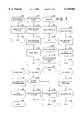
- FIG. 3describes the various software components which comprise the remote data recovery operating program.
- Various Data Recovery Application programs 300operate to effect the data recovery and/or diagnostic processes. Such programs might include storage device functional diagnostic routines, storage media analysis routines, sector editors which work in hexadecimal, ASCII, or other formats relevant to the file system under recovery, file unerase routines, and filesystem integrity checking/repairing routines relevant to the file system under recovery. These Data Recovery Application programs 300 correlate in general terms to routines found in the NORTON UTILITIES® or Ontrack's ODR-NTM or DOSUTILS® software packages.
- the Data Recovery Application DRA programs 300interface with the local RDR application 308, through a set of application program interfaces (API's) 310 which interface direct with the basic input/output subsystem (BIOS) 360 and/or the Operating System 340.
- the local RDR application 308effectively redirects, or "hooks” these API's in order to allow remote control operation of the DRA 300.
- the local RDR application 308offers private API's which allow "RDR aware” applications to interface directly with the communications subsystem 312 by providing a "pass through” to "hooked" BIOS functions 316 and OS functions 314. This permits "RDR aware” applications to bypass the redirection of functions, thus enabling an interface to the operator of the local RDR computer 20, as well as the control of the communications subsystem.
- the remainder of the local RDR application 308contains communications subsystem code 318 and the local RDR application code 320.
- a flow diagram of the local RDR application code 320is shown in FIG. 4.
- the software components of such a systemmay include a Data Recovery Operating System (DROS) 306 as the local RDR computer operating system 340.
- the DROS 306allows remote data recovery to occur when the local RDR computer's native operating system does not function.
- the DROS 306includes routines necessary to support the local RDR application 308 and any desired data recovery application programs 300 used to perform the data recovery process. Examples of such necessary routines include memory management, file system access and management, application program loading and execution, and peripheral device control functions. These routines generally equate to several of the MS-DOS interrupt 21H functions.
- the DROS 306may directly emulate the native operating system's calling conventions and protocol. Additionally, a user command interpretation functionality which resembles the native command line interpreter may be provided.
- the local RDR application 308may also be run using the native operating system as the local RDR computer operating system 340.
- BIOSBasic Input/Output Subsystem
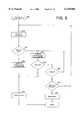
- the flow diagram of FIG. 4describes the operation of the local RDR application 308.
- the Private API's 312, 314 and 316are installed and appropriate Operating System and BIOS "hooks" are installed. This causes any subsequently loaded program to operate under remote control.
- a menuis offered to the operator of the local RDR computer 20 which allows him to specify operation as a New User, a Pre-Registered User, or to Exit the local RDR application 308.
- step 410routines are invoked which assess the hardware configuration of the local RDR computer.
- the useris then requested, at step 412, to fill in forms 2210 and 2220 with information regarding the user's identity, phone numbers, etc., as well as a description of the circumstances and nature of the data recovery situation.
- step 414an attempt is made, in step 414, to dial and establish communication with the Remote Data Recovery Facility as a New User.
- Step 420an immediate attempt is made, in step 420, to dial and establish communication with the Remote Data Recovery Facility as a Pre-registered User.
- step 430If the attempt at connecting to the Remote Data Recovery Facility is determined to be unsuccessful, at step 430, a dialog indicating the failed connection is presented, in step 440, to the operator of the local computer, and control is returned to the menu.
- step 430remote controlled activity, under the complete direction of the remote site, is handled according to the logic described hereinbelow, in step 450.
- step 460the communications hardware is instructed to terminate the communications session.
- the local RDR application 308removes the Private API's 312, 314 and 316 and the previously installed Operating System and BIOS "hooks", at step 406.
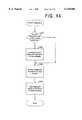
- FIG. 5is a flow diagram of the portion of the local RDR application 308 which executes during remote control operation.
- the local RDR application 308enters a loop, steps 510-550. This loop continually handles all communications events, in step 510, and dispatches any commands which may have been sent from the Remote Data Recovery Facility.
- the remote commandis screened, in step 540, to see if it is a command to hang-up. If a hang-up command has been received, then the routine exits, step 560.
- the commandis passed to the operating system's native command line interpreter, in step 550.
- the local keyboard bufferis filled by a command originating at the remote input device 42, preferably a keyboard. If it has been determined, at step 520, that there is not a complete command in the local keyboard buffer, then an inactivity timeout detects communication failure, at step 530, and causes an appropriate exit at step 560. The corresponding activity directed by the remote site is described in reference to FIG. 12.
- the flow diagram shown in FIG. 6describes the communication event handler within the local RDR application 308.
- the communication event handleris called from a multitude of points within the local hooks, for instance step 450, and several of the Operating System and BIOS hooks.
- the intent of the communication event handleris to service the communications driver, and dispatch any incoming packets, steps 602 through 630.
- the routinedetermines if any new characters have been received, at step 602. If characters have been received, then the characters are placed in the receive buffer, at step 605, and then a check is made to see if there are any complete data packets in the receive buffer, at step 610.
- packet receive control structures 2610If there are any complete packets in the receive buffer, then these completely formed packets are compared to a list of packet receive control structures 2610. The list is maintained as a singly linked list via the pointer link field 2612. The list is searched to find a matching packet receive control structure. If the type field of the packet matches the packet type number field 2614 of the packet receive control structure 2610, then the packet counter field 2616 is incremented and the routine pointed to by the packet handler routine pointer field 2618 is called. A number of packet handling routines are illustrated in FIG.
- step 700file create/open or close ACK packet
- step 700file write-request-list packet
- step 710echo acknowledgment
- step 720screen change acknowledgment
- step 730display data packet
- step 740keystroke packet
- step 750file read packet
- step 760and echo requests, step 770.
- the packet receiveddoes not match, as determined at step 620, then the packet is ignored, at step 630, and the routine returns to searching for complete packets in the receive buffer, at step 610. If no new characters are received at step 602, then a call is made, at step 650, to ensure that any screen updates which may have occurred but were not able to be sent previously are given the opportunity to reach the transmission queue.
- the transmission queueis implemented by a singly linked list of outgoing packet descriptors as shown at 2510 of FIG. 25. Each packet descriptor contains a link 2511 to the next element of the list, followed by a collection of fragment length 2512 and fragment pointer 2514 pairs. Each pair describes a region of memory which would comprise the packet to be formed and transmitted. The collection of pairs is terminated by an entry with a length field of zero as shown at 2516.
- the packets themselvesare formed using this "gather write" principle, and, incorporating whatever other encoding, framing, and error control methods as may be deemed appropriate by the implementor prior to placing the data in the transmit buffer at step 670.
- FIG. 7contains flow diagrams representing the behavior of the local RDR application 308 as it handles various packet types.
- File Create Acknowledgment, File Open Acknowledgment, and File Close Acknowledgment packetsare received at step 700 in response to those packets which were sent requesting the File Create/Open/Close action to occur at the Remote Data Recovery Facility.
- These File Create/Open/Close Acknowledgment packetsare handled at step 702 by merely updating the appropriate file control structure 2520 to reflect the fact that the request has been acknowledged, and to post the status of the File Create/Open/Close operation. This allows the File Create/Open/Close operation which is being acknowledged to proceed.
- File Write Request List packetsare received, at step 710, in response to an initial File Write request. These File Write Request List packets contain a list of those file segments which the Remote Data Recovery Communications Server is prepared to receive. File Write Request list packets are handled by updating, at step 712, the file control structure 2520 to reflect the new request list, and subsequently sending file write data packets, at step 714, per the updated file control structure 2520. Additionally, updating the file control structure 2520 resets the timeout, at step 716. The file read and write hooks are described further with reference to FIG- 10.
- Echo Acknowledgment packetsare received, at step 720, as a response to an Echo Request.
- This echo mechanismis provided for communications diagnostic capabilities.
- Echo Acknowledgment packetsare handled by copying the data content to a dedicated echo buffer, in step 722, such that the program can subsequently further analyze the echo data.
- Screen Change Acknowledgment packetsare received, at step 730, in response to Screen Change Packets.
- Screen Change Acknowledgment packetsare handled by marking the screen change as no longer being in transit, at step 732.
- Display Data Packetsare received, at step 740, as instructions to place text on the local RDR computer monitor 24.
- Display Data Packetsare handled by copying the packet data to the local display 24, at step 742, and then sending a Display Data Acknowledgment packet, at step 744, to notify the Remote Data Recovery Communications Server that the packet was successfully received and rendered on the local display 24.
- Keystroke Packetsare received, at step 750, as keystrokes occur at the RDR workstation 40, and are forwarded through the RDR Communications Server 68. Keystroke Packets are handled by copying the packet keystroke information, at step 752, into the local keyboard buffer. This allows the local RDR application 308 to asynchronously retrieve these keystrokes and interpret them as desired. A Keystroke Acknowledgment packet is then returned, at step 754, after the keystrokes are stored in the local keyboard buffer for subsequent interpretation by the operating system or application programs in the local RDR computer 20.
- File Read Data packetsare received, at step 760, in response to a File Read Request List packet.
- File Read Data packetscontain actual remote file data segments which have been read and forwarded by the RDR Communications Server 68.
- File Read Data packetsare handled by checking, at step 762, to see if the file segment is the expected segment number in sequence. If not, a revised Read Request List packet is sent, at step 766. If the incoming packet contained the expected sequential segment number as detected at step 762, then the file data is copied to the data buffer, at step 764.
- Echo Request Packetsare received, at step 770, as a communications diagnostic request. Such an Echo Request Packet is responded to by copying packet data, at step 772, from the Echo Request Packet, and sending an Echo Reply packet, at step 774.
- FIG. 8is a flow diagram of the communications packet send routine within the local RDR application 308.
- the routinestarts by placing the packet for transmission into the transmit queue, at step 810. If the local RDR application 308 calling this routine 800 has requested that this routine 800 not wait for an acknowledgment (ACK), as determined at step 830, then the routine makes a call, at step 835, to the communications event handler, at step 600, to ensure that the packet has an opportunity to be transmitted, then exits with successful status, at step 890.
- ACKacknowledgment
- a loopis entered which handles communications events until either an ACK occurs, at step 850, leading to a successful exit at step 890, or until a timeout condition is determined at step 860.
- ACKacknowledgment
- the sequence of transmitting the packet and waiting for an acknowledgmentis retried a limited number of times, as determined by step 870.
- a failure after the retry count is exhaustedresults in a failure status exit, at step 880.
- FIG. 9is a flow diagram of the File Create/Open/ Close interceptor, or "hook" within the local RDR application 308. This procedure is installed to preempt an attempt by the application to create, open, or close any arbitrary file. The behavior of this hook is first to determine if the file is a remote or local file, at step 910. This is performed during file open/create operations by examining the file-name supplied by the caller of this routine, be it the local RDR application 308 or a Data Recovery Application 300, utilizing any arbitrary convention for naming remote files which can easily distinguish them from local files, and is performed during file close operations by examining the file-handle supplied by the local RDR application 308.
- step 910If the file is determined to be local by the test, at step 910, execution is transferred to the system's native file create/open/close procedure, at step 912. If the file is determined to be remote, at step 910, an appropriate file create request, file open request, or file close request packet is constructed, at step 920. This packet is then sent, and an acknowledge is waited for, at step 930. The acknowledgment received back reflects the status of the request at the remote end, which affects the content of the file control structure 2520, at step 940. The status is then returned to the operator of the local RDR computer 20 as per the native system's file create/open/close conventions.
- a file handleis be returned to the caller which is easily distinguishable from any file handle which may have legitimately been returned from the system's native file create or open process. This allows future read/write/ close operations to distinguish local files from remote files.
- FIG. 10is a flow diagram of the File Read and Write interceptor, or "hook" within the local RDR application 308. This procedure is installed to preempt any application attempt to read or write any arbitrary file. The behavior of this hook is first to determine if the file is a remote or local file, at step 1010. This is performed by examining the file-handle supplied by the caller of this routine, be it the local RDR application 308 or a Data Recovery Application 300. If the file is determined by the test to be local, at step 1010, execution is transferred to the system's native file read or write procedure, at step 1012. If the file is determined to be remote, then the file control structure 2520 is updated to reflect the nature of the request at step 1020.
- the file control structure 2520is updated to reflect the nature of the request at step 1020.
- an appropriate file read-request or write-request packetis constructed and sent at step 1030.
- a loopis then entered, at step 1040, which continues handling communications events, step 600, and tests whether the read or write request is completely satisfied at step 1050. If the request has been satisfied, then a successful status is returned to its caller, at step 1090, per the native system's file read/write conventions. If the request is not complete, as determined at step 1050, timeout conditions are monitored at step 1060. If no timeout has occurred, then the routine continues to handle communications, at step 1040, and to monitor for completed requests, at step 1050.
- step 1060If a timeout occurs, at step 1060, then the request is resent, at step 1030 for a limited number of retries. If the retry count becomes exhausted, at step 1020, then the request returns failure status, step 1080, per the native system's file read/write conventions.
- the flow diagram for the "hooks" of display screen write and read functions of the local RDR application 308is shown in FIG. 11.
- the mechanism suggestedintends to record and transmit screen changes to the remote site in a timely fashion with minimal impact on program execution.
- the screen write functionis implemented by first copying the desired screen write information into an internal buffer, at step 1110, which entirely describes the state of the display screen.
- the purpose of this bufferis to facilitate the screen read hook, at step 1170, as well as to provide the source for screen update packets as they are formed and transmitted.
- the preferred embodimentutilizes a screen line change descriptor data structure for each line of characters in the local RDR computer display 24. These screen line change descriptors, shown in FIG.
- 25 at 2560describe, for each associated line of characters, the range of columns for which characters have been modified by application programs and those modified characters have not yet been placed in the queue for transmission. This range of modified but unsent columns are referred to as the "dirty" range for that line, and are described by the screen line change descriptors 2560 by entries which mark the first (left-most) dirty column 2562 and the last (right-most) dirty column 2564 for each screen line. Following the copying of the new screen characters to the internal buffer, at step 1110, the screen line change descriptors for each affected display line will be modified to ensure that the "dirty" range includes these newly written columns. A call is then made at 1130 to place any unsent screen changes in the transmission queue 2510 for subsequent transmission to the RDR workstation 40.
- the display screen read function hookis implemented by copying the desired information to the local RDR computer's buffer directly from the internal screen rendition buffer, at step 1180.
- the main application which implements the RDR Communications Server application in an embodiment of the present inventionis described in the flow diagram of FIG. 12.
- an application thread for each network communications hardware unit 69is started which executes steps 1210 through 1280.
- an ASCII promptis transmitted, requesting the operator of the local RDR computer 20 to supply the desired service type, at step 1210.
- the usercan respond to the prompt, set at step 1210 as a "guest".
- Thiscauses the RDR Communications Server application to behave as a classic bulletin board service, with functionality limited only by the creativity of the programmer and the abilities of the local operators terminal application.
- the usefulness of this "guest" category of serviceis that it may be used to promote the organization's services/products, in the manner of a classic BBS. Further, it may be used as a download facility to allow the distribution of the local RDR application 308 and associated programs.
- the local usermay install and utilize the applications to access the "new user" category of service from the RDR Communications Server application.
- the local RDR application 308is knowledgeable of the prompt set at step 1210 and responses which are expected by the RDR Communications Server application, and are described in FIG. 4.
- the RDR Communications Server applicationdetermines whether the local RDR application 308 requests the "new user" category of service, at step 404.
- the files which were produced at the local site describing the hardware configuration, the user information, and the problem description, in steps 410, and 412,are copied to the Remote Data Recovery Facility for further analysis and addition to a registered user database, in step 1230. If it is determined that it is not feasible to proceed with Remote Data Recovery at the present time, at step 1234, a menu is presented and a time to proceed with the Remote Data Recovery process is negotiated, at step 1238.
- the local RDR application 308requests the "pre-registered user" category of service from the RDR Communications Server application at step 1235. Such calls are then authenticated against the registered user database, at step 1240. Non-authentic calls are terminated. As individual communications connections are established, and progress through the various stages illustrated in FIG. 12, the state of progress may be described on the operator's console of the Communications Server 68 in a Communication Channel Status window 2310, for example as is shown in FIG. 23.
- an RDR diagnostic processis performed in step 1250.
- the diagnostic processis described in detail in reference to FIG. 14.
- a custom legal agreement describing the terms of any proposed data recovery serviceis produced and then offered to the operator of the local RDR computer 20, in step 1260.
- the transmission and prosecution of the legal agreementis described in detail in FIG. 15.
- the Remote Data Recovery procedureis performed, in step 1280.
- the Remote Data Recovery procedureis described in detail in reference to FIG. 16.
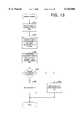
- the flow diagram of FIG. 13describes the portion of the RDR Communications Server application which is invoked if, for whatever reason, it was determined that the data recovery process should take place after the initial registration phone call, at step 1234.
- a file which maintains the schedule and resides on the Network Shared Data Storage 64 of the File Server 60is read at step 1310. This file is then processed at step 1320 with the needs of this particular data recovery situation at hand, to determine a list of appropriate schedule times for processing the RDR process. Such factors as estimated time to perform the recovery, specific technician availability and other prioritization factors may be used to produce this customized list of appropriate times for providing the Remote Data Recovery Service.
- An applicationis activated at the local computer, at step 1330, which then enables viewing the customized schedule list, and, optionally selecting a mutually agreeable time for proceeding with the Remote Data Recovery. If such a time is chosen in step 1340, it is added to the schedule file, at step 1350. If no such time was chosen, at step 1340, a description of further options is presented to the operator of the local RDR computer 20, at step 1360.
- the options presented in step 1360may include sending the equipment in to the Remote Data Recovery Facility for traditional off-site recovery, or, requesting on-site category data recovery services.
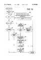
- FIG. 14is a flow diagram of that portion of the Remote Data Recovery Communications Server which facilitates performance of the Data Recovery Diagnostic.
- a checkis first made, in step 1410, to see if a valid copy of the current version of the diagnostic application exists on the distribution media at the local site. If a valid copy of this diagnostic application does not exist or there is no appropriate version of the diagnostic application, an appropriate version of the diagnostic application is downloaded to the local site, at step 1420. Subsequently, or, if the appropriate diagnostic application was determined to exist in step 1410, the diagnostic application is activated at the local computer, in step 1430. The diagnostic application performs diagnosis of the data recovery situation and places results in a file at the Communications Server 68, in step 1440, for further analysis by the remote technician and/or other applications at the Remote Data Recovery Facility.
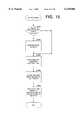
- FIG. 15is a flow diagram of the portion of the Remote Data Recovery Communications Hardware application which facilitates the presentation, and optional acceptance by the operator of the local RDR computer 20, of a legal agreement.
- a checkis made, in step 1510, to see if a valid copy of the current version of the legal agreement exists on the distribution media at the user site. If the legal agreement does not exist or it is not an appropriate version, an appropriate version of the legal agreement is downloaded to the local site, at step 1520. Following downloading 1520, or, a determination that the appropriate legal agreement is in place at step 1510, the current date and time are noted, at step 1530.
- An Agreement Reader applicationis then activated at the local RDR computer 20, at step 1540.
- the Agreement Reader applicationallows the operator of the local RDR computer 20 to inspect the legal agreement, and optionally accept the terms included therein.
- the accept/decline response made by the operator, and the current date and timeare again noted, at step 1550. Having accurate knowledge of the date and time of agreement presentation and agreement acceptance may be relevant factors in resolving any possible disputes which may arise regarding contested agreements.
- FIG. 16is a flow diagram of the portion of the Remote Data Recovery Communications Server application which performs the Remote Data Recovery. This process is accomplished by enabling the technician, operating an RDR workstation 40, to remotely control the local RDR computer 20. A logical connection is formed, at step 1610, via TCP/IP with an arbitrary RDR workstation 40 which is available to perform a Remote Data Recovery procedure. Additionally, a unique subdirectory for this session of Remote Data Recovery is created, at step 1620, on the Network Shared Data Storage 64 of the File Server 60. This unique subdirectory is the repository for any session-unique files created by the operator of the local RDR computer 20, as well as any log files which the RDR Communications Server application or the RDR workstation 40 may wish to create.
- a loop, steps 1640-1660,is then entered which processes any communications packets from the local RDR computer 20, at step 1640, as well as any TCP/IP messages from the RDR workstation 40, at step 1650. If no "hang-up" message is determined to have been received from the RDR workstation 40, in step 1660, then the loop persists. Eventually, the RDR workstation operator causes a "hang-up” message to be sent which breaks the loop, at step 1660, and causes a "HANG-UP" command to be forwarded to the local RDR computer 20, at step 1670.
- FIG. 17is a flow diagram of the portion of the RDR Communications Server application which responds to packets arriving from the local RDR computer 20 over the network communications hardware unit 69 which request a remote file to be opened, created, or closed.
- the packetcontains a file index which ranges from 0 to the maximum number of concurrently open files, and a sequence number which is utilized to distinguish this request as a unique use of the file index. It is therefore possible to utilize the combination of file index and sequence number to determine if this is a unique request, or if this is a retry of a request for which the acknowledgment was lost due to an error in the communications channel 35.
- the fileis opened/created/closed per the remainder of the packet, at step 1720. If the request is indeed a repeat request, as determined at step 1710, then the file actual open/create/close is bypassed. If the open/create/close request is not successful, as determined at step 1730, a Failure Acknowledgment is transmitted, at step 1760. Alternatively, if the determination, at step 1730, is that the open/create/close request was successful, then the File Connection Data Structures are initialized within the Remote Data Recovery Communications Server, at step 1740, per the open/create/close request packet and then a Successful Acknowledgment is sent, at step 1750.
- FIG. 18is a flow diagram of the portion of the RDR Communications Server application which responds to those packets arriving from the local RDR computer 20 over the network communications hardware unit 69 which request File Write activity.
- the first packet receivedis a Write File Initialization Packet, which is checked against the sequence number of the last activity on the file to see if it is a retry of a previously received request, at step 1810. If it is determined that this is not a retry, at step 1810, initialization, including allocation of memory for the activity as well as preparation of the initial file control structure 2620 is performed, at step 1850. If it is determined not to be a retry, at step 1810, then initialization has already been performed but the acknowledgment was lost due to communications errors, and so the initialization is skipped.
- a testis made, at step 1860, to determine if all write data has been received to satisfy the entire Write File Initialization Packet. If all data has been received, any data which remains in memory buffers is actually written to the file, at step 1865. The memory which was allocated at step 1850 is now de-allocated at step 1870, and a null request list is sent at step 1880 to indicate that the file write is complete. If, during the test at step 1860, it was determined that there was more file data to be received, an appropriate write request list packet is formulated and sent at step 1890. This request-list requests those file data segments for which data has not yet been received and for which there is available buffer space which currently does not contain any unwritten data.
- step 1825If the segment is determined to be in sequence, at step 1825, as is the case in the absence of communications errors, a test is made, at step 1830, to see if file write activity is currently taking place. If there is no file write activity, then a file write is initiated, at step 1835, of any data buffers which contain unwritten file data. The request-list is then adjusted, at step 1840, to take into account those file segments received thus far, as well as any file data buffers which are now free to receive more data. Processing then continues at Point A.
- FIG. 19describes various packet handlers which exist in the embodiment of the RDR Communications Server application.
- Echo Request packetsare handled, in the routine commencing at step 1900, by sending an Echo Acknowledgment packet, at step 1902, which-contains a copy of any optional Echo Data which was in the original Echo Request packet.
- File Read Request List packetscontain a list of segments of the file for which the local user is ready to receive data. These File Read Request List packets are handled by the routine starting at step 1910, by performing the actual read, at step 1920, and then sending the data, at step 1930, in the form of File Read Data packets.
- Screen Change Packetshandled by the routine starting at step 1939, are tested, at step 1940, to see if they are retries of a packet already processed.
- This testis performed by virtue of the sequence number contained within the packet. If the packet is determined not to be a retry, at step 1940, it is then processed, at step 1950, by forwarding to the Remote Data Recovery Workstation via a TCP/IP connection. Following this action, or, if the packet was determined to be a retry, a Screen Change Acknowledgment packet is sent, at step 1960, to the local RDR computer 20.
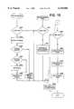
- FIG. 20is a flow diagram representing a thread of execution, steps 2002-2008, which operates continuously within the RDR Communications Server Application for monitoring Remote Data Recovery Workstation connections, and a thread of execution which continuously handles messages from RDR workstations 40 while they are actively involved in remote data recovery operations.
- connection monitor threadmonitors a TCP/IP port which is known to all RDR workstations 40 on the system.
- the RDR Communications Server applicationwaits, at step 2002, for any RDR workstation 40 to establish a TCP/IP connection. Therefore, any RDR workstation 40 which activates its RDR workstation application, discussed later in reference to FIG. 21, establishes a logical connection via this port.
- a TCP/IP connectionis established on this port, another thread of execution is spawned, at step 2006, which handles messages from the RDR workstation 40.
- the RDR workstation 40 thus connectedis noted, at step 2008, as being capable of processing remote data recovery service.
- Those RDR workstation connections so noted at step 2008may be described on the operator's console of the Communications Server 68 in a Workstation Status window 2320 as shown in FIG. 23.
- the thread, steps 2010-2075, which is spawned, at step 2006, as a result of the TCP/IP connection,is responsible for handling all TCP/IP messages sent by the RDR workstation 40.
- a separate thread of this sortexists within the RDR Communications Server application for all RDR workstations 40 which are currently established as potential providers of remote data recovery service. These threads begin receiving messages as the operator of the RDR workstation 40 performs activity in the performance of remote data recovery.
- TCP/IP messagesare generally handled by forwarding these messages to the local RDR computer 20 via various packets over the communications hardware.
- TCP/IP messages which represent keystrokesare detected, at step 2020, and forwarded, at step 2025, to the local RDR computer 20 as Keystroke packets.
- TCP/IP messages which represent Display Messagesare detected, at step 2030, and a forwarded, at step 2035, to the local RDR computer 20 as Display Data packets.
- a "HANG-UP" TCP/IP messageis detected, at step 2040, and forwarded, at step 2045, to cause the local RDR computer 20 to hang-up the telephone connection.
- the remaining TCP/IP message typeis the "LOGOUT" message, which occurs as the result of the RDR Workstation operator exiting the RDR Workstation application.
- the "LOGOUT" messageis detected, at step 2050, it causes the RDR Communications Server application to note, at step 2075, that this RDR workstation 40 is no longer ready to process remote data recovery services.
- the TCP/IP connectionis then closed and this thread of execution terminates, at step 2080.
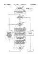
- FIG. 21is a flow diagram representing the overall operation of the application which controls the RDR workstation 40.
- a logical connectionis established, at step 2110, with a RDR Communications Server application via a pre-determined, fixed TCP/IP port on the RDR Communications Server 68.
- a loop, steps 2115-2120,is then entered which waits until either the Workstation Operator requests that the application be exited, at step 2115, or, a TCP/IP message arrives, at step 2120, from the RDR Communications Server application requesting the start of a Remote Data Recovery session.
- the Communications Server 68issues a TCP/IP request to start a Remote Data Recovery session at step 1610.
- This request 1610is detected by the RDR workstation 40, at step 2120, and a collection of windows 2410, 2420 and controls 2430, 2440 are drawn on the RDR workstation console 44, as illustrated in FIG. 24.
- the macro control buttons 2430are provided to allow a "macro" capability, such that activation of any individual button issues the equivalent of multiple, pre-configured keystrokes.
- the status control buttons 2440are provided to allow the capability of specifying status messages for display on the RDR local computer console 24.
- window 2410shows all screen activity performed by those Data Recovery Application Programs 300 operating at the local RDR computer 20.
- any keystrokes from the RDR workstation keyboard 42are sent via TCP/IP to the Communications Server 68 for forwarding 2020, 2025 to the local RDR computer 20 as keystroke packets.
- These keystroke packetsare received by the local RDR computer 20 as shown at steps 750 and 755 in FIG. 7, thus allowing the operator of the RDR workstation 40 to control the Data Recovery Application Programs 300 operating at the local RDR computer 20.
- any Display Data messages which were specified via the activation of control buttons 2440are sent via TCP/IP to the Communications Server 68 for forwarding 2030, 2035 to the local RDR computer 20 as Display Data packets.
- the local RDR computer 20handles these packets by copying them to the local-screen at step 742. Additionally at step 2140, these Display Data messages are rendered on the window 2420, such that the window 2420 maintains an accurate representation of the appearance of the local RDR computer console 24.
- a "HANG-UP" messageis sent to the communications server 68 and the windows 2410 and 2420 and controls 2430 and 2440 are cleared, at step 2155.
- FIG. 22contains depictions of computer screens representing forms displayed on the local display 24 which the user of the local RDR computer 20 may fill in to provide information regarding the identity of the user, the nature of the present data loss situation and the corresponding service desired.
- User identification and other relevant informationis ascertained by the form 2210.
- Information relevant to the proper diagnosis of the data loss and relevant to describing the desired serviceis ascertained by the user filling out form 2220.
- FIG. 23contains depictions of computer screens displayed by the communications server application which provide the administrators of the Remote Data Recovery Facility to manage the communications server 68.
- a Communication Channel Status Window 2310is provided to facilitate monitoring of the status of each configured LAN communication channel 66.
- Each LAN communication channel 66may be in a waiting mode, a guest mode, a new user mode, an active data recovery mode, or may be off-line. Additional controls may be provided to facilitate maintenance and configuration of individual LAN communication channels 66 or the communications server 68 as a whole.
- a Workstation Status Window 2320is provided to allow monitoring of those Remote Data Recovery Workstations 40 which have established TCP/IP connections to the Communications Server 68, and an indication as to the current activity being performed at those Remote Data Recovery Workstations 40.
- FIG. 24contains depictions of computer screens which can be displayed on the RDR workstation display 44. These screens allow the user of the RDR workstation 40 to control and to monitor output from programs of the local RDR computer 20, and to control and to monitor the appearance of the actual screen of the local RDR computer display 24.
- the Local Program Output window 2410is a display of the output of all RDR applications 300. This output enables the operator of the RDR workstation 40 to monitor the applications running on the local RDR computer 20.
- the macro control buttons 2430provide methods for the operator of the RDR workstation 40 to send frequently-used keystroke sequences to the local RDR computer 20.
- the Actual Local Display window 2420then is a display which follows the content of the local RDR computer display 24. This allows the operator of the RDR workstation 40 to remain aware of the status messages which have been displayed.
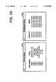
- FIG. 25contains descriptive drawings of data structures utilized in an embodiment of the local RDR application 300.
- Diagram 2510describes an Outgoing Packet Descriptor (OPD) data structure.
- OPDOutgoing Packet Descriptor
- This OPD 2510, and any OPD's which are linked via the link list pointer 2511,comprise the transmission queue within the Communications subsystem code 318 of the local RDR application 308.
- the remainder of the data structureconsists of pairs of Fragment Length fields 2512 and Fragment Pointer fields 2514. Any number of such pairs of Fragment Length fields 2512 and Fragment Pointer fields 2514 may exist, until a pair with a zero Fragment Length field is encountered 2516, which terminates the list of pairs.
- Each pairdescribes a region of memory which comprises a portion of the outgoing packet. This is a classical "gather-write" approach which allows the collection of various portions of the outgoing packet to be collected from widely separated regions of memory.
- Diagram 2520illustrates a local File Control Structure (local FCS).
- local FCS 2520exists for every potentially concurrent instance of an open remote file within the Local Remote Data Recovery application 308. Further insight into the use of this data structure can be gained by referencing the flow diagrams of FIGS. 7, 9, and 10 as well as the detailed descriptions associated with those flow diagrams.
- the local FCS 2520contains a Status Field 2522 which represents the current state of the file, as currently open, currently closed, or in some intermediate state as communications occur.
- the Sequence Number Field 2524is altered prior to the initial communications for every remote file read, write, open, create, or close attempt. As such, the Remote Data Recovery Communications Server 68 can determine whether such requests are new requests or retries of requests for which the response was lost due to a communications error.
- Retriesare counted on a per-request basis with the Retry Count Field 2526, such that a limited number of retries can be attempted before an operation is aborted.
- the Current File Pointer field 2528is utilized to maintain a record of the offset in the file as used for stream operations.
- a Time Out Field 2530exists to allow determination of whether sufficient real time has elapsed between the request and any response to that request. Whenever sufficient time has elapsed, it is then assumed that either the request or the response to that request has been lost.
- a Read Request List packetis sent to request those file segments which are desired but not yet received.
- Filesare transferred on the basis of quantum units called segments, the segment being a fixed size sequential fragment of the file. Any file data transfer packet contains at most one segment.
- the fixed size of the segmentis predetermined by the programmer, and is based on comnputational convenience, file system performance, and in consideration of the resulting packet size.
- the Request Listis created with an initial segment value equal to the Next Segment To Be Received 2532, and requests as many sequential segments as possible without overrunning the Total Segments Left to Receive Field 2534. Any segments which are received out of sequence are discarded and immediately cause a revised Read Request List to be created and placed in the transmission queue at step 766 of FIG. 7. Also, any timeout condition causes a revised Read Request List to be created and placed in the transmission queue at step 1030 of FIG. 10.
- a Write Initialization packetis sent, the Write Initialization packet including a starting segment number and a total byte count.
- This packetallows the Communications Server 68 to request file segments as the Communications Server's buffering and I/O subsystems becomes ready to receive file segments.
- the Communications Server 68makes such requests for file segments by sending File Write Request List packets, which are processed at step 712 of FIG. 7.
- the data structure fields First Segment Requested 2536 and Segment Count Requested 2538are taken directly from the File Write Request List packet.
- File Write Data packet(s)are then placed in the transmission queue.
- the Next Segment To Send field 2540is utilized to determine which file segment to start placing in the queue.
- Diagram 2560describes Screen Line Change Descriptor (SLCD) data structures used to keep track of which portions of the virtual screen written to by RDR applications 300 have not yet been successfully transmitted to the RDR Communications Server 68.
- SLCDScreen Line Change Descriptor
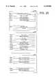
- FIG. 26contains descriptive drawings of further data structures utilized in an embodiment of the local RDR application 308 as well as descriptive drawings of data structures utilized in an embodiment of the RDR Communications Server application.
- the data structure described in FIG. 26 at 2610is the Packet Receive Control (PRC) structure.
- the PRCis utilized by the RDR local application 308 to decode incoming packets, maintain statistics, and transfer control to the routines of FIG. 7, which are responsible for handling each specific type of incoming packet.
- the Pointer Link to Next Packet Receive Structure field 2612is utilized to maintain a collection of such structures in a classic singly linked list.
- the Packet Type Number field 2614is matched against the type field of incoming packets, and determines whether this packet should be handled in accordance with this PRC or a subsequent PRC.
- the Packet Counter field 2616is incremented to maintain statistics, and the software routine pointed to by the Pointer to Packet Handler Routine field 2618 is called to handle the processing of the incoming packet.
- the data structure 2620is the File Control Structure (FCS) as utilized within the RDR Communications Server 68.
- FCSFile Control Structure
- One Server FCS 2620exists for every potentially concurrent instance of an open remote file within the RDR Communications Server application. Further insight into the use of this data structure can be gained by referencing the flow diagrams of FIGS. 18 and 19 as well as the detailed descriptions associated with those flow diagrams.
- the Server FCS 2620contains a Status Field 2622 which represents the current state of the file, as currently open, currently closed, or in some intermediate state as communications occur.
- the Last Sequence Number Field 2624is checked on every remote file read, write, open, create, or close attempt. As such, the RDR Communications Server application can determine whether such requests are new requests or retries of requests for which the response was lost due to communications error.
- Retriesare counted on a per-request basis with the Retry Count Field 2626, such that a limited number of retries can be attempted before an operation is aborted.
- a Time Out Field 2630exists to allow determination of whether sufficient real time has elapsed between the request and any response to that request. Whenever sufficient time has elapsed, it is then assumed that either the request or the response to that request has been lost.
- the Actual File Handle field 2636is used to hold the actual file handle utilized by the system for referencing this file in future read, write, or close requests.
- Read Request List packetsare responded to by merely performing the actual file read as specified in the request list and subsequently sending the requested file data as File Read Data packet(s). Should a Read Request List packet arrive while File Read Data packets are being sent, it should be assumed that a packet was lost due to communications error, and the prior sequence of File Read Data should be halted and the new Read Request List should be honored. Relevant fields of the FCS data structure during read operations are the Current File Pointer 2628, First Segment Requested 2632, Segment Count Requested 2634. These fields are filled from the contents of the Read Request List packet, and are adjusted as the associated File Read Data packets are transmitted.
- Write File Initialization packetsare received to define the intended write operation.
- the Write File Initialization packetprovides information for the Current File Pointer 2628, First Segment Requested 2632, and Segment Count Requested 2634 fields of the Server FCS 2620. Additionally, memory is allocated per the request and in consideration of system resource utilization.
- the Number of Free Segment Buffers field 2636, the Total Number of Segments field 2640, and the Pointers to Segment Buffers 2642are set to reflect the number of segment buffers allocated and their memory location. As Write File Data packets arrive, they are placed into available buffers and scheduled for writing to the file.
- File Write Request List packetsare formulated by utilizing the First Segment Requested field 2632 as a starting segment number, and the number of requested segments is limited by either the number of Free Segment Buffers 2638 or the Segment Count Requested 2634 fields.
- First Segment Requested 2632 and Segment Count Requested 2634 fieldsare incremented and decremented, respectively, as File Data packets arrive, such that they maintain an accurate description of the file data remaining to be received.
- the principle of the present inventionis to allow diagnosis of data storage devices and/or data recovery by a remote data recovery computer. In some cases, only the diagnosis is carried out remotely, as the user may elect not to proceed with the actual recovery. In some cases, the recovery is performed at the local computer-and the recovered data re-stored on the local user's storage device 26. In many cases, the data may be downloaded to the RDR network shared drives 65, restored, and saved on a new storage media which is then sent to the user and/or picked up by the user. In some cases, damaged data may be downloaded to the RDR network shared drives 65, restored, and then uploaded back to the local RDR computer 20. It will be appreciated that these are but some of the many scenarios that might occur under the principles of the present invention.
- RDRRemote Data Retrieval
- a means for logging eventssuch as the following:
- Connection startdate/time, client job-id and phone number, communications channel type and speed;
- a mechanismis provided to defer all changes to the local storage device until such time as the operator of the RDR workstation makes the decision to continue or, alternatively, abandon said changes. If the decision is made to commit the changes, then all data which is marked for being changed is first transferred to the RDR facility for archival. Only then is the new data actually written to the local storage device 26.
- the preferred method to implement such a mechanismis with a file which logs all write activity which would be performed on the local storage device 26.
- the fileresides on the network attached storage device 65 at the remote data recovery site.
- Each entry within the filecontains an identifier which identifies the unique sector and local storage device which is represented, as well as the latest data which was written to that sector. It is effectively a "write-cache".
- FIG. 27is a flow diagram of the IO logic layer within the local RDR application 308 which implements the capability of "undoing" any modifications made to the local data storage device 26. All attempts to write to the local storage device 26 enter this IO logic layer at 2710. If the requested sector(s) have not been previously written there will be no existing entry in the log-file. If this condition is detected at 2720, a log-file entry will be added at 2730, and at 2735 the data to be written will be written into the log-file entry. If at 2720, it is detected that the requested sector(s) have been previously written, the existing log-file entry will be updated at 2740 with the new data to be written.
- FIG. 28is a flow diagram of the application which manipulates the log-files to facilitate the abandonment of changes, the committing of the new data, and the potential restoration of original data.
- Sectors which are decided to have been inappropriately modifiedcan be "undone" at 2810 by removing the corresponding log-file entries at 2815.
- the original datais transferred at 2830 to a file on the network attached storage device 65 at the remote data recovery site. This original data log-file is then archived at 2840. Finally, since the original data has now been safely archived, the log-file data is used to modify the local storage device 26 at 2850.
Landscapes
- Engineering & Computer Science (AREA)
- Theoretical Computer Science (AREA)
- General Engineering & Computer Science (AREA)
- Quality & Reliability (AREA)
- Physics & Mathematics (AREA)
- General Physics & Mathematics (AREA)
- Computer Hardware Design (AREA)
- Information Transfer Between Computers (AREA)
Abstract
Description
Claims (71)
Priority Applications (11)
| Application Number | Priority Date | Filing Date | Title |
|---|---|---|---|
| US08/877,125US6145088A (en) | 1996-06-18 | 1997-06-17 | Apparatus and method for remote data recovery |
| AT97930000TATE262195T1 (en) | 1996-06-18 | 1997-06-18 | DEVICE AND METHOD FOR REMOTE DATA RECOVERY |
| EP97930000AEP0980550B1 (en) | 1996-06-18 | 1997-06-18 | Apparatus and method for remote data recovery |
| JP50316698AJP4616423B2 (en) | 1996-06-18 | 1997-06-18 | Apparatus and method for remote data recovery |
| DE69728178TDE69728178T2 (en) | 1996-06-18 | 1997-06-18 | DEVICE AND METHOD FOR REMOVING DATA RECOVERY |
| AU33933/97AAU716035B2 (en) | 1996-06-18 | 1997-06-18 | Apparatus and method for remote data recovery |
| CNB971974217ACN1163827C (en) | 1997-06-17 | 1997-06-18 | Remote data recovery apparatus and method |
| PCT/US1997/010327WO1997049056A2 (en) | 1996-06-18 | 1997-06-18 | Apparatus and method for remote data recovery |
| ES97930000TES2218688T3 (en) | 1996-06-18 | 1997-06-18 | APPARATUS AND METHOD FOR RECOVERING DATA DISTANCE. |
| CA002258798ACA2258798C (en) | 1996-06-18 | 1997-06-18 | Apparatus and method for remote data recovery |
| US09/620,459US6826707B1 (en) | 1996-06-18 | 2000-07-20 | Apparatus and method for remote data recovery |
Applications Claiming Priority (2)
| Application Number | Priority Date | Filing Date | Title |
|---|---|---|---|
| US66795696A | 1996-06-18 | 1996-06-18 | |
| US08/877,125US6145088A (en) | 1996-06-18 | 1997-06-17 | Apparatus and method for remote data recovery |
Related Parent Applications (1)
| Application Number | Title | Priority Date | Filing Date |
|---|---|---|---|
| US66795696AContinuation-In-Part | 1996-06-18 | 1996-06-18 |
Related Child Applications (1)
| Application Number | Title | Priority Date | Filing Date |
|---|---|---|---|
| US09/620,459ContinuationUS6826707B1 (en) | 1996-06-18 | 2000-07-20 | Apparatus and method for remote data recovery |
Publications (1)
| Publication Number | Publication Date |
|---|---|
| US6145088Atrue US6145088A (en) | 2000-11-07 |
Family
ID=24680372
Family Applications (1)
| Application Number | Title | Priority Date | Filing Date |
|---|---|---|---|
| US08/877,125Expired - LifetimeUS6145088A (en) | 1996-06-18 | 1997-06-17 | Apparatus and method for remote data recovery |
Country Status (1)
| Country | Link |
|---|---|
| US (1) | US6145088A (en) |
Cited By (78)
| Publication number | Priority date | Publication date | Assignee | Title |
|---|---|---|---|---|
| US20020042892A1 (en)* | 2000-10-06 | 2002-04-11 | Stephen Gold | Performing operating system recovery from external back-up media in a headless computer entity |
| US20020053044A1 (en)* | 2000-10-06 | 2002-05-02 | Stephen Gold | Self-repairing operating system for computer entities |
| US6389552B1 (en)* | 1998-12-31 | 2002-05-14 | At&T Corp | Methods and systems for remote electronic vaulting |
| WO2003025760A1 (en)* | 2001-09-20 | 2003-03-27 | Cebridge Pty. Ltd. | Data protection and retrival |
| GB2387455A (en)* | 2002-04-12 | 2003-10-15 | Sernat Systems Ltd | Improvements in or Relating to Data Recovery Systems |
| US20040059782A1 (en)* | 2002-09-20 | 2004-03-25 | American Megatrends, Inc. | Systems and methods for establishing interaction between a local computer and a remote computer |
| US6741683B1 (en) | 2001-12-21 | 2004-05-25 | Charles Michael Shelton | On-hold message updating system and method |
| US6757837B1 (en)* | 1999-10-19 | 2004-06-29 | Tivo, Inc. | Method and apparatus for software failure diagnosis and repair |
| US20040153724A1 (en)* | 2003-01-30 | 2004-08-05 | Microsoft Corporation | Operating system update and boot failure recovery |
| US20040190773A1 (en)* | 2003-03-31 | 2004-09-30 | American Megatrends, Inc. | Method, apparatus, and computer-readable medium for identifying character coordinates |
| US20040243883A1 (en)* | 2003-05-27 | 2004-12-02 | American Megatrends, Inc. | Method and system for remote software debugging |
| US20040255276A1 (en)* | 2003-06-16 | 2004-12-16 | Gene Rovang | Method and system for remote software testing |
| US20050235007A1 (en)* | 2004-04-16 | 2005-10-20 | International Business Machines Corporation | Diagnostic repair system and method for computing systems |
| US20060159025A1 (en)* | 2002-06-24 | 2006-07-20 | Miguel Abdo | Determination of network performance characteristics |
| US20060167950A1 (en)* | 2005-01-21 | 2006-07-27 | Vertes Marc P | Method for the management, logging or replay of the execution of an application process |
| US7089449B1 (en)* | 2000-11-06 | 2006-08-08 | Micron Technology, Inc. | Recovering a system that has experienced a fault |
| US20060282834A1 (en)* | 1996-06-07 | 2006-12-14 | William Cheng | Software uninstallation system, method and computer program product |
| US20070005741A1 (en)* | 2005-06-30 | 2007-01-04 | Microsoft Corporation | Facilitating radio communications in a mobile device |
| US20070043874A1 (en)* | 2005-08-17 | 2007-02-22 | Virendra Nath | File transfer method and system |
| US20070053335A1 (en)* | 2005-05-19 | 2007-03-08 | Richard Onyon | Mobile device address book builder |
| US7200775B1 (en) | 2002-10-04 | 2007-04-03 | American Megatrends, Inc. | Method and data structures for use in providing on-demand computer diagnostics |
| US7231549B1 (en)* | 2002-10-04 | 2007-06-12 | American Megatrends, Inc. | Method and apparatus for providing on-demand computer diagnostics |
| US20070263634A1 (en)* | 2000-12-08 | 2007-11-15 | Mike Reeves | MPLS implementation of an ATM platform |
| US7334006B1 (en)* | 2000-09-27 | 2008-02-19 | Microsoft Corporation | Off-line support for cumulative backups |
| US7334166B1 (en) | 2002-10-04 | 2008-02-19 | American Megatrends, Inc. | Method, system, and apparatus for providing and utilizing server-side entry points for use in diagnostics on-demand services |
| US20080072236A1 (en)* | 2005-03-10 | 2008-03-20 | Pope Steven L | Data processing system |
| US7398286B1 (en)* | 1998-03-31 | 2008-07-08 | Emc Corporation | Method and system for assisting in backups and restore operation over different channels |
| US20080208617A1 (en)* | 2004-02-27 | 2008-08-28 | Onyon Richard M | Wireless telephone data backup system |
| US20080256236A1 (en)* | 2002-08-23 | 2008-10-16 | Finite State Machine Labs, Inc. | System, method and computer program product for monitoring and controlling network connections from a supervisory operating system |
| US7519749B1 (en) | 2004-08-25 | 2009-04-14 | American Megatrends, Inc. | Redirecting input and output for multiple computers |
| US7543277B1 (en) | 2003-06-27 | 2009-06-02 | American Megatrends, Inc. | Method and system for remote software debugging |
| US20090150554A1 (en)* | 2007-12-07 | 2009-06-11 | Leigh Rothschild | Digital media communication protocol |
| US7783799B1 (en) | 2006-08-31 | 2010-08-24 | American Megatrends, Inc. | Remotely controllable switch and testing methods using same |
| US7818435B1 (en) | 2000-12-14 | 2010-10-19 | Fusionone, Inc. | Reverse proxy mechanism for retrieving electronic content associated with a local network |
| US7827258B1 (en) | 2004-03-01 | 2010-11-02 | American Megatrends, Inc. | Method, system, and apparatus for communicating with a computer management device |
| US7895334B1 (en) | 2000-07-19 | 2011-02-22 | Fusionone, Inc. | Remote access communication architecture apparatus and method |
| US8010843B2 (en) | 2005-12-14 | 2011-08-30 | American Megatrends, Inc. | System and method for debugging a target computer using SMBus |
| US8073954B1 (en) | 2000-07-19 | 2011-12-06 | Synchronoss Technologies, Inc. | Method and apparatus for a secure remote access system |
| US8156074B1 (en) | 2000-01-26 | 2012-04-10 | Synchronoss Technologies, Inc. | Data transfer and synchronization system |
| US8181111B1 (en) | 2007-12-31 | 2012-05-15 | Synchronoss Technologies, Inc. | System and method for providing social context to digital activity |
| US8255006B1 (en) | 2009-11-10 | 2012-08-28 | Fusionone, Inc. | Event dependent notification system and method |
| US8291034B1 (en)* | 2006-12-15 | 2012-10-16 | The Research Foundation Of State University Of New York | Centralized adaptive network memory engine |
| US8442943B2 (en) | 2000-01-26 | 2013-05-14 | Synchronoss Technologies, Inc. | Data transfer and synchronization between mobile systems using change log |
| US20130212583A1 (en)* | 2011-07-20 | 2013-08-15 | Bank Of America Corporation | Resiliency tracking for project task management |
| US8611873B2 (en) | 2004-05-12 | 2013-12-17 | Synchronoss Technologies, Inc. | Advanced contact identification system |
| US8615566B1 (en) | 2001-03-23 | 2013-12-24 | Synchronoss Technologies, Inc. | Apparatus and method for operational support of remote network systems |
| US8620286B2 (en) | 2004-02-27 | 2013-12-31 | Synchronoss Technologies, Inc. | Method and system for promoting and transferring licensed content and applications |
| US8645471B2 (en) | 2003-07-21 | 2014-02-04 | Synchronoss Technologies, Inc. | Device message management system |
| US8667017B1 (en)* | 2005-01-21 | 2014-03-04 | Invensys Systems, Inc. | Method for portal-based collaborative process management and information access |
| US8737431B2 (en) | 2004-04-21 | 2014-05-27 | Solarflare Communications, Inc. | Checking data integrity |
| US8782642B2 (en)* | 2005-03-15 | 2014-07-15 | Solarflare Communications, Inc. | Data processing system with data transmit capability |
| US8943428B2 (en) | 2010-11-01 | 2015-01-27 | Synchronoss Technologies, Inc. | System for and method of field mapping |
| DE10297001B4 (en)* | 2001-06-28 | 2015-07-23 | Emc Corp. | Information reproduction system with improved error detection and reconstruction |
| US20150269203A1 (en)* | 2014-03-20 | 2015-09-24 | International Business Machines Corporation | Accelerated access to objects in an object store implemented utilizing a file storage system |
| US9300723B2 (en) | 2007-12-07 | 2016-03-29 | Display Technologies, Llc | Enabling social interactive wireless communications |
| US9542076B1 (en) | 2004-05-12 | 2017-01-10 | Synchronoss Technologies, Inc. | System for and method of updating a personal profile |
| US9729436B2 (en) | 2005-03-30 | 2017-08-08 | Solarflare Communications, Inc. | Data processing system with routing tables |
| US10015104B2 (en) | 2005-12-28 | 2018-07-03 | Solarflare Communications, Inc. | Processing received data |
| CN110865890A (en)* | 2018-08-28 | 2020-03-06 | 龙芯中科技术有限公司 | Event processing method and device based on remote connection and storage medium |
| US10614519B2 (en) | 2007-12-14 | 2020-04-07 | Consumerinfo.Com, Inc. | Card registry systems and methods |
| US10621657B2 (en) | 2008-11-05 | 2020-04-14 | Consumerinfo.Com, Inc. | Systems and methods of credit information reporting |
| US10628448B1 (en) | 2013-11-20 | 2020-04-21 | Consumerinfo.Com, Inc. | Systems and user interfaces for dynamic access of multiple remote databases and synchronization of data based on user rules |
| US10642999B2 (en) | 2011-09-16 | 2020-05-05 | Consumerinfo.Com, Inc. | Systems and methods of identity protection and management |
| US10671749B2 (en) | 2018-09-05 | 2020-06-02 | Consumerinfo.Com, Inc. | Authenticated access and aggregation database platform |
| US10685398B1 (en) | 2013-04-23 | 2020-06-16 | Consumerinfo.Com, Inc. | Presenting credit score information |
| US10798197B2 (en) | 2011-07-08 | 2020-10-06 | Consumerinfo.Com, Inc. | Lifescore |
| US10929925B1 (en) | 2013-03-14 | 2021-02-23 | Consumerlnfo.com, Inc. | System and methods for credit dispute processing, resolution, and reporting |
| US10956174B1 (en)* | 2015-10-05 | 2021-03-23 | Veritas Technologies Llc | Lazy bare metal restore |
| US10963959B2 (en) | 2012-11-30 | 2021-03-30 | Consumerinfo. Com, Inc. | Presentation of credit score factors |
| US11012491B1 (en) | 2012-11-12 | 2021-05-18 | ConsumerInfor.com, Inc. | Aggregating user web browsing data |
| US11113759B1 (en) | 2013-03-14 | 2021-09-07 | Consumerinfo.Com, Inc. | Account vulnerability alerts |
| US11157872B2 (en) | 2008-06-26 | 2021-10-26 | Experian Marketing Solutions, Llc | Systems and methods for providing an integrated identifier |
| US11200620B2 (en) | 2011-10-13 | 2021-12-14 | Consumerinfo.Com, Inc. | Debt services candidate locator |
| US11238656B1 (en) | 2019-02-22 | 2022-02-01 | Consumerinfo.Com, Inc. | System and method for an augmented reality experience via an artificial intelligence bot |
| US11315179B1 (en) | 2018-11-16 | 2022-04-26 | Consumerinfo.Com, Inc. | Methods and apparatuses for customized card recommendations |
| US11356430B1 (en) | 2012-05-07 | 2022-06-07 | Consumerinfo.Com, Inc. | Storage and maintenance of personal data |
| US20230229560A1 (en)* | 2022-01-19 | 2023-07-20 | Micron Technology, Inc. | Method and system for off-line repairing and subsequent reintegration in a system |
| US11941065B1 (en) | 2019-09-13 | 2024-03-26 | Experian Information Solutions, Inc. | Single identifier platform for storing entity data |
Citations (15)
| Publication number | Priority date | Publication date | Assignee | Title |
|---|---|---|---|---|
| US4463418A (en)* | 1981-06-30 | 1984-07-31 | International Business Machines Corporation | Error correction from remote data processor by communication and reconstruction of processor status storage disk |
| US4823343A (en)* | 1987-03-06 | 1989-04-18 | Nec Corporation | Diagnostic system for remote computers |
| EP0333620A2 (en)* | 1988-03-17 | 1989-09-20 | International Business Machines Corporation | On-line problem management for data-processing systems |
| US5133065A (en)* | 1989-07-27 | 1992-07-21 | Personal Computer Peripherals Corporation | Backup computer program for networks |
| US5367667A (en)* | 1992-09-25 | 1994-11-22 | Compaq Computer Corporation | System for performing remote computer system diagnostic tests |
| US5388252A (en)* | 1990-09-07 | 1995-02-07 | Eastman Kodak Company | System for transparent monitoring of processors in a network with display of screen images at a remote station for diagnosis by technical support personnel |
| US5412801A (en)* | 1990-01-17 | 1995-05-02 | E-Net | Gap recovery for off-site data storage and recovery systems |
| WO1995019595A1 (en)* | 1994-01-13 | 1995-07-20 | Fox Network Systems, Inc. | System and method for accessing and operating personal computers remotely |
| US5455933A (en)* | 1993-07-14 | 1995-10-03 | Dell Usa, L.P. | Circuit and method for remote diagnosis of personal computers |
| US5577210A (en)* | 1991-10-17 | 1996-11-19 | Bull S.A. | Remote booting of an operating system by a network |
| US5586247A (en)* | 1994-05-24 | 1996-12-17 | Nec Corporation | Data updating system capable of partially recovering data |
| US5594900A (en)* | 1992-12-02 | 1997-01-14 | International Business Machines Corporation | System and method for providing a backup copy of a database |
| US5615330A (en)* | 1994-11-12 | 1997-03-25 | International Computers Limited | Recovery method for a high availability data processing system |
| US5673382A (en)* | 1996-05-30 | 1997-09-30 | International Business Machines Corporation | Automated management of off-site storage volumes for disaster recovery |
| US5727142A (en)* | 1996-05-03 | 1998-03-10 | International Business Machines Corporation | Method for a non-disruptive host connection switch after detection of an error condition or during a host outage or failure |
- 1997
- 1997-06-17USUS08/877,125patent/US6145088A/ennot_activeExpired - Lifetime
Patent Citations (15)
| Publication number | Priority date | Publication date | Assignee | Title |
|---|---|---|---|---|
| US4463418A (en)* | 1981-06-30 | 1984-07-31 | International Business Machines Corporation | Error correction from remote data processor by communication and reconstruction of processor status storage disk |
| US4823343A (en)* | 1987-03-06 | 1989-04-18 | Nec Corporation | Diagnostic system for remote computers |
| EP0333620A2 (en)* | 1988-03-17 | 1989-09-20 | International Business Machines Corporation | On-line problem management for data-processing systems |
| US5133065A (en)* | 1989-07-27 | 1992-07-21 | Personal Computer Peripherals Corporation | Backup computer program for networks |
| US5412801A (en)* | 1990-01-17 | 1995-05-02 | E-Net | Gap recovery for off-site data storage and recovery systems |
| US5388252A (en)* | 1990-09-07 | 1995-02-07 | Eastman Kodak Company | System for transparent monitoring of processors in a network with display of screen images at a remote station for diagnosis by technical support personnel |
| US5577210A (en)* | 1991-10-17 | 1996-11-19 | Bull S.A. | Remote booting of an operating system by a network |
| US5367667A (en)* | 1992-09-25 | 1994-11-22 | Compaq Computer Corporation | System for performing remote computer system diagnostic tests |
| US5594900A (en)* | 1992-12-02 | 1997-01-14 | International Business Machines Corporation | System and method for providing a backup copy of a database |
| US5455933A (en)* | 1993-07-14 | 1995-10-03 | Dell Usa, L.P. | Circuit and method for remote diagnosis of personal computers |
| WO1995019595A1 (en)* | 1994-01-13 | 1995-07-20 | Fox Network Systems, Inc. | System and method for accessing and operating personal computers remotely |
| US5586247A (en)* | 1994-05-24 | 1996-12-17 | Nec Corporation | Data updating system capable of partially recovering data |
| US5615330A (en)* | 1994-11-12 | 1997-03-25 | International Computers Limited | Recovery method for a high availability data processing system |
| US5727142A (en)* | 1996-05-03 | 1998-03-10 | International Business Machines Corporation | Method for a non-disruptive host connection switch after detection of an error condition or during a host outage or failure |
| US5673382A (en)* | 1996-05-30 | 1997-09-30 | International Business Machines Corporation | Automated management of off-site storage volumes for disaster recovery |
Non-Patent Citations (4)
| Title |
|---|
| "Low-Cost Remote Diagnostics of Computing Devices", IBM Technical Disclosure Bulletin, 31(1):407-410 (Jun. 1988). |
| "PC checkt PC", Nachrichten Elektronik und Telematik, 40(Spec. 2):45-46 (Oct. 1986). |
| Low Cost Remote Diagnostics of Computing Devices , IBM Technical Disclosure Bulletin , 31(1):407 410 (Jun. 1988).* |
| PC checkt PC , Nachrichten Elektronik und Telematik , 40(Spec. 2):45 46 (Oct. 1986).* |
Cited By (158)
| Publication number | Priority date | Publication date | Assignee | Title |
|---|---|---|---|---|
| US20060282834A1 (en)* | 1996-06-07 | 2006-12-14 | William Cheng | Software uninstallation system, method and computer program product |
| US8533703B2 (en) | 1996-06-07 | 2013-09-10 | Mcafee, Inc. | Information processing apparatus, and system having preview control, and method thereof, and storage medium storing program for implementing the method |
| US8527977B1 (en) | 1996-06-07 | 2013-09-03 | Mcafee, Inc. | Software uninstallation system, method and computer program product |
| US9292273B2 (en) | 1996-06-07 | 2016-03-22 | Mcafee, Inc. | Software uninstallation system, method and computer program product |
| US8407683B2 (en)* | 1996-06-07 | 2013-03-26 | Mcafee, Inc. | Software uninstallation system, method and computer program product |
| US7398286B1 (en)* | 1998-03-31 | 2008-07-08 | Emc Corporation | Method and system for assisting in backups and restore operation over different channels |
| US6389552B1 (en)* | 1998-12-31 | 2002-05-14 | At&T Corp | Methods and systems for remote electronic vaulting |
| US6757837B1 (en)* | 1999-10-19 | 2004-06-29 | Tivo, Inc. | Method and apparatus for software failure diagnosis and repair |
| US8621025B2 (en) | 2000-01-25 | 2013-12-31 | Synchronoss Technologis, Inc. | Mobile data transfer and synchronization system |
| US8156074B1 (en) | 2000-01-26 | 2012-04-10 | Synchronoss Technologies, Inc. | Data transfer and synchronization system |
| US8315976B2 (en) | 2000-01-26 | 2012-11-20 | Synchronoss Technologies, Inc. | Data transfer and synchronization system |
| US8442943B2 (en) | 2000-01-26 | 2013-05-14 | Synchronoss Technologies, Inc. | Data transfer and synchronization between mobile systems using change log |
| US8073954B1 (en) | 2000-07-19 | 2011-12-06 | Synchronoss Technologies, Inc. | Method and apparatus for a secure remote access system |
| US7895334B1 (en) | 2000-07-19 | 2011-02-22 | Fusionone, Inc. | Remote access communication architecture apparatus and method |
| US7334006B1 (en)* | 2000-09-27 | 2008-02-19 | Microsoft Corporation | Off-line support for cumulative backups |
| US6845464B2 (en) | 2000-10-06 | 2005-01-18 | Hewlett-Packard Development Company, L.P. | Performing operating system recovery from external back-up media in a headless computer entity |
| US6934881B2 (en)* | 2000-10-06 | 2005-08-23 | Hewlett-Packard Development Company, L.P. | Memory including portion storing a copy of primary operating system and method of operating computer including the memory |
| US20020042892A1 (en)* | 2000-10-06 | 2002-04-11 | Stephen Gold | Performing operating system recovery from external back-up media in a headless computer entity |
| US20020053044A1 (en)* | 2000-10-06 | 2002-05-02 | Stephen Gold | Self-repairing operating system for computer entities |
| US7089449B1 (en)* | 2000-11-06 | 2006-08-08 | Micron Technology, Inc. | Recovering a system that has experienced a fault |
| US20060271819A1 (en)* | 2000-11-06 | 2006-11-30 | Cluff Scott A | Recovering a system that has experienced a fault |
| US8018939B2 (en)* | 2000-12-08 | 2011-09-13 | Alcatel Lucent | MPLS implementation of an ATM platform |
| US20070263634A1 (en)* | 2000-12-08 | 2007-11-15 | Mike Reeves | MPLS implementation of an ATM platform |
| US7818435B1 (en) | 2000-12-14 | 2010-10-19 | Fusionone, Inc. | Reverse proxy mechanism for retrieving electronic content associated with a local network |
| US8615566B1 (en) | 2001-03-23 | 2013-12-24 | Synchronoss Technologies, Inc. | Apparatus and method for operational support of remote network systems |
| DE10297001B4 (en)* | 2001-06-28 | 2015-07-23 | Emc Corp. | Information reproduction system with improved error detection and reconstruction |
| WO2003025760A1 (en)* | 2001-09-20 | 2003-03-27 | Cebridge Pty. Ltd. | Data protection and retrival |
| GB2396723A (en)* | 2001-09-20 | 2004-06-30 | Pty Ltd Cebridge | Data protection and retrival |
| US6741683B1 (en) | 2001-12-21 | 2004-05-25 | Charles Michael Shelton | On-hold message updating system and method |
| GB2387455B (en)* | 2002-04-12 | 2004-04-28 | Sernat Systems Ltd | Improvements in or relating to data recovery systems |
| GB2387455A (en)* | 2002-04-12 | 2003-10-15 | Sernat Systems Ltd | Improvements in or Relating to Data Recovery Systems |
| US20060159025A1 (en)* | 2002-06-24 | 2006-07-20 | Miguel Abdo | Determination of network performance characteristics |
| US7969900B2 (en)* | 2002-06-24 | 2011-06-28 | Paradyne Corporation | Determination of network performance characteristics |
| US8805994B2 (en)* | 2002-08-23 | 2014-08-12 | Intellectual Ventures Fund 73 Llc | System, method and computer program product for monitoring and controlling network connections from a supervisory operating system |
| US8713158B2 (en) | 2002-08-23 | 2014-04-29 | Intellectual Ventures Fund 73 Llc | System, method and computer program product for monitoring and controlling network connections from a supervisory operating system |
| US20090204709A1 (en)* | 2002-08-23 | 2009-08-13 | Finite State Machine Labs, Inc. | System, method and computer program product for monitoring and controlling network connections from a supervisory operating system |
| US20080256236A1 (en)* | 2002-08-23 | 2008-10-16 | Finite State Machine Labs, Inc. | System, method and computer program product for monitoring and controlling network connections from a supervisory operating system |
| US20040059782A1 (en)* | 2002-09-20 | 2004-03-25 | American Megatrends, Inc. | Systems and methods for establishing interaction between a local computer and a remote computer |
| US7260624B2 (en) | 2002-09-20 | 2007-08-21 | American Megatrends, Inc. | Systems and methods for establishing interaction between a local computer and a remote computer |
| US7454490B2 (en) | 2002-09-20 | 2008-11-18 | American Megatrends, Inc. | In-line video, keyboard and mouse remote management unit |
| US20040222944A1 (en)* | 2002-09-20 | 2004-11-11 | American Megatrands, Inc. | In-line video, keyboard and mouse remote management unit |
| US7200775B1 (en) | 2002-10-04 | 2007-04-03 | American Megatrends, Inc. | Method and data structures for use in providing on-demand computer diagnostics |
| US7231549B1 (en)* | 2002-10-04 | 2007-06-12 | American Megatrends, Inc. | Method and apparatus for providing on-demand computer diagnostics |
| US7334166B1 (en) | 2002-10-04 | 2008-02-19 | American Megatrends, Inc. | Method, system, and apparatus for providing and utilizing server-side entry points for use in diagnostics on-demand services |
| US20040153724A1 (en)* | 2003-01-30 | 2004-08-05 | Microsoft Corporation | Operating system update and boot failure recovery |
| US7340638B2 (en) | 2003-01-30 | 2008-03-04 | Microsoft Corporation | Operating system update and boot failure recovery |
| US7418141B2 (en) | 2003-03-31 | 2008-08-26 | American Megatrends, Inc. | Method, apparatus, and computer-readable medium for identifying character coordinates |
| US20040190773A1 (en)* | 2003-03-31 | 2004-09-30 | American Megatrends, Inc. | Method, apparatus, and computer-readable medium for identifying character coordinates |
| US20040243883A1 (en)* | 2003-05-27 | 2004-12-02 | American Megatrends, Inc. | Method and system for remote software debugging |
| US7412625B2 (en)* | 2003-05-27 | 2008-08-12 | American Megatrends, Inc. | Method and system for remote software debugging |
| US20040255276A1 (en)* | 2003-06-16 | 2004-12-16 | Gene Rovang | Method and system for remote software testing |
| US8539435B1 (en) | 2003-06-16 | 2013-09-17 | American Megatrends, Inc. | Method and system for remote software testing |
| US7546584B2 (en) | 2003-06-16 | 2009-06-09 | American Megatrends, Inc. | Method and system for remote software testing |
| US7945899B2 (en) | 2003-06-16 | 2011-05-17 | American Megatrends, Inc. | Method and system for remote software testing |
| US7543277B1 (en) | 2003-06-27 | 2009-06-02 | American Megatrends, Inc. | Method and system for remote software debugging |
| US8898638B1 (en) | 2003-06-27 | 2014-11-25 | American Megatrends, Inc. | Method and system for remote software debugging |
| US8046743B1 (en) | 2003-06-27 | 2011-10-25 | American Megatrends, Inc. | Method and system for remote software debugging |
| US8645471B2 (en) | 2003-07-21 | 2014-02-04 | Synchronoss Technologies, Inc. | Device message management system |
| US9615221B1 (en) | 2003-07-21 | 2017-04-04 | Synchronoss Technologies, Inc. | Device message management system |
| US9723460B1 (en) | 2003-07-21 | 2017-08-01 | Synchronoss Technologies, Inc. | Device message management system |
| US8620286B2 (en) | 2004-02-27 | 2013-12-31 | Synchronoss Technologies, Inc. | Method and system for promoting and transferring licensed content and applications |
| US7643824B2 (en)* | 2004-02-27 | 2010-01-05 | Cooligy Inc | Wireless telephone data backup system |
| US20080208617A1 (en)* | 2004-02-27 | 2008-08-28 | Onyon Richard M | Wireless telephone data backup system |
| US8359384B2 (en) | 2004-03-01 | 2013-01-22 | American Megatrends, Inc. | Method, system, and apparatus for communicating with a computer management device |
| US7827258B1 (en) | 2004-03-01 | 2010-11-02 | American Megatrends, Inc. | Method, system, and apparatus for communicating with a computer management device |
| US20110015918A1 (en)* | 2004-03-01 | 2011-01-20 | American Megatrends, Inc. | Method, system, and apparatus for communicating with a computer management device |
| US7681080B2 (en) | 2004-04-16 | 2010-03-16 | International Business Machines Corporation | Diagnostic repair system and method for computing systems |
| US20050235007A1 (en)* | 2004-04-16 | 2005-10-20 | International Business Machines Corporation | Diagnostic repair system and method for computing systems |
| US20080104447A1 (en)* | 2004-04-16 | 2008-05-01 | International Business Machines Corporation | Diagnostic repair system and method for computing systems |
| US7386761B2 (en)* | 2004-04-16 | 2008-06-10 | International Business Machines Corporation | Diagnostic repair system and method for computing systems |
| US8737431B2 (en) | 2004-04-21 | 2014-05-27 | Solarflare Communications, Inc. | Checking data integrity |
| US8611873B2 (en) | 2004-05-12 | 2013-12-17 | Synchronoss Technologies, Inc. | Advanced contact identification system |
| US9542076B1 (en) | 2004-05-12 | 2017-01-10 | Synchronoss Technologies, Inc. | System for and method of updating a personal profile |
| US20110066773A1 (en)* | 2004-08-25 | 2011-03-17 | American Megatrends, Inc. | Redirecting input and output for multiple computers |
| US7793019B1 (en) | 2004-08-25 | 2010-09-07 | American Megatrends, Inc. | Redirecting input and output for multiple computers |
| US7861020B1 (en) | 2004-08-25 | 2010-12-28 | American Megatrends, Inc. | Redirecting input and output for multiple computers |
| US7519749B1 (en) | 2004-08-25 | 2009-04-14 | American Megatrends, Inc. | Redirecting input and output for multiple computers |
| US8001302B2 (en) | 2004-08-25 | 2011-08-16 | American Megatrends, Inc. | Redirecting input and output for multiple computers |
| US7840728B1 (en) | 2004-08-25 | 2010-11-23 | American Megatrends, Inc. | Redirecting input and output for multiple computers |
| US8667017B1 (en)* | 2005-01-21 | 2014-03-04 | Invensys Systems, Inc. | Method for portal-based collaborative process management and information access |
| US8539434B2 (en)* | 2005-01-21 | 2013-09-17 | International Business Machines Corporation | Method for the management, logging or replay of the execution of an application process |
| US20060167950A1 (en)* | 2005-01-21 | 2006-07-27 | Vertes Marc P | Method for the management, logging or replay of the execution of an application process |
| US9063771B2 (en)* | 2005-03-10 | 2015-06-23 | Solarflare Communications, Inc. | User-level re-initialization instruction interception |
| US20140130060A1 (en)* | 2005-03-10 | 2014-05-08 | Solarflare Communications, Inc. | User-level re-initialization instruction interception |
| US20080072236A1 (en)* | 2005-03-10 | 2008-03-20 | Pope Steven L | Data processing system |
| US8650569B2 (en)* | 2005-03-10 | 2014-02-11 | Solarflare Communications, Inc. | User-level re-initialization instruction interception |
| US20140317630A1 (en)* | 2005-03-15 | 2014-10-23 | Solarflare Communications, Inc. | Data processing system with data transmit capability |
| US8782642B2 (en)* | 2005-03-15 | 2014-07-15 | Solarflare Communications, Inc. | Data processing system with data transmit capability |
| US9552225B2 (en)* | 2005-03-15 | 2017-01-24 | Solarflare Communications, Inc. | Data processing system with data transmit capability |
| US9729436B2 (en) | 2005-03-30 | 2017-08-08 | Solarflare Communications, Inc. | Data processing system with routing tables |
| US10397103B2 (en) | 2005-03-30 | 2019-08-27 | Solarflare Communications, Inc. | Data processing system with routing tables |
| US20070053335A1 (en)* | 2005-05-19 | 2007-03-08 | Richard Onyon | Mobile device address book builder |
| US20070005741A1 (en)* | 2005-06-30 | 2007-01-04 | Microsoft Corporation | Facilitating radio communications in a mobile device |
| US20070043874A1 (en)* | 2005-08-17 | 2007-02-22 | Virendra Nath | File transfer method and system |
| US8566644B1 (en) | 2005-12-14 | 2013-10-22 | American Megatrends, Inc. | System and method for debugging a target computer using SMBus |
| US8010843B2 (en) | 2005-12-14 | 2011-08-30 | American Megatrends, Inc. | System and method for debugging a target computer using SMBus |
| US10015104B2 (en) | 2005-12-28 | 2018-07-03 | Solarflare Communications, Inc. | Processing received data |
| US7979610B2 (en) | 2006-08-31 | 2011-07-12 | American Megatrends, Inc. | Remotely controllable switch and testing methods using same |
| US7783799B1 (en) | 2006-08-31 | 2010-08-24 | American Megatrends, Inc. | Remotely controllable switch and testing methods using same |
| US20110040904A1 (en)* | 2006-08-31 | 2011-02-17 | American Megatrends, Inc. | Remotely controllable switch and testing methods using same |
| US8291034B1 (en)* | 2006-12-15 | 2012-10-16 | The Research Foundation Of State University Of New York | Centralized adaptive network memory engine |
| US9300723B2 (en) | 2007-12-07 | 2016-03-29 | Display Technologies, Llc | Enabling social interactive wireless communications |
| US8671195B2 (en) | 2007-12-07 | 2014-03-11 | Leigh Rothschild | Digital media communication protocol |
| US20090150554A1 (en)* | 2007-12-07 | 2009-06-11 | Leigh Rothschild | Digital media communication protocol |
| US20110202993A1 (en)* | 2007-12-07 | 2011-08-18 | Lmr Inventions, Llc | Digital media communication protocol |
| US11379916B1 (en) | 2007-12-14 | 2022-07-05 | Consumerinfo.Com, Inc. | Card registry systems and methods |
| US10878499B2 (en) | 2007-12-14 | 2020-12-29 | Consumerinfo.Com, Inc. | Card registry systems and methods |
| US10614519B2 (en) | 2007-12-14 | 2020-04-07 | Consumerinfo.Com, Inc. | Card registry systems and methods |
| US12067617B1 (en) | 2007-12-14 | 2024-08-20 | Consumerinfo.Com, Inc. | Card registry systems and methods |
| US8181111B1 (en) | 2007-12-31 | 2012-05-15 | Synchronoss Technologies, Inc. | System and method for providing social context to digital activity |
| US11769112B2 (en) | 2008-06-26 | 2023-09-26 | Experian Marketing Solutions, Llc | Systems and methods for providing an integrated identifier |
| US11157872B2 (en) | 2008-06-26 | 2021-10-26 | Experian Marketing Solutions, Llc | Systems and methods for providing an integrated identifier |
| US12205076B2 (en) | 2008-06-26 | 2025-01-21 | Experian Marketing Solutions, Llc | Systems and methods for providing an integrated identifier |
| US10621657B2 (en) | 2008-11-05 | 2020-04-14 | Consumerinfo.Com, Inc. | Systems and methods of credit information reporting |
| US8255006B1 (en) | 2009-11-10 | 2012-08-28 | Fusionone, Inc. | Event dependent notification system and method |
| US8943428B2 (en) | 2010-11-01 | 2015-01-27 | Synchronoss Technologies, Inc. | System for and method of field mapping |
| US11665253B1 (en) | 2011-07-08 | 2023-05-30 | Consumerinfo.Com, Inc. | LifeScore |
| US10798197B2 (en) | 2011-07-08 | 2020-10-06 | Consumerinfo.Com, Inc. | Lifescore |
| US20130212583A1 (en)* | 2011-07-20 | 2013-08-15 | Bank Of America Corporation | Resiliency tracking for project task management |
| US10642999B2 (en) | 2011-09-16 | 2020-05-05 | Consumerinfo.Com, Inc. | Systems and methods of identity protection and management |
| US11087022B2 (en) | 2011-09-16 | 2021-08-10 | Consumerinfo.Com, Inc. | Systems and methods of identity protection and management |
| US11790112B1 (en) | 2011-09-16 | 2023-10-17 | Consumerinfo.Com, Inc. | Systems and methods of identity protection and management |
| US12014416B1 (en) | 2011-10-13 | 2024-06-18 | Consumerinfo.Com, Inc. | Debt services candidate locator |
| US11200620B2 (en) | 2011-10-13 | 2021-12-14 | Consumerinfo.Com, Inc. | Debt services candidate locator |
| US11356430B1 (en) | 2012-05-07 | 2022-06-07 | Consumerinfo.Com, Inc. | Storage and maintenance of personal data |
| US11012491B1 (en) | 2012-11-12 | 2021-05-18 | ConsumerInfor.com, Inc. | Aggregating user web browsing data |
| US11863310B1 (en) | 2012-11-12 | 2024-01-02 | Consumerinfo.Com, Inc. | Aggregating user web browsing data |
| US11308551B1 (en) | 2012-11-30 | 2022-04-19 | Consumerinfo.Com, Inc. | Credit data analysis |
| US12020322B1 (en) | 2012-11-30 | 2024-06-25 | Consumerinfo.Com, Inc. | Credit score goals and alerts systems and methods |
| US10963959B2 (en) | 2012-11-30 | 2021-03-30 | Consumerinfo. Com, Inc. | Presentation of credit score factors |
| US11651426B1 (en) | 2012-11-30 | 2023-05-16 | Consumerlnfo.com, Inc. | Credit score goals and alerts systems and methods |
| US11514519B1 (en) | 2013-03-14 | 2022-11-29 | Consumerinfo.Com, Inc. | System and methods for credit dispute processing, resolution, and reporting |
| US11113759B1 (en) | 2013-03-14 | 2021-09-07 | Consumerinfo.Com, Inc. | Account vulnerability alerts |
| US10929925B1 (en) | 2013-03-14 | 2021-02-23 | Consumerlnfo.com, Inc. | System and methods for credit dispute processing, resolution, and reporting |
| US11769200B1 (en) | 2013-03-14 | 2023-09-26 | Consumerinfo.Com, Inc. | Account vulnerability alerts |
| US12020320B1 (en) | 2013-03-14 | 2024-06-25 | Consumerinfo.Com, Inc. | System and methods for credit dispute processing, resolution, and reporting |
| US12169867B1 (en) | 2013-03-14 | 2024-12-17 | Consumerinfo.Com, Inc. | Account vulnerability alerts |
| US10685398B1 (en) | 2013-04-23 | 2020-06-16 | Consumerinfo.Com, Inc. | Presenting credit score information |
| US10628448B1 (en) | 2013-11-20 | 2020-04-21 | Consumerinfo.Com, Inc. | Systems and user interfaces for dynamic access of multiple remote databases and synchronization of data based on user rules |
| US11461364B1 (en) | 2013-11-20 | 2022-10-04 | Consumerinfo.Com, Inc. | Systems and user interfaces for dynamic access of multiple remote databases and synchronization of data based on user rules |
| CN106104514A (en)* | 2014-03-20 | 2016-11-09 | 国际商业机器公司 | Acceleration to the object in the object repository utilizing document storage system to implement accesses |
| US10210191B2 (en)* | 2014-03-20 | 2019-02-19 | International Business Machines Corporation | Accelerated access to objects in an object store implemented utilizing a file storage system |
| US20150269203A1 (en)* | 2014-03-20 | 2015-09-24 | International Business Machines Corporation | Accelerated access to objects in an object store implemented utilizing a file storage system |
| US10956174B1 (en)* | 2015-10-05 | 2021-03-23 | Veritas Technologies Llc | Lazy bare metal restore |
| CN110865890B (en)* | 2018-08-28 | 2022-04-26 | 龙芯中科技术股份有限公司 | Event processing method and device based on remote connection and storage medium |
| CN110865890A (en)* | 2018-08-28 | 2020-03-06 | 龙芯中科技术有限公司 | Event processing method and device based on remote connection and storage medium |
| US10671749B2 (en) | 2018-09-05 | 2020-06-02 | Consumerinfo.Com, Inc. | Authenticated access and aggregation database platform |
| US10880313B2 (en) | 2018-09-05 | 2020-12-29 | Consumerinfo.Com, Inc. | Database platform for realtime updating of user data from third party sources |
| US11265324B2 (en) | 2018-09-05 | 2022-03-01 | Consumerinfo.Com, Inc. | User permissions for access to secure data at third-party |
| US12074876B2 (en) | 2018-09-05 | 2024-08-27 | Consumerinfo.Com, Inc. | Authenticated access and aggregation database platform |
| US11399029B2 (en) | 2018-09-05 | 2022-07-26 | Consumerinfo.Com, Inc. | Database platform for realtime updating of user data from third party sources |
| US11315179B1 (en) | 2018-11-16 | 2022-04-26 | Consumerinfo.Com, Inc. | Methods and apparatuses for customized card recommendations |
| US12182859B1 (en) | 2018-11-16 | 2024-12-31 | Consumerinfo.Com, Inc. | Methods and apparatuses for customized credit card recommendations |
| US11842454B1 (en) | 2019-02-22 | 2023-12-12 | Consumerinfo.Com, Inc. | System and method for an augmented reality experience via an artificial intelligence bot |
| US11238656B1 (en) | 2019-02-22 | 2022-02-01 | Consumerinfo.Com, Inc. | System and method for an augmented reality experience via an artificial intelligence bot |
| US11941065B1 (en) | 2019-09-13 | 2024-03-26 | Experian Information Solutions, Inc. | Single identifier platform for storing entity data |
| US12353482B1 (en) | 2019-09-13 | 2025-07-08 | Experian Information Solutions, Inc. | Single identifier platform for storing entity data |
| US20230229560A1 (en)* | 2022-01-19 | 2023-07-20 | Micron Technology, Inc. | Method and system for off-line repairing and subsequent reintegration in a system |
Similar Documents
| Publication | Publication Date | Title |
|---|---|---|
| US6145088A (en) | Apparatus and method for remote data recovery | |
| EP0980550B1 (en) | Apparatus and method for remote data recovery | |
| WO1997049056A9 (en) | Apparatus and method for remote data recovery | |
| US7114104B1 (en) | System and method of fault detection in a Unix environment | |
| US7287252B2 (en) | Universal client and consumer | |
| US9641413B2 (en) | Methods and computer program products for collecting storage resource performance data using file system hooks | |
| EP0754321B1 (en) | Method and appartus for monitoring and controlling programs in a network | |
| US7318093B2 (en) | Method and apparatus for monitoring and controlling programs in a network | |
| JP4440990B2 (en) | Network extension BIOS that allows remote management of computers without a functioning operating system | |
| US9015315B2 (en) | Identification and monitoring of distributed business transactions | |
| US7415706B1 (en) | Dynamic handling of multiple software component versions for device management | |
| US7558927B2 (en) | System to capture, transmit and persist backup and recovery meta data | |
| US7082551B2 (en) | Method and data processing system providing checkpoint/restart across multiple heterogeneous computer systems | |
| JPH06236297A (en) | Console simulator, multiplex console management system and console management dispersion system | |
| US20030140041A1 (en) | Method and data processing system providing bulk record memory transfers across multiple heterogeneous computer systems | |
| US20030120776A1 (en) | System controller for use in a distributed processing framework system and methods for implementing the same | |
| US20020194320A1 (en) | Remote support system | |
| US20060075277A1 (en) | Maintaining correct transaction results when transaction management configurations change | |
| US6021436A (en) | Automatic method for polling a plurality of heterogeneous computer systems | |
| JPH11265301A (en) | Client / server system, client computer and recording medium | |
| JP5884566B2 (en) | Batch processing system, progress confirmation device, progress confirmation method, and program | |
| US7240043B2 (en) | Method of controlling storage control apparatus, storage control apparatus, and computer readable program for controlling the same | |
| CA2383453C (en) | System and method for interfacing a radiology information system to a central dictation system | |
| US7752169B2 (en) | Method, system and program product for centrally managing computer backups | |
| US20030140220A1 (en) | Method and data processing system providing remote program initiation and control across multiple heterogeneous computer systems |
Legal Events
| Date | Code | Title | Description |
|---|---|---|---|
| AS | Assignment | Owner name:ONTRACK DATA INTERNATIONAL, INC., MINNESOTA Free format text:ASSIGNMENT OF ASSIGNORS INTEREST;ASSIGNOR:STEVENS, GARY SCOTT;REEL/FRAME:008614/0416 Effective date:19970617 | |
| STCF | Information on status: patent grant | Free format text:PATENTED CASE | |
| CC | Certificate of correction | ||
| AS | Assignment | Owner name:KROLL ONTRACK INC., MINNESOTA Free format text:MERGER;ASSIGNOR:ONTRACK DATA INTERNATIONAL, INC.;REEL/FRAME:013447/0928 Effective date:20020613 | |
| FPAY | Fee payment | Year of fee payment:4 | |
| FPAY | Fee payment | Year of fee payment:8 | |
| AS | Assignment | Owner name:LEHMAN COMMERCIAL PAPER INC., NEW YORK Free format text:PATENT SECURITY AGREEMENT;ASSIGNOR:KROLL ONTRACK INC.;REEL/FRAME:026883/0916 Effective date:20100803 | |
| AS | Assignment | Owner name:GOLDMAN SACHS BANK USA, NEW JERSEY Free format text:ASSIGNMENT AND ASSUMPTION OF ALL LIEN AND SECURITY INTERESTS IN PATENTS;ASSIGNOR:LEHMAN COMMERCIAL PAPER INC.;REEL/FRAME:027579/0784 Effective date:20120119 | |
| FPAY | Fee payment | Year of fee payment:12 | |
| AS | Assignment | Owner name:KROLL ONTRACK INC., MINNESOTA Free format text:TERMINATION AND RELEASE OF SECURITY INTEREST IN PATENT COLLATERAL;ASSIGNOR:GOLDMAN SACHS BANK USA;REEL/FRAME:033358/0818 Effective date:20140703 Owner name:US INVESTIGATIONS SERVICES, LLC, VIRGINIA Free format text:TERMINATION AND RELEASE OF SECURITY INTEREST IN PATENT COLLATERAL;ASSIGNOR:GOLDMAN SACHS BANK USA;REEL/FRAME:033358/0818 Effective date:20140703 Owner name:HIRERIGHT, INC., CALIFORNIA Free format text:TERMINATION AND RELEASE OF SECURITY INTEREST IN PATENT COLLATERAL;ASSIGNOR:GOLDMAN SACHS BANK USA;REEL/FRAME:033358/0818 Effective date:20140703 | |
| AS | Assignment | Owner name:WILMINGTON TRUST, N.A., MINNESOTA Free format text:NOTICE AND CONFIRMATION OF GRANT OF SECURITY INTEREST IN PATENTS - SECOND LIEN NOTE;ASSIGNOR:KROLL ONTRACK, INC.;REEL/FRAME:033511/0248 Effective date:20140703 Owner name:WILMINGTON TRUST, N.A., MINNESOTA Free format text:NOTICE AND CONFIRMATION OF GRANT OF SECURITY INTEREST IN PATENTS - FIRST LIEN NOTE;ASSIGNOR:KROLL ONTRACK, INC.;REEL/FRAME:033511/0229 Effective date:20140703 Owner name:GOLDMAN SACHS BANK USA, NEW YORK Free format text:NOTICE AND CONFIRMATION OF GRANT OF SECURITY INTEREST IN PATENTS - TERM;ASSIGNOR:KROLL ONTRACK, INC.;REEL/FRAME:033511/0222 Effective date:20140703 Owner name:WILMINGTON TRUST, N.A., MINNESOTA Free format text:NOTICE AND CONFIRMATION OF GRANT OF SECURITY INTEREST IN PATENTS - THIRD LIEN NOTE;ASSIGNOR:KROLL ONTRACK, INC.;REEL/FRAME:033511/0255 Effective date:20140703 | |
| AS | Assignment | Owner name:KROLL ONTRACK, LLC, MINNESOTA Free format text:CONVERSION;ASSIGNOR:KROLL ONTRACK INC.;REEL/FRAME:036407/0547 Effective date:20150819 | |
| AS | Assignment | Owner name:CERBERUS BUSINESS FINANCE, LLC, AS COLLATERAL AGEN Free format text:NOTICE AND CONFIRMATION OF GRANT OF SECURITY INTEREST IN PATENTS;ASSIGNORS:HIRERIGHT, LLC;KROLL ONTRACK, LLC;REEL/FRAME:036515/0121 Effective date:20150831 | |
| AS | Assignment | Owner name:KROLL ONTRACK, LLC, MINNESOTA Free format text:PARTIAL TERMINATION AND RELEASE OF SECURITY INTEREST IN PATENTS;ASSIGNOR:CERBERUS BUSINESS FINANCE, LLC;REEL/FRAME:040876/0298 Effective date:20161206 Owner name:ROYAL BANK OF CANADA, AS COLLATERAL AGENT, CANADA Free format text:SECURITY INTEREST;ASSIGNORS:LDISCOVERY, LLC;LDISCOVERY TX, LLC;KROLL ONTRACK, LLC;REEL/FRAME:040959/0223 Effective date:20161209 Owner name:ROYAL BANK OF CANADA, AS COLLATERAL AGENT, CANADA Free format text:SECURITY INTEREST;ASSIGNORS:LDISCOVERY, LLC;LDISCOVERY TX, LLC;KROLL ONTRACK, LLC;REEL/FRAME:040960/0728 Effective date:20161209 | |
| AS | Assignment | Owner name:KROLL ONTRACK, INC., MINNESOTA Free format text:RELEASE BY SECURED PARTY;ASSIGNOR:GOLDMAN SACHS BANK USA, AS COLLATERAL AGENT;REEL/FRAME:040739/0641 Effective date:20161209 | |
| AS | Assignment | Owner name:KROLL ONTRACK, INC., MINNESOTA Free format text:TERMINATION AND RELEASE OF SECURITY IN PATENTS-THIRD LIEN;ASSIGNOR:WILMINGTON TRUST, N.A.;REEL/FRAME:041128/0581 Effective date:20161209 Owner name:KROLL ONTRACK, INC., MINNESOTA Free format text:TERMINATION AND RELEASE OF SECURITY IN PATENTS-SECOND LIEN;ASSIGNOR:WILMINGTON TRUST, N.A.;REEL/FRAME:041128/0877 Effective date:20161209 Owner name:KROLL ONTRACK, INC., MINNESOTA Free format text:TERMINATION AND RELEASE OF SECURITY IN PATENTS-FIRST LIEN;ASSIGNOR:WILMINGTON TRUST, N.A.;REEL/FRAME:041129/0290 Effective date:20161209 | |
| AS | Assignment | Owner name:KROLL ONTRACK, LLC, VIRGINIA Free format text:TERMINATION AND RELEASE OF INTELLECTUAL PROPERTY SECURITY AGREEMENT;ASSIGNOR:ROYAL BANK OF CANADA, AS SECOND LIEN COLLATERAL AGENT;REEL/FRAME:051396/0423 Effective date:20191219 Owner name:LDISCOVERY, LLC, VIRGINIA Free format text:TERMINATION AND RELEASE OF INTELLECTUAL PROPERTY SECURITY AGREEMENT;ASSIGNOR:ROYAL BANK OF CANADA, AS SECOND LIEN COLLATERAL AGENT;REEL/FRAME:051396/0423 Effective date:20191219 Owner name:LDISCOVERY TX, LLC, VIRGINIA Free format text:TERMINATION AND RELEASE OF INTELLECTUAL PROPERTY SECURITY AGREEMENT;ASSIGNOR:ROYAL BANK OF CANADA, AS SECOND LIEN COLLATERAL AGENT;REEL/FRAME:051396/0423 Effective date:20191219 | |
| AS | Assignment | Owner name:LDISCOVERY TX, LLC, VIRGINIA Free format text:RELEASE BY SECURED PARTY;ASSIGNOR:ROYAL BANK OF CANADA;REEL/FRAME:055184/0970 Effective date:20210208 Owner name:KROLL ONTRACK, LLC, VIRGINIA Free format text:RELEASE BY SECURED PARTY;ASSIGNOR:ROYAL BANK OF CANADA;REEL/FRAME:055184/0970 Effective date:20210208 Owner name:LDISCOVERY, LLC, VIRGINIA Free format text:RELEASE BY SECURED PARTY;ASSIGNOR:ROYAL BANK OF CANADA;REEL/FRAME:055184/0970 Effective date:20210208 |