US6144372A - System employing semi-circular wheel for adjustably actuating electron page advancement - Google Patents
System employing semi-circular wheel for adjustably actuating electron page advancementDownload PDFInfo
- Publication number
- US6144372A US6144372AUS09/108,216US10821698AUS6144372AUS 6144372 AUS6144372 AUS 6144372AUS 10821698 AUS10821698 AUS 10821698AUS 6144372 AUS6144372 AUS 6144372A
- Authority
- US
- United States
- Prior art keywords
- coupled
- semi
- circular wheel
- base plate
- elastic plate
- Prior art date
- Legal status (The legal status is an assumption and is not a legal conclusion. Google has not performed a legal analysis and makes no representation as to the accuracy of the status listed.)
- Expired - Fee Related
Links
Images


Classifications
- G—PHYSICS
- G06—COMPUTING OR CALCULATING; COUNTING
- G06F—ELECTRIC DIGITAL DATA PROCESSING
- G06F3/00—Input arrangements for transferring data to be processed into a form capable of being handled by the computer; Output arrangements for transferring data from processing unit to output unit, e.g. interface arrangements
- G06F3/01—Input arrangements or combined input and output arrangements for interaction between user and computer
- G06F3/03—Arrangements for converting the position or the displacement of a member into a coded form
- G06F3/033—Pointing devices displaced or positioned by the user, e.g. mice, trackballs, pens or joysticks; Accessories therefor
- G06F3/0354—Pointing devices displaced or positioned by the user, e.g. mice, trackballs, pens or joysticks; Accessories therefor with detection of 2D relative movements between the device, or an operating part thereof, and a plane or surface, e.g. 2D mice, trackballs, pens or pucks
- G06F3/03543—Mice or pucks
- G—PHYSICS
- G06—COMPUTING OR CALCULATING; COUNTING
- G06F—ELECTRIC DIGITAL DATA PROCESSING
- G06F3/00—Input arrangements for transferring data to be processed into a form capable of being handled by the computer; Output arrangements for transferring data from processing unit to output unit, e.g. interface arrangements
- G06F3/01—Input arrangements or combined input and output arrangements for interaction between user and computer
- G06F3/03—Arrangements for converting the position or the displacement of a member into a coded form
- G06F3/033—Pointing devices displaced or positioned by the user, e.g. mice, trackballs, pens or joysticks; Accessories therefor
- G06F3/038—Control and interface arrangements therefor, e.g. drivers or device-embedded control circuitry
- G06F3/0383—Signal control means within the pointing device
- H—ELECTRICITY
- H01—ELECTRIC ELEMENTS
- H01H—ELECTRIC SWITCHES; RELAYS; SELECTORS; EMERGENCY PROTECTIVE DEVICES
- H01H23/00—Tumbler or rocker switches, i.e. switches characterised by being operated by rocking an operating member in the form of a rocker button
- H01H23/003—Tumbler or rocker switches, i.e. switches characterised by being operated by rocking an operating member in the form of a rocker button with more than one electrically distinguishable condition in one or both positions
- H—ELECTRICITY
- H01—ELECTRIC ELEMENTS
- H01H—ELECTRIC SWITCHES; RELAYS; SELECTORS; EMERGENCY PROTECTIVE DEVICES
- H01H19/00—Switches operated by an operating part which is rotatable about a longitudinal axis thereof and which is acted upon directly by a solid body external to the switch, e.g. by a hand
- H01H19/001—Thumb wheel switches
- H—ELECTRICITY
- H01—ELECTRIC ELEMENTS
- H01H—ELECTRIC SWITCHES; RELAYS; SELECTORS; EMERGENCY PROTECTIVE DEVICES
- H01H2239/00—Miscellaneous
- H01H2239/01—Miscellaneous combined with other elements on the same substrate
- H01H2239/012—Decoding impedances
Definitions
- the present inventionrelates to a page-turning means with adjustable speed, more particularly, to page-turning means with easy operation and adjustable-speed feature.
- the conventional page-turning operationcan be executed by wheel rolling or key pressing, and the advantages and drawbacks of the two methods are discussed as follows:
- the page-turning operation in uni-directioncan be performed by simply pressing one finger on page-up or page-down key in keyboard.
- the object of the present inventionis to provide a page-turning means with adjustable speed, by which the user can turn up or down pages easily and efficiently.
- the present inventionprovides a page-turning means with adjustable speed, the user only needs to press on an upper portion of a semi-circular wheel and rotates the wheel forward or backward to a specific angle.
- the pagescan be turned forward or backward continuously until the finger releases. During the operation, the finger of the user is kept on a specific point, therefore, the page turning operation is easy and efficient.
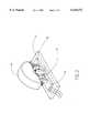
- FIG. 1shows the perspective view of the page-turning means according to the present invention
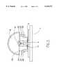
- FIG. 2shows the combinational view of the page-turning means according to the present invention
- FIG. 3shows the front view of the page-turning means according to the present invention
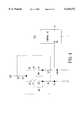
- FIG. 4shows the equivalent circuit of the page-turning means according to the present invention
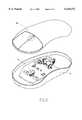
- FIG. 5shows the application of the page-turning means according to the present invention to a mouse
- FIG. 6shows the appearance of mouse equipped with the page-turning means according to the present invention.
- the page-turning meanscomprises a retaining stage 1, a base plate 2, a spring member 3 for providing a rebounding force, and a semi-circular wheel 4. More particularly, the base plate 2 (printed circuit board) is arranged on the top of the retaining stage 1. Two supporting poles 11 are arranged on both sides of the base plate 2. Each supporting pole 11 has been provided with a groove 12 on top thereof for the engagement of the shaft 41 of the semi-circular wheel 4.
- the base plate 2has an electronic circuit comprising resistors R1-R3 and three terminals 25-27, elastic plates 21-24 functioning as switch, and a T-shaped spring member 3. As shown in FIG. 4, the voltage change caused by the switches 21-24 can be sent to the control IC through the terminal 26 (27) of the base plate 2. As shown in FIG. 4, one end of the resistor R1 is connected to power source V cc and first terminal 25, another end thereof is connected to the bottom of the spring member 3. One end of the resistor R2 is connected to the first elastic plate 21 and another end thereof is connected to the second elastic plate 22 and the second terminal 26, One end of the resistor R3 is connected to the third elastic plate 23, and another end thereof is connected to the fourth elastic plate 24 and the third terminal 27.
- the bottom portion of the spring member 3is soldered to the base plate 2 such that two end portions 31, 32 of the spring member 3 are placed on the top of the corresponding elastic plates 21, 23. Therefore, the end portion 31 (32) of the spring member 3 can be in contact with one elastic plate 21 (23) or simultaneously with two elastic plates 21, 22 (23, 24) when being pressed.
- the top portion of the spring member 3is in contact with the bottom of the semi-circular wheel 4, such that the spring member 3 can maintain the balance of the semi-circular wheel 4 when no external force is applied, and functions as the contact point of the switch means.
- Each of the front bottom and rear bottom side of the semi-circular wheel 4is provided with a limiting means to limit the angle of forward or backward rolling of the semi-circular wheel 4.
Landscapes
- Engineering & Computer Science (AREA)
- General Engineering & Computer Science (AREA)
- Theoretical Computer Science (AREA)
- Human Computer Interaction (AREA)
- Physics & Mathematics (AREA)
- General Physics & Mathematics (AREA)
- Adjustable Resistors (AREA)
Abstract
Description
Claims (4)
Priority Applications (1)
| Application Number | Priority Date | Filing Date | Title |
|---|---|---|---|
| US09/108,216US6144372A (en) | 1998-07-01 | 1998-07-01 | System employing semi-circular wheel for adjustably actuating electron page advancement |
Applications Claiming Priority (1)
| Application Number | Priority Date | Filing Date | Title |
|---|---|---|---|
| US09/108,216US6144372A (en) | 1998-07-01 | 1998-07-01 | System employing semi-circular wheel for adjustably actuating electron page advancement |
Publications (1)
| Publication Number | Publication Date |
|---|---|
| US6144372Atrue US6144372A (en) | 2000-11-07 |
Family
ID=22320932
Family Applications (1)
| Application Number | Title | Priority Date | Filing Date |
|---|---|---|---|
| US09/108,216Expired - Fee RelatedUS6144372A (en) | 1998-07-01 | 1998-07-01 | System employing semi-circular wheel for adjustably actuating electron page advancement |
Country Status (1)
| Country | Link |
|---|---|
| US (1) | US6144372A (en) |
Cited By (7)
| Publication number | Priority date | Publication date | Assignee | Title |
|---|---|---|---|---|
| US20020036660A1 (en)* | 1998-09-14 | 2002-03-28 | Adan Manolito E. | Input device with forward/backward control |
| EP1324363A3 (en)* | 2001-12-25 | 2005-02-16 | Kabushiki Kaisha Tokai-Rika-Denki-Seisakusho | Mirror switch device |
| US20050206619A1 (en)* | 1999-04-06 | 2005-09-22 | Microsoft Corporation | Computer input device with digit support and natural position actuators |
| US20060192764A1 (en)* | 2005-02-28 | 2006-08-31 | Microsoft Corporation | Navigation wheel having switching assembly |
| US20070051597A1 (en)* | 2005-09-05 | 2007-03-08 | Alps Electric Co., Ltd. | Switch device and steering switch device using the same |
| US20090046064A1 (en)* | 2007-08-17 | 2009-02-19 | Microsoft Corporation | Pointing device for control of a graphical display or application |
| US7535464B1 (en) | 2004-08-30 | 2009-05-19 | Microsoft Corporation | Navigation wheel having discrete switches |
Citations (13)
| Publication number | Priority date | Publication date | Assignee | Title |
|---|---|---|---|---|
| US4159417A (en)* | 1977-10-28 | 1979-06-26 | Rubincam David P | Electronic book |
| US5179648A (en)* | 1986-03-24 | 1993-01-12 | Hauck Lane T | Computer auxiliary viewing system |
| US5313229A (en)* | 1993-02-05 | 1994-05-17 | Gilligan Federico G | Mouse and method for concurrent cursor position and scrolling control |
| US5418549A (en)* | 1993-06-14 | 1995-05-23 | Motorola, Inc. | Resolution compensating scroll bar valuator |
| US5530455A (en)* | 1994-08-10 | 1996-06-25 | Mouse Systems Corporation | Roller mouse for implementing scrolling in windows applications |
| US5801713A (en)* | 1995-05-23 | 1998-09-01 | Nec Corporation | Data browsing apparatus and method therefor including automatic page-turning |
| US5808568A (en)* | 1997-02-27 | 1998-09-15 | Primax Electronics, Ltd. | Finger operated module for generating encoding signals |
| US5825353A (en)* | 1995-04-18 | 1998-10-20 | Will; Craig Alexander | Control of miniature personal digital assistant using menu and thumbwheel |
| US5912661A (en)* | 1997-01-14 | 1999-06-15 | Microsoft Corp. | Z-encoder mechanism |
| US5917473A (en)* | 1996-09-27 | 1999-06-29 | Primax Electronics Ltd. | Encoder module for use in cursor control device |
| US5963197A (en)* | 1994-01-06 | 1999-10-05 | Microsoft Corporation | 3-D cursor positioning device |
| US5963195A (en)* | 1996-12-19 | 1999-10-05 | International Business Machines Corporation | Hardware-selectable mouse movement |
| US6014130A (en)* | 1998-01-20 | 2000-01-11 | Primax Electronics Ltd. | Mouse encoding device |
- 1998
- 1998-07-01USUS09/108,216patent/US6144372A/ennot_activeExpired - Fee Related
Patent Citations (13)
| Publication number | Priority date | Publication date | Assignee | Title |
|---|---|---|---|---|
| US4159417A (en)* | 1977-10-28 | 1979-06-26 | Rubincam David P | Electronic book |
| US5179648A (en)* | 1986-03-24 | 1993-01-12 | Hauck Lane T | Computer auxiliary viewing system |
| US5313229A (en)* | 1993-02-05 | 1994-05-17 | Gilligan Federico G | Mouse and method for concurrent cursor position and scrolling control |
| US5418549A (en)* | 1993-06-14 | 1995-05-23 | Motorola, Inc. | Resolution compensating scroll bar valuator |
| US5963197A (en)* | 1994-01-06 | 1999-10-05 | Microsoft Corporation | 3-D cursor positioning device |
| US5530455A (en)* | 1994-08-10 | 1996-06-25 | Mouse Systems Corporation | Roller mouse for implementing scrolling in windows applications |
| US5825353A (en)* | 1995-04-18 | 1998-10-20 | Will; Craig Alexander | Control of miniature personal digital assistant using menu and thumbwheel |
| US5801713A (en)* | 1995-05-23 | 1998-09-01 | Nec Corporation | Data browsing apparatus and method therefor including automatic page-turning |
| US5917473A (en)* | 1996-09-27 | 1999-06-29 | Primax Electronics Ltd. | Encoder module for use in cursor control device |
| US5963195A (en)* | 1996-12-19 | 1999-10-05 | International Business Machines Corporation | Hardware-selectable mouse movement |
| US5912661A (en)* | 1997-01-14 | 1999-06-15 | Microsoft Corp. | Z-encoder mechanism |
| US5808568A (en)* | 1997-02-27 | 1998-09-15 | Primax Electronics, Ltd. | Finger operated module for generating encoding signals |
| US6014130A (en)* | 1998-01-20 | 2000-01-11 | Primax Electronics Ltd. | Mouse encoding device |
Cited By (19)
| Publication number | Priority date | Publication date | Assignee | Title |
|---|---|---|---|---|
| US20060038786A1 (en)* | 1998-09-14 | 2006-02-23 | Microsoft Corporation | Input device with forward/backward control |
| US20060050057A1 (en)* | 1998-09-14 | 2006-03-09 | Microsoft Corporation | Input device with forward/backward control |
| US7656389B2 (en) | 1998-09-14 | 2010-02-02 | Microsoft Corporation | Input device with forward/backward control |
| US20050088414A1 (en)* | 1998-09-14 | 2005-04-28 | Microsoft Corporation | Input device with forward/backward control |
| US20100127985A1 (en)* | 1998-09-14 | 2010-05-27 | Microsoft | Input device with forward/backward control |
| US20020036660A1 (en)* | 1998-09-14 | 2002-03-28 | Adan Manolito E. | Input device with forward/backward control |
| US20020054023A1 (en)* | 1998-09-14 | 2002-05-09 | Adan Manolito E. | Input device with forward/backward control |
| US7283121B2 (en) | 1998-09-14 | 2007-10-16 | Microsoft Corporation | Input device with forward/backward control |
| US7639235B2 (en) | 1998-09-14 | 2009-12-29 | Microsoft Corporation | Input device with forward/backward control |
| US9069395B2 (en) | 1998-09-14 | 2015-06-30 | Microsoft Technology Licensing, Llc | Input device with forward/backward control |
| US7002552B1 (en)* | 1999-04-06 | 2006-02-21 | Microsoft Corporation | Computer input device with digit support and natural position actuators |
| US7345674B2 (en) | 1999-04-06 | 2008-03-18 | Microsoft Corporation | Computer input device with digit support and natural position actuators |
| US20050206619A1 (en)* | 1999-04-06 | 2005-09-22 | Microsoft Corporation | Computer input device with digit support and natural position actuators |
| EP1324363A3 (en)* | 2001-12-25 | 2005-02-16 | Kabushiki Kaisha Tokai-Rika-Denki-Seisakusho | Mirror switch device |
| US7535464B1 (en) | 2004-08-30 | 2009-05-19 | Microsoft Corporation | Navigation wheel having discrete switches |
| US20060192764A1 (en)* | 2005-02-28 | 2006-08-31 | Microsoft Corporation | Navigation wheel having switching assembly |
| US7381912B2 (en)* | 2005-09-05 | 2008-06-03 | Alps Electric Co., Ltd. | Switch device and steering switch device using the same |
| US20070051597A1 (en)* | 2005-09-05 | 2007-03-08 | Alps Electric Co., Ltd. | Switch device and steering switch device using the same |
| US20090046064A1 (en)* | 2007-08-17 | 2009-02-19 | Microsoft Corporation | Pointing device for control of a graphical display or application |
Similar Documents
| Publication | Publication Date | Title |
|---|---|---|
| US6850221B1 (en) | Trigger operated electronic device | |
| EP0463856B1 (en) | A device for scanning the menus of a telephone set | |
| US4827243A (en) | Improved structure of computer keyboard and circuit board | |
| US6144372A (en) | System employing semi-circular wheel for adjustably actuating electron page advancement | |
| US6616534B2 (en) | Button control for use in a game controller | |
| US6717568B1 (en) | Method of controlling the movement of a position indicating item, storage medium on which a program implementing said method is stored, and electronic device | |
| JP2000517463A (en) | Digital switch with analog feeling | |
| JP2770962B2 (en) | Push button switch device | |
| EP0444757B1 (en) | Power on/off circuit with lock function | |
| MXPA04007108A (en) | Current sensing methods and apparatus in an appliance. | |
| CA2292222A1 (en) | Time switch | |
| KR0132212Y1 (en) | Elevator switch control circuit | |
| EP1026828B1 (en) | Generating a control signal for an electrical device with the aid of keys | |
| KR940015728A (en) | Controller | |
| JP2737670B2 (en) | Encoder circuit | |
| JPH0220738Y2 (en) | ||
| JP2007173167A (en) | Switching device with electrostatic detecting function | |
| JP3491494B2 (en) | Operation switch holding device | |
| JPH0713308Y2 (en) | Frequency setting device using joystick | |
| JP2699561B2 (en) | Conductive object detection device | |
| JPS5918747Y2 (en) | Three-value output generation circuit | |
| EP1193656A3 (en) | Switching circuit for generating a switch-on signal for battery-powered coin testers | |
| KR100237943B1 (en) | Signal generator using magnetic force | |
| JP2003173233A (en) | Erroneous operation reducing structure of multidirectional key of electronic equipment | |
| JPH1097360A (en) | Command input device and portable information input device |
Legal Events
| Date | Code | Title | Description |
|---|---|---|---|
| AS | Assignment | Owner name:DEXIN CORPORATION, TAIWAN Free format text:ASSIGNMENT OF ASSIGNORS INTEREST;ASSIGNOR:CHEN, CHENG HSIUNG;REEL/FRAME:009303/0668 Effective date:19980619 | |
| FPAY | Fee payment | Year of fee payment:4 | |
| FPAY | Fee payment | Year of fee payment:8 | |
| AS | Assignment | Owner name:WEN CAPITAL, LLC, DELAWARE Free format text:ASSIGNMENT OF ASSIGNORS INTEREST;ASSIGNOR:DEXIN CORPORATION;REEL/FRAME:021744/0550 Effective date:20080923 | |
| FEPP | Fee payment procedure | Free format text:PAYER NUMBER DE-ASSIGNED (ORIGINAL EVENT CODE: RMPN); ENTITY STATUS OF PATENT OWNER: LARGE ENTITY Free format text:PAT HOLDER NO LONGER CLAIMS SMALL ENTITY STATUS, ENTITY STATUS SET TO UNDISCOUNTED (ORIGINAL EVENT CODE: STOL); ENTITY STATUS OF PATENT OWNER: LARGE ENTITY Free format text:PAYOR NUMBER ASSIGNED (ORIGINAL EVENT CODE: ASPN); ENTITY STATUS OF PATENT OWNER: LARGE ENTITY | |
| FEPP | Fee payment procedure | Free format text:PAYER NUMBER DE-ASSIGNED (ORIGINAL EVENT CODE: RMPN); ENTITY STATUS OF PATENT OWNER: LARGE ENTITY Free format text:PAYOR NUMBER ASSIGNED (ORIGINAL EVENT CODE: ASPN); ENTITY STATUS OF PATENT OWNER: LARGE ENTITY | |
| REMI | Maintenance fee reminder mailed | ||
| LAPS | Lapse for failure to pay maintenance fees | ||
| STCH | Information on status: patent discontinuation | Free format text:PATENT EXPIRED DUE TO NONPAYMENT OF MAINTENANCE FEES UNDER 37 CFR 1.362 | |
| FP | Lapsed due to failure to pay maintenance fee | Effective date:20121107 | |
| AS | Assignment | Owner name:HANGER SOLUTIONS, LLC, GEORGIA Free format text:ASSIGNMENT OF ASSIGNORS INTEREST;ASSIGNOR:INTELLECTUAL VENTURES ASSETS 158 LLC;REEL/FRAME:051486/0425 Effective date:20191206 | |
| AS | Assignment | Owner name:INTELLECTUAL VENTURES ASSETS 158 LLC, DELAWARE Free format text:ASSIGNMENT OF ASSIGNORS INTEREST;ASSIGNOR:WEN CAPITAL, LLC;REEL/FRAME:051760/0254 Effective date:20191126 |