US6143945A - Bandage for autolytic wound debridement - Google Patents
Bandage for autolytic wound debridementDownload PDFInfo
- Publication number
- US6143945A US6143945AUS09/056,121US5612198AUS6143945AUS 6143945 AUS6143945 AUS 6143945AUS 5612198 AUS5612198 AUS 5612198AUS 6143945 AUS6143945 AUS 6143945A
- Authority
- US
- United States
- Prior art keywords
- wound
- fluid
- skin
- bandage
- enclosure
- Prior art date
- Legal status (The legal status is an assumption and is not a legal conclusion. Google has not performed a legal analysis and makes no representation as to the accuracy of the status listed.)
- Expired - Lifetime
Links
Images


Classifications
- A—HUMAN NECESSITIES
- A61—MEDICAL OR VETERINARY SCIENCE; HYGIENE
- A61F—FILTERS IMPLANTABLE INTO BLOOD VESSELS; PROSTHESES; DEVICES PROVIDING PATENCY TO, OR PREVENTING COLLAPSING OF, TUBULAR STRUCTURES OF THE BODY, e.g. STENTS; ORTHOPAEDIC, NURSING OR CONTRACEPTIVE DEVICES; FOMENTATION; TREATMENT OR PROTECTION OF EYES OR EARS; BANDAGES, DRESSINGS OR ABSORBENT PADS; FIRST-AID KITS
- A61F13/00—Bandages or dressings; Absorbent pads
- A61F13/02—Adhesive bandages or dressings
- A61F13/0203—Adhesive bandages or dressings with fluid retention members
- A61F13/0226—Adhesive bandages or dressings with fluid retention members characterised by the support layer
- A—HUMAN NECESSITIES
- A61—MEDICAL OR VETERINARY SCIENCE; HYGIENE
- A61F—FILTERS IMPLANTABLE INTO BLOOD VESSELS; PROSTHESES; DEVICES PROVIDING PATENCY TO, OR PREVENTING COLLAPSING OF, TUBULAR STRUCTURES OF THE BODY, e.g. STENTS; ORTHOPAEDIC, NURSING OR CONTRACEPTIVE DEVICES; FOMENTATION; TREATMENT OR PROTECTION OF EYES OR EARS; BANDAGES, DRESSINGS OR ABSORBENT PADS; FIRST-AID KITS
- A61F13/00—Bandages or dressings; Absorbent pads
- A61F13/02—Adhesive bandages or dressings
- A61F13/0203—Adhesive bandages or dressings with fluid retention members
- A61F13/0206—Adhesive bandages or dressings with fluid retention members with absorbent fibrous layers, e.g. woven or non-woven absorbent pads or island dressings
- A—HUMAN NECESSITIES
- A61—MEDICAL OR VETERINARY SCIENCE; HYGIENE
- A61F—FILTERS IMPLANTABLE INTO BLOOD VESSELS; PROSTHESES; DEVICES PROVIDING PATENCY TO, OR PREVENTING COLLAPSING OF, TUBULAR STRUCTURES OF THE BODY, e.g. STENTS; ORTHOPAEDIC, NURSING OR CONTRACEPTIVE DEVICES; FOMENTATION; TREATMENT OR PROTECTION OF EYES OR EARS; BANDAGES, DRESSINGS OR ABSORBENT PADS; FIRST-AID KITS
- A61F13/00—Bandages or dressings; Absorbent pads
- A61F2013/00089—Wound bandages
- A61F2013/00165—Wound bandages not touching the wound
Definitions
- the inventionconcerns the removal of dead tissue from a wound and more particularly, a bandage that promotes the removal of dead tissue by substances that the body itself produces.
- Chronic woundsare a common aliment, afflicting over 5 million people annually in this country. The majority of chronic wounds are caused by a local or generalized vascular insufficiency that reduces blood flow to the skin and subcutaneous tissue. The most common type of chronic wounds include: pressure ulcers (decubiti, or "bed sores"); diabetic ulcers; arterial ulcers; venous ulcers, or a combination of these. Chronic wounds are full-thickniess skin injuries that may be very large and that may persist for months or years.
- chronic woundsfrequently exude large olumes of fluid.
- this fluidmay primarily be a serious transudate consisting of plasma and interstitial fluid.
- the fluidwill contain many white blood cells, cellular debris, and toxic cellular metabolic waste products. Such fluid is commonly denominated as "exudate" or "pus".
- the goal of wound managementis to keep a wound moist. This may be accomplished by trapping exudate or transudate in a wound bed under a substantially fluid-impermeable bandage. This practice avoids drying a wound, but leads to a new problem.
- larger amounts of fluid from moderate or heavily exudating woundsmay result in a pool of trapped fluid under the bandage.
- This pool of fluidis in constant contact with the wound and the peri-wound skin, which is a margin of skin that surrounds and abuts the wound.
- the wound and peri-wound tissuesare constantly wet, which can lead to maceration and further damage.
- the fluidcontains cellular debris and metabolic waste products that may be toxic to the living tissue of the wound bed and peri-wound. The toxicity of the fluid may retard wound healing and, indeed, may damage healthy peri-wound tissue and already healed wound tissue.
- Autolytic debridemenetdenotes the body's natural ability to break down dead tissue, thereby continuously cleaning a wound so that new skin cells can grow to fill and cover the wound, thereby promoting its healing.
- autolyticrefers to the destruction of dead tissue by agents produced by the body.
- Deliveryis the removal of dead cells or tissue from a wound. Autolytic debridement is therefore the breaking down and removal of dead tissue from a wound by substances and processes that are natural to the body. This function is carried out by white blood cells generally known as phagocytes, and by a variety of enzymes.
- autolytic debridementis an autogenic process, driven by the functioning of body systems, it is affected by temperature.
- hypothermiais known to slow or even stop cellular functions, immune system functions, enzyme reactions, and biochemical processes.
- Effective phagocytosisrequires an active immune system, active cellular functions, and rapid enzyme and biochemical reactions.
- Many wounds, because of their locations on body limbs,are hypothermic. The cool environment of these wounds slows down the process of autolytic debridement, extending the time required for healing.
- the need for a device to keep a wound area humid, but not wetis compounded by the need for the device to enhance autolytic debridement by carrying exudate away from the wound and keeping the wound warm.
- Our inventionembraces at least two components.
- Firstis a non-contact bandage with an outer shell that creates an enclosure over and about a wound, that does not touch the wound.
- the enclosureincludes an adhesive attachment means that adhesively attaches the bandage to the skin around the wound, forming a chamber that is substantially sealed over the wound.
- the inventionis a bandage for autolytic debridement that includes a fluid-impermeable enclosure having a sidewall forming a margin that defines an opening, and a skin-facing surface extending beyond the margin away from the opening.
- An attachment meansis disposed on the skin-facing surface for attaching the enclosure to skin to create a closed, fluid-impermeable chamber over a wound, substantially without contacting the wound.
- a fluid absorbent materialis disposed in the fluid-impermeable enclosure substantially at or near the margin and out of the opening.
- FIG. 1is an isometric drawing of a first embodiment of a bandage for autolytic debridement.
- FIG. 1Ais an isometric section taken along A--A in FIG. 1.
- FIG. 1Bis an enlarged partial side sectional view of a portion of the isometric section shown in FIG. 1A.
- FIG. 2is an isometric drawing of a second embodiment of a bandage for autolytic debridement.
- FIG. 2Ais an isometric section taken along A--A of FIG. 2.
- FIG. 2Bis a partial side sectional view showing details of the isometric section of FIG. 2A.
- FIGS. 2C and 2Dare side sectional views showing variations in the structure and elements of the second embodiment.
- FIG. 3is an isometric section view of a third embodiment of a bandage for autolytic debridement.
- FIG. 3Ais a side sectional view taken along A--A of FIG. 3.
- FIG. 4is an isometric drawing of a fourth embodiment of a bandage for autolytic debridement.
- FIG. 4Ais a side sectional view taken along A--A of FIG. 4.
- FIG. 5is an isometric drawing of a fifth embodiment of a bandage for autolytic debridement.
- FIG. 5Ais a side sectional view taken along A--A of FIG. 5.
- FIG. 6is an isometric drawing of a sixth embodiment of a bandage for autolytic debridement.
- FIG. 6Ais a side sectional view taken along A--A of FIG. 6.
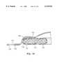
- FIG. 7is an isometric section illustrating a seventh embodiment of a bandage for autolytic debridement.
- FIG. 7Ais a side sectional view taken along A--A of FIG. 7.
- the bandageincludes a fluid-impermeable enclosure having a sidewall that forms a margin defining an opening, and a skin-facing surface surrounding the opening.
- An attachment meansis disposed on the skin-facing surface to attach the enclosure to the skin, with the margin extending outside of and surrounding at least the bed of a wound, if not an annulus of peri-wound tissue around the wound.
- the bandageincludes a fluid absorbent material disposed in the fluid-impermeable enclosure, at or near the continuous margin, and out of the opening.
- the fluid absorbent materialis thus positioned to receive and retain exuded fluid that originates in the wound.
- the closed, fluid-impermeable chambermaintains a near-100% humid atmosphere about the wound.
- the humid atmosphere and the structure of the bandagetend to maintain the temperature of the atmosphere about the wound at or near a normothermic level in the range of about 36° C. to about 38° C.
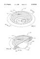
- the bandage 10includes an enclosure 12 having the shape of an iniverted saucer with a depression 14 defined by a sidewall 16 that has the shape of an annulus, preferably a continuous annulus.
- the sidewall 16transitions to a compressed ring 18.
- the lower inside surface of the sidewall 16defines an inner margin 20.
- the outside edge of the compressed ring 18defines an outer margin 22.
- the inner and outer marginsare preferably, but not necessarily continuous and circular in shape.
- a fluid-impermeable barrier 26having the shape of a ring extends continuously on a lower surface portion of the sidewall 16 and the compressed ring 18.
- the fluid-impermeable barrier 26provides a skin-facing surface 27 of the bandage 10 on which is disposed a ring of adhesive material 28.
- the ring ot adhesive material 28may have a release liner on its lower surface which is stripped away when the bandage 10 is to be attached to the skin of a patient.
- the bandage 10is attached to the skin of a patient by the ring of adhesive material 28 such that the sidewall 16 and the inner margin 20 define an opening 23 that surrounds the bed of a wound 30 and a ring of peri-wound tissue 32 immediately adjacent to the wound 30. Above the opening 23, the space in the depression 14 forms a closed, dome-like structure over the wound 30 which spans the wound 30 without contacting it.
- the enclosure 12, the sidewall 16, and the compressed ring 18are formed integrally.
- the integral structureis formed of a material that is light, flexible, yet of a nature that provides structural integrity to the bandage 10, allowing it to stand upright when attached as shown in the figures.
- the bandage 10may be formed by molding open cell foam material such as polyurethane. The material is compressed to form the compressed ring 18 only for the purpose of profiling the bandage 10. Such profiling is not a necessary element of the invention.
- the molded open cell foam materialis also fluid absorbent. However the outer surface of the molded open cell foam material is treated to make it moisture impermeable.
- the outer surface of the bandage 10may be "skunned" by mechanical or heat means that are well known in the art.
- a continuous film of moisture-impermeable materialmay be attached or laminated to the outside surface of the bandage 10.
- the inside surface of the bandage 10, that is the surface of the molded open cell foam material that forms the depression 14, the lower surface of the sidewall 16, and the inner margin 20is not treated in the manner of the outside surface of the bandage 10.
- the inside surface of the bandage over, about, and surrounding the wound 30is fluid permeable, permitting exudate from the wound 30 to pass through the inside surface of the bandage 10 into the fluid absorbent material of which the bandage 10 is formed.
- the barrier film layer 26is fluid impermeable for the purpose of preventing fluid which has been absorbed by the fluid absorbent material from moistening healthy skin underneath the skin facing surface 27 and the ring of adhesive material 28.
- the entire bottom surface of the sidewallcould be made fluid impermeable, in which case the barrier film layer would be eliminated and the skin-facing, surface 27 would be the bottom surface of the sidewall 16.
- the ring of adhesive material 28would be mounted directly to the bottom surface of the sidewall 16. In operation, the ring of adhesive material 28 is prepared for attachment to the skin surface, and the bandage 10 is attached via the ring of adhesive material 28 to the skin surface, positioned so that the inner margin 20 surrounds the wound 30, set back from the peri-wound area 32.
- the bandage 10has a measurable moisture vapor transmission rate (MVTR), which is slight compared to the amount of fluid exuded from the wound 30.
- MVTRmoisture vapor transmission rate
- the sealed enclosure formed by the bandage 10has three purposes. First, it absorbs exudate produced at the wound 30, retaining most if not all not it in the molded open cell foam material through the inside surface of the bandage 10. This eliminates pooling of exudate in the wound and promotes autolytic debridement. This also prevents contamination and the spread of pathogens and odors. Second, the bandage 10 maintains an environment of high relative humidity over the wound 30. Finally, the sealed enclosure and its humid atmosphere effectively thermally insulate the wound and peri-wound area from the ambient environment, which tends to maintain the temperature of wound and peri-wound area in a normothermic range of from about 36° C. to about 38° C.
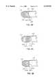
- FIGS. 2 and 2A-2Dillustrate a second embodiment of a bandage for autolytic debridement according to our invention.
- the bandage 210includes a sidewall 216 that has the shape of an torus, preferably a continuous torus.
- a disk-shaped cover 215is attached or bonded to one side of the torus, over its center.
- the cover 215 and sidewall 216form an enclosure having the shape of a doughnut with a cover on one side.
- the sidewall 216has an inner surface 217 that transitions to a lip 218.
- the lip 218projects inwardly into the opening of the torus formed by the sidewall 216.
- the front edge of the lip 218forms an inner margin 220.
- the inner marginis preferably, but not necessarily, continuous and circular in shape.
- the inner margin 220defines an opening 223.
- a side surface of the torus formed by the sidewall 216constitutes a skin-facing surface 224.
- a ring of adhesive material 228is disposed on the skin-facing surface 224.
- the ring of adhesive material 228may have a release liner on its lower surface which is stripped away when the bandage 210 is to be attached to the skin of the patient.
- the bandage 210is attached to the skin of a patient by the ring of adhesive material 228 such that the sidewall 216 and the inner margin 220 define an opening 223 that surrounds the bed of a wound 230 and a ring of peri-wound tissue 232 immediately adjacent the wound 230.
- the space defined by the inner wall 217 of the sidewall 216 and the cover 215forms a closed structure over the wound 230 which spans the wound 230) without contacting it.
- the cover 215 and sidewall 216are formed as separate single pieces.
- the sidewallis formed of a material that is light, flexible, yet of nature that provides structural integrity to the bandage 210, allowing it to stand upright when attached as shown in the figures.
- the sidewall 216may be formed by molding open cell foam material such as polyurethane. The molding process forms the sidewall 216 into the shape that includes the inward facingo lip 218 that transitions to the inner margin 220.
- the molded open cell foam materialis fluid absorbent.
- the cover 215may comprise a thin sheet of flexible, transparent plastic material that may be bonded by a continuous fluid-impervious seal, for example, by adhesive, to the sidewall 216 in the manner shown in the figures.
- the cover 215may comprise a 4 mil-thick sheet of polyethylene.
- the inside surface 217 of the bandage 210is not treated in the manner of the outside surface of the bandage 210. In this regard, the inside surface 217 is fluid permeable, permitting exudate from the wound 230 to be absorbed into the fluid-absorbent material of which the bandage 210 is formed.
- the fluid-impermeable treatment of the outer surface of the sidewall 216extends to the skin-facing surface 224, making that surface fluid-impermeable and preventing fluid which has been absorbed by he side wall 216 through the inner surface 217 from moistening healthy skin underneath the skin-facing surface 224 and the ring of adhesive 228.
- the ring of adhesive material 228is prepared for attachment to the skin surface, and the bandage 210 is attached via the ring of adhesive material 228 to the skin surface, positioned so that the inner margin 220 surrounds the wound 230, set back from the peri-wound area 232.
- the MVTR through the bandage 210is slight compared to the amount of fluid exuded from the wound 230.
- the lip 218provides contour that promotes the flow of fluid exuded from the wound 230 upward along the surface 217.
- the inner margin 220may be provided on contours other than the curved lip 218 of FIGS. 2A and 2B.
- the sidewall 216may be shaped to provide an inner surface 217a that is rounded outwardly of the torus shape so that the inner margin 220a is provided where the fluid permeable inner surface 217a transitions to the fluid-impermeable skin-facing surface 224.
- the sidewall 216is shaped with a straight, flat inner surface 217b that is fluid permeable. In this case, the inner margin 220b is provided along the bottom edge of the inner surface 217b.
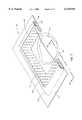
- FIGS. 3 and 3Aillustrate a third embodiment of a bandage for autolytic debridement according to our invention.
- the bandage 310has a sidewall 316 in the form of a pouch having the overall shape of square or rectangular annulus.
- the pouch of which the sidewall 316 is comprisedhas a generally rectangular cross-section with rounded ends 316a and 316b.
- Being a pouchsidewall 316 has an interior space.
- a cover 315is attached to an upper surface 321 of the sidewall 316, continuously around the sidewall 316 to form an enclosure therewith.
- the sidewall 316has an inner side surface 317 and the surface 321 has an interior surface portion 321a.
- Holes 319are provided through the inner surface portion 321a and the inner surface 317.
- the holes(or apertures or ports) open into the interior space of the pouch of which the sidewall 316 is comprised.
- An inner margin 320which is preferably but not necessarily continuous, defines an opening 323.
- the interior space of the pouch of which the sidewall 316 is comprisedis filled with a fluid-absorbent material 325.
- the bottom of the sidewall 316has a skin-facing surface 327 that is unapertured.
- a square or rectangular annulus of adhesive material 328is disposed on this skin-facing surfacing 327.
- the adhesive material 328may have a release liner on its lower surface which is stripped away when the bandage 310 is to be attached to the skin of a patient.
- the bandage 310is attached to the skin of a patient by the ring of adhesive 328 such that the sidewall 316 and the inner margin 320 define the opening 323 with the opening 323 surrounding the bed of a wound 330 and ring of peri-wound tissue 332.
- the cover 315exhibits an upwardly rising, dome-like structure that rises above the inner surface portion 321a in order not to occlude the holes 319 in that inner surface portion.
- the cover 315 and sidewall 316form an enclosure over the wound 330 which spans the wound 330 without contacting it.
- the cover 315is formed of a sturdy, yet somewhat flexible, moisture-impermeable, desirably (but not necessarily) transparent material.
- the materialshould be sturdy enough to form and maintain the dome that rises over the opening 323. Flexibility is necessary to accommodate various contours that are encountered on the surface of a body.
- the cover 315may comprise a 4 mil-thick sheet of molded polystyrene or polyester or polyvinylchloride or equivalent material that is attached or bonded by a continuous, closed seam acting between the surface 321 of the sidewall 316 in the outer periphery of the cover 315.
- the bond that joins the cover 315 with the sidewall 316may be a permanent bond, or an adhesive seam that permits the cover 315 to be removed from the sidewall 316.
- the sidewall 316may be formed of the same material as the cover 315.
- the sidewall 316When filled with the fluid-absorbent material 325, the sidewall 316 provides a light, flexible structure that affords structural integrity to the bandage 310, allowing it to stand upright when attached as shown in the figures.
- the fluid-absorbent material 325 that fills the interior of the sidewall 316may comprise, for example, an alginate.
- the inside surface 317 and the inner surface portion 321aboth of which are apertured, provide ingress to fluid, permitting exudate from the wound 330 to flow into the interior space of the sidewall 316 there to be absorbed and retained by the fluid absorbent material 325. Since the surfaces 321 and 327 are unapertured, fluid that is absorbed by the fluid-absorbent material 325 is prevented from moistening healthy skin underneath the skin-facing surface 327 and the ring of adhesive 328. In operation, the ring of adhesive 328 is prepared for attachment to the skin surface, and bandage 310 is attached via the ring of adhesive 328 to the skin surface, positioned so that the inner margin 320 surrounds the wound 330, set back from the peri-wound area 332.
- the material of which the cover 315 and sidewall 316 are formedprovides a measurable MVTR, which is slight compared to the amount of fluid exuded from the wound 330.
- the bandage 410includes a cover 412 that is circularly shaped and molded to form an enclosure with a flattened dome. At its margin, the cover 412 transitions to a lip 413, on the bottom of which is a first skin-facing surface 414.
- a sidewall 416has the shape of an annulus, preferably a continuous annulus that includes an inner ring of material 417 and an outer ring of material 419. The bottom surface of the inner ring of material 417 is a second skin facing surface 418.
- An inner margin 420defines an inner circumference of the inner ring of material 417.
- An inner surface 421rises from the inner margin 420.
- the sidewall 416 and the inner margin 420define an opening 423.
- One or more grooves 425extend radially on the upper surface of the sidewall 416 extending from the top of the inner surface 421 to the outer periphery of the sidewall 416, traversing both the inner and outer rings of material 417 and 419.
- a ring of adhesive material 428is disposed on the first skin-facing surface 414.
- the ring of adhesive material 428may have a release liner on its lower surface which is stripped away when the bandage 410 is to be attached to the skin of the patient.
- the bandage 410is attached to the skin of a patient by the ring of adhesive material 428 such that the opening 423 defined by the sidewall 416 and the inner margin 420 surrounds the bed of a wound 430 and a ring of peri-wound tissue 432 immediately adjacent to the wound 430.
- a closed spaceis defined over the wound 430 by the sidewall 416 and the cover 412.
- the cover 412 and sidewall 416may be formed as separate single pieces.
- the sidewallis formed of two materials, both light, flexible, yet of a nature that provides structural integrity to support the cover 412 upright over the wound 430 when attached as shown in the figures.
- the sidewall 416is preferably a single integral piece that unifies the inner ring of material 417 and the outer ring of material 419.
- the inner ring of material 417is, preferably, a fluid absorbent material such as a molded open cell foam.
- the second skin-facing surface 418is treated so as to be fluid impermeable.
- the inner surface 421 and the upper surface of the inner ring of material 417are fluid permeable.
- the outer ring of material 419is preferably a fluid impermeable material such as molded closed cell foam.
- the inner and outer rings of material 417 and 419may both be fluid absorbent, yet exhibit different degrees of absorbency.
- the inner ring of material 417may comprise a very open porous material into which thick, viscous exudate is readily absorbed.
- the outer ring of material 219may comprise a somewhat less open material into which thinners less viscous exudate is received.
- the inner and outer rings of material 417 and 419may be molded separately and bonded together or formed in a multi-step molding process.
- the cover 412may comprise a thin molded sheet of flexible, transparent plastic material that may be bonded by a continuous fluid-impervious seal (for example adhesive) to the sidewall 416 in the manner shown in the figures.
- the bond that joins the cover 412 with the sidewall 416may be a permanent bond, or an adhesive seam the permits the cover 412 to be removed from the sidewall 416.
- the cover 415may comprise a molded 4 mil-thick sheet of polyethylene or equivalent material. Since the inside surface 421 of the sidewall 416 is fluid permeable, it permits exudate from the wound 430 to be absorbed into the fluid-absorbent material of the inner ring of material 417. However, the fluid-impermeable treatment of the second skin-facing surface 418 and the fluid-impermeable material of the outer ring of material 419 prevent fluid which has been absorbed into the inner ring of material 417 from moistening healthy skin underneath or outside of the second skin-facing surface 418.
- the ring of adhesive material 428is prepared for attachment to the skin surface, and the bandage 410 is attached via the ring of adhesive material 428 to the skin surface, positioned so that the inner margin 420 surrounds the wound 430, set back from the peri-wound area 432.
- exudateis produced in the bed of the wound 430, it flows across the peri-wound area 432, contacting the molded open cell foam material of the inner ring of material 417 at, near, and above the inner margin 420 along the surface 421, where it is absorbed into the bandage 410.
- fluidevaporates from the wound 430 and the skin, increasing the relative humidity within the enclosure formed by the cover 412 and the sidewall 416 to near 100%.
- the MVTR through the bandage 410is slight compared to the amount of fluid exuded from the wound 430.
- the grooves 425provide channels that promote the flow of fluid exuded from the wound 430 along the upper surface of the sidewall 416.
- fluid from the wound 430may flow along one or more of the grooves 425 to be absorbed into the material of the inner ring of material 417.
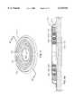
- FIGS. 5 and 5Aillustrate a fifth embodiment of a bandage for autolytic debridement according to our invention.
- the bandage 510includes a cover 512 identical to the cover 412 of the fourth embodiment illustrated in FIGS. 4 and 4A.
- the cover 512is a molded, circularly-shaped piece that has a lip 513 and first skin-facing surface 514.
- the sidewall 516 of the fifth embodiment bandageincludes a flat circular container 517 having a circumferential outer rim 518 that rises above a floor 519.
- a second skin-facing surface 520is on the bottom of the flat circular container 517.
- An inner margin 522defines an opening 523 through the floor 519 of the flat circular container 517.
- Concentric rings of material 524a and 524bare disposed within the flat circular container 517.
- the diameter of the first ring of material 524ais less than the diameter of the second ring of material 524b; both rings of material arc substantially centered in and concentric with the outer rim 518 of the flat circular container 517.
- the elements of the sidewall 516, including the flat circular container 517, the first ring of material 524a, and second ring of material 524bare all fluid absorbent, preferably made of a molded open cell foam material.
- at least the second skin-facing surface 520 of the flat circular container 517is treated as described above with reference to the first embodiment so as to be fluid impermeable.
- All surfaces of the first and second rings of material 524a and 524b and the interior surface of the flat circular container 517are not treated and are therefore fluid permeable, enabling the flow of exudate through those surfaces into the material of which their respective structures are formed.
- the flat circular container 517, the first ring of material 524a and the second ring of material 524bare an integral piece, either formed in the same or successive steps, or formed separately and bonded together.
- Conceniic channels 526 and 527are formed between the first ring of material 524a and the second ring of material 524b, and between the second ring of material 524b and the outer rim 518 of the flat circular container.
- radial channelsare formed by notches 529 formed in the first and second rings of material 524a and 524b that are aligned along a radius of the flat circular container 517.
- a ring of adhesive material 528is mounted on the first skin-facing surface 514 on the cover 512.
- the ring of adhesive material 528may have a release liner on its lower surface which is stripped away when the bandage 510 is to be attached to the skin of the patient.
- the bandage 510is attached to the skin of a patient by the ring of adhesive material 528 such that the opening 523 defined by the inner margin 522 surrounds the bed of a wound 530 and a ring of peri-wound tissue 532 immediately adjacent the wound 530.
- the space defined between the cover 512 and the sidewall 516forms a closed structure over the wound 530 which spans the wound 530 without contacting it.
- the cover 512 and sidewall 516are separate, single pieces.
- the sidewall 516is formed as described above, comprising a material that is light, flexible, yet of a nature that provides structural integrity to the bandage 510 and support to the cover 512, allowing the bandage 510 to stand up right when attached as shown in the figures.
- the cover 512may comprise the material of, and be formed as described above in connection with, the fourth embodiment.
- the cover 512may be bonded by a continuous fluid-impervious seal to the sidewall 516 in the manner shown in the figures.
- the bond that joins the cover 512 with the sidewall 516may be a permanent bond, or an adhesive seam that permits the cover 512 to be removed from the sidewall 516. Since the inside surfaces of the flat circular container 517 and all surfaces not the first and second rings 524a and 524b are fluid permeable, exudate from the wound 530 is permitted to be absorbed into the fluid absorbent material of which the flat circular container 517 and the rings 524a and 524b are formed. However, the fluid-impermeable treatment of the second skin-facing surface 520 makes that surface fluid-impermeable, thereby preventing fluid which has been absorbed into the sidewall 516 from moistening healthy skin underneath the skin-facing surface 520.
- the ring of adhesive material 528is prepared for attachment to the skin surface, and the bandage 510 is attached via the ring of adhesive material 528 to the skin surface, positioned so that the inner margin 520 surrounds the wound 530, set back from the peri-wound area 532.
- the radial channels formed by the notches 529provide ingress to the exudalt fluid into the concentric channels 526 and 527.
- the concentric channels 526 and 527conduct and distribute the fluid over the sidewalls of the rings of material 524a and 524b, the floor 519 of the flat circular container 517 and the inner wall of the outer rim 518. All of these surfaces are fluid permeable and provide a path into the fluid absorbent material of which their respectve structures are formed.
- the portion of the sidewall between the first tear line 525a and the inner margin 529may be separated entirely from and removed from the bandage 510.
- Thisprovides an opening 523 having a larger diameter then that shown in FIG. 5 and moves the inner margin 522 diametrically toward the outer rim 518.
- These tear linespermit the bandage 510 to be configured to accommodate wounds of varying sizes.
- FIGS. 6 and 6Aillustrate a sixth embodiment of a bandage for autolytic debridement according to our invention.
- the bandage 610is identical in all respects with the bandage 510 illustrated in FIGS. 5 and 5A.
- circular members 650are disposed within the sidewall 616, concentrically interspersed with the first ring of material 624a, the second ring of material 624b, and the outer rim 618 of the sidewall 616.
- Each of the circular members 650comprises a fluid absorbent material such as an alginate, hydrogel, or hydrocolloid.
- the circular members 650can comprise a wicking material.
- the circular members 650promote the transport and absorption of exudate fluid from the wound 630 and the peri-wound area 632 to and into the fluid absorbing members of the sidewall 618.
- FIGS. 7 and 7Aillustrate a seventh embodiment of a bandage for autolytic debridement according to our invention.
- the bandage 710includes a sidewall 716 that is identical in all respects with the sidewall 316 of the third embodiment illustrated in FIGS. 3 and 3A, with one exception. That exception is that the entire surface of the sidewall 716 is apertured by holes 719 that permit exudate to enter the sidewall the 716, there to be absorbed by fluid-absorbent material 725.
- a cover 715 identical in all respects with the cover 315 of the third embodiment bandage 310is sealingly bonded to the sidewall 716.
- An additional shaped or molded plastic member 750 in the shape of a square or rectangular annulus or skirtis bonded near a first edge 751 to an upper surface of the cover 715 along the periphery of the cover 715 by a continuous, fluid-impervious seal.
- the plastic member 750is shaped to transition to a lip 752, a bottom surface of which forms a skin-facing surface 753 on which is mounted a ring of adhesive material 728.
- the structure, materials and operation of the bandage 710are as described above for the bandage 310.
- the plastic member 750is more flexible than the cover 715, not needing the dome-supporting ability of that element.
- each of the seven embodiments illustrated in the figures and discussed in the specificationforms a sealed enclosure that satisfies the three purposes set forth above for the first embodiment. That is, each embodiment absorbs exudate produced at a wound, retaining most of if not all of the exudate in fluid-absorbent material that is brought into the structure of the bandage at least on an inside surface that is near a margin defining an opening about a wound. This eliminates pooling of exudate in the wound and promotes autolytic debridement. This structure also prevents contamination and the spread of pathogens and odors. Second, each embodiment of the bandage maintains an environment of high relative humidity over a wound.
- each embodimentprovides a sealed enclosure which, together with the humid atmosphere within the enclosure, effectively thermally insulates a wound and peri-wound area from an ambient environment, which tends to maintain the temperature of the wound and peri-wound area in a normothermic range of from about 36° C. to about 38° C.
- fluid-absorbent materialcomprising fluid-absorbent material.
- fluid-absorbent materialOne specific instantiation of such material has been disclosed: molded open-cell foam. This is not intended to limit the practice of our invention to the use of that specific material. Instead, any material that can provide the necessary structural features is contemplated, so long as one or more surfaces of a member made of the material can be made fluid-impermeable without limitation.
- Other fluid absorbent materialsmay include hydrogels and hydrocolloids, for example Other features may be incorporated into our invention.
- the fluid absorbing materialmay be impregnated with hydrophilic material to increase its fluid-storing capacity, with odor-absorbing material, such as charcoal, and/or with treatment material such as antibiotics or medicants.
- features, functions and/or structures described for one embodimentmay be incorporated into one or more of the other embodiments.
- he ability to detach rings in the fifth and sixth embodimentsmay be incorporated in the fourth.
- Variability in the fluid absorption characteristics of different members that was described in connection with the fourth embodimentcould be incorporated into at least the fifth and sixth, if not all of the remaining embodiments.
- a wound treatment apparatus(or “bandage” or “plaster”) having a fluid impermeable enclosure with a sidewall forming a margin that defines an opening is provided, the wound treatment apparatus including a fluid absorbent material disposed in the enclosure.
- the fluid absorbent materialis disposed at, or near the margin, out of the opening.
- the wound treatment devicealso includes an attachment device (or a means for attachment) on a skin-facing surface of the enclosure.
- the enclosureis brought against the surface of a human (or animal) body such that the attachment device attaches the wound treatment device to the surface at a location that creates a closed, substantially fluid impermeable environment over a wound, with the wound in the opening, substantially encircled by the margin.
- the closed, substantially, fluid impermeable environmentcreates a humid atmosphere within the enclosure, about the wound that maintains a temperature about the wound at or near a normothermic level in the range of about 36° C. to about 38° C. Fluid exudate produced in or near the wound is collected and held in the fluid absorbent material as the wound heals.
Landscapes
- Health & Medical Sciences (AREA)
- Engineering & Computer Science (AREA)
- Biomedical Technology (AREA)
- Heart & Thoracic Surgery (AREA)
- Vascular Medicine (AREA)
- Life Sciences & Earth Sciences (AREA)
- Animal Behavior & Ethology (AREA)
- General Health & Medical Sciences (AREA)
- Public Health (AREA)
- Veterinary Medicine (AREA)
- Materials For Medical Uses (AREA)
Abstract
Description
Claims (10)
Priority Applications (6)
| Application Number | Priority Date | Filing Date | Title |
|---|---|---|---|
| US09/056,121US6143945A (en) | 1998-04-06 | 1998-04-06 | Bandage for autolytic wound debridement |
| PCT/US1999/007449WO1999051176A1 (en) | 1998-04-06 | 1999-04-05 | Bandage for autolytic wound debridement |
| AU34706/99AAU3470699A (en) | 1998-04-06 | 1999-04-05 | Bandage for autolytic wound debridement |
| US09/363,568US6320093B1 (en) | 1998-04-06 | 1999-07-29 | Bandage for autolytic wound debridement |
| US09/916,046US6420623B2 (en) | 1998-04-06 | 2001-07-25 | Bandage for autolytic wound debridement |
| US09/915,981US6570050B2 (en) | 1998-04-06 | 2001-07-25 | Bandage for autolytic wound debridement |
Applications Claiming Priority (1)
| Application Number | Priority Date | Filing Date | Title |
|---|---|---|---|
| US09/056,121US6143945A (en) | 1998-04-06 | 1998-04-06 | Bandage for autolytic wound debridement |
Related Child Applications (1)
| Application Number | Title | Priority Date | Filing Date |
|---|---|---|---|
| US09/363,568ContinuationUS6320093B1 (en) | 1998-04-06 | 1999-07-29 | Bandage for autolytic wound debridement |
Publications (1)
| Publication Number | Publication Date |
|---|---|
| US6143945Atrue US6143945A (en) | 2000-11-07 |
Family
ID=22002280
Family Applications (3)
| Application Number | Title | Priority Date | Filing Date |
|---|---|---|---|
| US09/056,121Expired - LifetimeUS6143945A (en) | 1998-04-06 | 1998-04-06 | Bandage for autolytic wound debridement |
| US09/363,568Expired - LifetimeUS6320093B1 (en) | 1998-04-06 | 1999-07-29 | Bandage for autolytic wound debridement |
| US09/915,981Expired - LifetimeUS6570050B2 (en) | 1998-04-06 | 2001-07-25 | Bandage for autolytic wound debridement |
Family Applications After (2)
| Application Number | Title | Priority Date | Filing Date |
|---|---|---|---|
| US09/363,568Expired - LifetimeUS6320093B1 (en) | 1998-04-06 | 1999-07-29 | Bandage for autolytic wound debridement |
| US09/915,981Expired - LifetimeUS6570050B2 (en) | 1998-04-06 | 2001-07-25 | Bandage for autolytic wound debridement |
Country Status (3)
| Country | Link |
|---|---|
| US (3) | US6143945A (en) |
| AU (1) | AU3470699A (en) |
| WO (1) | WO1999051176A1 (en) |
Cited By (43)
| Publication number | Priority date | Publication date | Assignee | Title |
|---|---|---|---|---|
| US6635050B1 (en)* | 1999-05-06 | 2003-10-21 | Coloplast, A/S | Ostomy siting device |
| US6685681B2 (en) | 2000-11-29 | 2004-02-03 | Hill-Rom Services, Inc. | Vacuum therapy and cleansing dressing for wounds |
| US6800074B2 (en) | 1999-11-29 | 2004-10-05 | Hill-Rom Services, Inc. | Wound treatment apparatus |
| US6855135B2 (en) | 2000-11-29 | 2005-02-15 | Hill-Rom Services, Inc. | Vacuum therapy and cleansing dressing for wounds |
| US20050043648A1 (en)* | 2002-01-16 | 2005-02-24 | Niklasson Bo Johan Niklas | Epicutaneous test plaster |
| US7022113B2 (en) | 2001-07-12 | 2006-04-04 | Hill-Rom Services, Inc. | Control of vacuum level rate of change |
| US20060178608A1 (en)* | 1999-11-10 | 2006-08-10 | Stapf Donald E | Tissue treatment device for an extremity |
| US7195624B2 (en) | 2001-12-26 | 2007-03-27 | Hill-Rom Services, Inc. | Vented vacuum bandage with irrigation for wound healing and method |
| US20070142757A1 (en)* | 2005-12-15 | 2007-06-21 | Adel Aali | Wound shield and warming apparatus and method |
| US20070161938A1 (en)* | 2006-01-12 | 2007-07-12 | Adel Aali | Dressing substrate |
| US7265256B2 (en) | 2003-01-17 | 2007-09-04 | Ther Memorial Hospital | Bandaging device for sequestering a wound or inoculation site |
| US7276051B1 (en) | 1998-08-07 | 2007-10-02 | Hill-Rom Services, Inc. | Wound treatment apparatus |
| US7338482B2 (en) | 2002-02-28 | 2008-03-04 | Hill-Rom Services, Inc. | External catheter access to vacuum bandage |
| US7488864B2 (en)* | 2002-12-31 | 2009-02-10 | Ossur Hf | Wound dressing |
| US7534927B2 (en) | 2001-12-26 | 2009-05-19 | Hill-Rom Services, Inc. | Vacuum bandage packing |
| US7678090B2 (en) | 1999-11-29 | 2010-03-16 | Risk Jr James R | Wound treatment apparatus |
| US7723560B2 (en) | 2001-12-26 | 2010-05-25 | Lockwood Jeffrey S | Wound vacuum therapy dressing kit |
| US20100160881A1 (en)* | 2008-12-19 | 2010-06-24 | Industrial Technology Research Institute | Apparatus for fluid collection |
| US7745683B2 (en) | 2005-04-16 | 2010-06-29 | Aalnex, Inc. | Deformable and conformable wound protecting apparatus and its method of application |
| US7763000B2 (en) | 1999-11-29 | 2010-07-27 | Risk Jr James R | Wound treatment apparatus having a display |
| US7816577B2 (en) | 2006-02-13 | 2010-10-19 | Aalnex, Inc. | Wound shield |
| US7896856B2 (en) | 2002-08-21 | 2011-03-01 | Robert Petrosenko | Wound packing for preventing wound closure |
| US7910791B2 (en) | 2000-05-22 | 2011-03-22 | Coffey Arthur C | Combination SIS and vacuum bandage and method |
| US7928281B2 (en) | 1992-06-19 | 2011-04-19 | Arizant Technologies Llc | Wound covering |
| US7927318B2 (en) | 2001-10-11 | 2011-04-19 | Risk Jr James Robert | Waste container for negative pressure therapy |
| US7931651B2 (en) | 2006-11-17 | 2011-04-26 | Wake Lake University Health Sciences | External fixation assembly and method of use |
| US8067662B2 (en) | 2009-04-01 | 2011-11-29 | Aalnex, Inc. | Systems and methods for wound protection and exudate management |
| WO2011163545A1 (en)* | 2010-06-25 | 2011-12-29 | Aalnex, Inc. | Secondary wound dressings for securing primary dressings and managing fluid from wounds, and methods of using same |
| US8168848B2 (en) | 2002-04-10 | 2012-05-01 | KCI Medical Resources, Inc. | Access openings in vacuum bandage |
| US8252971B2 (en) | 2009-07-16 | 2012-08-28 | Aalnex, Inc. | Systems and methods for protecting incisions |
| US8267960B2 (en) | 2008-01-09 | 2012-09-18 | Wake Forest University Health Sciences | Device and method for treating central nervous system pathology |
| US20120277648A1 (en)* | 2011-04-28 | 2012-11-01 | Tianna Michelle Kendall | Adhesive bandage with raised portion |
| US8377016B2 (en) | 2007-01-10 | 2013-02-19 | Wake Forest University Health Sciences | Apparatus and method for wound treatment employing periodic sub-atmospheric pressure |
| US8586818B2 (en) | 2005-12-15 | 2013-11-19 | Aalnex, Inc. | Wound shield |
| US20140230825A1 (en)* | 2013-02-20 | 2014-08-21 | LevElena Enterprises, Inc. | Three dimensional structural support for female pelvic organs in thong underwear |
| US8834520B2 (en) | 2007-10-10 | 2014-09-16 | Wake Forest University | Devices and methods for treating spinal cord tissue |
| US9237969B2 (en) | 2011-07-28 | 2016-01-19 | Matthew D. Antalek | Wound barrier pad |
| US9289193B2 (en) | 2008-07-18 | 2016-03-22 | Wake Forest University Health Sciences | Apparatus and method for cardiac tissue modulation by topical application of vacuum to minimize cell death and damage |
| US10045759B2 (en) | 2010-04-22 | 2018-08-14 | Smarthealth, Inc. | Epicutaneous patch test chamber |
| US10583228B2 (en) | 2015-07-28 | 2020-03-10 | J&M Shuler Medical, Inc. | Sub-atmospheric wound therapy systems and methods |
| US11160917B2 (en) | 2020-01-22 | 2021-11-02 | J&M Shuler Medical Inc. | Negative pressure wound therapy barrier |
| USD1014764S1 (en)* | 2021-11-16 | 2024-02-13 | Raymond Lovell Francis | Skin-attachable block set that provides no-touch protection for skin insults |
| GB2625282A (en)* | 2022-12-12 | 2024-06-19 | Isatou Njie | An article for use in healing a wound |
Families Citing this family (45)
| Publication number | Priority date | Publication date | Assignee | Title |
|---|---|---|---|---|
| CA2296230C (en)* | 2000-01-18 | 2005-05-03 | Konrad Baerveldt | Hydrophilic joint seal |
| US20020117169A1 (en)* | 2001-02-27 | 2002-08-29 | Kurz Daniel R. | Cover and applicator for a portion of a mammalian body |
| FR2825017B1 (en)* | 2001-05-28 | 2004-01-16 | Braun Medical | METHOD AND FILM FOR FIXING APPARATUS, PARTICULARLY FOR MEDICAL USE, ON AN EXTERNAL PART OF A LIVING BODY, AND APPARATUS PROVIDED WITH SUCH A FILM |
| US6919492B2 (en)* | 2001-06-13 | 2005-07-19 | Hollister Incorporated | Skin barrier strip having triangular cross section |
| US20050019380A1 (en)* | 2002-04-26 | 2005-01-27 | Xylos Corporation | Microbial cellulose wound dressing for treating chronic wounds |
| US7704523B2 (en)* | 2002-04-26 | 2010-04-27 | Lohmann & Rauscher Gmbh | Microbial cellulose wound dressing for treating chronic wounds |
| US7390499B2 (en)* | 2002-04-26 | 2008-06-24 | Lohmann & Rauscher Gmbh | Microbial cellulose wound dressing for treating chronic wounds |
| US20030203013A1 (en)* | 2002-04-26 | 2003-10-30 | Xylos Corporation | Microbial cellulose wound dressing for treating chronic wounds |
| CA2385826C (en)* | 2002-05-10 | 2003-12-02 | Earth Angel Inc. | Cap for attachment to a barrel end and storage means therefor |
| US20040127838A1 (en)* | 2002-08-16 | 2004-07-01 | Inkslingers, Inc. | Article, system, and method of covering and protecting portions of human skin |
| DE60320821D1 (en)* | 2002-10-11 | 2008-06-19 | Sentina Biotechnology Inc | |
| US20040142019A1 (en)* | 2003-01-16 | 2004-07-22 | Xylos Corporation | Microbial-derived cellulose amorphous hydrogel wound dressing |
| US7943810B2 (en)* | 2003-02-04 | 2011-05-17 | Buckman Robert F | Method and apparatus for hemostasis |
| US7329792B2 (en)* | 2003-02-04 | 2008-02-12 | Damage Control Surgical Technologies, Inc. | Method and apparatus for hemostasis |
| US8357831B2 (en)* | 2003-02-04 | 2013-01-22 | Buckman Robert F | Surgical packing devices |
| GB2418025B (en)* | 2003-06-06 | 2006-09-20 | James Rosser | Device for the prevention or treatment of ulcers |
| US20050033211A1 (en)* | 2003-08-08 | 2005-02-10 | Samuel Scheinberg | Friction reducing bandage |
| WO2005016179A2 (en)* | 2003-08-08 | 2005-02-24 | Advance Wound Systems, Llc | Friction reducing devices |
| WO2005018492A2 (en)* | 2003-08-22 | 2005-03-03 | Xylos Corporation | Dura substiture and a process for producing the same |
| US8198261B2 (en)* | 2003-08-22 | 2012-06-12 | Xylos Corporation | Thermally modified microbial-derived cellulose for in vivo implantation |
| ES2564294T3 (en) | 2003-09-17 | 2016-03-21 | Bsn Medical Gmbh | Wound dressing and manufacturing procedure |
| US7531711B2 (en) | 2003-09-17 | 2009-05-12 | Ossur Hf | Wound dressing and method for manufacturing the same |
| US7645874B2 (en)* | 2004-08-05 | 2010-01-12 | Xylos Corporation | Cellulose oxidation by nitrogen dioxide in a perfluorinated tertiary amine solvent |
| US20070260167A1 (en)* | 2004-10-16 | 2007-11-08 | Heart Janil W | Wound protector |
| US7938122B2 (en)* | 2004-11-17 | 2011-05-10 | Asteame Medical Devices Inc. | Device and method for nipple reconstruction |
| US20060142686A1 (en)* | 2004-12-28 | 2006-06-29 | Morse William S | Tissue injury protection medical bridge bandages |
| US7161056B2 (en)* | 2005-01-28 | 2007-01-09 | Ossur Hf | Wound dressing and method for manufacturing the same |
| US20080202531A1 (en)* | 2005-06-02 | 2008-08-28 | Robyn Maria Fletcher | Protective Aid |
| US7234264B2 (en)* | 2005-06-08 | 2007-06-26 | Cole Christopher N | Device to protect a gun barrel end |
| US20070068536A1 (en)* | 2005-09-29 | 2007-03-29 | Rawski Mark V | Surgical incision protection device |
| US7622629B2 (en)* | 2005-12-15 | 2009-11-24 | Aalnex, Inc. | Wound shield for exudate management |
| US7709631B2 (en) | 2006-03-13 | 2010-05-04 | Xylos Corporation | Oxidized microbial cellulose and use thereof |
| US20070286884A1 (en)* | 2006-06-13 | 2007-12-13 | Xylos Corporation | Implantable microbial cellulose materials for hard tissue repair and regeneration |
| WO2008141318A1 (en)* | 2007-05-14 | 2008-11-20 | Dr. Susan Love Research Foundation | Device for determining risk of developing breast cancer and method thereof |
| CN102036699B (en)* | 2008-05-30 | 2013-08-21 | 凯希特许有限公司 | Decompression Linear Wound Therapy System |
| US8220079B2 (en)* | 2009-07-28 | 2012-07-17 | Port Guard USA, Inc. | Portacath protection device |
| GB201006323D0 (en) | 2010-04-15 | 2010-06-02 | Systagenix Wound Man Ip Co Bv | Leakage-reducing dressing |
| US8808262B2 (en)* | 2012-06-08 | 2014-08-19 | Eln Group, Llc | Medical bra assembly for post-surgical breast reconstruction and cosmetic breast procedures |
| US9687388B2 (en) | 2013-04-15 | 2017-06-27 | Joseph Raniere | Method, system, and apparatus for protecting mammalian tissue regions |
| WO2015116823A1 (en)* | 2014-01-29 | 2015-08-06 | The Johns Hopkins University | System and method for wound imaging and debridement |
| US9561136B2 (en) | 2014-03-13 | 2017-02-07 | Gregory Troy Williams | Bandage |
| US9192201B1 (en)* | 2014-10-11 | 2015-11-24 | Patient Port Protection, Inc. | Implanted port protection device |
| US11471335B2 (en) | 2018-09-05 | 2022-10-18 | University Of South Carolina | Gel-within-gel wound dressing |
| US11698344B2 (en) | 2018-09-05 | 2023-07-11 | University Of South Carolina | PH indicator swabs for biomonitoring and diagnostics |
| US20230063600A1 (en)* | 2021-08-31 | 2023-03-02 | Smiler Girl, LLC | Apparatus for sealing and coupling material to a body |
Citations (7)
| Publication number | Priority date | Publication date | Assignee | Title |
|---|---|---|---|---|
| US4055180A (en)* | 1976-04-23 | 1977-10-25 | Colgate-Palmolive Company | Absorbent article with retained hydrocolloid material |
| DE8305103U1 (en)* | 1983-02-24 | 1988-04-28 | Schelowsky, Michael, 4790 Paderborn | Cavity-forming wound dressing for outpatient treatment of the wound space climate - Wound space climate dressing |
| WO1989004158A1 (en)* | 1987-11-09 | 1989-05-18 | Pietro Checconi | A treatment plaster with an incorporated distancer |
| EP0531096A2 (en)* | 1991-09-02 | 1993-03-10 | McNEIL-PPC, INC. | Composite fabrics |
| WO1994000090A2 (en)* | 1992-06-19 | 1994-01-06 | Augustine Scott D | Wound covering |
| DE9302166U1 (en)* | 1993-02-16 | 1994-07-07 | Petto, Hans Werner, 66557 Illingen | Wound covering |
| WO1996015745A2 (en)* | 1994-11-21 | 1996-05-30 | Augustine Medical, Inc. | Wound treatment device for attachment to skin |
Family Cites Families (2)
| Publication number | Priority date | Publication date | Assignee | Title |
|---|---|---|---|---|
| US4641643A (en)* | 1986-04-28 | 1987-02-10 | Greer Leland H | Resealing skin bandage |
| US5986163A (en)* | 1992-06-19 | 1999-11-16 | Augustine Medical, Inc. | Normothermic heater wound covering |
- 1998
- 1998-04-06USUS09/056,121patent/US6143945A/ennot_activeExpired - Lifetime
- 1999
- 1999-04-05AUAU34706/99Apatent/AU3470699A/ennot_activeAbandoned
- 1999-04-05WOPCT/US1999/007449patent/WO1999051176A1/enactiveApplication Filing
- 1999-07-29USUS09/363,568patent/US6320093B1/ennot_activeExpired - Lifetime
- 2001
- 2001-07-25USUS09/915,981patent/US6570050B2/ennot_activeExpired - Lifetime
Patent Citations (9)
| Publication number | Priority date | Publication date | Assignee | Title |
|---|---|---|---|---|
| US4055180A (en)* | 1976-04-23 | 1977-10-25 | Colgate-Palmolive Company | Absorbent article with retained hydrocolloid material |
| DE8305103U1 (en)* | 1983-02-24 | 1988-04-28 | Schelowsky, Michael, 4790 Paderborn | Cavity-forming wound dressing for outpatient treatment of the wound space climate - Wound space climate dressing |
| WO1989004158A1 (en)* | 1987-11-09 | 1989-05-18 | Pietro Checconi | A treatment plaster with an incorporated distancer |
| EP0531096A2 (en)* | 1991-09-02 | 1993-03-10 | McNEIL-PPC, INC. | Composite fabrics |
| WO1994000090A2 (en)* | 1992-06-19 | 1994-01-06 | Augustine Scott D | Wound covering |
| EP0745365A2 (en)* | 1992-06-19 | 1996-12-04 | AUGUSTINE, Scott D. | Wound covering |
| DE9302166U1 (en)* | 1993-02-16 | 1994-07-07 | Petto, Hans Werner, 66557 Illingen | Wound covering |
| WO1996015745A2 (en)* | 1994-11-21 | 1996-05-30 | Augustine Medical, Inc. | Wound treatment device for attachment to skin |
| US5817145A (en)* | 1994-11-21 | 1998-10-06 | Augustine Medical, Inc. | Wound treatment device |
Cited By (77)
| Publication number | Priority date | Publication date | Assignee | Title |
|---|---|---|---|---|
| US7928281B2 (en) | 1992-06-19 | 2011-04-19 | Arizant Technologies Llc | Wound covering |
| US8540687B2 (en) | 1998-08-07 | 2013-09-24 | Kci Licensing, Inc. | Wound treatment apparatus |
| US7276051B1 (en) | 1998-08-07 | 2007-10-02 | Hill-Rom Services, Inc. | Wound treatment apparatus |
| US7794438B2 (en) | 1998-08-07 | 2010-09-14 | Alan Wayne Henley | Wound treatment apparatus |
| US6635050B1 (en)* | 1999-05-06 | 2003-10-21 | Coloplast, A/S | Ostomy siting device |
| US20060178608A1 (en)* | 1999-11-10 | 2006-08-10 | Stapf Donald E | Tissue treatment device for an extremity |
| US7518030B2 (en) | 1999-11-10 | 2009-04-14 | Arizant Healthcare Inc. | Tissue treatment device for an extremity |
| US6800074B2 (en) | 1999-11-29 | 2004-10-05 | Hill-Rom Services, Inc. | Wound treatment apparatus |
| US7763000B2 (en) | 1999-11-29 | 2010-07-27 | Risk Jr James R | Wound treatment apparatus having a display |
| US7678090B2 (en) | 1999-11-29 | 2010-03-16 | Risk Jr James R | Wound treatment apparatus |
| US8021348B2 (en) | 1999-11-29 | 2011-09-20 | Kci Medical Resources | Wound treatment apparatus |
| US8747887B2 (en) | 2000-05-22 | 2014-06-10 | Kci Medical Resources | Combination SIS and vacuum bandage and method |
| US7910791B2 (en) | 2000-05-22 | 2011-03-22 | Coffey Arthur C | Combination SIS and vacuum bandage and method |
| US10357404B2 (en) | 2000-11-29 | 2019-07-23 | Kci Medical Resources Unlimited Company | Vacuum therapy and cleansing dressing for wounds |
| US7867206B2 (en) | 2000-11-29 | 2011-01-11 | Kci Licensing, Inc. | Vacuum therapy and cleansing dressing for wounds |
| US8246592B2 (en) | 2000-11-29 | 2012-08-21 | Kci Medical Resources | Vacuum therapy and cleansing dressing for wounds |
| US6685681B2 (en) | 2000-11-29 | 2004-02-03 | Hill-Rom Services, Inc. | Vacuum therapy and cleansing dressing for wounds |
| US6752794B2 (en) | 2000-11-29 | 2004-06-22 | Hill-Rom Services, Inc. | Vacuum therapy and cleansing dressing for wounds |
| US6855135B2 (en) | 2000-11-29 | 2005-02-15 | Hill-Rom Services, Inc. | Vacuum therapy and cleansing dressing for wounds |
| US7988680B2 (en) | 2000-11-29 | 2011-08-02 | Kci Medical Resources | Vacuum therapy and cleansing dressing for wounds |
| US7022113B2 (en) | 2001-07-12 | 2006-04-04 | Hill-Rom Services, Inc. | Control of vacuum level rate of change |
| US7927318B2 (en) | 2001-10-11 | 2011-04-19 | Risk Jr James Robert | Waste container for negative pressure therapy |
| US7896864B2 (en) | 2001-12-26 | 2011-03-01 | Lockwood Jeffrey S | Vented vacuum bandage with irrigation for wound healing and method |
| US8350116B2 (en) | 2001-12-26 | 2013-01-08 | Kci Medical Resources | Vacuum bandage packing |
| US7195624B2 (en) | 2001-12-26 | 2007-03-27 | Hill-Rom Services, Inc. | Vented vacuum bandage with irrigation for wound healing and method |
| US7534927B2 (en) | 2001-12-26 | 2009-05-19 | Hill-Rom Services, Inc. | Vacuum bandage packing |
| US7723560B2 (en) | 2001-12-26 | 2010-05-25 | Lockwood Jeffrey S | Wound vacuum therapy dressing kit |
| US7798976B2 (en)* | 2002-01-16 | 2010-09-21 | Chemotechnique Mb Diagnostics Ab | Epicutaneous test plaster |
| US20050043648A1 (en)* | 2002-01-16 | 2005-02-24 | Niklasson Bo Johan Niklas | Epicutaneous test plaster |
| US7338482B2 (en) | 2002-02-28 | 2008-03-04 | Hill-Rom Services, Inc. | External catheter access to vacuum bandage |
| US8168848B2 (en) | 2002-04-10 | 2012-05-01 | KCI Medical Resources, Inc. | Access openings in vacuum bandage |
| US7896856B2 (en) | 2002-08-21 | 2011-03-01 | Robert Petrosenko | Wound packing for preventing wound closure |
| US7488864B2 (en)* | 2002-12-31 | 2009-02-10 | Ossur Hf | Wound dressing |
| US7265256B2 (en) | 2003-01-17 | 2007-09-04 | Ther Memorial Hospital | Bandaging device for sequestering a wound or inoculation site |
| US7745683B2 (en) | 2005-04-16 | 2010-06-29 | Aalnex, Inc. | Deformable and conformable wound protecting apparatus and its method of application |
| US8415523B2 (en) | 2005-04-16 | 2013-04-09 | Aalnex, Inc. | Secondary wound dressings for securing primary dressings and managing fluid from wounds, and methods of using same |
| US8586818B2 (en) | 2005-12-15 | 2013-11-19 | Aalnex, Inc. | Wound shield |
| US8558050B2 (en) | 2005-12-15 | 2013-10-15 | Aalnex, Inc. | Wound shield with enclosed vacuum space |
| US7601129B2 (en) | 2005-12-15 | 2009-10-13 | Aalnex, Inc. | Wound shield and warming apparatus and method |
| US20070142757A1 (en)* | 2005-12-15 | 2007-06-21 | Adel Aali | Wound shield and warming apparatus and method |
| US8362315B2 (en) | 2005-12-15 | 2013-01-29 | Aalnex, Inc. | Dressing substrate |
| US20070161938A1 (en)* | 2006-01-12 | 2007-07-12 | Adel Aali | Dressing substrate |
| US7863495B2 (en) | 2006-01-12 | 2011-01-04 | Aalnex, Inc. | Dressing substrate |
| US8227657B2 (en) | 2006-02-13 | 2012-07-24 | Aalnex, Inc. | Wound shield |
| US8669408B2 (en) | 2006-02-13 | 2014-03-11 | Aalnex, Inc. | Wound shield |
| US7816577B2 (en) | 2006-02-13 | 2010-10-19 | Aalnex, Inc. | Wound shield |
| US7931651B2 (en) | 2006-11-17 | 2011-04-26 | Wake Lake University Health Sciences | External fixation assembly and method of use |
| US8454603B2 (en) | 2006-11-17 | 2013-06-04 | Wake Forest University Health Sciences | External fixation assembly and method of use |
| US9050136B2 (en) | 2006-11-17 | 2015-06-09 | Wake Forest University Health Sciences | External fixation assembly and method of use |
| US8377016B2 (en) | 2007-01-10 | 2013-02-19 | Wake Forest University Health Sciences | Apparatus and method for wound treatment employing periodic sub-atmospheric pressure |
| US9737455B2 (en) | 2007-01-10 | 2017-08-22 | Wake Forest Univeristy Health Sciences | Apparatus and method for wound treatment employing periodic sub-atmospheric pressure |
| US8834520B2 (en) | 2007-10-10 | 2014-09-16 | Wake Forest University | Devices and methods for treating spinal cord tissue |
| US8267960B2 (en) | 2008-01-09 | 2012-09-18 | Wake Forest University Health Sciences | Device and method for treating central nervous system pathology |
| US8764794B2 (en) | 2008-01-09 | 2014-07-01 | Wake Forest University Health Sciences | Device and method for treating central nervous system pathology |
| US10076318B2 (en) | 2008-07-18 | 2018-09-18 | Wake Forest University Health Sciences | Apparatus and method for cardiac tissue modulation by topical application of vacuum to minimize cell death and damage |
| US9289193B2 (en) | 2008-07-18 | 2016-03-22 | Wake Forest University Health Sciences | Apparatus and method for cardiac tissue modulation by topical application of vacuum to minimize cell death and damage |
| US8308705B2 (en)* | 2008-12-19 | 2012-11-13 | Industrial Technology Research Institute | Apparatus for fluid collection |
| US20100160881A1 (en)* | 2008-12-19 | 2010-06-24 | Industrial Technology Research Institute | Apparatus for fluid collection |
| US8067662B2 (en) | 2009-04-01 | 2011-11-29 | Aalnex, Inc. | Systems and methods for wound protection and exudate management |
| US8722960B2 (en) | 2009-04-01 | 2014-05-13 | Aalnex, Inc. | Systems and methods for wound protection and exudate management |
| US20130041337A1 (en)* | 2009-07-16 | 2013-02-14 | Adel Aali | Systems and methods for protecting incisions |
| US8252971B2 (en) | 2009-07-16 | 2012-08-28 | Aalnex, Inc. | Systems and methods for protecting incisions |
| US10045759B2 (en) | 2010-04-22 | 2018-08-14 | Smarthealth, Inc. | Epicutaneous patch test chamber |
| WO2011163545A1 (en)* | 2010-06-25 | 2011-12-29 | Aalnex, Inc. | Secondary wound dressings for securing primary dressings and managing fluid from wounds, and methods of using same |
| US20120277648A1 (en)* | 2011-04-28 | 2012-11-01 | Tianna Michelle Kendall | Adhesive bandage with raised portion |
| US9237969B2 (en) | 2011-07-28 | 2016-01-19 | Matthew D. Antalek | Wound barrier pad |
| US9775747B2 (en) | 2011-07-28 | 2017-10-03 | Matthew D. Antalek | Wound barrier pad |
| US10188556B2 (en) | 2011-07-28 | 2019-01-29 | Matthew D. Antalek | Wound barrier pad |
| US9913747B2 (en)* | 2013-02-20 | 2018-03-13 | LevElena Enterprises, Inc. | Three dimensional structural protection for female pelvic organs from garments |
| US20140230825A1 (en)* | 2013-02-20 | 2014-08-21 | LevElena Enterprises, Inc. | Three dimensional structural support for female pelvic organs in thong underwear |
| US10583228B2 (en) | 2015-07-28 | 2020-03-10 | J&M Shuler Medical, Inc. | Sub-atmospheric wound therapy systems and methods |
| US12364625B2 (en) | 2015-07-28 | 2025-07-22 | J&M Shuler Medical, Inc. | Sub-atmospheric wound therapy systems and methods |
| US11160917B2 (en) | 2020-01-22 | 2021-11-02 | J&M Shuler Medical Inc. | Negative pressure wound therapy barrier |
| US11766514B2 (en) | 2020-01-22 | 2023-09-26 | J&M Shuler Medical Inc. | Negative pressure wound therapy barrier |
| US12168090B2 (en) | 2020-01-22 | 2024-12-17 | J&M Shuler Medical Inc. | Barrier to prevent or reduce ingrowth of tissue |
| USD1014764S1 (en)* | 2021-11-16 | 2024-02-13 | Raymond Lovell Francis | Skin-attachable block set that provides no-touch protection for skin insults |
| GB2625282A (en)* | 2022-12-12 | 2024-06-19 | Isatou Njie | An article for use in healing a wound |
Also Published As
| Publication number | Publication date |
|---|---|
| AU3470699A (en) | 1999-10-25 |
| WO1999051176A1 (en) | 1999-10-14 |
| US20020029010A1 (en) | 2002-03-07 |
| US6570050B2 (en) | 2003-05-27 |
| US6320093B1 (en) | 2001-11-20 |
Similar Documents
| Publication | Publication Date | Title |
|---|---|---|
| US6143945A (en) | Bandage for autolytic wound debridement | |
| US6420623B2 (en) | Bandage for autolytic wound debridement | |
| US8334423B2 (en) | Systems and methods for wound protection and exudate management | |
| US9302033B2 (en) | Wound treatment device with elastically deformable vacuum producing element | |
| US8415523B2 (en) | Secondary wound dressings for securing primary dressings and managing fluid from wounds, and methods of using same | |
| US6071304A (en) | Wound treatment apparatus with a heater adhesively joined to a bandage | |
| US8425478B2 (en) | Multi-layer dressings, systems, and methods for applying reduced pressure at a tissue site | |
| JP2018175894A (en) | Wound dressing | |
| US9554944B2 (en) | Medical protruded pads or dressings for wound care including use with orthopedic and prosthetic devices | |
| TW200942281A (en) | Dressing and method for applying reduced pressure to and collecting and storing fluid from a tissue site | |
| EP2985013B1 (en) | Medical protruded pads or dressings | |
| EP3915600A1 (en) | A negative pressure wound therapy (npwt) system | |
| CN215385171U (en) | Dressing capable of being conveniently used for assisting in fixing autologous transplanted adipose tissues | |
| WO2014203049A1 (en) | Medical protruded pads or dressings for wound care including use with orthopedic and prosthetic devices |
Legal Events
| Date | Code | Title | Description |
|---|---|---|---|
| AS | Assignment | Owner name:AUGUSTINE MEDICAL, INC., MINNESOTA Free format text:ASSIGNMENT OF ASSIGNORS INTEREST;ASSIGNORS:AUGUSTINE, SCOTT D.;LELAND, KEITH J.;ROCK, JOHN P.;AND OTHERS;REEL/FRAME:009395/0389 Effective date:19980403 | |
| STCF | Information on status: patent grant | Free format text:PATENTED CASE | |
| FPAY | Fee payment | Year of fee payment:4 | |
| AS | Assignment | Owner name:ARIZANT TECHNOLOGIES LLC, MINNESOTA Free format text:ASSIGNMENT OF ASSIGNORS INTEREST;ASSIGNOR:AUGUSTINE MEDICAL, INC.;REEL/FRAME:015711/0304 Effective date:20040506 Owner name:ARIZANT TECHNOLOGIES LLC,MINNESOTA Free format text:ASSIGNMENT OF ASSIGNORS INTEREST;ASSIGNOR:AUGUSTINE MEDICAL, INC.;REEL/FRAME:015711/0304 Effective date:20040506 | |
| AS | Assignment | Owner name:MERRILL LYNCH CAPITAL, A DIVISION OF MERRILL LYNCH Free format text:SECURITY INTEREST;ASSIGNOR:ARIZANT TECHNOLOGIES LLC;REEL/FRAME:015661/0166 Effective date:20040730 | |
| FPAY | Fee payment | Year of fee payment:8 | |
| AS | Assignment | Owner name:GENERAL ELECTRIC CAPITAL CORPORATION, AS ADMINISTR Free format text:SECURITY AGREEMENT;ASSIGNOR:ARIZANT TECHNOLOGIES LLC;REEL/FRAME:022813/0141 Effective date:20090611 | |
| AS | Assignment | Owner name:ARIZANT TECHNOLOGIES LLC, MINNESOTA Free format text:RELEASE BY SECURED PARTY;ASSIGNOR:GE BUSINESS FINANCIAL SERVICES INC. (F/K/A MERRILL LYNCH BUSINESS FINANCIAL SERVICES INC.), AS ADMINISTRATIVE AGENT;REEL/FRAME:022813/0393 Effective date:20090611 Owner name:ARIZANT TECHNOLOGIES LLC,MINNESOTA Free format text:RELEASE BY SECURED PARTY;ASSIGNOR:GE BUSINESS FINANCIAL SERVICES INC. (F/K/A MERRILL LYNCH BUSINESS FINANCIAL SERVICES INC.), AS ADMINISTRATIVE AGENT;REEL/FRAME:022813/0393 Effective date:20090611 | |
| AS | Assignment | Owner name:GENERAL ELECTRIC CAPITAL CORPORATION, MARYLAND Free format text:ASSIGNMENT OF ASSIGNORS INTEREST;ASSIGNOR:ARIZANT TECHNOLOGIES LLC;REEL/FRAME:025137/0056 Effective date:20101013 | |
| AS | Assignment | Owner name:ARIZANT TECHNOLOGIES LLC, MINNESOTA Free format text:CORRECTIVE ASSIGNMENT TO CORRECT THE NATURE OF THE CONVEYANCE AS A RELEASE BY SECURED PARTY, AND THE IDENTITY OF THE ASSIGNOR AND ASSIGNEE PREVIOUSLY RECORDED ON REEL 025137 FRAME 0056. ASSIGNOR(S) HEREBY CONFIRMS THE RELEASE OF SECURITY INTEREST IN ALL OF GRANTOR'S RIGHT, TITLE AND INTEREST IN PATENT RIGHTS.;ASSIGNOR:GENERAL ELECTRIC CAPITAL CORPORATION, AS ADMINISTRATIVE AGENT;REEL/FRAME:025444/0913 Effective date:20101013 | |
| FEPP | Fee payment procedure | Free format text:PAT HOLDER NO LONGER CLAIMS SMALL ENTITY STATUS, ENTITY STATUS SET TO UNDISCOUNTED (ORIGINAL EVENT CODE: STOL); ENTITY STATUS OF PATENT OWNER: LARGE ENTITY | |
| FPAY | Fee payment | Year of fee payment:12 | |
| AS | Assignment | Owner name:3M INNOVATIVE PROPERTIES COMPANY, MINNESOTA Free format text:ASSIGNMENT OF ASSIGNORS INTEREST;ASSIGNOR:ARIZANT TECHNOLOGIES LLC;REEL/FRAME:031980/0486 Effective date:20131212 |