US6142959A - Device for palpation and mechanical imaging of the prostate - Google Patents
Device for palpation and mechanical imaging of the prostateDownload PDFInfo
- Publication number
- US6142959A US6142959AUS09/359,200US35920099AUS6142959AUS 6142959 AUS6142959 AUS 6142959AUS 35920099 AUS35920099 AUS 35920099AUS 6142959 AUS6142959 AUS 6142959A
- Authority
- US
- United States
- Prior art keywords
- prostate
- sensor assembly
- pressure sensor
- pressure
- probe
- Prior art date
- Legal status (The legal status is an assumption and is not a legal conclusion. Google has not performed a legal analysis and makes no representation as to the accuracy of the status listed.)
- Expired - Fee Related
Links
- 210000002307prostateAnatomy0.000titleclaimsabstractdescription150
- 238000003384imaging methodMethods0.000titleclaimsabstractdescription21
- 238000002559palpationMethods0.000titledescription14
- 239000000523sampleSubstances0.000claimsabstractdescription65
- 230000004044responseEffects0.000claimsabstractdescription36
- 238000000034methodMethods0.000claimsabstractdescription34
- 238000003825pressingMethods0.000claimsabstractdescription23
- 210000000664rectumAnatomy0.000claimsabstractdescription12
- 230000000737periodic effectEffects0.000claimsabstractdescription5
- 210000005070sphincterAnatomy0.000claimsdescription20
- 230000003287optical effectEffects0.000claimsdescription18
- 210000001519tissueAnatomy0.000claimsdescription17
- 238000006073displacement reactionMethods0.000claimsdescription6
- 230000005693optoelectronicsEffects0.000claimsdescription3
- 230000001681protective effectEffects0.000claimsdescription2
- 230000001133accelerationEffects0.000claims3
- 150000001875compoundsChemical class0.000claims1
- 238000010586diagramMethods0.000description11
- 206010028980NeoplasmDiseases0.000description9
- 238000001514detection methodMethods0.000description7
- 206010060862Prostate cancerDiseases0.000description5
- 208000000236Prostatic NeoplasmsDiseases0.000description5
- 201000011510cancerDiseases0.000description5
- 238000005259measurementMethods0.000description5
- 238000012545processingMethods0.000description5
- 102000007066Prostate-Specific AntigenHuman genes0.000description4
- 108010072866Prostate-Specific AntigenProteins0.000description4
- 238000013459approachMethods0.000description3
- 230000003902lesionEffects0.000description3
- 239000004065semiconductorSubstances0.000description3
- 238000002604ultrasonographyMethods0.000description3
- 230000008569processEffects0.000description2
- 238000012216screeningMethods0.000description2
- 210000004872soft tissueAnatomy0.000description2
- 230000005856abnormalityEffects0.000description1
- 230000002411adverseEffects0.000description1
- 238000004458analytical methodMethods0.000description1
- 230000008901benefitEffects0.000description1
- 230000015572biosynthetic processEffects0.000description1
- 210000000481breastAnatomy0.000description1
- 210000001217buttockAnatomy0.000description1
- 238000012512characterization methodMethods0.000description1
- 239000011248coating agentSubstances0.000description1
- 238000000576coating methodMethods0.000description1
- 238000007796conventional methodMethods0.000description1
- 230000008878couplingEffects0.000description1
- 238000010168coupling processMethods0.000description1
- 238000005859coupling reactionMethods0.000description1
- 238000007405data analysisMethods0.000description1
- 230000001419dependent effectEffects0.000description1
- 238000011161developmentMethods0.000description1
- 238000002059diagnostic imagingMethods0.000description1
- 239000013013elastic materialSubstances0.000description1
- 238000005516engineering processMethods0.000description1
- 238000011156evaluationMethods0.000description1
- 239000010408filmSubstances0.000description1
- 239000012530fluidSubstances0.000description1
- 210000004907glandAnatomy0.000description1
- 238000007620mathematical functionMethods0.000description1
- 230000007246mechanismEffects0.000description1
- 230000003449preventive effectEffects0.000description1
- 238000000926separation methodMethods0.000description1
- 238000003786synthesis reactionMethods0.000description1
- 230000002194synthesizing effectEffects0.000description1
- 238000012360testing methodMethods0.000description1
- 239000010409thin filmSubstances0.000description1
- 238000012285ultrasound imagingMethods0.000description1
Images


Classifications
- A—HUMAN NECESSITIES
- A61—MEDICAL OR VETERINARY SCIENCE; HYGIENE
- A61B—DIAGNOSIS; SURGERY; IDENTIFICATION
- A61B5/00—Measuring for diagnostic purposes; Identification of persons
- A61B5/103—Measuring devices for testing the shape, pattern, colour, size or movement of the body or parts thereof, for diagnostic purposes
- A61B5/107—Measuring physical dimensions, e.g. size of the entire body or parts thereof
- A61B5/1076—Measuring physical dimensions, e.g. size of the entire body or parts thereof for measuring dimensions inside body cavities, e.g. using catheters
- A—HUMAN NECESSITIES
- A61—MEDICAL OR VETERINARY SCIENCE; HYGIENE
- A61B—DIAGNOSIS; SURGERY; IDENTIFICATION
- A61B1/00—Instruments for performing medical examinations of the interior of cavities or tubes of the body by visual or photographical inspection, e.g. endoscopes; Illuminating arrangements therefor
- A61B1/005—Flexible endoscopes
- A61B1/0051—Flexible endoscopes with controlled bending of insertion part
- A61B1/0052—Constructional details of control elements, e.g. handles
- A—HUMAN NECESSITIES
- A61—MEDICAL OR VETERINARY SCIENCE; HYGIENE
- A61B—DIAGNOSIS; SURGERY; IDENTIFICATION
- A61B5/00—Measuring for diagnostic purposes; Identification of persons
- A61B5/0048—Detecting, measuring or recording by applying mechanical forces or stimuli
- A61B5/0053—Detecting, measuring or recording by applying mechanical forces or stimuli by applying pressure, e.g. compression, indentation, palpation, grasping, gauging
- A—HUMAN NECESSITIES
- A61—MEDICAL OR VETERINARY SCIENCE; HYGIENE
- A61B—DIAGNOSIS; SURGERY; IDENTIFICATION
- A61B5/00—Measuring for diagnostic purposes; Identification of persons
- A61B5/03—Measuring fluid pressure within the body other than blood pressure, e.g. cerebral pressure ; Measuring pressure in body tissues or organs
- A61B5/036—Measuring fluid pressure within the body other than blood pressure, e.g. cerebral pressure ; Measuring pressure in body tissues or organs by means introduced into body tracts
- A—HUMAN NECESSITIES
- A61—MEDICAL OR VETERINARY SCIENCE; HYGIENE
- A61B—DIAGNOSIS; SURGERY; IDENTIFICATION
- A61B5/00—Measuring for diagnostic purposes; Identification of persons
- A61B5/06—Devices, other than using radiation, for detecting or locating foreign bodies ; Determining position of diagnostic devices within or on the body of the patient
- A61B5/061—Determining position of a probe within the body employing means separate from the probe, e.g. sensing internal probe position employing impedance electrodes on the surface of the body
- A61B5/064—Determining position of a probe within the body employing means separate from the probe, e.g. sensing internal probe position employing impedance electrodes on the surface of the body using markers
- A—HUMAN NECESSITIES
- A61—MEDICAL OR VETERINARY SCIENCE; HYGIENE
- A61B—DIAGNOSIS; SURGERY; IDENTIFICATION
- A61B5/00—Measuring for diagnostic purposes; Identification of persons
- A61B5/103—Measuring devices for testing the shape, pattern, colour, size or movement of the body or parts thereof, for diagnostic purposes
- A61B5/11—Measuring movement of the entire body or parts thereof, e.g. head or hand tremor or mobility of a limb
- A—HUMAN NECESSITIES
- A61—MEDICAL OR VETERINARY SCIENCE; HYGIENE
- A61B—DIAGNOSIS; SURGERY; IDENTIFICATION
- A61B5/00—Measuring for diagnostic purposes; Identification of persons
- A61B5/43—Detecting, measuring or recording for evaluating the reproductive systems
- A61B5/4375—Detecting, measuring or recording for evaluating the reproductive systems for evaluating the male reproductive system
- A61B5/4381—Prostate evaluation or disorder diagnosis
- A—HUMAN NECESSITIES
- A61—MEDICAL OR VETERINARY SCIENCE; HYGIENE
- A61B—DIAGNOSIS; SURGERY; IDENTIFICATION
- A61B8/00—Diagnosis using ultrasonic, sonic or infrasonic waves
- A61B8/12—Diagnosis using ultrasonic, sonic or infrasonic waves in body cavities or body tracts, e.g. by using catheters
- A—HUMAN NECESSITIES
- A61—MEDICAL OR VETERINARY SCIENCE; HYGIENE
- A61B—DIAGNOSIS; SURGERY; IDENTIFICATION
- A61B8/00—Diagnosis using ultrasonic, sonic or infrasonic waves
- A61B8/48—Diagnostic techniques
- A61B8/485—Diagnostic techniques involving measuring strain or elastic properties
- G—PHYSICS
- G01—MEASURING; TESTING
- G01S—RADIO DIRECTION-FINDING; RADIO NAVIGATION; DETERMINING DISTANCE OR VELOCITY BY USE OF RADIO WAVES; LOCATING OR PRESENCE-DETECTING BY USE OF THE REFLECTION OR RERADIATION OF RADIO WAVES; ANALOGOUS ARRANGEMENTS USING OTHER WAVES
- G01S7/00—Details of systems according to groups G01S13/00, G01S15/00, G01S17/00
- G01S7/52—Details of systems according to groups G01S13/00, G01S15/00, G01S17/00 of systems according to group G01S15/00
- G01S7/52017—Details of systems according to groups G01S13/00, G01S15/00, G01S17/00 of systems according to group G01S15/00 particularly adapted to short-range imaging
- G01S7/52023—Details of receivers
- G01S7/52036—Details of receivers using analysis of echo signal for target characterisation
- G01S7/52042—Details of receivers using analysis of echo signal for target characterisation determining elastic properties of the propagation medium or of the reflective target
- A—HUMAN NECESSITIES
- A61—MEDICAL OR VETERINARY SCIENCE; HYGIENE
- A61B—DIAGNOSIS; SURGERY; IDENTIFICATION
- A61B2562/00—Details of sensors; Constructional details of sensor housings or probes; Accessories for sensors
- A61B2562/02—Details of sensors specially adapted for in-vivo measurements
- A61B2562/0247—Pressure sensors
- A—HUMAN NECESSITIES
- A61—MEDICAL OR VETERINARY SCIENCE; HYGIENE
- A61B—DIAGNOSIS; SURGERY; IDENTIFICATION
- A61B2562/00—Details of sensors; Constructional details of sensor housings or probes; Accessories for sensors
- A61B2562/04—Arrangements of multiple sensors of the same type
- A61B2562/046—Arrangements of multiple sensors of the same type in a matrix array
- A—HUMAN NECESSITIES
- A61—MEDICAL OR VETERINARY SCIENCE; HYGIENE
- A61B—DIAGNOSIS; SURGERY; IDENTIFICATION
- A61B5/00—Measuring for diagnostic purposes; Identification of persons
- A61B5/68—Arrangements of detecting, measuring or recording means, e.g. sensors, in relation to patient
- A61B5/6846—Arrangements of detecting, measuring or recording means, e.g. sensors, in relation to patient specially adapted to be brought in contact with an internal body part, i.e. invasive
- A61B5/6847—Arrangements of detecting, measuring or recording means, e.g. sensors, in relation to patient specially adapted to be brought in contact with an internal body part, i.e. invasive mounted on an invasive device
Definitions
- the present inventionrelates to a method and device for mechanically imaging the prostate.
- DREdigital rectal examination
- Palpationis an examination using the sense of touch
- Palpationhas been a commonly used test by general practitioners and specialists and is recommended as a part of an annual general preventive physical examination for all men 40 years of age and older.
- the effectiveness and reliability of palpationis dependent on the level of skill of the examiner, since the finger as an instrument does not provide any quantitative information, and therefore the examiner must instinctively relate what he/she senses by the finger to their previous experience with palpation, as described in Littrup et al., The Benefit and Cost of Prostate Cancer Early Detection, CA Cancer Journ.
- Another approach to evaluate the elasticity of the tissuesuses indirect means, such as conventional imaging modalities (ultrasound or MRI) which are capable of detecting motion of a tissue subjected to an external force.
- imaging modalitiesultrasound or MRI
- One approachattempts to determine the relative stiffness or elasticity of tissue by applying ultrasound imaging techniques while vibrating the tissue at low frequencies. See, e.g., J. J. Parker et al., U.S. Pat. No. 5,099,848; R. M. Learner et al., Sono-Elasticity: Medical Elasticity Images Derived From Ultrasound Signals in Mechanically Vibrated Targets, Acoustical Imaging, Vol. 16, 317 (1988); T. A.
- Sarvazyan et al.have developed a device for elasticity imaging of the prostate using an ultrasonic transrectal probe (U.S. Pat. No. 5,265,612).
- This deviceenables physicians to quantitatively and objectively characterize elasticity moduli of prostate tissues.
- the elasticity characterization and imagingis achieved by evaluating the pattern of the internal strain in the prostate and surrounding tissues using conventional transrectal ultrasonography.
- the pattern of internal strainis obtained by ultrasonically imaging the prostate at two levels of its deformation. The deformation is provided by changing the pressure in the fluid filling the sheath surrounding the transrectal probe.
- other tumor parameters reflecting the stage of its developmentinclude the geometrical parameters of the tumor, such as its volume or diameter.
- Lacoste et al., U.S. Pat. No. 5,178,148have disclosed a method of determining the volume of a tumor or gland, particularly the prostate, using an endocavity detector probe, in particular, a transrectal probe.
- PSAprostate specific antigen
- the present inventionrelates to a method for mechanically imaging the prostate with a prostate examination device and to the prostate examination device.
- position data and pressure response dataare acquired along a predetermined pattern of trajectories overlaying the prostate by periodic pressing or sliding of a pressure sensor assembly attached to a probe against the prostate.
- a pattern of pressure responses and pressure gradient responsesare determined and used for generating a mechanical image of the prostate.
- the predetermined trajectoriesprovide efficient examination of the prostate.
- the prostate examination devicecomprises a probe sized to fit within the rectum and having a head connected by a shaft to a handle.
- a supportis connected to the probe for providing a point of rest for the shaft during the prostate examination.
- a pressure sensor assemblyis coupled to the head for generating pressure signals in response to forces imposed on the pressure sensor assembly as the pressure sensor assembly is pressed against and moved over the prostate.
- a positioning systemis coupled to the support and probe for determining position data of said pressure sensor assembly during prostate examination.
- An electronic unitreceives the pressure data from the pressure sensor assembly and the position data from the positioning system and determines a structure of the prostate.
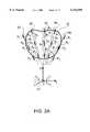
- FIG. 1is a perspective view illustrating the relationship of a probe, rectal wall and prostate during prostate examination.
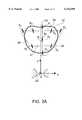
- FIG. 2Ais a schematic diagram of trajectories to be followed by a head of the probe during prostate examination while periodically pressing the probe against the prostate at the regions shown by a region of a thickened line in accordance with an embodiment of the method of the present invention.
- FIG. 2Bis a schematic diagram of trajectories to be followed by a head of the probe during prostate examination while constantly pressing the probe against the prostate with sliding at the regions shown by thickened lines.
- FIG. 3Ais a schematic diagram of an alternative trajectory to be followed by a head of the probe during prostate examination while periodically pressing the probe against the prostate at the regions shown by dark sports in accordance with an embodiment of the method of the present invention.
- FIG. 3Bis a schematic diagram of an alternative trajectory to be followed by a head of the probe during prostate examination while constantly pressing the probe against the prostate with sliding at the regions shown by thicken lines.
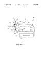
- FIG. 4Ais a cross-sectional side view of a mechanical positioning system used with the probe during prostate examination.
- FIG. 4Bis an end view of a support with a lock mechanism of the mechanical positioning system of FIG. 4A.
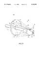
- FIG. 5is a cross-sectional side view of an alternative mechanical positioning system having ball and socket joint.
- FIG. 6shows a flow chart representative of an algorithm for determining diagnostic information from palpation data and position data to be used in mechanical imaging.
- FIG. 7is a schematic diagram of an electronic unit for providing acquisition, processing and displaying of mechanical imaging data from the probe and mechanical positioning system shown in FIG. 4A.
- FIG. 8is a perspective view of an alternative positioning system including an optical system.
- FIG. 9is a perspective view of an alternative positioning system including an electrical capacitance sensor based system.
- FIG. 10is a schematic diagram of another alternative embodiment of the positioning system including an accelerometer based positioning system and probe.
- FIG. 11is a schematic diagram of an electronic unit for providing data acquisition, processing and displaying from the positioning system shown in FIG. 10.
- FIG. 12is a cross-sectional side view of a pressure sensor assembly including a diaphragm pressure sensor assembly.
- FIG. 13is a cross-sectional side view of an alternative diaphragm pressure sensor assembly including a filled volume over the diaphragm.
- FIG. 14is a cross-sectional side view of another alternative diaphragm pressure sensor assembly including a semiconductor chip.
- FIG. 15Ais a side and cross-sectional view of the head of the probe having a biconvex shape and including a sensor assembly positioned on the head.
- FIG. 15Bis a bottom view of the head shown in FIG. 15A.
- FIG. 16Ais an elevational side view of an alternative head of the probe having a flat force sensing area and including a sensor assembly positioned on the head.
- FIG. 16Bis a bottom view of the head of the probe shown in 16A.
- the method for transrectal imaging of the prostate using the present inventionis based on the technology of medical imaging described in U.S. Pat. No. 5,524,636, which is incorporated herein by reference. This method is referred to herein as Mechanical Imaging (MI).
- MIMechanical Imaging
- the essence of MIis the reconstruction of the internal structure of soft body tissues by measuring a surface stress pattern using a pressure sensing assembly.
- the pattern of mechanical stress and its changes as a function of applied pressure and timecontain comprehensive information on the mechanical properties and geometry of the internal structures of the body tissues.
- FIG. 1schematically illustrates positioning of a transrectal probe used for measuring geometrical and mechanical parameters of the prostate during prostate examination.
- Probe 10is sized to fit within the rectum.
- Probe 10is positioned adjacent one side of rectal wall 11.
- Prostate 12is positioned adjacent the other side of rectal wall 11.
- Probe 10comprises pressure sensor assembly 13 mounted on head 14 for generating signals in response to forces imposed on pressure sensor assembly 13 as the pressure sensor assembly 13 is pressed against and moved over prostate 12.
- pressure sensor assembly 13can be formed of at least one pressure transducer.
- Shaft 15connects head 14 to handle 16.
- probe 10is inserted into the rectum and manipulated within the rectum using handle 16.
- head 14is moved within the rectum and is pressed against rectum wall 11 along predetermined trajectories to palpate prostate 12 as shown by arrow 17.
- non-manual (e.g., computer driven) operation of the probecan be used to manipulate probe 10 within the rectum.
- Measurements from pressure sensor assembly 13form pressure data 18.
- Pressure sensor assembly 13can be mounted on a variety of devices (e.g., electromechanical or piezoelectric) designed to provide automatic operation of the pressure of pressure sensor assembly 13 against the prostate 12.
- Probe 10can also include means for measuring the position and orientation of the probe, thereby determining position data 19 of the position and orientation of pressure sensor assembly 13 in coordinate system 20 referencing the human body. Thereafter, force sensor data 18 and position data 19 can be used in means for mechanical imaging of the prostate 21 to generate mechanical imaging results, as described in more detail below.
- Trajectories 23-27are sequentially followed for moving probe 10 radially from sphincter 22.
- head 14 of probe 10is moved along trajectory 23 in the direction of arrow A 1 away from sphincter 22 without pressing against prostate 12 in order to minimize displacement of the prostate.
- Second, head 14is moved along the same trajectory 23 in the direction of arrow A 2 toward sphincter 22 with periodical pressing against prostate 12 at points P 1 -P 3 positioned on trajectory 23, as shown by regions on the trajectory having a thickened line.
- a similar procedureis repeated along each trajectory 24-27 to provide pressure data 18 for mechanical imaging of prostate 12.
- FIG. 2BAn alternative type of application of pressure by pressure sensor assembly 13 along trajectories 23-27 is shown in FIG. 2B.
- Pressure sensor assembly 13is moved along trajectories 23-27 in the direction of arrow A 1 away from sphincter 22 without pressing against prostate 12.
- Pressure sensor assembly 13slides along trajectories 23-27 in the direction of arrow A 3 towards sphincter 22 while applying constant pressure by pressing against prostate 12.
- This type of palpationprovides distinct prostate geometrical features along the motion trajectory and minimizes possible prostate displacement laterally during examination.
- FIG. 3Aillustrates another pattern of trajectories for moving and pressing pressure sensor assembly 13 during prostate examination.
- pressure sensor assembly 13is moved along trajectory 33 in the direction of arrow A 1 away from sphincter 22.
- pressure sensor assembly 13is moved along trajectory 33 in the direction of arrow A 2 towards sphincter 22 with periodical pressing against prostate 12 at points P 1 -P 3 to provide prostate geometrical features along axis Y.
- pressure sensor assembly 13is moved along trajectory 34 for radially moving away from sphincter 22 without pressing against prostate 12.
- pressure sensor assembly 13is moved along trajectory 35 to laterally pass from one side of an upper region of prostate 12 to the other with pressing at points P 4 -P 7 .
- pressure sensor assembly 13is moved along trajectory 36 for radially moving toward sphincter 22 to a lower region of prostate 12 without pressing.
- pressure sensor assembly 13is moved along trajectory 37 to laterally pass from one side of the lower region of prostate 12 to the other with pressing at points P 8 -P 9 against prostate 12.
- Periodic pressing along trajectories 35 and 37provide prostate geometrical features along axis X.
- the second pattern of trajectoriesprovides an improved time duration for prostate examination, for example the examination can be performed in around 20 seconds. It will be appreciated that the pattern of trajectories and points for applying pressure against prostate 12 can be altered to provide a varied examination procedure.
- FIG. 3BAn alternative type of application of pressure by pressure sensor assembly 13 along the trajectories 33-37 is shown in FIG. 3B.
- Pressure sensor assembly 13slides along trajectories 35 and 37 in the direction of arrow A 3 while applying constant pressure against prostate 12. This type of palpation provides distinct prostate geometrical features along the motion trajectory and minimizes possible prostate displacement.
- Proplace examination device 39preferably comprises probe 10 and positioning system 40.
- Positioning system 40comprises support 41 mechanically connected to handle 16. Shaft 15 of probe 10 is received in aperture 42 of support 41. Support 41 provides a point of rest for shaft 15 against the buttocks of the patient during the prostate examination.
- Positioning system 40also includes a plurality of transducer elements 43 for generating signals in response to movements of handle 16 relative to support 41. Accordingly, transducer elements 43 generate position data 19.
- three transducer elements 43can be attached to support 41.
- Each transducer element 43can be formed of a load cell coupled to support 41 and mechanically connected to handle 16 by elastic thread 45.
- thin elastic cover 46covers head 14 and shaft 15.
- Thin elastic cover 46is held by fixing ring 47 to handle 16.
- Thin elastic cover 46can be removed from shaft 15 after use and discarded before the next use. Thereafter, a new thin elastic cover 46 can be placed over shaft 15 before the next use for providing improved hygienics of the prostate examination.
- Slot 54is formed in support 41, as shown in FIG. 4B.
- Revolving locker 55rotates around axis 56 for opening and closing slot 54.
- Revolving locker 55is shown in open position by solid line and in the closed position by dotted line. In the closed position, probe 10 is locked in a working position.
- Revolving lockerfunctions to make head 14 and shaft 15 of probe 10 available for replacing of thin elastic cover 46 before the next use of probe 10.
- FIG. 5illustrates an alternative mechanical positioning system 40 coupling support 41 to ball and socket joint 57.
- Ball and socket joint 57provides rotational motion of shaft 15.
- Positioning system 40measures rotation of shaft 15 and displacement of shaft 15 from support 41 during prostate examination.
- FIG. 6is a flow chart of the preferred method of synthesizing a three-dimensional prostate image.
- Pressure data 18 from pressure sensor assembly 13 and position data 19 from positioning system 40are acquired in real-time.
- Position data 19represents relative coordinates of some fixed point of the probe 10 represented by (x, y, z) at time t with the origin being sphincter 22.
- Analog signals representing pressure measured from all the pressure transducers of pressure sensor assembly 13 at time tform pressure data 18 represented by (p i ,t).
- pressure data 18 and position data 19are combined over time into acquired data represented by A(x,y,z,p i ,t).
- the acquired datais combined over a period of time to form pressure data file P(x,y,z) in block 61.
- a plurality of data subsets P j (x,y,z,t j )are formed in block 62 from the acquired data.
- data file P(x,y,z)is processed by one of the known volume approximation methods, as described for example by Y. L. Lute, Mathematical functions and their approximations, Academic Press Inc., New York (1975), to determine geometry of the prostate.
- corrected data P(x,y,z)is determined for correcting displacement and shifting of the prostate during examination and correcting noise of various origins. The noise originates from force and position measurement error and from artifacts related to tissue movement (movement of the prostate, movement of the patient).
- Pressure field datais calculated by processing the transformed data to minimize noise and extract the 3D spatial distribution of pressure approximating ideal conditions of measurement.
- Data related to tissue surrounding prostate 12are eliminated in block 65 from corrected pressure data file P(x,y,z). It may be done for example by removing points with negative value ⁇ P(x,y,z)/ ⁇ x at the left of the prostate center and positive value ⁇ P(x,y,z)/ ⁇ x at the right of the prostate center.
- a pattern of pressure responses of the prostate represented by P(x,y,z)is determined in block 66.
- a pattern of pressure gradient responses represented by grad ⁇ P(x,y,z) ⁇is determined from the pattern of pressure responses of the prostate. Different methods may be used to determine the pressure gradient responses grad ⁇ P(x,y,z) ⁇ , one of which is calculating partial derivatives for the pattern of pressure responses of the prostate.
- mechanical and geometrical features of the prostate inner structuresare determined from the pressure gradient responses.
- the pattern of pressure responses of the prostate P(x,y,z)is corrected subject to distortions from the stiffer tissue inside the prostate which are revealed in the pressure gradient responses to determine prostate geometrical features.
- a prostate imageis synthesized from data generated in block 68 and data generated in block 69. Having approximated (above) smooth surfaces of equal pressure, one can calculate geometrical parameters and hardness of the prostate. The surface of the examined prostate can be obtained by choosing a level of force corresponding to deformation of the rectal wall that permits the sensors to press against the prostate surface. From the pressure gradients, information on the prostate tissue hardness can be generated.
- the synthesized imagecan be displayed on a computer display.
- An average level of pressure applied to pressure sensor assembly 13, the position, real trajectory of pressure sensor assembly 13 and the predetermined pattern of trajectories for movement of the probecan be indicated in real-time in a plane projection over the prostate image on the same computer display beginning from sphincter 22. Points of pressing on the trajectories can also be displayed.
- FIG. 7illustrates a schematic diagram of a preferred embodiment of electronic unit 49 coupled to probe 10 and positioning system 40.
- a plurality of transducer elements 71form pressure sensor assembly 13 of probe 10.
- a pressure sensing circuitis formed of a plurality of amplifiers 72 to amplify respective signals generated by pressure transducer elements 71, for detecting the force imposed on each transducer element 71 of pressure sensor assembly 13.
- a plurality of amplifiers 73amplify signals generated by respective load cells 43, for detecting the position of each load cell 43 of positioning system 40.
- the amplified signals from amplifiers 72 and 73are applied to multiplexer 74.
- Control signals from button 48are also applied to multiplexer 74.
- Multiplexed signalsare converted to digital signals by analog-to-digital converter 75 and fed to processor 76.
- Processor 76is used for signal processing to calculate the position of each pressure sensing transducer 71 during prostate examination, to approximate and correct mechanical imaging of the prostate and surrounding tissues, for separation and analysis of the prostate mechanical imaging, for determining the prostate geometrical features and mechanical features of prostate inner structures such as lesions, nodules, stiffer tissue and the like, and for prostate image synthesis, as described in the method illustrated in FIG. 6.
- Display device 77is connected to processor 76, thereby displaying the prostate examination process and the results of the examination.
- Control unit 78is connected to processor 76 for controlling the prostate examination process, data analysis and data display.
- Processor 76communicates with analog-to-digital converter 75 and multiplexer 74 for sending data and control signals.
- FIG. 8illustrates an alternate embodiment of mechanical positioning system 40 as an optical positioning system 80 coupled to support 41 and handle 16 for determining real-time position data 19 of pressure sensor assembly 13 during prostate examination.
- Optical positioning system 80comprises a plurality of optical devices 81 coupled to support 41 and a plurality of optical devices 83 coupled to handle 16 for generating signals in response to movements of handle 16 relative to the support 41.
- optical positioning system 80can comprise an opto-electronic pair, in which optical device 81 can be a photodiode and optical device 83 can be a light diode. Light beams 82 are emitted from light diode 83 and are received at photodiode 81.
- Frequency modulationcan be used to provide different frequencies for each opto-electronic pair of optical devices 81 and 83.
- electronic unit 49includes a distance sensing circuit, responsive to the signals generated by optical devices 81 and 83, for detecting the position of handle 16 relative to the support 41.
- the distance sensing circuitcan be a conventional circuit for determining the distance between optical device 81 and optical device 83 from the intensity of light received at optical device 81.
- FIG. 9illustrates another alternative embodiment of mechanical positioning system 40 as an electrical capacitance positioning system 90.
- Electrical capacitance system 90is coupled to support 41 and shaft 15 for determining real-time position data 19 of pressure sensor assembly 13 during prostate examination.
- Electrical capacitance positioning system 90includes a plurality of variable-capacitance transducers for generating signals in response to movements of handle 16 relative to support 41.
- the capacitance transduceris formed of a plurality of electrodes 91 connected to support 41 and an electrode 92 connected to shaft 15.
- electronic unit 49includes a distance sensing circuit, responsive to the signals generated by electrodes 91 and electrode 92 for determining the distance between these electrodes, thereby determining the position of shaft 15 relative to support 41.
- the distance sensing circuitcan be a conventional circuit for determining the distance between electrodes 91 and electrode 92 from the amplitude of the signal generated by electrode 91 and received at electrode 92.
- FIG. 10is an alternative embodiment of mechanical positioning system 40 in which positioning system 101 and electronic unit 102 are positioned within probe 10.
- Connection 51connects electronic unit 102 to remote electronic unit 113.
- Positioning system 101determines real-time position data 19 of pressure sensor assembly 13 during prostate examination.
- positioning system 101can be located in head 14 or in handle 16 of probe 10.
- Electronic unit 102preferably can be fitted in handle 14.
- Positioning system 101can be formed of a triaxial accelerometer.
- FIG. 11shows a schematic diagram of electronic unit 102 connected to a remote electronic unit 113.
- Electronic unit 102provides data acquisition of pressure data 18 and position data 19.
- Remote unit 113provides processing and displaying of pressure data 18 and position data 19 from positioning system 101.
- Positioning system 101is formed of triaxial accelerometer 110.
- Amplifiers 111are positioned in electronic unit 102.
- Amplifiers 111amplify signals generated by accelerometers 110.
- a plurality of analog integrating circuits 112receive the amplified signals and determine relative 3D motion of probe 10 during the prostate examination. Signals from analog integrating circuits 112 and amplifiers 72, and button 48 are applied to multiplexer 74.
- Remote electronic circuit 113also includes processor 76, display device 77 and control unit 78.
- Processor 76communicates with analog-to-digital converter 75 and multiplexer 74 for sending data and control signals.
- a storage device 114can be used in remote electronic unit 113 for storing the results of the prostate examination generated by processor 76.
- FIG. 12is a cross sectional diagram of an embodiment of pressure sensor assembly 13.
- a plurality of flexing diaphragms 122are located on bearing 120.
- Bearing 120can be positioned at the base of head 14 or can be positioned at any surface of head 14.
- Bottom side 123 of flexing diaphragms 122is bonded to a fully active or half active Wheatstone Bridge 126 having strain gages 121.
- Wheatstone Bridge 126can include semiconductor strain gages, diffused piezoresistive strain sensors, ion-implanted piezoresistive strain sensors, thin film piezoresistive strain sensors or epitaxial piezoresistive strain sensors or other conventional sensors.
- Wires 127 coupled to strain gages 121are connected with electrical connector 124 to electrical wires 125. Electrical wires 125 can be connected to connection 52.
- FIG. 13shows an alternative embodiment of pressure sensor assembly 13 in which flexing diaphragms 122 are positioned in respective cylinders 132. Each cylinder 132 is filled with an elastic material 131.
- FIG. 14illustrates an alternative embodiment of pressure sensor assembly 13 formed of plurality of microfabricated pressure sensors 141 integrated into a monolithic sensor-circuit chip 148. Sensing surface 145 of pressure sensors 141 is covered with an elastic protective film 142. Monolithic sensor-circuit chip 148 is formed of semiconductor layer 147, oxide coating 144 and electrical connectors 143. Electrical connectors 143 can be connected to connection 52.
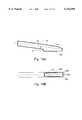
- FIGS. 15A and 15Billustrate an embodiment of head 14 of probe 10.
- Head 14is formed of surface 151.
- surface 151has a biconvex shape.
- a plurality of pressure sensors 152are positioned along lines 153.
- Pressure sensors 152provide palpation data 18.
- surface 151can have a spherical shape or alternative geometric shapes which are sized to fit in the rectum.
- FIGS. 16A and 16Billustrate an alternative embodiment of head 14 of probe 10.
- Head 14is formed of surface 161.
- surface 161is substantially flat.
- Surface 161is formed at an angle ⁇ from the axis, A p , of probe 10.
- angle ⁇can be about 6°.
- a plurality of pressure sensors 163are positioned along lines 164. Pressure sensors 163 provide palpation data 18.
- surface 161is concave or convex.
Landscapes
- Health & Medical Sciences (AREA)
- Life Sciences & Earth Sciences (AREA)
- Engineering & Computer Science (AREA)
- Physics & Mathematics (AREA)
- Surgery (AREA)
- General Health & Medical Sciences (AREA)
- Veterinary Medicine (AREA)
- Public Health (AREA)
- Biophysics (AREA)
- Pathology (AREA)
- Biomedical Technology (AREA)
- Heart & Thoracic Surgery (AREA)
- Medical Informatics (AREA)
- Molecular Biology (AREA)
- Animal Behavior & Ethology (AREA)
- Nuclear Medicine, Radiotherapy & Molecular Imaging (AREA)
- Radiology & Medical Imaging (AREA)
- Oral & Maxillofacial Surgery (AREA)
- Dentistry (AREA)
- Gynecology & Obstetrics (AREA)
- Human Computer Interaction (AREA)
- Hematology (AREA)
- Remote Sensing (AREA)
- General Physics & Mathematics (AREA)
- Reproductive Health (AREA)
- Radar, Positioning & Navigation (AREA)
- Computer Networks & Wireless Communication (AREA)
- Optics & Photonics (AREA)
- Physiology (AREA)
- Measuring And Recording Apparatus For Diagnosis (AREA)
- Ultra Sonic Daignosis Equipment (AREA)
- Force Measurement Appropriate To Specific Purposes (AREA)
Abstract
Description
Claims (32)
Priority Applications (5)
| Application Number | Priority Date | Filing Date | Title |
|---|---|---|---|
| US09/359,200US6142959A (en) | 1992-12-21 | 1999-07-22 | Device for palpation and mechanical imaging of the prostate |
| PCT/US2000/019756WO2001006927A1 (en) | 1999-07-22 | 2000-07-21 | Device for palpation and mechanical imaging of the prostate |
| AU61146/00AAU6114600A (en) | 1999-07-22 | 2000-07-21 | Device for palpation and mechanical imaging of the prostate |
| EP00947563AEP1418843A4 (en) | 1999-07-22 | 2000-07-21 | Device for palpation and mechanical imaging of the prostate |
| JP2001511823AJP2003505134A (en) | 1999-07-22 | 2000-07-21 | Apparatus for palpation and mechanical imaging of the prostate |
Applications Claiming Priority (4)
| Application Number | Priority Date | Filing Date | Title |
|---|---|---|---|
| US07/994,109US5524636A (en) | 1992-12-21 | 1992-12-21 | Method and apparatus for elasticity imaging |
| US08/607,645US5785663A (en) | 1992-12-21 | 1996-02-27 | Method and device for mechanical imaging of prostate |
| US08/872,559US5922018A (en) | 1992-12-21 | 1997-06-10 | Method for using a transrectal probe to mechanically image the prostate gland |
| US09/359,200US6142959A (en) | 1992-12-21 | 1999-07-22 | Device for palpation and mechanical imaging of the prostate |
Related Parent Applications (1)
| Application Number | Title | Priority Date | Filing Date |
|---|---|---|---|
| US08/872,559Continuation-In-PartUS5922018A (en) | 1992-12-21 | 1997-06-10 | Method for using a transrectal probe to mechanically image the prostate gland |
Publications (1)
| Publication Number | Publication Date |
|---|---|
| US6142959Atrue US6142959A (en) | 2000-11-07 |
Family
ID=23412760
Family Applications (1)
| Application Number | Title | Priority Date | Filing Date |
|---|---|---|---|
| US09/359,200Expired - Fee RelatedUS6142959A (en) | 1992-12-21 | 1999-07-22 | Device for palpation and mechanical imaging of the prostate |
Country Status (5)
| Country | Link |
|---|---|
| US (1) | US6142959A (en) |
| EP (1) | EP1418843A4 (en) |
| JP (1) | JP2003505134A (en) |
| AU (1) | AU6114600A (en) |
| WO (1) | WO2001006927A1 (en) |
Cited By (42)
| Publication number | Priority date | Publication date | Assignee | Title |
|---|---|---|---|---|
| US20020077568A1 (en)* | 2000-11-22 | 2002-06-20 | Haddock Thomas F. | Biological vessel volume measurement method and apparatus utilizing micro accelerometer |
| US20020095083A1 (en)* | 1997-03-11 | 2002-07-18 | Philippe Cinquin | Process and device for the preoperative determination of the positioning data of endoprosthetic parts |
| US6569108B2 (en) | 2001-03-28 | 2003-05-27 | Profile, Llc | Real time mechanical imaging of the prostate |
| US20040231772A1 (en)* | 2002-11-12 | 2004-11-25 | Leonard Todd E. | Intelligent medical device barrier |
| WO2005051191A1 (en)* | 2003-11-24 | 2005-06-09 | Sensors For Medicine, Inc. | Apparatus and method for measuring the dimensions of the palpable surface of the prostate |
| US20050154256A1 (en)* | 2004-01-14 | 2005-07-14 | Precision Optics Corporation | Convergence optics for stereoscopic imaging systems |
| US20060064038A1 (en)* | 2003-02-12 | 2006-03-23 | Nihon University | Device for measuring elastic characteristics of organism tissue |
| US20060224037A1 (en)* | 2005-04-04 | 2006-10-05 | Isaac Ostrovsky | Device and method for positioning of a therapeutic device |
| US20070106328A1 (en)* | 2002-09-26 | 2007-05-10 | Wardle John L | Retrieval devices for anchored cardiovascular sensors |
| US20070129635A1 (en)* | 1997-09-09 | 2007-06-07 | Redano Richard T | Apparatus for measuring hemodynamic parameters |
| US20070214872A1 (en)* | 2006-02-14 | 2007-09-20 | Mettler-Toledo Ag | Measuring device, measuring probe, and method of operating the measuring device |
| US20070293792A1 (en)* | 2006-06-15 | 2007-12-20 | Sliwa John W | Prostate BPH and tumor detector also useable on other tissues |
| US20080221484A1 (en)* | 2005-05-06 | 2008-09-11 | Sarvazyan Armen P | Method and a dual-array transducer probe for real time mechanical imaging of prostate |
| US20090005707A1 (en)* | 2005-05-06 | 2009-01-01 | Sarvazyan Armen P | Method and device for real time mechanical imaging of prostate |
| WO2009067573A3 (en)* | 2007-11-20 | 2009-09-03 | Sensors For Medicine, Inc. | Apparatus and method for measuring the dimensions of the palpable surface of the prostate |
| US20110054357A1 (en)* | 2009-09-02 | 2011-03-03 | Artann Laboratories, Inc. | Methods for characterizing vaginal tissue elasticity |
| US20110196263A1 (en)* | 2009-09-02 | 2011-08-11 | Artann Laboratories, Inc. | Methods for assessment of pelvic organ conditions affecting the vagina |
| US8303511B2 (en) | 2002-09-26 | 2012-11-06 | Pacesetter, Inc. | Implantable pressure transducer system optimized for reduced thrombosis effect |
| US20140018820A1 (en)* | 2012-07-11 | 2014-01-16 | Samsung Electronics Co., Ltd. | Palpation apparatus and method using robot |
| US8694079B1 (en) | 2012-10-30 | 2014-04-08 | Medicametrix, Inc. | Double membrane prostate glove |
| US8838214B2 (en) | 2012-10-30 | 2014-09-16 | Medicametrix, Inc. | Finger clip for prostate glove |
| US9402564B2 (en) | 2012-10-30 | 2016-08-02 | Medicametrix, Inc. | Prostate glove with measurement grid |
| US9402547B2 (en) | 2012-10-30 | 2016-08-02 | Medicametrix, Inc. | Prostate glove with receiver fibers |
| CN106264436A (en)* | 2015-05-22 | 2017-01-04 | 北京先通康桥医药科技有限公司 | A kind of palaption probe |
| US9538952B2 (en) | 2012-10-30 | 2017-01-10 | Medicametrix, Inc. | Controller for measuring prostate volume |
| US20170042626A1 (en)* | 2015-07-31 | 2017-02-16 | Advanced Tactile Imaging, Inc. | Method and probe for providing tactile feedback in laparoscopic surgery |
| US9726647B2 (en) | 2015-03-17 | 2017-08-08 | Hemosonics, Llc | Determining mechanical properties via ultrasound-induced resonance |
| US10004450B2 (en) | 2016-05-03 | 2018-06-26 | Texas Medical Center | Tactile sensing device for lumbar punctures |
| DE102017102646A1 (en) | 2017-02-10 | 2018-08-16 | Stephan Swart | Instrument for finding trigger points |
| US10383610B2 (en) | 2017-10-27 | 2019-08-20 | Intuitap Medical, Inc. | Tactile sensing and needle guidance device |
| US10413231B2 (en) | 2009-07-23 | 2019-09-17 | Nicholas Ahn | Orifice probe apparatus and a method of use thereof |
| US10670479B2 (en) | 2018-02-27 | 2020-06-02 | Methode Electronics, Inc. | Towing systems and methods using magnetic field sensing |
| US10696109B2 (en) | 2017-03-22 | 2020-06-30 | Methode Electronics Malta Ltd. | Magnetolastic based sensor assembly |
| US10962524B2 (en) | 2011-02-15 | 2021-03-30 | HomoSonics LLC | Characterization of blood hemostasis and oxygen transport parameters |
| US11014417B2 (en) | 2018-02-27 | 2021-05-25 | Methode Electronics, Inc. | Towing systems and methods using magnetic field sensing |
| US11084342B2 (en) | 2018-02-27 | 2021-08-10 | Methode Electronics, Inc. | Towing systems and methods using magnetic field sensing |
| IT202000002914A1 (en)* | 2020-02-13 | 2021-08-13 | Vi Biotech Soc A Responsabilita Limitata Semplificata | Device for detecting the characteristics of the prostate. |
| US11135882B2 (en) | 2018-02-27 | 2021-10-05 | Methode Electronics, Inc. | Towing systems and methods using magnetic field sensing |
| US11221262B2 (en) | 2018-02-27 | 2022-01-11 | Methode Electronics, Inc. | Towing systems and methods using magnetic field sensing |
| ES2921203A1 (en)* | 2021-02-15 | 2022-08-19 | Fundacion Para La Investigacion Del Hospital Univ Y Politecnico La Fe De La Comunidad Valenciana | Prostate palpation device (Machine-translation by Google Translate, not legally binding) |
| US11491832B2 (en) | 2018-02-27 | 2022-11-08 | Methode Electronics, Inc. | Towing systems and methods using magnetic field sensing |
| US11638552B2 (en) | 2015-12-22 | 2023-05-02 | Medicametrix, Inc. | Prostate glove, fingertip optical encoder, connector system, and related methods |
Families Citing this family (4)
| Publication number | Priority date | Publication date | Assignee | Title |
|---|---|---|---|---|
| US7166075B2 (en)* | 2002-03-08 | 2007-01-23 | Wisconsin Alumni Research Foundation | Elastographic imaging of in vivo soft tissue |
| GB0228276D0 (en)* | 2002-12-04 | 2003-01-08 | Univ Heriot Watt | Apparatus for mapping biological tissue quality |
| US7297116B2 (en) | 2003-04-21 | 2007-11-20 | Wisconsin Alumni Research Foundation | Method and apparatus for imaging the cervix and uterine wall |
| RU2567819C2 (en)* | 2013-12-09 | 2015-11-10 | Сергей Александрович Акопян | Indicator of condition and change of elastic properties of soft tissues |
Citations (19)
| Publication number | Priority date | Publication date | Assignee | Title |
|---|---|---|---|---|
| US4250894A (en)* | 1978-11-14 | 1981-02-17 | Yeda Research & Development Co., Ltd. | Instrument for viscoelastic measurement |
| US4711248A (en)* | 1983-12-01 | 1987-12-08 | Biokinetics, Inc. | Physiological pressure monitor |
| US4722348A (en)* | 1985-09-17 | 1988-02-02 | Sentron V.O.F. | Catheter tip pressure transducer |
| US4809710A (en)* | 1988-01-11 | 1989-03-07 | Williamson Jeffrey L | Multilumen manometer catheter |
| US4869265A (en)* | 1987-04-03 | 1989-09-26 | Western Clinical Engineering Ltd. | Biomedical pressure transducer |
| US4893634A (en)* | 1987-06-01 | 1990-01-16 | Problamnaya Nauchno-Issledovatelskaya Laboratoria Vspomogatelnogo Krovoobraschenia | Device for cleansing measuring pressure in the colon |
| US4947851A (en)* | 1988-02-19 | 1990-08-14 | Institute for Physical Chemistry | Method and device for acoustic testing of elasticity of biological tissues |
| US5067491A (en)* | 1989-12-08 | 1991-11-26 | Becton, Dickinson And Company | Barrier coating on blood contacting devices |
| US5107837A (en)* | 1989-11-17 | 1992-04-28 | Board Of Regents, University Of Texas | Method and apparatus for measurement and imaging of tissue compressibility or compliance |
| US5170790A (en)* | 1990-04-06 | 1992-12-15 | Technomed International | Arm having an end movable in translation, and therapeutic treatment apparatus constituting an application thereof |
| US5178148A (en)* | 1990-04-06 | 1993-01-12 | Technomed International | Method of automatically measuring the volume of a tumor or of a gland, in particular the prostate, a measuring device, and a method and apparatus constituting and application thereof |
| US5265612A (en)* | 1992-12-21 | 1993-11-30 | Medical Biophysics International | Intracavity ultrasonic device for elasticity imaging |
| US5293870A (en)* | 1989-11-17 | 1994-03-15 | Board Of Regents The University Of Texas System | Method and apparatus for elastographic measurement and imaging |
| US5423332A (en)* | 1993-07-22 | 1995-06-13 | Uromed Corporation | Device and method for determining the mass or volume of a body part |
| US5474070A (en)* | 1989-11-17 | 1995-12-12 | The Board Of Regents Of The University Of Texas System | Method and apparatus for elastographic measurement and imaging |
| US5522399A (en)* | 1994-09-26 | 1996-06-04 | Wilk; Peter J. | Catheterization device and associated assembly |
| US5526829A (en)* | 1993-03-18 | 1996-06-18 | Smith; Margaret A. | Hair curling system |
| US5836894A (en)* | 1992-12-21 | 1998-11-17 | Artann Laboratories | Apparatus for measuring mechanical parameters of the prostate and for imaging the prostate using such parameters |
| US5922018A (en)* | 1992-12-21 | 1999-07-13 | Artann Corporation | Method for using a transrectal probe to mechanically image the prostate gland |
Family Cites Families (8)
| Publication number | Priority date | Publication date | Assignee | Title |
|---|---|---|---|---|
| JPS61122618A (en)* | 1984-11-20 | 1986-06-10 | Olympus Optical Co Ltd | Endoscope device |
| JP2718524B2 (en)* | 1988-10-31 | 1998-02-25 | オリンパス光学工業株式会社 | Rectal insertion type prostate hyperthermia applicator |
| JP2505572Y2 (en)* | 1989-07-03 | 1996-07-31 | 株式会社東海理化電機製作所 | Pressure sensor |
| US5785663A (en)* | 1992-12-21 | 1998-07-28 | Artann Corporation | Method and device for mechanical imaging of prostate |
| US5524636A (en)* | 1992-12-21 | 1996-06-11 | Artann Corporation Dba Artann Laboratories | Method and apparatus for elasticity imaging |
| US5335669A (en)* | 1993-04-21 | 1994-08-09 | American Medical Systems, Inc. | Rectal probe with temperature sensor |
| JPH08322809A (en)* | 1995-05-29 | 1996-12-10 | Olympus Optical Co Ltd | Taction sensor |
| DE19627741A1 (en)* | 1996-07-10 | 1998-01-15 | Mannesmann Vdo Ag | Pressure maintenance device |
- 1999
- 1999-07-22USUS09/359,200patent/US6142959A/ennot_activeExpired - Fee Related
- 2000
- 2000-07-21WOPCT/US2000/019756patent/WO2001006927A1/enactiveApplication Filing
- 2000-07-21EPEP00947563Apatent/EP1418843A4/ennot_activeWithdrawn
- 2000-07-21AUAU61146/00Apatent/AU6114600A/ennot_activeAbandoned
- 2000-07-21JPJP2001511823Apatent/JP2003505134A/enactivePending
Patent Citations (19)
| Publication number | Priority date | Publication date | Assignee | Title |
|---|---|---|---|---|
| US4250894A (en)* | 1978-11-14 | 1981-02-17 | Yeda Research & Development Co., Ltd. | Instrument for viscoelastic measurement |
| US4711248A (en)* | 1983-12-01 | 1987-12-08 | Biokinetics, Inc. | Physiological pressure monitor |
| US4722348A (en)* | 1985-09-17 | 1988-02-02 | Sentron V.O.F. | Catheter tip pressure transducer |
| US4869265A (en)* | 1987-04-03 | 1989-09-26 | Western Clinical Engineering Ltd. | Biomedical pressure transducer |
| US4893634A (en)* | 1987-06-01 | 1990-01-16 | Problamnaya Nauchno-Issledovatelskaya Laboratoria Vspomogatelnogo Krovoobraschenia | Device for cleansing measuring pressure in the colon |
| US4809710A (en)* | 1988-01-11 | 1989-03-07 | Williamson Jeffrey L | Multilumen manometer catheter |
| US4947851A (en)* | 1988-02-19 | 1990-08-14 | Institute for Physical Chemistry | Method and device for acoustic testing of elasticity of biological tissues |
| US5107837A (en)* | 1989-11-17 | 1992-04-28 | Board Of Regents, University Of Texas | Method and apparatus for measurement and imaging of tissue compressibility or compliance |
| US5293870A (en)* | 1989-11-17 | 1994-03-15 | Board Of Regents The University Of Texas System | Method and apparatus for elastographic measurement and imaging |
| US5474070A (en)* | 1989-11-17 | 1995-12-12 | The Board Of Regents Of The University Of Texas System | Method and apparatus for elastographic measurement and imaging |
| US5067491A (en)* | 1989-12-08 | 1991-11-26 | Becton, Dickinson And Company | Barrier coating on blood contacting devices |
| US5170790A (en)* | 1990-04-06 | 1992-12-15 | Technomed International | Arm having an end movable in translation, and therapeutic treatment apparatus constituting an application thereof |
| US5178148A (en)* | 1990-04-06 | 1993-01-12 | Technomed International | Method of automatically measuring the volume of a tumor or of a gland, in particular the prostate, a measuring device, and a method and apparatus constituting and application thereof |
| US5265612A (en)* | 1992-12-21 | 1993-11-30 | Medical Biophysics International | Intracavity ultrasonic device for elasticity imaging |
| US5836894A (en)* | 1992-12-21 | 1998-11-17 | Artann Laboratories | Apparatus for measuring mechanical parameters of the prostate and for imaging the prostate using such parameters |
| US5922018A (en)* | 1992-12-21 | 1999-07-13 | Artann Corporation | Method for using a transrectal probe to mechanically image the prostate gland |
| US5526829A (en)* | 1993-03-18 | 1996-06-18 | Smith; Margaret A. | Hair curling system |
| US5423332A (en)* | 1993-07-22 | 1995-06-13 | Uromed Corporation | Device and method for determining the mass or volume of a body part |
| US5522399A (en)* | 1994-09-26 | 1996-06-04 | Wilk; Peter J. | Catheterization device and associated assembly |
Non-Patent Citations (2)
| Title |
|---|
| D. J. Rubens, MD et al., "Sonoelasticity Imaging of Prostate Cancer: In Vitro Results", Journal of Radiology, 195, No. 2. |
| D. J. Rubens, MD et al., Sonoelasticity Imaging of Prostate Cancer: In Vitro Results , Journal of Radiology, 195, No. 2.* |
Cited By (70)
| Publication number | Priority date | Publication date | Assignee | Title |
|---|---|---|---|---|
| US6915150B2 (en) | 1997-03-11 | 2005-07-05 | Aesculap Ag & Co. Kg | Process and device for the preoperative determination of the positioning data of endoprosthetic parts |
| US20040181144A1 (en)* | 1997-03-11 | 2004-09-16 | Aesculap Ag & Co. Kg | Process and device for the preoperative determination of the positioning data of endoprosthetic parts |
| US7033360B2 (en) | 1997-03-11 | 2006-04-25 | Aesculap Ag & Co. Kg | Process and device for the preoperative determination of the positioning data endoprosthetic parts |
| US20020095083A1 (en)* | 1997-03-11 | 2002-07-18 | Philippe Cinquin | Process and device for the preoperative determination of the positioning data of endoprosthetic parts |
| US20070129635A1 (en)* | 1997-09-09 | 2007-06-07 | Redano Richard T | Apparatus for measuring hemodynamic parameters |
| US20020077568A1 (en)* | 2000-11-22 | 2002-06-20 | Haddock Thomas F. | Biological vessel volume measurement method and apparatus utilizing micro accelerometer |
| US6569108B2 (en) | 2001-03-28 | 2003-05-27 | Profile, Llc | Real time mechanical imaging of the prostate |
| EP2316335A1 (en)* | 2001-03-28 | 2011-05-04 | ProUroCare Medical Inc. | Real-time mechanical imaging of the prostate |
| US7890186B2 (en) | 2002-09-26 | 2011-02-15 | Pacesetter, Inc. | Retrieval devices for anchored cardiovascular sensors |
| US9060696B2 (en)* | 2002-09-26 | 2015-06-23 | Pacesetter, Inc. | Implantable pressure transducer system optimized to correct environmental factors |
| US20070106328A1 (en)* | 2002-09-26 | 2007-05-10 | Wardle John L | Retrieval devices for anchored cardiovascular sensors |
| US8303511B2 (en) | 2002-09-26 | 2012-11-06 | Pacesetter, Inc. | Implantable pressure transducer system optimized for reduced thrombosis effect |
| US20040231772A1 (en)* | 2002-11-12 | 2004-11-25 | Leonard Todd E. | Intelligent medical device barrier |
| US7615014B2 (en)* | 2003-02-12 | 2009-11-10 | Nihon University | Device for measuring elastic properties of tissue |
| US20060064038A1 (en)* | 2003-02-12 | 2006-03-23 | Nihon University | Device for measuring elastic characteristics of organism tissue |
| US20060122538A1 (en)* | 2003-11-24 | 2006-06-08 | Kellett Ian P | Apparatus and method for measuring the dimensions of the palpable surface of the prostate |
| US7309319B2 (en) | 2003-11-24 | 2007-12-18 | Sensors For Medicine, Inc. | Apparatus and method for measuring the dimensions of the palpable surface of the prostate |
| WO2005051191A1 (en)* | 2003-11-24 | 2005-06-09 | Sensors For Medicine, Inc. | Apparatus and method for measuring the dimensions of the palpable surface of the prostate |
| US20050154256A1 (en)* | 2004-01-14 | 2005-07-14 | Precision Optics Corporation | Convergence optics for stereoscopic imaging systems |
| US20060224037A1 (en)* | 2005-04-04 | 2006-10-05 | Isaac Ostrovsky | Device and method for positioning of a therapeutic device |
| US7837682B2 (en)* | 2005-04-04 | 2010-11-23 | Boston Scientific Scimed, Inc. | Device and method for positioning of a therapeutic device |
| US7819824B2 (en)* | 2005-05-06 | 2010-10-26 | Artann Laboratories Inc. | Method and a dual-array transducer probe for real time mechanical imaging of prostate |
| US20120277632A1 (en)* | 2005-05-06 | 2012-11-01 | Artann Laboratories, Inc. | Method and a dual-array transducer probe for real time mechanical imaging of prostate |
| US7922674B2 (en)* | 2005-05-06 | 2011-04-12 | Artann Laboratories Inc | Method and device for real time mechanical imaging of prostate |
| US20090005707A1 (en)* | 2005-05-06 | 2009-01-01 | Sarvazyan Armen P | Method and device for real time mechanical imaging of prostate |
| US20080221484A1 (en)* | 2005-05-06 | 2008-09-11 | Sarvazyan Armen P | Method and a dual-array transducer probe for real time mechanical imaging of prostate |
| US7924017B2 (en)* | 2006-02-14 | 2011-04-12 | Mettler-Toledo Ag | Measuring device, measuring probe, and method of operating the measuring device |
| US20070214872A1 (en)* | 2006-02-14 | 2007-09-20 | Mettler-Toledo Ag | Measuring device, measuring probe, and method of operating the measuring device |
| US20070293792A1 (en)* | 2006-06-15 | 2007-12-20 | Sliwa John W | Prostate BPH and tumor detector also useable on other tissues |
| WO2009067573A3 (en)* | 2007-11-20 | 2009-09-03 | Sensors For Medicine, Inc. | Apparatus and method for measuring the dimensions of the palpable surface of the prostate |
| US10413231B2 (en) | 2009-07-23 | 2019-09-17 | Nicholas Ahn | Orifice probe apparatus and a method of use thereof |
| US8419659B2 (en)* | 2009-09-02 | 2013-04-16 | Artann Laboratories | Methods for assessment of improvements in pelvic organ conditions after an interventional procedure |
| US20110054357A1 (en)* | 2009-09-02 | 2011-03-03 | Artann Laboratories, Inc. | Methods for characterizing vaginal tissue elasticity |
| US8187208B2 (en) | 2009-09-02 | 2012-05-29 | Artann Laboratories Inc. | Methods for assessment of pelvic organ conditions affecting the vagina |
| US8052622B2 (en) | 2009-09-02 | 2011-11-08 | Artann Laboratories Inc | Methods for characterizing vaginal tissue elasticity |
| US20110196263A1 (en)* | 2009-09-02 | 2011-08-11 | Artann Laboratories, Inc. | Methods for assessment of pelvic organ conditions affecting the vagina |
| US20120259247A1 (en)* | 2009-09-02 | 2012-10-11 | Artann Laboratories, Inc. | Methods for assessment of improvements in pelvic organ conditions after an interventional procedure |
| US10962524B2 (en) | 2011-02-15 | 2021-03-30 | HomoSonics LLC | Characterization of blood hemostasis and oxygen transport parameters |
| US11680940B2 (en) | 2011-02-15 | 2023-06-20 | Hemosonics Llc | Characterization of blood hemostasis and oxygen transport parameters |
| US20140018820A1 (en)* | 2012-07-11 | 2014-01-16 | Samsung Electronics Co., Ltd. | Palpation apparatus and method using robot |
| US9538952B2 (en) | 2012-10-30 | 2017-01-10 | Medicametrix, Inc. | Controller for measuring prostate volume |
| US9402547B2 (en) | 2012-10-30 | 2016-08-02 | Medicametrix, Inc. | Prostate glove with receiver fibers |
| US8694079B1 (en) | 2012-10-30 | 2014-04-08 | Medicametrix, Inc. | Double membrane prostate glove |
| US8838214B2 (en) | 2012-10-30 | 2014-09-16 | Medicametrix, Inc. | Finger clip for prostate glove |
| US9402564B2 (en) | 2012-10-30 | 2016-08-02 | Medicametrix, Inc. | Prostate glove with measurement grid |
| US9726647B2 (en) | 2015-03-17 | 2017-08-08 | Hemosonics, Llc | Determining mechanical properties via ultrasound-induced resonance |
| US10495613B2 (en) | 2015-03-17 | 2019-12-03 | Hemosonics, Llc | Determining mechanical properties via ultrasound-induced resonance |
| US11656206B2 (en) | 2015-03-17 | 2023-05-23 | Hemosonics Llc | Determining mechanical properties via ultrasound-induced resonance |
| US12163925B2 (en) | 2015-03-17 | 2024-12-10 | Hemosonics Llc | Determining mechanical properties via ultrasound-induced resonance |
| US11002712B2 (en) | 2015-03-17 | 2021-05-11 | Hemosonics Llc | Determining mechanical properties via ultrasound-induced resonance |
| CN106264436A (en)* | 2015-05-22 | 2017-01-04 | 北京先通康桥医药科技有限公司 | A kind of palaption probe |
| US20170042626A1 (en)* | 2015-07-31 | 2017-02-16 | Advanced Tactile Imaging, Inc. | Method and probe for providing tactile feedback in laparoscopic surgery |
| US11638552B2 (en) | 2015-12-22 | 2023-05-02 | Medicametrix, Inc. | Prostate glove, fingertip optical encoder, connector system, and related methods |
| US11179097B2 (en) | 2016-05-03 | 2021-11-23 | Texas Medical Center | Tactile sensing device for lumbar punctures |
| US10004450B2 (en) | 2016-05-03 | 2018-06-26 | Texas Medical Center | Tactile sensing device for lumbar punctures |
| DE102017102646A1 (en) | 2017-02-10 | 2018-08-16 | Stephan Swart | Instrument for finding trigger points |
| DE102017102646B4 (en)* | 2017-02-10 | 2020-12-10 | Stephan Swart | Instrument for finding trigger points |
| US10940726B2 (en) | 2017-03-22 | 2021-03-09 | Methode Electronics Malta Ltd. | Magnetoelastic based sensor assembly |
| US10696109B2 (en) | 2017-03-22 | 2020-06-30 | Methode Electronics Malta Ltd. | Magnetolastic based sensor assembly |
| US11000311B2 (en) | 2017-10-27 | 2021-05-11 | Intuitap Medical, Inc. | Tactile sensing and needle guidance device |
| US10383610B2 (en) | 2017-10-27 | 2019-08-20 | Intuitap Medical, Inc. | Tactile sensing and needle guidance device |
| US10670479B2 (en) | 2018-02-27 | 2020-06-02 | Methode Electronics, Inc. | Towing systems and methods using magnetic field sensing |
| US11135882B2 (en) | 2018-02-27 | 2021-10-05 | Methode Electronics, Inc. | Towing systems and methods using magnetic field sensing |
| US11221262B2 (en) | 2018-02-27 | 2022-01-11 | Methode Electronics, Inc. | Towing systems and methods using magnetic field sensing |
| US11491832B2 (en) | 2018-02-27 | 2022-11-08 | Methode Electronics, Inc. | Towing systems and methods using magnetic field sensing |
| US11084342B2 (en) | 2018-02-27 | 2021-08-10 | Methode Electronics, Inc. | Towing systems and methods using magnetic field sensing |
| US11014417B2 (en) | 2018-02-27 | 2021-05-25 | Methode Electronics, Inc. | Towing systems and methods using magnetic field sensing |
| WO2021161233A1 (en)* | 2020-02-13 | 2021-08-19 | Vi Biotech Societa' A Responsabilita' Limitata Semplificata | Device for detecting prostate features |
| IT202000002914A1 (en)* | 2020-02-13 | 2021-08-13 | Vi Biotech Soc A Responsabilita Limitata Semplificata | Device for detecting the characteristics of the prostate. |
| ES2921203A1 (en)* | 2021-02-15 | 2022-08-19 | Fundacion Para La Investigacion Del Hospital Univ Y Politecnico La Fe De La Comunidad Valenciana | Prostate palpation device (Machine-translation by Google Translate, not legally binding) |
Also Published As
| Publication number | Publication date |
|---|---|
| AU6114600A (en) | 2001-02-13 |
| JP2003505134A (en) | 2003-02-12 |
| WO2001006927A1 (en) | 2001-02-01 |
| EP1418843A1 (en) | 2004-05-19 |
| EP1418843A4 (en) | 2010-01-06 |
Similar Documents
| Publication | Publication Date | Title |
|---|---|---|
| US6142959A (en) | Device for palpation and mechanical imaging of the prostate | |
| US6569108B2 (en) | Real time mechanical imaging of the prostate | |
| EP0955890B1 (en) | Device for imaging the prostata | |
| US6595933B2 (en) | Self-palpation device for examination of breast with 3-D positioning system | |
| US6620115B2 (en) | Apparatus and method for mechanical imaging of breast | |
| US5922018A (en) | Method for using a transrectal probe to mechanically image the prostate gland | |
| US5836894A (en) | Apparatus for measuring mechanical parameters of the prostate and for imaging the prostate using such parameters | |
| JP4997225B2 (en) | Dual array transducer probe for real-time mechanical imaging of the prostate | |
| US6165128A (en) | Method and apparatus for making an image of a lumen or other body cavity and its surrounding tissue | |
| US9826959B2 (en) | Ultrasonic diagnostic device | |
| Lorenz et al. | A new system for the acquisition of ultrasonic multicompression strain images of the human prostate in vivo | |
| US5265612A (en) | Intracavity ultrasonic device for elasticity imaging | |
| US20070038152A1 (en) | Tactile breast imager and method for use | |
| US5423332A (en) | Device and method for determining the mass or volume of a body part | |
| US20110130685A1 (en) | Method and device for real time mechanical imaging of prostate | |
| Lee et al. | EUS elastography: advances in diagnostic EUS of the pancreas | |
| WO2008029728A1 (en) | Ultrasonograph | |
| Panteliou et al. | Development of a new optical device and its feasibility in prostate cancer detection |
Legal Events
| Date | Code | Title | Description |
|---|---|---|---|
| AS | Assignment | Owner name:ARTANN LABORATORIES, NEW JERSEY Free format text:ASSIGNMENT OF ASSIGNORS INTEREST;ASSIGNORS:SARVAZYAN, ARMEN P.;EGOROV, VLADIMIR;REEL/FRAME:010354/0728 Effective date:19990721 | |
| AS | Assignment | Owner name:ARMED L.L.C., MINNESOTA Free format text:ASSIGNMENT OF ASSIGNORS INTEREST;ASSIGNOR:ARTANN LABORATORIES;REEL/FRAME:011047/0499 Effective date:20000629 | |
| AS | Assignment | Owner name:PROFILE, LLC, DELAWARE Free format text:ASSIGNMENT OF ASSIGNORS INTEREST;ASSIGNOR:ARMED, INC.;REEL/FRAME:012177/0344 Effective date:20010829 | |
| FPAY | Fee payment | Year of fee payment:4 | |
| SULP | Surcharge for late payment | ||
| REMI | Maintenance fee reminder mailed | ||
| AS | Assignment | Owner name:PROUROCARE MEDICAL, INC., MINNESOTA Free format text:ASSET PURCHASE AGREEMENT;ASSIGNOR:PROFILE L.L.C.;REEL/FRAME:021194/0748 Effective date:20080403 | |
| AS | Assignment | Owner name:PROUROCARE MEDICAL INC., MINNESOTA Free format text:CORRECTIVE ASSIGNMENT TO CORRECT THE THE WRONG SPELLING OF PROUROCARE MEDICAL, IMC. PREVIOUSLY RECORDED ON REEL 021194 FRAME 0748. ASSIGNOR(S) HEREBY CONFIRMS THE ASSIGNMENT OF ASSIGNOR'S INTEREST.;ASSIGNOR:PROFILE L.L.C.;REEL/FRAME:021230/0051 Effective date:20080403 | |
| AS | Assignment | Owner name:ARMED, L.L.C. (A DELAWARE LIMITED LIABILITY COMPAN Free format text:MERGER;ASSIGNOR:ARMED, L.L.C. (AN ALABAMA LIMITED LIABILITY COMPANY);REEL/FRAME:021428/0331 Effective date:19980505 Owner name:ARMED, INC., MINNESOTA Free format text:MERGER;ASSIGNOR:ARMED, L.L.C. (A DELAWARE LIMITED LIABILITY COMPANY);REEL/FRAME:021428/0343 Effective date:20010102 | |
| FPAY | Fee payment | Year of fee payment:8 | |
| SULP | Surcharge for late payment | Year of fee payment:7 | |
| REMI | Maintenance fee reminder mailed | ||
| LAPS | Lapse for failure to pay maintenance fees | ||
| STCH | Information on status: patent discontinuation | Free format text:PATENT EXPIRED DUE TO NONPAYMENT OF MAINTENANCE FEES UNDER 37 CFR 1.362 | |
| FP | Lapsed due to failure to pay maintenance fee | Effective date:20121107 |