US6142590A - Two U vertical height keyboard and flatscreen drawer for a server system rack - Google Patents
Two U vertical height keyboard and flatscreen drawer for a server system rackDownload PDFInfo
- Publication number
- US6142590A US6142590AUS09/286,192US28619299AUS6142590AUS 6142590 AUS6142590 AUS 6142590AUS 28619299 AUS28619299 AUS 28619299AUS 6142590 AUS6142590 AUS 6142590A
- Authority
- US
- United States
- Prior art keywords
- drawer
- rack
- monitor
- linkages
- mounting
- Prior art date
- Legal status (The legal status is an assumption and is not a legal conclusion. Google has not performed a legal analysis and makes no representation as to the accuracy of the status listed.)
- Expired - Fee Related
Links
Images


Classifications
- H—ELECTRICITY
- H05—ELECTRIC TECHNIQUES NOT OTHERWISE PROVIDED FOR
- H05K—PRINTED CIRCUITS; CASINGS OR CONSTRUCTIONAL DETAILS OF ELECTRIC APPARATUS; MANUFACTURE OF ASSEMBLAGES OF ELECTRICAL COMPONENTS
- H05K7/00—Constructional details common to different types of electric apparatus
- H05K7/14—Mounting supporting structure in casing or on frame or rack
- H05K7/1485—Servers; Data center rooms, e.g. 19-inch computer racks
- H05K7/1488—Cabinets therefor, e.g. chassis or racks or mechanical interfaces between blades and support structures
- H05K7/1494—Cabinets therefor, e.g. chassis or racks or mechanical interfaces between blades and support structures having hardware for monitoring blades, e.g. keyboards, displays
- G—PHYSICS
- G06—COMPUTING OR CALCULATING; COUNTING
- G06F—ELECTRIC DIGITAL DATA PROCESSING
- G06F1/00—Details not covered by groups G06F3/00 - G06F13/00 and G06F21/00
- G06F1/16—Constructional details or arrangements
Definitions
- the present inventionrelates in general to hardware for computer systems, and in particular to a keyboard and flatscreen monitor tray for server system racks.
- Server system rackshave been provided for housing equipment, such as network server systems, telephone switch gear, power supplies, and the like. Industry standards have been adopted for server system racks, including the adoption of standard unit sizes for the widths and horizontal depths of system racks. One such standard rack size is nineteen inches in width. The height of components for installing into server racks is typically expressed in terms of a standard vertical unit of measure "U" which corresponds to 1.75 inches. Such components have included keyboards and video displays which together occupy large amounts of space. Flatscreen monitors and keyboards have also been mounted in single drawers with the flatscreen monitors being pivotally mounted to the drawers, such that the monitors may be raised for viewing once the drawer is pulled outward of the rack.
- a shelf having self-adjusting mounting rails and a drawer which is slidably mounted to the shelfare provided for mounting in a server system rack.
- the mounting rails of the shelfare telescopically adjustable to vary the lengths of the mounting rails for accommodating racks having varying horizontal depths. Opposite ends of the mounting rails are rigidly fastened to the rack to fix the lengths of the mounting rails to fit the horizontal depth of the rack.
- the shelffurther includes an enclosure which is fastened to the mounting rails. Telescoping, bearing slide assemblies are mounted to respective ones of opposite, interior sides of the enclosure and to opposite exterior sides of the drawer to slidably secure the drawer to the shelf for moving between an inward position, disposed substantially within the shelf, and an outward position, extending exteriorly of the shelf.
- a flexible cable armis secured to the rear of the drawer and the rear of the shelf for securing cables which pass between the drawer and the enclosure.
- a keyboard and a flatscreen monitorare preferably mounted within the drawer.
- the flatscreen monitoris pivotally mounted to the drawer, such that when the drawer is disposed in the outward position, the monitor may be angularly moved between an upward, viewing position for viewing the monitor and a downward position, stowed within the drawer for sliding underneath the shelf.
- a monitor clutchis provided for supporting the monitor in the upward, viewing position.
- FIG. 1is a cutaway view of a cabinet having a rack to which a shelf, and a keyboard and monitor drawer are mounted, showing the drawer in an intermediate position with the monitor disposed in a raised position;
- FIG. 2is a cutaway view of the cabinet of FIG. 1, showing the drawer in an inward position, with a monitor disposed in a downward, stowed position;
- FIG. 3is a cutaway view of the cabinet of FIG. 1, showing the drawer in an outward position;
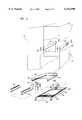
- FIG. 4is an exploded view of the cabinet and drawer, showing the cabinet in a cutaway view and showing various components of the drawer in perspective;
- FIG. 5is a side elevation view of a left side mounting rail for mounting the shelf, and the keyboard and monitor drawer to the rack of the cabinet;
- FIG. 6is a top view of the extensible left side mounting rail of FIG. 5;
- FIG. 7is a side elevation view of a right side mounting rail for mounting the shelf, and the keyboard and monitor drawer to the rack of the cabinet;
- FIG. 8is a top view of the right side mounting rail of FIG. 7;
- FIG. 9is a sectional view of the left side mounting rail, taken along Section Line 9--9 of FIG. 5;
- FIG. 10is a longitudinal section view of a bearing sleeve assembly for use in the right and left side mounting rails, taken along Section Line 9--9 of FIG. 5;
- FIG. 11is a sectional view of a mounting rail of the rack and a bar nut bracket for mounting the right said mounting rail to the rack, taken along Section Line 11--11 of FIG. 3;
- FIG. 12is a perspective view of an enclosure for mounting within the rack to provide the shelf;
- FIG. 13is a side elevation view of a cable guide bracket and a cable strap for securing keyboard, monitor and power cables;
- FIG. 14is a top view of a flexible cable arm having interconnecting linkages which are pivotally connected to the rearward end of the drawer and to a rear portion of the rack;
- FIG. 15is a side elevation view of the cable arm
- FIG. 16is a side elevation view of a telescoping, ball-bearing slide rail for slidably mounting the keyboard and monitor drawer to the enclosure and the rack;
- FIG. 17is an exploded view of the keyboard and monitor drawer, depicting various components thereof in perspective.
- FIGS. 18A and 18Bare exploded views depicting two clutch assemblies for pivotally mounting the monitor to the drawer, and retaining the monitor in selected angular positions when the flat screen monitor is disposed in such positions.
- FIG. 1is a cutaway view of a cabinet 10, preferably for a computer network server system, having a rack 12 and a door panel 14 which is pivotally mounted to the rack 12.
- the rackincludes a shelf 16 and a drawer 18, which is slidably mounted to the underside of the shelf 16.
- the drawer 18is moveable from within the rack 12 and the shelf 16 between an inward position to an outward position.
- the drawer 18is shown disposed in an intermediate position, which is disposed between the inward position and outward position.
- the rack 12is a nineteen inch wide rack.
- a monitor 20 and a keyboard 22are mounted within the drawer 18.
- the monitor 20is preferably a flatscreen monitor which is sized with a width which will fit within a nineteen inch wide rack, when mounted within the drawer 18.
- the drawer 18occupies a vertical space of two "U" vertical units, with one vertical unit of measure ("U") being equal to 1.75 inches.
- FIG. 2is a cutaway view of the cabinet 10, with the drawer 18 shown disposed in the inward position, substantially underneath the shelf 16 and substantially within the rack 12.
- the monitor 20has been lowered into a downwardly disposed, stowed position, prior to moving the drawer 18 into the inward position.
- the drawer 18must be moved from the intermediate position (shown in FIG. 1) to the outward position (shown in FIG. 3) so that the monitor 20 may be lowered into the downwardly disposed, stowed position.
- FIG. 3is a cutaway view of the cabinet 10, showing the drawer 18 after it has been pulled outward from underneath the shelf 16 and from within the rack 12 to the fully outward position, in which the drawer 18 is substantially disposed outward from underneath the shelf 16 and outward of the rack 12.
- the monitor 20is shown in the downward position.
- the drawer 18must preferably be fully in the outward position for the monitor to be moved from the downward, stowed position.
- the shelf 16is provided by two mounting rails 24 and 26, and an enclosure 28.
- the two mounting rails 24 and 26are disposed on opposite sides of the enclosure 28 and the drawer 18, and are extensible for self-adjusting to mount directly to rack 12.
- the enclosure 28is mounted to the mounting rails 24 and 26 and houses telescoping, ball bearing slide rail assemblies 30 and 32 for slidably mounting the drawer 18 underneath, or within, the enclosure 28 of the shelf 16.
- the drawer 18is mounted to the bearing slide assemblies 30 and 32 for moving from the inward position, in which the drawer is substantially disposed beneath the shelf 16, to the outward position, in which the drawer is disposed substantially outward from beneath the shelf 16.
- Opposite ends of a flexible cable arm 34are secured directly to the rearward end of the enclosure 28 and the rearward end of the drawer 18.
- the flexible cable arm 34is flexible such that it will move between extended and retracted positions as the drawer is moved inward and outward of the enclosure 28 and the rack 12.
- the flexible cable arm 34has multiple linkages which are preferably pivotally connected for pivotally moving relative to one another and parallel to a single plane within which the drawer moves in moving between the inward and outward positions.
- the forward end of the drawer 18has handles 36 and 38, and latches 40 and 42.
- the latches 40 and 42are preferably provided by captivated thumb screws for securing the drawer 18 to the rack 12, within the enclosure 28, when the drawer 18 is moved into the inward position, within the enclosure 28 and the rack 12.
- FIG. 4is an exploded, perspective of the cabinet 10.
- the shelf 16includes the self-adjusting mounting rails 24 and 26, which are shown extending within the rack 12. Four bar nuts 44 are provided for mounting respective ends of the two mounting rails 24 and 26 to the rack 12.
- the mounting rails 24 and 26are selectively extensible to automatically adjust in length for fitting with the horizontal depth of the rack 12, such that the mounted rails 24 and 26 are self-adjusting during mounting to automatically accommodate, or fit within, racks of various horizontal depths.
- the shelf 16further includes the enclosure 28, which is a structure having an open bottom, a closed top, two closed sides, an open forward end and a partially enclosed rearward end.
- the flexible cable arm 34has opposite ends which are mounted to respective ones of the rearward end of the enclosure 28 and the rearward end of the drawer 18.
- the telescoping, ball bearing slide assemblies 30 and 32are slidably mounted to the interior of the enclosure 28 and to the sides of the drawer 18.
- the telescopically adjustable lengths of the side rails 24 and 26, and the direction which the drawer 18 is moved when mounted to said slide assemblies 30 and 32are parallel, and extend within a singular plane within which the linkages of the cable arm 34 are pivotally moved.
- the drawer 18is shown with the flatscreen monitor 20 stowed in the downward position, disposed in a rearward portion of the drawer.
- the keyboard 22is mounted to a forward portion of the drawer 18.
- Also disposed in the forward portion of the drawer 18is a power supply 46 for powering the flatscreen monitor 20.
- Three cables 48extend rearward from the tray 202, providing data cables from the monitor 20 and keyboard 22, and a power cable for connecting the power supply 46 to a power source.
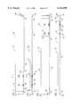
- FIG. 5is a side elevation view
- FIG. 6is a top view, of a left side mounting rail 24 for mounting the shelf 16 to the rack 12 (shown in phantom in FIGS. 1-4).
- the self-adjusting mounting rail 24mounts directly to the rack 12.
- the mounting rail 24includes a first section 52 and a second section 54. Flanges 56 and 58 are provided on the first section 52.
- the flange 56extends vertically for mounting the rail 24 to the forward end of the rack 12, with the flanges 56 and 58 disposed between the bar nuts 44 and a mounting rail of the rack 12.
- the flange 58extends horizontally and longitudinally along the length of the first section 52, providing a horizontal mounting surface for slidably receiving and then supporting the enclosure 28.
- the horizontally extending flange 58extends the full longitudinal length of the first section 52 of the left side mounting rail 24.
- a hole 60extends through the vertically extending sidewall of the first section 52 and a threaded nut 62 is mounted to the outward side of the first section 52, such that the nut 62 extends around the hole 60 for receiving a mounting screw which secures the forward end of the enclosure 28 to the left side mounting rail 24.
- Four holes 64are spaced apart and are provided through the vertically extending sides of the first section 52 of the left side mounting rail 24. The holes 64 are provided for aligning with slots 78 in the second section 54 of the left side mounting rail 24, which is discussed below in more detail.
- the first section 52has a rearward, terminal end 66.
- the second section 54 of the left side longitudinally adjustable mounting rail 24includes a rearward flange 72 which extends vertically for mounting directly to the rack 12.
- the second section 54also has a bend or fold 74 formed into a vertical wall therefor and extending between the flange 72 and the forward terminal end 76 of the second section 54.
- Four slots 78are formed in the vertical sidewall of the second section 54 and are disposed in a spaced apart alignment to extend in the longitudinal direction of the mounting rail 24. The four slots 78 are aligned for registering with the four spaced apart holes 64 of the first section 52 for cooperatively receiving respective ones of bearing sleeve assemblies 80.
- the bearing sleeve assemblies 80connect the first section 52 to the second section 54, such that the first section 52 is slidably engaged with the second section 54 for slidably moving in the direction of the longitudinal lengths of the slots 78.
- the longitudinal lengths of the slots 78preferably correspond to the longitudinal length of the mounting rails 24 and 26, which correspond to the horizontal depth of the rack 12.
- FIG. 7is a side elevational view of right side mounting rail 26, and FIG. 8 is a top view of the right side mounting rail 26.
- the right side mounting rail 26includes a first section 82 and a second section 84.
- the first section 82has a forward, vertically extending flange 56 and rearward terminal end 66.
- a horizontally extending flange 58extends the full, longitudinal length of the first section 82.
- a hole 60is formed through the vertically extending sidewall of the first section 82 and a threaded nut 62 is mounted to an outward side of the first section 82, such that the threaded nut 62 is aligned for receiving a fastening screw for mounting the forward end of the enclosure to the right side mounting rail 26.
- the second section 84has rearward flange 86 on the terminal end thereof, which includes a T-shaped section 88 and a vertically extending flange 90.
- the vertically extending flange 90is disposed at a right angle to the vertically extending surface of the T-shaped section 88.
- the flange 56 and the section 88are secured between the bar nuts 44 and the frame of the rack 12.
- Four slots 78are provided with longitudinal lengths that preferably extend parallel to the longitudinal length of the mounting rail 26.
- the four slots 78are aligned for registering with the four holes 64 formed through the vertical sidewall of the first section 82.
- the four holes 64register with the four slots 78 for receiving the bearing sleeve assemblies 80 to slidably couple the first section 82 to the second section 84, with the second section 84 being slidable relative to the first section 82 for the longitudinal lengths of the slots 78.
- FIG. 9is a sectional view of the left side mounting rail 24, taken along section 9--9 of FIG. 5.
- Four of the bearing sleeve assemblies 80are mounted within respective ones of the slots 78 and the holes 64.
- the first section 52is disposed inside of the second section 54.
- the horizontally extending flange 58is shown extending inward from the bottom of the first section 52.
- the second section 54is slidably coupled to the first section 52 by the four bearing sleeve assemblies 80 (two shown).
- a threaded nut 92is used for coupling the bearing sleeve assembly 80 to the first section 52 and the second section 54 of the mounting rail 24.
- the right side mounting rail 26is configured similar to the left side mounting rail 24, with the exception of the flange 58 of the right side mounting rail extends inward, in an opposite facing direction to that of the flange 58 of the left side mounting rail 24, and the first section 82 is disposed inside of the second section 84.
- the flange 58provides a surface upon which the drawer 18 (shown in a cutaway view) may slide and rest during installation of the slide assemblies 30 and 32.
- FIG. 10is a longitudinal section view of one of the bearing sleeve assemblies 80.
- the bearing sleeve assembly 80includes a threaded fastener 94 having a shank 96 and head 98.
- the head 98has a combination torx drive and single slot drive connection 100 formed into the same hole, such that the connection 100 can be coupled to and driven by either a torx drive or a flat head screw driver.
- An end 102 of the shank 96, which is opposite the head 98,is threaded for coupling to one of the threaded nuts 92 (shown in FIG. 9).
- a bearing surface 104is provided on the intermediate portion of the shank 96, which is adjacent to the head 98.
- An annularshaped bearing sleeve 106has an inner bearing surface 108 which extends around the upward bearing surface 104 of the shank 96, adjacent to the head 98.
- An outer bearing surface 110 of the bearing sleeve 106will engage within the slot 78 of the second section 54 to provide a rolling surface for relative movement between respective ones of the first section 52 and the second section 54, and the first section 82 and the second section 84, for extending and retracting the mounting rails 24 and 26.
- FIG. 11is a sectional view of one of four cabinet bay mounting rails 112 of the rack 12 and one of the four bar nut brackets 44 for mounting the right said mounting rail 26 to the rack 12, taken along Section Line 11--11 of FIG. 11.
- the mounting rails 112preferably extend for the vertical height of the rack 12, one on each of the four comers of each bay of the rack 12 to provide flanges for rigidly securing various members to the rack 12.
- the mounting rails 112have holes 114 which are spaced apart for the full height of the mounting rails 112.
- the bar nut brackets 44have upper and lower terminal ends 115.
- a U-shaped section 116is secured to fit flush against the mounting rails 112 and formed to provide an offset section as a means for spacing apart a straight section 117 of the bracket from the rail 112.
- the straight section 117extends from the U-shaped section 116, spaced apart from the mounting rail 112 of the rack 12 for fitting a tab means provided by the flange 86 of the T-shaped section 88 of the right side mounting rail 26.
- Five threaded holes 118are provided in the bar nut bracket 44. Three of the holes 118 are aligned for registering with three of the holes 119 of the tab portion of the flange 86 and three of the holes 114 in the cabinet bay mounting rails 112.
- the one of the threaded holes 118 disposed in the U-shaped section 116is aligned with one of the holes 114 in the cabinet bay mounting rail 112 to secure the bar nut bracket to the rack 12.
- One of the threaded holes 118 in the straight portion 118 of the bracket 44is aligned with one of the holes 114 for receiving a threaded shank of the captivated thumb screw used for the latch 42 (shown in FIG. 3).
- the longitudinal terminal ends of the mounting rails 24 and 26are secured by respective ones of the four flanges 56 and 86 to respective ones of the bar nut brackets 44 and the mounting rails 112 of the rack 12, with two screws threadingly engaging the holes 118 of the brackets 44 for each of the four flanges 56 and 86.
- the self-adjusting mounting rails24 and 26are easily mounted within the rack 12, by first securing the bar nut brackets 44 to the cabinet bay mounting rails 112, then fitting the longitudinal length of the mounting rails 24 and 26 to match the horizontal depth of the cabinet 12 using the telescoping, self-adjusting feature of the mounting rails 24 and 26, and lastly securing the four flanges 56 and 86 of the four terminal ends of the mounting rails 24 an 26 to respective ones of the cabinet bay mounting rails 112 using two screws to engage the threaded holes 118 of the bar nut brackets 44.
- FIG. 12is a cutaway view of the enclosure 28 for use in mounting the drawer 18 to the rack 12 to provide the shelf 16.
- the enclosure 28comprises a metal fabrication 120 which, when oriented as viewed from the front of the cabinet 10 when installed therein, has a top 122, a right side 124, a left side 126 and an open bottom 128.
- Flanges 130are horizontal and formed to extend inward from respective ones of the right side 124 and the left side 126, into the open bottom 128.
- the enclosure 28further has an open forward end 132 and a partially enclosed rearward end 134.
- the rearward end 134is formed from a solid, planar sheet having a rectangular port 136, a rectangular port 138, and an oval or round port 140.
- a cable guide bracket 142is mounted to the rearward end 134.
- FIG. 13is a side elevation view of the cable guide bracket 142.
- the cable guide bracket 142includes the cable strap 144 which has a VELCROTM connection on the upper and lower ends, a mounting plate 146 and a guide flange 148.
- the mounting plate 146has a planar surface for fitting flush against the planar rearward end 134 of the enclosure 28.
- the guide flange 148extends at an angle of approximately thirty degrees (30°) to the planar surface of the mounting plate 146 for mounting at an angle to the rearward end 134 of the enclosure 128 (shown in FIG. 12), for guiding the keyboard, monitor and power cables at an angle from the rearward end 134, to prevent these cables from hitting the rearward end of the rack 12.
- the cable strap 144is wrapped around the guide flange 148 and the ends thereof are secured together, to secure the keyboard, monitor and power cables therein, with the strap 144 being wrapped around a guide flange 148 of the cable guide bracket 142.
- FIG. 14is a top view and FIG. 15 is a side elevation view of the cable arm 34.
- the cable arm 34includes a forward linkage 162, an intermediate linkage 164 and a rearward linkage 166.
- the cable arm 34further includes a forward mounting bracket 168 and a rearward mounting bracket 170.
- the forward linkage 162is preferably shorter than the rearward linkagel66, and the intermediate linkage 164 is significantly shorter than the forward linkage 162 and the rearward linkage 166.
- Four hinges 172interconnect respect ones of the forward mounting bracket 168, the forward linkage 162, the intermediate linkage 164, the rearward linkage 166 and the rearward mounting bracket 170.
- a plurality of flat plate mounting brackets 174are utilized for mounting the hinges 172 to respective ones of the above linkages and brackets 162 through 170.
- the cable armis flexible since linkages 162, 164 and 166 are pivotally connected for angularly moving relative to one another within a singular horizontal plane which is parallel to a horizontal plane within which said drawer 18 moves relative to said rack 12.
- the forward mounting bracket 168is connected directly to the rearward end of the drawer 18 and the rearward mounting bracket 170 is connected directly to the rearward end 134 of the enclosure 28.
- the rearward mounting bracket 170further includes an outward flange portion 176.
- the outward flange portion 176provides a planar surface which is mounted flush against the forward facing side of the partially enclosed rearward end 134 of the enclosure 28.
- Quick-release fastenersare preferably used for connecting the rearward mounting bracket 170 to the rearward end 134 of the enclosure 28.
- the fastenersprovide a quick release for quickly coupling and quickly releasing the cable arm 34 from the rearward end 134 of the enclosure 28 during assembly and during removal of the drawer 18 from within the rack 12.
- a plurality of the cable straps 144are mounted to the linkages 162, 164 and 166 for wrapping around respective ones of the linkages 162, 164 and 166 to secure the keyboard, monitor and power cables to the cable arm 34.
- the cable arm 34provides a means for holding the three cables and preventing the three cables from being entrapped between the drawer 18 and the enclosure 28 as the drawer 18 is moved between the intermediate, inward and outward positions (shown in FIGS. 1 through 3, respectively).
- FIG. 16is a side elevation view of the telescoping, ball bearing slide rail assembly 32, which mounts to the interior of the right vertical sidewall 124 of the enclosure 28 and the exterior of the right vertical sidewall of the drawer 18.
- the telescoping, ball bearing slide rail assembly 30is constructed similarly to the slide rail 32, except being oriented for mounting to an opposite side of the drawer 18.
- the slide rail 32includes a rack rail 182 which is rigidly mounted directly to the interior of the enclosure 28.
- the bearing housing 184includes a lower track 186 and an upper track 188 which have ball bearings for slidably receiving respective ones of the rack rail 182 and the drawer rail 192.
- the drawer rail 192is rigidly mounted directly to the sides of the drawer 18, and is slidably engaged within the upper track 188 for riding upon ball bearings housed within the slide rail bearing housing 184.
- the forward end 194 of the bearing housing 184has a notch 196.
- This notch 196is used for passing a mounting screw by which the enclosure 28 is rigidly secured to the mounting rails 26, and thereby to the rack 12.
- a second notch 196(not shown) is also provided in the forward end of the telescoping, ball bearing slide rail assembly 30 for passing a mounting screw for mounting the enclosure 28 to the mounting rail 24.
- a latchengages the drawer rails 192 in an outward position relative to the housing 184.
- the housing 184preferably does not have a latch to maintain the housing 184 in a selected position relative to the drawer slide rail 182.
- FIG. 17is an exploded, cutaway view of the keyboard and monitor drawer 18.
- the drawer 18includes in a tray 202, which is preferably formed of a metal fabrication. Two raised mounting surfaces 204 are provided at a height that is spaced above the bottom of the tray 202. An opening 206 is provided in the rearward end of the tray 202 for passing the keyboard, monitor and power cables. Three holes 208 are provided for mounting the forward mounting bracket 168 of the cable arm 34 to the rearward end of the tray 202.
- a monitor platform 212is provided for mounting the flatscreen monitor 20 to the tray 202.
- the monitor platform 212includes a back plate 214 and two mounting brackets 216 and 218. The backside of the flatscreen monitor 20 is mounted to the backplate 214.
- the mounting brackets 216 and 218provide mounting feet which fit flush against the two raised mounted surfaces 204 formed into the bottom of the tray 202.
- Two backplate brackets 220 and 222rotatably secure the back plate 214 to respective ones of the mounting brackets 216 and 218.
- Clutch assemblies 224 and 226are mounted to respective ones of the brackets 216 and 218, and the two backplate brackets 220 and 222.
- the clutch assemblies 224 and 226provide frictional engagement members which retain the back plate 214 and the flatscreen monitor 20 in an upright position.
- a keyboard mounting platform 232is also included in the drawer 18.
- the platform 232is provided by a metal fabrication 234 having standoffs 236 and 238 which space apart the upper platform surface of the platform 232 from the bottom of the tray 202 providing a space 240 therebetween.
- Power supply 46(shown in FIG. 4) for the monitor 20 is mounted in the space 240.
- Two tabs 242provide a stop on the rearward end on the platform 232.
- a mounting bracket 244extends downward for mounting the rearward end of the platform 232 to the bottom of the tray 202.
- a raised surface 246is provided in the forward end of the platform 232, and preferably includes a gel-type wrist pad 248.
- FIGS. 18A and 18Bare exploded top views of the two clutch assemblies 224 and 226, respectively.
- the mounting brackets 216 and 218mount directly to the raised mounting surfaces 204 of the bottom of the tray 202 of the drawer 18.
- the backplate brackets 220 and 222each have a shoulder 262.
- the backplate mounting brackets 222 and 220each also include a shank 264 with a threaded outward end 266.
- a bracket washer 268has a flat portion which mounts directly against the shoulder 262, and an outward end which extends at a right angle to the flat portion and engages the top of respective ones of the brackets 216 and 218, to provide a stop which engages the tops of respective ones of the brackets 216 and 218.
- Belleville-type washers 270 and flat washers 272are secured between the nuts 274 and respective ones of the mounting brackets 216 and 218 to provide a spring force which presses the flat washers 272 against the upwardly extending surfaces of respective ones of the brackets 216 and 218.
- the belleville-type washers 270push against the outer perimeter portions of the flat washers 272, which press against the upwardly extending surfaces of respective ones of the brackets 216 and 218 provide the frictional engagement for retaining the backplate 212 and the flatscreen monitor in an upright position relative to the drawer 18.
- the belleville-type washers 270 and the flat washers 272together provide a frictional engagement means having frictional engagement members, or retaining members, for retaining the backplate 214 in a selected angular position relative to the tray 202.
- the two self-adjusting mounting rails 24 and 26are first mounted within the rack 12. During placement into the rack 12, the two selfadjusting mounting rails 24 and 26 are preferably free to telescopically extend and retract, until the opposite longitudinal ends of the mounting rails 24 and 26 are secured to opposite ends of the rack 12.
- the forward and rearward ends of the mounting rails 24 and 26 togetherhave four flanges 56 and 86 which are threadingly secured to the rack 12, with the flanges 56 and 86 fitting between the cabinet mounting rail 112 of the rack 12 and the bar nuts 44.
- the enclosure 28is then secured into the rack 12 to provide the shelf 16, with the lower edges of the enclosure 28 fitting upon the two inwardly extending, horizontal flanges 58 of the mounting rails 24 and 26.
- the rack rails 182are mounted to the inward facing surfaces of the sidewalls of the enclosure 28.
- the two bearing housings 184 of the telescoping slide assemblies 30 and 32may be installed to the rack with the enclosure 28, or, in the alternative, the two bearing housings 184 of the assemblies 30 and 32 may be installed into the enclosure 28 after the enclosure 28 is mounted to the rack 12.
- the keyboard 22, the flatscreen monitor 20, the power supply 46, the cable arm 34 and the slide rails 192are first mounted to the tray 202 of the drawer 18.
- the three cables for respective ones of the monitor 20, the keyboard 22 and the power supply 46are attached to the cable arm 34 with the cable straps 144.
- the slide rails 192are engaged within the slide housing 190 and the drawer 18 is moved rearward and partially within the enclosure 28 to moveably secure the drawer 18 to the shelf 16.
- the end of the cable arm 34is then secured to the rearward end of the enclosure 28 with the quick fasteners 150.
- the keyboard, monitor and power cablesare feed through the port 140, being diverted by the guide flange 148 of the guide bracket 142 to extend from within the enclosure 28 at a sixty degree angle to the planar surface of the partially enclosed rearward end 134 of the enclosure 28.
- the ports 136 and 138provide access for viewing the cable arm 34 and reaching within the enclosure 28 from rearward of the drawer 18 to guide the rearward end of the cable arm 34 for securing to the right side of the rearward end 134 and guiding the three cables through the port 140.
- the handles 36may be grasped for gripping the drawer, and the latches 40 and 42 may be threadingly secured to the threaded holes in the forward two of the bar nuts 44, to fasten the drawer 18 within the shelf 16 and the rack 12.
- the drawer 18is then operational for moving between the inward, intermediate and outward positions, relative to the shelf 16 and the rack 12, after releasing the latches 40 and 42.
- the drawerwill be initially in the position shown in FIG. 2, with the monitor 20 in the downward, stowed position and the drawer 18 in the inward position, substantially within the rack 12. Then, the drawer will be extended outward to the fully outward position as shown in FIG. 3, providing clearance for the flatscreen monitor 20 to be pivoted upwards to the upright position, as the monitor is shown in relation to the drawer 18 in FIG. 1. Then, the drawer will be pushed backwards to the intermediate position as shown in FIG. 1, such that the monitor 20 is in the upright position and in front of the rack 12.
- the clutch assemblies 224 and 226will hold the flatscreen monitor in the upright position, or in an intermediate position between the downward stowed position and the upright position.
- the drawer 18is pulled outward to the fully outward position shown in FIG. 3, and the monitor 20 will be moved downward to the stowed position shown in FIG. 3. Then, the drawer 18 will be moved inward to the inward position shown within the rack 12 in FIG. 2.
- the drawer 18 of the present inventionis provided having a two "U" vertical height, preferably for use in 19 inch wide racks.
- the drawer 18is mounted within a shelf 16 provided by the enclosure 28, which is mounted within the rack by selfadjusting mounting rails 24 and 26.
- Two slide rails 182are rigidly mounted to opposite, interior sides of the enclosure 28.
- the telescoping slide rail bearing assemblies 30 and 32are then slidingly mounted to the two side rails 182, to telescopically extend from within the enclosure 28.
- the bearing assemblies 30 and 32each include a sliding bearing housing 190, which is slidingly mounted a main bearing housing of the two bearing assemblies 30 and 32.
- the slide rails 192are rigidly mounted directly to the sides of the drawer 18, and then the slide rails 192 are slidingly engaged within sliding bearing housing 190, which slidingly engages the slide rail bearing assemblies 30 and 32.
- a flexible cable arm 34is provided for retaining the three cables, which are the keyboard, monitor and power cables. The cable arm 34 is flexible for extending and retracting between the rear of the tray 18 and the rearward end of the enclosure 28.
- the flatscreen monitor 20is pivotally mounted to the drawer 18 by means of the backplate bracket 212, the two mounting brackets 216 and 218, the two backplate mounting brackets 220 and 262, and the clutch assemblies 224 and 226.
- a keyboard 22is also mounted within the drawer 18.
- a power supply 46 for powering the monitor 20is mounted directly underneath the keyboard 22 within the drawer 18.
Landscapes
- Engineering & Computer Science (AREA)
- General Engineering & Computer Science (AREA)
- Theoretical Computer Science (AREA)
- Human Computer Interaction (AREA)
- Physics & Mathematics (AREA)
- General Physics & Mathematics (AREA)
- Computer Hardware Design (AREA)
- Microelectronics & Electronic Packaging (AREA)
- Drawers Of Furniture (AREA)
- Casings For Electric Apparatus (AREA)
Abstract
Description
Claims (18)
Priority Applications (1)
| Application Number | Priority Date | Filing Date | Title |
|---|---|---|---|
| US09/286,192US6142590A (en) | 1999-04-05 | 1999-04-05 | Two U vertical height keyboard and flatscreen drawer for a server system rack |
Applications Claiming Priority (1)
| Application Number | Priority Date | Filing Date | Title |
|---|---|---|---|
| US09/286,192US6142590A (en) | 1999-04-05 | 1999-04-05 | Two U vertical height keyboard and flatscreen drawer for a server system rack |
Publications (1)
| Publication Number | Publication Date |
|---|---|
| US6142590Atrue US6142590A (en) | 2000-11-07 |
Family
ID=23097494
Family Applications (1)
| Application Number | Title | Priority Date | Filing Date |
|---|---|---|---|
| US09/286,192Expired - Fee RelatedUS6142590A (en) | 1999-04-05 | 1999-04-05 | Two U vertical height keyboard and flatscreen drawer for a server system rack |
Country Status (1)
| Country | Link |
|---|---|
| US (1) | US6142590A (en) |
Cited By (74)
| Publication number | Priority date | Publication date | Assignee | Title |
|---|---|---|---|---|
| US6424534B1 (en)* | 2000-10-26 | 2002-07-23 | Hewlett-Packard Company | Computer enclosure rack mounting system |
| US6422399B1 (en) | 2000-11-21 | 2002-07-23 | Dell Products L.P. | Rack system and method having tool-less releasable arm assembly |
| US20020104942A1 (en)* | 2000-11-07 | 2002-08-08 | Mimlitch Robert H. | Apparatus and method for adapting two-post rack systems to support four-post rack mounted equipment |
| US6442030B1 (en)* | 2001-04-26 | 2002-08-27 | Central Industrial Supply Company, Inc. | Server system rack drawer with keyboard, flat panel display and electronic switch |
| US6497465B1 (en)* | 2000-09-21 | 2002-12-24 | International Business Machines Corporation | Anti-tilt mechanism for a drawer assembly |
| US6523918B1 (en)* | 2001-04-24 | 2003-02-25 | Central Industrial Supply Company, Inc. | Pivot mounting bracket with toolless fastener for a server rack |
| US20030052580A1 (en)* | 2001-09-19 | 2003-03-20 | Dobler Karl J. | Snap-on slide and rail assembly and method of assembling same |
| US20030054329A1 (en)* | 2001-09-14 | 2003-03-20 | Springett David Roy | Portable computer classroom with high speed two-way network access |
| US6554142B2 (en) | 2001-07-27 | 2003-04-29 | Dell Products L.P. | Variable mount rack system arm assembly |
| US6563700B1 (en)* | 2001-02-23 | 2003-05-13 | Crystal Group Inc. | Method and system for deploying a display and keyboard in a rack |
| DE10157319C1 (en)* | 2001-11-23 | 2003-05-22 | Rittal Gmbh & Co Kg | Keyboard drawer for switchgear cabinet has mousepad fitting over computer keyboard and computer mouse in stowed position |
| EP1303173A3 (en)* | 2001-10-09 | 2003-06-11 | Fujitsu Siemens Computers GmbH | Server |
| US20030107309A1 (en)* | 2001-12-06 | 2003-06-12 | Lauchner Craig E. | Dual flat springs for tool-less slide installation |
| US6589308B1 (en)* | 1997-02-28 | 2003-07-08 | Angelo Gianelo | Cabinet for housing a computer workstation |
| US20030142064A1 (en)* | 2002-01-28 | 2003-07-31 | Tony Wang | Display observation angle of which is multidirectionally adjustable |
| US6622873B2 (en) | 2001-06-20 | 2003-09-23 | International Business Machines Corporation | Self-aligning, single person installable rack rail/alignment plate assembly |
| EP1260886A3 (en)* | 2001-05-23 | 2003-11-05 | ABB Sace S.p.A. | Home automation system |
| US20030222034A1 (en)* | 2002-05-31 | 2003-12-04 | International Business Machines Corporation | Electrical equipment rack and cable management arm assembly |
| US20030227753A1 (en)* | 2002-06-10 | 2003-12-11 | Wrycraft Sean Conor | Cable management system |
| US20030226812A1 (en)* | 2002-06-10 | 2003-12-11 | Wrycraft Sean Conor | Cable management system |
| US20040016709A1 (en)* | 2001-06-04 | 2004-01-29 | Chris Felcman | System and method for mounting a keyboard and display assembly in a 1U rack space |
| DE10252526B3 (en)* | 2002-11-08 | 2004-05-06 | Rittal Gmbh & Co. Kg | Personal computer cabinet having integrated keyboard and monitor screen, with rear wall of monitor screen acting as cover for keyboard when not in use |
| US20040090159A1 (en)* | 2002-11-11 | 2004-05-13 | Kazuhiro Tsutsumi | Guiding and holding jig for a flexible connector in a pull-out unit |
| US20040108289A1 (en)* | 2002-12-06 | 2004-06-10 | King Slide Works Co., Ltd. | Detachable device of a cable management arm for furniture |
| US6769551B2 (en) | 2002-07-26 | 2004-08-03 | Dell Products L.P. | System and method for utilizing non-dedicated rack space |
| US6772887B2 (en)* | 2000-12-19 | 2004-08-10 | The Siemon Company | Rack mountable fiber splice and patch enclosure |
| US20040182798A1 (en)* | 2003-03-21 | 2004-09-23 | Dell Products L.P. | Tool-less cable management attachment bracket and method of use |
| US20050035262A1 (en)* | 2003-08-15 | 2005-02-17 | Fujitsu Component Limited | Movable console device |
| US6866154B2 (en) | 2002-12-03 | 2005-03-15 | Dell Products L.P. | Tool-less attachment bracket |
| US20050067358A1 (en)* | 2003-09-30 | 2005-03-31 | Dell Products L.P. | Cable management flip tray assembly |
| US20050072745A1 (en)* | 2003-10-02 | 2005-04-07 | Schmidtk Gregg S. | Apparatus and method for mounting a device to a rack system |
| US6902069B2 (en) | 2002-10-23 | 2005-06-07 | Dell Products L.P. | System and method for rack cable management |
| US20050211647A1 (en)* | 2004-03-29 | 2005-09-29 | Emc Corporation | Tray with integrated rail guides for facilitating installation of equipment units into a cabinet rack |
| US20050225217A1 (en)* | 2004-04-10 | 2005-10-13 | International Business Machines Corporation | Adjustable rack mountable computer terminal mounting system |
| US6962397B2 (en) | 2001-09-19 | 2005-11-08 | Hewlett-Packard Development Company, L.P. | Expandable slide and rail assembly for a rack |
| US6988626B2 (en)* | 1998-07-31 | 2006-01-24 | Varghese Paily T | Computer component rack mounting arrangement |
| US7009112B1 (en) | 2004-09-28 | 2006-03-07 | Lockheed Martin Corporation | Cable organization apparatuses and systems |
| US7012808B2 (en) | 2002-12-20 | 2006-03-14 | Hewlett-Packard Development Company, L.P. | Multi-configurable telecommunications rack mounting system and method incorporating same |
| US20060232718A1 (en)* | 2005-04-14 | 2006-10-19 | Chen-Sung Liao | Display apparatus |
| US7137512B2 (en) | 2003-02-19 | 2006-11-21 | Hewlett-Packard Development Company, L.P. | Removable rails for use on racks |
| US7201279B1 (en)* | 2002-07-18 | 2007-04-10 | Innovation First, Inc. | Sliding rack-mountable shelf for rack-mountable components |
| US20070175837A1 (en)* | 2005-11-08 | 2007-08-02 | Furman Lawrence J | System and method for providing access to the keyboard and display assembly of rack mounted computing systems when the rack door remains closed |
| US7258583B1 (en) | 2005-01-31 | 2007-08-21 | Central Industrial Supply Company | Cable management arm having cable retention members |
| US20080084673A1 (en)* | 2006-10-05 | 2008-04-10 | William Tse Lin Hsiung | Retaining structure for mounting two independent computers within one standard slot in a computer cabinet |
| US20080164789A1 (en)* | 2003-03-21 | 2008-07-10 | Dell Products L.P. | Tool-less Cable Management Attachment Bracket And Method Of Use |
| US20080169737A1 (en)* | 2007-01-16 | 2008-07-17 | Min-Dy Shen | Adjustable Pull-Out Frame Structure |
| US20080278889A1 (en)* | 2004-01-23 | 2008-11-13 | American Power Conversion Corporation | Modular ups |
| DE102007026316B3 (en)* | 2007-06-06 | 2008-12-04 | Fujitsu Siemens Computers Gmbh | Device for current supply for rack insertion device in rack, has carrier rail, which comprises electrically conductive connection for contacting installation device at conductor rail displaced in rack |
| US20090218301A1 (en)* | 2002-03-14 | 2009-09-03 | Innovation First, Inc., A Texas Corporation | Universal rack mountable shelf |
| US20090224639A1 (en)* | 2008-03-07 | 2009-09-10 | Telco Technologies, Inc. | Enclosure for Electronic Equipment |
| US7591383B1 (en)* | 2000-04-07 | 2009-09-22 | Sun Microsystems, Inc. | Rack mountable display apparatus |
| US20100008029A1 (en)* | 2005-05-13 | 2010-01-14 | Farshad Shahrokhi | Cable Management System for a Movable Display Device |
| US20100046161A1 (en)* | 2008-08-25 | 2010-02-25 | Chi-Tsun Cheng | Rail assembly for an industrial computer |
| US20100072869A1 (en)* | 2008-09-25 | 2010-03-25 | Inventec Corporation | Cabinet and cable chain thereof |
| KR200448314Y1 (en)* | 2007-08-10 | 2010-04-01 | 김철 | Height Adjustable Monitor Stand |
| US20100123377A1 (en)* | 2008-11-20 | 2010-05-20 | Inventec Corporation | Cabinet |
| US20110317971A1 (en)* | 2008-05-12 | 2011-12-29 | Adc Communications (Shanghai) Co., Ltd. | Cable management panel |
| US20120188725A1 (en)* | 2011-01-24 | 2012-07-26 | Kabushiki Kaisha Yaskawa Denki | Electrical instrument |
| US20120280602A1 (en)* | 2011-05-02 | 2012-11-08 | Baker James F | Mobile Electronic Device Cabinet |
| US8695510B2 (en) | 2011-06-10 | 2014-04-15 | Haworth, Inc. | Table with storable monitor |
| US20140205394A1 (en)* | 2013-01-18 | 2014-07-24 | Wistron Corporation | Locking device |
| US20140293527A1 (en)* | 2013-03-27 | 2014-10-02 | International Business Machines Corporation | Multi-directional display console for an electronic equipment cabinet |
| US9173312B1 (en)* | 2014-04-30 | 2015-10-27 | Quanta Computer Inc. | Cable storage under a drawer |
| US20160021778A1 (en)* | 2014-07-16 | 2016-01-21 | Quanta Computer Inc. | Server |
| US20170020023A1 (en)* | 2015-07-14 | 2017-01-19 | Wistron Corporation | Server kit capable of supporting storage devices, server slide rail applied to server kit, and related server system |
| US9801308B2 (en)* | 2016-03-09 | 2017-10-24 | Dell Products Lp | Managing cable connections and air flow in a data center |
| US20170332509A1 (en)* | 2014-10-30 | 2017-11-16 | Fujitsu Component Limited | Kvm switch, mounting bracket and system |
| US20180014419A1 (en)* | 2016-07-05 | 2018-01-11 | Snap-On Equipment Srl A Unico Socio | Machine body for a wheel servicing apparatus with display support unit |
| US10433464B1 (en)* | 2016-06-06 | 2019-10-01 | ZT Group Int'l, Inc. | Air duct for cooling a rear-mounted switch in a rack |
| WO2019236103A1 (en)* | 2018-06-08 | 2019-12-12 | Hewlett-Packard Development Company, L.P. | Slidable keyboards |
| CN113115552A (en)* | 2021-04-07 | 2021-07-13 | 南京清铭宇自控科技有限公司 | Wireless pressure remote control end device based on ROLA communication |
| CN113676381A (en)* | 2021-10-25 | 2021-11-19 | 深圳市擎联科技有限公司 | Cloud server real-time monitoring device and method based on cloud computing |
| US11659679B1 (en)* | 2021-10-22 | 2023-05-23 | ZI Group Int'l, Inc. | Telescoping cabinet rail |
| US12262501B2 (en) | 2021-05-25 | 2025-03-25 | Vertiv Corporationn | Low profile keyboard, monitor and mouse in rack |
Citations (11)
| Publication number | Priority date | Publication date | Assignee | Title |
|---|---|---|---|---|
| US3133768A (en)* | 1960-01-11 | 1964-05-19 | Markline Electronic Products I | Extensible chassis slide |
| US3606112A (en)* | 1970-01-28 | 1971-09-20 | Leonard A Cheshier | Retractable beverage holder for motor vehicles |
| US4614383A (en)* | 1984-12-31 | 1986-09-30 | General Dynamics, Electronics Division | Cable carrier/retractor |
| US5161028A (en)* | 1989-07-20 | 1992-11-03 | Kabushiki Kaisha Toshiba | Car-mounted video displaying apparatus |
| US5213401A (en)* | 1991-05-17 | 1993-05-25 | Posting Equipment Corporation | Support for computer terminal and computer keyboard |
| US5388032A (en)* | 1993-05-04 | 1995-02-07 | Ibus Technologies, Inc. | Computer equipment monitor and discriminator |
| US5443312A (en)* | 1994-04-07 | 1995-08-22 | Schluter; Robert J. | Rack assembly for facilitating access to wall and cabinet-mounted serviceable equipment |
| US5460441A (en)* | 1994-11-01 | 1995-10-24 | Compaq Computer Corporation | Rack-mounted computer apparatus |
| US5568775A (en)* | 1995-01-23 | 1996-10-29 | Knoll, Inc. | Articulating table connection |
| US5833337A (en)* | 1997-05-09 | 1998-11-10 | Sequent Computer Systems, Inc. | Self-retaining rack slide |
| US5946055A (en)* | 1996-08-16 | 1999-08-31 | Rosen Product Development, Inc. | Display unit |
- 1999
- 1999-04-05USUS09/286,192patent/US6142590A/ennot_activeExpired - Fee Related
Patent Citations (11)
| Publication number | Priority date | Publication date | Assignee | Title |
|---|---|---|---|---|
| US3133768A (en)* | 1960-01-11 | 1964-05-19 | Markline Electronic Products I | Extensible chassis slide |
| US3606112A (en)* | 1970-01-28 | 1971-09-20 | Leonard A Cheshier | Retractable beverage holder for motor vehicles |
| US4614383A (en)* | 1984-12-31 | 1986-09-30 | General Dynamics, Electronics Division | Cable carrier/retractor |
| US5161028A (en)* | 1989-07-20 | 1992-11-03 | Kabushiki Kaisha Toshiba | Car-mounted video displaying apparatus |
| US5213401A (en)* | 1991-05-17 | 1993-05-25 | Posting Equipment Corporation | Support for computer terminal and computer keyboard |
| US5388032A (en)* | 1993-05-04 | 1995-02-07 | Ibus Technologies, Inc. | Computer equipment monitor and discriminator |
| US5443312A (en)* | 1994-04-07 | 1995-08-22 | Schluter; Robert J. | Rack assembly for facilitating access to wall and cabinet-mounted serviceable equipment |
| US5460441A (en)* | 1994-11-01 | 1995-10-24 | Compaq Computer Corporation | Rack-mounted computer apparatus |
| US5568775A (en)* | 1995-01-23 | 1996-10-29 | Knoll, Inc. | Articulating table connection |
| US5946055A (en)* | 1996-08-16 | 1999-08-31 | Rosen Product Development, Inc. | Display unit |
| US5833337A (en)* | 1997-05-09 | 1998-11-10 | Sequent Computer Systems, Inc. | Self-retaining rack slide |
Cited By (122)
| Publication number | Priority date | Publication date | Assignee | Title |
|---|---|---|---|---|
| US6589308B1 (en)* | 1997-02-28 | 2003-07-08 | Angelo Gianelo | Cabinet for housing a computer workstation |
| US6988626B2 (en)* | 1998-07-31 | 2006-01-24 | Varghese Paily T | Computer component rack mounting arrangement |
| US7591383B1 (en)* | 2000-04-07 | 2009-09-22 | Sun Microsystems, Inc. | Rack mountable display apparatus |
| US6497465B1 (en)* | 2000-09-21 | 2002-12-24 | International Business Machines Corporation | Anti-tilt mechanism for a drawer assembly |
| US6424534B1 (en)* | 2000-10-26 | 2002-07-23 | Hewlett-Packard Company | Computer enclosure rack mounting system |
| US7591056B2 (en) | 2000-11-07 | 2009-09-22 | Innovation First, Inc. | Method for adapting two-post rack systems to support four-post rack mounted equipment |
| US7275646B2 (en) | 2000-11-07 | 2007-10-02 | Innovation First, Inc. | Apparatus and method for adapting two-post rack systems to support four-post rack mounted equipment |
| US20020104942A1 (en)* | 2000-11-07 | 2002-08-08 | Mimlitch Robert H. | Apparatus and method for adapting two-post rack systems to support four-post rack mounted equipment |
| US20080175659A1 (en)* | 2000-11-07 | 2008-07-24 | Innovation First, Inc. | Apparatus and method for adapting two-post rack systems to support four-post rack mounted equipment |
| US6422399B1 (en) | 2000-11-21 | 2002-07-23 | Dell Products L.P. | Rack system and method having tool-less releasable arm assembly |
| US6772887B2 (en)* | 2000-12-19 | 2004-08-10 | The Siemon Company | Rack mountable fiber splice and patch enclosure |
| US6807054B1 (en) | 2001-02-23 | 2004-10-19 | Crystal Group Inc. | Method and system for deploying a display and keyboard in a rack |
| US6563700B1 (en)* | 2001-02-23 | 2003-05-13 | Crystal Group Inc. | Method and system for deploying a display and keyboard in a rack |
| US6523918B1 (en)* | 2001-04-24 | 2003-02-25 | Central Industrial Supply Company, Inc. | Pivot mounting bracket with toolless fastener for a server rack |
| US6726164B1 (en)* | 2001-04-26 | 2004-04-27 | Central Industrial Supply, Company, Inc. | Mounting bracket having a tapered plunger latch |
| US6442030B1 (en)* | 2001-04-26 | 2002-08-27 | Central Industrial Supply Company, Inc. | Server system rack drawer with keyboard, flat panel display and electronic switch |
| EP1260886A3 (en)* | 2001-05-23 | 2003-11-05 | ABB Sace S.p.A. | Home automation system |
| US6945412B2 (en)* | 2001-06-04 | 2005-09-20 | Hewlett-Packard Development Company, L.P. | System and method for mounting a keyboard and display assembly in a 1U rack space |
| US20040016709A1 (en)* | 2001-06-04 | 2004-01-29 | Chris Felcman | System and method for mounting a keyboard and display assembly in a 1U rack space |
| US6622873B2 (en) | 2001-06-20 | 2003-09-23 | International Business Machines Corporation | Self-aligning, single person installable rack rail/alignment plate assembly |
| US6554142B2 (en) | 2001-07-27 | 2003-04-29 | Dell Products L.P. | Variable mount rack system arm assembly |
| US20030054329A1 (en)* | 2001-09-14 | 2003-03-20 | Springett David Roy | Portable computer classroom with high speed two-way network access |
| US6976745B2 (en) | 2001-09-19 | 2005-12-20 | Hewlett-Packard Development Company, L.P. | Snap-on slide and rail assembly |
| US6962397B2 (en) | 2001-09-19 | 2005-11-08 | Hewlett-Packard Development Company, L.P. | Expandable slide and rail assembly for a rack |
| US20030052580A1 (en)* | 2001-09-19 | 2003-03-20 | Dobler Karl J. | Snap-on slide and rail assembly and method of assembling same |
| EP1303173A3 (en)* | 2001-10-09 | 2003-06-11 | Fujitsu Siemens Computers GmbH | Server |
| DE10157319C1 (en)* | 2001-11-23 | 2003-05-22 | Rittal Gmbh & Co Kg | Keyboard drawer for switchgear cabinet has mousepad fitting over computer keyboard and computer mouse in stowed position |
| US6659577B2 (en)* | 2001-12-06 | 2003-12-09 | Hewlett-Packard Development Company, L.P. | Dual flat springs for tool-less slide installation |
| US20040041502A1 (en)* | 2001-12-06 | 2004-03-04 | Lauchner Craig E. | Dual flat springs for tool-less slide installation |
| US20030107309A1 (en)* | 2001-12-06 | 2003-06-12 | Lauchner Craig E. | Dual flat springs for tool-less slide installation |
| US6830300B2 (en)* | 2001-12-06 | 2004-12-14 | Hewlett-Packard Development Company, L.P. | Dual flat springs for tool-less slide installation |
| US20030142064A1 (en)* | 2002-01-28 | 2003-07-31 | Tony Wang | Display observation angle of which is multidirectionally adjustable |
| US6816177B2 (en)* | 2002-01-28 | 2004-11-09 | Tony Wang | Display observation angle of which is multidirectionally adjustable |
| US7866488B2 (en) | 2002-03-14 | 2011-01-11 | Innovation First, Inc. | Universal rack mountable shelf |
| US20090218301A1 (en)* | 2002-03-14 | 2009-09-03 | Innovation First, Inc., A Texas Corporation | Universal rack mountable shelf |
| US6805248B2 (en)* | 2002-05-31 | 2004-10-19 | International Business Machines Corporation | Electrical equipment rack and cable management arm assembly |
| US20030222034A1 (en)* | 2002-05-31 | 2003-12-04 | International Business Machines Corporation | Electrical equipment rack and cable management arm assembly |
| US20030226812A1 (en)* | 2002-06-10 | 2003-12-11 | Wrycraft Sean Conor | Cable management system |
| US6867980B2 (en)* | 2002-06-10 | 2005-03-15 | Sun Microsystems, Inc. | Cable management system |
| US6854605B2 (en)* | 2002-06-10 | 2005-02-15 | Sun Microsystems, Inc. | Cable management system |
| US20030227753A1 (en)* | 2002-06-10 | 2003-12-11 | Wrycraft Sean Conor | Cable management system |
| US20070227992A1 (en)* | 2002-07-18 | 2007-10-04 | Innovation First, Inc., A Texas Corporation | Sliding Rack-Mountable Shelf for Rack-Mountable Components |
| US7201279B1 (en)* | 2002-07-18 | 2007-04-10 | Innovation First, Inc. | Sliding rack-mountable shelf for rack-mountable components |
| US7806277B2 (en) | 2002-07-18 | 2010-10-05 | Innovation First, Inc. | Sliding rack-mountable shelf for rack-mountable components |
| US6769551B2 (en) | 2002-07-26 | 2004-08-03 | Dell Products L.P. | System and method for utilizing non-dedicated rack space |
| US6902069B2 (en) | 2002-10-23 | 2005-06-07 | Dell Products L.P. | System and method for rack cable management |
| DE10252526B3 (en)* | 2002-11-08 | 2004-05-06 | Rittal Gmbh & Co. Kg | Personal computer cabinet having integrated keyboard and monitor screen, with rear wall of monitor screen acting as cover for keyboard when not in use |
| US6896344B2 (en)* | 2002-11-11 | 2005-05-24 | Tsubakimoto Chain Co. | Guiding and holding jig for a flexible connector in a pull-out unit |
| US20040090159A1 (en)* | 2002-11-11 | 2004-05-13 | Kazuhiro Tsutsumi | Guiding and holding jig for a flexible connector in a pull-out unit |
| US7281633B2 (en)* | 2002-12-03 | 2007-10-16 | Dell Products L.P. | Tool-less attachment bracket |
| US6866154B2 (en) | 2002-12-03 | 2005-03-15 | Dell Products L.P. | Tool-less attachment bracket |
| US7093725B2 (en)* | 2002-12-03 | 2006-08-22 | Dell Products L.P. | Tool-less attachment bracket |
| US20050155941A1 (en)* | 2002-12-03 | 2005-07-21 | Dell Products L.P. | Tool-less attachment bracket |
| US20060284038A1 (en)* | 2002-12-03 | 2006-12-21 | Dell Products L.P. | Tool-less attachment bracket |
| US6811039B2 (en)* | 2002-12-06 | 2004-11-02 | King Slide Works Co., Ltd. | Detachable device of a cable management arm for furniture |
| US20040108289A1 (en)* | 2002-12-06 | 2004-06-10 | King Slide Works Co., Ltd. | Detachable device of a cable management arm for furniture |
| US7218526B2 (en) | 2002-12-20 | 2007-05-15 | Hewlett-Packard Development Company, L.P. | Multi-configurable telecommunications rack mounting system and method incorporating same |
| US7012808B2 (en) | 2002-12-20 | 2006-03-14 | Hewlett-Packard Development Company, L.P. | Multi-configurable telecommunications rack mounting system and method incorporating same |
| US7137512B2 (en) | 2003-02-19 | 2006-11-21 | Hewlett-Packard Development Company, L.P. | Removable rails for use on racks |
| US9022233B2 (en) | 2003-03-21 | 2015-05-05 | Dell Products L.P. | Tool-less cable management attachment bracket and method of use |
| US7168576B2 (en) | 2003-03-21 | 2007-01-30 | Dell Products L.P. | Tool-less cable management attachment bracket and method of use |
| US8607993B2 (en) | 2003-03-21 | 2013-12-17 | Dell Products L.P. | Tool-less cable management attachment bracket and method of use |
| US20040182798A1 (en)* | 2003-03-21 | 2004-09-23 | Dell Products L.P. | Tool-less cable management attachment bracket and method of use |
| US20080164789A1 (en)* | 2003-03-21 | 2008-07-10 | Dell Products L.P. | Tool-less Cable Management Attachment Bracket And Method Of Use |
| US7187554B2 (en)* | 2003-08-15 | 2007-03-06 | Fujitsu Component Limited | Movable console device |
| US20050035262A1 (en)* | 2003-08-15 | 2005-02-17 | Fujitsu Component Limited | Movable console device |
| US20050067358A1 (en)* | 2003-09-30 | 2005-03-31 | Dell Products L.P. | Cable management flip tray assembly |
| US7097047B2 (en) | 2003-09-30 | 2006-08-29 | Dell Products L.P. | Cable management flip tray assembly |
| US20050072745A1 (en)* | 2003-10-02 | 2005-04-07 | Schmidtk Gregg S. | Apparatus and method for mounting a device to a rack system |
| US7810653B2 (en) | 2003-10-02 | 2010-10-12 | Hewlett-Packard Development Company, L.P. | Apparatus and method for mounting a device to a rack system |
| US8854824B2 (en) | 2004-01-23 | 2014-10-07 | Schneider Electric It Corporation | Modular UPS |
| US8162417B2 (en)* | 2004-01-23 | 2012-04-24 | American Power Conversion Corporation | Modular UPS |
| US20080278889A1 (en)* | 2004-01-23 | 2008-11-13 | American Power Conversion Corporation | Modular ups |
| US7350884B2 (en)* | 2004-03-29 | 2008-04-01 | Emc Corporation | Tray with integrated rail guides for facilitating installation of equipment units into a cabinet rack |
| US20050211647A1 (en)* | 2004-03-29 | 2005-09-29 | Emc Corporation | Tray with integrated rail guides for facilitating installation of equipment units into a cabinet rack |
| US20050225217A1 (en)* | 2004-04-10 | 2005-10-13 | International Business Machines Corporation | Adjustable rack mountable computer terminal mounting system |
| US7513579B2 (en) | 2004-04-10 | 2009-04-07 | International Business Machines Corporation | Adjustable rack mountable computer terminal mounting system |
| US20060065424A1 (en)* | 2004-09-28 | 2006-03-30 | Lockheed Martin Corporation | Cable organization apparatuses and systems |
| US7009112B1 (en) | 2004-09-28 | 2006-03-07 | Lockheed Martin Corporation | Cable organization apparatuses and systems |
| US7258583B1 (en) | 2005-01-31 | 2007-08-21 | Central Industrial Supply Company | Cable management arm having cable retention members |
| US20060232718A1 (en)* | 2005-04-14 | 2006-10-19 | Chen-Sung Liao | Display apparatus |
| US8154859B2 (en)* | 2005-05-13 | 2012-04-10 | Farshad Shahrokhi | Cable management system for a movable display device |
| US20100008029A1 (en)* | 2005-05-13 | 2010-01-14 | Farshad Shahrokhi | Cable Management System for a Movable Display Device |
| US20070175837A1 (en)* | 2005-11-08 | 2007-08-02 | Furman Lawrence J | System and method for providing access to the keyboard and display assembly of rack mounted computing systems when the rack door remains closed |
| US7564692B2 (en)* | 2006-10-05 | 2009-07-21 | William Tse Lin Hsiung | Retaining structure for mounting two independent computers within one standard slot in a computer cabinet |
| US20080084673A1 (en)* | 2006-10-05 | 2008-04-10 | William Tse Lin Hsiung | Retaining structure for mounting two independent computers within one standard slot in a computer cabinet |
| US20080169737A1 (en)* | 2007-01-16 | 2008-07-17 | Min-Dy Shen | Adjustable Pull-Out Frame Structure |
| DE102007026316B3 (en)* | 2007-06-06 | 2008-12-04 | Fujitsu Siemens Computers Gmbh | Device for current supply for rack insertion device in rack, has carrier rail, which comprises electrically conductive connection for contacting installation device at conductor rail displaced in rack |
| KR200448314Y1 (en)* | 2007-08-10 | 2010-04-01 | 김철 | Height Adjustable Monitor Stand |
| US20090224639A1 (en)* | 2008-03-07 | 2009-09-10 | Telco Technologies, Inc. | Enclosure for Electronic Equipment |
| US20110317971A1 (en)* | 2008-05-12 | 2011-12-29 | Adc Communications (Shanghai) Co., Ltd. | Cable management panel |
| US8104730B2 (en)* | 2008-08-25 | 2012-01-31 | Lif J.K. Corporation | Rail assembly for an industrial computer |
| US20100046161A1 (en)* | 2008-08-25 | 2010-02-25 | Chi-Tsun Cheng | Rail assembly for an industrial computer |
| US20100072869A1 (en)* | 2008-09-25 | 2010-03-25 | Inventec Corporation | Cabinet and cable chain thereof |
| US20100123377A1 (en)* | 2008-11-20 | 2010-05-20 | Inventec Corporation | Cabinet |
| US20120188725A1 (en)* | 2011-01-24 | 2012-07-26 | Kabushiki Kaisha Yaskawa Denki | Electrical instrument |
| US20120280602A1 (en)* | 2011-05-02 | 2012-11-08 | Baker James F | Mobile Electronic Device Cabinet |
| US8695510B2 (en) | 2011-06-10 | 2014-04-15 | Haworth, Inc. | Table with storable monitor |
| US9583151B2 (en)* | 2013-01-18 | 2017-02-28 | Wistron Corporation | Locking device |
| US20140205394A1 (en)* | 2013-01-18 | 2014-07-24 | Wistron Corporation | Locking device |
| US20140293527A1 (en)* | 2013-03-27 | 2014-10-02 | International Business Machines Corporation | Multi-directional display console for an electronic equipment cabinet |
| US20150173213A1 (en)* | 2013-03-27 | 2015-06-18 | International Business Machines Corporation | Multi-directional display console for an electronic equipment cabinet |
| US9047045B2 (en)* | 2013-03-27 | 2015-06-02 | International Business Machines Corporation | Multi-directional display console for an electronic equipment cabinet |
| US9258910B2 (en)* | 2013-03-27 | 2016-02-09 | International Business Machines Corporation | Multi-directional display console for an electronic equipment cabinet |
| US9173312B1 (en)* | 2014-04-30 | 2015-10-27 | Quanta Computer Inc. | Cable storage under a drawer |
| US9497881B2 (en)* | 2014-07-16 | 2016-11-15 | Quanta Computer Inc. | Server cabinet structure |
| US20160021778A1 (en)* | 2014-07-16 | 2016-01-21 | Quanta Computer Inc. | Server |
| US20170332509A1 (en)* | 2014-10-30 | 2017-11-16 | Fujitsu Component Limited | Kvm switch, mounting bracket and system |
| US10051760B2 (en)* | 2014-10-30 | 2018-08-14 | Fujitsu Component Limited | KVM switch, mounting bracket and system |
| US10264702B2 (en)* | 2014-10-30 | 2019-04-16 | Fujitsu Component Limited | KVM switch, mounting bracket and system |
| US20170020023A1 (en)* | 2015-07-14 | 2017-01-19 | Wistron Corporation | Server kit capable of supporting storage devices, server slide rail applied to server kit, and related server system |
| US10225946B2 (en)* | 2015-07-14 | 2019-03-05 | Wistron Corporation | Server kit capable of supporting storage devices, server slide rail applied to server kit, and related server system |
| US9801308B2 (en)* | 2016-03-09 | 2017-10-24 | Dell Products Lp | Managing cable connections and air flow in a data center |
| US10433464B1 (en)* | 2016-06-06 | 2019-10-01 | ZT Group Int'l, Inc. | Air duct for cooling a rear-mounted switch in a rack |
| US20180014419A1 (en)* | 2016-07-05 | 2018-01-11 | Snap-On Equipment Srl A Unico Socio | Machine body for a wheel servicing apparatus with display support unit |
| US10520129B2 (en)* | 2016-07-05 | 2019-12-31 | Snap-On Equipment Srl A Unico Socio | Machine body for a wheel servicing apparatus with display support unit |
| WO2019236103A1 (en)* | 2018-06-08 | 2019-12-12 | Hewlett-Packard Development Company, L.P. | Slidable keyboards |
| CN113115552A (en)* | 2021-04-07 | 2021-07-13 | 南京清铭宇自控科技有限公司 | Wireless pressure remote control end device based on ROLA communication |
| US12262501B2 (en) | 2021-05-25 | 2025-03-25 | Vertiv Corporationn | Low profile keyboard, monitor and mouse in rack |
| US11659679B1 (en)* | 2021-10-22 | 2023-05-23 | ZI Group Int'l, Inc. | Telescoping cabinet rail |
| CN113676381A (en)* | 2021-10-25 | 2021-11-19 | 深圳市擎联科技有限公司 | Cloud server real-time monitoring device and method based on cloud computing |
| CN113676381B (en)* | 2021-10-25 | 2022-02-18 | 深圳市擎联科技有限公司 | Cloud server real-time monitoring device and method based on cloud computing |
Similar Documents
| Publication | Publication Date | Title |
|---|---|---|
| US6142590A (en) | Two U vertical height keyboard and flatscreen drawer for a server system rack | |
| US6021047A (en) | Computer and a rack mount system and method for a computer | |
| US7527155B2 (en) | Apparatus and system for vertically storing computing devices | |
| US6259605B1 (en) | Front accessible computer and chassis | |
| US6726164B1 (en) | Mounting bracket having a tapered plunger latch | |
| US7055701B2 (en) | Apparatus and method for rackmounting a chassis | |
| US7201279B1 (en) | Sliding rack-mountable shelf for rack-mountable components | |
| US7746667B1 (en) | Telescoping support crossbar for a cable management arm | |
| US6802575B1 (en) | Rack mount | |
| US6209979B1 (en) | Telescoping slide with quick-mount system | |
| US6600656B1 (en) | System structure for fast service access in a rack/cabinet | |
| US20050047074A1 (en) | Ergonomic pull-out computer housing | |
| US20040007651A1 (en) | Universal support for electronic devices | |
| US8837132B2 (en) | Positioning rack module and an electronic device assembly incorporating the same | |
| US8250993B2 (en) | Laptop computer storage assembly for a work surface | |
| US20080053933A1 (en) | Mounting Bracket | |
| US10334746B2 (en) | Component mounting assembly | |
| US4946121A (en) | Computer keyboard holder | |
| US20070126321A1 (en) | Workstation With Articulating Arm | |
| US5850925A (en) | Rack mount mechanism for mid-tower type computer enclosure | |
| US6201702B1 (en) | Computer with interchangeable covers and method for configuring a computer chassis | |
| US20110101179A1 (en) | Tv support structure with latching mechanism | |
| US20230269900A1 (en) | Cabinet Air Dam Enclosure | |
| US20060125358A1 (en) | Console embedded server rack | |
| CA2681057C (en) | Adjustable computer component mounting system |
Legal Events
| Date | Code | Title | Description |
|---|---|---|---|
| AS | Assignment | Owner name:CENTRAL INDUSTRIAL SUPPLY COMPANY, TEXAS Free format text:ASSIGNMENT OF ASSIGNORS INTEREST;ASSIGNOR:HARWELL, WILLIAM H.;REEL/FRAME:009889/0102 Effective date:19990401 | |
| AS | Assignment | Owner name:BANK OF AMERICA, N.A., TEXAS Free format text:INTELLECTUAL PROPERTY SECURITY AGREEMENT AND ASSIGNMENT;ASSIGNOR:CENTRAL INDUSTRIAL SUPPLY COMPANY;REEL/FRAME:010522/0051 Effective date:19991213 | |
| REMI | Maintenance fee reminder mailed | ||
| FPAY | Fee payment | Year of fee payment:4 | |
| SULP | Surcharge for late payment | ||
| AS | Assignment | Owner name:NATIONAL CITY BANK, OHIO Free format text:SECURITY AGREEMENT;ASSIGNOR:CENTRAL INDUSTRIAL SUPPLY COMPANY;REEL/FRAME:015991/0935 Effective date:20041101 Owner name:NATIONAL CITY BANK, OHIO Free format text:SECURITY INTEREST;ASSIGNOR:CENTRAL INDUSTRIAL SUPPLY COMPANY;REEL/FRAME:015991/0961 Effective date:20041101 | |
| AS | Assignment | Owner name:NATIONAL CITY BANK, OHIO Free format text:SECURITY INTEREST;ASSIGNOR:CENTRAL INDUSTRIAL SUPPLY COMPANY;REEL/FRAME:015592/0426 Effective date:20041101 Owner name:LASALLE BUSINESS CREDIT, LLC, CALIFORNIA Free format text:SECURITY INTEREST;ASSIGNOR:CENTRAL INDUSTRIAL SUPPLY COMPANY;REEL/FRAME:016160/0762 Effective date:20041026 | |
| REMI | Maintenance fee reminder mailed | ||
| LAPS | Lapse for failure to pay maintenance fees | ||
| STCH | Information on status: patent discontinuation | Free format text:PATENT EXPIRED DUE TO NONPAYMENT OF MAINTENANCE FEES UNDER 37 CFR 1.362 | |
| FP | Lapsed due to failure to pay maintenance fee | Effective date:20081107 | |
| AS | Assignment | Owner name:CENTRAL INDSTRIAL SUPPLY COMPANY, TEXAS Free format text:RELEASE OF SECURITY INTEREST;ASSIGNOR:NATIONAL CITY BANK;REEL/FRAME:029325/0338 Effective date:20120930 Owner name:CENTRAL INDUSTRIAL SUPPLY COMPANY, TEXAS Free format text:RELEASE BY SECURED PARTY;ASSIGNOR:LASALLE BUSINESS CREDIT, LLC;REEL/FRAME:029620/0838 Effective date:20120930 Owner name:CENTRAL INDUSTRIAL SUPPLY COMPANY, TEXAS Free format text:RELEASE OF SECURITY INTEREST;ASSIGNOR:NATIONAL CITY BANK;REEL/FRAME:029760/0082 Effective date:20120930 |