US6142434A - Utility pole clamp - Google Patents
Utility pole clampDownload PDFInfo
- Publication number
- US6142434A US6142434AUS09/070,193US7019398AUS6142434AUS 6142434 AUS6142434 AUS 6142434AUS 7019398 AUS7019398 AUS 7019398AUS 6142434 AUS6142434 AUS 6142434A
- Authority
- US
- United States
- Prior art keywords
- utility pole
- band member
- clamp
- fixtures
- electrically conductive
- Prior art date
- Legal status (The legal status is an assumption and is not a legal conclusion. Google has not performed a legal analysis and makes no representation as to the accuracy of the status listed.)
- Expired - Fee Related
Links
- 230000005540biological transmissionEffects0.000claimsdescription6
- 230000000153supplemental effectEffects0.000claimsdescription6
- 230000008054signal transmissionEffects0.000claims1
- 230000007246mechanismEffects0.000abstractdescription42
- 230000008878couplingEffects0.000abstractdescription14
- 238000010168coupling processMethods0.000abstractdescription14
- 238000005859coupling reactionMethods0.000abstractdescription14
- 230000008602contractionEffects0.000description11
- 239000012212insulatorSubstances0.000description11
- 230000008439repair processEffects0.000description11
- 238000009434installationMethods0.000description10
- 230000000295complement effectEffects0.000description8
- 230000013011matingEffects0.000description5
- 206010017472FumblingDiseases0.000description4
- OKTJSMMVPCPJKN-UHFFFAOYSA-NCarbonChemical compound[C]OKTJSMMVPCPJKN-UHFFFAOYSA-N0.000description3
- 230000008901benefitEffects0.000description3
- 230000015572biosynthetic processEffects0.000description3
- 229910052799carbonInorganic materials0.000description3
- 230000005611electricityEffects0.000description3
- 230000001681protective effectEffects0.000description3
- 239000002990reinforced plasticSubstances0.000description3
- RYGMFSIKBFXOCR-UHFFFAOYSA-NCopperChemical compound[Cu]RYGMFSIKBFXOCR-UHFFFAOYSA-N0.000description2
- 230000006835compressionEffects0.000description2
- 238000007906compressionMethods0.000description2
- 229910052802copperInorganic materials0.000description2
- 239000010949copperSubstances0.000description2
- 239000002184metalSubstances0.000description2
- 229910052751metalInorganic materials0.000description2
- 230000004048modificationEffects0.000description2
- 238000012986modificationMethods0.000description2
- 239000004033plasticSubstances0.000description2
- 229910001220stainless steelInorganic materials0.000description2
- 239000010935stainless steelSubstances0.000description2
- 206010008874Chronic Fatigue SyndromeDiseases0.000description1
- 229910000831SteelInorganic materials0.000description1
- 230000002411adverseEffects0.000description1
- 230000001174ascending effectEffects0.000description1
- 230000004888barrier functionEffects0.000description1
- 208000003295carpal tunnel syndromeDiseases0.000description1
- 230000008859changeEffects0.000description1
- 239000004020conductorSubstances0.000description1
- 238000010276constructionMethods0.000description1
- 238000002788crimpingMethods0.000description1
- 230000007123defenseEffects0.000description1
- 238000013461designMethods0.000description1
- 230000006866deteriorationEffects0.000description1
- 238000005553drillingMethods0.000description1
- 239000000835fiberSubstances0.000description1
- 238000003780insertionMethods0.000description1
- 230000037431insertionEffects0.000description1
- 238000009413insulationMethods0.000description1
- 230000002452interceptive effectEffects0.000description1
- 238000002955isolationMethods0.000description1
- 239000000463materialSubstances0.000description1
- 208000029766myalgic encephalomeyelitis/chronic fatigue syndromeDiseases0.000description1
- 230000007935neutral effectEffects0.000description1
- 238000011017operating methodMethods0.000description1
- 238000010248power generationMethods0.000description1
- 239000002244precipitateSubstances0.000description1
- 230000002028prematureEffects0.000description1
- 230000002441reversible effectEffects0.000description1
- 238000012552reviewMethods0.000description1
- 239000010959steelSubstances0.000description1
Images


Classifications
- H—ELECTRICITY
- H02—GENERATION; CONVERSION OR DISTRIBUTION OF ELECTRIC POWER
- H02G—INSTALLATION OF ELECTRIC CABLES OR LINES, OR OF COMBINED OPTICAL AND ELECTRIC CABLES OR LINES
- H02G7/00—Overhead installations of electric lines or cables
- H02G7/20—Spatial arrangements or dispositions of lines or cables on poles, posts or towers
- E—FIXED CONSTRUCTIONS
- E04—BUILDING
- E04H—BUILDINGS OR LIKE STRUCTURES FOR PARTICULAR PURPOSES; SWIMMING OR SPLASH BATHS OR POOLS; MASTS; FENCING; TENTS OR CANOPIES, IN GENERAL
- E04H12/00—Towers; Masts or poles; Chimney stacks; Water-towers; Methods of erecting such structures
- E04H12/24—Cross arms
- Y—GENERAL TAGGING OF NEW TECHNOLOGICAL DEVELOPMENTS; GENERAL TAGGING OF CROSS-SECTIONAL TECHNOLOGIES SPANNING OVER SEVERAL SECTIONS OF THE IPC; TECHNICAL SUBJECTS COVERED BY FORMER USPC CROSS-REFERENCE ART COLLECTIONS [XRACs] AND DIGESTS
- Y10—TECHNICAL SUBJECTS COVERED BY FORMER USPC
- Y10T—TECHNICAL SUBJECTS COVERED BY FORMER US CLASSIFICATION
- Y10T24/00—Buckles, buttons, clasps, etc.
- Y10T24/14—Bale and package ties, hose clamps
- Y10T24/1412—Bale and package ties, hose clamps with tighteners
- Y10T24/1418—Self-locking [dead center or snap action]
Definitions
- the present inventionrelates generally to utility poles. More particularly, the present invention relates to a multi-purpose utility pole clamp capable of supporting overhead lines or cables, including transmission lines for electrical signals such as electrical fencing and other applications, and adhering any of a variety of fixtures to the utility pole without the need for a traditional through-bolt fastening mechanism.
- a first drawback related to the through boresis that they are disadvantageously expensive in terms of both the labor and time required to create them. Moreover, in many instances the bores must be created while the lineman is at the top of the utility pole which, as will be appreciated, presents a substantial challenge to the lineman in manipulating the drilling devices used to fashion such bores.
- a still further drawback with through boresis that they allow moisture to migrate into the interior of the utility pole, thereby increasing the likelihood of premature decay and deterioration.
- Still other problemsrelate to the physical arrangement of the bolts while coupled to a utility pole.
- One such drawbackis that the bolts extend through the center of the utility pole when installed.
- the metallic nature of the boltscreates a line of conductivity through the utility pole such that, in the case of a lightning strike, the resulting electrical charge is concentrated within the center of the pole.
- directing the electrical charge of a lightning strike into the center of the utility polecreates an increased likelihood of having the utility pole burst, split, or become otherwise structurally damaged. This jeopardizes not only the structural integrity of the utility pole, but also the structural integrity of the various fixtures as attached to the poles. In either event, an increased risk arises of having downed utility poles and/or wires which consequently raises concerns of safety and high repair and/or replacement costs.
- a still further drawbackstems from the fact that utility poles typically experience a fair degree of contraction and expansion due to changes in temperature, humidity, age, etc. . . . More specifically, the bolt and nut arrangement of through-bolt fastening mechanisms tend to loosen over time due to such expansion and contraction of the utility poles. This tendency for loosening requires a lineman to visit each utility pole on a regular basis for the purpose of re-tightening such components, thereby increasing the labor costs associated with maintaining the utility poles. Moreover, such loosening creates the possibility of having the various fixtures becoming detached from the utility poles, thereby raising the specter of having downed power, television, and cable lines.
- the improved fastening mechanismshould eliminate the need for through bores in the utility poles and be light weight and easy to work with such that a lineman can readily perform the required operations in quick fashion with minimal physical exertion.
- the improved fastening mechanismshould reduce the overall number of parts which a lineman must handle while at the top of the utility pole so as to minimize the chance of fumbling or dropping parts during installation and/or repair operations.
- the improved fastening mechanismshould dissipate the electricity from a lightning strike away from the center of the utility pole so as to protect the structural integrity of the utility pole and the various fixtures.
- the improved fastening mechanismshould also be low profile relative to the circumference of the utility pole so as to minimize the risk of snagging or damaging the lineman's protective clothing and/or rubber insulating covers.
- the improved fastening mechanismshould be capable of flexing to accommodate the contraction and expansion of utility poles without loosening while at the same time providing a sturdy attachment such that the fixtures will not shift or slide down the utility pole over time.
- a utility pole clampcapable of being fixedly yet flexibly secured around the circumference of a utility pole for attaching any of a variety of fixtures to the utility pole, including but not limited to insulators, eye bolts, cross arm members, and brace members.
- the utility pole clamp of the present inventionincludes an electrically conductive band member for placement about the circumference of the utility pole, a locking mechanism for resiliently biasing the band member against the utility pole to thereby fixedly yet flexibly secure the band member to the utility pole, and in certain applications, a mounting block having at least one receiving aperture for rigidly coupling any of a variety of fixtures to the band member.
- the band memberis light weight and preferably constructed from sheet metal, such as stainless steel, having sufficient thickness and tear-out strength to withstand heavy loading when disposed on the utility pole.
- the band membermay alternately be constructed from carbon reinforced plastic and/or plastic having internally disposed copper or metallic inserts, so long as the band member is generally electrically conductive.
- the electrical conductivity of the band memberserves to dissipate stray voltages caused by improper grounding, unbalanced loading, or line loss or a line inadvertently becoming energized during repair. In these applications, a ground cluster may be achieved, or alternatively a single point grounding may be facilitated.
- the band membereffectively creates a conductive path about the periphery of the utility pole such that the electrical energy from a lightning strike will be dissipated around the entire outer surface of the utility pole rather than through the center of the pole as with a through-bolt fastening mechanism, thereby minimizing the likelihood of structural damage to the pole and/or fixtures during such conditions.
- the band membermay also be provided with teeth members for gripping into the surface of the utility pole when secured to the utility pole, and to provide additional positive contact with the pole for grounding purposes.
- the locking mechanismmay be formed as a separate member or as an integral portion of the band member.
- the locking mechanismcomprises an over-center latch capable of engaging with complimentary grooves formed in the band member to thereby fixedly and flexibly secure the band member to the utility pole.
- Alternate and/or supplemental locking mechanismsmay also be provided, including but not limited to an interlocking detent arrangement, a mating tab/aperture arrangement, and a cooperating flange/bolt arrangement.
- the receiving apertures within the mounting blockare preferably formed as industry standard threaded bores capable of accepting any number of industry standard threaded fixtures, i.e. low profile bolt members, eye bolts, and insulators, such that the lineman is not required to drill or form any bores through the utility pole for the purposes of attaching such fixtures.
- Thisprovides improved versatility over the through-bolt fastening mechanism by allowing a lineman to quickly and easily install and remove various fixtures into and from the receiving apertures. This also reduces the overall number of parts which a lineman must handle while at the top of the utility pole so as to minimize the chance of fumbling or dropping parts during installation and/or repair operations.
- the utility pole clamp of the present inventionis advantageously capable of securing any of a variety of utility pole fixtures in a low profile fashion so as to minimize the risk of snagging or damaging the lineman's protective clothing and/or interfering with the installation of rubber insulating covers. Moreover, the utility pole clamp is advantageously capable of flexing to accommodate the contraction and expansion of utility poles while providing a sturdy attachment such that the fixtures will not shift or slide down the utility pole over time.
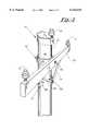
- FIG. 1is a perspective view illustrating a plurality of utility pole clamps 10 of the present invention secured to a utility pole 12 for fixedly receiving a top-mount insulator 14, a side-mount insulator 16, an eye-bolt 18, and ground cluster 90, in accordance with one broad aspect or feature of the present invention;
- FIG. 2is a perspective view illustrating a plurality of utility pole clamps 10 of the present invention secured to a utility pole 12 for mounting a cross arm member 22 and complementary brace members 24, 26 in accordance with yet another broad aspect of the present invention;
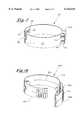
- FIG. 3is a perspective view of the utility pole clamp 10 shown in FIGS. 1 and 2 provided in accordance with a first preferred embodiment of the present invention
- FIG. 4is a perspective view of a utility pole clamp 20 provided in accordance with a second preferred embodiment of the present invention.
- FIG. 5is a perspective view of a utility pole clamp 30 provided in accordance with a third preferred embodiment of the present invention.
- FIG. 6is a perspective view of a utility pole clamp 40 provided in accordance with a fourth preferred embodiment of the present invention.
- FIG. 7is a perspective view of a utility pole clamp 50 provided in accordance with a fifth preferred embodiment of the present invention.
- FIG. 8is a perspective view of a utility pole clamp 60 provided in accordance with a sixth preferred embodiment of the present invention.
- FIGS. 1 and 2illustrate a plurality of utility pole clamps 10 provided in accordance with a first preferred embodiment of the present invention applied to a common utility pole 12.
- the upper utility pole clamp 10has a top-mount insulator 14 coupled thereto for supporting an upper cable 28
- the middle utility pole clamp 10has an eye-bolt 18 coupled thereto for attachment to a guy-wire 32
- the lower utility pole clamp 10has a side-mount insulator 16 coupled thereto for supporting a lower cable 34.
- FIG. 1illustrates the versatility of the present invention.
- FIG. 2shows the middle utility pole clamp 10 having a cross arm member 22 coupled thereto via a low profile bolt 36 for supporting a pair of top-mount insulators 14 laterally away from the utility pole 12, wherein the lower utility pole clamp 10 has first and second brace members 24, 26 coupled thereto via a low profile bolt 38 for supporting the cross arm member 22.
- the utility pole clamps provided in accordance with the present inventionprovide a light weight, versatile, safe, and economical alternative to the through-bolt fastening mechanisms typically employed in prior art utility pole applications.
- each utility pole clamp 10 of the first preferred embodimentincludes a band member 42, a primary locking mechanism comprising an over-center latch 44 hingedly attached to the band member 42, and a mounting block 46.
- the band member 42may be constructed from any number of generally conductive materials, including but not limited to heat treated steel, stainless steel, carbon reinforced plastic, or plastic having embedded conductive elements such as copper fiber.
- the band member 42includes a plurality of engagement grooves 48 disposed a predetermined distance from the over-center latch 44. The engagement grooves 48 are generally parallel to one another and provide a variety of purchase points for the over-center latch 44.
- the over-center latch 44includes an inner latch member 52 hingedly coupled to an outer latch member 54, wherein the outer latch member 54 includes an engagement lip 56 capable of being received within any of the engagement grooves 48 of the band member 42.
- the inner latch member 52is hingedly coupled to the band member 42 such that the over-center latch 44 may be quickly and easily manipulated to position the engagement lip 56 into a selected one of the engagement grooves 48.
- the over-center latch 44may thereafter be closed to secure the band member 42 on a utility pole by manipulating the inner and outer latch members 52, 54 in reverse fashion such that they reside in a generally flush and mating relationship against the band member 42.
- the over-center latch 44is tensioned such that it is capable of resiliently biasing the band member 42 against a utility pole with sufficient force to maintain the utility pole clamp 10 in a fixed vertical position under heavy loading conditions.
- the over-center latch 44provides a generally spring-loaded coupling such that the utility pole clamp 10 may readily flex to accommodate any expansion and/or contraction experienced by the utility pole.
- any of a variety of supplemental locking mechanismsmay be provided.
- a secondary locking mechanismcomprising a tab member 58 extending outwardly from the band member 42, a complementary aperture (not shown) formed in the inner latch member 52, and a complementary aperture 62 formed in the outer latch member 54.
- the tab member 58is designed to extend through the complementary aperture (not shown) of the inner latch member 52 and the complementary aperture 62 of the outer latch member 54 when the over-center latch 44 is in the fully closed position shown in FIGS. 1 and 2.
- a hole 64is further provided in the tab member 58 for receiving any type of lock or other obstruction device such that the over-center latch 44 will be locked or otherwise maintained in the closed position.
- a tertiary locking mechanismmay be further provided comprising a first detent member 66, a second detent member (not shown) disposed opposite the first detent member 66, a first engagement lip 68 for cooperating with the first detent member 66, and a second engagement lip 72 for cooperating with the second detent member (not shown).
- the first detent member 66 and the second detent member (not shown)are respectively formed along the upper and lower edges of the band member 42 proximate a first end thereof and comprise generally triangular notches capable of sliding through and past the first and second engagement lips 68, 72, respectively, during the closing of the over-center latch 44.
- a flex aperture 74may be formed in the band member 42 in between the first detent member 66 and the second detent member (not shown) to define an upper member 76 and a lower arm member 78.
- the flex aperture 74is dimensioned such that the upper and lower arm members 76, 78 may yield or bend slightly during the closure of the over-center latch 44 to accommodate the passage of the first detent member 66 through and past the first engagement lip 68 and the passage of the second detent member (not shown) through and past the second engagement lip 72.
- first detent member 66 and the second detent member(not shown) is such that they will not pass back through the first and second engagement lips 68, 72 except when a lineman intentionally biases the upper and lower arm members 76, 78 toward one another. This advantageously serves as yet another line of defense in securing the band member 42 to a utility pole.
- the mounting block 46comprises a generally rectangular article disposed along the inner surface of the band member 42.
- the mounting block 46may be constructed from any variety of rigid and durable materials, including but not limited to metal and carbon reinforced plastic.
- the mounting block 46is equipped with an upper receiving aperture 82 and a side receiving aperture (not shown) each having a threaded interior for threadably receiving various threaded utility pole fixtures.
- such fixturesmay include, but are not necessarily limited to, the top-mount insulator 14, the side-mount insulator 16, the eye-bolt 18, and the low profile bolts 36, 38.
- the mounting block 46may be fixed along the inner surface of the band member 42 by crimping portions of the upper and lower edges to envelope the top and bottom of the outermost edge of the mounting block 46 such as at 84.
- a low profile bolt 86may be provided through an aperture formed in the band member 42 for threaded receipt in the side receiving aperture (not shown) of the mounting block 46.
- the utility pole clamp 10 of the present inventionis configured such that, when secured to the utility pole 12, the mounting block 46 is disposed generally opposite from the over-center latch 44.
- the primary reason that the utility pole clamp 10 will remain at the same approximate vertical position on the utility pole 12 when fully loaded, i.e. under the weight of the upper cable 28, the lower cable 34, the guy-wire 32, the cross arm member 22, and/or the brace members 24, 26,is due to the resultant torque acting upon the band member 42.
- low profile bolt and/or screw members 88may be provided through the band member 42 which extend a nominal distance into the utility pole 12.
- such low profile bolt and/or screw members 88may also advantageously double as an attachment for a ground cluster, such as by coupling a ground wire 90 between the lower and middle utility pole clamps and the guy-wire 32 and/or earth ground wire. It may also advantageously be double or an attachment for single point grounding.
- the feature of single point groundingforms an important aspect of the present invention in that a conductive line or jumper may connect to a utility pole clamp 10 located below the lineman such that if a live wire or line 28 becomes energized, energy will be safely dissipated past the lineman to neutral wire or earth ground such as through a jumper from a conductive line or ground wire 90 to the clamp.
- FIG. 4shown is a utility pole clamp 20 provided in accordance with a second preferred embodiment of the present invention.
- the utility pole clamp 20has the same basic configuration as the utility pole clamp 20 illustrated in FIG. 3, including a band member 42 having a plurality of engagement grooves 48, a primary locking mechanism comprising an over-center latch 44 hingedly attached to the band member 42, and a mounting block 46 for fixedly coupling any of a variety of utility pole fixtures to the band member 42.
- the over-center latch 44 and mounting block 46are essentially identical in construction and function as that shown in FIG. 3.
- the band member 42is constructed to include a plurality of teeth members shown generally at 60 extending generally inward from the inner surface of the band member 42.
- the teeth members 53serve to penetrate the exterior surface of a utility pole when the utility pole clamp 20 is in use so as to fortify the vertical stability of the utility pole clamp 20, further protecting against potential slippage during heavy loading conditions.
- the teeth members 53furthermore provide a strain relief function by increasing the overall friction between the band member 42 and the pole 12 so as to lessen the degree of stress exerted upon the latch 44. They also assure positive contact between the pole and the clamp for facilitating increased electrical contact.
- FIG. 5represents a utility pole clamp 30 of a third preferred embodiment of the present invention.
- the utility pole clamp 30comprises a band member 42 having an upper row of engagement grooves 48a and a lower row of engagement grooves 48b, a primary locking mechanism comprising an over-center latch 44 hingedly attached to the band member 42, and a mounting block 46 for fixedly coupling any of a variety of utility pole fixtures to the band member 42.
- the over-center latch 44similarly includes an inner latch member 52 and an outer latch member 54.
- the outer latch member 54is hingedly attached to the band member 42 while the inner latch member 52 is formed to include an upper engagement lip 70 and a lower engagement lip (not shown) for cooperating with the upper and lower engagement grooves 48a, 48b, respectively.
- the over-center latch 44 of this embodimentnonetheless remains easy to operate such that the band member 42 may be quickly and easily secured about a utility pole. More specifically, this task is accomplished by first manipulating the inner and outer latch members 52, 54 such that the upper engagement lip 70 and the lower engagement lip (not shown) are disposed within a selected pair of vertically adjacent engagement grooves 48a, 48b. Thereafter, the inner and outer latch members 52, 54 are forced into a flush and mating relationship against the band member 42 such that the band member 42 is resiliently biased against the utility pole with sufficient force to maintain the utility pole clamp 30 in a fixed vertical position under heavy loading conditions.
- the over-center latch 44forms an important feature of the present invention in that it provides a compression-type coupling having a generally spring-loaded characteristic which allows the utility pole clamp 30 to flex and thus accommodate the expansion and/or contraction of the utility pole over time.
- the fact that the over-center latch 44 is in compressionis particularly advantageous because the latch 44 is therefore capable of absorbing substantially all of the force associated with the circumferential tension present while fastened about a utility pole, and is not limited by the strength of insertion tabs.
- Another significant feature of the utility pole clamp 30resides in the formation of the upper engagement grooves 48a, 48b.
- the upper and lower engagement grooves 48a, 48bincrease the overall tearout strength of the band 42 by minimizing the strain experienced by the band 42 as a result of the upper engagement lip 70 and the lower engagement lip (not shown).
- the upper and lower engagement grooves 48a, 48beach accept one half of the total strain experienced by the band 42, with one quarter of the total strain being directed at each end of the upper engagement groove 48a and one quarter of the total strain being directed at each end of the lower engagement groove 48b. Additional or multiple engagement grooves may be provided.
- a secondary locking mechanismcomprising a tab member 80 extending outwardly from the inner latch member 52 and a complementary aperture 100 formed in the outer latch member 54.
- the tab member 80is designed to extend through the complementary aperture 100 of the outer latch member 54 when the over-center latch 44 is in a fully closed position.
- the tab member 80may further include a hole 102 for receiving any of a variety of locks or other obstruction devices such that the over-center latch 44 may be locked or otherwise secured while in the closed position.
- FIG. 6illustrates a utility pole clamp 40 provided in accordance with a fourth preferred embodiment of the present invention.
- the utility pole clamp 40has the same basic configuration as that shown in FIG. 5, including a band member 42 having an upper row of engagement grooves 48a and a lower row of engagement grooves 48b, a primary locking mechanism comprising an over-center latch 44 hingedly attached to the band member 42, and a mounting block 46 for fixedly coupling any of a variety of utility pole fixtures to the band member 42.
- the over-center latch 44is formed as an integral extension of the band member 42. More specifically, the outer latch member 54 is hingedly coupled to the band member 42 via a first living hinge 104 and the inner and outer latch members 52, 54 are coupled together via a second living hinge 106.
- the over-center latch 44performs in the same fashion as described above, with the first and second living hinges 104, 106 cooperating with the inner and outer latch members 52, 54 to provide a spring-loaded coupling which allows the utility pole clamp 40 to flex and thus accommodate the expansion and/or contraction of the utility pole over time.
- the utility pole clamp 50includes a band member 42 having a first flange member 108 and a second flange member 110, a primary locking mechanism comprising a pair of low profile bolts 112, 114 for securely mating the first and second flange members 108, 110, and a mounting block 46 for fixedly coupling any of a variety of utility pole fixtures to the band member 42.
- the flange members 108, 110may be dimensioned such that, when biased together with the low profile bolts 112, 114, they resiliently bias the band member 42 against a utility pole with sufficient force to maintain the utility pole clamp 50 in a fixed vertical position and, moreover, provide a generally spring-loaded coupling such that the utility pole clamp 50 may readily flex to accommodate any expansion and/or contraction experienced by the utility pole.
- FIG. 8shown is a utility pole clamp shown generally at 60A provided in accordance with a sixth preferred embodiment of the present invention.
- the utility pole clamp 60has the same basic configuration as that shown in FIG. 5, including a band member 42 having an upper row of engagement grooves 48a and a lower row of engagement grooves 48b, a primary locking mechanism comprising an over-center latch 44 hingedly attached to the band member 42, and a mounting block 46 for fixedly coupling any of a variety of utility pole fixtures to the band member 42.
- the main distinctionis that the band member 42 and over-center latch 44 are provided in a split configuration.
- the band member 42includes an upper band member 42a and a lower band member 42b divided by a cut-line 42c
- the over-center latch 44includes an upper outer latch member 54a and a lower outer latch member 54b divided by a cut-line 54c, and an upper inner latch member 52a and a lower inner latch member (not shown) divided by a cut-line (not shown).
- the band member 42is split into the upper band member 42a and the lower band member 42b in two separate areas, namely in between the upper and lower engagement grooves 48a, 48b and a span extending a predetermined distance from the hinged coupling with the over-center latch 44 towards the mounting block 46.
- the over-center latch 44 of the utility pole clamp 60Aperforms in the same fashion as described above with reference to FIG. 5, with the upper and lower outer latch members 54a, 54b and the upper and lower inner latch members 52a, (not shown) cooperating with the upper and lower engagement grooves 48a, 48b in a compression configuration which allows the utility pole clamp 60A to flex and thus accommodate the expansion and/or contraction of the utility pole over time.
- the advantage of the compression-type couplingonce again, is that the over-center latch 44 is capable of absorbing substantially all of the force associated with the circumferential tension of the utility pole clamp and not limited by the strength of the tabs.
- the split configuration of the utility pole clamp 60Aadvantageously allows the upper and lower portions of the band member 42 to be tightened individually such that the utility pole clamp 60A is readily capable of accommodating surface irregularities on the utility pole which, by way of example and not limitation, may include knots formed in the utility pole or the taper of the utility pole.
- the utility pole clamp 60Ais capable of accommodating such surface irregularities due to the fact that the upper and lower band members 42a, 42b, the upper and lower outer latch a members 54a, 54b, and the upper and lower inner latch members 52a, (not shown) are provided such that the upper and lower portions of the utility pole clamp 60A may be selectively adjusted to have different circumferences.
- the upper portion of the utility pole clamp 60Amay be adjusted to be tighter, i.e. having a smaller circumference, than the lower portion of the utility pole clamp 60A such that the upper portion thereof is adequately secured about the utility pole. This ensures that the utility pole clamp 60A will be affixed to the utility pole in the tightest and most secure possible fashion, thereby increasing the overall safety and reliability of the utility pole clamp 60A.
- the present inventionsolves the various drawbacks found in the prior art by providing an improved fastening mechanism for attaching power transmission and related fixtures to utility poles.
- the improved fastening mechanismcomprises a utility pole clamp which does not require the formation of through bores and is light weight and easy to work with such that a lineman can readily perform the required operations in quick fashion with minimal physical exertion.
- the utility pole clamp of the present inventionreduces the overall number of parts which a lineman must handle while at the top of the utility pole, thereby minimizing the likelihood of fumbling or dropping parts during installation and/or repair operations.
- the utility pole clamp set forth abovemay also provide single point grounding or a ground cluster when employed, thereby improving safety of the lineman during installation and service operations.
- the aforementioned utility pole clampfurthermore advantageously dissipates the electricity from a lightning strike away from the center of the utility pole so as to protect the structural integrity of the utility pole and related fixtures.
- the utility pole clamp of the present inventionis low profile relative to the utility pole so as to minimize the risk of snagging the lineman's clothing and/or rubber insulating covers.
- the utility pole clamp of the present inventionis furthermore capable of flexing to accommodate the contraction and expansion of utility poles without loosening while at the same time providing a sturdy attachment such that the fixtures will not shift or slide down the utility pole over time.
- FIGS. 3-8may be combined, modified, and/or simplified in any number of different fashions without departing from the scope of the present invention.
- mounting blocksare illustrated in each of the foregoing embodiments, it is to be readily understood that the mounting blocks may be formed in any number of different configurations and shapes or, alternatively, the mounting blocks may be omitted altogether depending upon the application.
Landscapes
- Engineering & Computer Science (AREA)
- Architecture (AREA)
- Civil Engineering (AREA)
- Structural Engineering (AREA)
- Clamps And Clips (AREA)
Abstract
Description
The present application relates to that certain Provisional Application Serial No. 60/051,395 filed Jul. 1, 1997 of Michael D. Trost and Scot M. Brinkman, entitled "UTILITY POLE CLAMP".
I. Field of the Invention
The present invention relates generally to utility poles. More particularly, the present invention relates to a multi-purpose utility pole clamp capable of supporting overhead lines or cables, including transmission lines for electrical signals such as electrical fencing and other applications, and adhering any of a variety of fixtures to the utility pole without the need for a traditional through-bolt fastening mechanism.
II. Discussion of the Prior Art
For years, utility poles have been used to carry overhead lines or cables for supporting power generation, transmission and distribution lines, telephone lines and more recently cable television lines. The task of supporting these wires and/or cables is typically accomplished through the use of a variety of different fixtures, including insulators for providing electrical isolation between the wires/cables and the utility pole, eye bolts for attaching guy wires to the utility pole, cross arm members for supporting the insulators and wires laterally away from the utility pole, and brace members for providing structural support to the cross arm members. Fixtures such as these are commonly adhered to the utility pole via a traditional through-bolt fastening mechanism characterized by passing an elongated bolt through a bore formed in the utility pole for attachment to mating nut member. While this fastening mechanism is generally effective in supporting such fixtures, a multitude of substantial drawbacks nonetheless exist which consequently precipitate the need for the present invention.
Several prominent drawbacks with through bolt fastening mechanisms relate to the need for bores extending through the utility pole for receiving the elongated bolts. A first drawback related to the through bores is that they are disadvantageously expensive in terms of both the labor and time required to create them. Moreover, in many instances the bores must be created while the lineman is at the top of the utility pole which, as will be appreciated, presents a substantial challenge to the lineman in manipulating the drilling devices used to fashion such bores. A still further drawback with through bores is that they allow moisture to migrate into the interior of the utility pole, thereby increasing the likelihood of premature decay and deterioration.
Another drawback with through-bolt fastening mechanisms are quite cumbersome and time consuming to implement. This stems, in large part, from the fact that utility poles typically vary in diameter such that a lineman must carry a wide variety of bolt sizes and related hardware at all times to handle any installation and/or repair task. Requiring the lineman to carry such a wide variety of hardware at all times can be physically burdensome due to the weight of such articles, especially during instances when the lineman must walk long distances to remote work sites which are inaccessible except by foot. In similar fashion, the weight of such hardware may also present difficulties for the lineman while ascending and descending the utility pole to perform installation and/or repair operations.
Further problems stem from the fact that the lineman must manually handle and negotiate a multitude of different components while disposed on the top of the utility pole in order to install or repair such through-bolt fastening mechanisms. For example, handling the multitude of parts requires a great deal of manual dexterity on the part of the lineman such that an increased likelihood exists of having the lineman fumble or drop parts during such installation and/or repair operations. Moreover, it is typically quite time consuming and laborious to assemble the bolt hardware during such operations. This translates into increased labor costs, an increased likelihood of having the lineman suffer from chronic fatigue and/or carpal tunnel syndrome, and an increased likelihood of overexposing the lineman to adverse and potentially dangerous weather conditions when conducting repair operations in emergency situations.
Still other problems relate to the physical arrangement of the bolts while coupled to a utility pole. One such drawback is that the bolts extend through the center of the utility pole when installed. The metallic nature of the bolts creates a line of conductivity through the utility pole such that, in the case of a lightning strike, the resulting electrical charge is concentrated within the center of the pole. As will be appreciated by those skilled in the art, directing the electrical charge of a lightning strike into the center of the utility pole creates an increased likelihood of having the utility pole burst, split, or become otherwise structurally damaged. This jeopardizes not only the structural integrity of the utility pole, but also the structural integrity of the various fixtures as attached to the poles. In either event, an increased risk arises of having downed utility poles and/or wires which consequently raises concerns of safety and high repair and/or replacement costs.
Another related drawback stems from that fact that the bolt and nut arrangements typically extend well past the circumference of the utility pole when fully installed. This can be problematic from the standpoint of having the clothes of the lineman snag on the bolts or nuts while working on the utility pole which, at the very least, may impede the actions of the lineman. The outwardly extending bolts members may also present snagging problems during the installation of rubber insulating covers which are typically employed in conjunction with utility poles, thereby increasing the time and energy required to perform such operations. Bolts present the additional danger of possibly piercing the insulation barrier and expose the lineman or other technician to the dangers of the electrical energy being transmitted by the carrier.
A still further drawback stems from the fact that utility poles typically experience a fair degree of contraction and expansion due to changes in temperature, humidity, age, etc. . . . More specifically, the bolt and nut arrangement of through-bolt fastening mechanisms tend to loosen over time due to such expansion and contraction of the utility poles. This tendency for loosening requires a lineman to visit each utility pole on a regular basis for the purpose of re-tightening such components, thereby increasing the labor costs associated with maintaining the utility poles. Moreover, such loosening creates the possibility of having the various fixtures becoming detached from the utility poles, thereby raising the specter of having downed power, television, and cable lines.
A need therefore exists for an improved fastening mechanism for attaching power transmission and related fixtures to utility poles. The improved fastening mechanism should eliminate the need for through bores in the utility poles and be light weight and easy to work with such that a lineman can readily perform the required operations in quick fashion with minimal physical exertion. The improved fastening mechanism should reduce the overall number of parts which a lineman must handle while at the top of the utility pole so as to minimize the chance of fumbling or dropping parts during installation and/or repair operations. Furthermore, the improved fastening mechanism should dissipate the electricity from a lightning strike away from the center of the utility pole so as to protect the structural integrity of the utility pole and the various fixtures. The improved fastening mechanism should also be low profile relative to the circumference of the utility pole so as to minimize the risk of snagging or damaging the lineman's protective clothing and/or rubber insulating covers.
Moreover, the improved fastening mechanism should be capable of flexing to accommodate the contraction and expansion of utility poles without loosening while at the same time providing a sturdy attachment such that the fixtures will not shift or slide down the utility pole over time.
It is accordingly a principal object of the present invention to provide an improved fastening mechanism for attaching power transmission and related fixtures to utility poles which does not require the formation of through bores and which is light weight and easy to work with such that a lineman can readily perform the required operations in quick fashion with minimal physical exertion.
It is a further object of the present invention to provide an improved fastening mechanism for attaching power lines and related fixtures to utility poles which reduces the overall number of parts which a lineman must handle while at the top of the utility pole so as to minimize the chance of fumbling or dropping parts during installation and/or repair operations.
It is a still further object of the present invention to provide an improved fastening mechanism for attaching power lines and related fixtures to utility poles which dissipates the electricity from a lightning strike away from the center of the utility pole so as to protect the structural integrity of the utility pole and the various fixtures.
It is yet another object of the present invention to provide an improved fastening mechanism for attaching power lines and related fixtures to utility poles which is low profile relative to the circumference of the utility pole so as to minimize the risk of snagging the lineman's protective clothing and/or rubber insulating covers.
It is a further object of the present invention to provide an improved fastening mechanism for attaching power lines and related fixtures to utility poles which is capable of flexing to accommodate the various contraction and expansion of utility poles without loosening while at the same time providing a sturdy attachment such that the fixtures will not shift or slide down the utility pole over time.
In accordance with the present invention, the foregoing objects and advantages are achieved by providing a utility pole clamp capable of being fixedly yet flexibly secured around the circumference of a utility pole for attaching any of a variety of fixtures to the utility pole, including but not limited to insulators, eye bolts, cross arm members, and brace members. The utility pole clamp of the present invention includes an electrically conductive band member for placement about the circumference of the utility pole, a locking mechanism for resiliently biasing the band member against the utility pole to thereby fixedly yet flexibly secure the band member to the utility pole, and in certain applications, a mounting block having at least one receiving aperture for rigidly coupling any of a variety of fixtures to the band member.
The band member is light weight and preferably constructed from sheet metal, such as stainless steel, having sufficient thickness and tear-out strength to withstand heavy loading when disposed on the utility pole. The band member may alternately be constructed from carbon reinforced plastic and/or plastic having internally disposed copper or metallic inserts, so long as the band member is generally electrically conductive. In most applications, the electrical conductivity of the band member serves to dissipate stray voltages caused by improper grounding, unbalanced loading, or line loss or a line inadvertently becoming energized during repair. In these applications, a ground cluster may be achieved, or alternatively a single point grounding may be facilitated. Moreover, the band member effectively creates a conductive path about the periphery of the utility pole such that the electrical energy from a lightning strike will be dissipated around the entire outer surface of the utility pole rather than through the center of the pole as with a through-bolt fastening mechanism, thereby minimizing the likelihood of structural damage to the pole and/or fixtures during such conditions. The band member may also be provided with teeth members for gripping into the surface of the utility pole when secured to the utility pole, and to provide additional positive contact with the pole for grounding purposes.
The locking mechanism may be formed as a separate member or as an integral portion of the band member. In a preferred embodiment, the locking mechanism comprises an over-center latch capable of engaging with complimentary grooves formed in the band member to thereby fixedly and flexibly secure the band member to the utility pole. Alternate and/or supplemental locking mechanisms may also be provided, including but not limited to an interlocking detent arrangement, a mating tab/aperture arrangement, and a cooperating flange/bolt arrangement. These locking mechanisms are advantageously simple and easy to operate such that a lineman may secure the utility pole clamp in quick fashion with minimal physical exertion.
The receiving apertures within the mounting block are preferably formed as industry standard threaded bores capable of accepting any number of industry standard threaded fixtures, i.e. low profile bolt members, eye bolts, and insulators, such that the lineman is not required to drill or form any bores through the utility pole for the purposes of attaching such fixtures. This provides improved versatility over the through-bolt fastening mechanism by allowing a lineman to quickly and easily install and remove various fixtures into and from the receiving apertures. This also reduces the overall number of parts which a lineman must handle while at the top of the utility pole so as to minimize the chance of fumbling or dropping parts during installation and/or repair operations.
The utility pole clamp of the present invention is advantageously capable of securing any of a variety of utility pole fixtures in a low profile fashion so as to minimize the risk of snagging or damaging the lineman's protective clothing and/or interfering with the installation of rubber insulating covers. Moreover, the utility pole clamp is advantageously capable of flexing to accommodate the contraction and expansion of utility poles while providing a sturdy attachment such that the fixtures will not shift or slide down the utility pole over time.
The foregoing features and advantages of the present invention will be readily apparent to those skilled in the art from a review of the following detailed description of the preferred embodiment in conjunction with the accompanying drawings and claims.
FIG. 1 is a perspective view illustrating a plurality of utility pole clamps 10 of the present invention secured to autility pole 12 for fixedly receiving a top-mount insulator 14, a side-mount insulator 16, an eye-bolt 18, andground cluster 90, in accordance with one broad aspect or feature of the present invention;
FIG. 2 is a perspective view illustrating a plurality of utility pole clamps 10 of the present invention secured to autility pole 12 for mounting across arm member 22 andcomplementary brace members
FIG. 3 is a perspective view of theutility pole clamp 10 shown in FIGS. 1 and 2 provided in accordance with a first preferred embodiment of the present invention;
FIG. 4 is a perspective view of autility pole clamp 20 provided in accordance with a second preferred embodiment of the present invention;
FIG. 5 is a perspective view of autility pole clamp 30 provided in accordance with a third preferred embodiment of the present invention;
FIG. 6 is a perspective view of autility pole clamp 40 provided in accordance with a fourth preferred embodiment of the present invention;
FIG. 7 is a perspective view of autility pole clamp 50 provided in accordance with a fifth preferred embodiment of the present invention; and
FIG. 8 is a perspective view of autility pole clamp 60 provided in accordance with a sixth preferred embodiment of the present invention.
FIGS. 1 and 2 illustrate a plurality of utility pole clamps 10 provided in accordance with a first preferred embodiment of the present invention applied to acommon utility pole 12. In FIG. 1, the upperutility pole clamp 10 has a top-mount insulator 14 coupled thereto for supporting anupper cable 28, the middleutility pole clamp 10 has an eye-bolt 18 coupled thereto for attachment to a guy-wire 32, and the lowerutility pole clamp 10 has a side-mount insulator 16 coupled thereto for supporting alower cable 34. To further illustrate the versatility of the present invention, FIG. 2 shows the middleutility pole clamp 10 having across arm member 22 coupled thereto via alow profile bolt 36 for supporting a pair of top-mount insulators 14 laterally away from theutility pole 12, wherein the lowerutility pole clamp 10 has first andsecond brace members low profile bolt 38 for supporting thecross arm member 22. As will be set forth in greater detail below, the utility pole clamps provided in accordance with the present invention provide a light weight, versatile, safe, and economical alternative to the through-bolt fastening mechanisms typically employed in prior art utility pole applications.
With reference to FIG. 3, eachutility pole clamp 10 of the first preferred embodiment includes aband member 42, a primary locking mechanism comprising anover-center latch 44 hingedly attached to theband member 42, and a mountingblock 46. Theband member 42 may be constructed from any number of generally conductive materials, including but not limited to heat treated steel, stainless steel, carbon reinforced plastic, or plastic having embedded conductive elements such as copper fiber. Theband member 42 includes a plurality ofengagement grooves 48 disposed a predetermined distance from theover-center latch 44. Theengagement grooves 48 are generally parallel to one another and provide a variety of purchase points for theover-center latch 44. More specifically, theover-center latch 44 includes aninner latch member 52 hingedly coupled to anouter latch member 54, wherein theouter latch member 54 includes anengagement lip 56 capable of being received within any of theengagement grooves 48 of theband member 42. Theinner latch member 52 is hingedly coupled to theband member 42 such that theover-center latch 44 may be quickly and easily manipulated to position theengagement lip 56 into a selected one of theengagement grooves 48. Theover-center latch 44 may thereafter be closed to secure theband member 42 on a utility pole by manipulating the inner andouter latch members band member 42.
In an important aspect of the present invention, theover-center latch 44 is tensioned such that it is capable of resiliently biasing theband member 42 against a utility pole with sufficient force to maintain theutility pole clamp 10 in a fixed vertical position under heavy loading conditions. In yet another significant aspect, theover-center latch 44 provides a generally spring-loaded coupling such that theutility pole clamp 10 may readily flex to accommodate any expansion and/or contraction experienced by the utility pole. As further assurance against having theband member 42 loosen or slip from its position on a utility pole, any of a variety of supplemental locking mechanisms may be provided. For example, in the preferred embodiment a secondary locking mechanism is shown comprising atab member 58 extending outwardly from theband member 42, a complementary aperture (not shown) formed in theinner latch member 52, and acomplementary aperture 62 formed in theouter latch member 54. In this arrangement, thetab member 58 is designed to extend through the complementary aperture (not shown) of theinner latch member 52 and thecomplementary aperture 62 of theouter latch member 54 when theover-center latch 44 is in the fully closed position shown in FIGS. 1 and 2. Ahole 64 is further provided in thetab member 58 for receiving any type of lock or other obstruction device such that theover-center latch 44 will be locked or otherwise maintained in the closed position.
A tertiary locking mechanism may be further provided comprising afirst detent member 66, a second detent member (not shown) disposed opposite thefirst detent member 66, afirst engagement lip 68 for cooperating with thefirst detent member 66, and asecond engagement lip 72 for cooperating with the second detent member (not shown). Thefirst detent member 66 and the second detent member (not shown) are respectively formed along the upper and lower edges of theband member 42 proximate a first end thereof and comprise generally triangular notches capable of sliding through and past the first andsecond engagement lips over-center latch 44. To facilitate this engagement, aflex aperture 74 may be formed in theband member 42 in between thefirst detent member 66 and the second detent member (not shown) to define anupper member 76 and alower arm member 78. Theflex aperture 74 is dimensioned such that the upper andlower arm members over-center latch 44 to accommodate the passage of thefirst detent member 66 through and past thefirst engagement lip 68 and the passage of the second detent member (not shown) through and past thesecond engagement lip 72. In an important aspect, the triangular nature of thefirst detent member 66 and the second detent member (not shown) is such that they will not pass back through the first andsecond engagement lips lower arm members band member 42 to a utility pole.
The mountingblock 46 comprises a generally rectangular article disposed along the inner surface of theband member 42. The mountingblock 46 may be constructed from any variety of rigid and durable materials, including but not limited to metal and carbon reinforced plastic. In the preferred embodiment, the mountingblock 46 is equipped with anupper receiving aperture 82 and a side receiving aperture (not shown) each having a threaded interior for threadably receiving various threaded utility pole fixtures. With brief reference to FIGS. 1 and 2, such fixtures may include, but are not necessarily limited to, the top-mount insulator 14, the side-mount insulator 16, the eye-bolt 18, and thelow profile bolts block 46 may be fixed along the inner surface of theband member 42 by crimping portions of the upper and lower edges to envelope the top and bottom of the outermost edge of the mountingblock 46 such as at 84. As alternative or supplemental fixing means, alow profile bolt 86 may be provided through an aperture formed in theband member 42 for threaded receipt in the side receiving aperture (not shown) of the mountingblock 46.
As illustrated in FIGS. 1 and 2, theutility pole clamp 10 of the present invention is configured such that, when secured to theutility pole 12, the mountingblock 46 is disposed generally opposite from theover-center latch 44. The primary reason that theutility pole clamp 10 will remain at the same approximate vertical position on theutility pole 12 when fully loaded, i.e. under the weight of theupper cable 28, thelower cable 34, the guy-wire 32, thecross arm member 22, and/or thebrace members band member 42. For further assurance against vertical slippage, low profile bolt and/orscrew members 88 may be provided through theband member 42 which extend a nominal distance into theutility pole 12. In a preferred embodiment, such low profile bolt and/orscrew members 88 may also advantageously double as an attachment for a ground cluster, such as by coupling aground wire 90 between the lower and middle utility pole clamps and the guy-wire 32 and/or earth ground wire. It may also advantageously be double or an attachment for single point grounding. The feature of single point grounding forms an important aspect of the present invention in that a conductive line or jumper may connect to autility pole clamp 10 located below the lineman such that if a live wire orline 28 becomes energized, energy will be safely dissipated past the lineman to neutral wire or earth ground such as through a jumper from a conductive line orground wire 90 to the clamp.
Turning now to FIG. 4, shown is autility pole clamp 20 provided in accordance with a second preferred embodiment of the present invention. Theutility pole clamp 20 has the same basic configuration as theutility pole clamp 20 illustrated in FIG. 3, including aband member 42 having a plurality ofengagement grooves 48, a primary locking mechanism comprising anover-center latch 44 hingedly attached to theband member 42, and a mountingblock 46 for fixedly coupling any of a variety of utility pole fixtures to theband member 42. Theover-center latch 44 and mountingblock 46 are essentially identical in construction and function as that shown in FIG. 3. As a result, these features will not be described further other than to point out that this embodiment does not include a secondary locking mechanism such that the inner andouter latch members over-center latch 44 do not include any complementary apertures for receiving a tab member as described above. Theband member 42 is constructed to include a plurality of teeth members shown generally at 60 extending generally inward from the inner surface of theband member 42. As will be appreciated, the teeth members 53 serve to penetrate the exterior surface of a utility pole when theutility pole clamp 20 is in use so as to fortify the vertical stability of theutility pole clamp 20, further protecting against potential slippage during heavy loading conditions. The teeth members 53 furthermore provide a strain relief function by increasing the overall friction between theband member 42 and thepole 12 so as to lessen the degree of stress exerted upon thelatch 44. They also assure positive contact between the pole and the clamp for facilitating increased electrical contact.
FIG. 5 represents autility pole clamp 30 of a third preferred embodiment of the present invention. Theutility pole clamp 30 comprises aband member 42 having an upper row ofengagement grooves 48a and a lower row ofengagement grooves 48b, a primary locking mechanism comprising anover-center latch 44 hingedly attached to theband member 42, and a mountingblock 46 for fixedly coupling any of a variety of utility pole fixtures to theband member 42. Theover-center latch 44 similarly includes aninner latch member 52 and anouter latch member 54. However, in contra-distinction to the embodiments shown in FIGS. 3 and 4, theouter latch member 54 is hingedly attached to theband member 42 while theinner latch member 52 is formed to include anupper engagement lip 70 and a lower engagement lip (not shown) for cooperating with the upper andlower engagement grooves over-center latch 44 of this embodiment nonetheless remains easy to operate such that theband member 42 may be quickly and easily secured about a utility pole. More specifically, this task is accomplished by first manipulating the inner andouter latch members upper engagement lip 70 and the lower engagement lip (not shown) are disposed within a selected pair of verticallyadjacent engagement grooves outer latch members band member 42 such that theband member 42 is resiliently biased against the utility pole with sufficient force to maintain theutility pole clamp 30 in a fixed vertical position under heavy loading conditions.
Theover-center latch 44 forms an important feature of the present invention in that it provides a compression-type coupling having a generally spring-loaded characteristic which allows theutility pole clamp 30 to flex and thus accommodate the expansion and/or contraction of the utility pole over time. The fact that theover-center latch 44 is in compression is particularly advantageous because thelatch 44 is therefore capable of absorbing substantially all of the force associated with the circumferential tension present while fastened about a utility pole, and is not limited by the strength of insertion tabs. Another significant feature of theutility pole clamp 30 resides in the formation of theupper engagement grooves lower engagement grooves band 42 by minimizing the strain experienced by theband 42 as a result of theupper engagement lip 70 and the lower engagement lip (not shown). The upper andlower engagement grooves band 42, with one quarter of the total strain being directed at each end of theupper engagement groove 48a and one quarter of the total strain being directed at each end of thelower engagement groove 48b. Additional or multiple engagement grooves may be provided.
While theover-center latch 44 is highly stable and secure when fully closed about a utility pole, this design may be further fortified by adding any number of supplemental locking mechanisms, such as a secondary locking mechanism comprising atab member 80 extending outwardly from theinner latch member 52 and acomplementary aperture 100 formed in theouter latch member 54. Thetab member 80 is designed to extend through thecomplementary aperture 100 of theouter latch member 54 when theover-center latch 44 is in a fully closed position. Thetab member 80 may further include ahole 102 for receiving any of a variety of locks or other obstruction devices such that theover-center latch 44 may be locked or otherwise secured while in the closed position.
FIG. 6 illustrates autility pole clamp 40 provided in accordance with a fourth preferred embodiment of the present invention. Theutility pole clamp 40 has the same basic configuration as that shown in FIG. 5, including aband member 42 having an upper row ofengagement grooves 48a and a lower row ofengagement grooves 48b, a primary locking mechanism comprising anover-center latch 44 hingedly attached to theband member 42, and a mountingblock 46 for fixedly coupling any of a variety of utility pole fixtures to theband member 42. The sole distinction is that theover-center latch 44 is formed as an integral extension of theband member 42. More specifically, theouter latch member 54 is hingedly coupled to theband member 42 via afirst living hinge 104 and the inner andouter latch members second living hinge 106. Notwithstanding this change, theover-center latch 44 performs in the same fashion as described above, with the first and second living hinges 104, 106 cooperating with the inner andouter latch members utility pole clamp 40 to flex and thus accommodate the expansion and/or contraction of the utility pole over time.
Turning now to FIG. 7, shown is autility pole clamp 50 provided in accordance with a fifth preferred embodiment of the present invention. Theutility pole clamp 50 includes aband member 42 having afirst flange member 108 and a second flange member 110, a primary locking mechanism comprising a pair oflow profile bolts second flange members 108, 110, and a mountingblock 46 for fixedly coupling any of a variety of utility pole fixtures to theband member 42. Theflange members 108, 110 may be dimensioned such that, when biased together with thelow profile bolts band member 42 against a utility pole with sufficient force to maintain theutility pole clamp 50 in a fixed vertical position and, moreover, provide a generally spring-loaded coupling such that theutility pole clamp 50 may readily flex to accommodate any expansion and/or contraction experienced by the utility pole.
Referring lastly to FIG. 8, shown is a utility pole clamp shown generally at 60A provided in accordance with a sixth preferred embodiment of the present invention. Theutility pole clamp 60 has the same basic configuration as that shown in FIG. 5, including aband member 42 having an upper row ofengagement grooves 48a and a lower row ofengagement grooves 48b, a primary locking mechanism comprising anover-center latch 44 hingedly attached to theband member 42, and a mountingblock 46 for fixedly coupling any of a variety of utility pole fixtures to theband member 42. The main distinction is that theband member 42 andover-center latch 44 are provided in a split configuration. More specifically, theband member 42 includes anupper band member 42a and alower band member 42b divided by a cut-line 42c, while theover-center latch 44 includes an upperouter latch member 54a and a lowerouter latch member 54b divided by a cut-line 54c, and an upper inner latch member 52a and a lower inner latch member (not shown) divided by a cut-line (not shown).
In a preferred embodiment, theband member 42 is split into theupper band member 42a and thelower band member 42b in two separate areas, namely in between the upper andlower engagement grooves over-center latch 44 towards the mountingblock 46. Theover-center latch 44 of the utility pole clamp 60A performs in the same fashion as described above with reference to FIG. 5, with the upper and lowerouter latch members lower engagement grooves over-center latch 44 is capable of absorbing substantially all of the force associated with the circumferential tension of the utility pole clamp and not limited by the strength of the tabs.
In an important aspect of the present invention, the split configuration of the utility pole clamp 60A advantageously allows the upper and lower portions of theband member 42 to be tightened individually such that the utility pole clamp 60A is readily capable of accommodating surface irregularities on the utility pole which, by way of example and not limitation, may include knots formed in the utility pole or the taper of the utility pole. As will be appreciated by those skilled in the art, the utility pole clamp 60A is capable of accommodating such surface irregularities due to the fact that the upper andlower band members members
In light of the foregoing, the present invention solves the various drawbacks found in the prior art by providing an improved fastening mechanism for attaching power transmission and related fixtures to utility poles. The improved fastening mechanism comprises a utility pole clamp which does not require the formation of through bores and is light weight and easy to work with such that a lineman can readily perform the required operations in quick fashion with minimal physical exertion. The utility pole clamp of the present invention reduces the overall number of parts which a lineman must handle while at the top of the utility pole, thereby minimizing the likelihood of fumbling or dropping parts during installation and/or repair operations. The utility pole clamp set forth above may also provide single point grounding or a ground cluster when employed, thereby improving safety of the lineman during installation and service operations. The aforementioned utility pole clamp furthermore advantageously dissipates the electricity from a lightning strike away from the center of the utility pole so as to protect the structural integrity of the utility pole and related fixtures. Moreover, the utility pole clamp of the present invention is low profile relative to the utility pole so as to minimize the risk of snagging the lineman's clothing and/or rubber insulating covers. The utility pole clamp of the present invention is furthermore capable of flexing to accommodate the contraction and expansion of utility poles without loosening while at the same time providing a sturdy attachment such that the fixtures will not shift or slide down the utility pole over time.
This invention has been described herein in considerable detail in order to comply with the Patent Statutes and to provide those skilled in the art with the information needed to apply the novel principles and to construct and use such specialized components as are required. However, it is to be understood that the invention can be carried out by specifically different equipment and devices, and that various modifications, both as to the equipment details and operating procedures, can be accomplished without departing from the scope of the invention itself.
In this regard, it is to be readily understood that the various teachings set forth above with reference to FIGS. 3-8 may be combined, modified, and/or simplified in any number of different fashions without departing from the scope of the present invention. For example, although mounting blocks are illustrated in each of the foregoing embodiments, it is to be readily understood that the mounting blocks may be formed in any number of different configurations and shapes or, alternatively, the mounting blocks may be omitted altogether depending upon the application.
Claims (1)
1. Fastening means for use in securing electrical power, communication and signal transmission lines and cables to a line supporting utility pole and comprising:
(a) an electrically conductive band member for circumferentially encircling said line supporting utility pole;
(b) said electrically conductive band member comprising an integral locking means for resilient biased engagement with and in tension about said line supporting utility pole so as to fixedly and flexibly secure said electrically conductive band member about the circumference of said line supporting utility pole;
(c) a mounting block means coupled to said electrically conductive band member having at least one receiving aperture formed therein for rigidly securing a transmission line or cable engaging fixture thereto;
(d) said electrically conductive band member is provided with radially inwardly extending pole engaging teeth;
(e) said locking means comprises an over-center latch;
(f) supplemental locking means are provided for maintaining said electrically conductive band member in position on said line supporting utility pole; and
(g) said supplemental locking means comprising interlocking detent-teeth.
Priority Applications (1)
| Application Number | Priority Date | Filing Date | Title |
|---|---|---|---|
| US09/070,193US6142434A (en) | 1997-07-01 | 1998-04-30 | Utility pole clamp |
Applications Claiming Priority (2)
| Application Number | Priority Date | Filing Date | Title |
|---|---|---|---|
| US5139597P | 1997-07-01 | 1997-07-01 | |
| US09/070,193US6142434A (en) | 1997-07-01 | 1998-04-30 | Utility pole clamp |
Publications (1)
| Publication Number | Publication Date |
|---|---|
| US6142434Atrue US6142434A (en) | 2000-11-07 |
Family
ID=26729367
Family Applications (1)
| Application Number | Title | Priority Date | Filing Date |
|---|---|---|---|
| US09/070,193Expired - Fee RelatedUS6142434A (en) | 1997-07-01 | 1998-04-30 | Utility pole clamp |
Country Status (1)
| Country | Link |
|---|---|
| US (1) | US6142434A (en) |
Cited By (176)
| Publication number | Priority date | Publication date | Assignee | Title |
|---|---|---|---|---|
| US6394228B1 (en)* | 2000-07-28 | 2002-05-28 | Kendall M. Stephens | Accessory for a fence post |
| US6453636B1 (en) | 2000-04-24 | 2002-09-24 | Charles D. Ritz | Method and apparatus for increasing the capacity and stability of a single-pole tower |
| US6520462B2 (en)* | 2001-03-16 | 2003-02-18 | American Electric Power Company, Inc. | Temporary arm support |
| US20030072683A1 (en)* | 1999-08-02 | 2003-04-17 | Emerald Biostructures, Inc. | Robot for mixing crystallization trial matrices |
| US6595477B2 (en) | 2001-09-25 | 2003-07-22 | Hubbell Incorporated | Mounting bracket for an insulator assembly |
| US20030176227A1 (en)* | 2000-11-17 | 2003-09-18 | David Czaja | Golf swing training apparatus |
| US6668498B2 (en) | 2000-12-13 | 2003-12-30 | Ritz Telecommunications, Inc. | System and method for supporting guyed towers having increased load capacity and stability |
| US20040020158A1 (en)* | 2002-08-02 | 2004-02-05 | Kopshever Michael J. | Tower apparatus |
| US20040084582A1 (en)* | 2002-07-08 | 2004-05-06 | Kralic John Frank | Utility pole cross-arm and associated pole-top hardware |
| FR2848031A1 (en)* | 2003-03-27 | 2004-06-04 | France Telecom | Fixing cap for overhead telecommunication cable suspension on ridge sheathing, has limiting device that limits charge/load releases cap with sliding motion along post under action of force exerted by cable on cap |
| US20040134155A1 (en)* | 2002-10-03 | 2004-07-15 | Lockwood James D. | System and method for strengthening tubular and round tower members |
| US20040148903A1 (en)* | 2000-04-24 | 2004-08-05 | Cash David W. | Method and apparatus for increasing the capacity and stability of a single-pole tower |
| US20040194402A1 (en)* | 2003-04-01 | 2004-10-07 | Payne Calvin J. | Tower monopole reinforcement |
| US6948290B2 (en) | 2000-12-13 | 2005-09-27 | Ritz Telecommunications, Inc. | System and method for increasing the load capacity and stability of guyed towers |
| US20050274070A1 (en)* | 2004-06-14 | 2005-12-15 | Steadman William D | Support arrangement |
| US20060180723A1 (en)* | 2005-02-01 | 2006-08-17 | The Southern Company | Temporary arm gain and saddle |
| US20060197000A1 (en)* | 2002-11-26 | 2006-09-07 | Michael Meltzer | System and clamp for supporting articles |
| US20070261349A1 (en)* | 2006-05-12 | 2007-11-15 | Lucent Technologies Inc. | Shear resistant utility pole and method and apparatus for repairing a broken utility pole |
| WO2010095961A1 (en)* | 2009-02-18 | 2010-08-26 | Gallagher Group Limited | Fencing system |
| US20100314197A1 (en)* | 2009-06-10 | 2010-12-16 | Paul Lagerstedt | Replaceable utility pole anchor system |
| US20120168193A1 (en)* | 2009-09-08 | 2012-07-05 | State Grid Electric Power Research Institute | Method for Vertically Grounding and Leading Down from Outer Side of Composite Material Pole Tower and Pole Tower Thereoff |
| US20120168194A1 (en)* | 2009-09-08 | 2012-07-05 | Shenzhen Power Supply Bureau Of Guangdong Power Grid Corp | Method for Vertically Grounding and Leading Down from Inner Side of Composite Pole Tower and Pole Tower Thereof |
| US8424269B2 (en) | 2004-06-24 | 2013-04-23 | Tower Reinforcement, Inc. | Tower reinforcement apparatus and method |
| KR101321810B1 (en) | 2013-07-24 | 2013-10-30 | 문호주 | Suspension Insulator Seat on Power Distribution Line |
| US20150159396A1 (en)* | 2013-11-18 | 2015-06-11 | PLS Technologies, Inc. | Utility or meter pole top reinforcement method and apparatus |
| US20150240511A1 (en)* | 2010-08-26 | 2015-08-27 | Acronimus Technology, S.L. | Kit for mounting one or more appliances on a pole |
| US9362028B2 (en) | 2013-08-15 | 2016-06-07 | Custom Coating Innovations, Inc. | Combination insulator cover |
| US20160161053A1 (en)* | 2014-12-09 | 2016-06-09 | Commscope Technologies Llc | Mounting system and kit for aerial mounting of a fiber optic enclosure |
| US9379527B2 (en) | 2012-02-22 | 2016-06-28 | Marmon Utility, Llc | Stringing messenger clamp and methods of using the same |
| US9608740B2 (en) | 2015-07-15 | 2017-03-28 | At&T Intellectual Property I, L.P. | Method and apparatus for launching a wave mode that mitigates interference |
| US9640850B2 (en) | 2015-06-25 | 2017-05-02 | At&T Intellectual Property I, L.P. | Methods and apparatus for inducing a non-fundamental wave mode on a transmission medium |
| US9667317B2 (en) | 2015-06-15 | 2017-05-30 | At&T Intellectual Property I, L.P. | Method and apparatus for providing security using network traffic adjustments |
| US9674711B2 (en) | 2013-11-06 | 2017-06-06 | At&T Intellectual Property I, L.P. | Surface-wave communications and methods thereof |
| US9685992B2 (en) | 2014-10-03 | 2017-06-20 | At&T Intellectual Property I, L.P. | Circuit panel network and methods thereof |
| US9705610B2 (en) | 2014-10-21 | 2017-07-11 | At&T Intellectual Property I, L.P. | Transmission device with impairment compensation and methods for use therewith |
| US9705561B2 (en) | 2015-04-24 | 2017-07-11 | At&T Intellectual Property I, L.P. | Directional coupling device and methods for use therewith |
| US9722318B2 (en) | 2015-07-14 | 2017-08-01 | At&T Intellectual Property I, L.P. | Method and apparatus for coupling an antenna to a device |
| US9729197B2 (en) | 2015-10-01 | 2017-08-08 | At&T Intellectual Property I, L.P. | Method and apparatus for communicating network management traffic over a network |
| US9735833B2 (en) | 2015-07-31 | 2017-08-15 | At&T Intellectual Property I, L.P. | Method and apparatus for communications management in a neighborhood network |
| US9742462B2 (en) | 2014-12-04 | 2017-08-22 | At&T Intellectual Property I, L.P. | Transmission medium and communication interfaces and methods for use therewith |
| US9742521B2 (en) | 2014-11-20 | 2017-08-22 | At&T Intellectual Property I, L.P. | Transmission device with mode division multiplexing and methods for use therewith |
| US9748626B2 (en) | 2015-05-14 | 2017-08-29 | At&T Intellectual Property I, L.P. | Plurality of cables having different cross-sectional shapes which are bundled together to form a transmission medium |
| US9749013B2 (en) | 2015-03-17 | 2017-08-29 | At&T Intellectual Property I, L.P. | Method and apparatus for reducing attenuation of electromagnetic waves guided by a transmission medium |
| US9749053B2 (en) | 2015-07-23 | 2017-08-29 | At&T Intellectual Property I, L.P. | Node device, repeater and methods for use therewith |
| US9762289B2 (en) | 2014-10-14 | 2017-09-12 | At&T Intellectual Property I, L.P. | Method and apparatus for transmitting or receiving signals in a transportation system |
| US9768833B2 (en) | 2014-09-15 | 2017-09-19 | At&T Intellectual Property I, L.P. | Method and apparatus for sensing a condition in a transmission medium of electromagnetic waves |
| US9769020B2 (en) | 2014-10-21 | 2017-09-19 | At&T Intellectual Property I, L.P. | Method and apparatus for responding to events affecting communications in a communication network |
| US9769128B2 (en) | 2015-09-28 | 2017-09-19 | At&T Intellectual Property I, L.P. | Method and apparatus for encryption of communications over a network |
| US9780834B2 (en) | 2014-10-21 | 2017-10-03 | At&T Intellectual Property I, L.P. | Method and apparatus for transmitting electromagnetic waves |
| US9787412B2 (en) | 2015-06-25 | 2017-10-10 | At&T Intellectual Property I, L.P. | Methods and apparatus for inducing a fundamental wave mode on a transmission medium |
| US9788326B2 (en) | 2012-12-05 | 2017-10-10 | At&T Intellectual Property I, L.P. | Backhaul link for distributed antenna system |
| US9793954B2 (en) | 2015-04-28 | 2017-10-17 | At&T Intellectual Property I, L.P. | Magnetic coupling device and methods for use therewith |
| US9793951B2 (en) | 2015-07-15 | 2017-10-17 | At&T Intellectual Property I, L.P. | Method and apparatus for launching a wave mode that mitigates interference |
| US9793955B2 (en) | 2015-04-24 | 2017-10-17 | At&T Intellectual Property I, Lp | Passive electrical coupling device and methods for use therewith |
| US9800327B2 (en) | 2014-11-20 | 2017-10-24 | At&T Intellectual Property I, L.P. | Apparatus for controlling operations of a communication device and methods thereof |
| US9820146B2 (en) | 2015-06-12 | 2017-11-14 | At&T Intellectual Property I, L.P. | Method and apparatus for authentication and identity management of communicating devices |
| US9838078B2 (en) | 2015-07-31 | 2017-12-05 | At&T Intellectual Property I, L.P. | Method and apparatus for exchanging communication signals |
| US9838896B1 (en) | 2016-12-09 | 2017-12-05 | At&T Intellectual Property I, L.P. | Method and apparatus for assessing network coverage |
| US9847566B2 (en) | 2015-07-14 | 2017-12-19 | At&T Intellectual Property I, L.P. | Method and apparatus for adjusting a field of a signal to mitigate interference |
| US9847850B2 (en) | 2014-10-14 | 2017-12-19 | At&T Intellectual Property I, L.P. | Method and apparatus for adjusting a mode of communication in a communication network |
| US9853342B2 (en) | 2015-07-14 | 2017-12-26 | At&T Intellectual Property I, L.P. | Dielectric transmission medium connector and methods for use therewith |
| US9860075B1 (en) | 2016-08-26 | 2018-01-02 | At&T Intellectual Property I, L.P. | Method and communication node for broadband distribution |
| US9866276B2 (en) | 2014-10-10 | 2018-01-09 | At&T Intellectual Property I, L.P. | Method and apparatus for arranging communication sessions in a communication system |
| US9866309B2 (en) | 2015-06-03 | 2018-01-09 | At&T Intellectual Property I, Lp | Host node device and methods for use therewith |
| US9865911B2 (en) | 2015-06-25 | 2018-01-09 | At&T Intellectual Property I, L.P. | Waveguide system for slot radiating first electromagnetic waves that are combined into a non-fundamental wave mode second electromagnetic wave on a transmission medium |
| US9871282B2 (en) | 2015-05-14 | 2018-01-16 | At&T Intellectual Property I, L.P. | At least one transmission medium having a dielectric surface that is covered at least in part by a second dielectric |
| US9871558B2 (en) | 2014-10-21 | 2018-01-16 | At&T Intellectual Property I, L.P. | Guided-wave transmission device and methods for use therewith |
| US9871283B2 (en) | 2015-07-23 | 2018-01-16 | At&T Intellectual Property I, Lp | Transmission medium having a dielectric core comprised of plural members connected by a ball and socket configuration |
| US9876570B2 (en) | 2015-02-20 | 2018-01-23 | At&T Intellectual Property I, Lp | Guided-wave transmission device with non-fundamental mode propagation and methods for use therewith |
| US9876264B2 (en) | 2015-10-02 | 2018-01-23 | At&T Intellectual Property I, Lp | Communication system, guided wave switch and methods for use therewith |
| US9876605B1 (en) | 2016-10-21 | 2018-01-23 | At&T Intellectual Property I, L.P. | Launcher and coupling system to support desired guided wave mode |
| US9882257B2 (en) | 2015-07-14 | 2018-01-30 | At&T Intellectual Property I, L.P. | Method and apparatus for launching a wave mode that mitigates interference |
| US9885197B2 (en)* | 2014-05-01 | 2018-02-06 | II Kenneth Ray Pettlon | Lightning protection and safety rail system |
| US9887447B2 (en) | 2015-05-14 | 2018-02-06 | At&T Intellectual Property I, L.P. | Transmission medium having multiple cores and methods for use therewith |
| US9893795B1 (en) | 2016-12-07 | 2018-02-13 | At&T Intellectual Property I, Lp | Method and repeater for broadband distribution |
| US9906269B2 (en) | 2014-09-17 | 2018-02-27 | At&T Intellectual Property I, L.P. | Monitoring and mitigating conditions in a communication network |
| US9912382B2 (en) | 2015-06-03 | 2018-03-06 | At&T Intellectual Property I, Lp | Network termination and methods for use therewith |
| US9912027B2 (en) | 2015-07-23 | 2018-03-06 | At&T Intellectual Property I, L.P. | Method and apparatus for exchanging communication signals |
| US9913139B2 (en) | 2015-06-09 | 2018-03-06 | At&T Intellectual Property I, L.P. | Signal fingerprinting for authentication of communicating devices |
| US9912419B1 (en) | 2016-08-24 | 2018-03-06 | At&T Intellectual Property I, L.P. | Method and apparatus for managing a fault in a distributed antenna system |
| US9911020B1 (en) | 2016-12-08 | 2018-03-06 | At&T Intellectual Property I, L.P. | Method and apparatus for tracking via a radio frequency identification device |
| US9912033B2 (en) | 2014-10-21 | 2018-03-06 | At&T Intellectual Property I, Lp | Guided wave coupler, coupling module and methods for use therewith |
| US9917341B2 (en) | 2015-05-27 | 2018-03-13 | At&T Intellectual Property I, L.P. | Apparatus and method for launching electromagnetic waves and for modifying radial dimensions of the propagating electromagnetic waves |
| US9930668B2 (en) | 2013-05-31 | 2018-03-27 | At&T Intellectual Property I, L.P. | Remote distributed antenna system |
| US9927517B1 (en) | 2016-12-06 | 2018-03-27 | At&T Intellectual Property I, L.P. | Apparatus and methods for sensing rainfall |
| US9929755B2 (en) | 2015-07-14 | 2018-03-27 | At&T Intellectual Property I, L.P. | Method and apparatus for coupling an antenna to a device |
| US9948354B2 (en) | 2015-04-28 | 2018-04-17 | At&T Intellectual Property I, L.P. | Magnetic coupling device with reflective plate and methods for use therewith |
| US9948333B2 (en) | 2015-07-23 | 2018-04-17 | At&T Intellectual Property I, L.P. | Method and apparatus for wireless communications to mitigate interference |
| US9948355B2 (en) | 2014-10-21 | 2018-04-17 | At&T Intellectual Property I, L.P. | Apparatus for providing communication services and methods thereof |
| US9954286B2 (en) | 2014-10-21 | 2018-04-24 | At&T Intellectual Property I, L.P. | Guided-wave transmission device with non-fundamental mode propagation and methods for use therewith |
| US9954287B2 (en) | 2014-11-20 | 2018-04-24 | At&T Intellectual Property I, L.P. | Apparatus for converting wireless signals and electromagnetic waves and methods thereof |
| US9967173B2 (en) | 2015-07-31 | 2018-05-08 | At&T Intellectual Property I, L.P. | Method and apparatus for authentication and identity management of communicating devices |
| US9973940B1 (en) | 2017-02-27 | 2018-05-15 | At&T Intellectual Property I, L.P. | Apparatus and methods for dynamic impedance matching of a guided wave launcher |
| US9973416B2 (en) | 2014-10-02 | 2018-05-15 | At&T Intellectual Property I, L.P. | Method and apparatus that provides fault tolerance in a communication network |
| US9991580B2 (en) | 2016-10-21 | 2018-06-05 | At&T Intellectual Property I, L.P. | Launcher and coupling system for guided wave mode cancellation |
| US9997819B2 (en) | 2015-06-09 | 2018-06-12 | At&T Intellectual Property I, L.P. | Transmission medium and method for facilitating propagation of electromagnetic waves via a core |
| US9999038B2 (en) | 2013-05-31 | 2018-06-12 | At&T Intellectual Property I, L.P. | Remote distributed antenna system |
| US9998870B1 (en) | 2016-12-08 | 2018-06-12 | At&T Intellectual Property I, L.P. | Method and apparatus for proximity sensing |
| US10009063B2 (en) | 2015-09-16 | 2018-06-26 | At&T Intellectual Property I, L.P. | Method and apparatus for use with a radio distributed antenna system having an out-of-band reference signal |
| US10009067B2 (en) | 2014-12-04 | 2018-06-26 | At&T Intellectual Property I, L.P. | Method and apparatus for configuring a communication interface |
| US10020844B2 (en) | 2016-12-06 | 2018-07-10 | T&T Intellectual Property I, L.P. | Method and apparatus for broadcast communication via guided waves |
| US10027398B2 (en) | 2015-06-11 | 2018-07-17 | At&T Intellectual Property I, Lp | Repeater and methods for use therewith |
| US10027397B2 (en) | 2016-12-07 | 2018-07-17 | At&T Intellectual Property I, L.P. | Distributed antenna system and methods for use therewith |
| US10033108B2 (en) | 2015-07-14 | 2018-07-24 | At&T Intellectual Property I, L.P. | Apparatus and methods for generating an electromagnetic wave having a wave mode that mitigates interference |
| US10044409B2 (en) | 2015-07-14 | 2018-08-07 | At&T Intellectual Property I, L.P. | Transmission medium and methods for use therewith |
| US10069535B2 (en) | 2016-12-08 | 2018-09-04 | At&T Intellectual Property I, L.P. | Apparatus and methods for launching electromagnetic waves having a certain electric field structure |
| US10079661B2 (en) | 2015-09-16 | 2018-09-18 | At&T Intellectual Property I, L.P. | Method and apparatus for use with a radio distributed antenna system having a clock reference |
| US10090594B2 (en) | 2016-11-23 | 2018-10-02 | At&T Intellectual Property I, L.P. | Antenna system having structural configurations for assembly |
| US10090606B2 (en) | 2015-07-15 | 2018-10-02 | At&T Intellectual Property I, L.P. | Antenna system with dielectric array and methods for use therewith |
| US10103422B2 (en) | 2016-12-08 | 2018-10-16 | At&T Intellectual Property I, L.P. | Method and apparatus for mounting network devices |
| US10103801B2 (en) | 2015-06-03 | 2018-10-16 | At&T Intellectual Property I, L.P. | Host node device and methods for use therewith |
| US10136434B2 (en) | 2015-09-16 | 2018-11-20 | At&T Intellectual Property I, L.P. | Method and apparatus for use with a radio distributed antenna system having an ultra-wideband control channel |
| US10135147B2 (en) | 2016-10-18 | 2018-11-20 | At&T Intellectual Property I, L.P. | Apparatus and methods for launching guided waves via an antenna |
| US10135146B2 (en) | 2016-10-18 | 2018-11-20 | At&T Intellectual Property I, L.P. | Apparatus and methods for launching guided waves via circuits |
| US10135145B2 (en) | 2016-12-06 | 2018-11-20 | At&T Intellectual Property I, L.P. | Apparatus and methods for generating an electromagnetic wave along a transmission medium |
| US10139820B2 (en) | 2016-12-07 | 2018-11-27 | At&T Intellectual Property I, L.P. | Method and apparatus for deploying equipment of a communication system |
| US10144036B2 (en) | 2015-01-30 | 2018-12-04 | At&T Intellectual Property I, L.P. | Method and apparatus for mitigating interference affecting a propagation of electromagnetic waves guided by a transmission medium |
| US10148016B2 (en) | 2015-07-14 | 2018-12-04 | At&T Intellectual Property I, L.P. | Apparatus and methods for communicating utilizing an antenna array |
| US20180348268A1 (en)* | 2017-06-05 | 2018-12-06 | Victor Patton | System and method for preventing theft of electricity |
| US10170840B2 (en) | 2015-07-14 | 2019-01-01 | At&T Intellectual Property I, L.P. | Apparatus and methods for sending or receiving electromagnetic signals |
| US10168695B2 (en) | 2016-12-07 | 2019-01-01 | At&T Intellectual Property I, L.P. | Method and apparatus for controlling an unmanned aircraft |
| US10178445B2 (en) | 2016-11-23 | 2019-01-08 | At&T Intellectual Property I, L.P. | Methods, devices, and systems for load balancing between a plurality of waveguides |
| US10205655B2 (en) | 2015-07-14 | 2019-02-12 | At&T Intellectual Property I, L.P. | Apparatus and methods for communicating utilizing an antenna array and multiple communication paths |
| US10224634B2 (en) | 2016-11-03 | 2019-03-05 | At&T Intellectual Property I, L.P. | Methods and apparatus for adjusting an operational characteristic of an antenna |
| US10225025B2 (en) | 2016-11-03 | 2019-03-05 | At&T Intellectual Property I, L.P. | Method and apparatus for detecting a fault in a communication system |
| US10243784B2 (en) | 2014-11-20 | 2019-03-26 | At&T Intellectual Property I, L.P. | System for generating topology information and methods thereof |
| US10243270B2 (en) | 2016-12-07 | 2019-03-26 | At&T Intellectual Property I, L.P. | Beam adaptive multi-feed dielectric antenna system and methods for use therewith |
| US10264586B2 (en) | 2016-12-09 | 2019-04-16 | At&T Mobility Ii Llc | Cloud-based packet controller and methods for use therewith |
| US10291334B2 (en) | 2016-11-03 | 2019-05-14 | At&T Intellectual Property I, L.P. | System for detecting a fault in a communication system |
| US10291311B2 (en) | 2016-09-09 | 2019-05-14 | At&T Intellectual Property I, L.P. | Method and apparatus for mitigating a fault in a distributed antenna system |
| US10298293B2 (en) | 2017-03-13 | 2019-05-21 | At&T Intellectual Property I, L.P. | Apparatus of communication utilizing wireless network devices |
| US10305190B2 (en) | 2016-12-01 | 2019-05-28 | At&T Intellectual Property I, L.P. | Reflecting dielectric antenna system and methods for use therewith |
| US10312567B2 (en) | 2016-10-26 | 2019-06-04 | At&T Intellectual Property I, L.P. | Launcher with planar strip antenna and methods for use therewith |
| US10320586B2 (en) | 2015-07-14 | 2019-06-11 | At&T Intellectual Property I, L.P. | Apparatus and methods for generating non-interfering electromagnetic waves on an insulated transmission medium |
| US10326494B2 (en) | 2016-12-06 | 2019-06-18 | At&T Intellectual Property I, L.P. | Apparatus for measurement de-embedding and methods for use therewith |
| US10326689B2 (en) | 2016-12-08 | 2019-06-18 | At&T Intellectual Property I, L.P. | Method and system for providing alternative communication paths |
| US10340600B2 (en) | 2016-10-18 | 2019-07-02 | At&T Intellectual Property I, L.P. | Apparatus and methods for launching guided waves via plural waveguide systems |
| US10340601B2 (en) | 2016-11-23 | 2019-07-02 | At&T Intellectual Property I, L.P. | Multi-antenna system and methods for use therewith |
| US10340573B2 (en) | 2016-10-26 | 2019-07-02 | At&T Intellectual Property I, L.P. | Launcher with cylindrical coupling device and methods for use therewith |
| US10341142B2 (en) | 2015-07-14 | 2019-07-02 | At&T Intellectual Property I, L.P. | Apparatus and methods for generating non-interfering electromagnetic waves on an uninsulated conductor |
| US10340603B2 (en) | 2016-11-23 | 2019-07-02 | At&T Intellectual Property I, L.P. | Antenna system having shielded structural configurations for assembly |
| US10340983B2 (en) | 2016-12-09 | 2019-07-02 | At&T Intellectual Property I, L.P. | Method and apparatus for surveying remote sites via guided wave communications |
| US10355367B2 (en) | 2015-10-16 | 2019-07-16 | At&T Intellectual Property I, L.P. | Antenna structure for exchanging wireless signals |
| US10359749B2 (en) | 2016-12-07 | 2019-07-23 | At&T Intellectual Property I, L.P. | Method and apparatus for utilities management via guided wave communication |
| US10361489B2 (en) | 2016-12-01 | 2019-07-23 | At&T Intellectual Property I, L.P. | Dielectric dish antenna system and methods for use therewith |
| US10374316B2 (en) | 2016-10-21 | 2019-08-06 | At&T Intellectual Property I, L.P. | System and dielectric antenna with non-uniform dielectric |
| US10382976B2 (en) | 2016-12-06 | 2019-08-13 | At&T Intellectual Property I, L.P. | Method and apparatus for managing wireless communications based on communication paths and network device positions |
| US10389029B2 (en) | 2016-12-07 | 2019-08-20 | At&T Intellectual Property I, L.P. | Multi-feed dielectric antenna system with core selection and methods for use therewith |
| US10389037B2 (en) | 2016-12-08 | 2019-08-20 | At&T Intellectual Property I, L.P. | Apparatus and methods for selecting sections of an antenna array and use therewith |
| US10411356B2 (en) | 2016-12-08 | 2019-09-10 | At&T Intellectual Property I, L.P. | Apparatus and methods for selectively targeting communication devices with an antenna array |
| US10416683B2 (en) | 2017-04-25 | 2019-09-17 | At&T Intellectual Property I, L.P. | Modular pole telecommunications system |
| US10439675B2 (en) | 2016-12-06 | 2019-10-08 | At&T Intellectual Property I, L.P. | Method and apparatus for repeating guided wave communication signals |
| US10446936B2 (en) | 2016-12-07 | 2019-10-15 | At&T Intellectual Property I, L.P. | Multi-feed dielectric antenna system and methods for use therewith |
| US10498044B2 (en) | 2016-11-03 | 2019-12-03 | At&T Intellectual Property I, L.P. | Apparatus for configuring a surface of an antenna |
| US10530505B2 (en) | 2016-12-08 | 2020-01-07 | At&T Intellectual Property I, L.P. | Apparatus and methods for launching electromagnetic waves along a transmission medium |
| US10535928B2 (en) | 2016-11-23 | 2020-01-14 | At&T Intellectual Property I, L.P. | Antenna system and methods for use therewith |
| US10547348B2 (en) | 2016-12-07 | 2020-01-28 | At&T Intellectual Property I, L.P. | Method and apparatus for switching transmission mediums in a communication system |
| US10601494B2 (en) | 2016-12-08 | 2020-03-24 | At&T Intellectual Property I, L.P. | Dual-band communication device and method for use therewith |
| US10637149B2 (en) | 2016-12-06 | 2020-04-28 | At&T Intellectual Property I, L.P. | Injection molded dielectric antenna and methods for use therewith |
| US10650940B2 (en) | 2015-05-15 | 2020-05-12 | At&T Intellectual Property I, L.P. | Transmission medium having a conductive material and methods for use therewith |
| US10694379B2 (en) | 2016-12-06 | 2020-06-23 | At&T Intellectual Property I, L.P. | Waveguide system with device-based authentication and methods for use therewith |
| US10727599B2 (en) | 2016-12-06 | 2020-07-28 | At&T Intellectual Property I, L.P. | Launcher with slot antenna and methods for use therewith |
| US10755542B2 (en) | 2016-12-06 | 2020-08-25 | At&T Intellectual Property I, L.P. | Method and apparatus for surveillance via guided wave communication |
| CN111593934A (en)* | 2020-04-07 | 2020-08-28 | 国网河南省电力公司鄢陵县供电公司 | Supporting leg hoop device for electric power tower |
| US10777873B2 (en) | 2016-12-08 | 2020-09-15 | At&T Intellectual Property I, L.P. | Method and apparatus for mounting network devices |
| US10797781B2 (en) | 2015-06-03 | 2020-10-06 | At&T Intellectual Property I, L.P. | Client node device and methods for use therewith |
| US10811767B2 (en) | 2016-10-21 | 2020-10-20 | At&T Intellectual Property I, L.P. | System and dielectric antenna with convex dielectric radome |
| US10819035B2 (en) | 2016-12-06 | 2020-10-27 | At&T Intellectual Property I, L.P. | Launcher with helical antenna and methods for use therewith |
| US10916969B2 (en) | 2016-12-08 | 2021-02-09 | At&T Intellectual Property I, L.P. | Method and apparatus for providing power using an inductive coupling |
| US10938108B2 (en) | 2016-12-08 | 2021-03-02 | At&T Intellectual Property I, L.P. | Frequency selective multi-feed dielectric antenna system and methods for use therewith |
| US11032819B2 (en) | 2016-09-15 | 2021-06-08 | At&T Intellectual Property I, L.P. | Method and apparatus for use with a radio distributed antenna system having a control channel reference signal |
| CN113363921A (en)* | 2021-06-07 | 2021-09-07 | 国核电力规划设计研究院有限公司 | Connecting structure and connecting method for single-side pi connection of same-tower multi-circuit overhead transmission line |
| USD934515S1 (en)* | 2020-12-09 | 2021-10-26 | Just Fur Love, LLC | Clamp for mounting an animal guard |
| US20220302753A1 (en)* | 2021-03-17 | 2022-09-22 | Steven Marquis | Monitoring systems and methods for power line structures and energy harvesting |
| US11646561B1 (en) | 2021-12-14 | 2023-05-09 | Richard Thorpe | Utility pole mounted lightning rod |
| EP3482022B1 (en)* | 2016-07-07 | 2024-08-07 | Comrod AS | System for attaching a crossbar to at least two pylons in a pylon structure for the transmission or distribution of power and method of attachment of such a crossbar |
Citations (10)
| Publication number | Priority date | Publication date | Assignee | Title |
|---|---|---|---|---|
| US1050364A (en)* | 1912-03-01 | 1913-01-14 | Frank P Kobert | Cable-supporting device. |
| US1053684A (en)* | 1910-06-22 | 1913-02-18 | John C Vogel | Ground-joint clamp. |
| US1628623A (en)* | 1926-08-18 | 1927-05-10 | Jonnes Lloyd | Support for garment hangers or the like |
| US2706023A (en)* | 1952-01-02 | 1955-04-12 | Ronald A Merritt | Gripping device for securing guy wires to a mast |
| US2915799A (en)* | 1956-10-04 | 1959-12-08 | Clipper Ind Inc | Clamping units |
| US3434682A (en)* | 1966-12-29 | 1969-03-25 | Ball Brothers Res Corp | Wire positioning and protective device |
| US4186468A (en)* | 1977-05-02 | 1980-02-05 | Zaniewski Michel Henry | Ring clamp and method of making same |
| US5098051A (en)* | 1984-04-18 | 1992-03-24 | Aluma-Form, Inc. | Flexible banding and instrument support system |
| US5174535A (en)* | 1989-05-18 | 1992-12-29 | Vanbrace Pty. Ltd. | Cross-arm mounting bracket for poles |
| US5228657A (en)* | 1991-11-29 | 1993-07-20 | Hall Gaddis G | Guy wire suspension apparatus |
- 1998
- 1998-04-30USUS09/070,193patent/US6142434A/ennot_activeExpired - Fee Related
Patent Citations (10)
| Publication number | Priority date | Publication date | Assignee | Title |
|---|---|---|---|---|
| US1053684A (en)* | 1910-06-22 | 1913-02-18 | John C Vogel | Ground-joint clamp. |
| US1050364A (en)* | 1912-03-01 | 1913-01-14 | Frank P Kobert | Cable-supporting device. |
| US1628623A (en)* | 1926-08-18 | 1927-05-10 | Jonnes Lloyd | Support for garment hangers or the like |
| US2706023A (en)* | 1952-01-02 | 1955-04-12 | Ronald A Merritt | Gripping device for securing guy wires to a mast |
| US2915799A (en)* | 1956-10-04 | 1959-12-08 | Clipper Ind Inc | Clamping units |
| US3434682A (en)* | 1966-12-29 | 1969-03-25 | Ball Brothers Res Corp | Wire positioning and protective device |
| US4186468A (en)* | 1977-05-02 | 1980-02-05 | Zaniewski Michel Henry | Ring clamp and method of making same |
| US5098051A (en)* | 1984-04-18 | 1992-03-24 | Aluma-Form, Inc. | Flexible banding and instrument support system |
| US5174535A (en)* | 1989-05-18 | 1992-12-29 | Vanbrace Pty. Ltd. | Cross-arm mounting bracket for poles |
| US5228657A (en)* | 1991-11-29 | 1993-07-20 | Hall Gaddis G | Guy wire suspension apparatus |
Cited By (212)
| Publication number | Priority date | Publication date | Assignee | Title |
|---|---|---|---|---|
| US20030072683A1 (en)* | 1999-08-02 | 2003-04-17 | Emerald Biostructures, Inc. | Robot for mixing crystallization trial matrices |
| US20040148903A1 (en)* | 2000-04-24 | 2004-08-05 | Cash David W. | Method and apparatus for increasing the capacity and stability of a single-pole tower |
| US6453636B1 (en) | 2000-04-24 | 2002-09-24 | Charles D. Ritz | Method and apparatus for increasing the capacity and stability of a single-pole tower |
| US20030033281A1 (en)* | 2000-04-24 | 2003-02-13 | Ritz Charles D. | Method and apparatus for increasing the capacity and stability of a single-pole tower |
| US7591119B2 (en) | 2000-04-24 | 2009-09-22 | Ritz Telecommunications, Inc. | Method and apparatus for increasing the capacity and stability of a single-pole tower |
| US20050183364A1 (en)* | 2000-04-24 | 2005-08-25 | Cash David W. | Method and apparatus for increasing the capacity and stability of a single-pole tower |
| US6394228B1 (en)* | 2000-07-28 | 2002-05-28 | Kendall M. Stephens | Accessory for a fence post |
| US6994633B2 (en)* | 2000-11-17 | 2006-02-07 | Katema, Llc | Golf swing training apparatus |
| US20030176227A1 (en)* | 2000-11-17 | 2003-09-18 | David Czaja | Golf swing training apparatus |
| US6668498B2 (en) | 2000-12-13 | 2003-12-30 | Ritz Telecommunications, Inc. | System and method for supporting guyed towers having increased load capacity and stability |
| US6948290B2 (en) | 2000-12-13 | 2005-09-27 | Ritz Telecommunications, Inc. | System and method for increasing the load capacity and stability of guyed towers |
| US6520462B2 (en)* | 2001-03-16 | 2003-02-18 | American Electric Power Company, Inc. | Temporary arm support |
| US6595477B2 (en) | 2001-09-25 | 2003-07-22 | Hubbell Incorporated | Mounting bracket for an insulator assembly |
| US20040084582A1 (en)* | 2002-07-08 | 2004-05-06 | Kralic John Frank | Utility pole cross-arm and associated pole-top hardware |
| US20040020158A1 (en)* | 2002-08-02 | 2004-02-05 | Kopshever Michael J. | Tower apparatus |
| US20040134155A1 (en)* | 2002-10-03 | 2004-07-15 | Lockwood James D. | System and method for strengthening tubular and round tower members |
| US20060197000A1 (en)* | 2002-11-26 | 2006-09-07 | Michael Meltzer | System and clamp for supporting articles |
| FR2848031A1 (en)* | 2003-03-27 | 2004-06-04 | France Telecom | Fixing cap for overhead telecommunication cable suspension on ridge sheathing, has limiting device that limits charge/load releases cap with sliding motion along post under action of force exerted by cable on cap |
| US20040194402A1 (en)* | 2003-04-01 | 2004-10-07 | Payne Calvin J. | Tower monopole reinforcement |
| US6915618B2 (en) | 2003-04-01 | 2005-07-12 | Spectrasite Communications, Inc. | Tower monopole reinforcement |
| US6991203B2 (en)* | 2004-06-14 | 2006-01-31 | William Steadman | Support arrangement |
| US20050274070A1 (en)* | 2004-06-14 | 2005-12-15 | Steadman William D | Support arrangement |
| US8424269B2 (en) | 2004-06-24 | 2013-04-23 | Tower Reinforcement, Inc. | Tower reinforcement apparatus and method |
| US8607533B2 (en) | 2004-06-24 | 2013-12-17 | Crown Castle Usa Inc. | Tower reinforcement apparatus and method |
| US20090308021A1 (en)* | 2005-02-01 | 2009-12-17 | The Southern Company | Temporary Arm Gain and Saddle |
| US7578488B2 (en)* | 2005-02-01 | 2009-08-25 | The Southern Company | Temporary arm gain and saddle |
| US20060180723A1 (en)* | 2005-02-01 | 2006-08-17 | The Southern Company | Temporary arm gain and saddle |
| US20070261349A1 (en)* | 2006-05-12 | 2007-11-15 | Lucent Technologies Inc. | Shear resistant utility pole and method and apparatus for repairing a broken utility pole |
| WO2010095961A1 (en)* | 2009-02-18 | 2010-08-26 | Gallagher Group Limited | Fencing system |
| US20100314197A1 (en)* | 2009-06-10 | 2010-12-16 | Paul Lagerstedt | Replaceable utility pole anchor system |
| US8387752B2 (en) | 2009-06-10 | 2013-03-05 | Paul Lagerstedt | Replaceable utility pole anchor system |
| US8785769B2 (en)* | 2009-09-08 | 2014-07-22 | Shenzhen Power Supply Burea of Guangdong Power Grid Corp. | Method for vertically grounding and leading down from inner side of composite pole tower and pole tower thereof |
| US20120168194A1 (en)* | 2009-09-08 | 2012-07-05 | Shenzhen Power Supply Bureau Of Guangdong Power Grid Corp | Method for Vertically Grounding and Leading Down from Inner Side of Composite Pole Tower and Pole Tower Thereof |
| US20120168193A1 (en)* | 2009-09-08 | 2012-07-05 | State Grid Electric Power Research Institute | Method for Vertically Grounding and Leading Down from Outer Side of Composite Material Pole Tower and Pole Tower Thereoff |
| US8785768B2 (en)* | 2009-09-08 | 2014-07-22 | Shenzhen Power Supply Burea of Guangdong Power Grid Corp. | Method for vertically grounding and leading down from outer side of composite material pole tower and pole tower thereof |
| US20150240511A1 (en)* | 2010-08-26 | 2015-08-27 | Acronimus Technology, S.L. | Kit for mounting one or more appliances on a pole |
| US9725921B2 (en)* | 2010-08-26 | 2017-08-08 | Acronimus Technology Sl | Kit for mounting one or more appliances on a pole |
| US9379527B2 (en) | 2012-02-22 | 2016-06-28 | Marmon Utility, Llc | Stringing messenger clamp and methods of using the same |
| US9788326B2 (en) | 2012-12-05 | 2017-10-10 | At&T Intellectual Property I, L.P. | Backhaul link for distributed antenna system |
| US9999038B2 (en) | 2013-05-31 | 2018-06-12 | At&T Intellectual Property I, L.P. | Remote distributed antenna system |
| US10091787B2 (en) | 2013-05-31 | 2018-10-02 | At&T Intellectual Property I, L.P. | Remote distributed antenna system |
| US9930668B2 (en) | 2013-05-31 | 2018-03-27 | At&T Intellectual Property I, L.P. | Remote distributed antenna system |
| US10051630B2 (en) | 2013-05-31 | 2018-08-14 | At&T Intellectual Property I, L.P. | Remote distributed antenna system |
| KR101321810B1 (en) | 2013-07-24 | 2013-10-30 | 문호주 | Suspension Insulator Seat on Power Distribution Line |
| US9362028B2 (en) | 2013-08-15 | 2016-06-07 | Custom Coating Innovations, Inc. | Combination insulator cover |
| US9674711B2 (en) | 2013-11-06 | 2017-06-06 | At&T Intellectual Property I, L.P. | Surface-wave communications and methods thereof |
| US20150159396A1 (en)* | 2013-11-18 | 2015-06-11 | PLS Technologies, Inc. | Utility or meter pole top reinforcement method and apparatus |
| US9885197B2 (en)* | 2014-05-01 | 2018-02-06 | II Kenneth Ray Pettlon | Lightning protection and safety rail system |
| US9768833B2 (en) | 2014-09-15 | 2017-09-19 | At&T Intellectual Property I, L.P. | Method and apparatus for sensing a condition in a transmission medium of electromagnetic waves |
| US10063280B2 (en) | 2014-09-17 | 2018-08-28 | At&T Intellectual Property I, L.P. | Monitoring and mitigating conditions in a communication network |
| US9906269B2 (en) | 2014-09-17 | 2018-02-27 | At&T Intellectual Property I, L.P. | Monitoring and mitigating conditions in a communication network |
| US9973416B2 (en) | 2014-10-02 | 2018-05-15 | At&T Intellectual Property I, L.P. | Method and apparatus that provides fault tolerance in a communication network |
| US9685992B2 (en) | 2014-10-03 | 2017-06-20 | At&T Intellectual Property I, L.P. | Circuit panel network and methods thereof |
| US9866276B2 (en) | 2014-10-10 | 2018-01-09 | At&T Intellectual Property I, L.P. | Method and apparatus for arranging communication sessions in a communication system |
| US9762289B2 (en) | 2014-10-14 | 2017-09-12 | At&T Intellectual Property I, L.P. | Method and apparatus for transmitting or receiving signals in a transportation system |
| US9847850B2 (en) | 2014-10-14 | 2017-12-19 | At&T Intellectual Property I, L.P. | Method and apparatus for adjusting a mode of communication in a communication network |
| US9960808B2 (en) | 2014-10-21 | 2018-05-01 | At&T Intellectual Property I, L.P. | Guided-wave transmission device and methods for use therewith |
| US9954286B2 (en) | 2014-10-21 | 2018-04-24 | At&T Intellectual Property I, L.P. | Guided-wave transmission device with non-fundamental mode propagation and methods for use therewith |
| US9876587B2 (en) | 2014-10-21 | 2018-01-23 | At&T Intellectual Property I, L.P. | Transmission device with impairment compensation and methods for use therewith |
| US9705610B2 (en) | 2014-10-21 | 2017-07-11 | At&T Intellectual Property I, L.P. | Transmission device with impairment compensation and methods for use therewith |
| US9769020B2 (en) | 2014-10-21 | 2017-09-19 | At&T Intellectual Property I, L.P. | Method and apparatus for responding to events affecting communications in a communication network |
| US9871558B2 (en) | 2014-10-21 | 2018-01-16 | At&T Intellectual Property I, L.P. | Guided-wave transmission device and methods for use therewith |
| US9780834B2 (en) | 2014-10-21 | 2017-10-03 | At&T Intellectual Property I, L.P. | Method and apparatus for transmitting electromagnetic waves |
| US9912033B2 (en) | 2014-10-21 | 2018-03-06 | At&T Intellectual Property I, Lp | Guided wave coupler, coupling module and methods for use therewith |
| US9948355B2 (en) | 2014-10-21 | 2018-04-17 | At&T Intellectual Property I, L.P. | Apparatus for providing communication services and methods thereof |
| US9742521B2 (en) | 2014-11-20 | 2017-08-22 | At&T Intellectual Property I, L.P. | Transmission device with mode division multiplexing and methods for use therewith |
| US9749083B2 (en) | 2014-11-20 | 2017-08-29 | At&T Intellectual Property I, L.P. | Transmission device with mode division multiplexing and methods for use therewith |
| US9800327B2 (en) | 2014-11-20 | 2017-10-24 | At&T Intellectual Property I, L.P. | Apparatus for controlling operations of a communication device and methods thereof |
| US9954287B2 (en) | 2014-11-20 | 2018-04-24 | At&T Intellectual Property I, L.P. | Apparatus for converting wireless signals and electromagnetic waves and methods thereof |
| US10243784B2 (en) | 2014-11-20 | 2019-03-26 | At&T Intellectual Property I, L.P. | System for generating topology information and methods thereof |
| US10009067B2 (en) | 2014-12-04 | 2018-06-26 | At&T Intellectual Property I, L.P. | Method and apparatus for configuring a communication interface |
| US9742462B2 (en) | 2014-12-04 | 2017-08-22 | At&T Intellectual Property I, L.P. | Transmission medium and communication interfaces and methods for use therewith |
| US9939602B2 (en)* | 2014-12-09 | 2018-04-10 | Commscope Technologies Llc | Mounting system and kit for aerial mounting of a fiber optic enclosure |
| US20180188468A1 (en)* | 2014-12-09 | 2018-07-05 | Commscope Technologies Llc | Mounting system and kit for aerial mounting of a fiber optic enclosure |
| US20160161053A1 (en)* | 2014-12-09 | 2016-06-09 | Commscope Technologies Llc | Mounting system and kit for aerial mounting of a fiber optic enclosure |
| US10768390B2 (en)* | 2014-12-09 | 2020-09-08 | Commscope Technologies Llc | Mounting system and kit for aerial mounting of a fiber optic enclosure |
| US10144036B2 (en) | 2015-01-30 | 2018-12-04 | At&T Intellectual Property I, L.P. | Method and apparatus for mitigating interference affecting a propagation of electromagnetic waves guided by a transmission medium |
| US9876570B2 (en) | 2015-02-20 | 2018-01-23 | At&T Intellectual Property I, Lp | Guided-wave transmission device with non-fundamental mode propagation and methods for use therewith |
| US9876571B2 (en) | 2015-02-20 | 2018-01-23 | At&T Intellectual Property I, Lp | Guided-wave transmission device with non-fundamental mode propagation and methods for use therewith |
| US9749013B2 (en) | 2015-03-17 | 2017-08-29 | At&T Intellectual Property I, L.P. | Method and apparatus for reducing attenuation of electromagnetic waves guided by a transmission medium |
| US10224981B2 (en) | 2015-04-24 | 2019-03-05 | At&T Intellectual Property I, Lp | Passive electrical coupling device and methods for use therewith |
| US9831912B2 (en) | 2015-04-24 | 2017-11-28 | At&T Intellectual Property I, Lp | Directional coupling device and methods for use therewith |
| US9705561B2 (en) | 2015-04-24 | 2017-07-11 | At&T Intellectual Property I, L.P. | Directional coupling device and methods for use therewith |
| US9793955B2 (en) | 2015-04-24 | 2017-10-17 | At&T Intellectual Property I, Lp | Passive electrical coupling device and methods for use therewith |
| US9948354B2 (en) | 2015-04-28 | 2018-04-17 | At&T Intellectual Property I, L.P. | Magnetic coupling device with reflective plate and methods for use therewith |
| US9793954B2 (en) | 2015-04-28 | 2017-10-17 | At&T Intellectual Property I, L.P. | Magnetic coupling device and methods for use therewith |
| US9887447B2 (en) | 2015-05-14 | 2018-02-06 | At&T Intellectual Property I, L.P. | Transmission medium having multiple cores and methods for use therewith |
| US9748626B2 (en) | 2015-05-14 | 2017-08-29 | At&T Intellectual Property I, L.P. | Plurality of cables having different cross-sectional shapes which are bundled together to form a transmission medium |
| US9871282B2 (en) | 2015-05-14 | 2018-01-16 | At&T Intellectual Property I, L.P. | At least one transmission medium having a dielectric surface that is covered at least in part by a second dielectric |
| US10650940B2 (en) | 2015-05-15 | 2020-05-12 | At&T Intellectual Property I, L.P. | Transmission medium having a conductive material and methods for use therewith |
| US9917341B2 (en) | 2015-05-27 | 2018-03-13 | At&T Intellectual Property I, L.P. | Apparatus and method for launching electromagnetic waves and for modifying radial dimensions of the propagating electromagnetic waves |
| US10812174B2 (en) | 2015-06-03 | 2020-10-20 | At&T Intellectual Property I, L.P. | Client node device and methods for use therewith |
| US10797781B2 (en) | 2015-06-03 | 2020-10-06 | At&T Intellectual Property I, L.P. | Client node device and methods for use therewith |
| US9866309B2 (en) | 2015-06-03 | 2018-01-09 | At&T Intellectual Property I, Lp | Host node device and methods for use therewith |
| US9912382B2 (en) | 2015-06-03 | 2018-03-06 | At&T Intellectual Property I, Lp | Network termination and methods for use therewith |
| US9967002B2 (en) | 2015-06-03 | 2018-05-08 | At&T Intellectual I, Lp | Network termination and methods for use therewith |
| US9935703B2 (en) | 2015-06-03 | 2018-04-03 | At&T Intellectual Property I, L.P. | Host node device and methods for use therewith |
| US9912381B2 (en) | 2015-06-03 | 2018-03-06 | At&T Intellectual Property I, Lp | Network termination and methods for use therewith |
| US10050697B2 (en) | 2015-06-03 | 2018-08-14 | At&T Intellectual Property I, L.P. | Host node device and methods for use therewith |
| US10103801B2 (en) | 2015-06-03 | 2018-10-16 | At&T Intellectual Property I, L.P. | Host node device and methods for use therewith |
| US9913139B2 (en) | 2015-06-09 | 2018-03-06 | At&T Intellectual Property I, L.P. | Signal fingerprinting for authentication of communicating devices |
| US9997819B2 (en) | 2015-06-09 | 2018-06-12 | At&T Intellectual Property I, L.P. | Transmission medium and method for facilitating propagation of electromagnetic waves via a core |
| US10027398B2 (en) | 2015-06-11 | 2018-07-17 | At&T Intellectual Property I, Lp | Repeater and methods for use therewith |
| US10142010B2 (en) | 2015-06-11 | 2018-11-27 | At&T Intellectual Property I, L.P. | Repeater and methods for use therewith |
| US9820146B2 (en) | 2015-06-12 | 2017-11-14 | At&T Intellectual Property I, L.P. | Method and apparatus for authentication and identity management of communicating devices |
| US9667317B2 (en) | 2015-06-15 | 2017-05-30 | At&T Intellectual Property I, L.P. | Method and apparatus for providing security using network traffic adjustments |
| US9865911B2 (en) | 2015-06-25 | 2018-01-09 | At&T Intellectual Property I, L.P. | Waveguide system for slot radiating first electromagnetic waves that are combined into a non-fundamental wave mode second electromagnetic wave on a transmission medium |
| US10069185B2 (en) | 2015-06-25 | 2018-09-04 | At&T Intellectual Property I, L.P. | Methods and apparatus for inducing a non-fundamental wave mode on a transmission medium |
| US9640850B2 (en) | 2015-06-25 | 2017-05-02 | At&T Intellectual Property I, L.P. | Methods and apparatus for inducing a non-fundamental wave mode on a transmission medium |
| US9787412B2 (en) | 2015-06-25 | 2017-10-10 | At&T Intellectual Property I, L.P. | Methods and apparatus for inducing a fundamental wave mode on a transmission medium |
| US10044409B2 (en) | 2015-07-14 | 2018-08-07 | At&T Intellectual Property I, L.P. | Transmission medium and methods for use therewith |
| US10170840B2 (en) | 2015-07-14 | 2019-01-01 | At&T Intellectual Property I, L.P. | Apparatus and methods for sending or receiving electromagnetic signals |
| US9853342B2 (en) | 2015-07-14 | 2017-12-26 | At&T Intellectual Property I, L.P. | Dielectric transmission medium connector and methods for use therewith |
| US9929755B2 (en) | 2015-07-14 | 2018-03-27 | At&T Intellectual Property I, L.P. | Method and apparatus for coupling an antenna to a device |
| US10033108B2 (en) | 2015-07-14 | 2018-07-24 | At&T Intellectual Property I, L.P. | Apparatus and methods for generating an electromagnetic wave having a wave mode that mitigates interference |
| US9882257B2 (en) | 2015-07-14 | 2018-01-30 | At&T Intellectual Property I, L.P. | Method and apparatus for launching a wave mode that mitigates interference |
| US10148016B2 (en) | 2015-07-14 | 2018-12-04 | At&T Intellectual Property I, L.P. | Apparatus and methods for communicating utilizing an antenna array |
| US9722318B2 (en) | 2015-07-14 | 2017-08-01 | At&T Intellectual Property I, L.P. | Method and apparatus for coupling an antenna to a device |
| US10320586B2 (en) | 2015-07-14 | 2019-06-11 | At&T Intellectual Property I, L.P. | Apparatus and methods for generating non-interfering electromagnetic waves on an insulated transmission medium |
| US10205655B2 (en) | 2015-07-14 | 2019-02-12 | At&T Intellectual Property I, L.P. | Apparatus and methods for communicating utilizing an antenna array and multiple communication paths |
| US9847566B2 (en) | 2015-07-14 | 2017-12-19 | At&T Intellectual Property I, L.P. | Method and apparatus for adjusting a field of a signal to mitigate interference |
| US10341142B2 (en) | 2015-07-14 | 2019-07-02 | At&T Intellectual Property I, L.P. | Apparatus and methods for generating non-interfering electromagnetic waves on an uninsulated conductor |
| US9608740B2 (en) | 2015-07-15 | 2017-03-28 | At&T Intellectual Property I, L.P. | Method and apparatus for launching a wave mode that mitigates interference |
| US10090606B2 (en) | 2015-07-15 | 2018-10-02 | At&T Intellectual Property I, L.P. | Antenna system with dielectric array and methods for use therewith |
| US9793951B2 (en) | 2015-07-15 | 2017-10-17 | At&T Intellectual Property I, L.P. | Method and apparatus for launching a wave mode that mitigates interference |
| US9912027B2 (en) | 2015-07-23 | 2018-03-06 | At&T Intellectual Property I, L.P. | Method and apparatus for exchanging communication signals |
| US9749053B2 (en) | 2015-07-23 | 2017-08-29 | At&T Intellectual Property I, L.P. | Node device, repeater and methods for use therewith |
| US9806818B2 (en) | 2015-07-23 | 2017-10-31 | At&T Intellectual Property I, Lp | Node device, repeater and methods for use therewith |
| US9948333B2 (en) | 2015-07-23 | 2018-04-17 | At&T Intellectual Property I, L.P. | Method and apparatus for wireless communications to mitigate interference |
| US9871283B2 (en) | 2015-07-23 | 2018-01-16 | At&T Intellectual Property I, Lp | Transmission medium having a dielectric core comprised of plural members connected by a ball and socket configuration |
| US9967173B2 (en) | 2015-07-31 | 2018-05-08 | At&T Intellectual Property I, L.P. | Method and apparatus for authentication and identity management of communicating devices |
| US9838078B2 (en) | 2015-07-31 | 2017-12-05 | At&T Intellectual Property I, L.P. | Method and apparatus for exchanging communication signals |
| US9735833B2 (en) | 2015-07-31 | 2017-08-15 | At&T Intellectual Property I, L.P. | Method and apparatus for communications management in a neighborhood network |
| US10009063B2 (en) | 2015-09-16 | 2018-06-26 | At&T Intellectual Property I, L.P. | Method and apparatus for use with a radio distributed antenna system having an out-of-band reference signal |
| US10136434B2 (en) | 2015-09-16 | 2018-11-20 | At&T Intellectual Property I, L.P. | Method and apparatus for use with a radio distributed antenna system having an ultra-wideband control channel |
| US10079661B2 (en) | 2015-09-16 | 2018-09-18 | At&T Intellectual Property I, L.P. | Method and apparatus for use with a radio distributed antenna system having a clock reference |
| US9769128B2 (en) | 2015-09-28 | 2017-09-19 | At&T Intellectual Property I, L.P. | Method and apparatus for encryption of communications over a network |
| US9729197B2 (en) | 2015-10-01 | 2017-08-08 | At&T Intellectual Property I, L.P. | Method and apparatus for communicating network management traffic over a network |
| US9876264B2 (en) | 2015-10-02 | 2018-01-23 | At&T Intellectual Property I, Lp | Communication system, guided wave switch and methods for use therewith |
| US10355367B2 (en) | 2015-10-16 | 2019-07-16 | At&T Intellectual Property I, L.P. | Antenna structure for exchanging wireless signals |
| EP3482022B1 (en)* | 2016-07-07 | 2024-08-07 | Comrod AS | System for attaching a crossbar to at least two pylons in a pylon structure for the transmission or distribution of power and method of attachment of such a crossbar |
| US9912419B1 (en) | 2016-08-24 | 2018-03-06 | At&T Intellectual Property I, L.P. | Method and apparatus for managing a fault in a distributed antenna system |
| US9860075B1 (en) | 2016-08-26 | 2018-01-02 | At&T Intellectual Property I, L.P. | Method and communication node for broadband distribution |
| US10291311B2 (en) | 2016-09-09 | 2019-05-14 | At&T Intellectual Property I, L.P. | Method and apparatus for mitigating a fault in a distributed antenna system |
| US11032819B2 (en) | 2016-09-15 | 2021-06-08 | At&T Intellectual Property I, L.P. | Method and apparatus for use with a radio distributed antenna system having a control channel reference signal |
| US10340600B2 (en) | 2016-10-18 | 2019-07-02 | At&T Intellectual Property I, L.P. | Apparatus and methods for launching guided waves via plural waveguide systems |
| US10135147B2 (en) | 2016-10-18 | 2018-11-20 | At&T Intellectual Property I, L.P. | Apparatus and methods for launching guided waves via an antenna |
| US10135146B2 (en) | 2016-10-18 | 2018-11-20 | At&T Intellectual Property I, L.P. | Apparatus and methods for launching guided waves via circuits |
| US9991580B2 (en) | 2016-10-21 | 2018-06-05 | At&T Intellectual Property I, L.P. | Launcher and coupling system for guided wave mode cancellation |
| US10374316B2 (en) | 2016-10-21 | 2019-08-06 | At&T Intellectual Property I, L.P. | System and dielectric antenna with non-uniform dielectric |
| US9876605B1 (en) | 2016-10-21 | 2018-01-23 | At&T Intellectual Property I, L.P. | Launcher and coupling system to support desired guided wave mode |
| US10811767B2 (en) | 2016-10-21 | 2020-10-20 | At&T Intellectual Property I, L.P. | System and dielectric antenna with convex dielectric radome |
| US10312567B2 (en) | 2016-10-26 | 2019-06-04 | At&T Intellectual Property I, L.P. | Launcher with planar strip antenna and methods for use therewith |
| US10340573B2 (en) | 2016-10-26 | 2019-07-02 | At&T Intellectual Property I, L.P. | Launcher with cylindrical coupling device and methods for use therewith |
| US10224634B2 (en) | 2016-11-03 | 2019-03-05 | At&T Intellectual Property I, L.P. | Methods and apparatus for adjusting an operational characteristic of an antenna |
| US10225025B2 (en) | 2016-11-03 | 2019-03-05 | At&T Intellectual Property I, L.P. | Method and apparatus for detecting a fault in a communication system |
| US10498044B2 (en) | 2016-11-03 | 2019-12-03 | At&T Intellectual Property I, L.P. | Apparatus for configuring a surface of an antenna |
| US10291334B2 (en) | 2016-11-03 | 2019-05-14 | At&T Intellectual Property I, L.P. | System for detecting a fault in a communication system |
| US10535928B2 (en) | 2016-11-23 | 2020-01-14 | At&T Intellectual Property I, L.P. | Antenna system and methods for use therewith |
| US10340603B2 (en) | 2016-11-23 | 2019-07-02 | At&T Intellectual Property I, L.P. | Antenna system having shielded structural configurations for assembly |
| US10090594B2 (en) | 2016-11-23 | 2018-10-02 | At&T Intellectual Property I, L.P. | Antenna system having structural configurations for assembly |
| US10340601B2 (en) | 2016-11-23 | 2019-07-02 | At&T Intellectual Property I, L.P. | Multi-antenna system and methods for use therewith |
| US10178445B2 (en) | 2016-11-23 | 2019-01-08 | At&T Intellectual Property I, L.P. | Methods, devices, and systems for load balancing between a plurality of waveguides |
| US10361489B2 (en) | 2016-12-01 | 2019-07-23 | At&T Intellectual Property I, L.P. | Dielectric dish antenna system and methods for use therewith |
| US10305190B2 (en) | 2016-12-01 | 2019-05-28 | At&T Intellectual Property I, L.P. | Reflecting dielectric antenna system and methods for use therewith |
| US10755542B2 (en) | 2016-12-06 | 2020-08-25 | At&T Intellectual Property I, L.P. | Method and apparatus for surveillance via guided wave communication |
| US10382976B2 (en) | 2016-12-06 | 2019-08-13 | At&T Intellectual Property I, L.P. | Method and apparatus for managing wireless communications based on communication paths and network device positions |
| US10819035B2 (en) | 2016-12-06 | 2020-10-27 | At&T Intellectual Property I, L.P. | Launcher with helical antenna and methods for use therewith |
| US10326494B2 (en) | 2016-12-06 | 2019-06-18 | At&T Intellectual Property I, L.P. | Apparatus for measurement de-embedding and methods for use therewith |
| US9927517B1 (en) | 2016-12-06 | 2018-03-27 | At&T Intellectual Property I, L.P. | Apparatus and methods for sensing rainfall |
| US10727599B2 (en) | 2016-12-06 | 2020-07-28 | At&T Intellectual Property I, L.P. | Launcher with slot antenna and methods for use therewith |
| US10020844B2 (en) | 2016-12-06 | 2018-07-10 | T&T Intellectual Property I, L.P. | Method and apparatus for broadcast communication via guided waves |
| US10694379B2 (en) | 2016-12-06 | 2020-06-23 | At&T Intellectual Property I, L.P. | Waveguide system with device-based authentication and methods for use therewith |
| US10637149B2 (en) | 2016-12-06 | 2020-04-28 | At&T Intellectual Property I, L.P. | Injection molded dielectric antenna and methods for use therewith |
| US10135145B2 (en) | 2016-12-06 | 2018-11-20 | At&T Intellectual Property I, L.P. | Apparatus and methods for generating an electromagnetic wave along a transmission medium |
| US10439675B2 (en) | 2016-12-06 | 2019-10-08 | At&T Intellectual Property I, L.P. | Method and apparatus for repeating guided wave communication signals |
| US10139820B2 (en) | 2016-12-07 | 2018-11-27 | At&T Intellectual Property I, L.P. | Method and apparatus for deploying equipment of a communication system |
| US10547348B2 (en) | 2016-12-07 | 2020-01-28 | At&T Intellectual Property I, L.P. | Method and apparatus for switching transmission mediums in a communication system |
| US10243270B2 (en) | 2016-12-07 | 2019-03-26 | At&T Intellectual Property I, L.P. | Beam adaptive multi-feed dielectric antenna system and methods for use therewith |
| US10389029B2 (en) | 2016-12-07 | 2019-08-20 | At&T Intellectual Property I, L.P. | Multi-feed dielectric antenna system with core selection and methods for use therewith |
| US10168695B2 (en) | 2016-12-07 | 2019-01-01 | At&T Intellectual Property I, L.P. | Method and apparatus for controlling an unmanned aircraft |
| US9893795B1 (en) | 2016-12-07 | 2018-02-13 | At&T Intellectual Property I, Lp | Method and repeater for broadband distribution |
| US10027397B2 (en) | 2016-12-07 | 2018-07-17 | At&T Intellectual Property I, L.P. | Distributed antenna system and methods for use therewith |
| US10359749B2 (en) | 2016-12-07 | 2019-07-23 | At&T Intellectual Property I, L.P. | Method and apparatus for utilities management via guided wave communication |
| US10446936B2 (en) | 2016-12-07 | 2019-10-15 | At&T Intellectual Property I, L.P. | Multi-feed dielectric antenna system and methods for use therewith |
| US10326689B2 (en) | 2016-12-08 | 2019-06-18 | At&T Intellectual Property I, L.P. | Method and system for providing alternative communication paths |
| US10411356B2 (en) | 2016-12-08 | 2019-09-10 | At&T Intellectual Property I, L.P. | Apparatus and methods for selectively targeting communication devices with an antenna array |
| US9998870B1 (en) | 2016-12-08 | 2018-06-12 | At&T Intellectual Property I, L.P. | Method and apparatus for proximity sensing |
| US10224595B2 (en) | 2016-12-08 | 2019-03-05 | At&T Intellectual Property I, L.P. | Method and apparatus for mounting network devices |
| US10601494B2 (en) | 2016-12-08 | 2020-03-24 | At&T Intellectual Property I, L.P. | Dual-band communication device and method for use therewith |
| US10389037B2 (en) | 2016-12-08 | 2019-08-20 | At&T Intellectual Property I, L.P. | Apparatus and methods for selecting sections of an antenna array and use therewith |
| US10530505B2 (en) | 2016-12-08 | 2020-01-07 | At&T Intellectual Property I, L.P. | Apparatus and methods for launching electromagnetic waves along a transmission medium |
| US10938108B2 (en) | 2016-12-08 | 2021-03-02 | At&T Intellectual Property I, L.P. | Frequency selective multi-feed dielectric antenna system and methods for use therewith |
| US10916969B2 (en) | 2016-12-08 | 2021-02-09 | At&T Intellectual Property I, L.P. | Method and apparatus for providing power using an inductive coupling |
| US10103422B2 (en) | 2016-12-08 | 2018-10-16 | At&T Intellectual Property I, L.P. | Method and apparatus for mounting network devices |
| US9911020B1 (en) | 2016-12-08 | 2018-03-06 | At&T Intellectual Property I, L.P. | Method and apparatus for tracking via a radio frequency identification device |
| US10069535B2 (en) | 2016-12-08 | 2018-09-04 | At&T Intellectual Property I, L.P. | Apparatus and methods for launching electromagnetic waves having a certain electric field structure |
| US10777873B2 (en) | 2016-12-08 | 2020-09-15 | At&T Intellectual Property I, L.P. | Method and apparatus for mounting network devices |
| US10340983B2 (en) | 2016-12-09 | 2019-07-02 | At&T Intellectual Property I, L.P. | Method and apparatus for surveying remote sites via guided wave communications |
| US9838896B1 (en) | 2016-12-09 | 2017-12-05 | At&T Intellectual Property I, L.P. | Method and apparatus for assessing network coverage |
| US10264586B2 (en) | 2016-12-09 | 2019-04-16 | At&T Mobility Ii Llc | Cloud-based packet controller and methods for use therewith |
| US9973940B1 (en) | 2017-02-27 | 2018-05-15 | At&T Intellectual Property I, L.P. | Apparatus and methods for dynamic impedance matching of a guided wave launcher |
| US10298293B2 (en) | 2017-03-13 | 2019-05-21 | At&T Intellectual Property I, L.P. | Apparatus of communication utilizing wireless network devices |
| US10416683B2 (en) | 2017-04-25 | 2019-09-17 | At&T Intellectual Property I, L.P. | Modular pole telecommunications system |
| US20180348268A1 (en)* | 2017-06-05 | 2018-12-06 | Victor Patton | System and method for preventing theft of electricity |
| CN111593934A (en)* | 2020-04-07 | 2020-08-28 | 国网河南省电力公司鄢陵县供电公司 | Supporting leg hoop device for electric power tower |
| USD934515S1 (en)* | 2020-12-09 | 2021-10-26 | Just Fur Love, LLC | Clamp for mounting an animal guard |
| US20220302753A1 (en)* | 2021-03-17 | 2022-09-22 | Steven Marquis | Monitoring systems and methods for power line structures and energy harvesting |
| US12218511B2 (en)* | 2021-03-17 | 2025-02-04 | Steven Marquis | Monitoring systems and methods for power line structures and energy harvesting |
| CN113363921A (en)* | 2021-06-07 | 2021-09-07 | 国核电力规划设计研究院有限公司 | Connecting structure and connecting method for single-side pi connection of same-tower multi-circuit overhead transmission line |
| CN113363921B (en)* | 2021-06-07 | 2022-10-28 | 国核电力规划设计研究院有限公司 | Connecting structure and connecting method for single-side pi connection of same-tower multi-circuit overhead transmission line |
| US11646561B1 (en) | 2021-12-14 | 2023-05-09 | Richard Thorpe | Utility pole mounted lightning rod |
Similar Documents
| Publication | Publication Date | Title |
|---|---|---|
| US6142434A (en) | Utility pole clamp | |
| US7671274B2 (en) | Electric power cable fixing apparatus for an insulator | |
| US8198558B2 (en) | Cable termination systems and isolating apparatus for electrical power transmission conductors and methods using the same | |
| US6322378B1 (en) | Conductor protector for ground clamp | |
| US7854636B2 (en) | High power, single pole electrical connector | |
| CA2560807C (en) | Single bolt deadend anchor clamp | |
| KR100322053B1 (en) | Insulator for supporting the jumper wire of electric wire cable | |
| US20030015330A1 (en) | Utility wildlife protector and associated methods | |
| US20100155212A1 (en) | Isolating apparatus for electric power lines and methods for forming and using the same | |
| NO880757L (en) | CLAMP. | |
| KR20210036680A (en) | Earth molding connecting apparatus for electric pole and electric pole having the same | |
| US4105272A (en) | High current grounding assembly having rigid interconnecting conductors | |
| US2735448A (en) | Pipe spacing device | |
| CA2779770A1 (en) | Cord gripping mechanism and method | |
| US3383459A (en) | Anticorona suspension clamp | |
| CA2282958C (en) | Releasable retention assembly for temporarily retaining utility pole covers | |
| KR200499110Y1 (en) | Fixing apparatus of door for ground equipment box | |
| KR101419492B1 (en) | Cable fasteners | |
| KR102485150B1 (en) | Electric wire spacer | |
| US20230085769A1 (en) | Joint-use bracket for installing communication lines on utility pole | |
| KR102328112B1 (en) | Integrated protective apparatus for power pole | |
| KR0139467Y1 (en) | Crossed wires | |
| KR102492787B1 (en) | Overhead jumper wire support mechanism with safety function for overhead distribution lines | |
| KR100812398B1 (en) | Binding device of insulator and transmission and distribution cable | |
| KR101901336B1 (en) | Latch protective isolation device for transformer live wire in pillar for supply of electric power for period |
Legal Events
| Date | Code | Title | Description |
|---|---|---|---|
| REMI | Maintenance fee reminder mailed | ||
| FPAY | Fee payment | Year of fee payment:4 | |
| SULP | Surcharge for late payment | ||
| REMI | Maintenance fee reminder mailed | ||
| FPAY | Fee payment | Year of fee payment:8 | |
| SULP | Surcharge for late payment | Year of fee payment:7 | |
| REMI | Maintenance fee reminder mailed | ||
| LAPS | Lapse for failure to pay maintenance fees | ||
| STCH | Information on status: patent discontinuation | Free format text:PATENT EXPIRED DUE TO NONPAYMENT OF MAINTENANCE FEES UNDER 37 CFR 1.362 | |
| FP | Lapsed due to failure to pay maintenance fee | Effective date:20121107 |