US6142059A - Method and apparatus for sensing the orientation of a mechanical actuator - Google Patents
Method and apparatus for sensing the orientation of a mechanical actuatorDownload PDFInfo
- Publication number
- US6142059A US6142059AUS09/215,359US21535998AUS6142059AUS 6142059 AUS6142059 AUS 6142059AUS 21535998 AUS21535998 AUS 21535998AUS 6142059 AUS6142059 AUS 6142059A
- Authority
- US
- United States
- Prior art keywords
- bursts
- transmitter
- cylinder
- receiver
- signals
- Prior art date
- Legal status (The legal status is an assumption and is not a legal conclusion. Google has not performed a legal analysis and makes no representation as to the accuracy of the status listed.)
- Expired - Lifetime
Links
Images

Classifications
- F—MECHANICAL ENGINEERING; LIGHTING; HEATING; WEAPONS; BLASTING
- F15—FLUID-PRESSURE ACTUATORS; HYDRAULICS OR PNEUMATICS IN GENERAL
- F15B—SYSTEMS ACTING BY MEANS OF FLUIDS IN GENERAL; FLUID-PRESSURE ACTUATORS, e.g. SERVOMOTORS; DETAILS OF FLUID-PRESSURE SYSTEMS, NOT OTHERWISE PROVIDED FOR
- F15B15/00—Fluid-actuated devices for displacing a member from one position to another; Gearing associated therewith
- F15B15/20—Other details, e.g. assembly with regulating devices
- F15B15/28—Means for indicating the position, e.g. end of stroke
- F15B15/2815—Position sensing, i.e. means for continuous measurement of position, e.g. LVDT
- F15B15/2869—Position sensing, i.e. means for continuous measurement of position, e.g. LVDT using electromagnetic radiation, e.g. radar or microwaves
- F15B15/2876—Position sensing, i.e. means for continuous measurement of position, e.g. LVDT using electromagnetic radiation, e.g. radar or microwaves using optical means, e.g. laser
- F—MECHANICAL ENGINEERING; LIGHTING; HEATING; WEAPONS; BLASTING
- F15—FLUID-PRESSURE ACTUATORS; HYDRAULICS OR PNEUMATICS IN GENERAL
- F15B—SYSTEMS ACTING BY MEANS OF FLUIDS IN GENERAL; FLUID-PRESSURE ACTUATORS, e.g. SERVOMOTORS; DETAILS OF FLUID-PRESSURE SYSTEMS, NOT OTHERWISE PROVIDED FOR
- F15B15/00—Fluid-actuated devices for displacing a member from one position to another; Gearing associated therewith
- F15B15/20—Other details, e.g. assembly with regulating devices
- F15B15/28—Means for indicating the position, e.g. end of stroke
- F15B15/2815—Position sensing, i.e. means for continuous measurement of position, e.g. LVDT
- F15B15/2884—Position sensing, i.e. means for continuous measurement of position, e.g. LVDT using sound, e.g. ultrasound
- G—PHYSICS
- G01—MEASURING; TESTING
- G01S—RADIO DIRECTION-FINDING; RADIO NAVIGATION; DETERMINING DISTANCE OR VELOCITY BY USE OF RADIO WAVES; LOCATING OR PRESENCE-DETECTING BY USE OF THE REFLECTION OR RERADIATION OF RADIO WAVES; ANALOGOUS ARRANGEMENTS USING OTHER WAVES
- G01S13/00—Systems using the reflection or reradiation of radio waves, e.g. radar systems; Analogous systems using reflection or reradiation of waves whose nature or wavelength is irrelevant or unspecified
- G01S13/02—Systems using reflection of radio waves, e.g. primary radar systems; Analogous systems
- G01S13/0209—Systems with very large relative bandwidth, i.e. larger than 10 %, e.g. baseband, pulse, carrier-free, ultrawideband
- G—PHYSICS
- G01—MEASURING; TESTING
- G01S—RADIO DIRECTION-FINDING; RADIO NAVIGATION; DETERMINING DISTANCE OR VELOCITY BY USE OF RADIO WAVES; LOCATING OR PRESENCE-DETECTING BY USE OF THE REFLECTION OR RERADIATION OF RADIO WAVES; ANALOGOUS ARRANGEMENTS USING OTHER WAVES
- G01S13/00—Systems using the reflection or reradiation of radio waves, e.g. radar systems; Analogous systems using reflection or reradiation of waves whose nature or wavelength is irrelevant or unspecified
- G01S13/88—Radar or analogous systems specially adapted for specific applications
Definitions
- the inventiongenerally relates to determining the position or orientation of an implement or joint of an agricultural vehicle (e.g., tractor, combine, etc.), or construction vehicle (e.g., backhoe, crane, dozer, trencher, wheeled, tracked, or skid-steer loader, etc.).
- the inventionrelates to transmitting electromagnetic (EM) bursts in physical relation to a hydraulic or pneumatic actuator (e.g. piston/cylinder arrangement) used to move an implement or joint and determining a length or orientation of the actuator based upon the time between transmitting and receiving the bursts. Based upon the length or orientation of the actuator, the position or orientation of the implement or mechanical joint can be determined.
- EMelectromagnetic
- Pneumatic and hydraulic cylindersare extensively used as actuators in mechanical arrangements for moving implements, arms, booms and other components of mobile hydraulic machines such as tractors, combines, excavators, dozers, loader-backhoes, etc.
- tractor-mounted implementssuch as plows are typically supported by hitch assemblies that include hydraulic cylinders for raising and lowering the implements.
- Harvesting heads on combines, blades on dozers, and buckets on loader-backhoesare further examples of implements typically positioned by hydraulic cylinders.
- Electrohydraulic control systems for such actuator assembliestypically rely upon position feedback signals representing the positions of the implements or mechanical joints being controlled.
- Some sensing assembliese.g., potentiometers, LVDTs
- LVDTsLVDTs
- Some sensing assemblieswhich provide position feedback signals are coupled directly to the implements or mechanical joints being controlled using external linkages.
- many sensing assembliesare subject to wear and difficulties relating to placement of such assemblies.
- the positions of implements or mechanical jointscan also be determined using sensing assemblies internal to the cylinder.
- the internal sensing assembliesmeasure the extension of the cylinders which move the implements or mechanical joints. Cylinder extension is determined by measuring the position of the piston within the cylinder housing. The piston, in turn, moves a cylinder rod coupled to the implement or mechanical joint. The position of the implement or the joint is then determined as a function of piston position which depends upon the geometry of the particular mechanical system.
- One embodiment of the present inventionrelates to a linear actuator of the type including a stationary portion and a moveable connector, and provides a method for determining the position of the connector relative to the stationary portion.
- the methodincludes the steps of generating electromagnetic (EM) bursts, transmitting the EM bursts from one of the stationary portion and the moveable connector, receiving the EM bursts at the other of the stationary portion and the moveable connector, generating a timing signal representative of the time for the EM bursts to travel between the stationary portion and the moveable connector, and converting the timing signal into a position signal representative of the distance between the stationary portion and the moveable connector.
- EMelectromagnetic
- the arrangementincludes a stationary portion and a connector moveable relative to the stationary portion.
- the arrangementalso includes a transmitter configured to transmit signals, wherein the transmitter is coupled to one of the connector and the stationary portion.
- a receiveris coupled to the other of the connector and the stationary portion and is configured to receive the signals.
- a further embodiment of the present inventionprovides a hydraulic cylinder assembly.
- the assemblyincludes a cylinder having a closed first end and a second end having a sealed opening, a piston located within the cylinder, and a piston rod having a first rod end and a second rod end.
- the pistonis attached to the first rod end and the piston rod is slidably positioned within the sealed opening.
- the cylinderincludes a first hydraulic fluid port located at the closed first end of the cylinder to permit fluid to flow in and out of the cylinder, and a second hydraulic fluid port located at the second end of the cylinder to permit fluid to flow in and out of the cylinder.
- a transmitteris coupled to one of the second rod end and the second end of the cylinder, and is configured to transmit signals.
- a receiveris coupled to the other of the second rod end and the second end of the cylinder, and is configured to receive the signals.
- the control systemincludes an input device for generating command signals representative of a commanded position of the implement and a hydraulic actuator coupled to the implement.
- the hydraulic actuatorincludes a cylinder housing, a piston moveable within the cylinder housing, and a piston rod attached to the piston, whereby the piston rod moves with the piston.
- the control systemincludes a source of pressurized hydraulic fluid, a valve assembly for controlling the flow of hydraulic fluid between the actuator and the source in response to control signals, a generator for generating EM bursts, a transmitter coupled to one of the piston rod and the cylinder housing for launching the EM bursts in response to a transmit timing signal, and a receiver coupled to the other of the piston rod and the cylinder housing for generating a pulse detect signal and sampling the EM bursts at times which are delayed relative to the times the transmitter transmits the EM bursts.
- the control systemalso includes a timing circuit for generating a timing signal representative of the time for the EM bursts to travel from the transmitter to the receiver and a position signal generation circuit for converting the timing signal into a position signal representative of the position of the piston within the cylinder housing.
- the control systemalso includes a control circuit for generating the control signals based upon the command signals and the position signal, and for applying the control signals to the valve assembly.
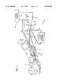
- FIG. 1is a block diagram illustrating an implement position control system for an off-highway vehicle.
- FIG. 2is a block diagram showing a hydraulic cylinder and a circuit for sensing the position of a rod eye attached to a piston moveable within the cylinder by transmitting and receiving electromagnetic (EM) bursts such as ultra-wideband (UWB) pulses between the rod eye and the cylinder.
- EMelectromagnetic
- UWBultra-wideband
- an electrohydraulic control system 10 used in an off-highway vehicleis shown.
- This systemcontrols the position or orientation of a joint or implement 12 (e.g., combine head, plow, bucket, blade, etc.) of an agricultural vehicle (e.g., tractor, combine, etc.), or construction vehicle (e.g., backhoe, crane, dozer, trencher, wheeled, tracked or skid-steer loader, etc.).
- a joint or implement 12e.g., combine head, plow, bucket, blade, etc.
- an agricultural vehiclee.g., tractor, combine, etc.
- construction vehiclee.g., backhoe, crane, dozer, trencher, wheeled, tracked or skid-steer loader, etc.
- Control system 10controls the position of implement 12 using an actuator 14 supplied with pressurized fluid (e.g., hydraulic fluid, air, etc.) from a valve assembly 16.
- Valve assembly 16receives raise and lower signals from a control unit 18 in response to commands from an operator interface 20.
- Control unit 18can control the position of implement 12 in a closed-loop as described below.
- Control unit 18includes a microprocessor-based circuit or a dedicated, specific-purpose hard-wired circuit.
- Operator interface 20includes operator-actuatable command devices such as potentiometers and switches which generate command signals sent to control unit 18 via a signal bus 22.
- the command signalsfor example, represent raise and lower signals, reference position signals, raise and lower rate signals and mode select signals (e.g., manual, replay, return-to-position, float or height control mode).
- Other applicationsinclude different command devices which generate command signals appropriate for the particular application.
- control unit 18In response to the command signals from operator interface 20, control unit 18 generates a raise signal 24 and a lower signal 26 which are applied to a raise solenoid 28 and a lower solenoid 30 mounted on valve assembly 16, respectively.
- Raise signal 24 and lower signal 26may be, for example, pulse-width-modulated (PWM) signals.
- valve assembly 16controls the flow of pressurized fluid between a source 32 and actuator 14.
- Source 32includes a pump connected in series with a fluid storage tank and filters (not shown). The fluid is transferred through conduits (e.g, hoses, tubes, etc.) 34, 36, 38 and 40.
- actuator 14includes a cylinder having a cylinder housing 42 and a cylinder rod 44 which is moved in the longitudinal direction of the cylinder by a piston 66 within cylinder housing 42.
- a pneumatic cylindermay be used for other applications.
- a pressurized gasis used as the fluid.
- the force which drives piston 66is provided by the pressurized hydraulic fluid supplied to actuator 14 by valve assembly 16.
- the actuator 14is connected between first and second attachment members 46 and 48 such that changes in the piston's position change the position or orientation of implement 12.
- Actuator 14can also be oriented in the reverse direction such that rod 44 connects to attachment member 46 instead of 48.
- Implement 12is supported by a vehicle (not shown) using a bearing assembly 50 including first and second bearing portions 52 and 54.
- First bearing portion 52is fixed and second bearing portion 54 is rotatable with respect to the vehicle.
- Implement 12is fastened to second bearing portion 54 such that implement 12 is rotatable about the axis of bearing assembly 50.
- First and second attachment members 46 and 48are connected to first bearing portion 52 and implement 12, respectively, so changes in extension of the cylinder cause implement 12 to rotate with respect to the vehicle.
- Control unit 18receives a position feedback signal from a position sensing arrangement 56 via a data conductor or bus 57. Depending upon the application, control unit 18 may also receive a pressure signal from a pressure sensor 58 via data conductor or bus 60. Position sensing arrangement 56 replaces other position sensors such as LVDTs mounted between implement 12 and bearing portion 52 by external linkages and operates based upon non-contact position sensing using radar. Pressure sensor 58 measures the pressure of the hydraulic fluid.
- command devices within operator interface 20send desired command signals to control unit 18.
- Control unit 18responds by generating raise and lower signals and applying them to raise and lower solenoids 28 and 30 of valve assembly 16.
- Valve assembly 16selectively controls the flow of pressurized hydraulic fluid from source 32 to front and rear ports of cylinder housing 42 which causes piston 66 within the cylinder to move longitudinally. Movement of piston 66 causes cylinder rod 44 to extend or retract, thereby changing the distance between attachment members 46 and 48. An increased distance causes implement 12 to rotate clockwise about bearing assembly 50 and a decreased distance causes implement 12 to rotate in the counterclockwise direction. Extension or retraction of actuator 14 is controlled by hydraulic fluid flow in and out of actuator 14, or can be determined by the interaction of implement 12 with the ground (e.g., in float mode).
- the position of implement 12 and the pressure (optional) of the fluidare provided to control unit 18 by position sensing arrangement 56 and pressure sensor 58 (optional).
- the position of implement 12can be controlled in closed-loop fashion based upon an error signal between the command signals from operator interface 20 and position feedback signals from the position sensing arrangement 56.
- Control system 10except for the position sensing arrangement and its interface, is further described in U.S. Pat. No. 5,455,769, commonly assigned and incorporated herein by reference.
- a control system for a tractor hitch assemblyis described in U.S. Pat. No. 5,421,416, and a system to move an arm on a construction vehicle using a cylinder is described in U.S. Pat. No. 5,000,650, both commonly assigned and incorporated herein by reference.
- position sensing arrangement 56determines the position or orientation of implement 12 based upon the position of a rod eye 62 connected to cylinder rod 44 relative to housing 42. Once the position of rod eye 62 is known, control unit 18 can calculate the position or orientation of implement 12 as a function of rod eye 62 position and the geometrical parameters of the machine system. Position sensing arrangement 56 includes micropower impulse radar (MIR) technology and operates as explained below.
- MIRmicropower impulse radar
- FIG. 2shows actuator 14 and an MIR circuit 64 for sensing the position of rod eye 62 by transmitting and receiving electromagnetic (EM) pulses or bursts between cylinder housing 42 and rod eye 62.
- EMelectromagnetic
- a sequence of EM burstsare generated by a pulser 68 and applied to a transmitter unit 70 via a transmission line 72.
- Transmitter unit 70is attached to rod eye 62 and a receiver unit 74 is attached to a back end 76 of cylinder housing 42.
- the positions of transmitter unit 70 and receiver unit 74can be reversed, or can be moved to other positions or structures having a fixed relationship to the positions of rod eye 62 and housing 42, respectively.
- Cylinder housing 42also has a front end 78 and a cylindrical side wall 80 between ends 76 and 78.
- transmitter unit 70 and receiver unit 74are attached so that the line of sight between an antenna 82 attached to transmitter unit 70 and an antenna 84 attached to receiver unit 74 is substantially parallel with the longitudinal axis of piston rod 44.
- This configurationprovides more accurate position sensing for rod eye 62.
- the positioncan be calculated by taking into account the angle ⁇ therebetween (e.g., cos ( ⁇ ) multiplied by line of sight distance).
- Transmitter and receiver units 70 and 74can be integral (i.e., one-piece) with their respective antennas 82 and 84, or can be separate from their respective antennas and connected by wires. An integral unit may be more cost-effective, while separate units may increase flexibility in mounting units 70 and 74.
- the transmitteris described in U.S. Pat. Nos. 5,457,394 and 5,517,198, incorporated herein by reference, and the receiver is described in U.S. Pat. Nos. 5,523,760 and 5,345,471, incorporated herein by reference.
- Transmitter unit 70 and receiver unit 74 discussed hereinare integral units for purposes of calculating the position of rod eye 62 relative to housing 42.
- MIR circuit 64includes a timing circuit 86, a receive strobe generator 88, pulser 68, transmitter unit 70 with associated antenna 82, and receiver unit 74 with associated antenna 84.
- Timing circuit 86generates a timing signal representative of the time for the EM bursts to travel from transmitter unit 70 to receiver unit 74.
- timing circuit 86includes a pulse timing oscillator 90, a controlled delay circuit 92, a start/stop circuit 94, a counter 96 and a processor 98. The operation of timing circuit 86 is described below.
- Pulse timing oscillator 90generates a transmit timing signal which is applied to pulser 68 over bus 100.
- the transmit timing signalis generated at a pulse repetition rate of approximately two megahertz.
- Pulser 68receives the transmit timing signal and generates real-time pulses which are applied to transmitter unit 70 over transmission line 72.
- Unit 70transmits the EM pulses through antenna 82 based upon the real-time pulses received from pulser 68.
- Pulse timing oscillator 90also supplies the transmit timing signal to controlled delay circuit 92 over a bus 102.
- Controlled delay circuit 92generates a receive timing signal over a bus 104.
- Receive strobe generator 88receives the receive timing signal and strobes a sample gate in receiver unit 74 at the pulse repetition rate, but at times which are delayed relative to the times transmitter unit 70 transmits the EM pulses.
- Controlled delay circuit 92is also coupled to start/stop circuit 94 via a bus 106.
- Start/stop circuit 94includes a sweep oscillator which oscillates at approximately 70 Hz and is designed to oscillate under 100 Hz.
- Start/stop circuit 94generates a ramp signal which is applied to controlled delay circuit 92 over bus 106 to control the timing of the strobes generated by receive strobe generator 88.
- Receiver unit 74generates a pulse detect signal in response to the samples of the sequence of EM pulses which is applied to start/stop circuit 94 over a bus 108.
- Start/stop circuit 94generates a start signal at the beginning of each sweep and a stop signal in response to the pulse detect signal detected on bus 108.
- the start signals and the stop signals generated by start/stop circuit 94are applied to controlled delay circuit 92 over bus 106.
- Start/stop circuit 94also supplies counter 96 with the start signals and the stop signals over a bus 110.
- counter 96Upon receipt of the start signal from start/stop circuit 94, counter 96 is initiated and begins counting at a rate of approximately ten megahertz.
- receiver unit 74detects the EM pulse
- receiver unit 74After receiver unit 74 detects the EM pulse, receiver unit 74 generates the pulse detect signal which is applied to start/stop circuit 94 over bus 108.
- Start/stop circuit 94then generates a stop signal which is applied to counter 96 over bus 110.
- the value of counter 96 upon receipt of the stop signalrepresents the timing signal.
- the timing signalis the time-of-flight of an EM pulse from transmitter unit 70 to receiver unit 74, which is the difference between the delay of a strobe pulse at the beginning of a sweep and the delay of a strobe pulse when the pulse detect signal is generated.
- Counter 96supplies the timing signal to processor 98 over a bus 112.
- Control unit 18includes a position signal generation circuit which determines the position of transmitter unit 70 based on the timing signal and converts the timing signal into a position signal representative of the distance between rod eye 62 and front end 76 of cylinder housing 42.
- the EM burstsare ultra-wideband (UWB) or square-wave pulses.
- U.S. Pat. No. 5,457,394, herein incorporated by referencedescribes a circuit including a generator of UWB pulses which are 200 psec wide, and are repeated at a pulse-repetition interval (PRI) of 1 Mhz.
- PRIpulse-repetition interval
- other pulse widths and PRIscan be used.
- the UWB pulsesare repeated to allow the integration or averaging of approximately 10,000 pulses for increased noise immunity. Noise immunity can be further increased by modulating (e.g., dithering or randomizing) the pulses.
- the UWB pulsesare unlike acoustic, RF and microwave signals since they are a sequence of impulses having no carrier frequency.
- UWB pulsesNo specific frequency is associated with the UWB pulses, and the frequency spectrum is related by the Fourier transform of the pulses.
- the UWB termrefers to the wide spectrum of frequencies comprising the pulses.
- a timing circuit for measuring the direct time-of-flight of the EM pulses or bursts between a transmitter and a receiveris described in U.S. Pat. No. 5,661,490, incorporated herein by reference.
- a pulse timing oscillator used to supply a transmit signal to a transmitter and a controlled delay circuit used to supply a receive timing signal to a receive strobe generatorare also described in this patent.
- the signalsare not limited to EM bursts.
- Other types of signals having different timing circuitse.g., ultrasonic or laser signals
- the EM burstsare not limited to square pulses and the bursts may include pulses having any shape and form, including pulses generated by a highly-focused antenna.
- the pulsesmay include sine-wave signals or a combination of sine-wave signals having a carrier frequency component in the RF, microwave, etc. signal range.
- the frequency pulsesare repeated at a predetermined frequency less than the frequency of the carrier.
- the circuitry for generating frequency pulsesis more complex and expensive than the circuitry used to generate square pulses.
- Circuit 64operates in the time domain since the position of piston 66 is measured by the equivalent timing signal generated by timing circuit 86.
- Pulser 68generates real-time pulses which are applied to transmitter unit 70.
- Transmitter unit 70transmits real-time signals through antenna 82 based upon the real-time pulses received from pulser 68.
- Circuit 64operates in the time domain regardless of whether the EM bursts include UWB pulses or pulses having a frequency component. Operation in the time domain simplifies the circuitry compared with operation in the frequency domain (e.g., measuring piston position by determining the resonance frequency of a cavity formed by the piston and the cylinder).
- U.S. Pat. No. 5,661,490more particularly describes the sampling of the real-time pulses over a range of delay and the generation of an equivalent time sample signal.
Landscapes
- Engineering & Computer Science (AREA)
- Physics & Mathematics (AREA)
- Fluid Mechanics (AREA)
- Mechanical Engineering (AREA)
- General Engineering & Computer Science (AREA)
- Health & Medical Sciences (AREA)
- Electromagnetism (AREA)
- Radar, Positioning & Navigation (AREA)
- Remote Sensing (AREA)
- Toxicology (AREA)
- Optics & Photonics (AREA)
- Actuator (AREA)
Abstract
Description
Claims (31)
Priority Applications (1)
| Application Number | Priority Date | Filing Date | Title |
|---|---|---|---|
| US09/215,359US6142059A (en) | 1996-11-27 | 1998-12-18 | Method and apparatus for sensing the orientation of a mechanical actuator |
Applications Claiming Priority (2)
| Application Number | Priority Date | Filing Date | Title |
|---|---|---|---|
| US08/753,791US5977778A (en) | 1996-11-27 | 1996-11-27 | Method and apparatus for sensing piston position |
| US09/215,359US6142059A (en) | 1996-11-27 | 1998-12-18 | Method and apparatus for sensing the orientation of a mechanical actuator |
Related Parent Applications (1)
| Application Number | Title | Priority Date | Filing Date |
|---|---|---|---|
| US08/753,791Continuation-In-PartUS5977778A (en) | 1996-11-27 | 1996-11-27 | Method and apparatus for sensing piston position |
Publications (1)
| Publication Number | Publication Date |
|---|---|
| US6142059Atrue US6142059A (en) | 2000-11-07 |
Family
ID=46255309
Family Applications (1)
| Application Number | Title | Priority Date | Filing Date |
|---|---|---|---|
| US09/215,359Expired - LifetimeUS6142059A (en) | 1996-11-27 | 1998-12-18 | Method and apparatus for sensing the orientation of a mechanical actuator |
Country Status (1)
| Country | Link |
|---|---|
| US (1) | US6142059A (en) |
Cited By (40)
| Publication number | Priority date | Publication date | Assignee | Title |
|---|---|---|---|---|
| US6295019B1 (en) | 1998-05-26 | 2001-09-25 | Time Domain Corporation | System and method for distance measurement by inphase and quadrature signals in a radio system |
| US6297773B1 (en) | 1998-03-23 | 2001-10-02 | Time Domain Corporation | System and method for position determination by impulse radio |
| WO2002093019A1 (en)* | 2001-05-16 | 2002-11-21 | Rosemount Inc. | Hydraulic piston position sensor |
| US6484620B2 (en)* | 2000-12-28 | 2002-11-26 | Case Corporation | Laser based reflective beam cylinder sensor |
| US20020180461A1 (en)* | 2001-06-04 | 2002-12-05 | Case Corporation | Multi-fiber cylinder position sensor using time-of-flight technique |
| US6722261B1 (en) | 2002-12-11 | 2004-04-20 | Rosemount Inc. | Hydraulic piston position sensor signal processing |
| US6722260B1 (en) | 2002-12-11 | 2004-04-20 | Rosemount Inc. | Hydraulic piston position sensor |
| US6725731B2 (en) | 2000-03-08 | 2004-04-27 | Rosemount Inc. | Bi-directional differential pressure flow sensor |
| US6789458B2 (en) | 2000-03-08 | 2004-09-14 | Rosemount Inc. | System for controlling hydraulic actuator |
| US6817252B2 (en) | 2000-03-08 | 2004-11-16 | Rosemount Inc. | Piston position measuring device |
| US6848323B2 (en) | 2000-03-08 | 2005-02-01 | Rosemount Inc. | Hydraulic actuator piston measurement apparatus and method |
| US6906625B1 (en) | 2000-02-24 | 2005-06-14 | Time Domain Corporation | System and method for information assimilation and functionality control based on positioning information obtained by impulse radio techniques |
| US6987073B2 (en) | 2000-08-21 | 2006-01-17 | Micron Technology, Inc. | Low selectivity deposition methods |
| EP2006549A1 (en)* | 2007-06-22 | 2008-12-24 | Festo AG & Co. KG | Measuring device for measuring at least one parameter in a liquid cylinder using microwaves |
| US20090322316A1 (en)* | 2008-06-30 | 2009-12-31 | Eaton Corporation | Hydraulic cylinder rod position sensing method |
| US20100050863A1 (en)* | 2008-08-29 | 2010-03-04 | Cowan Dynamics Inc. | Fluid-powered actuator having an internal position sensor and a sensor module therefor |
| US20100180367A1 (en)* | 2009-01-20 | 2010-07-22 | Geberit International Ag | Method and electronic control apparatus for contactlessly controlling a sanitary facility |
| WO2010114916A1 (en)* | 2009-04-01 | 2010-10-07 | Fedd Wireless, Llc | Wireless monitoring of pump jack sucker rod loading and position |
| ITBO20090588A1 (en)* | 2009-09-16 | 2011-03-17 | A M A S P A | OPERATING MACHINE |
| US20110232474A1 (en)* | 2008-12-05 | 2011-09-29 | Moog Inc. | Two-stage submersible actuators |
| WO2011131195A1 (en)* | 2010-04-18 | 2011-10-27 | Mikrofyn A/S | Measuring apparatus for excavating and similar equipment |
| WO2011131196A1 (en)* | 2010-04-18 | 2011-10-27 | Mikrofyn A/S | Positioning apparatus for excavating and similar equipment |
| US8069772B1 (en)* | 2008-06-18 | 2011-12-06 | Arnold Peterson | Systems and methods for controlling hydraulic actuators |
| US20110315415A1 (en)* | 2009-03-12 | 2011-12-29 | Caterpillar Japan Ltd. | Work machine |
| US8109197B1 (en)* | 2008-06-18 | 2012-02-07 | Arnold Peterson | Hydraulic control system and method |
| US8278779B2 (en) | 2011-02-07 | 2012-10-02 | General Electric Company | System and method for providing redundant power to a device |
| WO2012143171A1 (en)* | 2011-04-20 | 2012-10-26 | Robert Bosch Gmbh | Piston accumulator with device for determining the position of a separating element that is displaceable in the piston accumulator |
| US8351483B1 (en) | 2006-12-18 | 2013-01-08 | University Of South Florida | Architecture for ultra-wideband radio |
| US8558408B2 (en) | 2010-09-29 | 2013-10-15 | General Electric Company | System and method for providing redundant power to a device |
| CN105873822A (en)* | 2013-09-06 | 2016-08-17 | Tdc收购控股公司 | One-way time-of-flight distance measurement |
| US9631455B2 (en) | 2011-03-07 | 2017-04-25 | Moog Inc. | Subsea actuation system |
| US20180001728A1 (en)* | 2014-12-19 | 2018-01-04 | Sistemi Sospensioni S.P.A. | Regenerative hydraulic shock-absorber for vehicle suspension |
| US10118696B1 (en) | 2016-03-31 | 2018-11-06 | Steven M. Hoffberg | Steerable rotating projectile |
| US20190056485A1 (en)* | 2017-08-21 | 2019-02-21 | Hamilton Sundstrand Corporation | Short range ultrasonic measurement |
| CN109683520A (en)* | 2018-12-21 | 2019-04-26 | 广州励丰文化科技股份有限公司 | A kind of perform control method and control system based on position detection |
| CN109683568A (en)* | 2018-12-21 | 2019-04-26 | 广州励丰文化科技股份有限公司 | A kind of control method and control system of device of performing |
| EP3506038A1 (en)* | 2017-12-18 | 2019-07-03 | United Technologies Corporation | Fault detection assembly |
| US10787109B2 (en) | 2016-11-11 | 2020-09-29 | Herzog Railroad Services, Inc. | System and method for operating a ballast car hopper door |
| US11712637B1 (en) | 2018-03-23 | 2023-08-01 | Steven M. Hoffberg | Steerable disk or ball |
| US12016257B2 (en) | 2020-02-19 | 2024-06-25 | Sabanto, Inc. | Methods for detecting and clearing debris from planter gauge wheels, closing wheels and seed tubes |
Citations (79)
| Publication number | Priority date | Publication date | Assignee | Title |
|---|---|---|---|---|
| US3160836A (en)* | 1960-07-01 | 1964-12-08 | Guerin Engineering Inc | Electrohydraulic actuator |
| US3714846A (en)* | 1971-02-23 | 1973-02-06 | Sundstrand Corp | Hydrostatic-differential transmission |
| US3744344A (en)* | 1970-12-07 | 1973-07-10 | White Motor Corp | Control system for transmission |
| US3796111A (en)* | 1971-08-18 | 1974-03-12 | Sundstrand Corp | Hydromechanical multi-range transmission |
| US3903756A (en)* | 1973-02-14 | 1975-09-09 | Zahnradfabrik Friedrichshafen | Hydromechanical transmission |
| US4019404A (en)* | 1975-03-21 | 1977-04-26 | Sundstrand Corporation | Power transmission |
| US4126047A (en)* | 1977-04-25 | 1978-11-21 | The United States Of America As Represented By The Secretary Of The Air Force | Surface acoustic wave rate sensor and position indicator |
| US4138907A (en)* | 1975-08-04 | 1979-02-13 | International Harvester Company | Hydromechanical transmission with overspeed limited variable drive |
| US4259881A (en)* | 1977-12-29 | 1981-04-07 | Zahnradfabrik Friedrichshafen Ag | Hydromechanical load-splitting drive |
| US4348855A (en)* | 1980-09-22 | 1982-09-14 | International Harvester Company | Crop damage responsive control of rotor speed |
| DE3116333A1 (en)* | 1981-04-24 | 1982-11-18 | H. Kuhnke Gmbh Kg, 2427 Malente | Measuring system for contactlessly detecting positions of the piston rod of a piston/cylinder unit |
| US4471668A (en)* | 1980-07-10 | 1984-09-18 | Voith Getriebe Kg | Drive assembly with a prime mover and a flywheel |
| US4487002A (en)* | 1981-07-17 | 1984-12-11 | Gary W. Krutz | Automatic ground speed controller |
| US4520660A (en)* | 1980-12-22 | 1985-06-04 | Froude Consine Limited | Engine testing apparatus and methods |
| US4543649A (en)* | 1983-10-17 | 1985-09-24 | Teknar, Inc. | System for ultrasonically detecting the relative position of a moveable device |
| US4584472A (en)* | 1984-02-21 | 1986-04-22 | Caterpillar Industrial Inc. | Linear position encoder |
| US4588953A (en)* | 1983-08-11 | 1986-05-13 | General Motors Corporation | Microwave piston position location |
| GB2172995A (en)* | 1985-03-30 | 1986-10-01 | Emhart Ind | Monitoring the position of a member |
| US4631478A (en)* | 1982-05-19 | 1986-12-23 | Robert Bosch Gmbh | Method and apparatus for using spring-type resistive elements in a measurement bridge circuit |
| US4689553A (en)* | 1985-04-12 | 1987-08-25 | Jodon Engineering Associates, Inc. | Method and system for monitoring position of a fluid actuator employing microwave resonant cavity principles |
| US4694648A (en)* | 1982-12-13 | 1987-09-22 | Sundstrand Corporation | Anti-plug control |
| US4737705A (en)* | 1986-11-05 | 1988-04-12 | Caterpillar Inc. | Linear position sensor using a coaxial resonant cavity |
| US4742794A (en)* | 1986-09-08 | 1988-05-10 | Bennett Marine, Inc. | Trim tab indicator system |
| EP0266606A2 (en)* | 1986-11-03 | 1988-05-11 | Vickers Incorporated | Position determining apparatus |
| US4757745A (en)* | 1987-02-26 | 1988-07-19 | Vickers, Incorporated | Microwave antenna and dielectric property change frequency compensation system in electrohydraulic servo with piston position control |
| US4774465A (en)* | 1986-03-27 | 1988-09-27 | Vacuumschmelze Gmbh | Position sensor for generating a voltage changing proportionally to the position of a magnet |
| US4866269A (en)* | 1988-05-19 | 1989-09-12 | General Motors Corporation | Optical shaft position and speed sensor |
| US4901628A (en)* | 1983-08-11 | 1990-02-20 | General Motors Corporation | Hydraulic actuator having a microwave antenna |
| US4913004A (en)* | 1988-10-11 | 1990-04-03 | J. I. Case Company | Electronic powershift control system for an implement transmission |
| US4938054A (en)* | 1989-05-03 | 1990-07-03 | Gilbarco Inc. | Ultrasonic linear meter sensor for positive displacement meter |
| US4961055A (en)* | 1989-01-04 | 1990-10-02 | Vickers, Incorporated | Linear capacitance displacement transducer |
| US4987823A (en)* | 1989-07-10 | 1991-01-29 | Vickers, Incorporated | Location of piston position using radio frequency waves |
| US5000650A (en)* | 1989-05-12 | 1991-03-19 | J.I. Case Company | Automatic return to travel |
| EP0444472A2 (en)* | 1990-02-13 | 1991-09-04 | Michael Meyerle | Control system, particularly for motor vehicle |
| US5104144A (en)* | 1990-09-25 | 1992-04-14 | Monroe Auto Equipment Company | Shock absorber with sonar position sensor |
| US5150049A (en)* | 1991-06-24 | 1992-09-22 | Schuetz Tool & Die, Inc. | Magnetostrictive linear displacement transducer with temperature compensation |
| US5150060A (en)* | 1991-07-05 | 1992-09-22 | Caterpillar Inc. | Multiplexed radio frequency linear position sensor system |
| US5182980A (en)* | 1992-02-05 | 1993-02-02 | Caterpillar Inc. | Hydraulic cylinder position sensor mounting apparatus |
| US5182979A (en)* | 1992-03-02 | 1993-02-02 | Caterpillar Inc. | Linear position sensor with equalizing means |
| US5233293A (en)* | 1990-11-17 | 1993-08-03 | August Bilstein Gmbh & Co. Kg | Sensor for measuring the speed and/or position of a piston in relation to that of the cylinder it moves inside of in a dashpot or shock absorber |
| US5241278A (en)* | 1991-07-05 | 1993-08-31 | Caterpillar Inc. | Radio frequency linear position sensor using two subsequent harmonics |
| US5247172A (en)* | 1992-08-21 | 1993-09-21 | The Boeing Company | Position sensing system with magnetic coupling |
| US5260665A (en)* | 1991-04-30 | 1993-11-09 | Ivac Corporation | In-line fluid monitor system and method |
| US5274271A (en)* | 1991-07-12 | 1993-12-28 | Regents Of The University Of California | Ultra-short pulse generator |
| US5325063A (en)* | 1992-05-11 | 1994-06-28 | Caterpillar Inc. | Linear position sensor with means to eliminate spurians harmonic detections |
| US5332938A (en)* | 1992-04-06 | 1994-07-26 | Regents Of The University Of California | High voltage MOSFET switching circuit |
| US5345471A (en)* | 1993-04-12 | 1994-09-06 | The Regents Of The University Of California | Ultra-wideband receiver |
| DE4311084C1 (en)* | 1993-04-03 | 1994-09-22 | Man Nutzfahrzeuge Ag | Drive device of a vehicle |
| US5361070A (en)* | 1993-04-12 | 1994-11-01 | Regents Of The University Of California | Ultra-wideband radar motion sensor |
| DE9417204U1 (en)* | 1994-10-26 | 1995-02-09 | Alpine Westfalia Berg- und Tunneltechnik GmbH & Co., 44534 Lünen | Device for detecting the position and / or the speed of a piston of a cylinder-piston unit |
| US5422607A (en)* | 1994-02-09 | 1995-06-06 | The Regents Of The University Of California | Linear phase compressive filter |
| US5421416A (en)* | 1993-09-08 | 1995-06-06 | Case Corporation | Hitch assembly control system |
| US5438274A (en)* | 1991-12-23 | 1995-08-01 | Caterpillar | Linear position sensor using a coaxial resonant cavity |
| US5438261A (en)* | 1994-02-16 | 1995-08-01 | Caterpillar Inc. | Inductive sensing apparatus for a hydraulic cylinder |
| US5455769A (en)* | 1994-06-24 | 1995-10-03 | Case Corporation | Combine head raise and lower rate control |
| US5457394A (en)* | 1993-04-12 | 1995-10-10 | The Regents Of The University Of California | Impulse radar studfinder |
| US5465094A (en)* | 1994-01-14 | 1995-11-07 | The Regents Of The University Of California | Two terminal micropower radar sensor |
| US5471147A (en)* | 1991-10-03 | 1995-11-28 | Caterpillar Inc. | Apparatus and method for determining the linear position of a hydraulic cylinder |
| US5471162A (en)* | 1992-09-08 | 1995-11-28 | The Regents Of The University Of California | High speed transient sampler |
| US5494142A (en)* | 1994-08-01 | 1996-02-27 | Case Corporation | Power take off clutch engagement control system |
| US5505267A (en)* | 1994-11-14 | 1996-04-09 | Case Corporation | Differential lock control system for agricultural vehicles |
| US5510800A (en)* | 1993-04-12 | 1996-04-23 | The Regents Of The University Of California | Time-of-flight radio location system |
| US5517198A (en)* | 1993-04-12 | 1996-05-14 | The Regents Of The University Of California | Ultra-wideband directional sampler |
| US5519400A (en)* | 1993-04-12 | 1996-05-21 | The Regents Of The University Of California | Phase coded, micro-power impulse radar motion sensor |
| US5521600A (en)* | 1994-09-06 | 1996-05-28 | The Regents Of The University Of California | Range-gated field disturbance sensor with range-sensitivity compensation |
| US5523760A (en)* | 1993-04-12 | 1996-06-04 | The Regents Of The University Of California | Ultra-wideband receiver |
| US5536536A (en)* | 1994-12-12 | 1996-07-16 | Caterpillar Inc. | Protectively coated position sensor, the coating, and process for coating |
| US5540137A (en)* | 1994-10-11 | 1996-07-30 | Caterpillar Inc. | Electrical contacting in electromagnetic wave piston position sensing in a hydraulic cylinder |
| US5549185A (en)* | 1994-08-01 | 1996-08-27 | Case Corporation | Power take off torque limiting control system |
| US5563605A (en)* | 1995-08-02 | 1996-10-08 | The Regents Of The University Of California | Precision digital pulse phase generator |
| US5573012A (en)* | 1994-08-09 | 1996-11-12 | The Regents Of The University Of California | Body monitoring and imaging apparatus and method |
| US5576627A (en)* | 1994-09-06 | 1996-11-19 | The Regents Of The University Of California | Narrow field electromagnetic sensor system and method |
| US5581256A (en)* | 1994-09-06 | 1996-12-03 | The Regents Of The University Of California | Range gated strip proximity sensor |
| US5589838A (en)* | 1994-09-06 | 1996-12-31 | The Regents Of The University Of California | Short range radio locator system |
| US5609059A (en)* | 1994-12-19 | 1997-03-11 | The Regents Of The University Of California | Electronic multi-purpose material level sensor |
| US5617034A (en)* | 1995-05-09 | 1997-04-01 | Caterpillar Inc. | Signal improvement in the sensing of hydraulic cylinder piston position using electromagnetic waves |
| US5661490A (en)* | 1993-04-12 | 1997-08-26 | The Regents Of The University Of California | Time-of-flight radio location system |
| US5667452A (en)* | 1995-04-06 | 1997-09-16 | Caterpillar Inc. | Split torque transmission |
| US5977778A (en)* | 1996-11-27 | 1999-11-02 | Case Corporation | Method and apparatus for sensing piston position |
- 1998
- 1998-12-18USUS09/215,359patent/US6142059A/ennot_activeExpired - Lifetime
Patent Citations (85)
| Publication number | Priority date | Publication date | Assignee | Title |
|---|---|---|---|---|
| US3160836A (en)* | 1960-07-01 | 1964-12-08 | Guerin Engineering Inc | Electrohydraulic actuator |
| US3744344A (en)* | 1970-12-07 | 1973-07-10 | White Motor Corp | Control system for transmission |
| US3714846A (en)* | 1971-02-23 | 1973-02-06 | Sundstrand Corp | Hydrostatic-differential transmission |
| US3796111A (en)* | 1971-08-18 | 1974-03-12 | Sundstrand Corp | Hydromechanical multi-range transmission |
| US3903756A (en)* | 1973-02-14 | 1975-09-09 | Zahnradfabrik Friedrichshafen | Hydromechanical transmission |
| US4019404A (en)* | 1975-03-21 | 1977-04-26 | Sundstrand Corporation | Power transmission |
| US4138907A (en)* | 1975-08-04 | 1979-02-13 | International Harvester Company | Hydromechanical transmission with overspeed limited variable drive |
| US4126047A (en)* | 1977-04-25 | 1978-11-21 | The United States Of America As Represented By The Secretary Of The Air Force | Surface acoustic wave rate sensor and position indicator |
| US4259881A (en)* | 1977-12-29 | 1981-04-07 | Zahnradfabrik Friedrichshafen Ag | Hydromechanical load-splitting drive |
| US4471668A (en)* | 1980-07-10 | 1984-09-18 | Voith Getriebe Kg | Drive assembly with a prime mover and a flywheel |
| US4348855A (en)* | 1980-09-22 | 1982-09-14 | International Harvester Company | Crop damage responsive control of rotor speed |
| US4520660A (en)* | 1980-12-22 | 1985-06-04 | Froude Consine Limited | Engine testing apparatus and methods |
| DE3116333A1 (en)* | 1981-04-24 | 1982-11-18 | H. Kuhnke Gmbh Kg, 2427 Malente | Measuring system for contactlessly detecting positions of the piston rod of a piston/cylinder unit |
| US4487002A (en)* | 1981-07-17 | 1984-12-11 | Gary W. Krutz | Automatic ground speed controller |
| US4631478A (en)* | 1982-05-19 | 1986-12-23 | Robert Bosch Gmbh | Method and apparatus for using spring-type resistive elements in a measurement bridge circuit |
| US4694648A (en)* | 1982-12-13 | 1987-09-22 | Sundstrand Corporation | Anti-plug control |
| US4901628A (en)* | 1983-08-11 | 1990-02-20 | General Motors Corporation | Hydraulic actuator having a microwave antenna |
| US4588953A (en)* | 1983-08-11 | 1986-05-13 | General Motors Corporation | Microwave piston position location |
| US4543649A (en)* | 1983-10-17 | 1985-09-24 | Teknar, Inc. | System for ultrasonically detecting the relative position of a moveable device |
| US4584472A (en)* | 1984-02-21 | 1986-04-22 | Caterpillar Industrial Inc. | Linear position encoder |
| GB2172995A (en)* | 1985-03-30 | 1986-10-01 | Emhart Ind | Monitoring the position of a member |
| US4689553A (en)* | 1985-04-12 | 1987-08-25 | Jodon Engineering Associates, Inc. | Method and system for monitoring position of a fluid actuator employing microwave resonant cavity principles |
| US4774465A (en)* | 1986-03-27 | 1988-09-27 | Vacuumschmelze Gmbh | Position sensor for generating a voltage changing proportionally to the position of a magnet |
| US4742794A (en)* | 1986-09-08 | 1988-05-10 | Bennett Marine, Inc. | Trim tab indicator system |
| US4749936A (en)* | 1986-11-03 | 1988-06-07 | Vickers, Incorporated | Power transmission |
| EP0266606A2 (en)* | 1986-11-03 | 1988-05-11 | Vickers Incorporated | Position determining apparatus |
| US4737705A (en)* | 1986-11-05 | 1988-04-12 | Caterpillar Inc. | Linear position sensor using a coaxial resonant cavity |
| US4757745A (en)* | 1987-02-26 | 1988-07-19 | Vickers, Incorporated | Microwave antenna and dielectric property change frequency compensation system in electrohydraulic servo with piston position control |
| US4866269A (en)* | 1988-05-19 | 1989-09-12 | General Motors Corporation | Optical shaft position and speed sensor |
| US4913004A (en)* | 1988-10-11 | 1990-04-03 | J. I. Case Company | Electronic powershift control system for an implement transmission |
| US4961055A (en)* | 1989-01-04 | 1990-10-02 | Vickers, Incorporated | Linear capacitance displacement transducer |
| US4938054A (en)* | 1989-05-03 | 1990-07-03 | Gilbarco Inc. | Ultrasonic linear meter sensor for positive displacement meter |
| US5000650A (en)* | 1989-05-12 | 1991-03-19 | J.I. Case Company | Automatic return to travel |
| US4987823A (en)* | 1989-07-10 | 1991-01-29 | Vickers, Incorporated | Location of piston position using radio frequency waves |
| EP0444472A2 (en)* | 1990-02-13 | 1991-09-04 | Michael Meyerle | Control system, particularly for motor vehicle |
| US5104144A (en)* | 1990-09-25 | 1992-04-14 | Monroe Auto Equipment Company | Shock absorber with sonar position sensor |
| US5233293A (en)* | 1990-11-17 | 1993-08-03 | August Bilstein Gmbh & Co. Kg | Sensor for measuring the speed and/or position of a piston in relation to that of the cylinder it moves inside of in a dashpot or shock absorber |
| US5260665A (en)* | 1991-04-30 | 1993-11-09 | Ivac Corporation | In-line fluid monitor system and method |
| US5150049A (en)* | 1991-06-24 | 1992-09-22 | Schuetz Tool & Die, Inc. | Magnetostrictive linear displacement transducer with temperature compensation |
| US5241278A (en)* | 1991-07-05 | 1993-08-31 | Caterpillar Inc. | Radio frequency linear position sensor using two subsequent harmonics |
| US5150060A (en)* | 1991-07-05 | 1992-09-22 | Caterpillar Inc. | Multiplexed radio frequency linear position sensor system |
| US5274271A (en)* | 1991-07-12 | 1993-12-28 | Regents Of The University Of California | Ultra-short pulse generator |
| US5471147A (en)* | 1991-10-03 | 1995-11-28 | Caterpillar Inc. | Apparatus and method for determining the linear position of a hydraulic cylinder |
| US5438274A (en)* | 1991-12-23 | 1995-08-01 | Caterpillar | Linear position sensor using a coaxial resonant cavity |
| US5491422A (en)* | 1991-12-23 | 1996-02-13 | Caterpillar Inc. | Linear position sensor using a coaxial resonant cavity |
| US5182980A (en)* | 1992-02-05 | 1993-02-02 | Caterpillar Inc. | Hydraulic cylinder position sensor mounting apparatus |
| US5182979A (en)* | 1992-03-02 | 1993-02-02 | Caterpillar Inc. | Linear position sensor with equalizing means |
| US5332938A (en)* | 1992-04-06 | 1994-07-26 | Regents Of The University Of California | High voltage MOSFET switching circuit |
| US5325063A (en)* | 1992-05-11 | 1994-06-28 | Caterpillar Inc. | Linear position sensor with means to eliminate spurians harmonic detections |
| US5247172A (en)* | 1992-08-21 | 1993-09-21 | The Boeing Company | Position sensing system with magnetic coupling |
| US5519342A (en)* | 1992-09-08 | 1996-05-21 | The Regents Of The University Of California | Transient digitizer with displacement current samplers |
| US5479120A (en)* | 1992-09-08 | 1995-12-26 | The Regents Of The University Of California | High speed sampler and demultiplexer |
| US5471162A (en)* | 1992-09-08 | 1995-11-28 | The Regents Of The University Of California | High speed transient sampler |
| DE4311084C1 (en)* | 1993-04-03 | 1994-09-22 | Man Nutzfahrzeuge Ag | Drive device of a vehicle |
| US5345471A (en)* | 1993-04-12 | 1994-09-06 | The Regents Of The University Of California | Ultra-wideband receiver |
| US5510800A (en)* | 1993-04-12 | 1996-04-23 | The Regents Of The University Of California | Time-of-flight radio location system |
| US5457394A (en)* | 1993-04-12 | 1995-10-10 | The Regents Of The University Of California | Impulse radar studfinder |
| US5523760A (en)* | 1993-04-12 | 1996-06-04 | The Regents Of The University Of California | Ultra-wideband receiver |
| US5519400A (en)* | 1993-04-12 | 1996-05-21 | The Regents Of The University Of California | Phase coded, micro-power impulse radar motion sensor |
| US5517198A (en)* | 1993-04-12 | 1996-05-14 | The Regents Of The University Of California | Ultra-wideband directional sampler |
| US5661490A (en)* | 1993-04-12 | 1997-08-26 | The Regents Of The University Of California | Time-of-flight radio location system |
| US5361070B1 (en)* | 1993-04-12 | 2000-05-16 | Univ California | Ultra-wideband radar motion sensor |
| US5361070A (en)* | 1993-04-12 | 1994-11-01 | Regents Of The University Of California | Ultra-wideband radar motion sensor |
| US5512834A (en)* | 1993-05-07 | 1996-04-30 | The Regents Of The University Of California | Homodyne impulse radar hidden object locator |
| US5421416A (en)* | 1993-09-08 | 1995-06-06 | Case Corporation | Hitch assembly control system |
| US5465094A (en)* | 1994-01-14 | 1995-11-07 | The Regents Of The University Of California | Two terminal micropower radar sensor |
| US5422607A (en)* | 1994-02-09 | 1995-06-06 | The Regents Of The University Of California | Linear phase compressive filter |
| US5438261A (en)* | 1994-02-16 | 1995-08-01 | Caterpillar Inc. | Inductive sensing apparatus for a hydraulic cylinder |
| US5455769A (en)* | 1994-06-24 | 1995-10-03 | Case Corporation | Combine head raise and lower rate control |
| US5494142A (en)* | 1994-08-01 | 1996-02-27 | Case Corporation | Power take off clutch engagement control system |
| US5549185A (en)* | 1994-08-01 | 1996-08-27 | Case Corporation | Power take off torque limiting control system |
| US5573012A (en)* | 1994-08-09 | 1996-11-12 | The Regents Of The University Of California | Body monitoring and imaging apparatus and method |
| US5576627A (en)* | 1994-09-06 | 1996-11-19 | The Regents Of The University Of California | Narrow field electromagnetic sensor system and method |
| US5521600A (en)* | 1994-09-06 | 1996-05-28 | The Regents Of The University Of California | Range-gated field disturbance sensor with range-sensitivity compensation |
| US5581256A (en)* | 1994-09-06 | 1996-12-03 | The Regents Of The University Of California | Range gated strip proximity sensor |
| US5589838A (en)* | 1994-09-06 | 1996-12-31 | The Regents Of The University Of California | Short range radio locator system |
| US5540137A (en)* | 1994-10-11 | 1996-07-30 | Caterpillar Inc. | Electrical contacting in electromagnetic wave piston position sensing in a hydraulic cylinder |
| DE9417204U1 (en)* | 1994-10-26 | 1995-02-09 | Alpine Westfalia Berg- und Tunneltechnik GmbH & Co., 44534 Lünen | Device for detecting the position and / or the speed of a piston of a cylinder-piston unit |
| US5505267A (en)* | 1994-11-14 | 1996-04-09 | Case Corporation | Differential lock control system for agricultural vehicles |
| US5536536A (en)* | 1994-12-12 | 1996-07-16 | Caterpillar Inc. | Protectively coated position sensor, the coating, and process for coating |
| US5609059A (en)* | 1994-12-19 | 1997-03-11 | The Regents Of The University Of California | Electronic multi-purpose material level sensor |
| US5667452A (en)* | 1995-04-06 | 1997-09-16 | Caterpillar Inc. | Split torque transmission |
| US5617034A (en)* | 1995-05-09 | 1997-04-01 | Caterpillar Inc. | Signal improvement in the sensing of hydraulic cylinder piston position using electromagnetic waves |
| US5563605A (en)* | 1995-08-02 | 1996-10-08 | The Regents Of The University Of California | Precision digital pulse phase generator |
| US5977778A (en)* | 1996-11-27 | 1999-11-02 | Case Corporation | Method and apparatus for sensing piston position |
Non-Patent Citations (9)
| Title |
|---|
| Brochure: DC Hydrastar, Position Transducer.* |
| Brochure: Penny Giles Product Data, Cylinder Transducer Model HLP100.* |
| Brochure: Penny Giles, Technology Leaders in Displacement Monitoring & Manual Control, Jul., 1989.* |
| Brochure: Penny+Giles Product Data, Cylinder Transducer Model HLP100. |
| Brochure: Penny+Giles, Technology Leaders in Displacement Monitoring & Manual Control, Jul., 1989. |
| Brochure: TECHNIK, Absolute Position Measurement Using Conductive Plastic Potentiometers.* |
| Brochure: Understanding Magnetostrictive LDTs, Hydraulics & Pneumatics, by W.D. Peterson, Feb., 1993.* |
| Magazine: Business Week, Not Just a Blip on the Screen, Feb. 19, 1996.* |
| Sensors: An LVDT Primer, Jun., 1996.* |
Cited By (71)
| Publication number | Priority date | Publication date | Assignee | Title |
|---|---|---|---|---|
| US6611234B2 (en) | 1998-03-23 | 2003-08-26 | Time Domain Corporation | System and method for position determination by impulse radio using round trip time-of-flight |
| US6297773B1 (en) | 1998-03-23 | 2001-10-02 | Time Domain Corporation | System and method for position determination by impulse radio |
| US6300903B1 (en) | 1998-03-23 | 2001-10-09 | Time Domain Corporation | System and method for person or object position location utilizing impulse radio |
| US6295019B1 (en) | 1998-05-26 | 2001-09-25 | Time Domain Corporation | System and method for distance measurement by inphase and quadrature signals in a radio system |
| US20050254354A1 (en)* | 2000-02-24 | 2005-11-17 | Time Domain Corporation | System and method for information assimilation and functionality control based on positioning information obtained by impulse radio means |
| US6906625B1 (en) | 2000-02-24 | 2005-06-14 | Time Domain Corporation | System and method for information assimilation and functionality control based on positioning information obtained by impulse radio techniques |
| US7170408B2 (en) | 2000-02-24 | 2007-01-30 | Time Domain Corporation | System and method for information assimilation and functionality control based on positioning information obtained by impulse radio means |
| US6789458B2 (en) | 2000-03-08 | 2004-09-14 | Rosemount Inc. | System for controlling hydraulic actuator |
| US6725731B2 (en) | 2000-03-08 | 2004-04-27 | Rosemount Inc. | Bi-directional differential pressure flow sensor |
| US6817252B2 (en) | 2000-03-08 | 2004-11-16 | Rosemount Inc. | Piston position measuring device |
| US6848323B2 (en) | 2000-03-08 | 2005-02-01 | Rosemount Inc. | Hydraulic actuator piston measurement apparatus and method |
| US6987073B2 (en) | 2000-08-21 | 2006-01-17 | Micron Technology, Inc. | Low selectivity deposition methods |
| US6484620B2 (en)* | 2000-12-28 | 2002-11-26 | Case Corporation | Laser based reflective beam cylinder sensor |
| US6588313B2 (en) | 2001-05-16 | 2003-07-08 | Rosemont Inc. | Hydraulic piston position sensor |
| WO2002093019A1 (en)* | 2001-05-16 | 2002-11-21 | Rosemount Inc. | Hydraulic piston position sensor |
| US20020180461A1 (en)* | 2001-06-04 | 2002-12-05 | Case Corporation | Multi-fiber cylinder position sensor using time-of-flight technique |
| US6769349B2 (en)* | 2001-06-04 | 2004-08-03 | Case Corporation | Multi-fiber cylinder position sensor using time-of-flight technique |
| US6722260B1 (en) | 2002-12-11 | 2004-04-20 | Rosemount Inc. | Hydraulic piston position sensor |
| CN1316169C (en)* | 2002-12-11 | 2007-05-16 | 罗斯蒙德公司 | Hydraulic piston position sensor signal processing |
| US6722261B1 (en) | 2002-12-11 | 2004-04-20 | Rosemount Inc. | Hydraulic piston position sensor signal processing |
| US8351483B1 (en) | 2006-12-18 | 2013-01-08 | University Of South Florida | Architecture for ultra-wideband radio |
| US8588270B1 (en) | 2006-12-18 | 2013-11-19 | University Of South Florida | Architecture for ultra-wideband radio |
| US8724677B1 (en) | 2006-12-18 | 2014-05-13 | University Of South Florida | Architecture for ultra-wideband radio |
| EP2006549A1 (en)* | 2007-06-22 | 2008-12-24 | Festo AG & Co. KG | Measuring device for measuring at least one parameter in a liquid cylinder using microwaves |
| US8109197B1 (en)* | 2008-06-18 | 2012-02-07 | Arnold Peterson | Hydraulic control system and method |
| US8763513B1 (en) | 2008-06-18 | 2014-07-01 | Arnold Peterson | Hydraulic control system and method |
| US8069772B1 (en)* | 2008-06-18 | 2011-12-06 | Arnold Peterson | Systems and methods for controlling hydraulic actuators |
| US20090322316A1 (en)* | 2008-06-30 | 2009-12-31 | Eaton Corporation | Hydraulic cylinder rod position sensing method |
| US7982459B2 (en) | 2008-06-30 | 2011-07-19 | Eaton Corporation | Hydraulic cylinder rod position sensing method |
| US8448563B2 (en) | 2008-08-29 | 2013-05-28 | Cowan Dynamics Inc. | Fluid-powered actuator having an internal position sensor and a sensor module therefor |
| US20100050863A1 (en)* | 2008-08-29 | 2010-03-04 | Cowan Dynamics Inc. | Fluid-powered actuator having an internal position sensor and a sensor module therefor |
| US20110232474A1 (en)* | 2008-12-05 | 2011-09-29 | Moog Inc. | Two-stage submersible actuators |
| US8857175B2 (en)* | 2008-12-05 | 2014-10-14 | Moog Inc. | Two-stage submersible actuators |
| US20100180367A1 (en)* | 2009-01-20 | 2010-07-22 | Geberit International Ag | Method and electronic control apparatus for contactlessly controlling a sanitary facility |
| US20110315415A1 (en)* | 2009-03-12 | 2011-12-29 | Caterpillar Japan Ltd. | Work machine |
| US9309649B2 (en)* | 2009-03-12 | 2016-04-12 | Caterpillar Sarl | Work machine |
| US20120020808A1 (en)* | 2009-04-01 | 2012-01-26 | Lawson Rick A | Wireless Monitoring of Pump Jack Sucker Rod Loading and Position |
| WO2010114916A1 (en)* | 2009-04-01 | 2010-10-07 | Fedd Wireless, Llc | Wireless monitoring of pump jack sucker rod loading and position |
| ITBO20090588A1 (en)* | 2009-09-16 | 2011-03-17 | A M A S P A | OPERATING MACHINE |
| AU2011242170B2 (en)* | 2010-04-18 | 2015-12-03 | Leica Geosystems Technology A/S | Positioning apparatus for excavating and similar equipment |
| AU2011242169B2 (en)* | 2010-04-18 | 2015-11-26 | Leica Geosystems Technology A/S | Measuring apparatus for excavating and similar equipment |
| CN102918210A (en)* | 2010-04-18 | 2013-02-06 | 米克洛夫伊恩股份公司 | Positioning devices and similar equipment for excavation |
| US8654608B2 (en) | 2010-04-18 | 2014-02-18 | Mikrofyn A/S | Positioning apparatus for excavating and similar equipment |
| CN102918209A (en)* | 2010-04-18 | 2013-02-06 | 米克洛夫伊恩股份公司 | Measuring apparatus for excavating and similar equipment |
| WO2011131195A1 (en)* | 2010-04-18 | 2011-10-27 | Mikrofyn A/S | Measuring apparatus for excavating and similar equipment |
| US8843266B2 (en) | 2010-04-18 | 2014-09-23 | Mikrofyn A/S | Positioning apparatus for excavating and similar equipment |
| EP2563977A4 (en)* | 2010-04-18 | 2016-01-06 | Mikrofyn As | MEASURING APPARATUS FOR EXCAVATION EQUIPMENT AND THE LIKE |
| CN102918209B (en)* | 2010-04-18 | 2015-02-04 | 米克洛夫伊恩股份公司 | Measuring apparatus for excavating and similar equipment |
| CN102918210B (en)* | 2010-04-18 | 2015-04-29 | 米克洛夫伊恩股份公司 | Positioning devices and similar equipment for excavation |
| EP2563978A4 (en)* | 2010-04-18 | 2017-03-01 | Mikrofyn A/S | Positioning apparatus for excavating and similar equipment |
| WO2011131196A1 (en)* | 2010-04-18 | 2011-10-27 | Mikrofyn A/S | Positioning apparatus for excavating and similar equipment |
| US8558408B2 (en) | 2010-09-29 | 2013-10-15 | General Electric Company | System and method for providing redundant power to a device |
| US8278779B2 (en) | 2011-02-07 | 2012-10-02 | General Electric Company | System and method for providing redundant power to a device |
| US9631455B2 (en) | 2011-03-07 | 2017-04-25 | Moog Inc. | Subsea actuation system |
| WO2012143171A1 (en)* | 2011-04-20 | 2012-10-26 | Robert Bosch Gmbh | Piston accumulator with device for determining the position of a separating element that is displaceable in the piston accumulator |
| EP3041736A4 (en)* | 2013-09-06 | 2016-10-05 | Tdc Acquisition Holdings Inc | DISTANCE MEASUREMENT OF FLIGHT |
| CN105873822A (en)* | 2013-09-06 | 2016-08-17 | Tdc收购控股公司 | One-way time-of-flight distance measurement |
| CN105873822B (en)* | 2013-09-06 | 2018-11-13 | Lm风力发电公司 | One-way time-of-flight distance measurement |
| US20180001728A1 (en)* | 2014-12-19 | 2018-01-04 | Sistemi Sospensioni S.P.A. | Regenerative hydraulic shock-absorber for vehicle suspension |
| US10052926B2 (en)* | 2014-12-19 | 2018-08-21 | Sistemi Sospensioni S.P.A. | Regenerative hydraulic shock-absorber for vehicle suspension |
| US10118696B1 (en) | 2016-03-31 | 2018-11-06 | Steven M. Hoffberg | Steerable rotating projectile |
| US11230375B1 (en) | 2016-03-31 | 2022-01-25 | Steven M. Hoffberg | Steerable rotating projectile |
| US10787109B2 (en) | 2016-11-11 | 2020-09-29 | Herzog Railroad Services, Inc. | System and method for operating a ballast car hopper door |
| US10495740B2 (en)* | 2017-08-21 | 2019-12-03 | Hamilton Sundstrand Corporation | Short range ultrasonic measurement |
| US20190056485A1 (en)* | 2017-08-21 | 2019-02-21 | Hamilton Sundstrand Corporation | Short range ultrasonic measurement |
| EP3506038A1 (en)* | 2017-12-18 | 2019-07-03 | United Technologies Corporation | Fault detection assembly |
| US10815902B2 (en) | 2017-12-18 | 2020-10-27 | Raytheon Technologies Corporation | Fault detection assembly |
| US11712637B1 (en) | 2018-03-23 | 2023-08-01 | Steven M. Hoffberg | Steerable disk or ball |
| CN109683568A (en)* | 2018-12-21 | 2019-04-26 | 广州励丰文化科技股份有限公司 | A kind of control method and control system of device of performing |
| CN109683520A (en)* | 2018-12-21 | 2019-04-26 | 广州励丰文化科技股份有限公司 | A kind of perform control method and control system based on position detection |
| US12016257B2 (en) | 2020-02-19 | 2024-06-25 | Sabanto, Inc. | Methods for detecting and clearing debris from planter gauge wheels, closing wheels and seed tubes |
Similar Documents
| Publication | Publication Date | Title |
|---|---|---|
| US6142059A (en) | Method and apparatus for sensing the orientation of a mechanical actuator | |
| US5977778A (en) | Method and apparatus for sensing piston position | |
| US6005395A (en) | Method and apparatus for sensing piston position | |
| US5901633A (en) | Method and apparatus for sensing piston position using a dipstick assembly | |
| KR101834300B1 (en) | Positioning apparatus for excavating and similar equipment | |
| US6615114B1 (en) | Calibration system and method for work machines using electro hydraulic controls | |
| US10030366B2 (en) | Drawbar position determination with rotational sensors | |
| US6282453B1 (en) | Method for controlling a work implement to prevent interference with a work machine | |
| US10066370B2 (en) | Sensor fusion for implement position estimation and control | |
| AU2011242170A1 (en) | Positioning apparatus for excavating and similar equipment | |
| US4132273A (en) | Tractor hitch control system having safety features | |
| GB2352460A (en) | Determining the cross slope of a surface created by an earth moving machine | |
| DE10393842T5 (en) | Hydraulic piston position sensor signal processing | |
| JPH111942A (en) | Control method and device for tool of work machine | |
| US6129155A (en) | Method and apparatus for controlling a work implement having multiple degrees of freedom | |
| EP0941409A1 (en) | Method and apparatus for sensing piston position | |
| WO1998023867A9 (en) | Method and apparatus for sensing piston position | |
| CN112049427A (en) | Arm support control system and method and working vehicle | |
| US20150096440A1 (en) | Position sensor assembly in a hydraulic cylinder | |
| US20080134547A1 (en) | System For Position Detection | |
| US5880681A (en) | Apparatus for determining the position of a work implement | |
| JPH01178621A (en) | Bucket control device for power excavator work equipment | |
| US6473679B1 (en) | Angular velocity control and associated method for a boom of a machine | |
| JP2003206902A (en) | Method for controlling deadband of fluid system | |
| JP3880698B2 (en) | Bulldozer blade tilt angle limiter |
Legal Events
| Date | Code | Title | Description |
|---|---|---|---|
| AS | Assignment | Owner name:CASE CORPORATION, WISCONSIN Free format text:ASSIGNMENT OF ASSIGNORS INTEREST;ASSIGNORS:CHAN, DANLEY C.;BERGER, ALAN D.;REEL/FRAME:009665/0104;SIGNING DATES FROM 19981204 TO 19981208 | |
| STCF | Information on status: patent grant | Free format text:PATENTED CASE | |
| FPAY | Fee payment | Year of fee payment:4 | |
| AS | Assignment | Owner name:CNH AMERICA LLC, PENNSYLVANIA Free format text:ASSIGNMENT OF ASSIGNORS INTEREST;ASSIGNOR:CASE CORPORATION;REEL/FRAME:014981/0944 Effective date:20040805 | |
| AS | Assignment | Owner name:CNH AMERICA LLC, PENNSYLVANIA Free format text:ASSIGNMENT OF ASSIGNORS INTEREST;ASSIGNOR:CNH AMERICA LLC;REEL/FRAME:017766/0484 Effective date:20060606 Owner name:BLUE LEAF I.P., INC., DELAWARE Free format text:ASSIGNMENT OF ASSIGNORS INTEREST;ASSIGNOR:CNH AMERICA LLC;REEL/FRAME:017766/0484 Effective date:20060606 | |
| FPAY | Fee payment | Year of fee payment:8 | |
| FPAY | Fee payment | Year of fee payment:12 |