US6141806A - Bariatric bed - Google Patents
Bariatric bedDownload PDFInfo
- Publication number
- US6141806A US6141806AUS09/266,959US26695999AUS6141806AUS 6141806 AUS6141806 AUS 6141806AUS 26695999 AUS26695999 AUS 26695999AUS 6141806 AUS6141806 AUS 6141806A
- Authority
- US
- United States
- Prior art keywords
- cushion
- air bladder
- coupled
- cover
- elevated
- Prior art date
- Legal status (The legal status is an assumption and is not a legal conclusion. Google has not performed a legal analysis and makes no representation as to the accuracy of the status listed.)
- Expired - Lifetime
Links
Images


Classifications
- A—HUMAN NECESSITIES
- A61—MEDICAL OR VETERINARY SCIENCE; HYGIENE
- A61G—TRANSPORT, PERSONAL CONVEYANCES, OR ACCOMMODATION SPECIALLY ADAPTED FOR PATIENTS OR DISABLED PERSONS; OPERATING TABLES OR CHAIRS; CHAIRS FOR DENTISTRY; FUNERAL DEVICES
- A61G7/00—Beds specially adapted for nursing; Devices for lifting patients or disabled persons
- A61G7/05—Parts, details or accessories of beds
- A61G7/0507—Side-rails
- A—HUMAN NECESSITIES
- A61—MEDICAL OR VETERINARY SCIENCE; HYGIENE
- A61G—TRANSPORT, PERSONAL CONVEYANCES, OR ACCOMMODATION SPECIALLY ADAPTED FOR PATIENTS OR DISABLED PERSONS; OPERATING TABLES OR CHAIRS; CHAIRS FOR DENTISTRY; FUNERAL DEVICES
- A61G7/00—Beds specially adapted for nursing; Devices for lifting patients or disabled persons
- A61G7/002—Beds specially adapted for nursing; Devices for lifting patients or disabled persons having adjustable mattress frame
- A61G7/015—Beds specially adapted for nursing; Devices for lifting patients or disabled persons having adjustable mattress frame divided into different adjustable sections, e.g. for Gatch position
- A—HUMAN NECESSITIES
- A61—MEDICAL OR VETERINARY SCIENCE; HYGIENE
- A61G—TRANSPORT, PERSONAL CONVEYANCES, OR ACCOMMODATION SPECIALLY ADAPTED FOR PATIENTS OR DISABLED PERSONS; OPERATING TABLES OR CHAIRS; CHAIRS FOR DENTISTRY; FUNERAL DEVICES
- A61G7/00—Beds specially adapted for nursing; Devices for lifting patients or disabled persons
- A61G7/05—Parts, details or accessories of beds
- A61G7/0507—Side-rails
- A61G7/0508—Side-rails characterised by a particular connection mechanism
- A61G7/051—Side-rails characterised by a particular connection mechanism pivoting sideward
- A—HUMAN NECESSITIES
- A61—MEDICAL OR VETERINARY SCIENCE; HYGIENE
- A61G—TRANSPORT, PERSONAL CONVEYANCES, OR ACCOMMODATION SPECIALLY ADAPTED FOR PATIENTS OR DISABLED PERSONS; OPERATING TABLES OR CHAIRS; CHAIRS FOR DENTISTRY; FUNERAL DEVICES
- A61G7/00—Beds specially adapted for nursing; Devices for lifting patients or disabled persons
- A61G7/05—Parts, details or accessories of beds
- A61G7/0507—Side-rails
- A61G7/0512—Side-rails characterised by customised length
- A61G7/0513—Side-rails characterised by customised length covering particular sections of the bed, e.g. one or more partial side-rail sections along the bed
- A—HUMAN NECESSITIES
- A61—MEDICAL OR VETERINARY SCIENCE; HYGIENE
- A61G—TRANSPORT, PERSONAL CONVEYANCES, OR ACCOMMODATION SPECIALLY ADAPTED FOR PATIENTS OR DISABLED PERSONS; OPERATING TABLES OR CHAIRS; CHAIRS FOR DENTISTRY; FUNERAL DEVICES
- A61G7/00—Beds specially adapted for nursing; Devices for lifting patients or disabled persons
- A61G7/05—Parts, details or accessories of beds
- A61G7/0507—Side-rails
- A61G7/052—Side-rails characterised by safety means, e.g. to avoid injuries to patient or caregiver
- A61G7/0522—Padding means to soften side-rail surfaces
- A—HUMAN NECESSITIES
- A61—MEDICAL OR VETERINARY SCIENCE; HYGIENE
- A61G—TRANSPORT, PERSONAL CONVEYANCES, OR ACCOMMODATION SPECIALLY ADAPTED FOR PATIENTS OR DISABLED PERSONS; OPERATING TABLES OR CHAIRS; CHAIRS FOR DENTISTRY; FUNERAL DEVICES
- A61G7/00—Beds specially adapted for nursing; Devices for lifting patients or disabled persons
- A61G7/05—Parts, details or accessories of beds
- A61G7/0507—Side-rails
- A61G7/0524—Side-rails characterised by integrated accessories, e.g. bed control means, nurse call or reading lights
- A—HUMAN NECESSITIES
- A61—MEDICAL OR VETERINARY SCIENCE; HYGIENE
- A61G—TRANSPORT, PERSONAL CONVEYANCES, OR ACCOMMODATION SPECIALLY ADAPTED FOR PATIENTS OR DISABLED PERSONS; OPERATING TABLES OR CHAIRS; CHAIRS FOR DENTISTRY; FUNERAL DEVICES
- A61G7/00—Beds specially adapted for nursing; Devices for lifting patients or disabled persons
- A61G7/05—Parts, details or accessories of beds
- A61G7/057—Arrangements for preventing bed-sores or for supporting patients with burns, e.g. mattresses specially adapted therefor
- A61G7/05769—Arrangements for preventing bed-sores or for supporting patients with burns, e.g. mattresses specially adapted therefor with inflatable chambers
- A—HUMAN NECESSITIES
- A61—MEDICAL OR VETERINARY SCIENCE; HYGIENE
- A61G—TRANSPORT, PERSONAL CONVEYANCES, OR ACCOMMODATION SPECIALLY ADAPTED FOR PATIENTS OR DISABLED PERSONS; OPERATING TABLES OR CHAIRS; CHAIRS FOR DENTISTRY; FUNERAL DEVICES
- A61G7/00—Beds specially adapted for nursing; Devices for lifting patients or disabled persons
- A61G7/05—Parts, details or accessories of beds
- A61G7/065—Rests specially adapted therefor
- A61G7/075—Rests specially adapted therefor for the limbs
- A61G7/0755—Rests specially adapted therefor for the limbs for the legs or feet
- A—HUMAN NECESSITIES
- A61—MEDICAL OR VETERINARY SCIENCE; HYGIENE
- A61G—TRANSPORT, PERSONAL CONVEYANCES, OR ACCOMMODATION SPECIALLY ADAPTED FOR PATIENTS OR DISABLED PERSONS; OPERATING TABLES OR CHAIRS; CHAIRS FOR DENTISTRY; FUNERAL DEVICES
- A61G2200/00—Information related to the kind of patient or his position
- A61G2200/10—Type of patient
- A61G2200/16—Type of patient bariatric, e.g. heavy or obese
- A—HUMAN NECESSITIES
- A61—MEDICAL OR VETERINARY SCIENCE; HYGIENE
- A61G—TRANSPORT, PERSONAL CONVEYANCES, OR ACCOMMODATION SPECIALLY ADAPTED FOR PATIENTS OR DISABLED PERSONS; OPERATING TABLES OR CHAIRS; CHAIRS FOR DENTISTRY; FUNERAL DEVICES
- A61G2200/00—Information related to the kind of patient or his position
- A61G2200/30—Specific positions of the patient
- A61G2200/32—Specific positions of the patient lying
- A—HUMAN NECESSITIES
- A61—MEDICAL OR VETERINARY SCIENCE; HYGIENE
- A61G—TRANSPORT, PERSONAL CONVEYANCES, OR ACCOMMODATION SPECIALLY ADAPTED FOR PATIENTS OR DISABLED PERSONS; OPERATING TABLES OR CHAIRS; CHAIRS FOR DENTISTRY; FUNERAL DEVICES
- A61G2200/00—Information related to the kind of patient or his position
- A61G2200/30—Specific positions of the patient
- A61G2200/34—Specific positions of the patient sitting
- A—HUMAN NECESSITIES
- A61—MEDICAL OR VETERINARY SCIENCE; HYGIENE
- A61G—TRANSPORT, PERSONAL CONVEYANCES, OR ACCOMMODATION SPECIALLY ADAPTED FOR PATIENTS OR DISABLED PERSONS; OPERATING TABLES OR CHAIRS; CHAIRS FOR DENTISTRY; FUNERAL DEVICES
- A61G7/00—Beds specially adapted for nursing; Devices for lifting patients or disabled persons
- A61G7/05—Parts, details or accessories of beds
- A61G7/053—Aids for getting into, or out of, bed, e.g. steps, chairs, cane-like supports
- A—HUMAN NECESSITIES
- A61—MEDICAL OR VETERINARY SCIENCE; HYGIENE
- A61G—TRANSPORT, PERSONAL CONVEYANCES, OR ACCOMMODATION SPECIALLY ADAPTED FOR PATIENTS OR DISABLED PERSONS; OPERATING TABLES OR CHAIRS; CHAIRS FOR DENTISTRY; FUNERAL DEVICES
- A61G7/00—Beds specially adapted for nursing; Devices for lifting patients or disabled persons
- A61G7/05—Parts, details or accessories of beds
- A61G7/065—Rests specially adapted therefor
- A61G7/07—Rests specially adapted therefor for the head or torso, e.g. special back-rests
- A—HUMAN NECESSITIES
- A61—MEDICAL OR VETERINARY SCIENCE; HYGIENE
- A61G—TRANSPORT, PERSONAL CONVEYANCES, OR ACCOMMODATION SPECIALLY ADAPTED FOR PATIENTS OR DISABLED PERSONS; OPERATING TABLES OR CHAIRS; CHAIRS FOR DENTISTRY; FUNERAL DEVICES
- A61G7/00—Beds specially adapted for nursing; Devices for lifting patients or disabled persons
- A61G7/10—Devices for lifting patients or disabled persons, e.g. special adaptations of hoists thereto
- A61G7/1013—Lifting of patients by
- A61G7/1021—Inflatable cushions
- A—HUMAN NECESSITIES
- A61—MEDICAL OR VETERINARY SCIENCE; HYGIENE
- A61G—TRANSPORT, PERSONAL CONVEYANCES, OR ACCOMMODATION SPECIALLY ADAPTED FOR PATIENTS OR DISABLED PERSONS; OPERATING TABLES OR CHAIRS; CHAIRS FOR DENTISTRY; FUNERAL DEVICES
- A61G7/00—Beds specially adapted for nursing; Devices for lifting patients or disabled persons
- A61G7/10—Devices for lifting patients or disabled persons, e.g. special adaptations of hoists thereto
- A61G7/104—Devices carried or supported by
- A61G7/1046—Mobile bases, e.g. having wheels
- A—HUMAN NECESSITIES
- A61—MEDICAL OR VETERINARY SCIENCE; HYGIENE
- A61G—TRANSPORT, PERSONAL CONVEYANCES, OR ACCOMMODATION SPECIALLY ADAPTED FOR PATIENTS OR DISABLED PERSONS; OPERATING TABLES OR CHAIRS; CHAIRS FOR DENTISTRY; FUNERAL DEVICES
- A61G7/00—Beds specially adapted for nursing; Devices for lifting patients or disabled persons
- A61G7/10—Devices for lifting patients or disabled persons, e.g. special adaptations of hoists thereto
- A61G7/16—Devices for lifting patients or disabled persons, e.g. special adaptations of hoists thereto converting a lying surface into a chair
- Y—GENERAL TAGGING OF NEW TECHNOLOGICAL DEVELOPMENTS; GENERAL TAGGING OF CROSS-SECTIONAL TECHNOLOGIES SPANNING OVER SEVERAL SECTIONS OF THE IPC; TECHNICAL SUBJECTS COVERED BY FORMER USPC CROSS-REFERENCE ART COLLECTIONS [XRACs] AND DIGESTS
- Y10—TECHNICAL SUBJECTS COVERED BY FORMER USPC
- Y10S—TECHNICAL SUBJECTS COVERED BY FORMER USPC CROSS-REFERENCE ART COLLECTIONS [XRACs] AND DIGESTS
- Y10S297/00—Chairs and seats
- Y10S297/08—Inflatable bellows
- Y—GENERAL TAGGING OF NEW TECHNOLOGICAL DEVELOPMENTS; GENERAL TAGGING OF CROSS-SECTIONAL TECHNOLOGIES SPANNING OVER SEVERAL SECTIONS OF THE IPC; TECHNICAL SUBJECTS COVERED BY FORMER USPC CROSS-REFERENCE ART COLLECTIONS [XRACs] AND DIGESTS
- Y10—TECHNICAL SUBJECTS COVERED BY FORMER USPC
- Y10T—TECHNICAL SUBJECTS COVERED BY FORMER US CLASSIFICATION
- Y10T137/00—Fluid handling
- Y10T137/0753—Control by change of position or inertia of system
- Y10T137/0874—Vent opening or closing on tipping container
- Y—GENERAL TAGGING OF NEW TECHNOLOGICAL DEVELOPMENTS; GENERAL TAGGING OF CROSS-SECTIONAL TECHNOLOGIES SPANNING OVER SEVERAL SECTIONS OF THE IPC; TECHNICAL SUBJECTS COVERED BY FORMER USPC CROSS-REFERENCE ART COLLECTIONS [XRACs] AND DIGESTS
- Y10—TECHNICAL SUBJECTS COVERED BY FORMER USPC
- Y10T—TECHNICAL SUBJECTS COVERED BY FORMER US CLASSIFICATION
- Y10T137/00—Fluid handling
- Y10T137/3584—Inflatable article [e.g., tire filling chuck and/or stem]
Definitions
- the present inventionrelates to a bariatric bed. More particularly, the present invention relates to improved patient support surfaces for use on a bed and an improved apparatus for controlling inflation and deflation of support surfaces on the bed.
- Bariatric bedsare designed for use by obese patients. Bariatric beds typically include a very heavy duty frame and side rails which can be pivoted outwardly to accommodate large patients. Obese patients confined to a bed for a long period of time are particularly susceptible to skin chafing which can lead to skin sores.
- the present inventionis designed to provide an improved air cushion to reduce the likelihood of skin chafing in the legs of a patient.
- a cushionfor supporting legs of a patient on a bed.
- the cushionincludes an air bladder having a bottom surface, a side wall, and a contoured top surface.
- the top surface of the air bladderhas a central elevated portion configured to define first and second spaced apart zones for receiving and separating first and second legs, respectively, of the patient.
- the top surfaceincludes opposite first and second elevated side portions.
- the central elevated portionis located between the first and second side elevated portions to form first and second recessed portions therebetween for receiving the first and second legs, respectively.
- the air bladderincludes a front edge and a rear edge.
- the first and second side elevated portions and the central elevated portionextend between the front edge and the rear edge of the top surface.
- at least one strapis coupled to the bottom surface of the air bladder.
- the at least one strapis configured to couple the air bladder to a deck of a bed.
- foam blocks or pillowsare positioned between the patient and the siderails.
- Such supportstend to move and also tend to cause perspiration which can lead to skin problems.
- the present inventionalso provides an improved support surface for supporting sides of the patient.
- a cushion apparatusfor use on a bed having a frame, a body support surface located on the frame, a siderail coupled to the frame, and an air supply.
- the cushion apparatusincludes at least one low air loss air bladder coupled to the siderail of the bed.
- the low air loss bladderis also coupled to the air supply.
- the air bladderincludes at least one strap configured to couple the air bladder to the siderail.
- the present inventionalso provides an improved apparatus for deflating air cushions on the bed.
- the apparatus of the present inventionautomatically deflates a foot cushion of the bed as the bed frame moves to a chair orientation using a mechanical valve.
- a cushionfor use on a foot section of an articulating deck of a bed to support the legs of a person on the bed.
- the foot section of the deckis movable from a generally horizontal bed position to a generally vertical chair position.
- the cushionincludes an air bladder configured to be inflated when the deck is in its horizontal bed position and deflated when the deck is in its generally vertical chair position, a cover surrounding the air bladder, and an elastic cord coupled to the cover.
- the elastic cordis configured to gather the cover and the air bladder toward the foot section of the deck as the air bladder is deflated.
- the illustrated coverincludes a front wall, a rear wall, and spaced apart first and second side walls.
- the cordhas a first end coupled to the rear wall of the cover adjacent the first side wall.
- the cordextends to the front wall adjacent the first side wall and is coupled to and extends along the front wall of the cover between the first and second side walls.
- a second end of the cordis coupled to the rear wall of the cover adjacent the second side wall.
- the elastic cordis stretched when the air bladder is inflated and retracted when the air bladder is deflated.
- the coverincludes a bottom cover portion and a top cover portion coupled to the bottom cover portion.
- FIG. 1is a perspective view of a bariatric bed of the present invention illustrating a bed frame having improved siderail cushions, a contoured foot cushion air bladder, and a mechanical dump valve coupled between a blower apparatus and the foot cushion air bladder to deflate the foot cushion automatically when a deck foot section of the bed moves to a chair position;
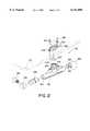
- FIG. 2is a perspective view of the dump valve apparatus of the present invention
- FIG. 3is a sectional view taken through the dump valve apparatus when the foot section of the bed deck is located in a generally horizontal orientation to provide a bed for a patient;
- FIG. 4is a sectional view similar to FIG. 3 illustrating movement of the foot deck section downwardly toward to a generally vertical position and illustrating a piston movable within the dump valve housing to vent the foot cushion air bladder to atmosphere and deflate the foot cushion air bladder;
- FIG. 5is a bottom plan view illustrating the foot cushion air bladder
- FIG. 6is a sectional view taken through the foot cushion air bladder illustrating a contoured profile of a top surface of the air bladder;
- FIG. 7is a sectional view taken through the foot section of FIG. 1 illustrating a foot cushion with a cover installed over the foot air bladder with the deck of the bed in a generally horizontal bed position;
- FIG. 8is a sectional view similar to FIG. 7 illustrating movement of the foot deck section of the bed into a generally vertical chair position in which the foot cushion air bladder is deflated and retracted by an elastic cord in the cover to move the foot surface air bladder toward the deck of the bed.
- FIG. 1illustrates a bariatric bed 10 having a bed frame 12 including castors 14 for moving the bed 10.
- An articulating deck 16is mounted to the frame 12.
- Deck 16includes a foot deck section 18.
- a foot prop 20is pivotably coupled to the foot deck section 18.
- the bedalso includes pivotable siderails 22 on opposite sides of the bed 10.
- the siderails 22are pivotable relative to frame 12 to an outwardly pivoted position in the direction of arrows 24 to accommodate large patients on the bed 10.
- cushionssuch as foam blocks or pillows are wedged between the patient and siderails 22 in order to improve comfort for the patient and to prevent the patient from rubbing against siderails 22.
- the present inventionprovides a low air loss air bladder 26 coupled to each siderail 22 by suitable fasteners such as straps 28.
- Each low air loss bladder 26includes an air inlet connection 30 which is coupled to a blower 32 on bed frame 12 by tubes 34.
- the low air loss air bladdersallow a limited supply of air to escape through at least the inwardly facing surfaces 36 of air bladders 26.
- Low air loss air bladders 26provide improved support and comfort for the patient on the bed 10 and stay in position on the siderails 22.
- the low air loss air bladders 26 adjacent the sides of the patientprovide a cooling air flow to dry perspiration of the patient.
- the bariatric bed 10 of the present inventionincludes a contoured air bladder foot cushion 40.
- the foot cushion 40includes elevated side portions 42 and 44 and an elevated center portion 46 located between the side portions 42 and 44 to define first and second recesses 48 and 50 for receiving first and second legs of a patient.
- the contoured top surface 152 of foot cushion 40holds the legs of the patient spaced apart from each other to reduce chafing.
- the air cushion 40is covered by a cleanable plastic bottom cover 52 having a top zipper 54.
- a top cover 56includes a zipper 58 to connect the top cover 56 to bottom cover 52.
- the top cover 56also includes an elastic cord 60 having a first end coupled to a first side 62 of the top cover 56.
- Cord 60stretches to a top left corner 64 of cover 56 and across the cover to the top right comer 66.
- a second end of cord 60is coupled to cover 56 adjacent zipper 58 on second side 68.
- the elastic cord 60is expanded when foot cushion 40 is inflated. Therefore, when foot cushion 40 is deflated, the cord 60 retracts and draws the cover 56 and the deflated foot cushion 40 inwardly toward a support surface 70 of foot deck section 18.
- the foot deck support surface 70is supported on a bellows 72 which can be inflated and deflated to control the height of the support surface 70 relative to the deck section 18.
- a dump valve 74is connected to support surface 70 to control inflation and deflation of foot surface air cushion 40. It is understood that the foot cushion 40 and dump valve 74 may be used with any articulating deck, with or without the bellows 72.
- Dump valve 74includes as opening 104 connected to foot cushion 40 as discussed below. An inlet of dump valve 74 is coupled to blower 32 by tube 76.
- the dump valve 74includes an elongated cylindrical housing 78 having an interior region 80.
- An L-shaped elbow 82is coupled to outlet end 114 of housing 78 by threads 84.
- An O-ring seal 86is located between the housing 78 and the elbow 82.
- Elbow 82provides a downwardly directed outlet opening to prevent fluids from splashing into dump valve 74.
- a piston 88is located within interior region 80 of housing 78 to open and close the dump valve 74 as discussed in detail below.
- Piston 88is formed from a metal material such as copper or another suitable material having a density great enough for the piston 88 to move within the housing 78 to open and close the dump valve 74.
- piston 88is electroplated with nickel or other suitable material to prevent corrosion and reduce friction of the piston 88 within the housing 78.
- End cap 90is threadably coupled to an inlet end 116 of housing 78.
- End cap 90includes an aperture for receiving an air fitting 92 for coupling the inlet end 116 of the dump valve 74 to the blower 32 with tube 76.
- a top mounting portion of housing 78includes threaded apertures 94 for receiving fasteners 96 to couple the dump valve 74 to a suitable surface such as foot deck support surface 70.
- a mounting plate 98is located above the support surface 70.
- a swivel cap 100is located above mounting plate 98.
- An O-ring seal 102is provided to seal a central opening 104 of housing 78. Swivel plate 100 is used to cover aperture 106 in mounting plate 98 and central opening 104 when the dump valve 74 is not in use.
- the housing 78includes a mounting portion 108 configured to align a longitudinal axis 110 of housing 78 at an angle with respect to a bottom planar surface 112 of support deck surface 70. Therefore, when support surface 70 is in a horizontal bed position of FIG. 3, the longitudinal axis 110 of housing 78 is aligned so that the outlet end 114 of housing 78 is located below inlet end 116. Therefore, piston 88 slides downwardly due to gravity toward outlet end 114 of housing 78 in the direction of arrow 118.
- piston 88permits inlet air from blower 32 to pass through tube 76 and fitting 92 into inlet end 116 of housing 78 in the direction of arrow 120. Piston 88 blocks air flow through the open outlet end 114 of housing 78. Therefore, air moves upwardly in the direction of arrow 122 through opening 104.
- Foot surface section 40includes a connector 124 coupled to a top end of opening 104 and sealed by O-ring 102. Connector 124 includes an internal passageway 126 to permit air flow from opening 104 into air cushion 40 in the direction of arrows 128. Therefore, when the deck 70 is in the generally horizontal position of FIG. 3, the blower 32 supplies air through the dump valve 74 to an interior region of air cushion 40.
- the piston 88is formed to include a helical groove 140.
- the helical groove 140provides an air bearing surface to help the piston 88 slide back and forth within housing 78 without binding.
- the dump valve 74provides a mechanical apparatus for controlling inflation and deflation of the air cushion 40 based on articulation of deck section 70. It is understood that the dump valve 74 may be used with any portion of articulating deck of the bed 10. In addition, the dump valve 74 may be mounted on the opposite side of deck 70 if desired.
- an air bladder coupled to central opening 140is normally deflated when the associated deck section is in the horizontal position. As the deck moves to an angled position, either upwardly or downwardly, the piston 88 slides toward end 116 of housing 78 to permit air to flow into the housing 78 and central aperture to inflate the air bladder.
- This modified configurationmay be useful to selectively inflate a bladder in the seat section of the bed as the bed moves to the chair orientation to reduce the likelihood that the patient will bottom out against the frame of the bed.
- the cushion in the seat or other locationmay be normally deflated or inflated to a certain level until the bed deck articulates to raise the head section or lower the foot section of the deck.
- the piston 88moves downwardly as shown in FIG. 4.
- air inlet hose 76is coupled to end 114 of housing 78 in this modified embodiment, air flows to the air bladder coupled to connector 124. This inflates the air bladder or increases the pressure in a partially inflated bladder.
- the air bladder coupled to dump valve 74may be spaced apart from the connector 124.
- an air supply tubeis used to connect the connector 124 with the remote air bladder.
- FIG. 5illustrates a bottom surface 140 of foot cushion 40.
- a pair of straps 142 and 144are coupled to opposite sides of bottom surface 140.
- a female connector 146is coupled to each strap 142, and a male connector 148 is coupled to each strap 144.
- Aircan be supplied to foot cushion 40 through an opening 150 provided in either side of the foot section bottom surface 140. Only one opening 150 is used at a time. The other opening is sealed.
- the straps 142 and 144wrap around the deck support surface 70 to connect the foot cushion 40 to the support surface 70.
- FIG. 6illustrates the contoured shape of top surface 152.
- Top surface 152 of air cushion 40is formed using a RF welding technique with specially cut baffles to define the elevated side portions 42 and 44 and the elevated central portion 46 which defines first and second recesses 48 and 50 for receiving and separating first and second legs of the patient.
- the contoured foot cushion 40 of the present inventionreduces chafing of the legs which can lead to skin sores.
- FIGS. 7 and 8illustrate the contoured foot cushion 70 covered by bottom cover 52 and top cover 56.
- FIGS. 7 and 8also further illustrate the bellows 72 connected between deck section 18 and foot deck support surface 70. When deck section 18 is in its horizontal bed position, the bellows 72 can be adjusted to control the position of deck support surface 70 and foot cushion 40.
- FIG. 7illustrates that elastic cord 60 extends from a first side 62 upwardly toward the front wall of top cover 56 as also illustrated in FIG. 1.
- Elastic cord 60is stretched when the foot cushion air bladder 40 is inflated during normal operation in the bed position.
- the air bladder 40is deflated by dump valve 74 as discussed above.
- the elastic cord 60 within cover 56retracts as the cushion 40 deflates to gather the cover 56 and the deflated air bladder 40 upwardly over itself and toward the support surface 70. This gathering keeps the deflated foot cushion 40 and cover 56 from falling onto foot prop 20 so that the deflated cushion 40 and cover 56 are out of the way of a patient's feet when the bed is in the chair position.
Landscapes
- Health & Medical Sciences (AREA)
- Nursing (AREA)
- Life Sciences & Earth Sciences (AREA)
- Animal Behavior & Ethology (AREA)
- General Health & Medical Sciences (AREA)
- Public Health (AREA)
- Veterinary Medicine (AREA)
- Invalid Beds And Related Equipment (AREA)
- Mattresses And Other Support Structures For Chairs And Beds (AREA)
Abstract
Description
Claims (21)
Priority Applications (2)
| Application Number | Priority Date | Filing Date | Title |
|---|---|---|---|
| US09/266,959US6141806A (en) | 1997-06-26 | 1999-03-12 | Bariatric bed |
| US09/669,705US6694557B1 (en) | 1997-06-26 | 2000-09-26 | Bariatric bed |
Applications Claiming Priority (2)
| Application Number | Priority Date | Filing Date | Title |
|---|---|---|---|
| US08/883,516US5894966A (en) | 1997-06-26 | 1997-06-26 | Bariatric bed |
| US09/266,959US6141806A (en) | 1997-06-26 | 1999-03-12 | Bariatric bed |
Related Parent Applications (1)
| Application Number | Title | Priority Date | Filing Date |
|---|---|---|---|
| US08/883,516DivisionUS5894966A (en) | 1997-06-26 | 1997-06-26 | Bariatric bed |
Related Child Applications (1)
| Application Number | Title | Priority Date | Filing Date |
|---|---|---|---|
| US09/669,705ContinuationUS6694557B1 (en) | 1997-06-26 | 2000-09-26 | Bariatric bed |
Publications (1)
| Publication Number | Publication Date |
|---|---|
| US6141806Atrue US6141806A (en) | 2000-11-07 |
Family
ID=25382722
Family Applications (2)
| Application Number | Title | Priority Date | Filing Date |
|---|---|---|---|
| US08/883,516Expired - Fee RelatedUS5894966A (en) | 1997-06-26 | 1997-06-26 | Bariatric bed |
| US09/266,959Expired - LifetimeUS6141806A (en) | 1997-06-26 | 1999-03-12 | Bariatric bed |
Family Applications Before (1)
| Application Number | Title | Priority Date | Filing Date |
|---|---|---|---|
| US08/883,516Expired - Fee RelatedUS5894966A (en) | 1997-06-26 | 1997-06-26 | Bariatric bed |
Country Status (7)
| Country | Link |
|---|---|
| US (2) | US5894966A (en) |
| EP (3) | EP1281381A3 (en) |
| JP (1) | JP2002506378A (en) |
| AU (1) | AU8264498A (en) |
| CA (1) | CA2295027A1 (en) |
| DE (1) | DE69814854T2 (en) |
| WO (1) | WO1999000099A2 (en) |
Cited By (49)
| Publication number | Priority date | Publication date | Assignee | Title |
|---|---|---|---|---|
| USD458481S1 (en) | 2001-04-05 | 2002-06-11 | Hill-Rom Services, Inc. | Slats of a bed siderail |
| USD459119S1 (en) | 2001-04-05 | 2002-06-25 | Hill-Rom Services, Inc. | Siderail support arm |
| USD463179S1 (en) | 2001-04-05 | 2002-09-24 | Hill-Rom Services, Inc. | Top rail member of a bed siderail |
| USD479070S1 (en) | 2002-09-06 | 2003-09-02 | Hill-Rom Services, Inc. | Bed siderail |
| US20030167568A1 (en)* | 2001-12-20 | 2003-09-11 | Brooke Jason C. | Bed siderails |
| US6654974B2 (en) | 2000-06-02 | 2003-12-02 | Hill-Rom Services, Inc. | Foot support for a patient support |
| US6678908B2 (en) | 2000-02-07 | 2004-01-20 | Hill-Rom Services, Inc. | Bariatric surface for an operating room table |
| US6739006B2 (en) | 1997-11-07 | 2004-05-25 | Hill-Rom Services, Inc. | Head section support for a surgical table apparatus |
| US6754923B2 (en) | 1997-11-07 | 2004-06-29 | Hill-Rom Services, Inc. | Leg section support for a surgical table |
| US6757924B2 (en) | 1999-08-23 | 2004-07-06 | Hill-Rom Services, Inc. | Bed having a removable foot section |
| US6817363B2 (en) | 2000-07-14 | 2004-11-16 | Hill-Rom Services, Inc. | Pulmonary therapy apparatus |
| US20040250349A1 (en)* | 2003-06-11 | 2004-12-16 | Pierre Rene | Mattress leg rest section for an articulatable bed convertible to a chair position |
| US6862759B2 (en) | 1998-06-26 | 2005-03-08 | Hill-Rom Services, Inc. | Hospital bed |
| US20060085914A1 (en)* | 2004-06-14 | 2006-04-27 | Steve Peterson | Adjustable bed for bariatric patients |
| US20060179576A1 (en)* | 2005-02-17 | 2006-08-17 | Hill-Rom Services, Inc. | Patient helper apparatus |
| US7137160B2 (en) | 1999-04-21 | 2006-11-21 | Hill-Rom Services, Inc. | Proning bed |
| US20080000028A1 (en)* | 2006-06-28 | 2008-01-03 | Stryker Corporation | Patient support |
| US7536734B2 (en) | 2005-01-31 | 2009-05-26 | Hill-Rom Services, Inc. | Birthing support apparatus |
| US7657953B2 (en) | 2005-11-17 | 2010-02-09 | Hill-Rom Services, Inc. | Birthing bed calf support |
| US7676862B2 (en) | 2004-09-13 | 2010-03-16 | Kreg Medical, Inc. | Siderail for hospital bed |
| US7743441B2 (en) | 2004-09-13 | 2010-06-29 | Kreg Therapeutics, Inc. | Expandable width bed |
| US7757318B2 (en) | 2004-09-13 | 2010-07-20 | Kreg Therapeutics, Inc. | Mattress for a hospital bed |
| US7779494B2 (en) | 2004-09-13 | 2010-08-24 | Kreg Therapeutics, Inc. | Bed having fixed length foot deck |
| US20110225740A1 (en)* | 2008-09-10 | 2011-09-22 | Jan Huyser | Angle detection and control |
| US20120172959A1 (en)* | 2011-01-05 | 2012-07-05 | Lachenbruch Charles A | Cooling System for an Occupant of an Occupant Support and a Cooling Garment |
| CN103126839A (en)* | 2011-11-21 | 2013-06-05 | 陈茂寅 | Medical care bed |
| EP2636397A1 (en)* | 2012-03-05 | 2013-09-11 | Hill-Rom Services, Inc. | Articulable bed with a translatable and orientation adjustable deck section and a volumetrically adjustable compensatory element |
| US8595873B2 (en) | 2010-12-08 | 2013-12-03 | Hill-Rom Services, Inc. | Mattress deflation management |
| US8607378B2 (en) | 2010-03-09 | 2013-12-17 | Hill-Rom Services, Inc. | Caregiver assist device |
| US8756735B2 (en) | 2011-02-08 | 2014-06-24 | Hill-Rom Services, Inc. | Patient helper with egress handle |
| USD710509S1 (en) | 2013-09-23 | 2014-08-05 | Hill-Rom Services Pte. Ltd. | Head rail for a patient bed |
| USD710510S1 (en) | 2013-09-23 | 2014-08-05 | Hill-Rom Services Pte. Ltd. | Foot rail for a patient bed |
| USD710507S1 (en) | 2013-09-23 | 2014-08-05 | Hill-Rom Services Pte. Ltd. | Patient bed |
| US8864205B2 (en) | 2006-06-28 | 2014-10-21 | Stryker Corporation | Patient support with wireless data and/or energy transfer |
| US9119753B2 (en) | 2008-06-27 | 2015-09-01 | Kreg Medical, Inc. | Bed with modified foot deck |
| USD768422S1 (en) | 2014-08-12 | 2016-10-11 | Hill-Rom Services, Inc. | Foot end siderail |
| USD769042S1 (en) | 2014-08-12 | 2016-10-18 | Hill-Rom Services, Inc. | Head end siderail |
| USD770829S1 (en) | 2015-01-29 | 2016-11-08 | Hill-Rom Services, Inc. | Head rail for patient bed |
| USD770824S1 (en) | 2014-08-12 | 2016-11-08 | Hill-Rom Services, Inc. | Barrier for a hospital bed |
| USD771259S1 (en) | 2015-01-29 | 2016-11-08 | Hill-Rom Services, Inc. | Foot rail for patient bed |
| US9549865B2 (en) | 2009-09-02 | 2017-01-24 | Allen Medical Systems, Inc. | Surgical positioning system |
| USD804883S1 (en) | 2016-05-28 | 2017-12-12 | Hill-Rom Services, Inc. | Footrail |
| USD804882S1 (en) | 2016-05-28 | 2017-12-12 | Hill-Rom Services, Inc. | Headrail |
| EP3738571A1 (en) | 2019-05-16 | 2020-11-18 | Hill-Rom Services, Inc. | Device for upgrading a residential bed to include an equipment support |
| WO2021127280A1 (en)* | 2019-12-18 | 2021-06-24 | Dabir Surfaces, Inc. | Support surface overlay with vacuum enclosure and method of operation |
| US11052005B2 (en) | 2017-09-19 | 2021-07-06 | Stryker Corporation | Patient support apparatus with handles for patient ambulation |
| US11116680B2 (en) | 2017-09-19 | 2021-09-14 | Stryker Corporation | Patient support apparatus for controlling patient ingress and egress |
| US11160705B2 (en) | 2017-10-20 | 2021-11-02 | Stryker Corporation | Adjustable patient support apparatus for assisted egress and ingress |
| US12150908B2 (en) | 2014-04-18 | 2024-11-26 | Kreg Medical, Inc. | Patient support with stand-up and sit features |
Families Citing this family (12)
| Publication number | Priority date | Publication date | Assignee | Title |
|---|---|---|---|---|
| DK2140847T3 (en) | 2000-11-07 | 2012-08-27 | Tempur World Llc | Therapeutic mattress device |
| USD520783S1 (en) | 2004-10-01 | 2006-05-16 | M.C. Healthcare Products Inc. | Rotating assist rail |
| WO2008032302A1 (en)* | 2006-09-14 | 2008-03-20 | Jacob Hellman | Inflatable-deplatable passive exercise unit |
| US8239986B2 (en) | 2008-03-13 | 2012-08-14 | Hill-Rom Services, Inc. | Siderail assembly for a patient-support apparatus |
| DE102008048501A1 (en)* | 2008-09-23 | 2010-04-01 | Schülke & Mayr GmbH | Valve device for a fluid channel |
| DE102008059997A1 (en)* | 2008-12-02 | 2010-06-10 | GM Global Technology Operations, Inc., Detroit | Motor vehicle seat, has foot rests designed by supporting bodies, and transferred by increasing volume in usage condition, in which foots of occupant is supported at foot rests and by reduction of volume in non-usage condition |
| US8978182B2 (en)* | 2010-09-08 | 2015-03-17 | Hill-Rom Services, Inc. | Occupant protective features for the foot region of a bed |
| US9228885B2 (en) | 2012-06-21 | 2016-01-05 | Hill-Rom Services, Inc. | Patient support systems and methods of use |
| US9456701B2 (en)* | 2014-06-13 | 2016-10-04 | Aeris Technology LLC | Valve assembly for controlling fluid communication between fluid chambers, inflatable device, and method |
| US10017049B2 (en)* | 2015-10-07 | 2018-07-10 | Sikorsky Aircraft Corporation | Vent valve, tank having vent valve, and method |
| CA3085438A1 (en) | 2019-08-13 | 2021-02-13 | Stryker Corporation | Support apparatus for bariatric person |
| US12036162B1 (en)* | 2021-03-31 | 2024-07-16 | Linet Spol. S R.O. | Mechanical pressure control for mattress for use for medical purposes |
Citations (32)
| Publication number | Priority date | Publication date | Assignee | Title |
|---|---|---|---|---|
| US2016054A (en)* | 1934-07-16 | 1935-10-01 | Melvin D Sentell | Pneumatic mattress |
| US3339544A (en)* | 1964-12-11 | 1967-09-05 | Kravitz Harvey | Shaped mattress tor for correcting pedal deformities in children |
| US3656665A (en)* | 1970-04-14 | 1972-04-18 | Kidde & Co Walter | Inertia responsive apparatus for supplying fluid medium under pressure |
| CH602056A5 (en)* | 1976-08-10 | 1978-07-31 | Georg Guggisberg | Leg support to improve blood circulation |
| US4188677A (en)* | 1977-11-30 | 1980-02-19 | Zur Henry C | Lounger bed and adjustable body supporting assembly |
| US4243024A (en)* | 1979-04-02 | 1981-01-06 | The United States Of America As Represented By The Secretary Of The Navy | G-Protection system sensing a change in acceleration and tilt angle |
| US4269213A (en)* | 1978-08-08 | 1981-05-26 | Nissan Motor Company, Limited | Safety valve |
| US4270233A (en)* | 1979-02-15 | 1981-06-02 | Mulligan Jack E | Obstetric bed |
| US4376317A (en)* | 1981-07-06 | 1983-03-15 | Burke, Inc. | Foldable step arrangement for beds |
| US4409695A (en)* | 1981-02-03 | 1983-10-18 | Burke, Inc. | Adjustable bed for morbidly obese patients |
| US4577358A (en)* | 1984-06-11 | 1986-03-25 | Glass Ted A | Bean bag body support |
| US4787104A (en)* | 1984-10-18 | 1988-11-29 | Grantham Frederick W | Convertible hospital bed |
| US4796948A (en)* | 1986-02-14 | 1989-01-10 | Ssi Medical Services, Inc. | Patient support system for wheelchairs and the like |
| US4941221A (en)* | 1986-08-15 | 1990-07-17 | Ian Donald Butcher | Body supporting apparatus |
| WO1990014816A1 (en)* | 1989-05-30 | 1990-12-13 | Mediscus Products Limited | Therapeutic turning bed |
| US5052065A (en)* | 1991-01-08 | 1991-10-01 | West Raymond O | Impact cushioning device for bed or wheelchair |
| US5134739A (en)* | 1989-09-25 | 1992-08-04 | Michel Gaffe | Therapeutic and preventive device for giving a set position to lower limbs |
| US5154185A (en)* | 1990-11-14 | 1992-10-13 | Hartwell Medical Corporation | Air evacuable support |
| US5170364A (en)* | 1990-12-06 | 1992-12-08 | Biomechanics Corporation Of America | Feedback system for load bearing surface |
| GB2267430A (en)* | 1992-06-06 | 1993-12-08 | Mangar Aids Ltd | Lifting apparatus |
| US5394577A (en)* | 1993-03-29 | 1995-03-07 | James; Ingrid B. | Therapeutic anti-decubitus, lateral rotation mattress |
| US5454126A (en)* | 1994-01-25 | 1995-10-03 | Hill-Rom Company, Inc. | Foot egress chair bed |
| US5473313A (en)* | 1993-11-17 | 1995-12-05 | Graebe, Jr.; William F. | Wheelchair seat cushion |
| US5479666A (en)* | 1994-01-25 | 1996-01-02 | Hill-Rom Company, Inc. | Foot egress chair bed |
| US5513899A (en)* | 1991-11-13 | 1996-05-07 | Invacare Corporation | Seat cushion for wheelchairs |
| US5564520A (en)* | 1994-06-20 | 1996-10-15 | Gt Development Corporation | Pneumatic seat rollover vent valve |
| US5579544A (en)* | 1995-06-06 | 1996-12-03 | Attler; Anthony R. | Liftable seat for bathtubs |
| US5603133A (en)* | 1986-09-09 | 1997-02-18 | Kinetic Concepts, Inc. | Apparatus for alternating pressure of a low air loss patient support system |
| US5630238A (en)* | 1995-08-04 | 1997-05-20 | Hill-Rom, Inc. | Bed with a plurality of air therapy devices, having control modules and an electrical communication network |
| US5745939A (en)* | 1996-11-12 | 1998-05-05 | Gaymar Industries, Inc. | Leg rest |
| WO1998022071A1 (en)* | 1996-11-18 | 1998-05-28 | Kinetic Concepts, Inc. | Bariatric treatment system and relating methods |
| US5806115A (en)* | 1992-07-22 | 1998-09-15 | Princeton Products | Portable, integrated, universally adjustable position control system |
Family Cites Families (6)
| Publication number | Priority date | Publication date | Assignee | Title |
|---|---|---|---|---|
| US4215446A (en)* | 1978-08-28 | 1980-08-05 | Patsie Mahoney | Padded hospital bed siderail cover |
| US4309783A (en)* | 1980-02-06 | 1982-01-12 | Teledyne Industries, Inc. | Adjustably conformable bed |
| CH655983A5 (en)* | 1984-03-30 | 1986-05-30 | Inrad Sa | Bistable pneumatic valve |
| CA2113320A1 (en)* | 1993-01-21 | 1994-07-22 | Alan Brian Gancy | Inflatable air mattress and pillow incorporating novel variable tension-response internal structural systems |
| US5450641A (en)* | 1994-06-21 | 1995-09-19 | Connecticut Artcraft Corp | Inflatable bed rail guard |
| GB2326088B (en)* | 1997-06-12 | 2001-09-05 | Michael Anthony Wilkinson | Safesides - inflatable bed sides to prevent injury |
- 1997
- 1997-06-26USUS08/883,516patent/US5894966A/ennot_activeExpired - Fee Related
- 1998
- 1998-06-25CACA002295027Apatent/CA2295027A1/ennot_activeAbandoned
- 1998-06-25EPEP20020079586patent/EP1281381A3/ennot_activeWithdrawn
- 1998-06-25EPEP98932851Apatent/EP0991395B1/ennot_activeExpired - Lifetime
- 1998-06-25AUAU82644/98Apatent/AU8264498A/ennot_activeAbandoned
- 1998-06-25JPJP50570399Apatent/JP2002506378A/enactivePending
- 1998-06-25DEDE69814854Tpatent/DE69814854T2/ennot_activeExpired - Fee Related
- 1998-06-25WOPCT/US1998/013185patent/WO1999000099A2/enactiveIP Right Grant
- 1998-06-25EPEP20020079585patent/EP1281380A3/ennot_activeWithdrawn
- 1999
- 1999-03-12USUS09/266,959patent/US6141806A/ennot_activeExpired - Lifetime
Patent Citations (33)
| Publication number | Priority date | Publication date | Assignee | Title |
|---|---|---|---|---|
| US2016054A (en)* | 1934-07-16 | 1935-10-01 | Melvin D Sentell | Pneumatic mattress |
| US3339544A (en)* | 1964-12-11 | 1967-09-05 | Kravitz Harvey | Shaped mattress tor for correcting pedal deformities in children |
| US3656665A (en)* | 1970-04-14 | 1972-04-18 | Kidde & Co Walter | Inertia responsive apparatus for supplying fluid medium under pressure |
| CH602056A5 (en)* | 1976-08-10 | 1978-07-31 | Georg Guggisberg | Leg support to improve blood circulation |
| US4188677A (en)* | 1977-11-30 | 1980-02-19 | Zur Henry C | Lounger bed and adjustable body supporting assembly |
| US4269213A (en)* | 1978-08-08 | 1981-05-26 | Nissan Motor Company, Limited | Safety valve |
| US4270233A (en)* | 1979-02-15 | 1981-06-02 | Mulligan Jack E | Obstetric bed |
| US4243024A (en)* | 1979-04-02 | 1981-01-06 | The United States Of America As Represented By The Secretary Of The Navy | G-Protection system sensing a change in acceleration and tilt angle |
| US4409695A (en)* | 1981-02-03 | 1983-10-18 | Burke, Inc. | Adjustable bed for morbidly obese patients |
| US4376317A (en)* | 1981-07-06 | 1983-03-15 | Burke, Inc. | Foldable step arrangement for beds |
| US4577358A (en)* | 1984-06-11 | 1986-03-25 | Glass Ted A | Bean bag body support |
| US4787104A (en)* | 1984-10-18 | 1988-11-29 | Grantham Frederick W | Convertible hospital bed |
| US4796948A (en)* | 1986-02-14 | 1989-01-10 | Ssi Medical Services, Inc. | Patient support system for wheelchairs and the like |
| US4941221A (en)* | 1986-08-15 | 1990-07-17 | Ian Donald Butcher | Body supporting apparatus |
| US5603133A (en)* | 1986-09-09 | 1997-02-18 | Kinetic Concepts, Inc. | Apparatus for alternating pressure of a low air loss patient support system |
| WO1990014816A1 (en)* | 1989-05-30 | 1990-12-13 | Mediscus Products Limited | Therapeutic turning bed |
| US5134739A (en)* | 1989-09-25 | 1992-08-04 | Michel Gaffe | Therapeutic and preventive device for giving a set position to lower limbs |
| US5154185A (en)* | 1990-11-14 | 1992-10-13 | Hartwell Medical Corporation | Air evacuable support |
| US5170364A (en)* | 1990-12-06 | 1992-12-08 | Biomechanics Corporation Of America | Feedback system for load bearing surface |
| US5052065A (en)* | 1991-01-08 | 1991-10-01 | West Raymond O | Impact cushioning device for bed or wheelchair |
| US5513899A (en)* | 1991-11-13 | 1996-05-07 | Invacare Corporation | Seat cushion for wheelchairs |
| US5408710A (en)* | 1992-06-06 | 1995-04-25 | Mangars International Limited | Lifting apparatus |
| GB2267430A (en)* | 1992-06-06 | 1993-12-08 | Mangar Aids Ltd | Lifting apparatus |
| US5806115A (en)* | 1992-07-22 | 1998-09-15 | Princeton Products | Portable, integrated, universally adjustable position control system |
| US5394577A (en)* | 1993-03-29 | 1995-03-07 | James; Ingrid B. | Therapeutic anti-decubitus, lateral rotation mattress |
| US5473313A (en)* | 1993-11-17 | 1995-12-05 | Graebe, Jr.; William F. | Wheelchair seat cushion |
| US5454126A (en)* | 1994-01-25 | 1995-10-03 | Hill-Rom Company, Inc. | Foot egress chair bed |
| US5479666A (en)* | 1994-01-25 | 1996-01-02 | Hill-Rom Company, Inc. | Foot egress chair bed |
| US5564520A (en)* | 1994-06-20 | 1996-10-15 | Gt Development Corporation | Pneumatic seat rollover vent valve |
| US5579544A (en)* | 1995-06-06 | 1996-12-03 | Attler; Anthony R. | Liftable seat for bathtubs |
| US5630238A (en)* | 1995-08-04 | 1997-05-20 | Hill-Rom, Inc. | Bed with a plurality of air therapy devices, having control modules and an electrical communication network |
| US5745939A (en)* | 1996-11-12 | 1998-05-05 | Gaymar Industries, Inc. | Leg rest |
| WO1998022071A1 (en)* | 1996-11-18 | 1998-05-28 | Kinetic Concepts, Inc. | Bariatric treatment system and relating methods |
Cited By (91)
| Publication number | Priority date | Publication date | Assignee | Title |
|---|---|---|---|---|
| US6739006B2 (en) | 1997-11-07 | 2004-05-25 | Hill-Rom Services, Inc. | Head section support for a surgical table apparatus |
| US6754923B2 (en) | 1997-11-07 | 2004-06-29 | Hill-Rom Services, Inc. | Leg section support for a surgical table |
| US6862759B2 (en) | 1998-06-26 | 2005-03-08 | Hill-Rom Services, Inc. | Hospital bed |
| US7137160B2 (en) | 1999-04-21 | 2006-11-21 | Hill-Rom Services, Inc. | Proning bed |
| US7464421B2 (en) | 1999-08-23 | 2008-12-16 | Hill-Rom Services, Inc. | Bed having a removable foot section |
| US7073221B2 (en) | 1999-08-23 | 2006-07-11 | Hill-Rom Services, Inc. | Bed having a removable foot section |
| US6757924B2 (en) | 1999-08-23 | 2004-07-06 | Hill-Rom Services, Inc. | Bed having a removable foot section |
| US6678908B2 (en) | 2000-02-07 | 2004-01-20 | Hill-Rom Services, Inc. | Bariatric surface for an operating room table |
| US6854145B2 (en) | 2000-06-02 | 2005-02-15 | Hill-Rom Services, Inc. | Patient support |
| US6654974B2 (en) | 2000-06-02 | 2003-12-02 | Hill-Rom Services, Inc. | Foot support for a patient support |
| US7469433B2 (en) | 2000-06-02 | 2008-12-30 | Hill-Rom Services, Inc. | Patient support with variable length actuator and release mechanism for lowering a sectional support surface |
| US6857153B2 (en) | 2000-06-02 | 2005-02-22 | Hill-Rom Services, Inc. | Patient support having a light assembly |
| US6817363B2 (en) | 2000-07-14 | 2004-11-16 | Hill-Rom Services, Inc. | Pulmonary therapy apparatus |
| US7931607B2 (en) | 2000-07-14 | 2011-04-26 | Hill-Rom Services, Inc. | Pulmonary therapy apparatus |
| US7343916B2 (en) | 2000-07-14 | 2008-03-18 | Hill-Rom Services, Inc. | Pulmonary therapy apparatus |
| USD458481S1 (en) | 2001-04-05 | 2002-06-11 | Hill-Rom Services, Inc. | Slats of a bed siderail |
| USD463179S1 (en) | 2001-04-05 | 2002-09-24 | Hill-Rom Services, Inc. | Top rail member of a bed siderail |
| USD459119S1 (en) | 2001-04-05 | 2002-06-25 | Hill-Rom Services, Inc. | Siderail support arm |
| US20030167568A1 (en)* | 2001-12-20 | 2003-09-11 | Brooke Jason C. | Bed siderails |
| USD479070S1 (en) | 2002-09-06 | 2003-09-02 | Hill-Rom Services, Inc. | Bed siderail |
| US20040250349A1 (en)* | 2003-06-11 | 2004-12-16 | Pierre Rene | Mattress leg rest section for an articulatable bed convertible to a chair position |
| US6910236B2 (en) | 2003-06-11 | 2005-06-28 | Rene Pierre | Mattress leg rest section for an articulatable bed convertible to a chair position |
| US20060085914A1 (en)* | 2004-06-14 | 2006-04-27 | Steve Peterson | Adjustable bed for bariatric patients |
| US7757318B2 (en) | 2004-09-13 | 2010-07-20 | Kreg Therapeutics, Inc. | Mattress for a hospital bed |
| US7779494B2 (en) | 2004-09-13 | 2010-08-24 | Kreg Therapeutics, Inc. | Bed having fixed length foot deck |
| US7676862B2 (en) | 2004-09-13 | 2010-03-16 | Kreg Medical, Inc. | Siderail for hospital bed |
| US8069514B2 (en) | 2004-09-13 | 2011-12-06 | Kreg Medical, Inc. | Expandable width bed |
| US7743441B2 (en) | 2004-09-13 | 2010-06-29 | Kreg Therapeutics, Inc. | Expandable width bed |
| US8056160B2 (en) | 2004-09-13 | 2011-11-15 | Kreg Medical, Inc. | Siderail for hospital bed |
| US7536734B2 (en) | 2005-01-31 | 2009-05-26 | Hill-Rom Services, Inc. | Birthing support apparatus |
| US7536738B2 (en) | 2005-02-17 | 2009-05-26 | Hill-Rom Services, Inc. | Patient helper apparatus |
| US20060179576A1 (en)* | 2005-02-17 | 2006-08-17 | Hill-Rom Services, Inc. | Patient helper apparatus |
| US8327480B2 (en) | 2005-11-17 | 2012-12-11 | Hill-Rom Services, Inc. | Birthing bed lift off foot section |
| US8640287B2 (en) | 2005-11-17 | 2014-02-04 | Hill-Rom Services, Inc. | Patient-support apparatus with a locking deck section |
| US7757317B2 (en) | 2005-11-17 | 2010-07-20 | Hill-Rom Services, Inc. | Stowing birthing bed foot section |
| US7657953B2 (en) | 2005-11-17 | 2010-02-09 | Hill-Rom Services, Inc. | Birthing bed calf support |
| US7669259B2 (en) | 2005-11-17 | 2010-03-02 | Hill-Rom Services, Inc. | Stowing birthing bed foot section |
| US8117697B2 (en) | 2005-11-17 | 2012-02-21 | Hill-Rom Services, Inc. | Patient-support apparatus with a locking deck section |
| US7676868B2 (en) | 2005-11-17 | 2010-03-16 | Hill-Rom Services, Inc. | Birthing bed foot support release handle |
| US8079101B2 (en) | 2005-11-17 | 2011-12-20 | Hill-Rom Services, Inc. | Over-molded limb support |
| US20080000028A1 (en)* | 2006-06-28 | 2008-01-03 | Stryker Corporation | Patient support |
| US8056163B2 (en) | 2006-06-28 | 2011-11-15 | Stryker Corporation | Patient support |
| US10561551B2 (en) | 2006-06-28 | 2020-02-18 | Stryker Corporation | Patient support with energy transfer |
| US8864205B2 (en) | 2006-06-28 | 2014-10-21 | Stryker Corporation | Patient support with wireless data and/or energy transfer |
| US12383450B2 (en) | 2006-06-28 | 2025-08-12 | Stryker Corporation | Patient support with energy transfer |
| US11793699B2 (en) | 2006-06-28 | 2023-10-24 | Stryker Corporation | Patient support with energy transfer |
| US9119753B2 (en) | 2008-06-27 | 2015-09-01 | Kreg Medical, Inc. | Bed with modified foot deck |
| US12208041B2 (en) | 2008-06-27 | 2025-01-28 | Kreg Medical, Inc. | Bed with frame assembly |
| US10617582B2 (en) | 2008-06-27 | 2020-04-14 | Kreg Medical, Inc. | Bed with modified foot deck |
| US20110225740A1 (en)* | 2008-09-10 | 2011-09-22 | Jan Huyser | Angle detection and control |
| US8914928B2 (en)* | 2008-09-10 | 2014-12-23 | Huntleigh Technology Limited | Angle detection and control |
| US10391014B2 (en) | 2009-09-02 | 2019-08-27 | Allen Medical Systems, Inc. | Surgical positioning system |
| US9549865B2 (en) | 2009-09-02 | 2017-01-24 | Allen Medical Systems, Inc. | Surgical positioning system |
| US9333138B2 (en) | 2010-03-09 | 2016-05-10 | Hill-Rom Services, Inc. | Hospital bed having patient lifting device |
| US8607378B2 (en) | 2010-03-09 | 2013-12-17 | Hill-Rom Services, Inc. | Caregiver assist device |
| US8595873B2 (en) | 2010-12-08 | 2013-12-03 | Hill-Rom Services, Inc. | Mattress deflation management |
| US9277827B2 (en) | 2010-12-08 | 2016-03-08 | Hill-Rom Services, Inc. | Mattress deflation management |
| US20120172959A1 (en)* | 2011-01-05 | 2012-07-05 | Lachenbruch Charles A | Cooling System for an Occupant of an Occupant Support and a Cooling Garment |
| US10010446B2 (en)* | 2011-01-05 | 2018-07-03 | Hill-Rom Services, Inc. | Cooling system for an occupant of an occupant support and a cooling garment |
| US8756735B2 (en) | 2011-02-08 | 2014-06-24 | Hill-Rom Services, Inc. | Patient helper with egress handle |
| US9585804B2 (en) | 2011-02-08 | 2017-03-07 | Hill-Rom Services, Inc. | Accessory frame attachment apparatus |
| CN103126839A (en)* | 2011-11-21 | 2013-06-05 | 陈茂寅 | Medical care bed |
| US9009895B2 (en) | 2012-03-05 | 2015-04-21 | Hill-Rom Services, Inc. | Articulable bed with a translatable and orientation adjustable deck section and volumetrically adjustable compensatory element |
| EP2636397A1 (en)* | 2012-03-05 | 2013-09-11 | Hill-Rom Services, Inc. | Articulable bed with a translatable and orientation adjustable deck section and a volumetrically adjustable compensatory element |
| USD710509S1 (en) | 2013-09-23 | 2014-08-05 | Hill-Rom Services Pte. Ltd. | Head rail for a patient bed |
| USD710510S1 (en) | 2013-09-23 | 2014-08-05 | Hill-Rom Services Pte. Ltd. | Foot rail for a patient bed |
| USD710507S1 (en) | 2013-09-23 | 2014-08-05 | Hill-Rom Services Pte. Ltd. | Patient bed |
| US12239594B2 (en) | 2014-04-18 | 2025-03-04 | Kreg Medical, Inc. | Patient support with stand-up and sit features |
| US12239593B2 (en) | 2014-04-18 | 2025-03-04 | Kreg Medical, Inc. | Patient support with stand-up and sit features |
| US12150908B2 (en) | 2014-04-18 | 2024-11-26 | Kreg Medical, Inc. | Patient support with stand-up and sit features |
| USD819382S1 (en) | 2014-08-12 | 2018-06-05 | Hill-Rom Services, Inc. | Head end siderail |
| USD769042S1 (en) | 2014-08-12 | 2016-10-18 | Hill-Rom Services, Inc. | Head end siderail |
| USD770824S1 (en) | 2014-08-12 | 2016-11-08 | Hill-Rom Services, Inc. | Barrier for a hospital bed |
| USD825973S1 (en) | 2014-08-12 | 2018-08-21 | Hill-Rom Services, Inc. | Barrier for a hospital bed |
| USD768422S1 (en) | 2014-08-12 | 2016-10-11 | Hill-Rom Services, Inc. | Foot end siderail |
| USD817682S1 (en) | 2014-08-12 | 2018-05-15 | Hill-Rom Services, Inc. | Foot end siderail |
| USD817058S1 (en) | 2015-01-29 | 2018-05-08 | Hill-Rom Services, Inc. | Head rail for patient bed |
| USD770829S1 (en) | 2015-01-29 | 2016-11-08 | Hill-Rom Services, Inc. | Head rail for patient bed |
| USD771259S1 (en) | 2015-01-29 | 2016-11-08 | Hill-Rom Services, Inc. | Foot rail for patient bed |
| USD855369S1 (en) | 2015-01-29 | 2019-08-06 | Hill-Rom Services, Inc. | Foot rail for patient bed |
| USD858166S1 (en) | 2016-05-28 | 2019-09-03 | Hill-Rom Services, Inc. | Headrail |
| USD850836S1 (en) | 2016-05-28 | 2019-06-11 | Hill-Rom Services, Inc. | Footrail |
| USD804883S1 (en) | 2016-05-28 | 2017-12-12 | Hill-Rom Services, Inc. | Footrail |
| USD804882S1 (en) | 2016-05-28 | 2017-12-12 | Hill-Rom Services, Inc. | Headrail |
| US11052005B2 (en) | 2017-09-19 | 2021-07-06 | Stryker Corporation | Patient support apparatus with handles for patient ambulation |
| US11723821B2 (en) | 2017-09-19 | 2023-08-15 | Stryker Corporation | Patient support apparatus for controlling patient ingress and egress |
| US11116680B2 (en) | 2017-09-19 | 2021-09-14 | Stryker Corporation | Patient support apparatus for controlling patient ingress and egress |
| US11806290B2 (en) | 2017-10-20 | 2023-11-07 | Stryker Corporation | Adjustable patient support apparatus for assisted egress and ingress |
| US11160705B2 (en) | 2017-10-20 | 2021-11-02 | Stryker Corporation | Adjustable patient support apparatus for assisted egress and ingress |
| EP3738571A1 (en) | 2019-05-16 | 2020-11-18 | Hill-Rom Services, Inc. | Device for upgrading a residential bed to include an equipment support |
| WO2021127280A1 (en)* | 2019-12-18 | 2021-06-24 | Dabir Surfaces, Inc. | Support surface overlay with vacuum enclosure and method of operation |
Also Published As
| Publication number | Publication date |
|---|---|
| EP1281380A3 (en) | 2004-01-21 |
| WO1999000099A3 (en) | 1999-03-18 |
| DE69814854T2 (en) | 2004-05-06 |
| EP1281381A3 (en) | 2003-05-21 |
| AU8264498A (en) | 1999-01-19 |
| US5894966A (en) | 1999-04-20 |
| JP2002506378A (en) | 2002-02-26 |
| EP0991395B1 (en) | 2003-05-21 |
| EP0991395A2 (en) | 2000-04-12 |
| CA2295027A1 (en) | 1999-01-07 |
| WO1999000099A2 (en) | 1999-01-07 |
| EP1281380A2 (en) | 2003-02-05 |
| EP1281381A2 (en) | 2003-02-05 |
| DE69814854D1 (en) | 2003-06-26 |
Similar Documents
| Publication | Publication Date | Title |
|---|---|---|
| US6141806A (en) | Bariatric bed | |
| US6694557B1 (en) | Bariatric bed | |
| US6295675B1 (en) | Mattress assembly | |
| US7523515B2 (en) | Hospital bed and mattress having a retractable foot section | |
| US6739005B2 (en) | Bed with adjustable elevation components | |
| USRE43155E1 (en) | Hospital bed and mattress having a retractable foot section | |
| US5956787A (en) | Anti-decubitus pneumatic mattress | |
| US5647079A (en) | Inflatable patient support surface system | |
| US8844075B2 (en) | Footboard with partial mattress integration | |
| US5913774A (en) | Hospital bed mattress with an adjustable firmness perineal end section | |
| US6282735B1 (en) | Hydrotherapy bed | |
| CA2520743C (en) | Hospital bed having an adjustable length deck | |
| MXPA00001937A (en) | Mattress assembly | |
| CA2202222A1 (en) | Portable orthopedic bed |
Legal Events
| Date | Code | Title | Description |
|---|---|---|---|
| STCF | Information on status: patent grant | Free format text:PATENTED CASE | |
| AS | Assignment | Owner name:HILL-ROM SERVICES, INC., INDIANA Free format text:ASSIGNMENT OF ASSIGNORS INTEREST;ASSIGNOR:HILL-ROM, INC.;REEL/FRAME:011796/0440 Effective date:20010215 | |
| FPAY | Fee payment | Year of fee payment:4 | |
| FEPP | Fee payment procedure | Free format text:PAYER NUMBER DE-ASSIGNED (ORIGINAL EVENT CODE: RMPN); ENTITY STATUS OF PATENT OWNER: LARGE ENTITY Free format text:PAYOR NUMBER ASSIGNED (ORIGINAL EVENT CODE: ASPN); ENTITY STATUS OF PATENT OWNER: LARGE ENTITY | |
| FPAY | Fee payment | Year of fee payment:8 | |
| FPAY | Fee payment | Year of fee payment:12 | |
| AS | Assignment | Owner name:JPMORGAN CHASE BANK, N.A., AS COLLATERAL AGENT, ILLINOIS Free format text:SECURITY INTEREST;ASSIGNORS:ALLEN MEDICAL SYSTEMS, INC.;HILL-ROM SERVICES, INC.;ASPEN SURGICAL PRODUCTS, INC.;AND OTHERS;REEL/FRAME:036582/0123 Effective date:20150908 Owner name:JPMORGAN CHASE BANK, N.A., AS COLLATERAL AGENT, IL Free format text:SECURITY INTEREST;ASSIGNORS:ALLEN MEDICAL SYSTEMS, INC.;HILL-ROM SERVICES, INC.;ASPEN SURGICAL PRODUCTS, INC.;AND OTHERS;REEL/FRAME:036582/0123 Effective date:20150908 | |
| AS | Assignment | Owner name:JPMORGAN CHASE BANK, N.A., AS COLLATERAL AGENT, ILLINOIS Free format text:SECURITY AGREEMENT;ASSIGNORS:HILL-ROM SERVICES, INC.;ASPEN SURGICAL PRODUCTS, INC.;ALLEN MEDICAL SYSTEMS, INC.;AND OTHERS;REEL/FRAME:040145/0445 Effective date:20160921 Owner name:JPMORGAN CHASE BANK, N.A., AS COLLATERAL AGENT, IL Free format text:SECURITY AGREEMENT;ASSIGNORS:HILL-ROM SERVICES, INC.;ASPEN SURGICAL PRODUCTS, INC.;ALLEN MEDICAL SYSTEMS, INC.;AND OTHERS;REEL/FRAME:040145/0445 Effective date:20160921 | |
| AS | Assignment | Owner name:HILL-ROM COMPANY, INC., ILLINOIS Free format text:RELEASE BY SECURED PARTY;ASSIGNOR:JPMORGAN CHASE BANK, N.A.;REEL/FRAME:050254/0513 Effective date:20190830 Owner name:WELCH ALLYN, INC., NEW YORK Free format text:RELEASE BY SECURED PARTY;ASSIGNOR:JPMORGAN CHASE BANK, N.A.;REEL/FRAME:050254/0513 Effective date:20190830 Owner name:VOALTE, INC., FLORIDA Free format text:RELEASE BY SECURED PARTY;ASSIGNOR:JPMORGAN CHASE BANK, N.A.;REEL/FRAME:050254/0513 Effective date:20190830 Owner name:MORTARA INSTRUMENT, INC., WISCONSIN Free format text:RELEASE BY SECURED PARTY;ASSIGNOR:JPMORGAN CHASE BANK, N.A.;REEL/FRAME:050254/0513 Effective date:20190830 Owner name:ALLEN MEDICAL SYSTEMS, INC., ILLINOIS Free format text:RELEASE BY SECURED PARTY;ASSIGNOR:JPMORGAN CHASE BANK, N.A.;REEL/FRAME:050254/0513 Effective date:20190830 Owner name:HILL-ROM, INC., ILLINOIS Free format text:RELEASE BY SECURED PARTY;ASSIGNOR:JPMORGAN CHASE BANK, N.A.;REEL/FRAME:050254/0513 Effective date:20190830 Owner name:HILL-ROM SERVICES, INC., ILLINOIS Free format text:RELEASE BY SECURED PARTY;ASSIGNOR:JPMORGAN CHASE BANK, N.A.;REEL/FRAME:050254/0513 Effective date:20190830 Owner name:MORTARA INSTRUMENT SERVICES, INC., WISCONSIN Free format text:RELEASE BY SECURED PARTY;ASSIGNOR:JPMORGAN CHASE BANK, N.A.;REEL/FRAME:050254/0513 Effective date:20190830 Owner name:ANODYNE MEDICAL DEVICE, INC., FLORIDA Free format text:RELEASE BY SECURED PARTY;ASSIGNOR:JPMORGAN CHASE BANK, N.A.;REEL/FRAME:050254/0513 Effective date:20190830 |