US6141593A - Cardiac lead with ETEE coated DBS coil - Google Patents
Cardiac lead with ETEE coated DBS coilDownload PDFInfo
- Publication number
- US6141593A US6141593AUS09/189,031US18903198AUS6141593AUS 6141593 AUS6141593 AUS 6141593AUS 18903198 AUS18903198 AUS 18903198AUS 6141593 AUS6141593 AUS 6141593A
- Authority
- US
- United States
- Prior art keywords
- insulating sleeve
- loop
- conductor wire
- flexible insulating
- loops
- Prior art date
- Legal status (The legal status is an assumption and is not a legal conclusion. Google has not performed a legal analysis and makes no representation as to the accuracy of the status listed.)
- Expired - Lifetime
Links
Images


Classifications
- H—ELECTRICITY
- H01—ELECTRIC ELEMENTS
- H01R—ELECTRICALLY-CONDUCTIVE CONNECTIONS; STRUCTURAL ASSOCIATIONS OF A PLURALITY OF MUTUALLY-INSULATED ELECTRICAL CONNECTING ELEMENTS; COUPLING DEVICES; CURRENT COLLECTORS
- H01R4/00—Electrically-conductive connections between two or more conductive members in direct contact, i.e. touching one another; Means for effecting or maintaining such contact; Electrically-conductive connections having two or more spaced connecting locations for conductors and using contact members penetrating insulation
- H01R4/56—Electrically-conductive connections between two or more conductive members in direct contact, i.e. touching one another; Means for effecting or maintaining such contact; Electrically-conductive connections having two or more spaced connecting locations for conductors and using contact members penetrating insulation one conductor screwing into another
- A—HUMAN NECESSITIES
- A61—MEDICAL OR VETERINARY SCIENCE; HYGIENE
- A61N—ELECTROTHERAPY; MAGNETOTHERAPY; RADIATION THERAPY; ULTRASOUND THERAPY
- A61N1/00—Electrotherapy; Circuits therefor
- A61N1/02—Details
- A61N1/04—Electrodes
- A61N1/05—Electrodes for implantation or insertion into the body, e.g. heart electrode
- A61N1/056—Transvascular endocardial electrode systems
- H—ELECTRICITY
- H01—ELECTRIC ELEMENTS
- H01R—ELECTRICALLY-CONDUCTIVE CONNECTIONS; STRUCTURAL ASSOCIATIONS OF A PLURALITY OF MUTUALLY-INSULATED ELECTRICAL CONNECTING ELEMENTS; COUPLING DEVICES; CURRENT COLLECTORS
- H01R2201/00—Connectors or connections adapted for particular applications
- H01R2201/12—Connectors or connections adapted for particular applications for medicine and surgery
Definitions
- This inventionrelates generally to cardiac stimulator leads, and more particularly to a cardiac stimulator lead having an improved structure for joining the ends of two conductor wires.
- Conventional cardiac stimulator systemsconsist of a cardiac stimulator and an elongated flexible cardiac lead that is connected proximally to a header structure on the cardiac stimulator and is implanted distally at one or more sites within the heart requiring cardiac stimulation or sensing.
- the cardiac stimulatoris normally a pacemaker, a cardioverter/defibrillator, a sensing instrument, or some combination of these devices.
- the distal end of a cardiac leadis inserted through an incision in the chest and manipulated by the physician to the site requiring electrical stimulation with the aid of a flexible stylet that is removed prior to closure.
- the distal end of the leadis anchored to the endocardium by an active mechanism, such as a screw-in electrode tip, or alternatively, by a passive mechanism, such as one or more radially spaced tines that engage the endocardium.
- an active mechanismsuch as a screw-in electrode tip
- a passive mechanismsuch as one or more radially spaced tines that engage the endocardium.
- the proximal end of the leadis then connected to the cardiac stimulator and the incision is closed.
- the implantation route and siteare usually imaged in real time by fluoroscopy to confirm proper manipulation and placement of the lead.
- a conventional cardiac stimulator leadnormally consists of an elongated, flexible, tubular, electrically insulating sleeve that is connected proximally to a connector that is adapted to couple to the header of a cardiac stimulator.
- pacing leadsthe distal end of the insulating sleeve is joined with a tip electrode.
- a defibrillator or shock coilcommonly projects from the distal end of the insulating sleeve.
- the shock coilconsists of an uninsulated coiled wire wound with a large number of coils. The plurality of coils distribute defibrillation pulses over a much larger surface area of the myocardium than a pacing electrode.
- the electrical pathway between the lead connector and the shock coilis provided by a separate conductor wire that is coupled proximally to the connector and secured distally to a crimp assembly.
- the conventional crimp assemblyconsists of an inner tubular sleeve over which respective ends of the shock coil and the other conductor wire are positioned and crimped into position by respective outer crimp sleeves.
- the inner sleeve and the outer sleevesare normally made of titanium or other relatively rigid biocompatible conducting materials.
- the inner tubular sleeveis of such length that the ends of the shock coil and the other wire are usually not intertwined. The conducting nature of the inner sleeve is relied upon to pass current between the two wires.
- a conventional crimp assemblycan significantly hamper the movement of a stylet used to spatially manipulate the lead during implantation.
- the physicianinserts a stylet into the lead connector and advances it to the distal tip of the lead.
- the physicianthen manipulates the stylet to accurately position the distal end of the lead proximate the endocardial site requiring electrical stimulation.
- the distal end of the styletmust be inserted through the crimp assembly in order to reach the tip of the lead. This step may not be problematic where the stylet is not bent significantly prior to insertion, as is often the case where the implantation involves a relatively straight pathway through the heart. Fixation to the right ventricular apex is an example of such a relatively straight pathway.
- fixation to the superior interventricular septum or access to the great cardiac vein via the coronary sinusrequire the lead tip to be turned abruptly after entry into the heart. This is frequently accomplished by introducing a severe bend in the distal end of the lead, usually after the lead is initially positioned inside the heart. Initially, a straight stylet is used to move the lead into the right atrium. Then the straight stylet is removed and a highly curved stylet is inserted and advanced to the distal end of the lead. The stylet is usually curved by the physician by hand based on the physician's experience and knowledge of the patient's particular anatomy. The radius of curvature of the bend may be quite small.
- the initial movement of the highly curved portion of the stylet through the leadmay be unremarkable since the majority of the lead is quite flexible.
- the leadAs the curved portion is advanced, the lead is able to temporarily conform to the curvature of the stylet.
- the crimp assemblyIn contrast to the insulating sleeve, the crimp assembly is quite rigid and cannot conform to the curvature of the stylet.
- the physicianmay encounter significant resistance to further axial movement when the highly curved portion of the stylet encounters the inner sleeve. This undesirable tactile response is more than just a nuisance.
- the natural tendency of the physician at this pointis to apply additional thrust to the proximal end of the stylet to force the curved portion through the inner sleeve.
- the styletis highly curved and thrust is being applied at the opposite end thereof, the stylet will tend to behave like an unstable column under compression loading. If the rubbing of the inner sleeve is great enough, axial thrust applied by the physician will cause the stylet to buckle and plastically deform at one or more points along its length. With one or more unintended bends in the stylet, the movement of the lead in response to manipulation of the stylet may be unpredictable and the complexity of the implantation procedure increased.
- the present inventionis directed to overcoming or reducing the effects of one or more of the foregoing disadvantages.
- a cardiac leadin accordance with one aspect of the present invention, includes a connector for coupling to a cardiac stimulator and a first flexible insulating sleeve coupled to the connector.
- a second flexible insulating sleeveis coupled to the connector and has a portion positioned inside the first flexible insulating sleeve.
- a first coiled conductor wireis provided that has at least a first loop and a second loop. The first and second loops are positioned between the second flexible insulating sleeve and the first insulating sleeve.
- a second conductor wireis provided that has at least a third loop. The third loop is positioned between the second flexible insulating sleeve and the first insulating sleeve. The first and second conductor wires are spiraled together so that the third loop is positioned between the first and second loops.
- a cardiac leadin accordance with another aspect of the present invention, includes a first connector and a second connector coupled to a branch assembly.
- a first flexible insulating sleeveis coupled to the branch assembly.
- a second flexible insulating sleeveis coupled to the branch assembly and has a portion positioned inside the first flexible insulating sleeve.
- a first coiled conductor wireis provided that has at least a first loop and a second loop. The first and second loops are positioned around the second flexible insulating sleeve within the branch assembly.
- a second conductor wireis provided that has a third loop. The first and second conductor wires are spiraled together so that the third loop is positioned between the first and second loops.
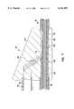
- FIG. 1is a pictorial view of a conventional cardiac stimulator lead
- FIG. 2is a cross-sectional view of FIG. 1 taken at section 2--2;
- FIG. 3is a cross-sectional view of FIG. 1 taken at section 3--3;
- FIG. 4is a quarter-sectional anterior view of a human heart depicting a typical implantation of the lead shown in FIGS. 1-3;
- FIG. 5is a side view of the proximal end of the lead of FIG. 1 depicting insertion of a curved stylet
- FIG. 6is pictorial view of an exemplary embodiment of a cardiac lead and a cardiac stimulator in accordance with the present invention
- FIG. 7is a cross-sectional view of FIG. 6 taken at section 7--7 in accordance with the present invention.
- FIG. 8is a cross-sectional view of FIG. 6 taken at section 8--8 in accordance with the present invention.
- FIG. 9is a cross-sectional view of one of the filars of a conductor wire of the lead shown in FIGS. 6 and 7 in accordance with the present invention.
- FIG. 10is a side view of an exemplary embodiment of a wire coil spreader in accordance with the present invention.
- FIG. 11is a cross-sectional view of the coil spreader shown in FIG. 10 in accordance with the present invention.
- FIG. 12is a side view like FIG. 10 showing a conductor wire positioned thereon prior to coil spreading in accordance with the present invention.
- FIG. 13is a view like FIG. 12 depicting the wire after coil spreading in accordance with the present invention.
- FIGS. 14 and 15are side views of two conductor wires of the lead of FIG. 6 depicting the process of intertwining of the two wires.
- FIGS. 1 and 2there is shown an exemplary conventional pacing/defibrillator lead 10 (hereinafter "lead 10").
- the lead 10is provided with a flexible tubular insulating sleeve 12 that divides proximally into segments 14 and 16 at a branch 18.
- the segment 14terminates proximally in a connector 20 and the segment 16 terminates proximally in another connector 22.
- the connectors 20 and 22are designed to be inserted into a cardiac pacemaker can (not shown).
- the connector 20terminates proximally in a pin 24.
- the pin 24is connected to a conductor wire positioned inside the segment 14 and the lead sleeve 12 as described more fully below.
- a set of O-rings 25is molded to the exterior of the connector 20 to retard the intrusion of body fluids into the pacemaker can.
- the connector 22similarly terminates in a connector pin 26.
- the pin 26is hollow to enable insertion of a stylet inside the lead 10 during implantation.
- the connector pin 26is connected to a conductor wire that is positioned in the segment and stretches to the branch 18 as described more fully below.
- An annular contact 27is fitted to the connector 22. Pairs of O-rings 28 and 29 are molded to the exterior of the connector 22 to provide a seal against body fluids entering the pacemaker.
- the distal end of the insulating sleeve 12encloses a crimp assembly 30.
- a defibrillator or shock coil 31projects distally from the crimp assembly 30, terminating inside a tip sleeve 32.
- a tip electrode 34projects slightly from the tip sleeve 32 and is provided with a corkscrew 35 for securing the lead 10 to myocardial tissue.
- the tip electrode 34is connected to a conductor wire 36 that extends through the length of the lead 10, terminating at and connecting with the pin 26.
- the conductor wire 36is jacketed by an insulating sleeve 37 that is secured distally to tip electrode 34 by a biocompatible medical grade adhesive and proximally over the connector pin 26 in a like manner.
- a suture sleeve 38is slipped over the sleeve 12.
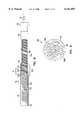
- the detailed structure of the crimp assembly 30may be understood by referring now to FIG. 2, which is a cross-sectional view of FIG. 1 taken at section 2--2.
- the crimp assembly 30includes an inner crimp sleeve 39 that is positioned inside the insulating sleeve 12.
- Two outer crimp sleeves 40 and 42are crimped around the inner crimp sleeve 39.
- the outer crimp sleeve 40secures the distal end of a conductor wire 44 to the inner crimp sleeve 39.
- the outer crimp sleeve 42secures the proximal end of the shock coil 31 to the inner crimp sleeve 39.
- the inner crimp sleeve 39is typically composed of a conducting material, such as titanium, that establishes an electrical pathway between the distal end of the conducting wire 44 and the proximal end of the shock coil 31.
- Another conductor wire 36passes through the inner crimp sleeve 39 and is connected proximally to the connector pin 26 of the connector 22 shown in FIG. 1, and distally to the tip electrode 34 shown in FIG. 1.
- the shock coil 31is disposed around a shock coil sleeve 48.
- One end 49 of the shock coil sleeve 48is slipped over the distal end of the inner crimp sleeve 39. The other end is secured to the proximal end of the tip electrode 34 shown in FIG. 1.
- the insulating sleeve 12is slipped around the exterior of the inner crimp sleeve 39 and of the outer crimp sleeves 40 and 42, and secured with medical adhesive.
- the small gap between the inner diameter of the insulating sleeve 12 and the outer diameter of the shock coil sleeve 48is sealed with a biocompatible adhesive 50.
- the conductor wire 44is individually insulated, save the portion thereof positioned between the outer crimp sleeve 40 and the inner crimp sleeve 39 so that electrical isolation is maintained between the conductor wire 44 and the conductor wire 36 throughout the length of the insulating sleeve 12.
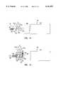
- FIG. 3is a cross sectional view of FIG. 1 taken at section 3--3.
- the branch 18includes a branch body 52 that is slipped over and glued around the segment 14, the segment 16 and the insulating sleeve 12 as shown.
- a crimp assembly 54is positioned inside the branch body 52 and is structurally identical to the crimp assembly 30 depicted in FIG. 2. Accordingly, the crimp assembly 54 includes outer crimp sleeves 56 and 58 positioned around an inner crimp sleeve 60.
- the conductor wire 44is crimped to the inner crimp sleeve 56 by the outer crimp sleeve 58.
- the conductor wire 44Proximal to the outer crimp sleeve 58, the conductor wire 44 is uncoiled and routed through the branch body 52 and into the segment 14.
- the uncoiled filars 62 of the conductor wire 40are shown in phantom.
- the distal end of a conductor wire 64is crimped to the inner crimp sleeve 60 by the outer crimp sleeve 56.
- the conductor wire 64is connected proximally to the annular electrode 27 of the connector 22 shown in FIG. 1. Note that the conductor wire 64 and the conductor wire 44 are electrically connected via the conducting inner crimp sleeve 60.
- the conductor wire 36passes through the branch body 52 and the inner crimp sleeve 60 and into a tubular sleeve 66 that is positioned inside the segment 16 and extends proximally past the proximal end of the annular electrode 27.
- FIG. 4is a quarter-sectional anterior view of a human heart 68.
- the lead sleeve 12is introduced into the superior cava 70, and advanced through the right atrium 72 into the right ventricle 74 via the tricuspid valve 76.
- the corkscrew 35 of the lead 10is secured superiorly to the interventricular septum 78 and a sufficient portion of the lead sleeve 12 is advanced into the right ventricle 74 so that the shock coil 31 is brought into physical engagement with the interventricular septum 78.
- a significant bend 80must be introduced into the lead 10.
- Bends in the lead 10, such as the bend 80,are common in implantation procedures involving deviated pathways, such as the pathway depicted in FIG. 4, as well as pathways leading to fixation to the right hand side of the right atrium 68 or pathways involving entry into the coronary sinus 82.
- the lead 10is spatially manipulated by means of a flexible stylet 84 that is inserted into the connector pin 26 of the connector 22 and advanced inside the lead 10 to the tip assembly 32.
- the stylet 84is of such length that it is shown broken.
- a small cylindrical handle 85is fitted to the stylet 84 to aid the physician in applying thrust to the stylet 84, particularly when a majority of the length of the stylet 84 is already inserted into the lead 10.
- the distal end 86 of the stylet 84is plastically deformed by hand into a highly curved shape prior to insertion into the pin 26 as shown in FIG. 5. The bending action establishes a relatively small radius of the curvature r for the distal end 86.
- the tight bend of the distal end 86 combined with the internal structure of the lead 10can create difficulties for the physician at the time of implantation.
- the distal end 86 of the stylet 84is advanced through the connector 22, the segment 16, and into the branch assembly 18, the generally tubular structure of the connector 22 and the inner sleeve 66 will tend to temporarily and partially straighten the distal end 86.
- the distal end 86will retain a significant curved portion 88 as shown in FIG. 3.
- this highly curved portion 88passes through the inner crimp sleeve 60, significant rubbing and frictional resistance to longitudinal movement will result. Since the inner crimp sleeve 60 is composed of a relatively rigid material, it cannot temporarily deform to more easily permit the curved portion 88 to pass therethrough.
- the resistance to longitudinal movement of the distal end 86 of the stylet 84 through the crimp assembly 54is normally overcome by applying additional thrust to the portion of the stylet 84 projecting from the connector pin 26 without undue effort.
- the passage of the distal end 86 through the crimp assembly 30is more problematic.
- FIG. 2as the curved portion 88 of the distal end 86 passes through the crimp assembly 30, the aforementioned rubbing action occurs.
- the resistance to longitudinal movement of the stylet 84is now compounded by friction between the stylet 84 and the internal structures of the sleeve 10 proximal to the crimp assembly 30. At this point, the stylet 84 behaves much like an unstable column under compressive load.
- the stylet 84will have a tendency to buckle and permanently deform at one or more places between the handle 85 and the highly curved portion 88. These new bends in the stylet 84 can make the behavior of the stylet 84 and the movement of the lead 10 thereby somewhat unpredictable for the physician.
- FIGS. 6, 7 and 8are sectional views of FIG. 6 taken, respectively, at sections 7--7 and 8--8. For clarity of illustration, certain components of the lead 90 are shown in full in FIG. 8.
- the cardiac stimulator lead 90includes a lead body 92 that has a tubular insulating sleeve 94 which bifurcates proximally into two segments 96 and 98 at a branch assembly 100. The length of the lead body 92 is such that it is shown broken.
- a suture sleeve 101is slipped over and used to secure the lead body 92 at a preselected point in the patient's body.
- the segment 96terminates in a connector 102 and the segment 98 terminates in a connector 104.
- the connector 102is provided with a connector pin 106 and the connector 104 is provided with a connector pin 108 and an annular contact 110.
- the connectors 102 and 104are designed to be connected to a cardiac stimulator 112, which consists of a can 114 and a header assembly 116 coupled to the can 114.
- the header assembly 116includes ports 118 and 119 into which the connectors 102 and 104 are inserted respectively.
- the connectors 102 and 104are shown highly exaggerated in size relative to the remainder of the lead 90 for clarity of illustration.
- the cardiac stimulator 112may be a pacemaker, a cardioverter/defibrillator, a sensing instrument, or a combination of these functionalities.
- the pin 106is connected via by crimping, welding or the like to a conductor wire 120 that passes through the segment 96 and the branch assembly 100 and extends into the lead sleeve 94 as described more fully below.
- the conductor wire 120is preferably coiled and comprises a plurality of adjacent loops.
- the conductor 120may be comprised of one or more filars, each filar lying adjacent the others.
- a set of O-rings 121is molded to the exterior of the connector 102 to retard the intrusion of body fluids into the cardiac stimulator header 116.
- the pin 108is hollow to enable insertion of a stylet inside the lead 90 during implantation.
- the connector pin 108is connected via by crimping, welding or the like to a conductor wire 122 that passes through the segment 98 and terminates in the branch assembly 100 as described more fully below.
- the conductor wire 122is preferably coiled and comprises a plurality of adjacent loops.
- the conductormay be comprised of one or more filars, each filar lying adjacent the others. Pairs of O-rings 123 and 124 are molded to the exterior of the connector 104 to retard body fluid intrusion.
- the exterior of the connectors 102 and 104may be composed of a biocompatible electrically insulating material, such as silicone, polyurethane or the like, and the pins 106 and 108 may be fabricated from stainless steel, titanium or the like.
- a defibrillator or shock coil 126projects distally from the distal end 127 of the insulating sleeve 94, terminating inside a tip sleeve 128.
- the proximal end of the shock coil 126is intertwined proximally with the distal end of the conductor wire 120 at the region designated 129.
- the conductor wire 120is connected proximally to the connector pin 106 shown in FIG. 6 by crimping, welding or the like.
- the shock coil 126delivers defibrillating pulses from the cardiac stimulator 112 to myocardial tissue.
- a tip electrode 130projects slightly from the tip sleeve 128 and is provided with a corkscrew 132.
- the corkscrew 132is used to secure the tip electrode 130 to myocardial tissue, and may be augmented and/or substituted with one or more radially spaced tines or other type of fixation mechanism.
- the tip electrode 130supplies pacing pulses from the cardiac stimulator 112 to myocardial tissue and transmits sensing signals from myocardial tissue back to the cardiac stimulator 112.
- An electrical pathway between the tip electrode 130 and the connector pin 108is established by a conductor wire 133 that is connected distally to the tip electrode 130 by biocompatible medical grade adhesive, crimping, welding or the like, and extends through the length of the lead 90, terminating at and connecting to the pin 108 by like methods.
- Both the conductor wire 120 and the shock coil 126are positioned around an inner sleeve 134 that is coupled distally to the tip electrode 130 inside the tip sleeve 128 by biocompatible medical grade adhesive, crimping or like methods, and proximally to the connector 104 shown in FIG. 6 by like methods. Note that a portion of the inner sleeve 134 is cut away to reveal the conductor wire 133 positioned therein. The conductor wire 133 is disposed inside the inner sleeve 134.
- the inner sleeve 134is designed to take most if not all of any tensile load applied to the lead body 92, and to electrically insulate the conductor wire 133 from the conductor wires 120 and the 126.
- the insulating sleeve 94is designed to provide a flexible protective shroud for the conductor wire 120 and the portion of the shock coil 126 connected to the conductor wire 120.
- the segments 96 and 98 of the sleeve 94provide structurally robust physical connections between the connectors 102 and 104 and the branch assembly 100.
- the insulating sleeve 94is advantageously a flexible tubular structure composed of a biocompatible material, such as silicone, polyurethane or the like.
- the insulating sleeve 94is composed of silicone.
- the inner sleeve 134 and the tip sleeve 128may be similarly composed. While flexibility is a desired characteristic for both the insulating sleeve 94 and the inner sleeve 134, it is not necessarily a prerequisite for the tip sleeve 128.
- the tip electrode 130may be fabricated from a variety of biocompatible conducting materials, such as iridium oxide coated titanium, MP35N alloy, stainless steel, platinum-iridium alloy consisting of approximately 90% platinum and 10% iridium, or some other biocompatible conducting metal, or a semiconductor material, such as silicon, or other semiconductor material.
- biocompatible conducting materialssuch as iridium oxide coated titanium, MP35N alloy, stainless steel, platinum-iridium alloy consisting of approximately 90% platinum and 10% iridium, or some other biocompatible conducting metal, or a semiconductor material, such as silicon, or other semiconductor material.
- the detailed structure of the conductor wire 120may be understood by referring now also to FIG. 9, which is a cross sectional view of one of the filars of the wire 120.
- the conductor wire 120is a four-filar coiled wire, with each filar consisting of a conductor 135A individually coated with an insulating jacket 135B.
- the conductor 135Amay include a plurality of filaments 136 as shown or a single filament.
- the conductor 135Amay be composed of a variety of biocompatible conducting materials, such as MP35N alloy, stainless steel, titanium or like materials.
- the conductor 135Ais composed of drawn-brazed strands ("DBS") or filaments 136 of stainless steel.
- DBSdrawn-brazed strands
- the insulating coating 135Bmay be composed of a variety of biocompatible insulating materials, such as ETFE (fluoropolymer resin) or like materials.
- ETFEfluoropolymer resin
- another form of conductor wiremay be used, such as, for example, a single filar insulated or uninsulated wire.
- the shock coil 126is a three-filar coiled wire.
- the filarsmay be composed of a variety of biocompatible conducting materials, such as MP35N alloy, stainless steel, titanium or like materials.
- the filarsare composed of iridium oxide coated titanium. Iridium oxide provides excellent resistance to corrosion caused by body fluids.
- the shock coil 126may take on another form, such as, for example, a six filar wire.
- the inner sleeve 134provides the structural member necessary to take tensile loads applied to the lead body 92. Accordingly, the connection between the conductor wire 120 and the shock coil 126 may be established without crimping or an assembly like the conventional crimp assembly 30 shown in FIG. 2. In this regard, the conductor wire 120 may be reliably secured to the shock coil 126 by intertwining at least one of the loops 137 of the conductor wire 120 and at least one of the loops 138 of the shock coil 126 as shown in FIG. 8.
- the intertwining of the loops 137 of the four-filar conductor wire 120 and the loops 138 of the tri-filar shock coil 126is accomplished by plastically deforming a portion of the conductor wire 120 prior to assembly.
- the nominal or undeformed pitch P 0 between adjacent loopsis shown in FIG. 8.
- the goal of the plastic deformation processis expand the pitch of at least adjacent loops, in this case the loops 137 and 139, from the undeformed pitch P 0 to the expanded pitch P 1 .
- the expanded pitch P 1enables the coil 138 of the shock coil 126 to, in essence, be screwed together with the loops 137 and 139 of the conductor wire 120 so that the loop 138 is positioned between the loops 137 and 139.
- the deformation of the conductor wire 120 to achieve the desired pitch P 1 of the sets of loops 137 and 139may be accomplished using a coil spreader 144, an exemplary embodiment of which is depicted in FIGS. 10 and 11.
- FIG. 10is a side view of the coil spreader 144
- FIG. 11is a sectional view of the coil spreader 144.
- the coil spreader 144includes a mandrel 146 that is secured to a handle 148.
- the distal end 150 of the mandrel 146is provided with a set of external threads or grooves 150 that are cut or otherwise formed in the mandrel 146 with a pitch direction, that is, left handed or right handed, that matches the pitch direction of the conductor wire 120.
- the grooves 150are also formed with pitch P T , and are helical and square.
- the width W R of each rootis equal to the diameter of the filars multiplied by the number of filars in the coil.
- the width of each crest W Cis equal to P T -W R .
- the pitch P Tis related to the ultimately desired pitch P 1 of loops of the conductor wire 120 according to the expression:
- Xis the anticipated elastic recovery of the conductor wire 120 following removal from the mandrel 146.
- the distal end 149 of the mandrel 146is provided with an outer diameter that is just slightly less than the inner diameter of the conductor wire 120 to enable the conductor wire 120 to be readily slipped over the distal end 149.
- the proximal end 152 of the mandrel 146is positioned in a bore 154 in the handle 148 and secured thereto by a set screw 156.
- a collar 158is positioned over the mandrel via in internal bore 159 and is provided with a set screw 160 that is designed to engage the conductor wire 120 as described below.
- FIGS. 12 and 13are side views like FIG. 10 prior to and during the engagement of the threads 150 by the conductor wire 120.
- the conductor wire 120is slipped over the mandrel 146.
- the conductor wire 120has a nominal pitch P 0 defined generally by the spacing between the first filar of loop and a point on the first filar the next adjacent loop of the coil.
- the threads 150are formed with a pitch P T and are helical and square so that the width of the root of each thread is W R and the width of each crest is P T -W R .
- the collar 158is slipped over the threads 150 and the set screw 160 is tightened until it bottoms out on the mandrel 146.
- the collar 158prevents the coils 137 and 139 from slipping out of the grooves 150 during advancement through the threads 150.
- the conductor wire 120is advanced until the distal end of the conductor wire 120 engages the threads 150. At this point, the conductor wire 120 is rotated, according to the pitch direction of the threads 150, in this case counterclockwise. As the conductor wire 120 is rotated, the adjacent loops 137 and 139 are spread apart by the threads 150 and plastically deformed to assume a new pitch.
- the conductor wire 120may be rotated until the end thereof abuts the side of the set screw 160.
- the collar 158is rotated to unscrew the coils 137 and 139 from the threads 150.
- the set screw 160pushes against the end of the loop 137 to unscrew the wire 120 from the mandrel 146.
- the set screw 160may be loosened slightly to enable free rotation of the collar 158.
- the plastic deformation of the loops 137 and 139is almost instantaneous.
- the conductor wire 120may be spiraled off the mandrel 146 without delay.
- FIGS. 14 and 15are, respectively, side views of the conductor wire 120 and the shock coil 126 during and after assembly.
- the conductor wire 120is slipped over the left end 162 of a mandrel 164 and the shock coil 126 is slipped over the right end 166 of the mandrel 164 and moved into contact with the conductor wire 120.
- the conductor wire 120 and shock coil 126are then intertwined by rotating either the conductor wire 120 or the shock coil 126 or both so that the loops 137 and 139 of the wire 120 and the loop 138 of the shock coil 126 screw together as shown.
- the mandrel 164will be removed and replaced with the inner sleeve 134. This transition may be eased by first slipping the proximal end 172 of the inner sleeve 134 over the distal end 166 of the mandrel 164. Then, by pulling the mandrel in the direction of the arrows 173, the inner sleeve 134 will automatically slide inside the shock coil 126 and the conductor wire 120. Note that the inner sleeve 134 is of such length that it is shown broken and that the outer diameter of the proximal end 172 thereof is shown exaggerated in size relative to the distal end 166 of the mandrel 164. FIG.
- FIG. 15shows the inner sleeve 134 after being pulled inside the shock coil 126 and the conductor wire 138.
- the distal end 166 of the mandrelmay be disconnected from the proximal end 172 of the inner sleeve 134.
- Electrical contact between the conductor wire 120 and the shock coil 126takes place through physical contact of adjacent filars where the two coils are threaded together. This contact may be enhanced by encasing this area in a conductive adhesive such as gold or silver impregnated epoxy, silicon or an elastomeric polymer.
- the branch assembly 100includes a branch body 174 that is slipped over and glued around the segments 96 and 98 and the insulating sleeve 94 with a biocompatible medical grade adhesive.
- the branch body 174is designed to provide a biocompatible, electrically insulating and readily moldable junction structure. Accordingly, the branch body 174 may be composed of a variety of biocompatible moldable insulating materials, such as silicone, polyurethane, or the like.
- the wires 120 and 122are connected to enable bipolar pacing. Pacing pulses generated by the cardiac stimulator 112 are transmitted to the tip electrode 130 (see FIGS. 6 and 8) via the connector pin 108 and the conductor wire 133. Return pulses from myocardial tissue during pacing are routed back to the cardiac stimulator 1 12 through the annular contact 110 (see FIG. 6). The pathway for return pulses from myocardial tissue back to the annular contact 110 is through the shock coil 126, the conductor wire 120, and finally the conductor wire 122.
- the conductor wire 122may take on a variety of configurations, such as single filar, multi-filar or the like and may be composed of the same types of materials used to fabricate the conductor wire 120. In an exemplary embodiment, the wire 122 is an uncoated, coiled three-filar wire composed of drawn brazed strands of stainless steel MP35N steel.
- the engagement between the conductor wire 122 and the conductor wire 120 inside the branch body 174is substantially identical to the configuration depicted in FIG. 8.
- the loops of the conductor wire 120are spread as described above in conjunction with FIGS. 12 and 13 so that the loops of the tri-filar conductor wire 122 may be intertwined therewith at 176 and 178.
- the conductor wire 120is unfurled proximal to the coil of the wire 122 at 176 and positioned in longitudinal alignment with the segment 96. The unfurling establishes arcuate sections 180 of the filars in the branch body 174 that are shown in phantom.
- the lead body of the present invention incorporating intertwined conductor wires 120 and 126 spiraled around the flexible inner sleeve 134essentially eliminates rigid tubing through which the implanting physician might otherwise have to traverse a stylet during implantation of a conventional lead.
- the flexibility of the entire length of the lead body 92means that the lead body 92 will more easily conform to the curvature of the stylet. The result is less resistance to passage of the stylet, less potential for buckling of the stylet, and a better tactile response for the physician.
- FIGS. 6, 7 and 8The foregoing illustrated embodiments included the union of a shock coil 126 and a conductor wire 120 (see FIGS. 6, 7 and 8).
- the skilled artisanwill appreciate the combination of the inner sleeve 134 and the intertwining of coils may be used to join a myriad of different types of conductor wires, either in a branched lead as shown, or in a lead incorporating a single insulating lead sleeve.
- the loops of one of the wiresmay be spread as shown or the loops of both may be spread prior to intertwining as desired.
Landscapes
- Health & Medical Sciences (AREA)
- Heart & Thoracic Surgery (AREA)
- Vascular Medicine (AREA)
- Cardiology (AREA)
- Engineering & Computer Science (AREA)
- Biomedical Technology (AREA)
- Nuclear Medicine, Radiotherapy & Molecular Imaging (AREA)
- Radiology & Medical Imaging (AREA)
- Life Sciences & Earth Sciences (AREA)
- Animal Behavior & Ethology (AREA)
- General Health & Medical Sciences (AREA)
- Public Health (AREA)
- Veterinary Medicine (AREA)
- Electrotherapy Devices (AREA)
Abstract
Description
1. Field of the Invention
This invention relates generally to cardiac stimulator leads, and more particularly to a cardiac stimulator lead having an improved structure for joining the ends of two conductor wires.
2. Description of the Related Art
Conventional cardiac stimulator systems consist of a cardiac stimulator and an elongated flexible cardiac lead that is connected proximally to a header structure on the cardiac stimulator and is implanted distally at one or more sites within the heart requiring cardiac stimulation or sensing. The cardiac stimulator is normally a pacemaker, a cardioverter/defibrillator, a sensing instrument, or some combination of these devices. At the time of implantation, the distal end of a cardiac lead is inserted through an incision in the chest and manipulated by the physician to the site requiring electrical stimulation with the aid of a flexible stylet that is removed prior to closure. At the site requiring electrical stimulation, the distal end of the lead is anchored to the endocardium by an active mechanism, such as a screw-in electrode tip, or alternatively, by a passive mechanism, such as one or more radially spaced tines that engage the endocardium. The proximal end of the lead is then connected to the cardiac stimulator and the incision is closed. The implantation route and site are usually imaged in real time by fluoroscopy to confirm proper manipulation and placement of the lead.
A conventional cardiac stimulator lead normally consists of an elongated, flexible, tubular, electrically insulating sleeve that is connected proximally to a connector that is adapted to couple to the header of a cardiac stimulator. In pacing leads, the distal end of the insulating sleeve is joined with a tip electrode. In defibrillator leads, a defibrillator or shock coil commonly projects from the distal end of the insulating sleeve. The shock coil consists of an uninsulated coiled wire wound with a large number of coils. The plurality of coils distribute defibrillation pulses over a much larger surface area of the myocardium than a pacing electrode.
In some conventional defibrillator lead designs, the electrical pathway between the lead connector and the shock coil is provided by a separate conductor wire that is coupled proximally to the connector and secured distally to a crimp assembly. The conventional crimp assembly consists of an inner tubular sleeve over which respective ends of the shock coil and the other conductor wire are positioned and crimped into position by respective outer crimp sleeves. The inner sleeve and the outer sleeves are normally made of titanium or other relatively rigid biocompatible conducting materials. The inner tubular sleeve is of such length that the ends of the shock coil and the other wire are usually not intertwined. The conducting nature of the inner sleeve is relied upon to pass current between the two wires.
A conventional crimp assembly can significantly hamper the movement of a stylet used to spatially manipulate the lead during implantation. For most implantation procedures, the physician inserts a stylet into the lead connector and advances it to the distal tip of the lead. The physician then manipulates the stylet to accurately position the distal end of the lead proximate the endocardial site requiring electrical stimulation. The distal end of the stylet must be inserted through the crimp assembly in order to reach the tip of the lead. This step may not be problematic where the stylet is not bent significantly prior to insertion, as is often the case where the implantation involves a relatively straight pathway through the heart. Fixation to the right ventricular apex is an example of such a relatively straight pathway.
Where the implantation requires the pathway of the lead tip to be deviated, the situation may become more difficult for the physician. For example, fixation to the superior interventricular septum or access to the great cardiac vein via the coronary sinus require the lead tip to be turned abruptly after entry into the heart. This is frequently accomplished by introducing a severe bend in the distal end of the lead, usually after the lead is initially positioned inside the heart. Initially, a straight stylet is used to move the lead into the right atrium. Then the straight stylet is removed and a highly curved stylet is inserted and advanced to the distal end of the lead. The stylet is usually curved by the physician by hand based on the physician's experience and knowledge of the patient's particular anatomy. The radius of curvature of the bend may be quite small.
The initial movement of the highly curved portion of the stylet through the lead may be unremarkable since the majority of the lead is quite flexible. As the curved portion is advanced, the lead is able to temporarily conform to the curvature of the stylet. In contrast to the insulating sleeve, the crimp assembly is quite rigid and cannot conform to the curvature of the stylet. As a result, the physician may encounter significant resistance to further axial movement when the highly curved portion of the stylet encounters the inner sleeve. This undesirable tactile response is more than just a nuisance. The natural tendency of the physician at this point is to apply additional thrust to the proximal end of the stylet to force the curved portion through the inner sleeve. Because the stylet is highly curved and thrust is being applied at the opposite end thereof, the stylet will tend to behave like an unstable column under compression loading. If the rubbing of the inner sleeve is great enough, axial thrust applied by the physician will cause the stylet to buckle and plastically deform at one or more points along its length. With one or more unintended bends in the stylet, the movement of the lead in response to manipulation of the stylet may be unpredictable and the complexity of the implantation procedure increased.
The present invention is directed to overcoming or reducing the effects of one or more of the foregoing disadvantages.
In accordance with one aspect of the present invention, a cardiac lead is provided that includes a connector for coupling to a cardiac stimulator and a first flexible insulating sleeve coupled to the connector. A second flexible insulating sleeve is coupled to the connector and has a portion positioned inside the first flexible insulating sleeve. A first coiled conductor wire is provided that has at least a first loop and a second loop. The first and second loops are positioned between the second flexible insulating sleeve and the first insulating sleeve. A second conductor wire is provided that has at least a third loop. The third loop is positioned between the second flexible insulating sleeve and the first insulating sleeve. The first and second conductor wires are spiraled together so that the third loop is positioned between the first and second loops.
In accordance with another aspect of the present invention, a cardiac lead is provided that includes a first connector and a second connector coupled to a branch assembly. A first flexible insulating sleeve is coupled to the branch assembly. A second flexible insulating sleeve is coupled to the branch assembly and has a portion positioned inside the first flexible insulating sleeve. A first coiled conductor wire is provided that has at least a first loop and a second loop. The first and second loops are positioned around the second flexible insulating sleeve within the branch assembly. A second conductor wire is provided that has a third loop. The first and second conductor wires are spiraled together so that the third loop is positioned between the first and second loops.
The foregoing and other advantages of the invention will become apparent upon reading the following detailed description and upon reference to the drawings in which:
FIG. 1 is a pictorial view of a conventional cardiac stimulator lead;
FIG. 2 is a cross-sectional view of FIG. 1 taken atsection 2--2;
FIG. 3 is a cross-sectional view of FIG. 1 taken atsection 3--3;
FIG. 4 is a quarter-sectional anterior view of a human heart depicting a typical implantation of the lead shown in FIGS. 1-3;
FIG. 5 is a side view of the proximal end of the lead of FIG. 1 depicting insertion of a curved stylet;
FIG. 6 is pictorial view of an exemplary embodiment of a cardiac lead and a cardiac stimulator in accordance with the present invention;
FIG. 7 is a cross-sectional view of FIG. 6 taken at section 7--7 in accordance with the present invention;
FIG. 8 is a cross-sectional view of FIG. 6 taken atsection 8--8 in accordance with the present invention;
FIG. 9 is a cross-sectional view of one of the filars of a conductor wire of the lead shown in FIGS. 6 and 7 in accordance with the present invention;
FIG. 10 is a side view of an exemplary embodiment of a wire coil spreader in accordance with the present invention;
FIG. 11 is a cross-sectional view of the coil spreader shown in FIG. 10 in accordance with the present invention;
FIG. 12 is a side view like FIG. 10 showing a conductor wire positioned thereon prior to coil spreading in accordance with the present invention; and
FIG. 13 is a view like FIG. 12 depicting the wire after coil spreading in accordance with the present invention; and
FIGS. 14 and 15 are side views of two conductor wires of the lead of FIG. 6 depicting the process of intertwining of the two wires.
Background Art
Turning now to the drawings, and in particular to FIGS. 1 and 2 there is shown an exemplary conventional pacing/defibrillator lead 10 (hereinafter "lead 10"). Thelead 10 is provided with a flexible tubular insulatingsleeve 12 that divides proximally intosegments branch 18. Thesegment 14 terminates proximally in aconnector 20 and thesegment 16 terminates proximally in anotherconnector 22. Theconnectors connector 20 terminates proximally in apin 24. Thepin 24 is connected to a conductor wire positioned inside thesegment 14 and thelead sleeve 12 as described more fully below. A set of O-rings 25 is molded to the exterior of theconnector 20 to retard the intrusion of body fluids into the pacemaker can. Theconnector 22 similarly terminates in aconnector pin 26. However, thepin 26 is hollow to enable insertion of a stylet inside thelead 10 during implantation. Theconnector pin 26 is connected to a conductor wire that is positioned in the segment and stretches to thebranch 18 as described more fully below. Anannular contact 27 is fitted to theconnector 22. Pairs of O-rings connector 22 to provide a seal against body fluids entering the pacemaker.
The distal end of the insulatingsleeve 12 encloses acrimp assembly 30. A defibrillator orshock coil 31 projects distally from thecrimp assembly 30, terminating inside atip sleeve 32. Atip electrode 34 projects slightly from thetip sleeve 32 and is provided with acorkscrew 35 for securing thelead 10 to myocardial tissue. Thetip electrode 34 is connected to aconductor wire 36 that extends through the length of thelead 10, terminating at and connecting with thepin 26. Theconductor wire 36 is jacketed by an insulatingsleeve 37 that is secured distally to tipelectrode 34 by a biocompatible medical grade adhesive and proximally over theconnector pin 26 in a like manner. Asuture sleeve 38 is slipped over thesleeve 12.
The detailed structure of thecrimp assembly 30 may be understood by referring now to FIG. 2, which is a cross-sectional view of FIG. 1 taken atsection 2--2. Thecrimp assembly 30 includes aninner crimp sleeve 39 that is positioned inside the insulatingsleeve 12. Twoouter crimp sleeves inner crimp sleeve 39. Theouter crimp sleeve 40 secures the distal end of aconductor wire 44 to theinner crimp sleeve 39. Similarly, theouter crimp sleeve 42 secures the proximal end of theshock coil 31 to theinner crimp sleeve 39. Theinner crimp sleeve 39 is typically composed of a conducting material, such as titanium, that establishes an electrical pathway between the distal end of theconducting wire 44 and the proximal end of theshock coil 31. Anotherconductor wire 36 passes through theinner crimp sleeve 39 and is connected proximally to theconnector pin 26 of theconnector 22 shown in FIG. 1, and distally to thetip electrode 34 shown in FIG. 1. Theshock coil 31 is disposed around ashock coil sleeve 48. Oneend 49 of theshock coil sleeve 48 is slipped over the distal end of theinner crimp sleeve 39. The other end is secured to the proximal end of thetip electrode 34 shown in FIG. 1.
The insulatingsleeve 12 is slipped around the exterior of theinner crimp sleeve 39 and of theouter crimp sleeves sleeve 12 and the outer diameter of theshock coil sleeve 48 is sealed with abiocompatible adhesive 50. Theconductor wire 44 is individually insulated, save the portion thereof positioned between theouter crimp sleeve 40 and theinner crimp sleeve 39 so that electrical isolation is maintained between theconductor wire 44 and theconductor wire 36 throughout the length of the insulatingsleeve 12.
The detailed structure of thebranch 18 may be understood by referring now to FIG. 3, which is a cross sectional view of FIG. 1 taken atsection 3--3. Thebranch 18 includes abranch body 52 that is slipped over and glued around thesegment 14, thesegment 16 and the insulatingsleeve 12 as shown. Acrimp assembly 54 is positioned inside thebranch body 52 and is structurally identical to thecrimp assembly 30 depicted in FIG. 2. Accordingly, thecrimp assembly 54 includesouter crimp sleeves inner crimp sleeve 60. Theconductor wire 44 is crimped to theinner crimp sleeve 56 by theouter crimp sleeve 58. Proximal to theouter crimp sleeve 58, theconductor wire 44 is uncoiled and routed through thebranch body 52 and into thesegment 14. The uncoiled filars 62 of theconductor wire 40 are shown in phantom. The distal end of aconductor wire 64 is crimped to theinner crimp sleeve 60 by theouter crimp sleeve 56. Theconductor wire 64 is connected proximally to theannular electrode 27 of theconnector 22 shown in FIG. 1. Note that theconductor wire 64 and theconductor wire 44 are electrically connected via the conductinginner crimp sleeve 60. Theconductor wire 36 passes through thebranch body 52 and theinner crimp sleeve 60 and into atubular sleeve 66 that is positioned inside thesegment 16 and extends proximally past the proximal end of theannular electrode 27.
An illustrative implantation of thelead 10 may be understood by referring now to FIGS. 4 and 5. FIG. 4 is a quarter-sectional anterior view of ahuman heart 68. Thelead sleeve 12 is introduced into thesuperior cava 70, and advanced through theright atrium 72 into theright ventricle 74 via thetricuspid valve 76. Thecorkscrew 35 of thelead 10 is secured superiorly to theinterventricular septum 78 and a sufficient portion of thelead sleeve 12 is advanced into theright ventricle 74 so that theshock coil 31 is brought into physical engagement with theinterventricular septum 78. In order to establish the requisite engagement with the superiorinterventricular septum 78, asignificant bend 80 must be introduced into thelead 10. Bends in thelead 10, such as thebend 80, are common in implantation procedures involving deviated pathways, such as the pathway depicted in FIG. 4, as well as pathways leading to fixation to the right hand side of theright atrium 68 or pathways involving entry into thecoronary sinus 82.
Thelead 10 is spatially manipulated by means of aflexible stylet 84 that is inserted into theconnector pin 26 of theconnector 22 and advanced inside thelead 10 to thetip assembly 32. Thestylet 84 is of such length that it is shown broken. A smallcylindrical handle 85 is fitted to thestylet 84 to aid the physician in applying thrust to thestylet 84, particularly when a majority of the length of thestylet 84 is already inserted into thelead 10. In order to establish thetight bend 80 in thelead 10, thedistal end 86 of thestylet 84 is plastically deformed by hand into a highly curved shape prior to insertion into thepin 26 as shown in FIG. 5. The bending action establishes a relatively small radius of the curvature r for thedistal end 86.
The tight bend of thedistal end 86 combined with the internal structure of thelead 10 can create difficulties for the physician at the time of implantation. Referring again to FIGS. 2 and 3, as thedistal end 86 of thestylet 84 is advanced through theconnector 22, thesegment 16, and into thebranch assembly 18, the generally tubular structure of theconnector 22 and theinner sleeve 66 will tend to temporarily and partially straighten thedistal end 86. However, thedistal end 86 will retain a significantcurved portion 88 as shown in FIG. 3. As this highlycurved portion 88 passes through theinner crimp sleeve 60, significant rubbing and frictional resistance to longitudinal movement will result. Since theinner crimp sleeve 60 is composed of a relatively rigid material, it cannot temporarily deform to more easily permit thecurved portion 88 to pass therethrough.
The resistance to longitudinal movement of thedistal end 86 of thestylet 84 through thecrimp assembly 54 is normally overcome by applying additional thrust to the portion of thestylet 84 projecting from theconnector pin 26 without undue effort. However, the passage of thedistal end 86 through thecrimp assembly 30 is more problematic. As shown in FIG. 2, as thecurved portion 88 of thedistal end 86 passes through thecrimp assembly 30, the aforementioned rubbing action occurs. The resistance to longitudinal movement of thestylet 84 is now compounded by friction between thestylet 84 and the internal structures of thesleeve 10 proximal to thecrimp assembly 30. At this point, thestylet 84 behaves much like an unstable column under compressive load. As thrust is applied to thehandle 85 of thestylet 84, and transmitted through the entire length of the extremelythin stylet 84, thestylet 84 will have a tendency to buckle and permanently deform at one or more places between thehandle 85 and the highlycurved portion 88. These new bends in thestylet 84 can make the behavior of thestylet 84 and the movement of thelead 10 thereby somewhat unpredictable for the physician.
Preferred Embodiment
An exemplary embodiment of acardiac stimulator lead 90 in accordance with the present invention may be understood by referring now to FIGS. 6, 7 and 8. This invention eliminates the need for crimp sleeves, described above, thereby improving the flexibility of the lead and the ease of inserting a stylet. FIGS. 7 and 8 are sectional views of FIG. 6 taken, respectively, at sections 7--7 and 8--8. For clarity of illustration, certain components of thelead 90 are shown in full in FIG. 8. Thecardiac stimulator lead 90 includes alead body 92 that has a tubular insulatingsleeve 94 which bifurcates proximally into twosegments branch assembly 100. The length of thelead body 92 is such that it is shown broken. Asuture sleeve 101 is slipped over and used to secure thelead body 92 at a preselected point in the patient's body. Thesegment 96 terminates in aconnector 102 and thesegment 98 terminates in aconnector 104. Theconnector 102 is provided with aconnector pin 106 and theconnector 104 is provided with aconnector pin 108 and anannular contact 110. Theconnectors cardiac stimulator 112, which consists of a can 114 and aheader assembly 116 coupled to the can 114. Theheader assembly 116 includesports connectors connectors lead 90 for clarity of illustration. Thecardiac stimulator 112 may be a pacemaker, a cardioverter/defibrillator, a sensing instrument, or a combination of these functionalities.
Thepin 106 is connected via by crimping, welding or the like to aconductor wire 120 that passes through thesegment 96 and thebranch assembly 100 and extends into thelead sleeve 94 as described more fully below. Theconductor wire 120 is preferably coiled and comprises a plurality of adjacent loops. Theconductor 120 may be comprised of one or more filars, each filar lying adjacent the others. A set of O-rings 121 is molded to the exterior of theconnector 102 to retard the intrusion of body fluids into thecardiac stimulator header 116. Thepin 108 is hollow to enable insertion of a stylet inside thelead 90 during implantation. Theconnector pin 108 is connected via by crimping, welding or the like to aconductor wire 122 that passes through thesegment 98 and terminates in thebranch assembly 100 as described more fully below. Theconductor wire 122 is preferably coiled and comprises a plurality of adjacent loops. The conductor may be comprised of one or more filars, each filar lying adjacent the others. Pairs of O-rings connector 104 to retard body fluid intrusion. The exterior of theconnectors pins
The detailed structure of thelead body 92 may be understood by referring to FIG. 8. For clarity of illustration only the insulatingsleeve 94 is actually shown in section in FIG. 8 while the remaining the components are shown in full. A defibrillator orshock coil 126 projects distally from thedistal end 127 of the insulatingsleeve 94, terminating inside atip sleeve 128. The proximal end of theshock coil 126 is intertwined proximally with the distal end of theconductor wire 120 at the region designated 129. Theconductor wire 120 is connected proximally to theconnector pin 106 shown in FIG. 6 by crimping, welding or the like. Theshock coil 126 delivers defibrillating pulses from thecardiac stimulator 112 to myocardial tissue. Atip electrode 130 projects slightly from thetip sleeve 128 and is provided with acorkscrew 132. Thecorkscrew 132 is used to secure thetip electrode 130 to myocardial tissue, and may be augmented and/or substituted with one or more radially spaced tines or other type of fixation mechanism. Thetip electrode 130 supplies pacing pulses from thecardiac stimulator 112 to myocardial tissue and transmits sensing signals from myocardial tissue back to thecardiac stimulator 112. An electrical pathway between thetip electrode 130 and theconnector pin 108 is established by aconductor wire 133 that is connected distally to thetip electrode 130 by biocompatible medical grade adhesive, crimping, welding or the like, and extends through the length of thelead 90, terminating at and connecting to thepin 108 by like methods.
Both theconductor wire 120 and theshock coil 126 are positioned around aninner sleeve 134 that is coupled distally to thetip electrode 130 inside thetip sleeve 128 by biocompatible medical grade adhesive, crimping or like methods, and proximally to theconnector 104 shown in FIG. 6 by like methods. Note that a portion of theinner sleeve 134 is cut away to reveal theconductor wire 133 positioned therein. Theconductor wire 133 is disposed inside theinner sleeve 134. Theinner sleeve 134 is designed to take most if not all of any tensile load applied to thelead body 92, and to electrically insulate theconductor wire 133 from theconductor wires 120 and the 126.
The insulatingsleeve 94 is designed to provide a flexible protective shroud for theconductor wire 120 and the portion of theshock coil 126 connected to theconductor wire 120. Thesegments sleeve 94 provide structurally robust physical connections between theconnectors branch assembly 100. Accordingly, the insulatingsleeve 94 is advantageously a flexible tubular structure composed of a biocompatible material, such as silicone, polyurethane or the like. In an exemplary embodiment, the insulatingsleeve 94 is composed of silicone. Theinner sleeve 134 and thetip sleeve 128 may be similarly composed. While flexibility is a desired characteristic for both the insulatingsleeve 94 and theinner sleeve 134, it is not necessarily a prerequisite for thetip sleeve 128.
Thetip electrode 130 may be fabricated from a variety of biocompatible conducting materials, such as iridium oxide coated titanium, MP35N alloy, stainless steel, platinum-iridium alloy consisting of approximately 90% platinum and 10% iridium, or some other biocompatible conducting metal, or a semiconductor material, such as silicon, or other semiconductor material.
The detailed structure of theconductor wire 120 may be understood by referring now also to FIG. 9, which is a cross sectional view of one of the filars of thewire 120. Theconductor wire 120 is a four-filar coiled wire, with each filar consisting of aconductor 135A individually coated with an insulatingjacket 135B. Theconductor 135A may include a plurality offilaments 136 as shown or a single filament. Theconductor 135A may be composed of a variety of biocompatible conducting materials, such as MP35N alloy, stainless steel, titanium or like materials. In an exemplary embodiment, theconductor 135A is composed of drawn-brazed strands ("DBS") orfilaments 136 of stainless steel. The insulatingcoating 135B may be composed of a variety of biocompatible insulating materials, such as ETFE (fluoropolymer resin) or like materials. The skilled artisan will appreciate that another form of conductor wire may be used, such as, for example, a single filar insulated or uninsulated wire.
Theshock coil 126 is a three-filar coiled wire. The filars may be composed of a variety of biocompatible conducting materials, such as MP35N alloy, stainless steel, titanium or like materials. In an exemplary embodiment, the filars are composed of iridium oxide coated titanium. Iridium oxide provides excellent resistance to corrosion caused by body fluids. As with theconductor wire 120, the skilled artisan will appreciate that theshock coil 126 may take on another form, such as, for example, a six filar wire.
Referring again to FIG. 8, theinner sleeve 134 provides the structural member necessary to take tensile loads applied to thelead body 92. Accordingly, the connection between theconductor wire 120 and theshock coil 126 may be established without crimping or an assembly like theconventional crimp assembly 30 shown in FIG. 2. In this regard, theconductor wire 120 may be reliably secured to theshock coil 126 by intertwining at least one of theloops 137 of theconductor wire 120 and at least one of theloops 138 of theshock coil 126 as shown in FIG. 8. The intertwining of theloops 137 of the four-filar conductor wire 120 and theloops 138 of thetri-filar shock coil 126 is accomplished by plastically deforming a portion of theconductor wire 120 prior to assembly. The nominal or undeformed pitch P0 between adjacent loops is shown in FIG. 8. The goal of the plastic deformation process is expand the pitch of at least adjacent loops, in this case theloops coil 138 of theshock coil 126 to, in essence, be screwed together with theloops conductor wire 120 so that theloop 138 is positioned between theloops
The deformation of theconductor wire 120 to achieve the desired pitch P1 of the sets ofloops coil spreader 144, an exemplary embodiment of which is depicted in FIGS. 10 and 11. FIG. 10 is a side view of thecoil spreader 144 and FIG. 11 is a sectional view of thecoil spreader 144. Thecoil spreader 144 includes amandrel 146 that is secured to ahandle 148. Thedistal end 150 of themandrel 146 is provided with a set of external threads orgrooves 150 that are cut or otherwise formed in themandrel 146 with a pitch direction, that is, left handed or right handed, that matches the pitch direction of theconductor wire 120. Thegrooves 150 are also formed with pitch PT, and are helical and square. The width WR of each root is equal to the diameter of the filars multiplied by the number of filars in the coil. The width of each crest WC is equal to PT -WR. The pitch PT is related to the ultimately desired pitch P1 of loops of theconductor wire 120 according to the expression:
P.sub.T -X=P.sub.1
where X is the anticipated elastic recovery of theconductor wire 120 following removal from themandrel 146.
Thedistal end 149 of themandrel 146 is provided with an outer diameter that is just slightly less than the inner diameter of theconductor wire 120 to enable theconductor wire 120 to be readily slipped over thedistal end 149. Theproximal end 152 of themandrel 146 is positioned in abore 154 in thehandle 148 and secured thereto by aset screw 156. Acollar 158 is positioned over the mandrel via ininternal bore 159 and is provided with aset screw 160 that is designed to engage theconductor wire 120 as described below.
The coil spreading operation may be understood by referring now to FIGS. 12 and 13, which are side views like FIG. 10 prior to and during the engagement of thethreads 150 by theconductor wire 120. Referring initially to FIG. 12, theconductor wire 120 is slipped over themandrel 146. At this point, theconductor wire 120 has a nominal pitch P0 defined generally by the spacing between the first filar of loop and a point on the first filar the next adjacent loop of the coil. As noted above, thethreads 150 are formed with a pitch PT and are helical and square so that the width of the root of each thread is WR and the width of each crest is PT -WR. Referring now to FIG. 13, thecollar 158 is slipped over thethreads 150 and theset screw 160 is tightened until it bottoms out on themandrel 146. Thecollar 158 prevents thecoils grooves 150 during advancement through thethreads 150. Theconductor wire 120 is advanced until the distal end of theconductor wire 120 engages thethreads 150. At this point, theconductor wire 120 is rotated, according to the pitch direction of thethreads 150, in this case counterclockwise. As theconductor wire 120 is rotated, theadjacent loops threads 150 and plastically deformed to assume a new pitch. Theconductor wire 120 may be rotated until the end thereof abuts the side of theset screw 160. To remove thewire 120 from thegrooves 150, thecollar 158 is rotated to unscrew thecoils threads 150. As thecollar 158 is rotated, theset screw 160 pushes against the end of theloop 137 to unscrew thewire 120 from themandrel 146. If necessary, theset screw 160 may be loosened slightly to enable free rotation of thecollar 158. The plastic deformation of theloops conductor wire 120 may be spiraled off themandrel 146 without delay.
The spreading of theloops loops mandrel 146. Accordingly, thethreads 150 are cut such that PT -X is approximately equal to the desired final pitch P1 of the coils.
The assembly of theconductor wire 120 with theshock coil 126 following the coil spreading procedure may be understood by referring now to FIGS. 14 and 15, which are, respectively, side views of theconductor wire 120 and theshock coil 126 during and after assembly. Referring initially to FIG. 14, theconductor wire 120 is slipped over theleft end 162 of amandrel 164 and theshock coil 126 is slipped over theright end 166 of themandrel 164 and moved into contact with theconductor wire 120. Theconductor wire 120 andshock coil 126 are then intertwined by rotating either theconductor wire 120 or theshock coil 126 or both so that theloops wire 120 and theloop 138 of theshock coil 126 screw together as shown. Themandrel 164 will be removed and replaced with theinner sleeve 134. This transition may be eased by first slipping theproximal end 172 of theinner sleeve 134 over thedistal end 166 of themandrel 164. Then, by pulling the mandrel in the direction of thearrows 173, theinner sleeve 134 will automatically slide inside theshock coil 126 and theconductor wire 120. Note that theinner sleeve 134 is of such length that it is shown broken and that the outer diameter of theproximal end 172 thereof is shown exaggerated in size relative to thedistal end 166 of themandrel 164. FIG. 15 shows theinner sleeve 134 after being pulled inside theshock coil 126 and theconductor wire 138. At this point, thedistal end 166 of the mandrel may be disconnected from theproximal end 172 of theinner sleeve 134. Electrical contact between theconductor wire 120 and theshock coil 126 takes place through physical contact of adjacent filars where the two coils are threaded together. This contact may be enhanced by encasing this area in a conductive adhesive such as gold or silver impregnated epoxy, silicon or an elastomeric polymer.
The detailed structure of thebranch assembly 100 may be understood by referring again to FIG. 7. Thebranch assembly 100 includes abranch body 174 that is slipped over and glued around thesegments sleeve 94 with a biocompatible medical grade adhesive. Thebranch body 174 is designed to provide a biocompatible, electrically insulating and readily moldable junction structure. Accordingly, thebranch body 174 may be composed of a variety of biocompatible moldable insulating materials, such as silicone, polyurethane, or the like.
Thewires cardiac stimulator 112 are transmitted to the tip electrode 130 (see FIGS. 6 and 8) via theconnector pin 108 and theconductor wire 133. Return pulses from myocardial tissue during pacing are routed back to thecardiac stimulator 1 12 through the annular contact 110 (see FIG. 6). The pathway for return pulses from myocardial tissue back to theannular contact 110 is through theshock coil 126, theconductor wire 120, and finally theconductor wire 122. Theconductor wire 122 may take on a variety of configurations, such as single filar, multi-filar or the like and may be composed of the same types of materials used to fabricate theconductor wire 120. In an exemplary embodiment, thewire 122 is an uncoated, coiled three-filar wire composed of drawn brazed strands of stainless steel MP35N steel.
The engagement between theconductor wire 122 and theconductor wire 120 inside thebranch body 174 is substantially identical to the configuration depicted in FIG. 8. The loops of theconductor wire 120 are spread as described above in conjunction with FIGS. 12 and 13 so that the loops of thetri-filar conductor wire 122 may be intertwined therewith at 176 and 178. Theconductor wire 120 is unfurled proximal to the coil of thewire 122 at 176 and positioned in longitudinal alignment with thesegment 96. The unfurling establishesarcuate sections 180 of the filars in thebranch body 174 that are shown in phantom. Electrical contact between the twoconductor wires branch body 174 around thesegments sleeve 94, as described above.
The lead body of the present invention incorporating intertwinedconductor wires lead body 92 means that thelead body 92 will more easily conform to the curvature of the stylet. The result is less resistance to passage of the stylet, less potential for buckling of the stylet, and a better tactile response for the physician.
The foregoing illustrated embodiments included the union of ashock coil 126 and a conductor wire 120 (see FIGS. 6, 7 and 8). However, the skilled artisan will appreciate the combination of theinner sleeve 134 and the intertwining of coils may be used to join a myriad of different types of conductor wires, either in a branched lead as shown, or in a lead incorporating a single insulating lead sleeve. The loops of one of the wires may be spread as shown or the loops of both may be spread prior to intertwining as desired.
While the invention may be susceptible to various modifications and alternative forms, specific embodiments have been shown by way of example in the drawings and have been described in detail herein. However, it should be understood that the invention is not intended to be limited to the particular forms disclosed. Rather, the invention is to cover all modifications, equivalents and alternatives falling within the spirit and scope of the invention as defined by the following appended claims.
Claims (24)
1. A cardiac lead, comprising:
a connector for coupling to a cardiac stimulator;
a first flexible insulating sleeve coupled to the connector;
a second flexible insulating sleeve coupled to the connector and having a portion positioned inside the first flexible insulating sleeve;
a first conductor wire having a coiled portion with at least a first loop and a second loop, the first and second loops being positioned between the first flexible insulating sleeve and the portion of the second flexible insulating sleeve positioned inside the first flexible insulating sleeve; and
a second conductor wire having a coiled portion with at least a third loop, the third loop being positioned between the first flexible insulating sleeve and the portion of the second flexible insulating sleeve positioned inside the first flexible insulating sleeve, and between the first and second loops the first and second conductor wires being spiraled together so that electrical contact is formed between said first and second conductor wires at a location wherein the third loop is positioned between the first and second loop.
2. The cardiac lead of claim 1, wherein the second insulating sleeve has a second portion positioned outside said first insulating sleeve and the second conductor wire has a plurality of loops positioned adjacent said second portion of said second insulating sleeve.
3. The cardiac lead of claim 2, wherein the second conductor wire has three filars.
4. The cardiac lead of claim 1, wherein the first and second insulating sleeves are composed of silicone.
5. The cardiac lead of claim 1, wherein the first loop and the second loop are located on a distal end of the first conductor wire, and wherein the third loop is located on a proximal end of the second conductor wire.
6. A cardiac lead, comprising:
a branch assembly;
a first connector and a second connector coupled to the branch assembly;
a first flexible insulating sleeve coupled to the branch assembly;
a second flexible insulating sleeve coupled to the branch assembly and having a portion positioned inside the first flexible insulating sleeve;
a first conductor wire having a coiled portion with at least a first loop and a second loop, the first and second loops being positioned around the second flexible insulating sleeve within the branch assembly; and
a second conductor wire having a coiled portion with at least a third loop, the first and second conductor wires being spiraled together so that the third loop is positioned between the first and second loops.
7. The cardiac lead of claim 6, wherein the branch assembly comprises molded silicone.
8. The cardiac lead of claim 6, wherein the first conductor wire comprises a conductor coated with an insulating jacket.
9. The cardiac lead of claim 8, wherein of the first conductor wire comprises a plurality of conducting filaments.
10. The cardiac lead of claim 6 wherein the first, second and third loops are further electrically connected by an electrically conductive adhesive.
11. A cardiac lead, comprising:
a connector for coupling to a cardiac stimulator;
a first flexible insulating sleeve coupled to the connector;
a second flexible insulating sleeve coupled to the connector and having a portion positioned inside the first flexible insulating sleeve;
a first conductor wire comprising a conductor partially coated with an insulating jacket, the first conductor wire having a coiled portion with at least a first loop and a second loop, the first and second loops being positioned between the first flexible insulating sleeve and the portion of the second flexible insulating sleeve positioned inside the first flexible insulating sleeve; and
a second conductor wire at least partially spiraled together with the first conductor wire, the second conductor wire having a coiled portion with at least a third loop, the third loop being positioned between the first flexible insulating sleeve and the portion of the second flexible insulating sleeve positioned inside the first flexible insulating sleeve, the third loop positioned between the first loop and the second loop so that an electrical contact is formed between said first and second conductor wires.
12. The cardiac lead of claim 11, wherein the conductor of the first conductor wire comprises a plurality of conducting filaments.
13. The cardiac lead of claim 11, wherein the second flexible insulating sleeve has a second portion positioned outside said first insulating sleeve and the second conductor wire has a plurality of loops positioned adjacent said second portion of said second insulating sleeve.
14. The cardiac lead of claim 13, wherein the plurality of loops are coated with iridium oxide.
15. The cardiac lead of claim 11, wherein the second conductor wire has three filars.
16. The cardiac lead of claim 11, wherein the first and second insulating sleeves are composed of silicone.
17. The cardiac lead of claim 11 wherein said first, second and third loops are further electrically connected by an electrically conductive adhesive.
18. A cardiac lead, comprising:
a connector for coupling to a cardiac stimulator;
a first flexible insulating sleeve coupled to the connector;
a second flexible insulating sleeve coupled to the connector and having a first portion positioned inside the first flexible insulating sleeve and a second portion positioned outside the first flexible insulating sleeve;
a first conductor wire having a coiled portion with at least a first loop and a second loop, the first and second loops being positioned between the first flexible insulating sleeve and the first portion of the second flexible insulating sleeve; and
a second conductor wire at least partially spiraled together with the first conductor wire, the second conductor wire having a coiled portion with at least a third loop, the third loop being positioned between the first flexible insulating sleeve and the first portion of the second flexible insulating sleeve, the third loop positioned between the first loop and the second loop so that an electrical contact is formed between said first and second conductor wires;
wherein, the second conductor wire has a plurality of loops positioned adjacent the second portion of the second insulating sleeve, and wherein the plurality of loops are coated with iridium oxide.
19. The cardiac lead of claim 18, wherein the second conductor wire has three filars.
20. The cardiac lead of claim 18, wherein the first and second insulating sleeves are composed of silicone.
21. A cardiac lead, comprising:
a connector for coupling to a cardiac stimulator;
a first flexible insulating sleeve coupled to the connector;
a second flexible insulating sleeve coupled to the connector and having a portion positioned inside the first flexible insulating sleeve;
a first conductor wire having a coiled portion with at least a first loop and a second loop, the first and second loops being positioned between the first flexible insulating sleeve and the portion of the second flexible insulating sleeve positioned inside the first flexible insulating sleeve; and
a second conductor wire at least partially spiraled together with the first conductor wire, the second conductor wire having a coiled portion with at least a third loop, the third loop being positioned between the first flexible insulating sleeve and the portion of the second flexible insulating sleeve positioned inside the first flexible insulating sleeve, the third loop positioned between the first loop and the second loop so that an electrical contact is formed between said first and second conductor wires;
wherein said first, second and third loops are further electrically connected by an electrically conductive adhesive.
22. The cardiac lead of claim 21, wherein the second conductor wire has three filars.
23. The cardiac lead of claim 21, wherein the first and second insulating sleeves are composed of silicone.
24. The cardiac lead of claim 21, wherein the second insulating sleeve has a second portion positioned outside said first insulating sleeve and the second conductor wire has a plurality of loops positioned adjacent said second portion of said second insulating sleeve.
Priority Applications (5)
| Application Number | Priority Date | Filing Date | Title |
|---|---|---|---|
| US09/189,031US6141593A (en) | 1998-11-10 | 1998-11-10 | Cardiac lead with ETEE coated DBS coil |
| AU14745/00AAU1474500A (en) | 1998-11-10 | 1999-11-10 | Cardiac lead with reduced inner crimp sleeve |
| AU37889/00AAU3788900A (en) | 1998-11-10 | 1999-11-10 | Cardiac lead with ETFE coated DBS coil |
| PCT/US1999/026599WO2000027471A1 (en) | 1998-11-10 | 1999-11-10 | Cardiac lead with etfe coated dbs coil |
| PCT/US1999/026530WO2000027470A1 (en) | 1998-11-10 | 1999-11-10 | Cardiac lead with reduced inner crimp sleeve |
Applications Claiming Priority (1)
| Application Number | Priority Date | Filing Date | Title |
|---|---|---|---|
| US09/189,031US6141593A (en) | 1998-11-10 | 1998-11-10 | Cardiac lead with ETEE coated DBS coil |
Publications (1)
| Publication Number | Publication Date |
|---|---|
| US6141593Atrue US6141593A (en) | 2000-10-31 |
Family
ID=22695626
Family Applications (1)
| Application Number | Title | Priority Date | Filing Date |
|---|---|---|---|
| US09/189,031Expired - LifetimeUS6141593A (en) | 1998-11-10 | 1998-11-10 | Cardiac lead with ETEE coated DBS coil |
Country Status (1)
| Country | Link |
|---|---|
| US (1) | US6141593A (en) |
Cited By (51)
| Publication number | Priority date | Publication date | Assignee | Title |
|---|---|---|---|---|
| US6363286B1 (en)* | 1999-09-24 | 2002-03-26 | Cardiac Pacemakers, Inc. | High impedance electrode assembly |
| US6373024B1 (en)* | 1999-02-17 | 2002-04-16 | Pacesetter, Inc. | Laser-welded joint |
| US20030093136A1 (en)* | 2001-11-09 | 2003-05-15 | Osypka Thomas P. | Cardiac lead with steroid eluting ring |
| US6597953B2 (en)* | 2001-02-20 | 2003-07-22 | Neuropace, Inc. | Furcated sensing and stimulation lead |
| US20040064173A1 (en)* | 2002-09-27 | 2004-04-01 | Hine Douglas S. | Cardiac vein lead with flexible anode and method for forming same |
| US20040088034A1 (en)* | 2002-10-31 | 2004-05-06 | Smits Karel F.A.A. | Implantable medical lead designs |
| US20040249430A1 (en)* | 2003-06-03 | 2004-12-09 | Medtronic, Inc. | Implantable medical electrical lead |
| US20050080471A1 (en)* | 2003-08-28 | 2005-04-14 | Yougandh Chitre | Lead body construction |
| US20060161211A1 (en)* | 2004-12-31 | 2006-07-20 | Todd Thompson | Implantable accelerometer-based cardiac wall position detector |
| US7239923B1 (en) | 2000-08-01 | 2007-07-03 | Cardiac Pacemakers, Inc. | Lead having varying stiffness and method of manufacturing thereof |
| US20070173897A1 (en)* | 2004-09-02 | 2007-07-26 | Proteus Biomedical, Inc. | Methods and apparatus for tissue activation and monitoring |
| US20070239249A1 (en)* | 2000-08-01 | 2007-10-11 | Cardiac Pacemakers, Inc. | Lead having varying stiffness and method of manufacturing thereof |
| US20080273784A1 (en)* | 2007-05-04 | 2008-11-06 | Marcus Pfister | Image system for retaining contrast when merging image data |
| US20090149933A1 (en)* | 2007-12-06 | 2009-06-11 | Cardiac Pacemakers, Inc. | Implantable lead having a variable coil conductor pitch |
| US20090287266A1 (en)* | 2008-05-13 | 2009-11-19 | Mark Zdeblick | High-voltage tolerant multiplex multi-electrode stimulation systems and methods for using the same |
| US20100318163A1 (en)* | 2009-04-29 | 2010-12-16 | Mark Zdeblick | Methods and apparatus for leads for implantable devices |
| WO2010126871A3 (en)* | 2009-04-30 | 2011-01-20 | Medtronic, Inc. | Termination of a shield within an implantable medical lead |
| US20110062129A1 (en)* | 2009-09-17 | 2011-03-17 | Haiping Shao | Cardiac lead coil stripping |
| US20110160829A1 (en)* | 2009-12-31 | 2011-06-30 | Foster Arthur J | Mri conditionally safe lead with multi-layer conductor |
| US20110160818A1 (en)* | 2009-12-30 | 2011-06-30 | Roger Struve | Mri-conditionally safe medical device lead |
| US20120004714A1 (en)* | 2010-06-30 | 2012-01-05 | Ryan Kleve | Lead having coil electrode with preferential bending region |
| US8473069B2 (en) | 2008-02-28 | 2013-06-25 | Proteus Digital Health, Inc. | Integrated circuit implementation and fault control system, device, and method |
| US8666512B2 (en) | 2011-11-04 | 2014-03-04 | Cardiac Pacemakers, Inc. | Implantable medical device lead including inner coil reverse-wound relative to shocking coil |
| US8666508B2 (en) | 2008-02-06 | 2014-03-04 | Cardiac Pacemakers, Inc. | Lead with MRI compatible design features |
| US8670840B2 (en) | 2006-11-30 | 2014-03-11 | Cardiac Pacemakers, Inc. | RF rejecting lead |
| US8676351B2 (en) | 2009-12-31 | 2014-03-18 | Cardiac Pacemakers, Inc. | MRI conditionally safe lead with low-profile multi-layer conductor for longitudinal expansion |
| US8688236B2 (en) | 2008-05-09 | 2014-04-01 | Cardiac Pacemakers, Inc. | Medical lead coil conductor with spacer element |
| US8712549B2 (en) | 2002-12-11 | 2014-04-29 | Proteus Digital Health, Inc. | Method and system for monitoring and treating hemodynamic parameters |
| US8730032B2 (en) | 2009-04-30 | 2014-05-20 | Medtronic, Inc. | Detection of proper insertion of medical leads into a medical device |
| US8744600B2 (en) | 2009-06-26 | 2014-06-03 | Cardiac Pacemakers, Inc. | Medical device lead including a unifilar coil with improved torque transmission capacity and reduced MRI heating |
| US20140155974A1 (en)* | 2012-12-05 | 2014-06-05 | Cardiac Pacemakers, Inc. | Active fixation lead having a rotatable curve |
| US20140200641A1 (en)* | 2013-01-15 | 2014-07-17 | Cardiac Pacemakers, Inc. | Coil electrode fitting |
| US8786049B2 (en) | 2009-07-23 | 2014-07-22 | Proteus Digital Health, Inc. | Solid-state thin-film capacitor |
| US8788061B2 (en) | 2009-04-30 | 2014-07-22 | Medtronic, Inc. | Termination of a shield within an implantable medical lead |
| US8825181B2 (en) | 2010-08-30 | 2014-09-02 | Cardiac Pacemakers, Inc. | Lead conductor with pitch and torque control for MRI conditionally safe use |
| US8825179B2 (en) | 2012-04-20 | 2014-09-02 | Cardiac Pacemakers, Inc. | Implantable medical device lead including a unifilar coiled cable |
| US8954168B2 (en) | 2012-06-01 | 2015-02-10 | Cardiac Pacemakers, Inc. | Implantable device lead including a distal electrode assembly with a coiled component |
| US8958889B2 (en) | 2012-08-31 | 2015-02-17 | Cardiac Pacemakers, Inc. | MRI compatible lead coil |
| US8983623B2 (en) | 2012-10-18 | 2015-03-17 | Cardiac Pacemakers, Inc. | Inductive element for providing MRI compatibility in an implantable medical device lead |
| US9084883B2 (en) | 2009-03-12 | 2015-07-21 | Cardiac Pacemakers, Inc. | Thin profile conductor assembly for medical device leads |
| US9254380B2 (en) | 2009-10-19 | 2016-02-09 | Cardiac Pacemakers, Inc. | MRI compatible tachycardia lead |
| US9259572B2 (en) | 2007-04-25 | 2016-02-16 | Medtronic, Inc. | Lead or lead extension having a conductive body and conductive body contact |
| US9302101B2 (en) | 2004-03-30 | 2016-04-05 | Medtronic, Inc. | MRI-safe implantable lead |
| US9463317B2 (en) | 2012-04-19 | 2016-10-11 | Medtronic, Inc. | Paired medical lead bodies with braided conductive shields having different physical parameter values |
| US9504821B2 (en) | 2014-02-26 | 2016-11-29 | Cardiac Pacemakers, Inc. | Construction of an MRI-safe tachycardia lead |
| US9731119B2 (en) | 2008-03-12 | 2017-08-15 | Medtronic, Inc. | System and method for implantable medical device lead shielding |
| US9993638B2 (en) | 2013-12-14 | 2018-06-12 | Medtronic, Inc. | Devices, systems and methods to reduce coupling of a shield and a conductor within an implantable medical lead |
| US10155111B2 (en) | 2014-07-24 | 2018-12-18 | Medtronic, Inc. | Methods of shielding implantable medical leads and implantable medical lead extensions |
| US10279171B2 (en) | 2014-07-23 | 2019-05-07 | Medtronic, Inc. | Methods of shielding implantable medical leads and implantable medical lead extensions |
| US10335589B2 (en)* | 2014-07-22 | 2019-07-02 | Tau-Pnu Medical Co., Ltd. | Method for positioning terminal end of pacemaker lead, which has passed through coronary sinus, in interventricular septum |
| US10398893B2 (en) | 2007-02-14 | 2019-09-03 | Medtronic, Inc. | Discontinuous conductive filler polymer-matrix composites for electromagnetic shielding |
Citations (9)
| Publication number | Priority date | Publication date | Assignee | Title |
|---|---|---|---|---|
| US4938822A (en)* | 1983-10-17 | 1990-07-03 | Peers Trevarton C A | Method for making assembly of pacing lead electrode to coiled conductor |
| US5007435A (en)* | 1988-05-25 | 1991-04-16 | Medtronic, Inc. | Connector for multiconductor pacing leads |
| US5115818A (en)* | 1990-02-14 | 1992-05-26 | Medtronic, Inc. | Implantable electrode |
| US5251643A (en)* | 1990-12-22 | 1993-10-12 | Peter Osypka | Multipolar cardiac pacemaker lead |
| US5257634A (en)* | 1992-07-16 | 1993-11-02 | Angeion Corporation | Low impedence defibrillation catheter electrode |
| EP0570710A1 (en)* | 1992-05-21 | 1993-11-24 | Pacesetter AB | Electrode arrangement |
| US5354327A (en)* | 1993-04-07 | 1994-10-11 | Medtronic, Inc. | Conductor coil with specific ratio of torque to bending stiffness |
| US5476500A (en)* | 1993-12-20 | 1995-12-19 | Ventritex, Inc. | Endocardial lead system with defibrillation electrode fixation |
| WO1996006655A1 (en)* | 1994-08-29 | 1996-03-07 | Angeion Corporation | Low profile defibrillation catheter |
- 1998
- 1998-11-10USUS09/189,031patent/US6141593A/ennot_activeExpired - Lifetime
Patent Citations (9)
| Publication number | Priority date | Publication date | Assignee | Title |
|---|---|---|---|---|
| US4938822A (en)* | 1983-10-17 | 1990-07-03 | Peers Trevarton C A | Method for making assembly of pacing lead electrode to coiled conductor |
| US5007435A (en)* | 1988-05-25 | 1991-04-16 | Medtronic, Inc. | Connector for multiconductor pacing leads |
| US5115818A (en)* | 1990-02-14 | 1992-05-26 | Medtronic, Inc. | Implantable electrode |
| US5251643A (en)* | 1990-12-22 | 1993-10-12 | Peter Osypka | Multipolar cardiac pacemaker lead |
| EP0570710A1 (en)* | 1992-05-21 | 1993-11-24 | Pacesetter AB | Electrode arrangement |
| US5257634A (en)* | 1992-07-16 | 1993-11-02 | Angeion Corporation | Low impedence defibrillation catheter electrode |
| US5354327A (en)* | 1993-04-07 | 1994-10-11 | Medtronic, Inc. | Conductor coil with specific ratio of torque to bending stiffness |
| US5476500A (en)* | 1993-12-20 | 1995-12-19 | Ventritex, Inc. | Endocardial lead system with defibrillation electrode fixation |
| WO1996006655A1 (en)* | 1994-08-29 | 1996-03-07 | Angeion Corporation | Low profile defibrillation catheter |
Cited By (91)
| Publication number | Priority date | Publication date | Assignee | Title |
|---|---|---|---|---|
| US6373024B1 (en)* | 1999-02-17 | 2002-04-16 | Pacesetter, Inc. | Laser-welded joint |
| US6889092B2 (en) | 1999-09-24 | 2005-05-03 | Cardiac Pacemakers, Inc. | High impedance electrode assembly |
| US20020058981A1 (en)* | 1999-09-24 | 2002-05-16 | Cardiac Pacemakers, Inc. | High impedance electrode assembly |
| US6363286B1 (en)* | 1999-09-24 | 2002-03-26 | Cardiac Pacemakers, Inc. | High impedance electrode assembly |
| US20070239249A1 (en)* | 2000-08-01 | 2007-10-11 | Cardiac Pacemakers, Inc. | Lead having varying stiffness and method of manufacturing thereof |
| US7239923B1 (en) | 2000-08-01 | 2007-07-03 | Cardiac Pacemakers, Inc. | Lead having varying stiffness and method of manufacturing thereof |
| US6597953B2 (en)* | 2001-02-20 | 2003-07-22 | Neuropace, Inc. | Furcated sensing and stimulation lead |
| US7187980B2 (en) | 2001-11-09 | 2007-03-06 | Oscor Inc. | Cardiac lead with steroid eluting ring |
| US6671562B2 (en) | 2001-11-09 | 2003-12-30 | Oscor Inc. | High impedance drug eluting cardiac lead |
| US20030093136A1 (en)* | 2001-11-09 | 2003-05-15 | Osypka Thomas P. | Cardiac lead with steroid eluting ring |
| WO2004030747A2 (en) | 2002-09-27 | 2004-04-15 | Medtronic, Inc. | Cardiac vein lead with flexible anode and method for forming same |
| WO2004030747A3 (en)* | 2002-09-27 | 2005-08-18 | Medtronic Inc | Cardiac vein lead with flexible anode and method for forming same |
| US7031777B2 (en) | 2002-09-27 | 2006-04-18 | Medtronic, Inc. | Cardiac vein lead with flexible anode and method for forming same |
| US20040064173A1 (en)* | 2002-09-27 | 2004-04-01 | Hine Douglas S. | Cardiac vein lead with flexible anode and method for forming same |
| US20040088034A1 (en)* | 2002-10-31 | 2004-05-06 | Smits Karel F.A.A. | Implantable medical lead designs |
| US8010207B2 (en)* | 2002-10-31 | 2011-08-30 | Medtronic, Inc. | Implantable medical lead designs |
| US8712549B2 (en) | 2002-12-11 | 2014-04-29 | Proteus Digital Health, Inc. | Method and system for monitoring and treating hemodynamic parameters |
| US20040249430A1 (en)* | 2003-06-03 | 2004-12-09 | Medtronic, Inc. | Implantable medical electrical lead |
| US20050080471A1 (en)* | 2003-08-28 | 2005-04-14 | Yougandh Chitre | Lead body construction |
| US9302101B2 (en) | 2004-03-30 | 2016-04-05 | Medtronic, Inc. | MRI-safe implantable lead |
| US20070179569A1 (en)* | 2004-09-02 | 2007-08-02 | Proteus Biomedical, Inc. | Methods and apparatus for tissue activation and monitoring |
| US8700148B2 (en) | 2004-09-02 | 2014-04-15 | Proteus Digital Health, Inc. | Methods and apparatus for tissue activation and monitoring |
| US20070173897A1 (en)* | 2004-09-02 | 2007-07-26 | Proteus Biomedical, Inc. | Methods and apparatus for tissue activation and monitoring |
| US20060161211A1 (en)* | 2004-12-31 | 2006-07-20 | Todd Thompson | Implantable accelerometer-based cardiac wall position detector |
| US8670840B2 (en) | 2006-11-30 | 2014-03-11 | Cardiac Pacemakers, Inc. | RF rejecting lead |
| US10398893B2 (en) | 2007-02-14 | 2019-09-03 | Medtronic, Inc. | Discontinuous conductive filler polymer-matrix composites for electromagnetic shielding |
| US9259572B2 (en) | 2007-04-25 | 2016-02-16 | Medtronic, Inc. | Lead or lead extension having a conductive body and conductive body contact |
| US20080273784A1 (en)* | 2007-05-04 | 2008-11-06 | Marcus Pfister | Image system for retaining contrast when merging image data |
| US20090149933A1 (en)* | 2007-12-06 | 2009-06-11 | Cardiac Pacemakers, Inc. | Implantable lead having a variable coil conductor pitch |
| US8731685B2 (en) | 2007-12-06 | 2014-05-20 | Cardiac Pacemakers, Inc. | Implantable lead having a variable coil conductor pitch |
| US8666508B2 (en) | 2008-02-06 | 2014-03-04 | Cardiac Pacemakers, Inc. | Lead with MRI compatible design features |
| US8473069B2 (en) | 2008-02-28 | 2013-06-25 | Proteus Digital Health, Inc. | Integrated circuit implementation and fault control system, device, and method |
| US9731119B2 (en) | 2008-03-12 | 2017-08-15 | Medtronic, Inc. | System and method for implantable medical device lead shielding |
| US8688236B2 (en) | 2008-05-09 | 2014-04-01 | Cardiac Pacemakers, Inc. | Medical lead coil conductor with spacer element |
| US20090287266A1 (en)* | 2008-05-13 | 2009-11-19 | Mark Zdeblick | High-voltage tolerant multiplex multi-electrode stimulation systems and methods for using the same |
| US9084883B2 (en) | 2009-03-12 | 2015-07-21 | Cardiac Pacemakers, Inc. | Thin profile conductor assembly for medical device leads |
| US8412347B2 (en) | 2009-04-29 | 2013-04-02 | Proteus Digital Health, Inc. | Methods and apparatus for leads for implantable devices |
| US20100318163A1 (en)* | 2009-04-29 | 2010-12-16 | Mark Zdeblick | Methods and apparatus for leads for implantable devices |
| US9220893B2 (en) | 2009-04-30 | 2015-12-29 | Medtronic, Inc. | Shielded implantable medical lead with reduced torsional stiffness |
| US10035014B2 (en) | 2009-04-30 | 2018-07-31 | Medtronic, Inc. | Steering an implantable medical lead via a rotational coupling to a stylet |
| US12409320B2 (en) | 2009-04-30 | 2025-09-09 | Medtronic, Inc. | Termination of a shield within an implantable medical lead |
| EP2537554A1 (en)* | 2009-04-30 | 2012-12-26 | Medtronic, Inc. | Termination of a shield within an implantable medical lead |
| US9216286B2 (en) | 2009-04-30 | 2015-12-22 | Medtronic, Inc. | Shielded implantable medical lead with guarded termination |
| US8730032B2 (en) | 2009-04-30 | 2014-05-20 | Medtronic, Inc. | Detection of proper insertion of medical leads into a medical device |
| US9186499B2 (en) | 2009-04-30 | 2015-11-17 | Medtronic, Inc. | Grounding of a shield within an implantable medical lead |
| US11260222B2 (en) | 2009-04-30 | 2022-03-01 | Medtronic, Inc. | Radiopaque markers for implantable medical leads, devices, and systems |
| WO2010126871A3 (en)* | 2009-04-30 | 2011-01-20 | Medtronic, Inc. | Termination of a shield within an implantable medical lead |
| CN102458563A (en)* | 2009-04-30 | 2012-05-16 | 麦德托尼克公司 | Termination of a shield within an implantable medical lead |
| US8788061B2 (en) | 2009-04-30 | 2014-07-22 | Medtronic, Inc. | Termination of a shield within an implantable medical lead |
| US10086194B2 (en) | 2009-04-30 | 2018-10-02 | Medtronic, Inc. | Termination of a shield within an implantable medical lead |
| US8805534B2 (en) | 2009-04-30 | 2014-08-12 | Medtronic, Inc. | Grounding of a shield within an implantable medical lead |
| US9205253B2 (en) | 2009-04-30 | 2015-12-08 | Medtronic, Inc. | Shielding an implantable medical lead |
| US9956402B2 (en) | 2009-04-30 | 2018-05-01 | Medtronic, Inc. | Radiopaque markers for implantable medical leads, devices, and systems |
| CN102458563B (en)* | 2009-04-30 | 2014-11-26 | 麦德托尼克公司 | Termination of a shield within an implantable medical lead |
| EP2821097A1 (en) | 2009-04-30 | 2015-01-07 | Medtronic Inc. | Termination of a shield within an implantable medical lead |
| US9272136B2 (en) | 2009-04-30 | 2016-03-01 | Medtronic, Inc. | Grounding of a shield within an implantable medical lead |
| US9629998B2 (en) | 2009-04-30 | 2017-04-25 | Medtronics, Inc. | Establishing continuity between a shield within an implantable medical lead and a shield within an implantable lead extension |
| US9452284B2 (en) | 2009-04-30 | 2016-09-27 | Medtronic, Inc. | Termination of a shield within an implantable medical lead |
| US9002474B2 (en) | 2009-04-30 | 2015-04-07 | Medtronic, Inc. | Establashing continuity between a shield within an implantable medical lead and a shield within an implantable lead extension |
| US8744600B2 (en) | 2009-06-26 | 2014-06-03 | Cardiac Pacemakers, Inc. | Medical device lead including a unifilar coil with improved torque transmission capacity and reduced MRI heating |
| US8786049B2 (en) | 2009-07-23 | 2014-07-22 | Proteus Digital Health, Inc. | Solid-state thin-film capacitor |
| US20110062129A1 (en)* | 2009-09-17 | 2011-03-17 | Haiping Shao | Cardiac lead coil stripping |
| US8258431B2 (en) | 2009-09-17 | 2012-09-04 | Cardiac Pacemakers, Inc. | Cardiac lead coil stripping |
| US9254380B2 (en) | 2009-10-19 | 2016-02-09 | Cardiac Pacemakers, Inc. | MRI compatible tachycardia lead |
| US20110160818A1 (en)* | 2009-12-30 | 2011-06-30 | Roger Struve | Mri-conditionally safe medical device lead |
| US9750944B2 (en) | 2009-12-30 | 2017-09-05 | Cardiac Pacemakers, Inc. | MRI-conditionally safe medical device lead |
| US20110160829A1 (en)* | 2009-12-31 | 2011-06-30 | Foster Arthur J | Mri conditionally safe lead with multi-layer conductor |
| US8676351B2 (en) | 2009-12-31 | 2014-03-18 | Cardiac Pacemakers, Inc. | MRI conditionally safe lead with low-profile multi-layer conductor for longitudinal expansion |
| US9050457B2 (en) | 2009-12-31 | 2015-06-09 | Cardiac Pacemakers, Inc. | MRI conditionally safe lead with low-profile conductor for longitudinal expansion |
| US8798767B2 (en) | 2009-12-31 | 2014-08-05 | Cardiac Pacemakers, Inc. | MRI conditionally safe lead with multi-layer conductor |
| US9199077B2 (en) | 2009-12-31 | 2015-12-01 | Cardiac Pacemakers, Inc. | MRI conditionally safe lead with multi-layer conductor |
| US20120004714A1 (en)* | 2010-06-30 | 2012-01-05 | Ryan Kleve | Lead having coil electrode with preferential bending region |
| US8825181B2 (en) | 2010-08-30 | 2014-09-02 | Cardiac Pacemakers, Inc. | Lead conductor with pitch and torque control for MRI conditionally safe use |
| US8666512B2 (en) | 2011-11-04 | 2014-03-04 | Cardiac Pacemakers, Inc. | Implantable medical device lead including inner coil reverse-wound relative to shocking coil |
| US9463317B2 (en) | 2012-04-19 | 2016-10-11 | Medtronic, Inc. | Paired medical lead bodies with braided conductive shields having different physical parameter values |
| US8825179B2 (en) | 2012-04-20 | 2014-09-02 | Cardiac Pacemakers, Inc. | Implantable medical device lead including a unifilar coiled cable |
| US8954168B2 (en) | 2012-06-01 | 2015-02-10 | Cardiac Pacemakers, Inc. | Implantable device lead including a distal electrode assembly with a coiled component |
| US9333344B2 (en) | 2012-06-01 | 2016-05-10 | Cardiac Pacemakers, Inc. | Implantable device lead including a distal electrode assembly with a coiled component |
| US8958889B2 (en) | 2012-08-31 | 2015-02-17 | Cardiac Pacemakers, Inc. | MRI compatible lead coil |
| US9504822B2 (en) | 2012-10-18 | 2016-11-29 | Cardiac Pacemakers, Inc. | Inductive element for providing MRI compatibility in an implantable medical device lead |
| US8983623B2 (en) | 2012-10-18 | 2015-03-17 | Cardiac Pacemakers, Inc. | Inductive element for providing MRI compatibility in an implantable medical device lead |
| US9327113B2 (en)* | 2012-12-05 | 2016-05-03 | Cardiac Pacemakers, Inc. | Active fixation lead having a rotatable curve |
| US20140155974A1 (en)* | 2012-12-05 | 2014-06-05 | Cardiac Pacemakers, Inc. | Active fixation lead having a rotatable curve |
| US20140200641A1 (en)* | 2013-01-15 | 2014-07-17 | Cardiac Pacemakers, Inc. | Coil electrode fitting |
| US9295834B2 (en)* | 2013-01-15 | 2016-03-29 | Cardiac Pacemakers, Inc. | Coil electrode fitting |
| US9993638B2 (en) | 2013-12-14 | 2018-06-12 | Medtronic, Inc. | Devices, systems and methods to reduce coupling of a shield and a conductor within an implantable medical lead |
| US9682231B2 (en) | 2014-02-26 | 2017-06-20 | Cardiac Pacemakers, Inc. | Construction of an MRI-safe tachycardia lead |
| US9504821B2 (en) | 2014-02-26 | 2016-11-29 | Cardiac Pacemakers, Inc. | Construction of an MRI-safe tachycardia lead |
| US10335589B2 (en)* | 2014-07-22 | 2019-07-02 | Tau-Pnu Medical Co., Ltd. | Method for positioning terminal end of pacemaker lead, which has passed through coronary sinus, in interventricular septum |
| US10279171B2 (en) | 2014-07-23 | 2019-05-07 | Medtronic, Inc. | Methods of shielding implantable medical leads and implantable medical lead extensions |
| US10155111B2 (en) | 2014-07-24 | 2018-12-18 | Medtronic, Inc. | Methods of shielding implantable medical leads and implantable medical lead extensions |
Similar Documents
| Publication | Publication Date | Title |
|---|---|---|
| US6141593A (en) | Cardiac lead with ETEE coated DBS coil | |
| US5800496A (en) | Medical electrical lead having a crush resistant lead body | |
| US6871085B2 (en) | Cardiac vein lead and guide catheter | |
| US7272448B1 (en) | Medical lead for placement in the pericardial sac | |
| US5902331A (en) | Arrangement for implanting an endocardial cardiac lead | |
| US6321123B1 (en) | J-shaped coronary sinus lead | |
| US6711443B2 (en) | Implantable coronary sinus lead and method of implant | |
| US6381500B1 (en) | Cardiac stimulator lead with two-stage extendable/retractable fixation and method for using same | |
| US6083216A (en) | Bent cardiac lead with shape memory torque coil | |
| US6038472A (en) | Implantable defibrillator and lead system | |
| US5999858A (en) | Medical electrical lead | |
| US5246014A (en) | Implantable lead system | |
| US6132456A (en) | Arrangement for implanting an endocardial cardiac lead | |
| US20040102830A1 (en) | System for coupling an implanatable medical device to an epicardial site | |
| US6551269B2 (en) | Introducer catheter lead delivery device with collapsible stylet lumen | |
| US20050080471A1 (en) | Lead body construction | |
| JP2001511405A (en) | Small diameter endocardial lead with external guide tube | |
| US6445958B1 (en) | Steerable coronary sinus defibrillation lead | |
| US20040116993A1 (en) | Catheter-delivered cardiac lead | |
| US6035239A (en) | Cardiac lead with reduced inner crimp sleeve | |
| US20200129758A1 (en) | Configurations and constructions for active fixation implantable medical electrical leads | |
| WO2000027471A1 (en) | Cardiac lead with etfe coated dbs coil |
Legal Events
| Date | Code | Title | Description |
|---|---|---|---|
| AS | Assignment | Owner name:SULZER INTERMEDICS INC., TEXAS Free format text:ASSIGNMENT OF ASSIGNORS INTEREST;ASSIGNOR:PATAG, ALFREDO E.;REEL/FRAME:009594/0372 Effective date:19981103 | |
| AS | Assignment | Owner name:INTERMEDICS INC., TEXAS Free format text:CHANGE OF NAME;ASSIGNOR:SULZER INTERMEDICS INC.;REEL/FRAME:010061/0704 Effective date:19990217 | |
| STCF | Information on status: patent grant | Free format text:PATENTED CASE | |
| FEPP | Fee payment procedure | Free format text:PAYOR NUMBER ASSIGNED (ORIGINAL EVENT CODE: ASPN); ENTITY STATUS OF PATENT OWNER: LARGE ENTITY | |
| FPAY | Fee payment | Year of fee payment:4 | |
| FPAY | Fee payment | Year of fee payment:8 | |
| REMI | Maintenance fee reminder mailed | ||
| FPAY | Fee payment | Year of fee payment:12 |