US6141576A - Intravascular sensing device - Google Patents
Intravascular sensing deviceDownload PDFInfo
- Publication number
- US6141576A US6141576AUS08/763,202US76320296AUS6141576AUS 6141576 AUS6141576 AUS 6141576AUS 76320296 AUS76320296 AUS 76320296AUS 6141576 AUS6141576 AUS 6141576A
- Authority
- US
- United States
- Prior art keywords
- patient
- heart
- intravascular device
- blood vessel
- distal
- Prior art date
- Legal status (The legal status is an assumption and is not a legal conclusion. Google has not performed a legal analysis and makes no representation as to the accuracy of the status listed.)
- Expired - Lifetime
Links
Images


Classifications
- A—HUMAN NECESSITIES
- A61—MEDICAL OR VETERINARY SCIENCE; HYGIENE
- A61B—DIAGNOSIS; SURGERY; IDENTIFICATION
- A61B17/00—Surgical instruments, devices or methods
- A61B17/12—Surgical instruments, devices or methods for ligaturing or otherwise compressing tubular parts of the body, e.g. blood vessels or umbilical cord
- A61B17/12022—Occluding by internal devices, e.g. balloons or releasable wires
- A61B17/12099—Occluding by internal devices, e.g. balloons or releasable wires characterised by the location of the occluder
- A61B17/12109—Occluding by internal devices, e.g. balloons or releasable wires characterised by the location of the occluder in a blood vessel
- A—HUMAN NECESSITIES
- A61—MEDICAL OR VETERINARY SCIENCE; HYGIENE
- A61B—DIAGNOSIS; SURGERY; IDENTIFICATION
- A61B17/00—Surgical instruments, devices or methods
- A61B17/12—Surgical instruments, devices or methods for ligaturing or otherwise compressing tubular parts of the body, e.g. blood vessels or umbilical cord
- A61B17/12022—Occluding by internal devices, e.g. balloons or releasable wires
- A61B17/12131—Occluding by internal devices, e.g. balloons or releasable wires characterised by the type of occluding device
- A61B17/1214—Coils or wires
- A61B17/12145—Coils or wires having a pre-set deployed three-dimensional shape
- A—HUMAN NECESSITIES
- A61—MEDICAL OR VETERINARY SCIENCE; HYGIENE
- A61B—DIAGNOSIS; SURGERY; IDENTIFICATION
- A61B17/00—Surgical instruments, devices or methods
- A61B17/12—Surgical instruments, devices or methods for ligaturing or otherwise compressing tubular parts of the body, e.g. blood vessels or umbilical cord
- A61B17/12022—Occluding by internal devices, e.g. balloons or releasable wires
- A61B17/12131—Occluding by internal devices, e.g. balloons or releasable wires characterised by the type of occluding device
- A61B17/1214—Coils or wires
- A61B17/1215—Coils or wires comprising additional materials, e.g. thrombogenic, having filaments, having fibers, being coated
- A—HUMAN NECESSITIES
- A61—MEDICAL OR VETERINARY SCIENCE; HYGIENE
- A61B—DIAGNOSIS; SURGERY; IDENTIFICATION
- A61B17/00—Surgical instruments, devices or methods
- A61B17/12—Surgical instruments, devices or methods for ligaturing or otherwise compressing tubular parts of the body, e.g. blood vessels or umbilical cord
- A61B17/12022—Occluding by internal devices, e.g. balloons or releasable wires
- A61B17/12131—Occluding by internal devices, e.g. balloons or releasable wires characterised by the type of occluding device
- A61B17/12163—Occluding by internal devices, e.g. balloons or releasable wires characterised by the type of occluding device having a string of elements connected to each other
- A—HUMAN NECESSITIES
- A61—MEDICAL OR VETERINARY SCIENCE; HYGIENE
- A61B—DIAGNOSIS; SURGERY; IDENTIFICATION
- A61B5/00—Measuring for diagnostic purposes; Identification of persons
- A61B5/02—Detecting, measuring or recording for evaluating the cardiovascular system, e.g. pulse, heart rate, blood pressure or blood flow
- A61B5/02007—Evaluating blood vessel condition, e.g. elasticity, compliance
- A—HUMAN NECESSITIES
- A61—MEDICAL OR VETERINARY SCIENCE; HYGIENE
- A61B—DIAGNOSIS; SURGERY; IDENTIFICATION
- A61B5/00—Measuring for diagnostic purposes; Identification of persons
- A61B5/24—Detecting, measuring or recording bioelectric or biomagnetic signals of the body or parts thereof
- A61B5/25—Bioelectric electrodes therefor
- A61B5/279—Bioelectric electrodes therefor specially adapted for particular uses
- A61B5/28—Bioelectric electrodes therefor specially adapted for particular uses for electrocardiography [ECG]
- A61B5/283—Invasive
- A61B5/287—Holders for multiple electrodes, e.g. electrode catheters for electrophysiological study [EPS]
- A—HUMAN NECESSITIES
- A61—MEDICAL OR VETERINARY SCIENCE; HYGIENE
- A61B—DIAGNOSIS; SURGERY; IDENTIFICATION
- A61B5/00—Measuring for diagnostic purposes; Identification of persons
- A61B5/68—Arrangements of detecting, measuring or recording means, e.g. sensors, in relation to patient
- A61B5/6846—Arrangements of detecting, measuring or recording means, e.g. sensors, in relation to patient specially adapted to be brought in contact with an internal body part, i.e. invasive
- A61B5/6847—Arrangements of detecting, measuring or recording means, e.g. sensors, in relation to patient specially adapted to be brought in contact with an internal body part, i.e. invasive mounted on an invasive device
- A61B5/6852—Catheters
- A—HUMAN NECESSITIES
- A61—MEDICAL OR VETERINARY SCIENCE; HYGIENE
- A61B—DIAGNOSIS; SURGERY; IDENTIFICATION
- A61B17/00—Surgical instruments, devices or methods
- A61B17/22—Implements for squeezing-off ulcers or the like on inner organs of the body; Implements for scraping-out cavities of body organs, e.g. bones; for invasive removal or destruction of calculus using mechanical vibrations; for removing obstructions in blood vessels, not otherwise provided for
- A61B17/22004—Implements for squeezing-off ulcers or the like on inner organs of the body; Implements for scraping-out cavities of body organs, e.g. bones; for invasive removal or destruction of calculus using mechanical vibrations; for removing obstructions in blood vessels, not otherwise provided for using mechanical vibrations, e.g. ultrasonic shock waves
- A61B17/22012—Implements for squeezing-off ulcers or the like on inner organs of the body; Implements for scraping-out cavities of body organs, e.g. bones; for invasive removal or destruction of calculus using mechanical vibrations; for removing obstructions in blood vessels, not otherwise provided for using mechanical vibrations, e.g. ultrasonic shock waves in direct contact with, or very close to, the obstruction or concrement
- A—HUMAN NECESSITIES
- A61—MEDICAL OR VETERINARY SCIENCE; HYGIENE
- A61B—DIAGNOSIS; SURGERY; IDENTIFICATION
- A61B18/00—Surgical instruments, devices or methods for transferring non-mechanical forms of energy to or from the body
- A61B18/04—Surgical instruments, devices or methods for transferring non-mechanical forms of energy to or from the body by heating
- A61B18/12—Surgical instruments, devices or methods for transferring non-mechanical forms of energy to or from the body by heating by passing a current through the tissue to be heated, e.g. high-frequency current
- A61B18/14—Probes or electrodes therefor
- A—HUMAN NECESSITIES
- A61—MEDICAL OR VETERINARY SCIENCE; HYGIENE
- A61B—DIAGNOSIS; SURGERY; IDENTIFICATION
- A61B17/00—Surgical instruments, devices or methods
- A61B2017/00017—Electrical control of surgical instruments
- A61B2017/00022—Sensing or detecting at the treatment site
- A—HUMAN NECESSITIES
- A61—MEDICAL OR VETERINARY SCIENCE; HYGIENE
- A61B—DIAGNOSIS; SURGERY; IDENTIFICATION
- A61B17/00—Surgical instruments, devices or methods
- A61B2017/00017—Electrical control of surgical instruments
- A61B2017/00022—Sensing or detecting at the treatment site
- A61B2017/00026—Conductivity or impedance, e.g. of tissue
- A—HUMAN NECESSITIES
- A61—MEDICAL OR VETERINARY SCIENCE; HYGIENE
- A61B—DIAGNOSIS; SURGERY; IDENTIFICATION
- A61B17/00—Surgical instruments, devices or methods
- A61B17/00234—Surgical instruments, devices or methods for minimally invasive surgery
- A61B2017/00238—Type of minimally invasive operation
- A61B2017/00243—Type of minimally invasive operation cardiac
- A—HUMAN NECESSITIES
- A61—MEDICAL OR VETERINARY SCIENCE; HYGIENE
- A61B—DIAGNOSIS; SURGERY; IDENTIFICATION
- A61B17/00—Surgical instruments, devices or methods
- A61B17/12—Surgical instruments, devices or methods for ligaturing or otherwise compressing tubular parts of the body, e.g. blood vessels or umbilical cord
- A61B17/12022—Occluding by internal devices, e.g. balloons or releasable wires
- A61B2017/1205—Introduction devices
- A61B2017/12054—Details concerning the detachment of the occluding device from the introduction device
- A61B2017/12063—Details concerning the detachment of the occluding device from the introduction device electrolytically detachable
- A—HUMAN NECESSITIES
- A61—MEDICAL OR VETERINARY SCIENCE; HYGIENE
- A61B—DIAGNOSIS; SURGERY; IDENTIFICATION
- A61B2562/00—Details of sensors; Constructional details of sensor housings or probes; Accessories for sensors
- A61B2562/02—Details of sensors specially adapted for in-vivo measurements
- A61B2562/0209—Special features of electrodes classified in A61B5/24, A61B5/25, A61B5/283, A61B5/291, A61B5/296, A61B5/053
- A61B2562/0215—Silver or silver chloride containing
- A—HUMAN NECESSITIES
- A61—MEDICAL OR VETERINARY SCIENCE; HYGIENE
- A61B—DIAGNOSIS; SURGERY; IDENTIFICATION
- A61B2562/00—Details of sensors; Constructional details of sensor housings or probes; Accessories for sensors
- A61B2562/04—Arrangements of multiple sensors of the same type
- A61B2562/043—Arrangements of multiple sensors of the same type in a linear array
Definitions
- This inventiongenerally relates to the detection of electrical activity or signals within a patient's heart and particularly for determining the source of signals causing arrhythmia.
- Prior methods for treating a patient's arrhythmiainclude the use of antiarrhythmic drugs such as sodium and calcium channel blockers or drugs which reduce the Beta-adrenergic activity.
- Other methodsinclude the surgically sectioning the origin of the signals causing the arrhythmia or the conducting pathway for such signals. More frequently, however, to terminate the arrhythmia, the heart tissue which causes the arrhythmia is destroyed by heat, e.g. applying a laser beam or radio frequency (RF) energy to a desired location on the patient's endocardium.
- RFradio frequency
- the location of the site causing the arrhythmiamust be accurately known in order to be able to contact the desired location with a tissue destroying device.
- a major problem of ablating the site of the origin of the signals or a conductive pathwayis to accurately determine the site so that an excessive amount of good tissue is not destroyed along with the arrhythmogenic site to ensure that the arrhythmia does not return.
- the average arrhythmogenic siteconsists of about 1.4 cm 2 of endocardial tissue, whereas a re-entrant site might be much larger.
- RF ablation techniquesproduce lesions about 0.5 cm 2 in diameter, so several lesions may have to be formed to completely ablate the area of interest. If the arrhythmogenic or re-entrant site is not accurately mapped, much good tissue surrounding the site will be unnecessarily destroyed.
- a variety of methodshave been used to detect electrical activity within a patient's heart to facilitate the mapping of electrical activity causing the arrhythmia.
- a number of U.S. Patentsdescribe the use of elongated intravascular signal sensing devices which are advanced through the patient's vasculature until the distal portions of the sensing devices are disposed within one of the heart chambers with one or more electrodes on the distal portion in contact with the endocardial lining. While this procedure is widely used, it does not always allow the site of arrhythmogenic signals to be accurately determined.
- the literaturealso mentions advancing an intravascular signal sensing device within a patient's coronary artery or coronary sinus or a cardiac vein. However, these methods appear to be experimental and have not been widely used clinically.
- This inventionis directed to an elongated intravascular sensing device for detecting electrical activity of a patient's heart within a vein or artery thereof, and particularly the electrical activity which causes arrhythmia.
- the intravascular sensing device of the inventioncomprises an elongated shaft with a proximal section and a distal section, with the distal section of the shaft being configured so as to be advanceable through the patient's coronary anatomy.
- the distal sectionis provided with at least one and preferably a plurality of bipolar electrode pairs spaced along a length of the distal section. Up to 20 or more bipolar electrode pairs may be provided along the distal section of the shaft.
- the shaft of the intravascular sensing deviceis preferably formed of a plurality of insulated electrical conductors braided or wound into an elongated tubular member, although not all of the strands which make up the tubular member need be electrical conductors.
- the insulation on separate conductorsis exposed under each of the sensing electrodes so that an electrical connection can be made.
- the electrical connectionmay be secured by means of a suitable solder or brazing material, and the electrodes may be secured to the underlying tubular member by a suitable means such as an adhesive to ensure maintenance of electrical contact with the exposed conductors.
- the proximal ends of the electrical conductorsare electrically connected to a multi-pin connector on the proximal end of the shaft which is configured to be connected to a receiving member in electrical communication with a display unit.
- a plastic jacketpreferably a lubricous polymer such as a thermoplastic fluoropolymer, is applied to the length of the braided tubular member with a slight overlap of the jacket over the edges of the individual electrodes to prevent exposure of a sharp metallic edge which can cause damage when the elongated device is advanced through blood vessels.
- a lubricous polymersuch as a thermoplastic fluoropolymer
- the elongated device of the inventionmay be in the form of a guidewire which has an elongated core member disposed within tubular member formed by the braided electrical conductors.
- the distal section of the guidewiremay have a flexible tip coil which is distal to the length on which the bipolar electrodes are mounted and which is disposed about the distal extremity of the core member.
- the distal end of the core membermay be manually shapable by the physician to facilitate steering the distal portion of the elongated sensing device within the patient's vasculature by torquing the proximal end which extends out of the patient during the procedure.
- a smooth rounded tip or plugis provided at the distal end of the coil to avoid damage when being advanced through the patient's vasculature.
- a safety or shaping ribbonmay extend from the distal end of the core member to the rounded tip in conventional guidewire fashion.
- the elongated device of the inventionmay also be in the form of a catheter which has an elongated inner lumen extending from the proximal end to a discharge or guidewire port in the distal end of the device.
- the distal end of the cathetermay be provided with a soft tip to minimize traumatic engagement with a blood vessel wall when being advanced therein.
- the inner lumen of the catheter form of the device of the inventionis configured to allow the passage therethrough of a conventional guidewire or a guidewire version of the device of the invention which allows signal detection at different locations within the same blood vessel or branch thereof.
- the intravascular device of the inventionWhen using the intravascular device of the invention, it is first introduced percutaneously or by means of a cut-down into one of the patient's major peripheral arteries or veins (e.g. the femoral vein or artery) and advanced through the patient's vasculature to one or more desired locations within the veins or arteries of the patient's heart.
- the distal section of the elongated device of the inventionis preferably configured to be advanceable within a blood vessel having a native inner diameter of less than about one millimeter and preferably less than 0.75 mm.
- a plurality of such devicesmay be introduced into the patient's vascular system with one or more devices within the patient's cardiac veins and one or more devices within the patient's coronary arteries.
- Electrodes from the patient's heartare received by the one or more electrode pairs on the distal section in bipolar mode and transmitted through the electrical conductors attached to the individual electrodes to multipin connectors on the proximal ends of the shafts.
- the position of an elongated sensing device of the invention within the arteries or veins of the patient's heartmay be adjusted to optimize signal reception by the electrodes on the distal section of the device and to better detect electrical activity.
- the elongated device of the inventionprovide substantially improved reception of electrical activity within the patient's heart without interference from electrical activity from other regions of the patient's heart. This improved accuracy greatly facilitates the mapping of the electrical activity which in turn allows more accurate ablation.
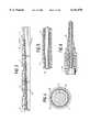
- FIG. 1is an elevational view of a guidewire embodying features of the invention.
- FIG. 2is an enlarged longitudinal cross-sectional view of a distal portion of the guidewire shown in FIG. 1.
- FIG. 3is an enlarged longitudinal cross-sectional view of the distal portion of a guidewire similar to that shown in FIG. 2 but having a plurality of braided layers.
- FIG. 4is a transverse cross-sectional view of the distal portion of the guidewire shown in FIG. 3 taken along the lines 4--4.
- FIG. 5is a longitudinal cross-sectional view of an intermediate portion of the guidewire shown in FIG. 1 taken along the lines 5--5.
- FIG. 6is a longitudinal cross-sectional view of the an 15 extension of the proximal end of the guidewire shown in FIG. 1 taken along the lines 6--6.
- FIG. 7is an elevational view, partially in section, of a catheter embodying features of the invention.
- FIG. 8is a transverse cross-sectional view of the catheter shown in FIG. 7 taken along the lines 8--8.
- FIG. 9is a schematic view of a patient's coronary arteries with guidewires shown in FIG. 1 disposed within the right coronary artery and the anterior interventricular branch of the left coronary arteries.
- FIG. 10is a schematic view of a patient's coronary arteries and the great cardiac vein with guidewires as shown in FIG. 1 disposed within the anterior interventricular branch of the left coronary artery and the great cardiac vein.
- FIG. 11is a longitudinal cross-sectional view of an alternative guidewire construction embodying features of the invention.
- FIG. 12is an elevational view, partially in section, of an alternative guidewire construction.
- FIG. 13is an elevational view, partially in section, of an alternative catheter construction embodying features of the invention.
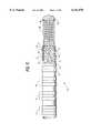
- FIG. 14is an enlarged elevational view partially in section of the distal portion of the catheter shown in FIG. 13.
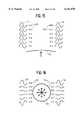
- FIG. 15is a schematic representation of responses of bipolar electrodes on separated intravascular devices from an essentially planar wave front.
- FIG. 16is a schematic representation of bipolar electrodes on separated intravascular devices from a circular wave front.
- FIG. 17is an electrocardiogram using a guidewire to detect electrical activity on the bipolar mode.
- FIGS. 1-5schematically illustrate an embodiment of the invention wherein the elongated device 10 is the form of a guidewire.
- the elongated device 10includes shaft 11 with a distal section 12 and a proximal section 13.
- the shaft 11is formed of a braided tubular member 14 formed of a plurality of electrical conductors 15.
- the distal section 12 of the shaft 11is provided with a plurality of bipolar electrode pairs 16, each pair of which includes electrodes 17 and 18.
- a core member 19is disposed within the inner lumen of the braided tubular member 14 and extends beyond the distal end thereof.
- a distal coil 20is disposed about and secured by suitable means, such as brazing, soldering or an appropriate adhesive, to the distal extremity of the core member 19 and is provided with a smooth rounded distal tip 21 formed by joining the distal tip of the coil 20 to the distal extremity of the core member 19.
- the distal extremity of the core member 19may be flattened into a rectangular cross-section.
- FIG. 2illustrates a single braided layer with sixteen strands.
- a plurality of braided layersmay be required, as depicted in FIG. 3.
- the outer braided layer 22terminates at a location proximal to that of the intermediate layer 23 and the intermediate layer terminates at a location proximal to the innermost layer 24 to facilitate securing and electrically connecting the electrodes 17 and 18 to the individual electrical conductors 15 as shown in FIG. 4.
- Some of the strands in the layersmay not be conductors and be formed of polymer materials such as nylon.
- proximal section 13 of the shaft 11 as shown in FIG. 1has two extensions 26 and 27 which have multi-pin connectors 28 and 29 on the proximal ends thereof with each of the electrical conductors 15 being electrically connected to a separate pin. Details of proximal extension 26 is depicted in FIG. 6. A sixteen pin connector is schematically shown in FIG. 6 but connectors having a higher or lower number of pins may be suitable.
- FIGS. 7 and 8schematically illustrate another presently preferred embodiment of the invention in the form of a catheter 30.
- the catheter shaft 31has an inner lumen 32 defined by an inner tubular element or lining 33 which is preferably formed of lubricous material such as Teflon®.
- a tubular member 34is disposed about tubular lining 33 and is formed of at least one braided layer 35.
- a plurality of the strands making up each of the braided layersare insulated 1 electrical conductors 38 which are electrically connected to individual electrodes 39 and 40 of electrode pairs 41 as in the previously described embodiment. While not shown in the drawing, a plurality of braided layers may be required with more than eight electrode pairs 41.
- the outer braided layershould terminate at a location proximal to that of the intermediate layer and the intermediate layer should terminate at a location proximal to the inner layer to facilitate securing and electrically connecting the electrodes 39 and 40 to the individual electrical conductors 38.
- Some of the strands in each of the layersmay be formed of other materials such as nylon.
- An outer jacket 42extends the length of the shaft 31 and the portion of the jacket extending beyond the distal end of the braided tubular member 34 is tapered to provide a nontraumatic flexible distal tip 43. As in the previously described example, the outer jacket 42 overlaps the edges of the electrodes 39 and 40 to avoid exposing a sharp metal edge when advancing the catheter through a patient's blood vessel.
- the catheter 30may be used by itself to detect electrical signals within the patient's coronary veins or arteries with the multiple electrode pairs 41 as in the previous embodiment. Additionally, the catheter may also be used to direct fluids containing cardioplegic materials such as iced saline, solutions of KCl, lidocaine, procaineamide hydrochloride and the like to areas of the patient's heart which are suspected to be the origin of or conduct the aberrant signals. If the arrhythmia stops upon the delivery of such cardioplegic agents, then the operator is assured that the artery or vein through which the agent is delivered leads toward or away from the region of the patient's heart which is to be ablated in order to terminate the arrhythmia.
- the signal reception by the electrode pairs 41are essentially the same as in the previously described guidewire embodiment.
- the catheter 30may also be used in conjunction with a guidewire 44 (shown in phantom) as illustrated in FIGS. 1-5.
- the catheter 30may be positioned at a first location within a coronary artery or cardiac vein of the patient with the guidewire 44, which has a plurality of bipolar electrode pairs 45 as in the previously discussed embodiment, disposed within the inner lumen of the catheter 30 and the distal section thereof extending out the port 46 in the distal end of the catheter into the patient's blood vessel. Adjustments in the relative locations of the guidewire 44 and catheter 30 can be easily made by moving the guidewire 44 through the inner lumen 32 of the catheter 30 or moving the catheter over the guidewire or both.
- a guiding catheterto guide the catheter or guidewire of the invention to the coronary artery ostium or the coronary sinus ostium.
- Such guiding cathetershave specially shaped distal tips to facilitating the seating thereof within the desired ostium, thus eliminating the trouble of directing a catheter or guidewire of the invention into the desire ostium.
- the bipolar electrodesare circular bands about 0.25 to about 1 mm in width and are preferably made from conducting material which is biocompatible with the body fluids such as gold.
- the electrodes of the electrode pairsare spaced from each other by about 0.5 to about 2 mm, preferably about 0.75 to about 1.25 mm, and the spacing between the bipolar electrode pairs is about 2 to about 10 mm, preferably about 7 to about 8 mm.
- the overall length of the intravascular devices of the inventionmay range from about 80 to about 300 cm, typically about 135 to about 175 cm for delivery through the femoral artery or vein and about 90 to about 120 cm for delivery through the brachiocephalic artery or internal jugular vein. If the guidewire is to be advanced through the inner lumen of the catheter it should be longer than the catheter by about 20 to about 40 cm.
- the distal section of the catheteris about 10 to about 50 cm in length and is configured to be readily advanceable through a patient's coronary arteries or cardiac veins.
- the outer diameter of the cathetershould be less than about 0.055 inch (1.4 mm) and preferably about 0.035 inch (0.89 mm).
- the inner lumen 32is about 0.012 to about 0.022 inch (0.3-0.56 mm) in diameter to facilitate the reception and advancement of a guidewire therethrough.
- the distal section of the guidewireis about 15 to about 40 cm in length and about 0.008 to about 0.022 inch (0.2-0.56 mm) in outer diameter to facilitate advancement through the coronary arteries and cardiac veins of a human being having natural diameters of less than 0.04 inch (1 mm), preferably less than 0.03 inch (0.75 mm).
- the distal coil on the guidewireis about 2 to about 10 cm in length and is formed of wire about 0.0003 to about 0.006 inch (0.008-0.153 mm) in diameter.
- the core member of the guidewiremay be tapered along its distal section in a conventional guidewire construction.
- the flattened distal portionhas a rectangular transverse cross section of about 0.002 by about 0.006 inch (0.051-0.15 mm)
- the materials of construction of the various guidewire and catheter partsmay be formed of conventional materials.
- the electrical conductorsmay be electrical grade copper wire about 0.005 inch (0.13 mm) in diameter which are provided with a thin insulated jacket or coating of polyimide or other suitable insulator.
- the outer jacketmay be a thermoplastic fluoropolymer such as THV which is available from the 3M Corporation.
- the distal tip coil on the guidewire form of the inventionis preferably formed of platinum to facilitate fluoroscopic observation thereof within the patient, but it may be formed in whole or in part with other material such as stainless steel, titanium, palladium, niobium, iridium, rhodium and alloys thereof.
- the core wire of the guidewiremay be formed of stainless steel or a superelastic NiTi type alloy, with the latter preferably having a stable austenite phase at body temperature and exhibiting a stress induced austenite-to-martensite phase transformation.
- Proximal and distal sections of the core membermay be formed of different materials so as to provide a stronger proximal section for greater pushability and a more flexible distal section to facilitate passage through tortuous coronary anatomy.
- FIG. 9One presently preferred method of using the elongated intravascular devices of the invention as shown in FIG. 9 wherein the distal portion 11 of the guidewires 10 such as shown in FIG. 1 are disposed within the right coronary artery 47 and the anterior interventricular branch of the left coronary artery 48. As indicated, the electrode pairs 16 on the distal portion 11 extend along a major portion of the arteries.
- the individual intravascular devicesmay be moved within the arteries as needed to optimize the signals received. While not shown in the drawings, the distal tip with the coil 20 may be shaped to facilitate entry into a side branch of the coronary artery.
- FIG. 10Another method is depicted in FIG. 10 wherein one of the elongated intravascular devices 10 of the invention are disposed within the great cardiac vein 49 and another is disposed within the anterior interventricular branch of the left coronary artery 48.
- a third intravascular devicemight also be deployed within the right coronary artery 47 as shown to provide a more comprehensive mapping of the patient's heart.
- the individual guidewires or other intravascular sensing devicesmay be moved within the artery or vein to better receive electrical activity.
- FIG. 11An alternative embodiment of the invention in the form of a guidewire 50 is shown in FIG. 11 which has a distal portion 51 with bipolar electrodes 52 and 53, an intermediate portion 54 and a proximal portion 55.
- a core member 56extends through the inner lumen 57 of the guidewire 50 from the proximal end to at least the distal portion 51.
- the distal bipolar electrode 52is electrically secured to the core member 56 by solder 58 and the proximal bipolar electrode 53 is secured by solder 59 to electrical conductor 60 which may be an insulated wire or ribbon.
- the proximal end of the electrical conductor 60is secured by solder 61 to conductive metal tube 62 (e.g. hypotubing) which is electrically isolated from the core member 56.
- conductive metal tube 62e.g. hypotubing
- the exterior surface of the core member 56 and the exterior of the conductive metal tube 62should be provided with an insulating jacket or coating to maintain the electrical isolation therebetween.
- the core member 56 and the conductive metal tube 62are preferably secured together at one or more locations by an insulating adhesive to facilitate the torqueability of the overall guidewire assembly.
- theyare secured at least at the distal end of the metal tube 62.
- a coil 63is disposed about core member 56 proximal to the bipolar electrode pair 52 and 53 and it is secured to the core member by a suitably adhesive 64 or solder or weld.
- the coil 63is preferably formed at least in part by a highly radiopaque biocompatible metal, e.g platinum, rhodium, palladium, tungsten, gold, silver or alloys thereof, to facilitate the fluoroscopic observation thereof when disposed within the vasculature of a patient.
- a palladium-tungsten alloyis preferred.
- the core member 56 and the coil 63provide shapeability to the distal portion 51 of the guidewire 50 to facilitate advancement thereof into side branches of a patient's vasculature.
- An insulating member 65is disposed between the coil 63 and the proximal bipolar electrode 53 and an insulating member 66 is disposed between electrodes 52 and 53.
- An inner tubular member 67may be disposed within the distal section to provide support to the electrodes 52 and 53 and inner tubular member 68 may be disposed within the coil 63 to likewise provide support thereto.
- a suitable materialis thin walled polyimide tubing which is commonly employed in intravascular catheters.
- a torquing knob 69is provided on the proximal end of core member 56.
- the guidewire 50may be of conventional intravascular guidewire construction.
- the overall lengthis about 150 to about 200 cm, the proximal OD of the core member 56 is typically about 0.013 inch and the distal OD about 0.006 inch which may be further reduced to 0.003 inch.
- the core member 56may be ground through one or more transitions to the smaller OD sections.
- the core member 56 and particularly the distal portion thereofmay be formed of a superelastic alloy such as NiTI which has a stable austenite phase at body temperature.
- the guidewire 70has a shaft 71 formed of woven or braided conductors 72 which are preferably insulated along their length and which extend to the proximal end of the shaft.
- a plurality of bipolar electrode pairs 73with each pair having a proximal electrode 74 and a distal electrode 75.
- Each of the electrodesare electrically connected to a separate electrical conductor 72 by suitable conductive solder 76. While it is preferable that the conductors are interwoven into the tube forming the shaft 71, the conductors may be twisted or wound.
- the core member 77extends through the interior of the guidewire shaft from the proximal end to the distal end thereof where it is secured to the distal tip or plug 79 of the guidewire 70.
- a helical coil 80is disposed about a distal portion of the core member 77 and is secured at its distal end to the distal tip or plug 79 and at its proximal end by adhesive 81.
- the coil 80is preferably formed at least in part by a radiopaque material such as those previously discussed.
- the core member 77may be configured as in the previous embodiments.
- the intravascular sensing devicebe introduced into a femoral artery or a femoral vein (or other convenient body access site) and be advanced through the patient's vasculature to the coronary veins or arteries.
- the intravascular deviceOnce the intravascular device is situated in the proper location in the coronary vasculature, electrical activity may be received in any way that is appropriate for the specific situation.
- the catheter or guidewiremay be moved to another location and another set of signals received. It should be apparent that since each electrode mounted on the distal section of the sensing device is individually brought out via the woven wires or filaments to the electrical connection at the proximal end, that each electrode may be used in conjunction with any other electrode in a bipolar mode.
- the sensing devicesmay be used in multiples, e.g., a sensing device in each of the major coronary veins and arteries, as shown in FIGS. 9 and 10, to provide an overall and complete electrical map of the heart. In this way, arrhythmic foci may be readily located and therapeutic action taken.
- FIGS. 13 and 14illustrate a catheter assembly 90 which embodies an additional aspect of the present invention directed to an intravascular catheter 91 for sensing electrical activity within a patient's coronary or cardiac blood vessels.
- the bipolar electrodes 92 and 93are electrically connected to individual electrical conductors 94 which are woven or wound to form the tubular shaft 95 of the catheter 91. All of the strands which are wound to form the shaft 95 need not be conductors 94 but may be strands of polymeric materials such as Dacron®, nylon, silk or other natural or synthetic polymeric material. When there are more than 16 electrodes and thus more than 16 electrical conductors, multiple woven layers may be employed.
- the electrical conductors 94are typically electrical grade copper wires of suitable outer diameter such as about 0.004 to about 0.01 inch (0.10-0.25 mm).
- the conductors 94may be formed of other conducting materials such as silver, gold and platinum.
- a suitable insulating material to coat the conductors 94is polyimide which minimizes cross talk and which can be applied in very thin layers.
- the conductors 94may be woven or merely wound, but preferably are woven.
- the inner lumen 95 of the catheter 91is configured to slidably receive a guidewire to facilitate the advancement of the catheter over the guidewire and preferably has at least in the distal portion thereof a diameter about 0.002 to about 0.005 inch (0.051-0.127 mm) greater than the guidewire which is to be disposed therein.
- the inner lumen 97would be about 0.018 to about 0.023 inch (0.46-0.58 mm).
- the OD of the cathetermay range from about 0.03 to about 0.1 inch (0.76-2.54 mm) but preferably is about 0.03 to about 0.05 inch (0.076-1.27 mm), particularly 0.035 to about 0.040 inch (0.89-1.02 mm).
- the proximal portion 96 of the catheter 91makes up about. 70 to about 95% of the total length of the catheter with the intermediate portion 97 and the distal portion 98 which has the sensing electrodes 92 and 93 being the remainder.
- the catheter 91has decreasing stiffness from the proximal portion 96 to the intermediate portion 97 and the distal portion 98 to facilitate the advancement of the catheter 91 within the patient's vasculature.
- the exterior surface of the catheter 91 and the surface defining inner lumen 95may be formed of lubricous materials or hydrophilic materials which become lubricous when contacting aqueous based fluids. Polysulfones and polyfluoroalkanes are examples of suitable lubricous polymers and polyvinylpyrrolidone, polyethylene oxide and acrylate-based polymers of examples of suitable hydrophilic polymers.
- the proximal end of the catheter 91may be provided with a multiple arm adapter 99 as shown in FIG. 13 with one arm 100 which is configured to receive a syringe for delivering fluid into the inner lumen 97 and a second arm 101 which is provided with an electrical connector 102 which is electrically connected to the electrical conductors 94.
- the central arm 106facilitates entry of a guidewire (not shown) into the inner lumen 97.
- the catheter 91may be advanced into position within the patient's vascular system, i.e. either the coronary arteries or the cardiac veins, over a guidewire which may or may not have electrodes in accordance with the invention to detect electrical activity therein.
- the guidewire over which the catheter is advanced into the patient's vasculaturemay be withdrawn when the catheter is in its desired position and a guidewire such as shown in FIG. 4 may be advanced through the inner lumen 95 of the catheter 91 and out the port 103 in the distal end of the catheter to a more distal position with the blood vessel.
- meanscan be advanced through the inner lumen 95 of a catheter of the invention to occlude an arterial passageway which feeds the arrhythmogenic site or conductive pathway so as to terminate the arrhythmia.
- FIG. 15represents an idealized output from a plurality of electrode pairs 110 and 111 on two separate intravascular devices (not shown) disposed in different, generally parallel coronary blood vessels, e.g. a coronary artery and the companion vein, to a nearly planar wave front 112 approaching on end to the intravascular devices.
- the bipolar response 113 and 114 to the wave front 111 from each electrode pair 110 and 111is shown adjacent thereto, and as indicated, all of the responses are essentially identical, except for the time-of-occurrence, because the wave front reaches all of the electrodes at the same angle. Changes in tissue properties, e.g. due to an infarct, adjacent the catheters may retard the passage of the wave front and as a result distort the shape of the output.
- FIG. 16represents an idealized response from a plurality of electrode pairs 120 and 121 on two separate intravascular devices (not shown) disposed in different generally parallel coronary blood vessels, as in FIG. 16, but the wave front 122 originates from a site between and in close proximity to the catheters.
- the idealized wave front 121is circular and the size and polarity of the responses 123 and 124 to the expanding wave front varies according to the angle of incidence between the wave front and the electrode pair.
- An arrhythmogenic sitewould create a less than ideal wave front which can be readily detected by the plurality of electrodes 120 and 121.
- the time of occurrence and directional information obtained from the response from the wave frontmay be used to determine the origin of the ectopic beat.
- a guidewirewas constructed using a woven tubular braid of sixteen insulated electrical conducting wires, eight woven counterclockwise and eight woven clockwise. Gold metal electrodes 0.01 inch in width were mounted onto the distal end of the shaft about 0.5 inch (12.7 mm) apart with each attached to one of the electrical conducting wires. The overall length of the guidewire was about 240 cm. An eight connector DIN plug was installed at the proximal end of the guidewire.
- the guidewire assemblywas 0.018 inch (0.46 mm) in diameter at the distal end, 0.026 inch (0.66 mm) in diameter at the midsection, and 0.032 inch (0.81 mm) at the more proximal end.
- FIG. 17is an electrocardiogram produced using the guidewire of the invention which depicts two pulses from that animal test in bipolar mode.
Landscapes
- Health & Medical Sciences (AREA)
- Life Sciences & Earth Sciences (AREA)
- Surgery (AREA)
- General Health & Medical Sciences (AREA)
- Veterinary Medicine (AREA)
- Public Health (AREA)
- Animal Behavior & Ethology (AREA)
- Engineering & Computer Science (AREA)
- Biomedical Technology (AREA)
- Heart & Thoracic Surgery (AREA)
- Medical Informatics (AREA)
- Molecular Biology (AREA)
- Vascular Medicine (AREA)
- Reproductive Health (AREA)
- Nuclear Medicine, Radiotherapy & Molecular Imaging (AREA)
- Pathology (AREA)
- Biophysics (AREA)
- Physics & Mathematics (AREA)
- Cardiology (AREA)
- Physiology (AREA)
- Measurement And Recording Of Electrical Phenomena And Electrical Characteristics Of The Living Body (AREA)
- Surgical Instruments (AREA)
- Measuring Pulse, Heart Rate, Blood Pressure Or Blood Flow (AREA)
- Media Introduction/Drainage Providing Device (AREA)
- Ultra Sonic Daignosis Equipment (AREA)
- External Artificial Organs (AREA)
- Electrotherapy Devices (AREA)
- Pharmaceuticals Containing Other Organic And Inorganic Compounds (AREA)
- Acyclic And Carbocyclic Compounds In Medicinal Compositions (AREA)
Abstract
Description
Claims (9)
Priority Applications (1)
| Application Number | Priority Date | Filing Date | Title |
|---|---|---|---|
| US08/763,202US6141576A (en) | 1993-01-29 | 1996-12-11 | Intravascular sensing device |
Applications Claiming Priority (6)
| Application Number | Priority Date | Filing Date | Title |
|---|---|---|---|
| US1081893A | 1993-01-29 | 1993-01-29 | |
| US4344993A | 1993-04-05 | 1993-04-05 | |
| US5729493A | 1993-05-05 | 1993-05-05 | |
| US08/188,619US5509411A (en) | 1993-01-29 | 1994-01-27 | Intravascular sensing device |
| US48212095A | 1995-06-07 | 1995-06-07 | |
| US08/763,202US6141576A (en) | 1993-01-29 | 1996-12-11 | Intravascular sensing device |
Related Parent Applications (1)
| Application Number | Title | Priority Date | Filing Date |
|---|---|---|---|
| US48212095AContinuation | 1993-01-29 | 1995-06-07 |
Publications (1)
| Publication Number | Publication Date |
|---|---|
| US6141576Atrue US6141576A (en) | 2000-10-31 |
Family
ID=27359312
Family Applications (5)
| Application Number | Title | Priority Date | Filing Date |
|---|---|---|---|
| US08/188,298Expired - LifetimeUS5706809A (en) | 1993-01-29 | 1994-01-27 | Method and system for using multiple intravascular sensing devices to detect electrical activity |
| US08/188,619Expired - LifetimeUS5509411A (en) | 1992-01-29 | 1994-01-27 | Intravascular sensing device |
| US08/636,509Expired - LifetimeUS5682885A (en) | 1993-01-29 | 1996-04-19 | Intravascular sensing device |
| US08/763,202Expired - LifetimeUS6141576A (en) | 1993-01-29 | 1996-12-11 | Intravascular sensing device |
| US08/963,771Expired - LifetimeUS5967978A (en) | 1993-01-29 | 1997-11-04 | Intravascular sensing device |
Family Applications Before (3)
| Application Number | Title | Priority Date | Filing Date |
|---|---|---|---|
| US08/188,298Expired - LifetimeUS5706809A (en) | 1993-01-29 | 1994-01-27 | Method and system for using multiple intravascular sensing devices to detect electrical activity |
| US08/188,619Expired - LifetimeUS5509411A (en) | 1992-01-29 | 1994-01-27 | Intravascular sensing device |
| US08/636,509Expired - LifetimeUS5682885A (en) | 1993-01-29 | 1996-04-19 | Intravascular sensing device |
Family Applications After (1)
| Application Number | Title | Priority Date | Filing Date |
|---|---|---|---|
| US08/963,771Expired - LifetimeUS5967978A (en) | 1993-01-29 | 1997-11-04 | Intravascular sensing device |
Country Status (9)
| Country | Link |
|---|---|
| US (5) | US5706809A (en) |
| EP (1) | EP0681450B1 (en) |
| JP (3) | JPH08506034A (en) |
| AT (1) | ATE214569T1 (en) |
| AU (3) | AU692762B2 (en) |
| CA (1) | CA2154773C (en) |
| DE (1) | DE69430192T2 (en) |
| ES (1) | ES2173913T3 (en) |
| WO (3) | WO1994016619A1 (en) |
Cited By (95)
| Publication number | Priority date | Publication date | Assignee | Title |
|---|---|---|---|---|
| US6532378B2 (en)* | 2000-01-14 | 2003-03-11 | Ep Medsystems, Inc. | Pulmonary artery catheter for left and right atrial recording |
| US6539265B2 (en)* | 1998-05-07 | 2003-03-25 | Medtronic, Inc. | Apparatus for rf intraluminal reduction and occlusion |
| US20030065374A1 (en)* | 2001-10-01 | 2003-04-03 | Medtronic, Inc. | Active fixation lead with helix extension indicator |
| EP1287782A3 (en)* | 2001-08-30 | 2003-08-13 | Biosense Webster, Inc. | Catheter having mapping assembly |
| US20030216800A1 (en)* | 2002-04-11 | 2003-11-20 | Medtronic, Inc. | Implantable medical device conductor insulation and process for forming |
| US6671560B2 (en) | 1998-06-12 | 2003-12-30 | Cardiac Pacemakers, Inc. | Modified guidewire for left ventricular access lead |
| US6697667B1 (en) | 2001-05-31 | 2004-02-24 | Advanced Cardiovascular Systems, Inc. | Apparatus and method for locating coronary sinus |
| US6716178B1 (en) | 2001-05-31 | 2004-04-06 | Advanced Cardiovascular Systems, Inc. | Apparatus and method for performing thermal and laser doppler velocimetry measurements |
| US20040158139A1 (en)* | 2000-01-27 | 2004-08-12 | Fuimaono Kristine B. | Method for mapping electrical activity |
| US20040181137A1 (en)* | 2003-03-12 | 2004-09-16 | Rodriguez Cynthia D. | Catheter with contractable mapping assembly |
| US6795721B2 (en) | 2000-01-27 | 2004-09-21 | Biosense Webster, Inc. | Bidirectional catheter having mapping assembly |
| US20050004643A1 (en)* | 2002-04-11 | 2005-01-06 | Ebert Michael J. | Implantable medical device conductor insulation and process for forming |
| US20050085885A1 (en)* | 1998-08-12 | 2005-04-21 | Cardiac Pacemakers, Inc. | Expandable seal for use with medical device and system |
| US20050130107A1 (en)* | 2003-12-15 | 2005-06-16 | Ellingson Elizabeth A. | Heart model |
| US20050137646A1 (en)* | 2003-12-22 | 2005-06-23 | Scimed Life Systems, Inc. | Method of intravascularly delivering stimulation leads into brain |
| US20050187589A1 (en)* | 2004-02-20 | 2005-08-25 | Scimed Life Systems, Inc. | Method of stimulating/sensing brain with combination of intravascularly and non-vascularly delivered leads |
| US20050251238A1 (en)* | 2004-05-06 | 2005-11-10 | Scimed Life Systems, Inc. | Intravascular self-anchoring integrated tubular electrode body |
| US7082336B2 (en) | 2003-06-04 | 2006-07-25 | Synecor, Llc | Implantable intravascular device for defibrillation and/or pacing |
| US7174220B1 (en)* | 2004-03-16 | 2007-02-06 | Pacesetter, Inc. | Construction of a medical electrical lead |
| US7177702B2 (en) | 2004-03-12 | 2007-02-13 | Scimed Life Systems, Inc. | Collapsible/expandable electrode leads |
| US20070038055A1 (en)* | 2000-01-27 | 2007-02-15 | Biosense Webster, Inc. | Catheter having mapping assembly |
| US20070106293A1 (en)* | 2002-10-25 | 2007-05-10 | Hakan Oral | Ablation catheters |
| US20070233215A1 (en)* | 2003-04-04 | 2007-10-04 | Sommer John L | Mapping guidelet |
| US7286879B2 (en) | 2004-07-16 | 2007-10-23 | Boston Scientific Scimed, Inc. | Method of stimulating fastigium nucleus to treat neurological disorders |
| US20070265673A1 (en)* | 2006-04-03 | 2007-11-15 | Terrance Ransbury | Flexible interconnect assembly for implantable medical devices |
| US7329223B1 (en) | 2001-05-31 | 2008-02-12 | Abbott Cardiovascular Systems Inc. | Catheter with optical fiber sensor |
| US20080076999A1 (en)* | 2006-09-05 | 2008-03-27 | Boston Scientific Scimed, Inc. | Multi-bend steerable mapping catheter |
| US20080147168A1 (en)* | 2006-12-04 | 2008-06-19 | Terrance Ransbury | Intravascular implantable device having detachable tether arrangement |
| US20080167702A1 (en)* | 2006-12-04 | 2008-07-10 | Terrance Ransbury | Intravascular implantable device having superior anchoring arrangement |
| US7429261B2 (en) | 2004-11-24 | 2008-09-30 | Ablation Frontiers, Inc. | Atrial ablation catheter and method of use |
| US7468062B2 (en) | 2004-11-24 | 2008-12-23 | Ablation Frontiers, Inc. | Atrial ablation catheter adapted for treatment of septal wall arrhythmogenic foci and method of use |
| US7529589B2 (en) | 2003-06-04 | 2009-05-05 | Synecor Llc | Intravascular electrophysiological system and methods |
| US7532920B1 (en) | 2001-05-31 | 2009-05-12 | Advanced Cardiovascular Systems, Inc. | Guidewire with optical fiber |
| US7537595B2 (en) | 2001-12-12 | 2009-05-26 | Tissuelink Medical, Inc. | Fluid-assisted medical devices, systems and methods |
| US20090177193A1 (en)* | 2006-10-10 | 2009-07-09 | Huisun Wang | Irrigated ablation electrode having smooth edges to minimize tissue char |
| US7590454B2 (en) | 2004-03-12 | 2009-09-15 | Boston Scientific Neuromodulation Corporation | Modular stimulation lead network |
| US7604635B2 (en) | 2000-03-06 | 2009-10-20 | Salient Surgical Technologies, Inc. | Fluid-assisted medical devices, systems and methods |
| US7617007B2 (en) | 2003-06-04 | 2009-11-10 | Synecor Llc | Method and apparatus for retaining medical implants within body vessels |
| US7645277B2 (en) | 2000-09-22 | 2010-01-12 | Salient Surgical Technologies, Inc. | Fluid-assisted medical device |
| US7657324B2 (en) | 1998-08-12 | 2010-02-02 | Cardiac Pacemakers, Inc. | Seal for use with cardiac lead |
| US7722565B2 (en) | 2004-11-05 | 2010-05-25 | Traxtal, Inc. | Access system |
| US7727232B1 (en) | 2004-02-04 | 2010-06-01 | Salient Surgical Technologies, Inc. | Fluid-assisted medical devices and methods |
| US7747335B2 (en) | 2003-12-12 | 2010-06-29 | Synecor Llc | Implantable medical device having pre-implant exoskeleton |
| US7751868B2 (en) | 2004-11-12 | 2010-07-06 | Philips Electronics Ltd | Integrated skin-mounted multifunction device for use in image-guided surgery |
| US20100217184A1 (en)* | 2009-02-20 | 2010-08-26 | Boston Scientific Scimed, Inc. | Steerable catheter having intermediate stiffness transition zone |
| US7805269B2 (en) | 2004-11-12 | 2010-09-28 | Philips Electronics Ltd | Device and method for ensuring the accuracy of a tracking device in a volume |
| US20100249654A1 (en)* | 2007-09-18 | 2010-09-30 | Cook Incorporated | Wire guide |
| US7811282B2 (en) | 2000-03-06 | 2010-10-12 | Salient Surgical Technologies, Inc. | Fluid-assisted electrosurgical devices, electrosurgical unit with pump and methods of use thereof |
| US7815634B2 (en) | 2000-03-06 | 2010-10-19 | Salient Surgical Technologies, Inc. | Fluid delivery system and controller for electrosurgical devices |
| US7840254B2 (en) | 2005-01-18 | 2010-11-23 | Philips Electronics Ltd | Electromagnetically tracked K-wire device |
| US7850685B2 (en) | 2005-06-20 | 2010-12-14 | Medtronic Ablation Frontiers Llc | Ablation catheter |
| US20100318166A1 (en)* | 2009-06-12 | 2010-12-16 | Terrance Ransbury | Methods and systems for anti-thrombotic intravascular implantable devices |
| US20110004288A1 (en)* | 2009-06-12 | 2011-01-06 | Terrance Ransbury | Intravascular implantable device having integrated anchor mechanism |
| US7937160B2 (en) | 2004-12-10 | 2011-05-03 | Boston Scientific Neuromodulation Corporation | Methods for delivering cortical electrode leads into patient's head |
| US7951148B2 (en) | 2001-03-08 | 2011-05-31 | Salient Surgical Technologies, Inc. | Electrosurgical device having a tissue reduction sensor |
| US7998140B2 (en) | 2002-02-12 | 2011-08-16 | Salient Surgical Technologies, Inc. | Fluid-assisted medical devices, systems and methods |
| US8019441B2 (en) | 2004-03-12 | 2011-09-13 | Boston Scientific Neuromodulation Corporation | Collapsible/expandable tubular electrode leads |
| US8060207B2 (en) | 2003-12-22 | 2011-11-15 | Boston Scientific Scimed, Inc. | Method of intravascularly delivering stimulation leads into direct contact with tissue |
| US8083736B2 (en) | 2000-03-06 | 2011-12-27 | Salient Surgical Technologies, Inc. | Fluid-assisted medical devices, systems and methods |
| US8239045B2 (en) | 2003-06-04 | 2012-08-07 | Synecor Llc | Device and method for retaining a medical device within a vessel |
| US8475455B2 (en) | 2002-10-29 | 2013-07-02 | Medtronic Advanced Energy Llc | Fluid-assisted electrosurgical scissors and methods |
| US8486063B2 (en) | 2004-10-14 | 2013-07-16 | Medtronic Ablation Frontiers Llc | Ablation catheter |
| US8611983B2 (en) | 2005-01-18 | 2013-12-17 | Philips Electronics Ltd | Method and apparatus for guiding an instrument to a target in the lung |
| US8617152B2 (en) | 2004-11-15 | 2013-12-31 | Medtronic Ablation Frontiers Llc | Ablation system with feedback |
| US8632533B2 (en) | 2009-02-23 | 2014-01-21 | Medtronic Advanced Energy Llc | Fluid-assisted electrosurgical device |
| US8632461B2 (en) | 2005-06-21 | 2014-01-21 | Koninklijke Philips N.V. | System, method and apparatus for navigated therapy and diagnosis |
| US8641704B2 (en) | 2007-05-11 | 2014-02-04 | Medtronic Ablation Frontiers Llc | Ablation therapy system and method for treating continuous atrial fibrillation |
| US8657814B2 (en) | 2005-08-22 | 2014-02-25 | Medtronic Ablation Frontiers Llc | User interface for tissue ablation system |
| US8834461B2 (en) | 2005-07-11 | 2014-09-16 | Medtronic Ablation Frontiers Llc | Low power tissue ablation system |
| US8870864B2 (en) | 2011-10-28 | 2014-10-28 | Medtronic Advanced Energy Llc | Single instrument electrosurgery apparatus and its method of use |
| US8882756B2 (en) | 2007-12-28 | 2014-11-11 | Medtronic Advanced Energy Llc | Fluid-assisted electrosurgical devices, methods and systems |
| US8906012B2 (en) | 2010-06-30 | 2014-12-09 | Medtronic Advanced Energy Llc | Electrosurgical devices with wire electrode |
| US8920417B2 (en) | 2010-06-30 | 2014-12-30 | Medtronic Advanced Energy Llc | Electrosurgical devices and methods of use thereof |
| US9023040B2 (en) | 2010-10-26 | 2015-05-05 | Medtronic Advanced Energy Llc | Electrosurgical cutting devices |
| US9138289B2 (en) | 2010-06-28 | 2015-09-22 | Medtronic Advanced Energy Llc | Electrode sheath for electrosurgical device |
| US9254168B2 (en) | 2009-02-02 | 2016-02-09 | Medtronic Advanced Energy Llc | Electro-thermotherapy of tissue using penetrating microelectrode array |
| US9333027B2 (en)* | 2010-05-28 | 2016-05-10 | Medtronic Advanced Energy Llc | Method of producing an electrosurgical device |
| US9345541B2 (en) | 2009-09-08 | 2016-05-24 | Medtronic Advanced Energy Llc | Cartridge assembly for electrosurgical devices, electrosurgical unit and methods of use thereof |
| US9398892B2 (en) | 2005-06-21 | 2016-07-26 | Koninklijke Philips N.V. | Device and method for a trackable ultrasound |
| US9427281B2 (en) | 2011-03-11 | 2016-08-30 | Medtronic Advanced Energy Llc | Bronchoscope-compatible catheter provided with electrosurgical device |
| US9446219B2 (en) | 2011-10-04 | 2016-09-20 | Lake Region Manufacturing, Inc. | Multiconductor or multipolar guidewire |
| US9592090B2 (en) | 2010-03-11 | 2017-03-14 | Medtronic Advanced Energy Llc | Bipolar electrosurgical cutter with position insensitive return electrode contact |
| US9661991B2 (en) | 2005-08-24 | 2017-05-30 | Koninklijke Philips N.V. | System, method and devices for navigated flexible endoscopy |
| US9750565B2 (en) | 2011-09-30 | 2017-09-05 | Medtronic Advanced Energy Llc | Electrosurgical balloons |
| US9956029B2 (en) | 2014-10-31 | 2018-05-01 | Medtronic Advanced Energy Llc | Telescoping device with saline irrigation line |
| US9974599B2 (en) | 2014-08-15 | 2018-05-22 | Medtronic Ps Medical, Inc. | Multipurpose electrosurgical device |
| US10321890B2 (en) | 2005-05-06 | 2019-06-18 | Arrow International, Inc. | Apparatus and method for endovascular device guiding and positioning using physiological parameters |
| US10368837B2 (en) | 2005-05-06 | 2019-08-06 | Arrow International, Inc. | Apparatus and method for vascular access |
| US10582879B2 (en) | 2004-02-17 | 2020-03-10 | Philips Electronics Ltd | Method and apparatus for registration, verification and referencing of internal organs |
| US10631914B2 (en) | 2013-09-30 | 2020-04-28 | Covidien Lp | Bipolar electrosurgical instrument with movable electrode and related systems and methods |
| US10716612B2 (en) | 2015-12-18 | 2020-07-21 | Medtronic Advanced Energy Llc | Electrosurgical device with multiple monopolar electrode assembly |
| US11051875B2 (en) | 2015-08-24 | 2021-07-06 | Medtronic Advanced Energy Llc | Multipurpose electrosurgical device |
| US11389227B2 (en) | 2015-08-20 | 2022-07-19 | Medtronic Advanced Energy Llc | Electrosurgical device with multivariate control |
| US12023082B2 (en) | 2017-10-06 | 2024-07-02 | Medtronic Advanced Energy Llc | Hemostatic thermal sealer |
| US12150716B2 (en) | 2005-05-06 | 2024-11-26 | Teleflex Life Sciences Llc | Endovascular navigation system and method |
Families Citing this family (324)
| Publication number | Priority date | Publication date | Assignee | Title |
|---|---|---|---|---|
| US5699796A (en)* | 1993-01-29 | 1997-12-23 | Cardima, Inc. | High resolution intravascular signal detection |
| US5645082A (en)* | 1993-01-29 | 1997-07-08 | Cardima, Inc. | Intravascular method and system for treating arrhythmia |
| US5706809A (en)* | 1993-01-29 | 1998-01-13 | Cardima, Inc. | Method and system for using multiple intravascular sensing devices to detect electrical activity |
| DK0681451T3 (en)* | 1993-01-29 | 2001-12-17 | Medtronic Inc | Multiple intravascular devices for sensing electrical activity |
| WO1995009561A1 (en)* | 1993-10-01 | 1995-04-13 | Target Therapeutics, Inc. | Sheathed multipolar catheter and multipolar guidewire for sensing cardiac electrical activity |
| US5517989A (en)* | 1994-04-01 | 1996-05-21 | Cardiometrics, Inc. | Guidewire assembly |
| US6245068B1 (en) | 1994-08-08 | 2001-06-12 | Scimed Life Systems, Inc. | Resilient radiopaque electrophysiology electrodes and probes including the same |
| WO1996004954A1 (en)* | 1994-08-17 | 1996-02-22 | Boston Scientific Corporation | Implant, and method and device for inserting the implant |
| IL116561A0 (en)* | 1994-12-30 | 1996-03-31 | Target Therapeutics Inc | Severable joint for detachable devices placed within the body |
| US6101409A (en)* | 1995-02-17 | 2000-08-08 | Ep Technologies, Inc. | Systems and methods for analyzing biopotential morphologies in body tissue |
| US5601088A (en)* | 1995-02-17 | 1997-02-11 | Ep Technologies, Inc. | Systems and methods for filtering artifacts from composite signals |
| US5711305A (en) | 1995-02-17 | 1998-01-27 | Ep Technologies, Inc. | Systems and methods for acquiring endocardially or epicardially paced electrocardiograms |
| US5595183A (en)* | 1995-02-17 | 1997-01-21 | Ep Technologies, Inc. | Systems and methods for examining heart tissue employing multiple electrode structures and roving electrodes |
| CA2213133C (en)* | 1995-02-17 | 2003-06-17 | Ep Technologies, Inc. | Systems and methods for making time-sequential measurements of biological events |
| US5609157A (en)* | 1995-02-17 | 1997-03-11 | Ep Technologies, Inc. | Systems and methods for analyzing biopotential morphologies in body tissue using iterative techniques |
| US5722416A (en)* | 1995-02-17 | 1998-03-03 | Ep Technologies, Inc. | Systems and methods for analyzing biopotential morphologies in heart tissue to locate potential ablation sites |
| US5630425A (en)* | 1995-02-17 | 1997-05-20 | Ep Technologies, Inc. | Systems and methods for adaptive filtering artifacts from composite signals |
| US5605157A (en)* | 1995-02-17 | 1997-02-25 | Ep Technologies, Inc. | Systems and methods for filtering signals derived from biological events |
| US6059779A (en)* | 1995-04-28 | 2000-05-09 | Target Therapeutics, Inc. | Delivery catheter for electrolytically detachable implant |
| US6002956A (en)* | 1995-05-23 | 1999-12-14 | Cardima, Inc. | Method of treating using an over-the-wire EP catheter |
| US5782760A (en)* | 1995-05-23 | 1998-07-21 | Cardima, Inc. | Over-the-wire EP catheter |
| US5895355A (en) | 1995-05-23 | 1999-04-20 | Cardima, Inc. | Over-the-wire EP catheter |
| WO1996040342A1 (en)* | 1995-06-07 | 1996-12-19 | Cardima, Inc. | Guiding catheter for coronary sinus |
| JP3529537B2 (en)* | 1996-03-25 | 2004-05-24 | テルモ株式会社 | Electrode catheter |
| US6302880B1 (en) | 1996-04-08 | 2001-10-16 | Cardima, Inc. | Linear ablation assembly |
| US6063077A (en)* | 1996-04-08 | 2000-05-16 | Cardima, Inc. | Linear ablation device and assembly |
| US5863291A (en)* | 1996-04-08 | 1999-01-26 | Cardima, Inc. | Linear ablation assembly |
| US5755718A (en)* | 1996-06-04 | 1998-05-26 | Sklar; Joseph H. | Apparatus and method for reconstructing ligaments |
| US5824026A (en)* | 1996-06-12 | 1998-10-20 | The Spectranetics Corporation | Catheter for delivery of electric energy and a process for manufacturing same |
| US5964793A (en)* | 1996-06-20 | 1999-10-12 | Rutten; Jean | Lead introducer with defibrillation electrode and method of atrial defibrillation |
| US5766152A (en) | 1996-08-15 | 1998-06-16 | Cardima, Inc. | Intraluminal delivery of tissue lysing medium |
| US5964797A (en)* | 1996-08-30 | 1999-10-12 | Target Therapeutics, Inc. | Electrolytically deployable braided vaso-occlusion device |
| EP0927060B1 (en)* | 1996-09-23 | 2009-04-01 | Best Vascular, Inc. | Intraluminal radiation treatment system |
| US5690667A (en)* | 1996-09-26 | 1997-11-25 | Target Therapeutics | Vasoocclusion coil having a polymer tip |
| US6002955A (en)* | 1996-11-08 | 1999-12-14 | Medtronic, Inc. | Stabilized electrophysiology catheter and method for use |
| USH1905H (en)* | 1997-03-21 | 2000-10-03 | Medtronic, Inc. | Mechanism for adjusting the exposed surface area and position of an electrode along a lead body |
| US5971983A (en)* | 1997-05-09 | 1999-10-26 | The Regents Of The University Of California | Tissue ablation device and method of use |
| US6024740A (en) | 1997-07-08 | 2000-02-15 | The Regents Of The University Of California | Circumferential ablation device assembly |
| US6012457A (en) | 1997-07-08 | 2000-01-11 | The Regents Of The University Of California | Device and method for forming a circumferential conduction block in a pulmonary vein |
| EP0893093A1 (en)* | 1997-07-25 | 1999-01-27 | Sulzer Osypka GmbH | Catheter for the endocardial detection of heart potentials |
| AU8913998A (en) | 1997-08-28 | 1999-03-22 | Boston Scientific Corporation | System for implanting a cross-linked polysaccharide fiber and methods of formingand inserting the fiber |
| US6589199B1 (en) | 1997-08-28 | 2003-07-08 | Boston Scientific Corporation | System for implanting a cross-linked polysaccharide fiber and methods of forming and inserting the fiber |
| US5938624A (en)* | 1997-09-10 | 1999-08-17 | Radi Medical Systems Ab | Male connector with a continous surface for a guide wire and method therefor |
| US6241691B1 (en) | 1997-12-05 | 2001-06-05 | Micrus Corporation | Coated superelastic stent |
| US6136015A (en)* | 1998-08-25 | 2000-10-24 | Micrus Corporation | Vasoocclusive coil |
| US6168570B1 (en) | 1997-12-05 | 2001-01-02 | Micrus Corporation | Micro-strand cable with enhanced radiopacity |
| US6159165A (en)* | 1997-12-05 | 2000-12-12 | Micrus Corporation | Three dimensional spherical micro-coils manufactured from radiopaque nickel-titanium microstrand |
| US6251092B1 (en) | 1997-12-30 | 2001-06-26 | Medtronic, Inc. | Deflectable guiding catheter |
| US6344037B1 (en)* | 1998-02-03 | 2002-02-05 | Scimed Life Systems, Inc. | Integrated coaxial transmission line and flexible drive cable |
| US6714823B1 (en)* | 1998-04-29 | 2004-03-30 | Emory University | Cardiac pacing lead and delivery system |
| US6231572B1 (en)* | 1998-05-29 | 2001-05-15 | Applied Medical Resources Corporation | Electrosurgical catheter apparatus and method |
| US6251107B1 (en)* | 1998-06-25 | 2001-06-26 | Cardima, Inc. | Ep catheter |
| US6241665B1 (en) | 1998-10-21 | 2001-06-05 | Plc Medical System, Inc. | Percutaneous mapping system |
| US6332881B1 (en) | 1999-09-01 | 2001-12-25 | Cardima, Inc. | Surgical ablation tool |
| US6980958B1 (en)* | 2000-01-11 | 2005-12-27 | Zycare, Inc. | Apparatus and methods for monitoring and modifying anticoagulation therapy of remotely located patients |
| US20040246551A1 (en)* | 2000-02-18 | 2004-12-09 | Reijnen Herman Hubertus Jacobus | Window |
| WO2001072368A2 (en) | 2000-03-31 | 2001-10-04 | Medtronic, Inc. | Intralumenal visualization system with deflectable mechanism |
| US6733500B2 (en) | 2000-03-31 | 2004-05-11 | Medtronic, Inc. | Method and system for delivering a medical electrical lead within a venous system |
| US7497844B2 (en)* | 2000-03-31 | 2009-03-03 | Medtronic, Inc. | System and method for positioning implantable medical devices within coronary veins |
| US6836687B2 (en) | 2000-03-31 | 2004-12-28 | Medtronic, Inc. | Method and system for delivery of a medical electrical lead within a venous system |
| WO2001082814A2 (en) | 2000-05-03 | 2001-11-08 | C.R. Bard, Inc. | Apparatus and methods for mapping and ablation in electrophysiology procedures |
| US6746446B1 (en) | 2000-08-04 | 2004-06-08 | Cardima, Inc. | Electrophysiological device for the isthmus |
| US20030149368A1 (en)* | 2000-10-24 | 2003-08-07 | Hennemann Willard W. | Method and apparatus for locating and detecting vascular plaque via impedence and conductivity measurements, and for cryogenically passivating vascular plaque and inhibiting vascular plaque progression and rupture |
| US20020072737A1 (en)* | 2000-12-08 | 2002-06-13 | Medtronic, Inc. | System and method for placing a medical electrical lead |
| US7255695B2 (en) | 2001-04-27 | 2007-08-14 | C.R. Bard, Inc. | Systems and methods for three-dimensional mapping of electrical activity |
| US6972016B2 (en)* | 2001-05-01 | 2005-12-06 | Cardima, Inc. | Helically shaped electrophysiology catheter |
| US7727229B2 (en) | 2001-05-01 | 2010-06-01 | C.R. Bard, Inc. | Method and apparatus for altering conduction properties in the heart and in adjacent vessels |
| DE10153842A1 (en) | 2001-10-24 | 2003-05-08 | Biotronik Mess & Therapieg | electrode assembly |
| US7065394B2 (en)* | 2001-12-12 | 2006-06-20 | Medtronic, Inc | Guide catheter |
| US20040073158A1 (en)* | 2001-12-12 | 2004-04-15 | Medtronic, Inc. | Guide catheter |
| US20030144718A1 (en)* | 2002-01-29 | 2003-07-31 | Zeijlemaker Volkert A. | Method and apparatus for shielding coating for MRI resistant electrode systems |
| US7653438B2 (en) | 2002-04-08 | 2010-01-26 | Ardian, Inc. | Methods and apparatus for renal neuromodulation |
| US7640053B2 (en)* | 2002-06-26 | 2009-12-29 | Endosense S.A. | Catheterization method and system for controlling tip displacement |
| US20040024425A1 (en)* | 2002-07-31 | 2004-02-05 | Worley Seth J. | Method and apparatus for using a cardiac stimulating, sensing and guidewire combination |
| US7313445B2 (en)* | 2002-09-26 | 2007-12-25 | Medtronic, Inc. | Medical lead with flexible distal guidewire extension |
| US20050033137A1 (en)* | 2002-10-25 | 2005-02-10 | The Regents Of The University Of Michigan | Ablation catheters and methods for their use |
| CA2508800A1 (en) | 2002-12-11 | 2004-06-24 | Proteus Biomedical, Inc. | Method and system for monitoring and treating hemodynamic parameters |
| JP4465349B2 (en)* | 2003-01-24 | 2010-05-19 | プロテウス バイオメディカル インコーポレイテッド | Method and system for measuring cardiac parameters |
| US7200439B2 (en) | 2003-01-24 | 2007-04-03 | Proteus Biomedical, Inc. | Method and apparatus for enhancing cardiac pacing |
| WO2004066814A2 (en)* | 2003-01-24 | 2004-08-12 | Proteus Biomedical Inc. | Method and system for remote hemodynamic monitoring |
| DE202004021953U1 (en) | 2003-09-12 | 2013-06-19 | Vessix Vascular, Inc. | Selectable eccentric remodeling and / or ablation of atherosclerotic material |
| US7142919B2 (en)* | 2003-10-24 | 2006-11-28 | Medtronic, Inc. | Reconfigurable, fault tolerant multiple-electrode cardiac lead systems |
| AU2005212341B2 (en)* | 2004-02-10 | 2011-11-24 | Synecor, Llc. | Intravascular delivery system for therapeutic agents |
| WO2006029090A2 (en)* | 2004-09-02 | 2006-03-16 | Proteus Biomedical, Inc. | Methods and apparatus for tissue activation and monitoring |
| US9713730B2 (en) | 2004-09-10 | 2017-07-25 | Boston Scientific Scimed, Inc. | Apparatus and method for treatment of in-stent restenosis |
| US8396548B2 (en) | 2008-11-14 | 2013-03-12 | Vessix Vascular, Inc. | Selective drug delivery in a lumen |
| US7949407B2 (en) | 2004-11-05 | 2011-05-24 | Asthmatx, Inc. | Energy delivery devices and methods |
| WO2006052940A2 (en) | 2004-11-05 | 2006-05-18 | Asthmatx, Inc. | Medical device with procedure improvement features |
| US20070093802A1 (en)* | 2005-10-21 | 2007-04-26 | Danek Christopher J | Energy delivery devices and methods |
| US7412273B2 (en) | 2004-11-15 | 2008-08-12 | Biosense Webster, Inc. | Soft linear mapping catheter with stabilizing tip |
| US20060135953A1 (en)* | 2004-12-22 | 2006-06-22 | Wlodzimierz Kania | Tissue ablation system including guidewire with sensing element |
| US8075498B2 (en) | 2005-03-04 | 2011-12-13 | Endosense Sa | Medical apparatus system having optical fiber load sensing capability |
| US8182433B2 (en) | 2005-03-04 | 2012-05-22 | Endosense Sa | Medical apparatus system having optical fiber load sensing capability |
| EP1871470A4 (en)* | 2005-03-31 | 2011-06-01 | Proteus Biomedical Inc | Automated optimization of multi-electrode pacing for cardiac resynchronization |
| US20090299447A1 (en)* | 2005-07-01 | 2009-12-03 | Marc Jensen | Deployable epicardial electrode and sensor array |
| EP2363073B1 (en) | 2005-08-01 | 2015-10-07 | St. Jude Medical Luxembourg Holding S.à.r.l. | Medical apparatus system having optical fiber load sensing capability |
| WO2007021804A2 (en)* | 2005-08-12 | 2007-02-22 | Proteus Biomedical, Inc. | Evaluation of depolarization wave conduction velocity |
| US8784336B2 (en) | 2005-08-24 | 2014-07-22 | C. R. Bard, Inc. | Stylet apparatuses and methods of manufacture |
| US8696656B2 (en) | 2005-11-18 | 2014-04-15 | Medtronic Cryocath Lp | System and method for monitoring bioimpedance and respiration |
| US7842031B2 (en)* | 2005-11-18 | 2010-11-30 | Medtronic Cryocath Lp | Bioimpedance measurement system and method |
| JP2009521276A (en)* | 2005-12-22 | 2009-06-04 | プロテウス バイオメディカル インコーポレイテッド | Implantable integrated circuit |
| US11234761B2 (en)* | 2006-01-27 | 2022-02-01 | Baylis Medical Company Inc. | Electrosurgical device for creating a channel through a region of tissue and methods of use thereof |
| US20220151681A1 (en)* | 2006-01-27 | 2022-05-19 | Baylis Medical Company Inc. | Electrosurgical Device for Creating a Channel through a Region of Tissue and Methods of Use thereof |
| US8019435B2 (en) | 2006-05-02 | 2011-09-13 | Boston Scientific Scimed, Inc. | Control of arterial smooth muscle tone |
| US8048063B2 (en) | 2006-06-09 | 2011-11-01 | Endosense Sa | Catheter having tri-axial force sensor |
| US8567265B2 (en) | 2006-06-09 | 2013-10-29 | Endosense, SA | Triaxial fiber optic force sensing catheter |
| US12161390B2 (en) | 2006-09-29 | 2024-12-10 | Boston Scientific Medical Device Limited | Connector system for electrosurgical device |
| US11666377B2 (en) | 2006-09-29 | 2023-06-06 | Boston Scientific Medical Device Limited | Electrosurgical device |
| EP2076198A4 (en) | 2006-10-18 | 2009-12-09 | Minnow Medical Inc | Inducing desirable temperature effects on body tissue |
| EP2455036B1 (en) | 2006-10-18 | 2015-07-15 | Vessix Vascular, Inc. | Tuned RF energy and electrical tissue characterization for selective treatment of target tissues |
| JP5559539B2 (en) | 2006-10-18 | 2014-07-23 | べシックス・バスキュラー・インコーポレイテッド | System that induces desirable temperature effects on body tissue |
| US7931647B2 (en)* | 2006-10-20 | 2011-04-26 | Asthmatx, Inc. | Method of delivering energy to a lung airway using markers |
| US7794407B2 (en) | 2006-10-23 | 2010-09-14 | Bard Access Systems, Inc. | Method of locating the tip of a central venous catheter |
| US8388546B2 (en) | 2006-10-23 | 2013-03-05 | Bard Access Systems, Inc. | Method of locating the tip of a central venous catheter |
| US7881806B2 (en)* | 2006-10-31 | 2011-02-01 | Medtronic, Inc. | Medical lead delivery device |
| CA2676119C (en) | 2007-01-29 | 2021-01-19 | Simon Fraser University | Transvascular nerve stimulation apparatus and methods |
| US8157789B2 (en) | 2007-05-24 | 2012-04-17 | Endosense Sa | Touch sensing catheter |
| US8622935B1 (en) | 2007-05-25 | 2014-01-07 | Endosense Sa | Elongated surgical manipulator with body position and distal force sensing |
| US8235983B2 (en) | 2007-07-12 | 2012-08-07 | Asthmatx, Inc. | Systems and methods for delivering energy to passageways in a patient |
| US20090043301A1 (en)* | 2007-08-09 | 2009-02-12 | Asthmatx, Inc. | Monopolar energy delivery devices and methods for controlling current density in tissue |
| US10449330B2 (en) | 2007-11-26 | 2019-10-22 | C. R. Bard, Inc. | Magnetic element-equipped needle assemblies |
| US8781555B2 (en) | 2007-11-26 | 2014-07-15 | C. R. Bard, Inc. | System for placement of a catheter including a signal-generating stylet |
| US9521961B2 (en) | 2007-11-26 | 2016-12-20 | C. R. Bard, Inc. | Systems and methods for guiding a medical instrument |
| US9649048B2 (en) | 2007-11-26 | 2017-05-16 | C. R. Bard, Inc. | Systems and methods for breaching a sterile field for intravascular placement of a catheter |
| US10524691B2 (en) | 2007-11-26 | 2020-01-07 | C. R. Bard, Inc. | Needle assembly including an aligned magnetic element |
| US9636031B2 (en) | 2007-11-26 | 2017-05-02 | C.R. Bard, Inc. | Stylets for use with apparatus for intravascular placement of a catheter |
| US10751509B2 (en) | 2007-11-26 | 2020-08-25 | C. R. Bard, Inc. | Iconic representations for guidance of an indwelling medical device |
| ES2465915T3 (en) | 2007-11-26 | 2014-06-09 | C.R. Bard, Inc. | Integrated system for intravascular catheter placement |
| US8849382B2 (en) | 2007-11-26 | 2014-09-30 | C. R. Bard, Inc. | Apparatus and display methods relating to intravascular placement of a catheter |
| US8478382B2 (en) | 2008-02-11 | 2013-07-02 | C. R. Bard, Inc. | Systems and methods for positioning a catheter |
| US8473069B2 (en)* | 2008-02-28 | 2013-06-25 | Proteus Digital Health, Inc. | Integrated circuit implementation and fault control system, device, and method |
| US20100069781A1 (en)* | 2008-04-15 | 2010-03-18 | Johansen Jerald A | Device and method for accessing and treating ducts of mammary glands |
| EP2280757B1 (en)* | 2008-04-17 | 2017-07-12 | Medtronic, Inc. | Extensible implantable medical lead with braided conductors |
| US20090287189A1 (en)* | 2008-05-14 | 2009-11-19 | Becton, Dickinson And Company | Optimal radiopaque catheter |
| US8298227B2 (en) | 2008-05-14 | 2012-10-30 | Endosense Sa | Temperature compensated strain sensing catheter |
| US9901714B2 (en) | 2008-08-22 | 2018-02-27 | C. R. Bard, Inc. | Catheter assembly including ECG sensor and magnetic assemblies |
| US8437833B2 (en) | 2008-10-07 | 2013-05-07 | Bard Access Systems, Inc. | Percutaneous magnetic gastrostomy |
| EP2355737B1 (en) | 2008-11-17 | 2021-08-11 | Boston Scientific Scimed, Inc. | Selective accumulation of energy without knowledge of tissue topography |
| WO2010065465A2 (en)* | 2008-12-02 | 2010-06-10 | Proteus Biomedical, Inc. | Analyzer compatible communication protocol |
| EP2414036A4 (en)* | 2009-04-02 | 2013-02-20 | Proteus Digital Health Inc | Method and apparatus for implantable lead |
| WO2010126503A1 (en) | 2009-04-29 | 2010-11-04 | Proteus Biomedical, Inc. | Methods and apparatus for leads for implantable devices |
| JP5795576B2 (en) | 2009-06-12 | 2015-10-14 | バード・アクセス・システムズ,インコーポレーテッド | Method of operating a computer-based medical device that uses an electrocardiogram (ECG) signal to position an intravascular device in or near the heart |
| US9532724B2 (en) | 2009-06-12 | 2017-01-03 | Bard Access Systems, Inc. | Apparatus and method for catheter navigation using endovascular energy mapping |
| WO2011011736A2 (en) | 2009-07-23 | 2011-01-27 | Proteus Biomedical, Inc. | Solid-state thin film capacitor |
| EP2464407A4 (en) | 2009-08-10 | 2014-04-02 | Bard Access Systems Inc | Devices and methods for endovascular electrography |
| WO2011044421A1 (en) | 2009-10-08 | 2011-04-14 | C. R. Bard, Inc. | Spacers for use with an ultrasound probe |
| US8469953B2 (en) | 2009-11-16 | 2013-06-25 | Covidien Lp | Twin sealing chamber hub |
| WO2011097312A1 (en) | 2010-02-02 | 2011-08-11 | C.R. Bard, Inc. | Apparatus and method for catheter navigation and tip location |
| US9795765B2 (en) | 2010-04-09 | 2017-10-24 | St. Jude Medical International Holding S.À R.L. | Variable stiffness steering mechanism for catheters |
| WO2011126580A2 (en) | 2010-04-09 | 2011-10-13 | Minnow Medical, Inc. | Power generating and control apparatus for the treatment of tissue |
| US9192790B2 (en) | 2010-04-14 | 2015-11-24 | Boston Scientific Scimed, Inc. | Focused ultrasonic renal denervation |
| EP4122385A1 (en) | 2010-05-28 | 2023-01-25 | C. R. Bard, Inc. | Insertion guidance system for needles and medical components |
| EP2912999B1 (en) | 2010-05-28 | 2022-06-29 | C. R. Bard, Inc. | Apparatus for use with needle insertion guidance system |
| US8473067B2 (en) | 2010-06-11 | 2013-06-25 | Boston Scientific Scimed, Inc. | Renal denervation and stimulation employing wireless vascular energy transfer arrangement |
| US9084609B2 (en) | 2010-07-30 | 2015-07-21 | Boston Scientific Scime, Inc. | Spiral balloon catheter for renal nerve ablation |
| US9358365B2 (en) | 2010-07-30 | 2016-06-07 | Boston Scientific Scimed, Inc. | Precision electrode movement control for renal nerve ablation |
| US9463062B2 (en) | 2010-07-30 | 2016-10-11 | Boston Scientific Scimed, Inc. | Cooled conductive balloon RF catheter for renal nerve ablation |
| US9408661B2 (en) | 2010-07-30 | 2016-08-09 | Patrick A. Haverkost | RF electrodes on multiple flexible wires for renal nerve ablation |
| US9155589B2 (en) | 2010-07-30 | 2015-10-13 | Boston Scientific Scimed, Inc. | Sequential activation RF electrode set for renal nerve ablation |
| JP2012034852A (en)* | 2010-08-06 | 2012-02-23 | Japan Lifeline Co Ltd | Electrode catheter |
| CN103228219B (en) | 2010-08-09 | 2016-04-27 | C·R·巴德股份有限公司 | Support and Covering Structures for Ultrasound Probe Heads |
| BR112013002431B1 (en) | 2010-08-20 | 2021-06-29 | C.R. Bard, Inc | SYSTEM FOR RECONFIRMING THE POSITION OF A CATHETER INSIDE A PATIENT |
| US8718770B2 (en) | 2010-10-21 | 2014-05-06 | Medtronic, Inc. | Capture threshold measurement for selection of pacing vector |
| US9084610B2 (en) | 2010-10-21 | 2015-07-21 | Medtronic Ardian Luxembourg S.A.R.L. | Catheter apparatuses, systems, and methods for renal neuromodulation |
| US8974451B2 (en) | 2010-10-25 | 2015-03-10 | Boston Scientific Scimed, Inc. | Renal nerve ablation using conductive fluid jet and RF energy |
| US9220558B2 (en) | 2010-10-27 | 2015-12-29 | Boston Scientific Scimed, Inc. | RF renal denervation catheter with multiple independent electrodes |
| US8801693B2 (en) | 2010-10-29 | 2014-08-12 | C. R. Bard, Inc. | Bioimpedance-assisted placement of a medical device |
| US9028485B2 (en) | 2010-11-15 | 2015-05-12 | Boston Scientific Scimed, Inc. | Self-expanding cooling electrode for renal nerve ablation |
| US9089350B2 (en) | 2010-11-16 | 2015-07-28 | Boston Scientific Scimed, Inc. | Renal denervation catheter with RF electrode and integral contrast dye injection arrangement |
| US9668811B2 (en) | 2010-11-16 | 2017-06-06 | Boston Scientific Scimed, Inc. | Minimally invasive access for renal nerve ablation |
| US9326751B2 (en) | 2010-11-17 | 2016-05-03 | Boston Scientific Scimed, Inc. | Catheter guidance of external energy for renal denervation |
| US9060761B2 (en) | 2010-11-18 | 2015-06-23 | Boston Scientific Scime, Inc. | Catheter-focused magnetic field induced renal nerve ablation |
| US9023034B2 (en) | 2010-11-22 | 2015-05-05 | Boston Scientific Scimed, Inc. | Renal ablation electrode with force-activatable conduction apparatus |
| US9192435B2 (en) | 2010-11-22 | 2015-11-24 | Boston Scientific Scimed, Inc. | Renal denervation catheter with cooled RF electrode |
| US20120157993A1 (en) | 2010-12-15 | 2012-06-21 | Jenson Mark L | Bipolar Off-Wall Electrode Device for Renal Nerve Ablation |
| US9220561B2 (en) | 2011-01-19 | 2015-12-29 | Boston Scientific Scimed, Inc. | Guide-compatible large-electrode catheter for renal nerve ablation with reduced arterial injury |
| JP5763263B2 (en) | 2011-04-08 | 2015-08-12 | コビディエン エルピー | Flexible microwave catheter for natural or artificial lumens |
| CN103607961B (en) | 2011-04-14 | 2016-12-14 | 圣犹达医疗用品卢森堡控股有限公司 | Compact force sensor for conduit |
| US8355784B2 (en) | 2011-05-13 | 2013-01-15 | Medtronic, Inc. | Dynamic representation of multipolar leads in a programmer interface |
| RU2609203C2 (en) | 2011-07-06 | 2017-01-30 | Си.Ар. Бард, Инк. | Determination and calibration of needle length for needle guidance system |
| US9492113B2 (en) | 2011-07-15 | 2016-11-15 | Boston Scientific Scimed, Inc. | Systems and methods for monitoring organ activity |
| CN103813745B (en) | 2011-07-20 | 2016-06-29 | 波士顿科学西美德公司 | In order to visualize, be directed at and to melt transcutaneous device and the method for nerve |
| EP2734264B1 (en) | 2011-07-22 | 2018-11-21 | Boston Scientific Scimed, Inc. | Nerve modulation system with a nerve modulation element positionable in a helical guide |
| EP2739336A2 (en)* | 2011-08-04 | 2014-06-11 | Kings College London | Continuum manipulator |
| USD699359S1 (en) | 2011-08-09 | 2014-02-11 | C. R. Bard, Inc. | Ultrasound probe head |
| USD724745S1 (en) | 2011-08-09 | 2015-03-17 | C. R. Bard, Inc. | Cap for an ultrasound probe |
| WO2013052852A1 (en) | 2011-10-07 | 2013-04-11 | Boston Scientific Scimed, Inc. | Methods and systems for detection and thermal treatment of lower urinary tract conditions |
| WO2013052848A1 (en)* | 2011-10-07 | 2013-04-11 | Boston Scientific Scimed, Inc. | Methods for detection and thermal treatment of lower urinary tract conditions |
| WO2013055826A1 (en) | 2011-10-10 | 2013-04-18 | Boston Scientific Scimed, Inc. | Medical devices including ablation electrodes |
| EP2765940B1 (en) | 2011-10-11 | 2015-08-26 | Boston Scientific Scimed, Inc. | Off-wall electrode device for nerve modulation |
| US9420955B2 (en) | 2011-10-11 | 2016-08-23 | Boston Scientific Scimed, Inc. | Intravascular temperature monitoring system and method |
| US9364284B2 (en) | 2011-10-12 | 2016-06-14 | Boston Scientific Scimed, Inc. | Method of making an off-wall spacer cage |
| US9162046B2 (en) | 2011-10-18 | 2015-10-20 | Boston Scientific Scimed, Inc. | Deflectable medical devices |
| EP2768568B1 (en) | 2011-10-18 | 2020-05-06 | Boston Scientific Scimed, Inc. | Integrated crossing balloon catheter |
| US9211107B2 (en) | 2011-11-07 | 2015-12-15 | C. R. Bard, Inc. | Ruggedized ultrasound hydrogel insert |
| US8951251B2 (en) | 2011-11-08 | 2015-02-10 | Boston Scientific Scimed, Inc. | Ostial renal nerve ablation |
| WO2013074813A1 (en) | 2011-11-15 | 2013-05-23 | Boston Scientific Scimed, Inc. | Device and methods for renal nerve modulation monitoring |
| US9119632B2 (en) | 2011-11-21 | 2015-09-01 | Boston Scientific Scimed, Inc. | Deflectable renal nerve ablation catheter |
| US9265969B2 (en) | 2011-12-21 | 2016-02-23 | Cardiac Pacemakers, Inc. | Methods for modulating cell function |
| US9028472B2 (en) | 2011-12-23 | 2015-05-12 | Vessix Vascular, Inc. | Methods and apparatuses for remodeling tissue of or adjacent to a body passage |
| EP2797534A1 (en) | 2011-12-28 | 2014-11-05 | Boston Scientific Scimed, Inc. | Device and methods for nerve modulation using a novel ablation catheter with polymeric ablative elements |
| US9050106B2 (en) | 2011-12-29 | 2015-06-09 | Boston Scientific Scimed, Inc. | Off-wall electrode device and methods for nerve modulation |
| IN2014MN01970A (en) | 2012-03-05 | 2015-07-03 | Univ Fraser Simon | |
| US10660703B2 (en) | 2012-05-08 | 2020-05-26 | Boston Scientific Scimed, Inc. | Renal nerve modulation devices |
| EP4599879A2 (en) | 2012-05-31 | 2025-08-13 | Boston Scientific Medical Device Limited | Radiofrequency perforation apparatus |
| EP2854923B1 (en)* | 2012-06-05 | 2019-08-21 | Muffin Incorporated | Catheter systems and methods useful for cell therapy |
| EP2861153A4 (en) | 2012-06-15 | 2016-10-19 | Bard Inc C R | Apparatus and methods for detection of a removable cap on an ultrasound probe |
| EP2863987B1 (en) | 2012-06-21 | 2023-08-02 | Lungpacer Medical Inc. | Transvascular diaphragm pacing systems |
| CN104507408B (en) | 2012-06-22 | 2017-06-20 | 柯惠有限合伙公司 | For the microwave thermometric of microwave ablation system |
| WO2014005007A1 (en)* | 2012-06-28 | 2014-01-03 | Volcano Corporation | Side-loading connectors for use with intravascular devices and associated systems and methods |
| US9808342B2 (en)* | 2012-07-03 | 2017-11-07 | St. Jude Medical, Cardiology Division, Inc. | Balloon sizing device and method of positioning a prosthetic heart valve |
| US9993295B2 (en) | 2012-08-07 | 2018-06-12 | Covidien Lp | Microwave ablation catheter and method of utilizing the same |
| US10321946B2 (en) | 2012-08-24 | 2019-06-18 | Boston Scientific Scimed, Inc. | Renal nerve modulation devices with weeping RF ablation balloons |
| CN104780859B (en) | 2012-09-17 | 2017-07-25 | 波士顿科学西美德公司 | Self-positioning electrode systems and methods for renal neuromodulation |
| US10398464B2 (en) | 2012-09-21 | 2019-09-03 | Boston Scientific Scimed, Inc. | System for nerve modulation and innocuous thermal gradient nerve block |
| US10549127B2 (en) | 2012-09-21 | 2020-02-04 | Boston Scientific Scimed, Inc. | Self-cooling ultrasound ablation catheter |
| CN104869930B (en) | 2012-10-10 | 2020-12-25 | 波士顿科学国际有限公司 | Renal neuromodulation apparatus and methods |
| US9044575B2 (en) | 2012-10-22 | 2015-06-02 | Medtronic Adrian Luxembourg S.a.r.l. | Catheters with enhanced flexibility and associated devices, systems, and methods |
| WO2014143571A1 (en) | 2013-03-11 | 2014-09-18 | Boston Scientific Scimed, Inc. | Medical devices for modulating nerves |
| WO2014163987A1 (en) | 2013-03-11 | 2014-10-09 | Boston Scientific Scimed, Inc. | Medical devices for modulating nerves |
| US11937873B2 (en) | 2013-03-12 | 2024-03-26 | Boston Scientific Medical Device Limited | Electrosurgical device having a lumen |
| EP2968846B1 (en) | 2013-03-12 | 2022-05-04 | Baylis Medical Company Inc. | Medical device having a support structure |
| US9808311B2 (en) | 2013-03-13 | 2017-11-07 | Boston Scientific Scimed, Inc. | Deflectable medical devices |
| CA3220441A1 (en) | 2013-03-15 | 2015-09-17 | Boston Scientific Medical Device Limited | Electrosurgical device having a distal aperture |
| CN105228546B (en) | 2013-03-15 | 2017-11-14 | 波士顿科学国际有限公司 | Medical devices and methods for treating hypertension utilizing impedance compensation |
| US10265122B2 (en) | 2013-03-15 | 2019-04-23 | Boston Scientific Scimed, Inc. | Nerve ablation devices and related methods of use |
| EP2967734B1 (en) | 2013-03-15 | 2019-05-15 | Boston Scientific Scimed, Inc. | Methods and apparatuses for remodeling tissue of or adjacent to a body passage |
| US9987087B2 (en) | 2013-03-29 | 2018-06-05 | Covidien Lp | Step-down coaxial microwave ablation applicators and methods for manufacturing same |
| US9855404B2 (en) | 2013-05-03 | 2018-01-02 | St. Jude Medical International Holding S.À R.L. | Dual bend radii steering catheter |
| EP2996754B1 (en) | 2013-05-18 | 2023-04-26 | Medtronic Ardian Luxembourg S.à.r.l. | Neuromodulation catheters with shafts for enhanced flexibility and control and associated devices and systems |
| US9814618B2 (en) | 2013-06-06 | 2017-11-14 | Boston Scientific Scimed, Inc. | Devices for delivering energy and related methods of use |
| CN105473091B (en) | 2013-06-21 | 2020-01-21 | 波士顿科学国际有限公司 | Renal denervation balloon catheter with co-movable electrode supports |
| CN105473092B (en) | 2013-06-21 | 2019-05-17 | 波士顿科学国际有限公司 | The medical instrument for renal nerve ablation with rotatable shaft |
| US9707036B2 (en) | 2013-06-25 | 2017-07-18 | Boston Scientific Scimed, Inc. | Devices and methods for nerve modulation using localized indifferent electrodes |
| US10835183B2 (en) | 2013-07-01 | 2020-11-17 | Zurich Medical Corporation | Apparatus and method for intravascular measurements |
| JP5976983B1 (en) | 2013-07-01 | 2016-08-24 | ズーリック・メディカル・コーポレイションZurich Medical Corporation | Apparatus and method for intravascular measurement |
| CN105358084B (en) | 2013-07-01 | 2018-11-09 | 波士顿科学国际有限公司 | Medical instrument for renal nerve ablation |
| CN105377169B (en) | 2013-07-11 | 2019-04-19 | 波士顿科学国际有限公司 | Devices and methods for neuromodulation |
| US10413357B2 (en) | 2013-07-11 | 2019-09-17 | Boston Scientific Scimed, Inc. | Medical device with stretchable electrode assemblies |
| US9925001B2 (en) | 2013-07-19 | 2018-03-27 | Boston Scientific Scimed, Inc. | Spiral bipolar electrode renal denervation balloon |
| US10342609B2 (en) | 2013-07-22 | 2019-07-09 | Boston Scientific Scimed, Inc. | Medical devices for renal nerve ablation |
| US10695124B2 (en) | 2013-07-22 | 2020-06-30 | Boston Scientific Scimed, Inc. | Renal nerve ablation catheter having twist balloon |
| CN105682726B (en) | 2013-08-07 | 2020-01-03 | 贝利斯医疗公司 | Method and apparatus for puncturing tissue |
| CN105473093B (en) | 2013-08-22 | 2019-02-05 | 波士顿科学国际有限公司 | Flexible circuit with improved adhesion to renal neuromodulation balloon |
| US9895194B2 (en) | 2013-09-04 | 2018-02-20 | Boston Scientific Scimed, Inc. | Radio frequency (RF) balloon catheter having flushing and cooling capability |
| EP3043733A1 (en) | 2013-09-13 | 2016-07-20 | Boston Scientific Scimed, Inc. | Ablation balloon with vapor deposited cover layer |
| EP3057488B1 (en) | 2013-10-14 | 2018-05-16 | Boston Scientific Scimed, Inc. | High resolution cardiac mapping electrode array catheter |
| US11246654B2 (en) | 2013-10-14 | 2022-02-15 | Boston Scientific Scimed, Inc. | Flexible renal nerve ablation devices and related methods of use and manufacture |
| US9770606B2 (en) | 2013-10-15 | 2017-09-26 | Boston Scientific Scimed, Inc. | Ultrasound ablation catheter with cooling infusion and centering basket |
| US9962223B2 (en) | 2013-10-15 | 2018-05-08 | Boston Scientific Scimed, Inc. | Medical device balloon |
| EP3057521B1 (en) | 2013-10-18 | 2020-03-25 | Boston Scientific Scimed, Inc. | Balloon catheters with flexible conducting wires |
| CN105658163B (en) | 2013-10-25 | 2020-08-18 | 波士顿科学国际有限公司 | Embedded thermocouple in denervation flexible circuit |
| CN105873630B (en) | 2013-11-22 | 2020-01-03 | 隆佩瑟尔医疗公司 | Device and method for assisted respiration by transvascular nerve stimulation |
| US10661057B2 (en) | 2013-12-20 | 2020-05-26 | Baylis Medical Company Inc. | Steerable medical device handle |
| EP3091922B1 (en) | 2014-01-06 | 2018-10-17 | Boston Scientific Scimed, Inc. | Tear resistant flex circuit assembly |
| AU2015208640B2 (en) | 2014-01-21 | 2020-02-20 | Lungpacer Medical Inc. | Systems and related methods for optimization of multi-electrode nerve pacing |
| EP4253024B1 (en) | 2014-01-27 | 2025-02-26 | Medtronic Ireland Manufacturing Unlimited Company | Neuromodulation catheters having jacketed neuromodulation elements and related devices |
| CN106572881B (en) | 2014-02-04 | 2019-07-26 | 波士顿科学国际有限公司 | Alternative placement of thermal sensors on bipolar electrodes |
| US11000679B2 (en) | 2014-02-04 | 2021-05-11 | Boston Scientific Scimed, Inc. | Balloon protection and rewrapping devices and related methods of use |
| WO2015120256A2 (en) | 2014-02-06 | 2015-08-13 | C.R. Bard, Inc. | Systems and methods for guidance and placement of an intravascular device |
| CN106232043B (en) | 2014-04-24 | 2019-07-23 | 美敦力阿迪安卢森堡有限公司 | Nerve modulation conduit and relevant system and method with braiding axle |
| US10624697B2 (en) | 2014-08-26 | 2020-04-21 | Covidien Lp | Microwave ablation system |
| US10813691B2 (en) | 2014-10-01 | 2020-10-27 | Covidien Lp | Miniaturized microwave ablation assembly |
| US10973584B2 (en) | 2015-01-19 | 2021-04-13 | Bard Access Systems, Inc. | Device and method for vascular access |
| US9717503B2 (en)* | 2015-05-11 | 2017-08-01 | Covidien Lp | Electrolytic detachment for implant delivery systems |
| EP4233738B1 (en)* | 2015-05-29 | 2025-07-23 | Microvention, Inc. | Catheter circuit |
| WO2016210325A1 (en) | 2015-06-26 | 2016-12-29 | C.R. Bard, Inc. | Connector interface for ecg-based catheter positioning system |
| AU2016319002B2 (en) | 2015-09-09 | 2021-05-13 | Boston Scientific Medical Device Limited | Epicardial access system & methods |
| JP6785301B2 (en) | 2015-11-04 | 2020-11-18 | ボストン サイエンティフィック サイムド,インコーポレイテッドBoston Scientific Scimed,Inc. | Medical devices and related methods |
| CN108472042B (en)* | 2015-12-18 | 2021-03-16 | 斯瑞克公司 | Vascular occlusion devices and delivery assemblies |
| US11445937B2 (en) | 2016-01-07 | 2022-09-20 | St. Jude Medical International Holding S.À R.L. | Medical device with multi-core fiber for optical sensing |
| WO2017118948A1 (en) | 2016-01-07 | 2017-07-13 | Baylis Medical Company Inc. | Hybrid transseptal dilator and methods of using the same |
| US11000207B2 (en) | 2016-01-29 | 2021-05-11 | C. R. Bard, Inc. | Multiple coil system for tracking a medical device |
| US10813692B2 (en) | 2016-02-29 | 2020-10-27 | Covidien Lp | 90-degree interlocking geometry for introducer for facilitating deployment of microwave radiating catheter |
| AU2017267505A1 (en)* | 2016-05-19 | 2019-01-17 | Dragon Medical Development Limited | Guidewire apparatus and method for multiple parameter analysis of Coronary stenosis |
| US10828039B2 (en) | 2016-06-27 | 2020-11-10 | Covidien Lp | Electrolytic detachment for implantable devices |
| US10828037B2 (en) | 2016-06-27 | 2020-11-10 | Covidien Lp | Electrolytic detachment with fluid electrical connection |
| US11051822B2 (en) | 2016-06-28 | 2021-07-06 | Covidien Lp | Implant detachment with thermal activation |
| US11197715B2 (en) | 2016-08-02 | 2021-12-14 | Covidien Lp | Ablation cable assemblies and a method of manufacturing the same |
| US11065053B2 (en) | 2016-08-02 | 2021-07-20 | Covidien Lp | Ablation cable assemblies and a method of manufacturing the same |
| US10376309B2 (en) | 2016-08-02 | 2019-08-13 | Covidien Lp | Ablation cable assemblies and a method of manufacturing the same |
| US20180235571A1 (en)* | 2016-10-28 | 2018-08-23 | Thomas C. Moore | Device and Method for Intravascular Imaging and Sensing |
| CN110114027B (en) | 2016-11-01 | 2022-09-06 | 贝利斯医疗公司 | Method and apparatus for puncturing tissue |
| US10293164B2 (en) | 2017-05-26 | 2019-05-21 | Lungpacer Medical Inc. | Apparatus and methods for assisted breathing by transvascular nerve stimulation |
| CN111163834A (en) | 2017-06-30 | 2020-05-15 | 隆佩瑟尔医疗公司 | Device for preventing, reducing and/or treating cognitive impairment |
| US10195429B1 (en) | 2017-08-02 | 2019-02-05 | Lungpacer Medical Inc. | Systems and methods for intravascular catheter positioning and/or nerve stimulation |
| US10940308B2 (en) | 2017-08-04 | 2021-03-09 | Lungpacer Medical Inc. | Systems and methods for trans-esophageal sympathetic ganglion recruitment |
| BR112020011128A2 (en) | 2017-08-10 | 2021-05-04 | Baylis Medical Company Inc. | heat exchange device and temperature sensor and method of use |
| EP3579909B1 (en) | 2017-12-05 | 2020-09-09 | Pedersen, Wesley Robert | Transseptal guide wire puncture system |
| US20190175908A1 (en) | 2017-12-11 | 2019-06-13 | Lungpacer Medical Inc. | Systems and methods for strengthening a respiratory muscle |
| CN119074196A (en)* | 2018-05-07 | 2024-12-06 | 波士顿科学医学有限公司 | Systems, devices and methods for filtering high voltage noise induced by pulsed electric field ablation |
| CN112272574A (en) | 2018-05-08 | 2021-01-26 | 贝利斯医疗公司 | Coupling mechanism for device |
| GB2610076A (en)* | 2018-07-16 | 2023-02-22 | Cerebria Ltd | An intracoronary wire, system and method for evaluating intracoronary flow |
| GB2577472A (en)* | 2018-07-16 | 2020-04-01 | Medsolve Ltd | An intracoronary wire, system and method for evaluating intracoronary flow |
| US10992079B2 (en) | 2018-10-16 | 2021-04-27 | Bard Access Systems, Inc. | Safety-equipped connection systems and methods thereof for establishing electrical connections |
| EP4548964A1 (en) | 2018-11-08 | 2025-05-07 | Lungpacer Medical Inc. | Stimulation systems and related user interfaces |
| GB2580076A (en)* | 2018-12-20 | 2020-07-15 | Cook Medical Technologies Llc | Energy delivery device for endovascular occlusion |
| KR20220021468A (en) | 2019-04-29 | 2022-02-22 | 베이리스 메디컬 컴퍼니 아이엔씨. | Transseptal system, device and method |
| WO2020232333A1 (en) | 2019-05-16 | 2020-11-19 | Lungpacer Medical Inc. | Systems and methods for sensing and stimulation |
| WO2020252037A1 (en) | 2019-06-12 | 2020-12-17 | Lungpacer Medical Inc. | Circuitry for medical stimulation systems |
| US11759190B2 (en) | 2019-10-18 | 2023-09-19 | Boston Scientific Medical Device Limited | Lock for medical devices, and related systems and methods |
| US11801087B2 (en) | 2019-11-13 | 2023-10-31 | Boston Scientific Medical Device Limited | Apparatus and methods for puncturing tissue |
| US11724070B2 (en) | 2019-12-19 | 2023-08-15 | Boston Scientific Medical Device Limited | Methods for determining a position of a first medical device with respect to a second medical device, and related systems and medical devices |
| US11931098B2 (en) | 2020-02-19 | 2024-03-19 | Boston Scientific Medical Device Limited | System and method for carrying out a medical procedure |
| US12082792B2 (en) | 2020-02-25 | 2024-09-10 | Boston Scientific Medical Device Limited | Systems and methods for creating a puncture between aorta and the left atrium |
| US11986209B2 (en) | 2020-02-25 | 2024-05-21 | Boston Scientific Medical Device Limited | Methods and devices for creation of communication between aorta and left atrium |
| US11819243B2 (en) | 2020-03-19 | 2023-11-21 | Boston Scientific Medical Device Limited | Medical sheath and related systems and methods |
| US11826075B2 (en) | 2020-04-07 | 2023-11-28 | Boston Scientific Medical Device Limited | Elongated medical assembly |
| US12011279B2 (en) | 2020-04-07 | 2024-06-18 | Boston Scientific Medical Device Limited | Electro-anatomic mapping system |
| US12420067B2 (en) | 2020-05-12 | 2025-09-23 | Boston Scientific Medical Device Limited | Guidewire assembly |
| US11938285B2 (en) | 2020-06-17 | 2024-03-26 | Boston Scientific Medical Device Limited | Stop-movement device for elongated medical assembly |
| WO2021255604A1 (en)* | 2020-06-17 | 2021-12-23 | Baylis Medical Company Inc. | Perforation device and system |
| CN116437857A (en) | 2020-06-17 | 2023-07-14 | 波士顿科学医疗设备有限公司 | Electroanatomical mapping system |
| US11937796B2 (en) | 2020-06-18 | 2024-03-26 | Boston Scientific Medical Device Limited | Tissue-spreader assembly |
| US12343042B2 (en) | 2020-07-16 | 2025-07-01 | Boston Scientific Medical Device Limited | Pericardial puncture device and method |
| US12042178B2 (en) | 2020-07-21 | 2024-07-23 | Boston Scientific Medical Device Limited | System of medical devices and method for pericardial puncture |
| US12005202B2 (en) | 2020-08-07 | 2024-06-11 | Boston Scientific Medical Device Limited | Catheter having tissue-engaging device |
| US12396785B2 (en) | 2020-08-12 | 2025-08-26 | Boston Scientific Medical Device Limited | System of medical devices and method for pericardial puncture |
| CA3128527A1 (en) | 2020-09-10 | 2022-03-10 | Baylis Medical Company Inc. | Elongated medical catheter including marker band |
| US11980412B2 (en) | 2020-09-15 | 2024-05-14 | Boston Scientific Medical Device Limited | Elongated medical sheath |
| CN117119985A (en)* | 2021-03-03 | 2023-11-24 | 圣犹达医疗用品心脏病学部门有限公司 | Electrode with protected impedance-reducing coating |
| US20230101016A1 (en) | 2021-09-27 | 2023-03-30 | Medtronic, Inc. | Intra-body electrode with a poly(3,4-ethylenedioxythiophene)-based coating |
| WO2024085206A1 (en)* | 2022-10-21 | 2024-04-25 | 株式会社Epsilon Medical | Intravascular device |
| JP7313754B1 (en)* | 2022-10-21 | 2023-07-25 | 株式会社E.P.Medical | intravascular device |
Citations (42)
| Publication number | Priority date | Publication date | Assignee | Title |
|---|---|---|---|---|
| US33925A (en)* | 1861-12-17 | Improvement in fastenings for shoulder-straps | ||
| US3060923A (en)* | 1959-01-07 | 1962-10-30 | Teca Corp | Coaxial electrode structure and a method of fabricating same |
| DE1813232A1 (en)* | 1967-12-15 | 1969-06-26 | Lorraine Carbone | Electrical conductor for electrosystolic stimulators |
| US3773037A (en)* | 1972-11-27 | 1973-11-20 | Univ California | Simplified external field electromagnetic catheter flow meter |
| WO1980002801A1 (en)* | 1979-06-14 | 1980-12-24 | B Reenstierna | Endocardial,implantable lead for pacemaker |
| US4481953A (en)* | 1981-11-12 | 1984-11-13 | Cordis Corporation | Endocardial lead having helically wound ribbon electrode |
| US4559951A (en)* | 1982-11-29 | 1985-12-24 | Cardiac Pacemakers, Inc. | Catheter assembly |
| US4587975A (en)* | 1984-07-02 | 1986-05-13 | Cardiac Pacemakers, Inc. | Dimension sensitive angioplasty catheter |
| US4690155A (en)* | 1985-07-03 | 1987-09-01 | Cordis Corporation | Monophasic action potential recording lead |
| EP0249338A2 (en)* | 1986-06-12 | 1987-12-16 | C.R. Bard, Inc. | Retroperfusion catheter |
| US4777955A (en)* | 1987-11-02 | 1988-10-18 | Cordis Corporation | Left ventricle mapping probe |
| US4785815A (en)* | 1985-10-23 | 1988-11-22 | Cordis Corporation | Apparatus for locating and ablating cardiac conduction pathways |
| US4840186A (en)* | 1987-06-01 | 1989-06-20 | Siemens Aktiengesellschaft | Implantable multi-pole coaxial lead |
| US4867173A (en)* | 1986-06-30 | 1989-09-19 | Meadox Surgimed A/S | Steerable guidewire |
| US4869248A (en)* | 1987-04-17 | 1989-09-26 | Narula Onkar S | Method and apparatus for localized thermal ablation |
| WO1990003151A1 (en)* | 1988-09-23 | 1990-04-05 | Brigham And Women's Hospital | Cryoablation catheter and method of performing cryoablation |
| EP0369044A1 (en)* | 1988-11-14 | 1990-05-23 | Siemens-Elema AB | Electrode arrangement |
| US4945912A (en)* | 1988-11-25 | 1990-08-07 | Sensor Electronics, Inc. | Catheter with radiofrequency heating applicator |
| US4957110A (en)* | 1989-03-17 | 1990-09-18 | C. R. Bard, Inc. | Steerable guidewire having electrodes for measuring vessel cross-section and blood flow |
| US4966597A (en)* | 1988-11-04 | 1990-10-30 | Cosman Eric R | Thermometric cardiac tissue ablation electrode with ultra-sensitive temperature detection |
| US4979510A (en)* | 1984-03-06 | 1990-12-25 | Ep Technologies, Inc. | Apparatus and method for recording monophasic action potentials from an in vivo heart |
| US5044375A (en)* | 1989-12-08 | 1991-09-03 | Cardiac Pacemakers, Inc. | Unitary intravascular defibrillating catheter with separate bipolar sensing |
| US5056517A (en)* | 1989-07-24 | 1991-10-15 | Consiglio Nazionale Delle Ricerche | Biomagnetically localizable multipurpose catheter and method for magnetocardiographic guided intracardiac mapping, biopsy and ablation of cardiac arrhythmias |
| US5083565A (en)* | 1990-08-03 | 1992-01-28 | Everest Medical Corporation | Electrosurgical instrument for ablating endocardial tissue |
| US5095917A (en)* | 1990-01-19 | 1992-03-17 | Vancaillie Thierry G | Transuterine sterilization apparatus and method |
| US5095916A (en)* | 1985-06-20 | 1992-03-17 | Medtronic, Inc. | Cardioversion and defibrillation lead system |
| US5099838A (en)* | 1988-12-15 | 1992-03-31 | Medtronic, Inc. | Endocardial defibrillation electrode system |
| USRE33925E (en) | 1984-05-22 | 1992-05-12 | Cordis Corporation | Electrosurgical catheter aned method for vascular applications |
| US5122136A (en)* | 1990-03-13 | 1992-06-16 | The Regents Of The University Of California | Endovascular electrolytically detachable guidewire tip for the electroformation of thrombus in arteries, veins, aneurysms, vascular malformations and arteriovenous fistulas |
| US5125896A (en)* | 1990-10-10 | 1992-06-30 | C. R. Bard, Inc. | Steerable electrode catheter |
| US5140987A (en)* | 1989-03-17 | 1992-08-25 | Wayne State University | Method for transvenous ablation of cardiac electrically conductive tissue by laser photocoagulation |
| US5159937A (en)* | 1987-09-30 | 1992-11-03 | Advanced Cardiovascular Systems, Inc. | Steerable dilatation catheter |
| US5165403A (en)* | 1991-02-26 | 1992-11-24 | Medtronic, Inc. | Difibrillation lead system and method of use |
| WO1992021278A1 (en)* | 1991-05-24 | 1992-12-10 | Ep Technologies, Inc. | Combination monophasic action potential/ablation catheter and high-performance filter system |
| US5170802A (en)* | 1991-01-07 | 1992-12-15 | Medtronic, Inc. | Implantable electrode for location within a blood vessel |
| US5174288A (en)* | 1990-11-30 | 1992-12-29 | Medtronic, Inc. | Method and apparatus for cardiac defibrillation |
| US5184621A (en)* | 1991-05-29 | 1993-02-09 | C. R. Bard, Inc. | Steerable guidewire having electrodes for measuring vessel cross-section and blood flow |
| US5193546A (en)* | 1991-05-15 | 1993-03-16 | Alexander Shaknovich | Coronary intravascular ultrasound imaging method and apparatus |
| US5193550A (en)* | 1990-11-30 | 1993-03-16 | Medtronic, Inc. | Method and apparatus for discriminating among normal and pathological tachyarrhythmias |
| WO1994006349A1 (en)* | 1992-09-23 | 1994-03-31 | Endocardial Therapeutics, Inc. | Endocardial mapping system |
| US5364352A (en)* | 1993-03-12 | 1994-11-15 | Heart Rhythm Technologies, Inc. | Catheter for electrophysiological procedures |
| US5549109A (en)* | 1993-10-01 | 1996-08-27 | Target Therapeutics, Inc. | Sheathed multipolar catheter and multipolar guidewire for sensing cardiac electrical activity |
Family Cites Families (14)
| Publication number | Priority date | Publication date | Assignee | Title |
|---|---|---|---|---|
| US452220A (en)* | 1891-05-12 | gunning | ||
| DE2605590A1 (en)* | 1976-02-12 | 1977-08-18 | Heinz Dr Med Praeuer | Pacemaker electrode with flexible electrode catheter - with flexible projecting base for abutment against wall of heart |
| US4271847A (en)* | 1979-06-28 | 1981-06-09 | Medtronic, Inc. | Temporary adjustable bipolar lead |
| US4458677A (en)* | 1979-09-19 | 1984-07-10 | Mccorkle Jr Charles E | Intravenous channel cardiac electrode and lead assembly and method |
| US4402330A (en)* | 1979-09-24 | 1983-09-06 | Medtronic, Inc. | Body implantable lead |
| US4467817A (en)* | 1981-04-20 | 1984-08-28 | Cordis Corporation | Small diameter lead with introducing assembly |
| US4437474A (en)* | 1982-07-16 | 1984-03-20 | Cordis Corporation | Method for making multiconductor coil and the coil made thereby |
| US4759378A (en)* | 1982-10-14 | 1988-07-26 | American Hospital Supply Corporation | Flexible tip cardiac pacing catheter |
| US5163445A (en)* | 1987-04-10 | 1992-11-17 | Cardiometrics, Inc. | Apparatus, system and method for measuring spatial average velocity and/or volumetric flow of blood in a vessel and screw joint for use therewith |
| DE3718139C1 (en)* | 1987-05-29 | 1988-12-08 | Strahlen Umweltforsch Gmbh | Cardiac catheter |
| US4951682A (en)* | 1988-06-22 | 1990-08-28 | The Cleveland Clinic Foundation | Continuous cardiac output by impedance measurements in the heart |
| US5029585A (en)* | 1989-07-14 | 1991-07-09 | Baxter International Inc. | Comformable intralumen electrodes |
| US5330522A (en)* | 1992-12-29 | 1994-07-19 | Siemens Pacesetter, Inc. | Ring electrode for a multilumen lead and method of constructing a multilumen lead |
| US5706809A (en)* | 1993-01-29 | 1998-01-13 | Cardima, Inc. | Method and system for using multiple intravascular sensing devices to detect electrical activity |
- 1994
- 1994-01-27USUS08/188,298patent/US5706809A/ennot_activeExpired - Lifetime
- 1994-01-27USUS08/188,619patent/US5509411A/ennot_activeExpired - Lifetime
- 1994-01-28CACA002154773Apatent/CA2154773C/ennot_activeExpired - Fee Related
- 1994-01-28DEDE69430192Tpatent/DE69430192T2/ennot_activeExpired - Lifetime
- 1994-01-28ATAT94909512Tpatent/ATE214569T1/ennot_activeIP Right Cessation
- 1994-01-28WOPCT/US1994/001055patent/WO1994016619A1/enactiveIP Right Grant
- 1994-01-28JPJP6517348Apatent/JPH08506034A/ennot_activeCeased
- 1994-01-28JPJP51736694Apatent/JP3488716B2/ennot_activeExpired - Lifetime
- 1994-01-28AUAU62330/94Apatent/AU692762B2/ennot_activeCeased
- 1994-01-28ESES94909512Tpatent/ES2173913T3/ennot_activeExpired - Lifetime
- 1994-01-28JPJP51736794Apatent/JP3370093B2/ennot_activeExpired - Fee Related
- 1994-01-28WOPCT/US1994/001054patent/WO1994016618A1/enactiveIP Right Grant
- 1994-01-28AUAU62335/94Apatent/AU6233594A/ennot_activeAbandoned
- 1994-01-28AUAU62336/94Apatent/AU6233694A/ennot_activeAbandoned
- 1994-01-28WOPCT/US1994/001018patent/WO1994016632A1/enactiveIP Right Grant
- 1994-01-28EPEP94909512Apatent/EP0681450B1/ennot_activeExpired - Lifetime
- 1996
- 1996-04-19USUS08/636,509patent/US5682885A/ennot_activeExpired - Lifetime
- 1996-12-11USUS08/763,202patent/US6141576A/ennot_activeExpired - Lifetime
- 1997
- 1997-11-04USUS08/963,771patent/US5967978A/ennot_activeExpired - Lifetime
Patent Citations (43)
| Publication number | Priority date | Publication date | Assignee | Title |
|---|---|---|---|---|
| US33925A (en)* | 1861-12-17 | Improvement in fastenings for shoulder-straps | ||
| US3060923A (en)* | 1959-01-07 | 1962-10-30 | Teca Corp | Coaxial electrode structure and a method of fabricating same |
| DE1813232A1 (en)* | 1967-12-15 | 1969-06-26 | Lorraine Carbone | Electrical conductor for electrosystolic stimulators |
| US3773037A (en)* | 1972-11-27 | 1973-11-20 | Univ California | Simplified external field electromagnetic catheter flow meter |
| WO1980002801A1 (en)* | 1979-06-14 | 1980-12-24 | B Reenstierna | Endocardial,implantable lead for pacemaker |
| US4481953A (en)* | 1981-11-12 | 1984-11-13 | Cordis Corporation | Endocardial lead having helically wound ribbon electrode |
| US4559951A (en)* | 1982-11-29 | 1985-12-24 | Cardiac Pacemakers, Inc. | Catheter assembly |
| US4979510A (en)* | 1984-03-06 | 1990-12-25 | Ep Technologies, Inc. | Apparatus and method for recording monophasic action potentials from an in vivo heart |
| USRE33925E (en) | 1984-05-22 | 1992-05-12 | Cordis Corporation | Electrosurgical catheter aned method for vascular applications |
| US4587975A (en)* | 1984-07-02 | 1986-05-13 | Cardiac Pacemakers, Inc. | Dimension sensitive angioplasty catheter |
| US5095916A (en)* | 1985-06-20 | 1992-03-17 | Medtronic, Inc. | Cardioversion and defibrillation lead system |
| US4690155A (en)* | 1985-07-03 | 1987-09-01 | Cordis Corporation | Monophasic action potential recording lead |
| US4785815A (en)* | 1985-10-23 | 1988-11-22 | Cordis Corporation | Apparatus for locating and ablating cardiac conduction pathways |
| EP0249338A2 (en)* | 1986-06-12 | 1987-12-16 | C.R. Bard, Inc. | Retroperfusion catheter |
| US4867173A (en)* | 1986-06-30 | 1989-09-19 | Meadox Surgimed A/S | Steerable guidewire |
| US4869248A (en)* | 1987-04-17 | 1989-09-26 | Narula Onkar S | Method and apparatus for localized thermal ablation |
| US4840186A (en)* | 1987-06-01 | 1989-06-20 | Siemens Aktiengesellschaft | Implantable multi-pole coaxial lead |
| US5159937A (en)* | 1987-09-30 | 1992-11-03 | Advanced Cardiovascular Systems, Inc. | Steerable dilatation catheter |
| US4777955A (en)* | 1987-11-02 | 1988-10-18 | Cordis Corporation | Left ventricle mapping probe |
| WO1990003151A1 (en)* | 1988-09-23 | 1990-04-05 | Brigham And Women's Hospital | Cryoablation catheter and method of performing cryoablation |
| US4966597A (en)* | 1988-11-04 | 1990-10-30 | Cosman Eric R | Thermometric cardiac tissue ablation electrode with ultra-sensitive temperature detection |
| EP0369044A1 (en)* | 1988-11-14 | 1990-05-23 | Siemens-Elema AB | Electrode arrangement |
| US4945912A (en)* | 1988-11-25 | 1990-08-07 | Sensor Electronics, Inc. | Catheter with radiofrequency heating applicator |
| US5099838A (en)* | 1988-12-15 | 1992-03-31 | Medtronic, Inc. | Endocardial defibrillation electrode system |
| US5140987A (en)* | 1989-03-17 | 1992-08-25 | Wayne State University | Method for transvenous ablation of cardiac electrically conductive tissue by laser photocoagulation |
| US4957110A (en)* | 1989-03-17 | 1990-09-18 | C. R. Bard, Inc. | Steerable guidewire having electrodes for measuring vessel cross-section and blood flow |
| EP0387453A1 (en)* | 1989-03-17 | 1990-09-19 | C.R. Bard, Inc. | Steerable guidewire having electrodes for measuring vessel cross-section and blood flow |
| US5056517A (en)* | 1989-07-24 | 1991-10-15 | Consiglio Nazionale Delle Ricerche | Biomagnetically localizable multipurpose catheter and method for magnetocardiographic guided intracardiac mapping, biopsy and ablation of cardiac arrhythmias |
| US5044375A (en)* | 1989-12-08 | 1991-09-03 | Cardiac Pacemakers, Inc. | Unitary intravascular defibrillating catheter with separate bipolar sensing |
| US5095917A (en)* | 1990-01-19 | 1992-03-17 | Vancaillie Thierry G | Transuterine sterilization apparatus and method |
| US5122136A (en)* | 1990-03-13 | 1992-06-16 | The Regents Of The University Of California | Endovascular electrolytically detachable guidewire tip for the electroformation of thrombus in arteries, veins, aneurysms, vascular malformations and arteriovenous fistulas |
| US5083565A (en)* | 1990-08-03 | 1992-01-28 | Everest Medical Corporation | Electrosurgical instrument for ablating endocardial tissue |
| US5125896A (en)* | 1990-10-10 | 1992-06-30 | C. R. Bard, Inc. | Steerable electrode catheter |
| US5174288A (en)* | 1990-11-30 | 1992-12-29 | Medtronic, Inc. | Method and apparatus for cardiac defibrillation |
| US5193550A (en)* | 1990-11-30 | 1993-03-16 | Medtronic, Inc. | Method and apparatus for discriminating among normal and pathological tachyarrhythmias |
| US5170802A (en)* | 1991-01-07 | 1992-12-15 | Medtronic, Inc. | Implantable electrode for location within a blood vessel |
| US5165403A (en)* | 1991-02-26 | 1992-11-24 | Medtronic, Inc. | Difibrillation lead system and method of use |
| US5193546A (en)* | 1991-05-15 | 1993-03-16 | Alexander Shaknovich | Coronary intravascular ultrasound imaging method and apparatus |
| WO1992021278A1 (en)* | 1991-05-24 | 1992-12-10 | Ep Technologies, Inc. | Combination monophasic action potential/ablation catheter and high-performance filter system |
| US5184621A (en)* | 1991-05-29 | 1993-02-09 | C. R. Bard, Inc. | Steerable guidewire having electrodes for measuring vessel cross-section and blood flow |
| WO1994006349A1 (en)* | 1992-09-23 | 1994-03-31 | Endocardial Therapeutics, Inc. | Endocardial mapping system |
| US5364352A (en)* | 1993-03-12 | 1994-11-15 | Heart Rhythm Technologies, Inc. | Catheter for electrophysiological procedures |
| US5549109A (en)* | 1993-10-01 | 1996-08-27 | Target Therapeutics, Inc. | Sheathed multipolar catheter and multipolar guidewire for sensing cardiac electrical activity |
Non-Patent Citations (19)
| Title |
|---|
| Brugada et al. "Termination of Tachycardias by Interrupting Blood Flow to the Arrhythmogenic Area," Am. J. Cardiology (1988) 62:387-392. |
| Brugada et al. "Transcordary Chemical Ablation of Ventricular Tachycardia," Circulation (1989) 79:475-482. |
| Brugada et al. Termination of Tachycardias by Interrupting Blood Flow to the Arrhythmogenic Area, Am. J. Cardiology (1988) 62:387 392.* |
| Brugada et al. Transcordary Chemical Ablation of Ventricular Tachycardia, Circulation (1989) 79:475 482.* |
| Fisher et al. "Nonsurgical Electrical Ablation of Tachycardias: Importance of Prior in Vitro Testing of Catheter Leads," PACE (1984) 7:74-81. |
| Fisher et al. Nonsurgical Electrical Ablation of Tachycardias: Importance of Prior in Vitro Testing of Catheter Leads, PACE (1984) 7:74 81.* |
| John J. Gallagher "Facilitation of atrial mapping by a new `steerable` catheter electrode" Sanger Clinic and Carolinas Heart Institute, Charlotte, N.C. Supplement II Circulation II-154 78(4) (Oct. 1988). |
| John J. Gallagher Facilitation of atrial mapping by a new steerable catheter electrode Sanger Clinic and Carolinas Heart Institute, Charlotte, N.C. Supplement II Circulation II 154 78(4) (Oct. 1988).* |
| Lawrence T. Weston M.D. et al. A Prototype Coronary Electrode Catheter for Intracoronary Electrogram Recording, The American Journal of Cardiology vol. 70 Dec. 1, 1992 pp. 1492 and 1493.* |
| Lesh M.D. et al. Mapping in the Right Coronary Artery as an Aid to Radiofrequency Ablation of Right Sided Accessory Pathways. NASPE Abstracts. PACE vol. 14 Apr. 1991 Part II p. 671 Abstract 213.* |
| Lesh M.D. et al. Mapping in the Right Coronary Artery as an Aid to Radiofrequency Ablation of Right-Sided Accessory Pathways. NASPE Abstracts. PACE vol. 14 Apr. 1991 Part II p. 671 Abstract 213. |
| REuropeetto et al. Transcoronary Europeicardial Mapping of Accessory Pathways. Implications for Ablation Techniques. 10th Int l. Cong. The New Frontiers of Arrhythmias. Marilleva Italy. Jan. 25 Feb. 1, 1992. pp. 475 480.* |
| REuropeetto et al. Transcoronary Europeicardial Mapping of Accessory Pathways. Implications for Ablation Techniques. 10th Int'l. Cong. "The New Frontiers of Arrhythmias." Marilleva Italy. Jan. 25-Feb. 1, 1992. pp. 475-480. |
| Swartz M.D. et al. Endocardial Atrial Catheter Ablation of Accessory Pathways After Intravascular Localization. NASPE Abstracts PACE vol. 13 Apr. 1990 p. 527 Abstract 126.* |
| Walter et al. Europ. Surg. Res. 3:130 138 (1971).* |
| Walter et al. Europ. Surg. Res. 3:130-138 (1971). |
| Warren M. Jackman, M.D. et al. "Direct endocardial recording from an accessory atrioventricular pathway; localization of the site of block, effect of antiarrhythmic drugs, and attempt at nonsurgical ablation" Pathophysiology and Natural History, Electrophysiology, Circulation 68(5):906-916 (Nov. 1983). |
| Warren M. Jackman, M.D. et al. Direct endocardial recording from an accessory atrioventricular pathway; localization of the site of block, effect of antiarrhythmic drugs, and attempt at nonsurgical ablation Pathophysiology and Natural History, Electrophysiology, Circulation 68(5):906 916 (Nov. 1983).* |
| Weston et al., A Prototype Coronary Electrode Catheter for Intracoronary Electrogram Recording, American Journal of Cardiology vol. 70, Dec. 1, 1992.* |
Cited By (186)
| Publication number | Priority date | Publication date | Assignee | Title |
|---|---|---|---|---|
| US6539265B2 (en)* | 1998-05-07 | 2003-03-25 | Medtronic, Inc. | Apparatus for rf intraluminal reduction and occlusion |
| US6671560B2 (en) | 1998-06-12 | 2003-12-30 | Cardiac Pacemakers, Inc. | Modified guidewire for left ventricular access lead |
| US7412290B2 (en) | 1998-08-12 | 2008-08-12 | Cardiac Pacemakers, Inc. | Seal for use with medical device and system |
| US7657324B2 (en) | 1998-08-12 | 2010-02-02 | Cardiac Pacemakers, Inc. | Seal for use with cardiac lead |
| US6901288B2 (en) | 1998-08-12 | 2005-05-31 | Cardiac Pacemakers, Inc. | Sealing assembly for intravenous lead |
| US20050085885A1 (en)* | 1998-08-12 | 2005-04-21 | Cardiac Pacemakers, Inc. | Expandable seal for use with medical device and system |
| US6532378B2 (en)* | 2000-01-14 | 2003-03-11 | Ep Medsystems, Inc. | Pulmonary artery catheter for left and right atrial recording |
| US20110166443A1 (en)* | 2000-01-27 | 2011-07-07 | Biosense Webster, Inc. | Catheter having mapping assembly |
| US7917187B2 (en) | 2000-01-27 | 2011-03-29 | Biosense Webster, Inc. | Catheter having mapping assembly |
| US6711428B2 (en) | 2000-01-27 | 2004-03-23 | Biosense Webster, Inc. | Catheter having mapping assembly |
| US7570982B2 (en) | 2000-01-27 | 2009-08-04 | Biosense Webster, Inc. | Catheter having mapping assembly |
| US20040158139A1 (en)* | 2000-01-27 | 2004-08-12 | Fuimaono Kristine B. | Method for mapping electrical activity |
| US20040158140A1 (en)* | 2000-01-27 | 2004-08-12 | Biosense Webster, Inc. | Catheter having mapping assembly |
| US20090259119A1 (en)* | 2000-01-27 | 2009-10-15 | Biosense Webster, Inc. | Catheter having mapping assembly |
| US6795721B2 (en) | 2000-01-27 | 2004-09-21 | Biosense Webster, Inc. | Bidirectional catheter having mapping assembly |
| US6804545B2 (en) | 2000-01-27 | 2004-10-12 | Biosense Webster, Inc. | Catheter having mapping assembly |
| US7610073B2 (en) | 2000-01-27 | 2009-10-27 | Biosense Webster, Inc. | Method for mapping a tubular region near the heart |
| US6845257B2 (en) | 2000-01-27 | 2005-01-18 | Biosense Webster, Inc. | Method for mapping electrical activity |
| US20070179375A1 (en)* | 2000-01-27 | 2007-08-02 | Biosense Webster, Inc. | Method for mapping a tubular region near the heart |
| US20030199746A1 (en)* | 2000-01-27 | 2003-10-23 | Biosense Webster, Inc. | Catheter having mapping assembly |
| US8204571B2 (en) | 2000-01-27 | 2012-06-19 | Biosense Webster, Inc. | Catheter having mapping assembly |
| US20030191380A1 (en)* | 2000-01-27 | 2003-10-09 | Biosense Webster, Inc. | Method for mapping a tubular region near the heart |
| US7187963B2 (en) | 2000-01-27 | 2007-03-06 | Biosense Webster, Inc. | Bidirectional catheter having mapping assembly |
| US7181262B2 (en) | 2000-01-27 | 2007-02-20 | Biosense Webster, Inc. | Method for mapping a tubular region near the heart |
| US20070038055A1 (en)* | 2000-01-27 | 2007-02-15 | Biosense Webster, Inc. | Catheter having mapping assembly |
| US6987996B2 (en) | 2000-01-27 | 2006-01-17 | Biosense Webster, Inc. | Catheter having mapping assembly |
| US7123951B2 (en) | 2000-01-27 | 2006-10-17 | Biosense Webster, Inc. | Catheter having mapping assembly |
| US7099711B2 (en) | 2000-01-27 | 2006-08-29 | Biosense Webster, Inc. | Method for mapping electrical activity |
| US8568409B2 (en) | 2000-03-06 | 2013-10-29 | Medtronic Advanced Energy Llc | Fluid-assisted medical devices, systems and methods |
| US10856935B2 (en) | 2000-03-06 | 2020-12-08 | Medtronic Advanced Energy Llc | Fluid-assisted medical devices, systems and methods |
| US9381061B2 (en) | 2000-03-06 | 2016-07-05 | Medtronic Advanced Energy Llc | Fluid-assisted medical devices, systems and methods |
| US7815634B2 (en) | 2000-03-06 | 2010-10-19 | Salient Surgical Technologies, Inc. | Fluid delivery system and controller for electrosurgical devices |
| US7811282B2 (en) | 2000-03-06 | 2010-10-12 | Salient Surgical Technologies, Inc. | Fluid-assisted electrosurgical devices, electrosurgical unit with pump and methods of use thereof |
| US10492853B2 (en) | 2000-03-06 | 2019-12-03 | Medtronic Advanced Energy Llc | Fluid-assisted medical devices, systems and methods |
| US8038670B2 (en) | 2000-03-06 | 2011-10-18 | Salient Surgical Technologies, Inc. | Fluid-assisted medical devices, systems and methods |
| US8048070B2 (en) | 2000-03-06 | 2011-11-01 | Salient Surgical Technologies, Inc. | Fluid-assisted medical devices, systems and methods |
| US7604635B2 (en) | 2000-03-06 | 2009-10-20 | Salient Surgical Technologies, Inc. | Fluid-assisted medical devices, systems and methods |
| US8083736B2 (en) | 2000-03-06 | 2011-12-27 | Salient Surgical Technologies, Inc. | Fluid-assisted medical devices, systems and methods |
| US8361068B2 (en) | 2000-03-06 | 2013-01-29 | Medtronic Advanced Energy Llc | Fluid-assisted electrosurgical devices, electrosurgical unit with pump and methods of use thereof |
| US7645277B2 (en) | 2000-09-22 | 2010-01-12 | Salient Surgical Technologies, Inc. | Fluid-assisted medical device |
| US7651494B2 (en) | 2000-09-22 | 2010-01-26 | Salient Surgical Technologies, Inc. | Fluid-assisted medical device |
| US7951148B2 (en) | 2001-03-08 | 2011-05-31 | Salient Surgical Technologies, Inc. | Electrosurgical device having a tissue reduction sensor |
| US7532920B1 (en) | 2001-05-31 | 2009-05-12 | Advanced Cardiovascular Systems, Inc. | Guidewire with optical fiber |
| US7783338B2 (en) | 2001-05-31 | 2010-08-24 | Advanced Cardiovascular Systems, Inc. | Catheter with optical fiber sensor |
| US7329223B1 (en) | 2001-05-31 | 2008-02-12 | Abbott Cardiovascular Systems Inc. | Catheter with optical fiber sensor |
| US20080139897A1 (en)* | 2001-05-31 | 2008-06-12 | Ainsworth Robert D | Catheter with optical fiber sensor |
| US6697667B1 (en) | 2001-05-31 | 2004-02-24 | Advanced Cardiovascular Systems, Inc. | Apparatus and method for locating coronary sinus |
| US6716178B1 (en) | 2001-05-31 | 2004-04-06 | Advanced Cardiovascular Systems, Inc. | Apparatus and method for performing thermal and laser doppler velocimetry measurements |
| EP1287782A3 (en)* | 2001-08-30 | 2003-08-13 | Biosense Webster, Inc. | Catheter having mapping assembly |
| US20030065374A1 (en)* | 2001-10-01 | 2003-04-03 | Medtronic, Inc. | Active fixation lead with helix extension indicator |
| US7537595B2 (en) | 2001-12-12 | 2009-05-26 | Tissuelink Medical, Inc. | Fluid-assisted medical devices, systems and methods |
| US7998140B2 (en) | 2002-02-12 | 2011-08-16 | Salient Surgical Technologies, Inc. | Fluid-assisted medical devices, systems and methods |
| US20090306752A1 (en)* | 2002-04-11 | 2009-12-10 | Medtronic, Inc. | Implantable medical device electrical lead conductor insulation and process for forming |
| US8209032B2 (en) | 2002-04-11 | 2012-06-26 | Medtronic, Inc. | Implantable medical device conductor insulation and process for forming |
| US20030216800A1 (en)* | 2002-04-11 | 2003-11-20 | Medtronic, Inc. | Implantable medical device conductor insulation and process for forming |
| US20100114282A1 (en)* | 2002-04-11 | 2010-05-06 | Medtronic, Inc. | Implantable medical device conductor insulation and process for forming |
| US7783365B2 (en) | 2002-04-11 | 2010-08-24 | Medtronic, Inc. | Implantable medical device conductor insulation and process for forming |
| US20050004643A1 (en)* | 2002-04-11 | 2005-01-06 | Ebert Michael J. | Implantable medical device conductor insulation and process for forming |
| US7857808B2 (en) | 2002-10-25 | 2010-12-28 | The Regents Of The University Of Michigan | Ablation catheters |
| US20070106293A1 (en)* | 2002-10-25 | 2007-05-10 | Hakan Oral | Ablation catheters |
| US7993333B2 (en) | 2002-10-25 | 2011-08-09 | The Regents Of The University Of Michigan | Ablation catheters |
| US8475455B2 (en) | 2002-10-29 | 2013-07-02 | Medtronic Advanced Energy Llc | Fluid-assisted electrosurgical scissors and methods |
| US7593760B2 (en) | 2003-03-12 | 2009-09-22 | Biosense Webster, Inc. | Catheter with contractable mapping assembly |
| US8275440B2 (en) | 2003-03-12 | 2012-09-25 | Biosense Webster, Inc. | Catheter with contractable mapping assembly |
| US7853302B2 (en) | 2003-03-12 | 2010-12-14 | Biosense Webster, Inc. | Catheter with contractable mapping assembly |
| US20060287592A1 (en)* | 2003-03-12 | 2006-12-21 | Rodriguez Cynthia D | Catheter with contractable mapping assembly |
| US8000765B2 (en) | 2003-03-12 | 2011-08-16 | Biosense Webster, Inc. | Catheter with contractable mapping assembly |
| US20040181137A1 (en)* | 2003-03-12 | 2004-09-16 | Rodriguez Cynthia D. | Catheter with contractable mapping assembly |
| US20110060207A1 (en)* | 2003-03-12 | 2011-03-10 | Biosense Webster, Inc. | Catheter with contractable mapping assembly |
| US7142903B2 (en) | 2003-03-12 | 2006-11-28 | Biosense Webster, Inc. | Catheter with contractable mapping assembly |
| US20070233215A1 (en)* | 2003-04-04 | 2007-10-04 | Sommer John L | Mapping guidelet |
| US8103358B2 (en) | 2003-04-04 | 2012-01-24 | Medtronic, Inc. | Mapping guidelet |
| US7734343B2 (en) | 2003-06-04 | 2010-06-08 | Synecor, Llc | Implantable intravascular device for defibrillation and/or pacing |
| US7529589B2 (en) | 2003-06-04 | 2009-05-05 | Synecor Llc | Intravascular electrophysiological system and methods |
| US7082336B2 (en) | 2003-06-04 | 2006-07-25 | Synecor, Llc | Implantable intravascular device for defibrillation and/or pacing |
| US7899554B2 (en) | 2003-06-04 | 2011-03-01 | Synecor Llc | Intravascular System and Method |
| US7840282B2 (en) | 2003-06-04 | 2010-11-23 | Synecor Llc | Method and apparatus for retaining medical implants within body vessels |
| US7617007B2 (en) | 2003-06-04 | 2009-11-10 | Synecor Llc | Method and apparatus for retaining medical implants within body vessels |
| US8239045B2 (en) | 2003-06-04 | 2012-08-07 | Synecor Llc | Device and method for retaining a medical device within a vessel |
| US7747335B2 (en) | 2003-12-12 | 2010-06-29 | Synecor Llc | Implantable medical device having pre-implant exoskeleton |
| US20050130107A1 (en)* | 2003-12-15 | 2005-06-16 | Ellingson Elizabeth A. | Heart model |
| US7220127B2 (en)* | 2003-12-15 | 2007-05-22 | Medtronic, Inc. | Heart model |
| US7818063B2 (en) | 2003-12-22 | 2010-10-19 | Boston Scientific Scimed, Inc. | Method of intravascularly delivering stimulation leads into brain to stimulate the SPG |
| US20050137646A1 (en)* | 2003-12-22 | 2005-06-23 | Scimed Life Systems, Inc. | Method of intravascularly delivering stimulation leads into brain |
| US8060207B2 (en) | 2003-12-22 | 2011-11-15 | Boston Scientific Scimed, Inc. | Method of intravascularly delivering stimulation leads into direct contact with tissue |
| US8075557B2 (en) | 2004-02-04 | 2011-12-13 | Salient Surgical Technologies, Inc. | Fluid-assisted medical devices and methods |
| US7727232B1 (en) | 2004-02-04 | 2010-06-01 | Salient Surgical Technologies, Inc. | Fluid-assisted medical devices and methods |
| US10582879B2 (en) | 2004-02-17 | 2020-03-10 | Philips Electronics Ltd | Method and apparatus for registration, verification and referencing of internal organs |
| US20050187589A1 (en)* | 2004-02-20 | 2005-08-25 | Scimed Life Systems, Inc. | Method of stimulating/sensing brain with combination of intravascularly and non-vascularly delivered leads |
| US7295875B2 (en) | 2004-02-20 | 2007-11-13 | Boston Scientific Scimed, Inc. | Method of stimulating/sensing brain with combination of intravascularly and non-vascularly delivered leads |
| US8185208B2 (en) | 2004-03-12 | 2012-05-22 | Boston Scientific Neuromodulation Corporation | Modular stimulation lead network |
| US7177702B2 (en) | 2004-03-12 | 2007-02-13 | Scimed Life Systems, Inc. | Collapsible/expandable electrode leads |
| US8019441B2 (en) | 2004-03-12 | 2011-09-13 | Boston Scientific Neuromodulation Corporation | Collapsible/expandable tubular electrode leads |
| US7590454B2 (en) | 2004-03-12 | 2009-09-15 | Boston Scientific Neuromodulation Corporation | Modular stimulation lead network |
| US7174220B1 (en)* | 2004-03-16 | 2007-02-06 | Pacesetter, Inc. | Construction of a medical electrical lead |
| US20050251239A1 (en)* | 2004-05-06 | 2005-11-10 | Scimed Life System, Inc. | Intravascular self-anchoring electrode body with springs loops or arms |
| US7231260B2 (en) | 2004-05-06 | 2007-06-12 | Boston Scientific Scimed, Inc. | Intravascular self-anchoring electrode body with arcuate springs, spring loops, or arms |
| US20050251238A1 (en)* | 2004-05-06 | 2005-11-10 | Scimed Life Systems, Inc. | Intravascular self-anchoring integrated tubular electrode body |
| US8412348B2 (en) | 2004-05-06 | 2013-04-02 | Boston Scientific Neuromodulation Corporation | Intravascular self-anchoring integrated tubular electrode body |
| US7286879B2 (en) | 2004-07-16 | 2007-10-23 | Boston Scientific Scimed, Inc. | Method of stimulating fastigium nucleus to treat neurological disorders |
| US8731674B2 (en) | 2004-07-16 | 2014-05-20 | Boston Scientific Neuromodulation Corporation | Method of stimulating fastigium nucleus to treat neurological disorders |
| US8103350B2 (en) | 2004-07-16 | 2012-01-24 | Boston Scientific Neuromodulation Corporation | Method of stimulation fastigium nucleus to treat neurological disorders |
| US9642675B2 (en) | 2004-10-14 | 2017-05-09 | Medtronic Ablation Frontiers Llc | Ablation catheter |
| US8486063B2 (en) | 2004-10-14 | 2013-07-16 | Medtronic Ablation Frontiers Llc | Ablation catheter |
| US7722565B2 (en) | 2004-11-05 | 2010-05-25 | Traxtal, Inc. | Access system |
| US7751868B2 (en) | 2004-11-12 | 2010-07-06 | Philips Electronics Ltd | Integrated skin-mounted multifunction device for use in image-guided surgery |
| US7805269B2 (en) | 2004-11-12 | 2010-09-28 | Philips Electronics Ltd | Device and method for ensuring the accuracy of a tracking device in a volume |
| US8617152B2 (en) | 2004-11-15 | 2013-12-31 | Medtronic Ablation Frontiers Llc | Ablation system with feedback |
| US7468062B2 (en) | 2004-11-24 | 2008-12-23 | Ablation Frontiers, Inc. | Atrial ablation catheter adapted for treatment of septal wall arrhythmogenic foci and method of use |
| US8273084B2 (en) | 2004-11-24 | 2012-09-25 | Medtronic Ablation Frontiers Llc | Atrial ablation catheter and method of use |
| US7429261B2 (en) | 2004-11-24 | 2008-09-30 | Ablation Frontiers, Inc. | Atrial ablation catheter and method of use |
| US9005194B2 (en) | 2004-11-24 | 2015-04-14 | Medtronic Ablation Frontiers Llc | Atrial ablation catheter adapted for treatment of septal wall arrhythmogenic foci and method of use |
| US7937160B2 (en) | 2004-12-10 | 2011-05-03 | Boston Scientific Neuromodulation Corporation | Methods for delivering cortical electrode leads into patient's head |
| US7840254B2 (en) | 2005-01-18 | 2010-11-23 | Philips Electronics Ltd | Electromagnetically tracked K-wire device |
| US8611983B2 (en) | 2005-01-18 | 2013-12-17 | Philips Electronics Ltd | Method and apparatus for guiding an instrument to a target in the lung |
| US10470743B2 (en) | 2005-05-06 | 2019-11-12 | Arrow International, Inc. | Apparatus and method for endovascular device guiding and positioning using physiological parameters |
| US10321890B2 (en) | 2005-05-06 | 2019-06-18 | Arrow International, Inc. | Apparatus and method for endovascular device guiding and positioning using physiological parameters |
| US12150716B2 (en) | 2005-05-06 | 2024-11-26 | Teleflex Life Sciences Llc | Endovascular navigation system and method |
| US10368837B2 (en) | 2005-05-06 | 2019-08-06 | Arrow International, Inc. | Apparatus and method for vascular access |
| US9468495B2 (en) | 2005-06-20 | 2016-10-18 | Medtronic Ablation Frontiers Llc | Ablation catheter |
| US8337492B2 (en) | 2005-06-20 | 2012-12-25 | Medtronic Ablation Frontiers Llc | Ablation catheter |
| US7850685B2 (en) | 2005-06-20 | 2010-12-14 | Medtronic Ablation Frontiers Llc | Ablation catheter |
| US8979841B2 (en) | 2005-06-20 | 2015-03-17 | Medtronic Ablation Frontiers Llc | Ablation catheter |
| US8771267B2 (en) | 2005-06-20 | 2014-07-08 | Medtronic Ablation Frontiers Llc | Ablation catheter |
| US9398892B2 (en) | 2005-06-21 | 2016-07-26 | Koninklijke Philips N.V. | Device and method for a trackable ultrasound |
| US8632461B2 (en) | 2005-06-21 | 2014-01-21 | Koninklijke Philips N.V. | System, method and apparatus for navigated therapy and diagnosis |
| US9566113B2 (en) | 2005-07-11 | 2017-02-14 | Medtronic Ablation Frontiers Llc | Low power tissue ablation system |
| US8834461B2 (en) | 2005-07-11 | 2014-09-16 | Medtronic Ablation Frontiers Llc | Low power tissue ablation system |
| US8657814B2 (en) | 2005-08-22 | 2014-02-25 | Medtronic Ablation Frontiers Llc | User interface for tissue ablation system |
| US9661991B2 (en) | 2005-08-24 | 2017-05-30 | Koninklijke Philips N.V. | System, method and devices for navigated flexible endoscopy |
| US20070265673A1 (en)* | 2006-04-03 | 2007-11-15 | Terrance Ransbury | Flexible interconnect assembly for implantable medical devices |
| US20080076999A1 (en)* | 2006-09-05 | 2008-03-27 | Boston Scientific Scimed, Inc. | Multi-bend steerable mapping catheter |
| US8423115B2 (en) | 2006-09-05 | 2013-04-16 | Boston Scientific Scimed, Inc. | Multi-bend steerable mapping catheter |
| US8700120B2 (en) | 2006-09-05 | 2014-04-15 | Boston Scientific Scimed, Inc. | Multi-bend steerable mapping catheter |
| US7774039B2 (en)* | 2006-09-05 | 2010-08-10 | Boston Scientific Scimed, Inc. | Multi-bend steerable mapping catheter |
| US8229538B2 (en) | 2006-09-05 | 2012-07-24 | Boston Scientific Scimed, Inc. | Multi-bend steerable mapping catheter |
| US11096742B2 (en) | 2006-10-10 | 2021-08-24 | St. Jude Medical, Atrial Fibrillation Division, Inc. | Irrigated ablation electrode having smooth edges to minimize tissue char |
| US10130418B2 (en)* | 2006-10-10 | 2018-11-20 | St. Jude Medical, Atrial Fibrillation Division, Inc. | Irrigated ablation electrode having smooth edges to minimize tissue char |
| US20090259222A1 (en)* | 2006-10-10 | 2009-10-15 | Huisun Wang | Ablation electrode assembly with insulated distal outlet |
| US11871986B2 (en) | 2006-10-10 | 2024-01-16 | St. Jude Medical, Atrial Fibrillation Division Inc. | Irrigated ablation electrode having smooth edges to minimize tissue char |
| US20090177193A1 (en)* | 2006-10-10 | 2009-07-09 | Huisun Wang | Irrigated ablation electrode having smooth edges to minimize tissue char |
| US8551085B2 (en) | 2006-10-10 | 2013-10-08 | St. Jude Medical, Atrial Fibrillation Division, Inc. | Ablation electrode assembly with insulated distal outlet |
| US20080167702A1 (en)* | 2006-12-04 | 2008-07-10 | Terrance Ransbury | Intravascular implantable device having superior anchoring arrangement |
| US20080147168A1 (en)* | 2006-12-04 | 2008-06-19 | Terrance Ransbury | Intravascular implantable device having detachable tether arrangement |
| US20110071585A1 (en)* | 2006-12-04 | 2011-03-24 | Terrance Ransbury | Intravascular implantable device having superior anchoring arrangement |
| US8311633B2 (en) | 2006-12-04 | 2012-11-13 | Synecor Llc | Intravascular implantable device having superior anchoring arrangement |
| US8641704B2 (en) | 2007-05-11 | 2014-02-04 | Medtronic Ablation Frontiers Llc | Ablation therapy system and method for treating continuous atrial fibrillation |
| US8771269B2 (en) | 2007-05-11 | 2014-07-08 | Medtronic Ablation Frontiers Llc | RF energy delivery system and method |
| US10219857B2 (en) | 2007-05-11 | 2019-03-05 | Medtronic Ablation Frontiers Llc | RF energy delivery system |
| US20100249654A1 (en)* | 2007-09-18 | 2010-09-30 | Cook Incorporated | Wire guide |
| US8360995B2 (en) | 2007-09-18 | 2013-01-29 | Cook Medical Technologies Llc | Wire guide |
| US8882756B2 (en) | 2007-12-28 | 2014-11-11 | Medtronic Advanced Energy Llc | Fluid-assisted electrosurgical devices, methods and systems |
| US9254168B2 (en) | 2009-02-02 | 2016-02-09 | Medtronic Advanced Energy Llc | Electro-thermotherapy of tissue using penetrating microelectrode array |
| US20100217184A1 (en)* | 2009-02-20 | 2010-08-26 | Boston Scientific Scimed, Inc. | Steerable catheter having intermediate stiffness transition zone |
| US8725228B2 (en) | 2009-02-20 | 2014-05-13 | Boston Scientific Scimed, Inc. | Steerable catheter having intermediate stiffness transition zone |
| US9486283B2 (en) | 2009-02-23 | 2016-11-08 | Medtronic Advanced Energy Llc | Fluid-assisted electrosurgical device |
| US8632533B2 (en) | 2009-02-23 | 2014-01-21 | Medtronic Advanced Energy Llc | Fluid-assisted electrosurgical device |
| US20100318166A1 (en)* | 2009-06-12 | 2010-12-16 | Terrance Ransbury | Methods and systems for anti-thrombotic intravascular implantable devices |
| US20110004288A1 (en)* | 2009-06-12 | 2011-01-06 | Terrance Ransbury | Intravascular implantable device having integrated anchor mechanism |
| US11751942B2 (en) | 2009-09-08 | 2023-09-12 | Medtronic Advanced Energy Llc | Surgical device |
| US9345541B2 (en) | 2009-09-08 | 2016-05-24 | Medtronic Advanced Energy Llc | Cartridge assembly for electrosurgical devices, electrosurgical unit and methods of use thereof |
| US9592090B2 (en) | 2010-03-11 | 2017-03-14 | Medtronic Advanced Energy Llc | Bipolar electrosurgical cutter with position insensitive return electrode contact |
| US10085796B2 (en) | 2010-03-11 | 2018-10-02 | Medtronic Advanced Energy Llc | Bipolar electrosurgical cutter with position insensitive return electrode contact |
| US9333027B2 (en)* | 2010-05-28 | 2016-05-10 | Medtronic Advanced Energy Llc | Method of producing an electrosurgical device |
| US9138289B2 (en) | 2010-06-28 | 2015-09-22 | Medtronic Advanced Energy Llc | Electrode sheath for electrosurgical device |
| US9895191B2 (en) | 2010-06-28 | 2018-02-20 | Medtronic Advanced Energy Llc | Electrode sheath for electrosurgical device |
| US8920417B2 (en) | 2010-06-30 | 2014-12-30 | Medtronic Advanced Energy Llc | Electrosurgical devices and methods of use thereof |
| US9445858B2 (en) | 2010-06-30 | 2016-09-20 | Medtronic Advanced Energy Llc | Bipolar electrosurgical device |
| US8906012B2 (en) | 2010-06-30 | 2014-12-09 | Medtronic Advanced Energy Llc | Electrosurgical devices with wire electrode |
| US9023040B2 (en) | 2010-10-26 | 2015-05-05 | Medtronic Advanced Energy Llc | Electrosurgical cutting devices |
| US9427281B2 (en) | 2011-03-11 | 2016-08-30 | Medtronic Advanced Energy Llc | Bronchoscope-compatible catheter provided with electrosurgical device |
| US10517671B2 (en) | 2011-03-11 | 2019-12-31 | Medtronic Advanced Engery LLC | Broncoscope-compatible catheter provided with electrosurgical device |
| US10154878B2 (en) | 2011-09-30 | 2018-12-18 | Medtronic Advanced Energy Llc | Electrosurgical balloons |
| US9750565B2 (en) | 2011-09-30 | 2017-09-05 | Medtronic Advanced Energy Llc | Electrosurgical balloons |
| US9446219B2 (en) | 2011-10-04 | 2016-09-20 | Lake Region Manufacturing, Inc. | Multiconductor or multipolar guidewire |
| US8870864B2 (en) | 2011-10-28 | 2014-10-28 | Medtronic Advanced Energy Llc | Single instrument electrosurgery apparatus and its method of use |
| US12357369B2 (en) | 2013-09-30 | 2025-07-15 | Covidien Lp | Bipolar electrosurgical instrument with movable electrode and related systems and methods |
| US10631914B2 (en) | 2013-09-30 | 2020-04-28 | Covidien Lp | Bipolar electrosurgical instrument with movable electrode and related systems and methods |
| US11241272B2 (en) | 2013-09-30 | 2022-02-08 | Covidien Lp | Bipolar electrosurgical instrument with movable electrode and related systems and methods |
| US9974599B2 (en) | 2014-08-15 | 2018-05-22 | Medtronic Ps Medical, Inc. | Multipurpose electrosurgical device |
| US9956029B2 (en) | 2014-10-31 | 2018-05-01 | Medtronic Advanced Energy Llc | Telescoping device with saline irrigation line |
| US11389227B2 (en) | 2015-08-20 | 2022-07-19 | Medtronic Advanced Energy Llc | Electrosurgical device with multivariate control |
| US11051875B2 (en) | 2015-08-24 | 2021-07-06 | Medtronic Advanced Energy Llc | Multipurpose electrosurgical device |
| US12082871B2 (en) | 2015-08-24 | 2024-09-10 | Medtronic Advanced Energy Llc | Multipurpose electrosurgical device |
| US10716612B2 (en) | 2015-12-18 | 2020-07-21 | Medtronic Advanced Energy Llc | Electrosurgical device with multiple monopolar electrode assembly |
| US12023082B2 (en) | 2017-10-06 | 2024-07-02 | Medtronic Advanced Energy Llc | Hemostatic thermal sealer |
Also Published As
| Publication number | Publication date |
|---|---|
| WO1994016619A1 (en) | 1994-08-04 |
| DE69430192D1 (en) | 2002-04-25 |
| EP0681450A1 (en) | 1995-11-15 |
| JPH08506034A (en) | 1996-07-02 |
| JP3488716B2 (en) | 2004-01-19 |
| CA2154773A1 (en) | 1994-08-04 |
| ES2173913T3 (en) | 2002-11-01 |
| US5682885A (en) | 1997-11-04 |
| JPH08506252A (en) | 1996-07-09 |
| AU6233094A (en) | 1994-08-15 |
| JP3370093B2 (en) | 2003-01-27 |
| WO1994016618A1 (en) | 1994-08-04 |
| US5706809A (en) | 1998-01-13 |
| ATE214569T1 (en) | 2002-04-15 |
| WO1994016632A1 (en) | 1994-08-04 |
| DE69430192T2 (en) | 2002-11-07 |
| AU6233594A (en) | 1994-08-15 |
| US5509411A (en) | 1996-04-23 |
| AU6233694A (en) | 1994-08-15 |
| CA2154773C (en) | 2004-10-12 |
| US5967978A (en) | 1999-10-19 |
| EP0681450B1 (en) | 2002-03-20 |
| JPH08506251A (en) | 1996-07-09 |
| AU692762B2 (en) | 1998-06-18 |
Similar Documents
| Publication | Publication Date | Title |
|---|---|---|
| US6141576A (en) | Intravascular sensing device | |
| US5645064A (en) | High resolution intravascular signal detection | |
| EP0681451B1 (en) | Multiple intravascular sensing devices for electrical activity | |
| US5645082A (en) | Intravascular method and system for treating arrhythmia | |
| US5766152A (en) | Intraluminal delivery of tissue lysing medium | |
| US10143518B2 (en) | Catheter with distal section having side-by-side loops |
Legal Events
| Date | Code | Title | Description |
|---|---|---|---|
| AS | Assignment | Owner name:TRANSAMERICA BUSINESS CREDIT CORP., CONNECTICUT Free format text:ASSIGNMENT OF ASSIGNORS INTEREST;ASSIGNOR:CARDIMA, INC.;REEL/FRAME:009392/0236 Effective date:19980619 | |
| STCF | Information on status: patent grant | Free format text:PATENTED CASE | |
| AS | Assignment | Owner name:MEDTRONIC, INC., MINNESOTA Free format text:RELEASE OF SECURITY INTEREST;ASSIGNOR:CARDIMA, INC.;REEL/FRAME:011461/0933 Effective date:20001208 Owner name:MEDTRONIC, INC., MINNESOTA Free format text:ASSIGNMENT OF ASSIGNORS INTEREST;ASSIGNOR:CARDIMA, INC.;REEL/FRAME:011461/0938 Effective date:20001219 | |
| FPAY | Fee payment | Year of fee payment:4 | |
| AS | Assignment | Owner name:AGILITY CAPITAL LLC, CALIFORNIA Free format text:INTELLECTUAL PROPERTY SECURITY AGREEMENT;ASSIGNOR:CARDIMA, INC.;REEL/FRAME:016050/0334 Effective date:20050523 | |
| AS | Assignment | Owner name:CARDIMA, INC., CALIFORNIA Free format text:TERMINATION OF PATENT AND TRADEMARK SECURITY AGREEMENT;ASSIGNOR:TRANSAMERICA BUSINESS CREDIT CORPORATION;REEL/FRAME:016050/0849 Effective date:20001208 | |
| AS | Assignment | Owner name:CARDIMA, INC., CALIFORNIA Free format text:TERMINATION OF PATENT SECURITY INTEREST;ASSIGNOR:AGILITY CAPITAL, LLC;REEL/FRAME:016397/0200 Effective date:20050812 | |
| AS | Assignment | Owner name:APIX INTERNATIONAL LIMITED, CHINA Free format text:SECURITY AGREEMENT;ASSIGNOR:CARDIMA, INC.;REEL/FRAME:016418/0738 Effective date:20050811 | |
| FPAY | Fee payment | Year of fee payment:8 | |
| FPAY | Fee payment | Year of fee payment:12 |