US6141542A - Method and apparatus for controlling transmit diversity in a communication system - Google Patents
Method and apparatus for controlling transmit diversity in a communication systemDownload PDFInfo
- Publication number
- US6141542A US6141542AUS08/904,042US90404297AUS6141542AUS 6141542 AUS6141542 AUS 6141542AUS 90404297 AUS90404297 AUS 90404297AUS 6141542 AUS6141542 AUS 6141542A
- Authority
- US
- United States
- Prior art keywords
- mobile station
- station
- base
- coverage area
- spatially separated
- Prior art date
- Legal status (The legal status is an assumption and is not a legal conclusion. Google has not performed a legal analysis and makes no representation as to the accuracy of the status listed.)
- Expired - Lifetime
Links
- 238000004891communicationMethods0.000titleclaimsabstractdescription37
- 238000000034methodMethods0.000titleclaimsdescription24
- 230000005540biological transmissionEffects0.000claimsabstractdescription34
- 238000005259measurementMethods0.000claimsdescription6
- 230000007480spreadingEffects0.000description20
- 239000011159matrix materialSubstances0.000description15
- 230000006870functionEffects0.000description10
- 230000003111delayed effectEffects0.000description7
- 230000001427coherent effectEffects0.000description6
- 230000001413cellular effectEffects0.000description5
- 238000001228spectrumMethods0.000description5
- 230000008901benefitEffects0.000description4
- 230000010267cellular communicationEffects0.000description4
- 230000000875corresponding effectEffects0.000description4
- 238000011084recoveryMethods0.000description4
- 230000007704transitionEffects0.000description4
- 230000009286beneficial effectEffects0.000description3
- 230000015556catabolic processEffects0.000description3
- 238000006731degradation reactionMethods0.000description3
- 230000008569processEffects0.000description3
- 238000007476Maximum LikelihoodMethods0.000description2
- 230000001276controlling effectEffects0.000description2
- 238000010586diagramMethods0.000description2
- 239000000463materialSubstances0.000description2
- 230000007246mechanismEffects0.000description2
- 238000012545processingMethods0.000description2
- 238000012360testing methodMethods0.000description2
- 239000013598vectorSubstances0.000description2
- 230000003190augmentative effectEffects0.000description1
- 238000006243chemical reactionMethods0.000description1
- 239000002131composite materialSubstances0.000description1
- 238000012937correctionMethods0.000description1
- 230000002596correlated effectEffects0.000description1
- 230000007812deficiencyEffects0.000description1
- 230000000593degrading effectEffects0.000description1
- 230000001934delayEffects0.000description1
- 238000013461designMethods0.000description1
- 238000001514detection methodMethods0.000description1
- 230000009977dual effectEffects0.000description1
- 238000005562fadingMethods0.000description1
- 230000008571general functionEffects0.000description1
- 230000003116impacting effectEffects0.000description1
- 238000005070samplingMethods0.000description1
- 230000035945sensitivityEffects0.000description1
- 230000011664signalingEffects0.000description1
Images


Classifications
- H—ELECTRICITY
- H04—ELECTRIC COMMUNICATION TECHNIQUE
- H04B—TRANSMISSION
- H04B7/00—Radio transmission systems, i.e. using radiation field
- H04B7/02—Diversity systems; Multi-antenna system, i.e. transmission or reception using multiple antennas
- H04B7/04—Diversity systems; Multi-antenna system, i.e. transmission or reception using multiple antennas using two or more spaced independent antennas
- H04B7/06—Diversity systems; Multi-antenna system, i.e. transmission or reception using multiple antennas using two or more spaced independent antennas at the transmitting station
- H04B7/0602—Diversity systems; Multi-antenna system, i.e. transmission or reception using multiple antennas using two or more spaced independent antennas at the transmitting station using antenna switching
- H04B7/0608—Antenna selection according to transmission parameters
- H04B7/061—Antenna selection according to transmission parameters using feedback from receiving side
- H—ELECTRICITY
- H04—ELECTRIC COMMUNICATION TECHNIQUE
- H04B—TRANSMISSION
- H04B7/00—Radio transmission systems, i.e. using radiation field
- H04B7/02—Diversity systems; Multi-antenna system, i.e. transmission or reception using multiple antennas
- H04B7/04—Diversity systems; Multi-antenna system, i.e. transmission or reception using multiple antennas using two or more spaced independent antennas
- H04B7/06—Diversity systems; Multi-antenna system, i.e. transmission or reception using multiple antennas using two or more spaced independent antennas at the transmitting station
- H04B7/0613—Diversity systems; Multi-antenna system, i.e. transmission or reception using multiple antennas using two or more spaced independent antennas at the transmitting station using simultaneous transmission
- H04B7/0684—Diversity systems; Multi-antenna system, i.e. transmission or reception using multiple antennas using two or more spaced independent antennas at the transmitting station using simultaneous transmission using different training sequences per antenna
- H—ELECTRICITY
- H04—ELECTRIC COMMUNICATION TECHNIQUE
- H04W—WIRELESS COMMUNICATION NETWORKS
- H04W36/00—Hand-off or reselection arrangements
- H04W36/16—Performing reselection for specific purposes
- H04W36/18—Performing reselection for specific purposes for allowing seamless reselection, e.g. soft reselection
- H—ELECTRICITY
- H04—ELECTRIC COMMUNICATION TECHNIQUE
- H04W—WIRELESS COMMUNICATION NETWORKS
- H04W52/00—Power management, e.g. Transmission Power Control [TPC] or power classes
- H04W52/04—Transmission power control [TPC]
- H04W52/30—Transmission power control [TPC] using constraints in the total amount of available transmission power
- H04W52/32—TPC of broadcast or control channels
- H04W52/325—Power control of control or pilot channels
Definitions
- the present inventionis related to "Method and Apparatus for Transmitting Signals in a Communication System" having Ser. No. 08/904,204 filed on the same date herewith.
- the present inventionrelates, in general, to communication systems and, more particularly, to transmitting signals in such communication systems.
- Forward link (base-station to mobile station) transmit diversityhas been proposed for improving the performance of code-division multiple access (CDMA) communication systems.
- CDMAcode-division multiple access
- a delayed (but otherwise identical) copy of the original signalis transmitted from an additional antenna.
- a RAKE receiverwell known to those skilled in the art, is capable of resolving these delayed signals and combining them to enhance signal reception, especially when experiencing typical mobile propagation characteristics such as Rayleigh fading is present.
- a system which implements forward link transmit diversityis able to provide improved sensitivity and robustness to interference and multipath in the CDMA environment.
- the RAKE receiveris only capable of resolving and combining a total of three (3) simultaneous rays. These rays may be produced not only from the forward link transmit diversity technique described, but also created by, inter alia, (a) signals received from other cells intended for the particular subscriber (soft handoff), (b) signals received from other sectors (within a cell) intended for that subscriber (softer handoff), or (c) multiple reflections due to the environment (multipath) of any or all of the above signals.
- the limitations of the RAKE receiver within the mobile stationwould prevent beneficial utilization of the additional ray produced from the application of forward link transmit diversity. In fact, when such a situation occurs, a degradation in CDMA reception actually occurs, negatively impacting system performance.
- CDMA communication systemOne other problem associated with forward link transmit diversity as implemented in a CDMA communication system is that the delayed (but otherwise identical) copy of the original signal transmitted from an additional antenna acts as interference to the original signal. Stated in CDMA terms, the delayed (but otherwise identical) copy of the original signal transmitted from an additional antenna is not orthogonal to the original signal and acts as self-interference. Since CDMA communication systems are interference limited, adding interference to a particular coverage area without maintaining orthogonality likewise causes a degradation in CDMA system performance.
- FIG. 1generally depicts a 120° sectored cellular coverage area having dedicated pilot channels transmitted throughout the sector as in the prior art.
- FIG. 2generally depicts a block diagram of the 120° sectored cellular coverage area of FIG. 1 supported by a base-station having two antennas to support forward link transmit diversity.
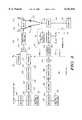
- FIG. 3generally depicts a transmitter of a base-station in CDMA communication with a mobile station using the orthogonal code assignment of the prior art.
- FIG. 4generally depicts a transmitter of a base-station in CDMA communication with a mobile station using the orthogonal code assignment in accordance with the present invention.
- FIG. 5generally depicts the assignment of orthogonal codes to implement forward link transmit diversity in the prior art.
- FIG. 6generally depicts the assignment of orthogonal codes to implement forward link transmit diversity in accordance with the invention.
- FIG. 7generally depicts an example of an assignment of IS-95A Walsh orthogonal codes to implement forward link transmit diversity in accordance with the invention.
- Different orthogonal codes on each antennaare used to spread a plurality of common pilot channels intended for transmission to a particular mobile station within a coverage area to implement forward link transmit diversity.
- the pilot signals transmitted via antennas to a common coverage areaare orthogonal to one another and thus do not degrade system performance.
- the use of different orthogonal codes for each pilot channelallows the mobile station to discern which pilot channel spread with a different orthogonal code includes corresponding traffic channel information. This allows forward link transmit diversity to be enable/disabled for each traffic channel independently based on conditions associated with the environment, the communications channel, etc. without a complete loss of information as seen by the mobile station.
- system interferenceis minimized.
- a method of controlling transmit diversity in a communication systemincludes the steps of transmitting common traffic channel information to a mobile station within a coverage area on a radio channel via spatially separated antennas and determining characteristics associated with the mobile station and related to the common traffic channel information transmission via the spatially separated antennas. The method then enables or disables a transmission via at least one of the spatially separated antennas based on the determined characteristics associated with the mobile station.
- the common traffic channel information transmitted to the mobile stationis accomplished via pilot channels spread with orthogonal codes and transmitted via the spatially separated antennas.
- the step of disabling a transmissionfurther comprises instructing the mobile station which pilot channel or pilot channels spread with orthogonal codes to decode.
- the step of determining characteristicsincludes determining when the mobile station requires a soft handoff, and specifically three-way soft handoff.
- the step of determining characteristicsalso includes determining when the radio channel transmitted to the mobile station experiences excessive delay spread. This is determined at a base station and the reciprocal properties of the radio channel are used to estimate the amount of delay spread.
- the step of determining the characteristics associated with the mobile stationalso includes determining the location of the mobile station within the coverage area. The determined location of the mobile station is correlated with information representing locations within the coverage area known to provide degraded coverage to the mobile station and the transmission via at least one of the spatially separated antennas is disabled when the mobile station is in a location within the coverage area known to provide degraded coverage to the mobile station.
- the information representing locations within the coverage area known to provide degraded coverage to the mobile stationis stored in a base station or a controller coupled to the base station.
- a mobile station in accordance with the inventiongenerally includes means for receiving common traffic channel information transmitted to the mobile station within a coverage area on a radio channel via spatially separated antennas and means for determining characteristics associated with the mobile station and related to the common traffic channel information transmission via the spatially separated antennas.
- the mobile stationfurther includes means for enabling or disabling a reception of at least one of the transmissions via the spatially separated antennas based on the determined characteristics associated with the mobile station.
- the means for receiving common traffic channel information transmitted to the mobile station within a coverage area on a radio channel via spatially separated antennasfurther includes means for receiving at least two pilot channels spread with orthogonal codes and transmitted via the spatially separated antennas.
- the means for disabling a receptionfurther includes means for receiving an instruction indicating to the mobile station which of the at least two pilot channel spread with orthogonal codes to decode.
- the means for determining the characteristics associated with the mobile stationfurther include means for determining the location of the mobile station within the coverage area and means for receiving information representing locations within the coverage area known to provide degraded coverage to the mobile station.
- the means for enabling or disabling a reception of at least one of the transmissions via the spatially separated antennasfurther includes means for enabling or disabling a reception of at least one of the transmissions via the spatially separated antennas based on a comparison between the location of the mobile station and the information representing locations within the coverage area known to provide degraded coverage to the mobile station.
- a base-station for controlling transmit diversity in a communication system in accordance with the inventionincludes means for transmitting common traffic channel information to a mobile station within a coverage area on a radio channel via spatially separated antennas and means for determining characteristics associated with the mobile station and related to the common traffic channel information transmission via the spatially separated antennas.
- the base stationfurther includes means for instructing the mobile station to enable or disable a transmission via at least one of the spatially separated antennas based on the determined characteristics associated with the mobile station.
- the means for transmitting common traffic channel information to the mobile stationis accomplished via pilot channels spread with orthogonal codes and transmitted via the spatially separated antennas.
- the means for instructing the mobile station to enable or disable a transmissionfurther includes means for instructing the mobile station which pilot channel or pilot channels spread with orthogonal codes to decode.
- the means for determining characteristicsfurther comprises means for determining when the mobile station requires a soft handoff, specifically three-way soft handoff.
- the means for determining characteristicsfurther includes means for determining when the radio channel transmitted to the mobile station experiences excessive delay spread which is determined at the base station and the reciprocal properties of the radio channel are used to estimate the amount of delay spread experienced by the mobile station. Also, the means for determining the characteristics associated with the mobile station further includes means for determining the location of the mobile station within the coverage area. The means for determining the characteristics associated with the mobile station further includes means for correlating the determined location of the mobile station with information representing locations within the coverage area known to provide degraded coverage to the mobile station.
- the means for instructing the mobile station to enable or disable a transmission via at least one of the spatially separated antennasfurther includes means for instructing the mobile station to enable or disable a transmission via at least one of the spatially separated antennas based on a comparison between the location of the mobile station and the information representing locations within the coverage area known to provide degraded coverage to the mobile station.
- FIG. 1generally depicts a 120° sectored cellular coverage area (cell) having dedicated pilot channels Pilot A-C transmitted throughout their respective sectors as is well known in the prior art.
- a base-station 103having three CDMA transceivers, is centered within the cell 100 at least one of which is capable of communicating to a mobile station 106 via a wireless air interface.
- the wireless air interfaceis compatible with the code-division multiple access (CDMA) cellular communication system defined in IS-95A.
- CDMAcode-division multiple access
- FIG. 2generally depicts a block diagram of the 120° sectored cellular coverage area of FIG. 1 supported by base-station 103 having two antennas 218, 222 to support forward link transmit diversity. Again, for the sake of simplicity, only the sector A from FIG. 1 is shown in FIG. 2.
- base-station 103 shown in FIG. 2is capable of communicating via CDMA communication channels to a mobile station 106. Coupled to base-station 103 is a controller 209 which performs, inter alia, transcoding and switching functions primarily related to the communication system. Controller 209 is coupled to a mobile switching center (MSC) 212 which primarily performs switching functions related to the land line network. Coupled to MSC 212 is the public switched telephone network (PSTN) 215 which includes, inter alia, originating subscribers, fax machines, etc. which are capable of originating and/or receiving communications to/from mobile station 106 within the CDMA communication system.
- PSTNpublic switched telephone network
- FIG. 2Also shown in FIG. 2 are a pair of antennas 218 and 222 which are capable of implementing forward link transmit diversity within the coverage area of sector A.
- a group of orthogonal codesare assigned to be transmitted via antennas 218 and 222.
- the orthogonal codesare Walsh codes.
- a pilot channel Pilot Ais transmitted via antenna 218 and 222 using Walsh code W X .
- this pilotis set to have a large amplitude compared to any other individual signals transmitted--perhaps 20% of the maximum total transmitted power.
- FIG. 5As can also be seen in FIG.
- all traffic channel information for N separate users(TCH N ) is transmitted to mobile station 106 via antennas 218 and 222 with Walsh codes which are different from the Walsh code used for the pilot channel Pilot A , but are the same for the transmissions via antenna 218 and 222.
- Walsh codesare shown as Walsh codes W i through W k . While the signals transmitted between antennas 218 and 222 are delayed in time, and as such a RAKE receiver within the mobile station 106 can resolve and combine these signals into a composite signal, the signals transmitted via antennas 218 and 222 are not orthogonal to one another and thus increase the amount of interference within the coverage area, sector A. As such, and as explained above, some of the potential advantage gained by implementing forward link transmit diversity is mitigated due to the increased interference presented by the copy of the original signal.
- FIG. 3generally depicts a transmitter 300 of a base-station in CDMA communication with a mobile station using the orthogonal code assignment of the prior art.
- information in the form of traffic channel bits 303input to a encoder 304 via a processor 305 at a particular bit rate (e.g. 9.6 kilobits/second).
- the processor 305primarily receives the traffic channel bits 303 from the interface 309 which is coupled to a controller (not shown in FIG. 3).
- the processor 305is also coupled to a block designated related functions 307, where functions including call processing, link establishment, and other general functions related to establishing and maintaining cellular communications are performed.
- the traffic channel bits 303include either voice information, data information, or a combination of the two.
- Encoder 304encodes the traffic channel bits 303 into data symbols 306 at a fixed encoding rate (1/r) with an encoding algorithm which facilitates subsequent maximum likelihood decoding of the data symbols into data bits (e.g. convolutional or block coding algorithms).
- the data symbols 306are input into an interleaver 308 which organizes the data symbols 306 into blocks (i.e., frames) and block interleaves the input data symbols 306 at the symbol level.
- the data symbolsare individually input into a matrix which defines a predetermined size block of data symbols.
- the data symbolsare input into location in the matrix so that the matrix is filled in a column by column sequence and are individually output from locations in the matrix so that the matrix is emptied in a row by row sequence.
- the matrixis a rectangular matrix having an integer number of rows and columns which are chosen to increase the output interleaving distance between the consecutively input non-interleaved data symbols.
- the resultis interleaved data symbols 309 which are output by the interleaver 308 at the same data symbol rate that they were input (e.g., 19.2 kilosymbols/second).
- the predetermined size of the block of data symbols defined by the matrixis derived from the maximum number of data symbols which can be transmitted at a coded bit rate within a predetermined length transmission block.
- the predetermined size of the block of data symbolsis 19.2 kilo symbols/second multiplied by 20 milliseconds (ms), resulting in 384 data symbols which defines a 16 by 24 matrix.
- the encoded, interleaved data symbols 309are next input to a spreader 312 which convolves the interleaved symbols 309 with an orthogonal spreading sequence.
- the orthogonal spreading sequenceis a signal which is the product of two signals; the first signal is a QPSK pseudorandom sequence whose time offset is known and the second signal is an orthogonal spreading code such as a Walsh code W i .
- W ian orthogonal spreading code
- the spreader 312outputs QPSK chips at a rate which is the product of the input rate from interleaver 308 and the length of the orthogonal spreading sequence (e.g., orthogonal spreading sequence of length 64 would be a 64 bit length Walsh Code). This would result in an output rate of the spreader 312 of 1.2288 megachips/second (i.e., 19.2 kilosymbols/second ⁇ 64).
- spreader 312accomplishes the spreading associated with the traffic channel.
- the encoder 304, interleaver 308 and spreader 312comprise a single traffic channel generator 302.
- traffic channel generator 302would be duplicated for each traffic channel and its output would be summed by the summer 314 along with the QPSK chips from the spreader 310.
- Spreader 310accomplishes the spreading for the pilot channel. As the pilot channel transfers no information bits, no data input from the processor 305 is required. In the preferred embodiment, the information which is spread to form the pilot channel consists of a stream of data comprised of all 0's.
- the summed QPSK chipsare output from the summer 314 at a rate of 1.2288 megachips/second, and are input into the transmitter portion 316 of the transmitter 300.
- the transmitter portion 316prepares the summed QPSK chips for transmission over a communication channel by upconverting them to the appropriate transmit frequency. Following upconversion, the signal is bandpass filtered to remove unwanted sideband energy and then is output from the transmitter portion 316.
- the modulated signal from the transmitter portion 316is provided to an antenna 318 for transmission over the radio communications path 330.
- the signal from transmitter portion 316is also directed to a delay circuit 320 which delays the modulated signal, where it is then provided to antenna 322 for transmission over the radio communication path 332.
- a receiver 390receives the sum of both transmitted spread-spectrum signals from the radio communication paths 330 and 332 through antenna 352 and is passed to the demodulator 354.
- the demodulator 354filters the input signal to remove unwanted adjacent frequency signals after down-conversion from the transmit frequency and sampling at a predetermined rate (e.g., 1.2288 megasamples/second).
- the QPSK sampled signal from demodulator 354is despread by the despreader 364 by correlating the received sampled signals with the despreading code, where the despreading code is a copy of the original spreading sequence.
- the original orthogonal spreading sequenceis the product of two signals; the first signal is a QPSK pseudorandom sequence whose time offset is known and the second signal is an orthogonal spreading code such as Walsh code W i .
- the resulting despread sampled signal 365is sampled at a predetermined rate, for example, 19.2 kilosamples/second, so that a sequence of 64 samples of the received spread-spectrum signal is despread.
- This signalis represented by a single complex (amplitude and phase) data sample and output to a coherent detector 368 for coherent detection.
- the output of demodulator 354is also fed to the pilot recovery circuit 362 wherein a process similar to that performed by the despreader 364 is completed, except that the Walsh code W x is used for recovery rather than Walsh code W i .
- Output from both the pilot recovery circuit 362 and the despreader 364are input to the coherent detector 368 which takes the complex conjugate of the output of the pilot recovery circuit 362 and multiplies this by the output of the despreader 364.
- the real part of the solutionis passed as an output of coherent detector 368 (the imaginary part of the complex multiply is discarded).
- the output of the demodulator 354is also provided to a searcher 350 which searches for all signals spread with Walsh code W x which are generated by base-station transmitter 300. In this instance the searcher 350 would find two signals, one from radio communication path 330 and the other from radio communications path 332. With this information, the search 350 assigns a first finger RAKE receiver 360 and a second finger RAKE receiver 370 to each of these paths. Both rake finger receivers 360 and 370 are identical in operation. The output of the RAKE receivers 360 and 370 are summed by summer 375 and the output of the summer 375 is provided to de-interleaver 380, which essentially "undoes" the interleaving process performed by the interleaver 308.
- the data symbolsare individually input into a matrix which is the same size as the matrix in the interleaver 308.
- the data symbolsare input into a location in the matrix such that the matrix is filled in a row by row sequence and the data symbols are individually output from locations in the matrix such that the matrix is emptied in a column by column sequence.
- the de-interleaved soft decision data 381 output from the de-interleaver 380are input to a decoder 382 which uses well known maximum likelihood sequence estimation (MLSE) decoding techniques to generate estimated traffic channel data bits 383.
- the MLSE decoding techniquesmay be augmented by using an algorithm which is substantially similar to a Viterbi decoding algorithm.
- the decoder 382uses a group of the individual soft decision data 381 to form a set of soft decision transition metrics for use at each particular time state of the MLSE decoder 382.
- the number of soft decision data 364 in the group used to form each set of soft decision transition metricscorresponds to the number of data symbols 306 at the output of the convolutional encoder 304 generated from each input data bit 303.
- the number of soft decision transition metrics in each setis equal to two raised to the power of the number of soft decision data 364 in each group. For example, when a 1/2 convolutional encoder is used in the transmitter 300, two data symbols 306 are generated from each input data bit 303. Thus, decoder 366 uses groups of two individual soft decision data 381 to form four soft decision transition metrics for use at each time state in the MLSE decoder 382.
- the estimated traffic channel data bits 383are generated at a rate related to the rate at which the soft decision data 381 are input to the decoder 382 and also the fixed rate used to originally encode the traffic channel bits 303.
- the estimated traffic channel bits 383are output at a rate of 9600 bits/second.
- the estimated traffic channel bits 383are input into a processor 384 which, together with a related functions block 386, present the estimated traffic channel bits 383 in a form suitable for use by the user of the mobile station.
- FIG. 4generally depicts a transmitter of a base-station in CDMA communication with a mobile station using the orthogonal code assignment in accordance with the present invention. Those blocks between FIG. 3 and FIG. 4 which have common functionality also have common numbering.
- the blocks up to the interleaver 308are similar in function to the prior art transmitter 300 of FIG. 3, unless stated otherwise below.
- the interleaved data symbols 309 output from the interleaver 308 in FIG. 4are input into two spreaders, spreader 312 and spreader 413.
- Each of these spreaders 312 and 413convolves the interleaved symbols 309 with their orthogonal spreading sequence, namely Walsh code W i and Walsh code W A respectively.
- the spreading with the orthogonal spreading sequences(Walsh codes) is functionally equivalent as described above with reference to FIG. 3.
- the encoder 304, interleaver 308 and two spreaders 312 and 413comprise a duplicate traffic channel generator 402.
- Walsh code assignment block 403.divides a predetermined set of orthogonal codes into a plurality of subsets of orthogonal codes and assigns the subsets of orthogonal codes according to predetermined criterion.
- the predetermined criterionincludes assigning the subsets of orthogonal codes to certain antennas servicing a common coverage area certain or to certain antennas within an antenna array.
- Each of the spreaders 312 and 413outputs QPSK chips at a rate of 1.2288 megachips/second (i.e., 19.2 kilosymbols/second ⁇ 64).
- the spreader 310, summing node 314 and transmitter portion 314 of FIG. 4operate functionally equivalent to the corresponding blocks of FIG. 3.
- the spreader 411, summing node 415 and transmitter portion 417also operate functionally equivalent to their corresponding blocks of FIG. 3.
- Important to noteis that, unlike the prior art transmitter 300 shown in FIG.
- each of the spreaders 310 and 411 used for spreading the pilot channeluses a spreading sequence (Walsh code W x and Walsh code W y , respectively) which is orthogonal to one another in accordance with the invention.
- a receiver 490receives the sum of both transmitted spread-spectrum signals 330 and 432 from the radio communication paths 330 and 432 via antenna 352 and is passed to demodulator 354 which functions as described above with reference to FIG. 3.
- the QPSK sampled signal output from demodulator 354is despread and detected by first finger RAKE receiver 360 as described above for FIG. 3.
- the QPSK sampled signal output from demodulator 354is despread and detected by a second finger RAKE receiver 470 as essentially described above for FIG. 3, except that the QPSK sampled signal output from demodulator 354 entering this RAKE receiver 470 is despread by Walsh code W A (for the traffic channel) and Walsh code W y (for the pilot channel). Note that this differs from the prior art receiver 390 shown in FIG. 3 in that each of the RAKE receivers 360-370 have the pilot channel despread by the same Walsh code W x and the traffic channel despread by the same Walsh code W i .
- the searcher 450searches for all signals spread with Walsh code W x transmitted by transmitter 400; in this instance, the searcher 450 would find one signal which corresponds to radio communication path 330. With this information, the searcher 450 assigns first finger RAKE receiver 360 to communication path 330 with pilot channel Walsh code W x and traffic channel Walsh code W i . A similar process is performed by the searcher 450 for signals spread with Walsh code W y transmitted by transmitter 400. In this instance, second finger RAKE receiver 470 is assigned to communication path 432 with pilot channel Walsh code Wy and traffic channel Walsh code W A .
- Having two pilot channels spread by different, orthogonal spreading sequences within a common coverage areaallows one of the pilot channels to be used as the primary pilot channel for all mobile stations within the coverage area (as in the prior art) while the other pilot channel is used as a secondary pilot channel.
- the primary pilot channelwhich is used for acquisition and neighbor measurements by mobile station 106, is at a fixed, relatively high signal power level while the secondary pilot channel is at a much lower signal power level. This further acts to reduce unnecessary system interference when implementing forward link diversity in accordance with the invention.
- a correction prior to summing in summer 375is required such that the signals entering the summer 375 from each of the RAKE receivers 360 and 470 are at substantially the same power level.
- One way to accomplish thisis by appropriately reducing, via an attenuator, the signals exiting Rake receiver 360 or Rake receiver 470 in accordance with the power level difference at the transmitter 400. All processing after the summer 375 is the same as described above with reference to FIG. 3.
- FIG. 6generally depicts the assignment of orthogonal codes in the preferred embodiment to implement forward link transmit diversity in accordance with the invention.
- each antenna 218 and 222have a separate group of dedicated Walsh codes assigned thereto.
- a primary pilot channel transmitted via antenna 218is spread by Walsh code W x while a secondary pilot channel transmitted via antenna 222 is spread by a different Walsh code W y .
- all traffic channels for each of N separate usersmay each have separate Walsh codes assigned thereto on the secondary antenna 222.
- TCH Nthe same information.
- mobile station 106design of and knowledge contained within mobile station 106 is such that it properly performs a demodulation technique appropriate to whether a diversity signal is being transmitted or not. This includes full knowledge of what codes are used for all the pilots and traffic channels on each of the antennas. This may be facilitated through the use of messaging of information between the base-station 103 and mobile station 106. Methods to implement signaling of this information are known and are readily accomplished with messages provided in the IS-95 standard.
- implementation of forward link transmit diversity in accordance with the inventionis the use of a different orthogonal spreading sequence to spread common pilot channels and TCHs for transmission on a second antenna.
- thiscan be accomplished by using two Walsh codes on antenna 218 which are not used on antenna 222.
- Walsh codesfor the IS-95A example is shown in FIG. 7.
- antenna 218is assigned Walsh code 63 to spread the pilot channel Pilot A and thus act as a pilot channel for all mobile stations that are in the transmit diversity mode, while Walsh code 62 is used to spread the TCH information intended for mobile station 106 (designated TCH 106 in FIG. 7).
- Antenna 222is then assigned Walsh code 0 to spread the pilot channel Pilot A and Walsh code 1 to spread the TCH 106 information intended for mobile station 106.
- Walsh code 0in this example, thus acts as the common pilot channel for all mobile stations being served by or performing mobile assisted handoff (MAHO) on that coverage area, while Walsh code 1 conveys the TCH information to the particular mobile station.
- MAHOmobile assisted handoff
- any number of antennascan be assigned their own Walsh codes, e.g. as in an antenna array.
- eight antennas within an antenna arraycan be assigned eight Walsh codes which are themselves not assigned to any other antenna, and these eight Walsh codes can then be used to spread a pilot channel for each respective antenna, for example Pilot A .
- Mobile station 106could then be assigned a single Walsh code for its traffic channel information TCH 106 that would then be transmitted on all of the antenna elements within the array. By setting the relative phases and amplitudes of this single Walsh code used to spread the TCH 106 information on the individual antenna elements, beamforming to direct transmit power directly at mobile station 106 is performed in accordance with the invention.
- base-station 103informs mobile station 106 of the relative amplitudes and phases of the TCH 106 Walsh code that base-station 103 used to form the beam toward mobile station 106. This is accomplished by transmitting an appropriate message from base-station 103 to mobile station 106 including such information. Mobile station 106 would then determine the amplitude and phase of each of the pilot channels Pilot A spread with different Walsh codes on the individual antennas. Given the relative amplitudes and phases of the pilot channels Pilot A spread with different Walsh codes and the message from base-station 103 which includes the relative amplitudes and phases of the TCH 106 Walsh code, mobile station 106 calculates a difference vector for each different pilot channel Walsh code. The sum of all of these difference vectors is then used by the mobile station 106 to perform coherent demodulation.
- Adequate signal to interference ratio necessary to improve reusemay be obtained when the same traffic channel Walsh code is used for multiple mobiles in the same sector by forming separate beams on each of the mobiles and transmitting them over the same antenna array.
- the pilot channel/Walsh code for each antennacould be shared among all mobile stations within the coverage area of interest (for example, sector A of FIG. 2).
- Another benefit resulting from the ability to assign separate pilot Walsh codes to a particular antennais the ability to control the use of forward link transmit diversity.
- the only "control" availableis to either transmit nothing to the mobile station 106 or transmit via both antenna 218 and antenna 222. This is due to the fact that some RAKE combining algorithms weight the combining strictly on the amount of pilot signal level received. Therefore, if multiple antennas are used having the pilot signal but no proper traffic channel is present, undesirable noise may be combined causing system degradation. However, there are certain modes and/or certain characteristics which occur during a communication where the transmission of both the original signal and its delayed version via antennas 218 and 222 is not beneficial.
- any more than three (3) rays transmitted to only a single mobile station 106means that excess (unused) power is being transmitted by base-station 103, which degrades system performance.
- the Walsh code assignment of FIG. 6 in accordance with the inventionis implemented, however, the use of forward link transmit diversity is controllable since the mobile station 106 can now be instructed, via appropriate messaging, as to which pilot channel Pilot A to listen via the different Walsh code assignment. As such, in the three-way handoff example described above, one of the signals being transmitted via forward link transmit diversity is removed since it does not help the mobile station 106 to better decode the signal.
- the addition of another ray in the forward linkmay only serve to degrade overall system performance. This information is readily available from the receiver (not shown) of the base-station 103 and can be input into the related functions block 407 for use by the Walsh code assignment block 403 of FIG. 4.
- These modes and/or characteristicsinclude the receive signal strength as determined by the mobile station 106 (or the base-station 103 is the transmission paths are assumed to be reciprocal), the pilot measurement information obtained in a pilot strength measurement message (PSMM), and the delay of a signal received at the mobile station 106. This last characteristic gives a direct indication of the distance of the mobile station 106 from the base-station 103 which could then be used to determine the high likelihood of an excessive amount of delay spread.
- PSMMpilot strength measurement message
- Still another mode and/or characteristic to control the use of forward link transmit diversitycould be the location of the mobile station 106.
- a coverage areasuch as sector A could be pretested to determine the locations within the coverage area where forward link transmit diversity is known to provide degraded coverage to the mobile station.
- This pre-test informationrepresenting these locations can then be locally stored at the base-station 103 or at a central facility, such as the controller 209.
- the base-station 103determines the location of the mobile station 106, a comparison can be made to the stored information to determine if the mobile station 106 is in one of the "known-bad" locations.
- forward link transmit diversitywill not help the mobile station 106 and it will thus be disabled until the mobile station 106 moves into a more suitable area within the coverage area; if the mobile station is not in a "known-bad” location, then forward link transmit diversity is enabled.
- the mobile station 106could be equipped to determine its own location and provide this information to the base-station 103 for the comparison.
- One such mechanism for the mobile station 106 to determine its own locationis via the use of the Global Positioning System (GPS) or the like. If the mobile station 106 is capable of determining its own position, the pre-test information could also be downloaded to the mobile station 106 and stored locally therein. In this configuration, the mobile station 106 itself could determine that it is in a "known-bad” or "known-good” location, and disable/enable reception of one of the pilot channels spread with orthogonal spreading codes accordingly in accordance with the invention.
- GPSGlobal Positioning System
Landscapes
- Engineering & Computer Science (AREA)
- Computer Networks & Wireless Communication (AREA)
- Signal Processing (AREA)
- Mobile Radio Communication Systems (AREA)
Abstract
Description
Claims (17)
Priority Applications (1)
| Application Number | Priority Date | Filing Date | Title |
|---|---|---|---|
| US08/904,042US6141542A (en) | 1997-07-31 | 1997-07-31 | Method and apparatus for controlling transmit diversity in a communication system |
Applications Claiming Priority (1)
| Application Number | Priority Date | Filing Date | Title |
|---|---|---|---|
| US08/904,042US6141542A (en) | 1997-07-31 | 1997-07-31 | Method and apparatus for controlling transmit diversity in a communication system |
Publications (1)
| Publication Number | Publication Date |
|---|---|
| US6141542Atrue US6141542A (en) | 2000-10-31 |
Family
ID=25418442
Family Applications (1)
| Application Number | Title | Priority Date | Filing Date |
|---|---|---|---|
| US08/904,042Expired - LifetimeUS6141542A (en) | 1997-07-31 | 1997-07-31 | Method and apparatus for controlling transmit diversity in a communication system |
Country Status (1)
| Country | Link |
|---|---|
| US (1) | US6141542A (en) |
Cited By (61)
| Publication number | Priority date | Publication date | Assignee | Title |
|---|---|---|---|---|
| US6285861B1 (en)* | 1999-06-14 | 2001-09-04 | Qualcomm Incorporated | Receiving station with interference signal suppression |
| US6377967B1 (en)* | 1998-08-12 | 2002-04-23 | Northrop Grumman Corporation | Efficient digital integration technique filter |
| US20020072393A1 (en)* | 2000-12-11 | 2002-06-13 | Mcgowan Neil | Antenna systems with common overhead for CDMA base stations |
| US20020111174A1 (en)* | 2000-11-16 | 2002-08-15 | Judson Bruce A. | Method and apparatus for using position location to direct narrow beam antennas |
| US6459884B1 (en)* | 1998-07-22 | 2002-10-01 | Oki Electric Industry Co, Ltd. | Method of and apparatus for estimating the characteristics of a radio channel on which a pilot channel partially defective is conveyed |
| US6466558B1 (en)* | 1999-06-14 | 2002-10-15 | Qualcomm Incorporated | Selection mechanism for signal combining methods |
| US6473466B1 (en)* | 1997-12-08 | 2002-10-29 | Hitachi Denshi Kabushiki Kaisha | Data transmitting method and data transmitting apparatus accompanied with a plurality of transmitting of receiving antennas |
| US6542484B1 (en)* | 1998-05-15 | 2003-04-01 | Telefonaktiebolaget Lm Ericsson (Publ) | Code allocation for radiocommunication systems |
| US20030081656A1 (en)* | 1999-04-19 | 2003-05-01 | Lucent Technologies Inc. | Methods and apparatus for downlink diversity in CDMA using Walsh codes |
| US6564062B1 (en)* | 2000-06-09 | 2003-05-13 | Denso Corporation | Pilot search to determine processor loading |
| US20030124995A1 (en)* | 2000-08-10 | 2003-07-03 | Yoshinori Tanaka | Transmitting diversity communications apparatus |
| US6609003B1 (en)* | 1998-05-13 | 2003-08-19 | Samsung Electronics Co., Ltd. | Handoff method in a mobile communication system supporting transmission diversity |
| US20030174666A1 (en)* | 1998-12-04 | 2003-09-18 | Wallace Mark S. | Method and apparatus for providing wireless communication system synchronization |
| US6721339B2 (en)* | 1999-08-17 | 2004-04-13 | Lucent Technologies Inc. | Method of providing downlink transmit diversity |
| US20040109515A1 (en)* | 2002-12-04 | 2004-06-10 | Motorola, Inc. | Excess delay spread detection method for multi-carrier communication systems |
| US6754473B1 (en)* | 1999-10-09 | 2004-06-22 | Samsung Electronics Co., Ltd. | Apparatus and method for providing closed-loop transmit antenna diversity in a mobile communication system |
| US20040180695A1 (en)* | 2001-09-25 | 2004-09-16 | Hiroyasu Sano | Site diversity transmission/reception apparatus, base station, and mobile station |
| US20050032520A1 (en)* | 2001-02-16 | 2005-02-10 | Walter Muller | Estimating signal strength measurements in a telecommunications system |
| US20050048933A1 (en)* | 2003-08-25 | 2005-03-03 | Jingxian Wu | Adaptive transmit diversity with quadrant phase constraining feedback |
| US20050083875A1 (en)* | 1998-03-04 | 2005-04-21 | Nec Corporation | Cellular system |
| US20050117520A1 (en)* | 2002-09-13 | 2005-06-02 | Kenichi Miyoshi | Radio transmission device and radio transmission method |
| US6961545B2 (en) | 2001-04-09 | 2005-11-01 | Atheros Communications, Inc. | Method and system for providing antenna diversity |
| US20060025152A1 (en)* | 2004-07-28 | 2006-02-02 | Pantech Co., Ltd | Apparatus and method of controlling diversity reception for mobile communication terminal combined with satellite DMB receiver |
| WO2006029362A1 (en)* | 2004-09-09 | 2006-03-16 | Agere Systems Inc. | Method and apparatus for communicating orthogonal pilot tones in a multiple antenna communication system |
| US7079510B1 (en)* | 1999-02-19 | 2006-07-18 | Nokia Corporation | Code allocation in connection with soft handover in CDMA system |
| US20060209808A1 (en)* | 1997-09-08 | 2006-09-21 | Lundby Stein A | Method and apparatus for providing orthogonal spot beams, sectors, and picocells |
| US7263335B2 (en) | 2004-07-19 | 2007-08-28 | Purewave Networks, Inc. | Multi-connection, non-simultaneous frequency diversity in radio communication systems |
| WO2007128199A1 (en)* | 2006-04-28 | 2007-11-15 | Huawei Technologies Co., Ltd. | Pilot multiplexing method, apparatus and radio communication system of multiple antennas |
| US20080064335A1 (en)* | 1999-02-16 | 2008-03-13 | Mitsubishi Denki Kabushiki Kaisha | Radio Communication System, a Transmitter and a Receiver |
| US7460839B2 (en) | 2004-07-19 | 2008-12-02 | Purewave Networks, Inc. | Non-simultaneous frequency diversity in radio communication systems |
| US7603128B1 (en)* | 2003-06-09 | 2009-10-13 | Sprint Spectrum L.P. | System and method for wireless distribution of location-based information in an enclosure |
| US20110043640A1 (en)* | 2009-08-18 | 2011-02-24 | Arcom Digital, Llc | Methods and apparatus for detecting and locating leakage of digital signals |
| US20110080876A1 (en)* | 2009-10-02 | 2011-04-07 | Sharp Laboratories Of America, Inc. | Transmission diversity scheme on physical uplink control channel (pucch) with ack/nack differentiation |
| US20110080880A1 (en)* | 2009-10-02 | 2011-04-07 | Sharp Laboratories Of America, Inc. | Transmission diversity scheme on physical uplink control channel (pucch) with ack/nack differentiation |
| US7986742B2 (en) | 2002-10-25 | 2011-07-26 | Qualcomm Incorporated | Pilots for MIMO communication system |
| US8134976B2 (en) | 2002-10-25 | 2012-03-13 | Qualcomm Incorporated | Channel calibration for a time division duplexed communication system |
| US8145179B2 (en) | 2002-10-25 | 2012-03-27 | Qualcomm Incorporated | Data detection and demodulation for wireless communication systems |
| US8169944B2 (en) | 2002-10-25 | 2012-05-01 | Qualcomm Incorporated | Random access for wireless multiple-access communication systems |
| US8194770B2 (en) | 2002-08-27 | 2012-06-05 | Qualcomm Incorporated | Coded MIMO systems with selective channel inversion applied per eigenmode |
| US8203978B2 (en) | 2002-10-25 | 2012-06-19 | Qualcomm Incorporated | Multi-mode terminal in a wireless MIMO system |
| US8208364B2 (en) | 2002-10-25 | 2012-06-26 | Qualcomm Incorporated | MIMO system with multiple spatial multiplexing modes |
| US8218609B2 (en) | 2002-10-25 | 2012-07-10 | Qualcomm Incorporated | Closed-loop rate control for a multi-channel communication system |
| US8320301B2 (en) | 2002-10-25 | 2012-11-27 | Qualcomm Incorporated | MIMO WLAN system |
| US8358714B2 (en) | 2005-06-16 | 2013-01-22 | Qualcomm Incorporated | Coding and modulation for multiple data streams in a communication system |
| US8417264B1 (en) | 2009-05-14 | 2013-04-09 | Spring Spectrum L.P. | Method and apparatus for determining location of a mobile station based on locations of multiple nearby mobile stations |
| EP2068479A4 (en)* | 2006-10-03 | 2013-09-04 | Ntt Docomo Inc | BASE STATION DEVICE |
| US8570988B2 (en) | 2002-10-25 | 2013-10-29 | Qualcomm Incorporated | Channel calibration for a time division duplexed communication system |
| US8650605B2 (en) | 2012-04-26 | 2014-02-11 | Arcom Digital, Llc | Low-cost leakage detector for a digital HFC network |
| US20140269638A1 (en)* | 2005-12-20 | 2014-09-18 | Qualcomm Incorporated | Methods and systems for providing enhanced position location in wireless communications |
| US20140273874A1 (en)* | 2013-03-15 | 2014-09-18 | Thorsten Clevorn | Communications terminal, a network component, a method for transmitting a signal, and a method for providing feedback information to a communications terminal |
| US8855226B2 (en) | 2005-05-12 | 2014-10-07 | Qualcomm Incorporated | Rate selection with margin sharing |
| US8873365B2 (en) | 2002-10-25 | 2014-10-28 | Qualcomm Incorporated | Transmit diversity processing for a multi-antenna communication system |
| US8891387B2 (en) | 2010-05-03 | 2014-11-18 | Qualcomm Incorporated | UE based conditional enabling of ULTD |
| US9154274B2 (en) | 2002-10-25 | 2015-10-06 | Qualcomm Incorporated | OFDM communication system with multiple OFDM symbol sizes |
| US9473269B2 (en) | 2003-12-01 | 2016-10-18 | Qualcomm Incorporated | Method and apparatus for providing an efficient control channel structure in a wireless communication system |
| US9538392B2 (en) | 2000-12-11 | 2017-01-03 | Apple Inc. | Antenna systems with common overhead for CDMA base stations |
| US9551785B1 (en) | 1999-04-07 | 2017-01-24 | James L. Geer | Method and apparatus for the detection of objects using electromagnetic wave attenuation patterns |
| US11438025B2 (en)* | 2018-09-18 | 2022-09-06 | Roku, Inc. | Audio synchronization of a dumb speaker and a smart speaker using a spread code |
| US11558579B2 (en) | 2018-09-18 | 2023-01-17 | Roku, Inc. | Wireless audio synchronization using a spread code |
| US20230093484A1 (en)* | 2021-09-23 | 2023-03-23 | Apple Inc. | Systems and methods for de-correlating coded signals in dual port transmissions |
| US11671139B2 (en) | 2018-09-18 | 2023-06-06 | Roku, Inc. | Identifying electronic devices in a room using a spread code |
Citations (9)
| Publication number | Priority date | Publication date | Assignee | Title |
|---|---|---|---|---|
| US4490830A (en)* | 1981-07-22 | 1984-12-25 | Nippon Electric Co., Ltd. | Radio signal transmission system including a plurality of transmitters for transmitting a common signal |
| US5625876A (en)* | 1993-10-28 | 1997-04-29 | Qualcomm Incorporated | Method and apparatus for performing handoff between sectors of a common base station |
| US5652764A (en)* | 1995-01-17 | 1997-07-29 | Kabushiki Kaisha Toshiba | Radio communication system |
| US5771461A (en)* | 1996-06-28 | 1998-06-23 | Motorola, Inc. | Method and apparatus for power control of a first channel based on a signal quality of a second channel |
| US5781541A (en)* | 1995-05-03 | 1998-07-14 | Bell Atlantic Network Services, Inc. | CDMA system having time-distributed transmission paths for multipath reception |
| US5812935A (en)* | 1993-04-17 | 1998-09-22 | Hughes Electronics | Cellular system employing base station transmit diversity according to transmission quality level |
| US5926503A (en)* | 1997-08-27 | 1999-07-20 | Motorola, Inc. | DS-CDMA receiver and forward link diversity method |
| US6023615A (en)* | 1995-11-29 | 2000-02-08 | Motorola, Inc. | Method for controlling a diversity receiver apparatus in a radio subscriber unit |
| US6038263A (en)* | 1997-07-31 | 2000-03-14 | Motorola, Inc. | Method and apparatus for transmitting signals in a communication system |
- 1997
- 1997-07-31USUS08/904,042patent/US6141542A/ennot_activeExpired - Lifetime
Patent Citations (9)
| Publication number | Priority date | Publication date | Assignee | Title |
|---|---|---|---|---|
| US4490830A (en)* | 1981-07-22 | 1984-12-25 | Nippon Electric Co., Ltd. | Radio signal transmission system including a plurality of transmitters for transmitting a common signal |
| US5812935A (en)* | 1993-04-17 | 1998-09-22 | Hughes Electronics | Cellular system employing base station transmit diversity according to transmission quality level |
| US5625876A (en)* | 1993-10-28 | 1997-04-29 | Qualcomm Incorporated | Method and apparatus for performing handoff between sectors of a common base station |
| US5652764A (en)* | 1995-01-17 | 1997-07-29 | Kabushiki Kaisha Toshiba | Radio communication system |
| US5781541A (en)* | 1995-05-03 | 1998-07-14 | Bell Atlantic Network Services, Inc. | CDMA system having time-distributed transmission paths for multipath reception |
| US6023615A (en)* | 1995-11-29 | 2000-02-08 | Motorola, Inc. | Method for controlling a diversity receiver apparatus in a radio subscriber unit |
| US5771461A (en)* | 1996-06-28 | 1998-06-23 | Motorola, Inc. | Method and apparatus for power control of a first channel based on a signal quality of a second channel |
| US6038263A (en)* | 1997-07-31 | 2000-03-14 | Motorola, Inc. | Method and apparatus for transmitting signals in a communication system |
| US5926503A (en)* | 1997-08-27 | 1999-07-20 | Motorola, Inc. | DS-CDMA receiver and forward link diversity method |
Non-Patent Citations (4)
| Title |
|---|
| "Fading Resistant Modulation Using Several Transmitter Antennas", Victor M. DaSilva and Elvino S. Sousa, IEEE Transactions on Communications, Ovl. 45, No. 10, Oct., 1997. |
| Fading Resistant Modulation Using Several Rransmitter Antennas Victor M. DaSlviva and Elivno S. Sousa, pp. (1 5), Aug. 1997.* |
| Fading- Resistant Modulation Using Several Rransmitter Antennas Victor M. DaSlviva and Elivno S. Sousa, pp. (1-5), Aug. 1997. |
| Fading Resistant Modulation Using Several Transmitter Antennas , Victor M. DaSilva and Elvino S. Sousa, IEEE Transactions on Communications, Ovl. 45, No. 10, Oct., 1997.* |
Cited By (120)
| Publication number | Priority date | Publication date | Assignee | Title |
|---|---|---|---|---|
| US7680084B2 (en)* | 1997-09-08 | 2010-03-16 | Qualcomm Incorporated | Method and apparatus for providing orthogonal spot beams, sectors, and picocells |
| US20060209808A1 (en)* | 1997-09-08 | 2006-09-21 | Lundby Stein A | Method and apparatus for providing orthogonal spot beams, sectors, and picocells |
| US6473466B1 (en)* | 1997-12-08 | 2002-10-29 | Hitachi Denshi Kabushiki Kaisha | Data transmitting method and data transmitting apparatus accompanied with a plurality of transmitting of receiving antennas |
| US20050083875A1 (en)* | 1998-03-04 | 2005-04-21 | Nec Corporation | Cellular system |
| US7072325B1 (en)* | 1998-03-04 | 2006-07-04 | Nec Corporation | Cellular system |
| US7609679B2 (en)* | 1998-03-04 | 2009-10-27 | Nec Corporation | Cellular system |
| US6609003B1 (en)* | 1998-05-13 | 2003-08-19 | Samsung Electronics Co., Ltd. | Handoff method in a mobile communication system supporting transmission diversity |
| US6542484B1 (en)* | 1998-05-15 | 2003-04-01 | Telefonaktiebolaget Lm Ericsson (Publ) | Code allocation for radiocommunication systems |
| US6459884B1 (en)* | 1998-07-22 | 2002-10-01 | Oki Electric Industry Co, Ltd. | Method of and apparatus for estimating the characteristics of a radio channel on which a pilot channel partially defective is conveyed |
| US6377967B1 (en)* | 1998-08-12 | 2002-04-23 | Northrop Grumman Corporation | Efficient digital integration technique filter |
| US7391759B2 (en)* | 1998-12-04 | 2008-06-24 | Qualcomm Incorporated | Method and apparatus for providing wireless communication system synchronization |
| US20030174666A1 (en)* | 1998-12-04 | 2003-09-18 | Wallace Mark S. | Method and apparatus for providing wireless communication system synchronization |
| US20080064335A1 (en)* | 1999-02-16 | 2008-03-13 | Mitsubishi Denki Kabushiki Kaisha | Radio Communication System, a Transmitter and a Receiver |
| US8027649B2 (en)* | 1999-02-16 | 2011-09-27 | Mitsubishi Denki Kabushiki Kaisha | Radio communication system, a transmitter and a receiver |
| US7929922B2 (en)* | 1999-02-16 | 2011-04-19 | Mitsubishi Denki Kabushiki Kaisha | Radio communication system, a transmitter and a receiver |
| US20080064428A1 (en)* | 1999-02-16 | 2008-03-13 | Mitsubishi Denki Kabushiki Kaisha | Radio Communication System, a Transmitter and a Receiver |
| US7079510B1 (en)* | 1999-02-19 | 2006-07-18 | Nokia Corporation | Code allocation in connection with soft handover in CDMA system |
| US9551785B1 (en) | 1999-04-07 | 2017-01-24 | James L. Geer | Method and apparatus for the detection of objects using electromagnetic wave attenuation patterns |
| US20030081656A1 (en)* | 1999-04-19 | 2003-05-01 | Lucent Technologies Inc. | Methods and apparatus for downlink diversity in CDMA using Walsh codes |
| US7400614B2 (en)* | 1999-04-19 | 2008-07-15 | Lucent Technologies Inc. | Methods and apparatus for downlink diversity in CDMA using Walsh codes |
| US6466558B1 (en)* | 1999-06-14 | 2002-10-15 | Qualcomm Incorporated | Selection mechanism for signal combining methods |
| US6285861B1 (en)* | 1999-06-14 | 2001-09-04 | Qualcomm Incorporated | Receiving station with interference signal suppression |
| US6700880B2 (en) | 1999-06-14 | 2004-03-02 | Qualcomm Incorporated | Selection mechanism for signal combining methods |
| US6721339B2 (en)* | 1999-08-17 | 2004-04-13 | Lucent Technologies Inc. | Method of providing downlink transmit diversity |
| US6754473B1 (en)* | 1999-10-09 | 2004-06-22 | Samsung Electronics Co., Ltd. | Apparatus and method for providing closed-loop transmit antenna diversity in a mobile communication system |
| US6564062B1 (en)* | 2000-06-09 | 2003-05-13 | Denso Corporation | Pilot search to determine processor loading |
| US20030124995A1 (en)* | 2000-08-10 | 2003-07-03 | Yoshinori Tanaka | Transmitting diversity communications apparatus |
| US7099634B2 (en)* | 2000-08-10 | 2006-08-29 | Fujitsu Limited | Transmitting diversity communications apparatus |
| US20020111174A1 (en)* | 2000-11-16 | 2002-08-15 | Judson Bruce A. | Method and apparatus for using position location to direct narrow beam antennas |
| AU2002216699B2 (en)* | 2000-11-16 | 2006-08-17 | Qualcomm Incorporated | Method and apparatus for using position location to direct narrow beam antennas |
| US7181244B2 (en) | 2000-11-16 | 2007-02-20 | Qualcomm, Incorporated | Method and apparatus for using position location to direct narrow beam antennas |
| WO2002041652A3 (en)* | 2000-11-16 | 2002-09-26 | Qualcomm Inc | Method and apparatus for using position location to direct narrow beam antennas |
| US20020072393A1 (en)* | 2000-12-11 | 2002-06-13 | Mcgowan Neil | Antenna systems with common overhead for CDMA base stations |
| US8504109B2 (en)* | 2000-12-11 | 2013-08-06 | Apple Inc. | Antenna systems with common overhead for CDMA base stations |
| US9538392B2 (en) | 2000-12-11 | 2017-01-03 | Apple Inc. | Antenna systems with common overhead for CDMA base stations |
| US20050032520A1 (en)* | 2001-02-16 | 2005-02-10 | Walter Muller | Estimating signal strength measurements in a telecommunications system |
| US7171211B2 (en)* | 2001-02-16 | 2007-01-30 | Telefonaktiebolaget Lm Ericsson (Publ) | Estimating signal strength measurements in a telecommunications system |
| US6961545B2 (en) | 2001-04-09 | 2005-11-01 | Atheros Communications, Inc. | Method and system for providing antenna diversity |
| US20040180695A1 (en)* | 2001-09-25 | 2004-09-16 | Hiroyasu Sano | Site diversity transmission/reception apparatus, base station, and mobile station |
| US7272416B2 (en)* | 2001-09-25 | 2007-09-18 | Mitsubishi Denki Kabushiki Kaisha | Site diversity transmission/reception apparatus, base station, and mobile station |
| US8194770B2 (en) | 2002-08-27 | 2012-06-05 | Qualcomm Incorporated | Coded MIMO systems with selective channel inversion applied per eigenmode |
| US9197308B2 (en) | 2002-09-13 | 2015-11-24 | Panasonic Intellectual Property Corporation Of America | Radio transmission apparatus and radio transmission method |
| US20050117520A1 (en)* | 2002-09-13 | 2005-06-02 | Kenichi Miyoshi | Radio transmission device and radio transmission method |
| US8208488B2 (en) | 2002-09-13 | 2012-06-26 | Panasonic Corporation | Radio transmission apparatus and radio transmission method |
| US9008115B2 (en) | 2002-09-13 | 2015-04-14 | Panasonic Intellectual Property Corporation Of America | Integrated circuit for controlling radio transmission and reception |
| US7567583B2 (en)* | 2002-09-13 | 2009-07-28 | Panasonic Corporation | Radio transmission device and radio transmission method |
| US8750325B2 (en) | 2002-09-13 | 2014-06-10 | Panasonic Corporation | Radio transmission apparatus and radio transmission method |
| US8170513B2 (en) | 2002-10-25 | 2012-05-01 | Qualcomm Incorporated | Data detection and demodulation for wireless communication systems |
| US9312935B2 (en) | 2002-10-25 | 2016-04-12 | Qualcomm Incorporated | Pilots for MIMO communication systems |
| US10382106B2 (en) | 2002-10-25 | 2019-08-13 | Qualcomm Incorporated | Pilots for MIMO communication systems |
| US9967005B2 (en) | 2002-10-25 | 2018-05-08 | Qualcomm Incorporated | Pilots for MIMO communication systems |
| US9240871B2 (en) | 2002-10-25 | 2016-01-19 | Qualcomm Incorporated | MIMO WLAN system |
| US9154274B2 (en) | 2002-10-25 | 2015-10-06 | Qualcomm Incorporated | OFDM communication system with multiple OFDM symbol sizes |
| US9048892B2 (en) | 2002-10-25 | 2015-06-02 | Qualcomm Incorporated | MIMO system with multiple spatial multiplexing modes |
| US9031097B2 (en) | 2002-10-25 | 2015-05-12 | Qualcomm Incorporated | MIMO system with multiple spatial multiplexing modes |
| US7986742B2 (en) | 2002-10-25 | 2011-07-26 | Qualcomm Incorporated | Pilots for MIMO communication system |
| US9013974B2 (en)* | 2002-10-25 | 2015-04-21 | Qualcomm Incorporated | MIMO WLAN system |
| US8134976B2 (en) | 2002-10-25 | 2012-03-13 | Qualcomm Incorporated | Channel calibration for a time division duplexed communication system |
| US8145179B2 (en) | 2002-10-25 | 2012-03-27 | Qualcomm Incorporated | Data detection and demodulation for wireless communication systems |
| US8934329B2 (en) | 2002-10-25 | 2015-01-13 | Qualcomm Incorporated | Transmit diversity processing for a multi-antenna communication system |
| US8169944B2 (en) | 2002-10-25 | 2012-05-01 | Qualcomm Incorporated | Random access for wireless multiple-access communication systems |
| US8913529B2 (en)* | 2002-10-25 | 2014-12-16 | Qualcomm Incorporated | MIMO WLAN system |
| US20140348258A1 (en)* | 2002-10-25 | 2014-11-27 | Qualcomm Incorporated | Mimo wlan system |
| US8203978B2 (en) | 2002-10-25 | 2012-06-19 | Qualcomm Incorporated | Multi-mode terminal in a wireless MIMO system |
| US8208364B2 (en) | 2002-10-25 | 2012-06-26 | Qualcomm Incorporated | MIMO system with multiple spatial multiplexing modes |
| US8873365B2 (en) | 2002-10-25 | 2014-10-28 | Qualcomm Incorporated | Transmit diversity processing for a multi-antenna communication system |
| US8218609B2 (en) | 2002-10-25 | 2012-07-10 | Qualcomm Incorporated | Closed-loop rate control for a multi-channel communication system |
| US8320301B2 (en) | 2002-10-25 | 2012-11-27 | Qualcomm Incorporated | MIMO WLAN system |
| US8355313B2 (en) | 2002-10-25 | 2013-01-15 | Qualcomm Incorporated | MIMO system with multiple spatial multiplexing modes |
| US8750151B2 (en) | 2002-10-25 | 2014-06-10 | Qualcomm Incorporated | Channel calibration for a time division duplexed communication system |
| US8711763B2 (en) | 2002-10-25 | 2014-04-29 | Qualcomm Incorporated | Random access for wireless multiple-access communication systems |
| US8570988B2 (en) | 2002-10-25 | 2013-10-29 | Qualcomm Incorporated | Channel calibration for a time division duplexed communication system |
| US8483188B2 (en) | 2002-10-25 | 2013-07-09 | Qualcomm Incorporated | MIMO system with multiple spatial multiplexing modes |
| US8462643B2 (en) | 2002-10-25 | 2013-06-11 | Qualcomm Incorporated | MIMO WLAN system |
| CN100459440C (en)* | 2002-12-04 | 2009-02-04 | 摩托罗拉公司 | Excessive delay spread detection method for multi-carrier communication system |
| US7027527B2 (en)* | 2002-12-04 | 2006-04-11 | Motorola, Inc. | Excess delay spread detection method for multi-carrier communication systems |
| US20040109515A1 (en)* | 2002-12-04 | 2004-06-10 | Motorola, Inc. | Excess delay spread detection method for multi-carrier communication systems |
| WO2004051913A3 (en)* | 2002-12-04 | 2004-10-28 | Motorola Inc | Excess delay spread detection method for multi-carrier communication systems |
| US7603128B1 (en)* | 2003-06-09 | 2009-10-13 | Sprint Spectrum L.P. | System and method for wireless distribution of location-based information in an enclosure |
| US20050048933A1 (en)* | 2003-08-25 | 2005-03-03 | Jingxian Wu | Adaptive transmit diversity with quadrant phase constraining feedback |
| US9876609B2 (en) | 2003-12-01 | 2018-01-23 | Qualcomm Incorporated | Method and apparatus for providing an efficient control channel structure in a wireless communication system |
| US10742358B2 (en) | 2003-12-01 | 2020-08-11 | Qualcomm Incorporated | Method and apparatus for providing an efficient control channel structure in a wireless communication system |
| US9473269B2 (en) | 2003-12-01 | 2016-10-18 | Qualcomm Incorporated | Method and apparatus for providing an efficient control channel structure in a wireless communication system |
| US7586862B2 (en) | 2004-07-19 | 2009-09-08 | Pure Wave Networks, Inc. | Multi-connection, non-simultaneous frequency diversity in radio communication systems |
| US7263335B2 (en) | 2004-07-19 | 2007-08-28 | Purewave Networks, Inc. | Multi-connection, non-simultaneous frequency diversity in radio communication systems |
| US7460839B2 (en) | 2004-07-19 | 2008-12-02 | Purewave Networks, Inc. | Non-simultaneous frequency diversity in radio communication systems |
| US7680470B2 (en) | 2004-07-19 | 2010-03-16 | Purewave Networks, Inc. | Multi-connection, non-simultaneous frequency diversity in radio communication systems |
| US20060025152A1 (en)* | 2004-07-28 | 2006-02-02 | Pantech Co., Ltd | Apparatus and method of controlling diversity reception for mobile communication terminal combined with satellite DMB receiver |
| WO2006029362A1 (en)* | 2004-09-09 | 2006-03-16 | Agere Systems Inc. | Method and apparatus for communicating orthogonal pilot tones in a multiple antenna communication system |
| KR101158153B1 (en)* | 2004-09-09 | 2012-06-19 | 에이저 시스템즈 인크 | Method and apparatus for communicating orthogonal pilot tones in a multiple antenna communication system |
| US20080232239A1 (en)* | 2004-09-09 | 2008-09-25 | Syed Aon Mujtaba | Method and Apparatus for Communicating Orthogonal Pilot Tones in a Multiple Antenna Communication System |
| US8964522B2 (en) | 2004-09-09 | 2015-02-24 | Lsi Corporation | Method and apparatus for communicating orthogonal pilot tones in a multiple antenna communication system |
| US8855226B2 (en) | 2005-05-12 | 2014-10-07 | Qualcomm Incorporated | Rate selection with margin sharing |
| US8358714B2 (en) | 2005-06-16 | 2013-01-22 | Qualcomm Incorporated | Coding and modulation for multiple data streams in a communication system |
| US20140269638A1 (en)* | 2005-12-20 | 2014-09-18 | Qualcomm Incorporated | Methods and systems for providing enhanced position location in wireless communications |
| US10694517B2 (en)* | 2005-12-20 | 2020-06-23 | Qualcomm Incorporated | Methods and systems for providing enhanced position location in wireless communications |
| US20180115973A1 (en)* | 2005-12-20 | 2018-04-26 | Qualcomm Incorporated | Methods and systems for providing enhanced position location in wireless communications |
| US9955476B2 (en)* | 2005-12-20 | 2018-04-24 | Qualcomm Incorporated | Methods and systems for providing enhanced position location in wireless communications |
| WO2007128199A1 (en)* | 2006-04-28 | 2007-11-15 | Huawei Technologies Co., Ltd. | Pilot multiplexing method, apparatus and radio communication system of multiple antennas |
| EP2068479A4 (en)* | 2006-10-03 | 2013-09-04 | Ntt Docomo Inc | BASE STATION DEVICE |
| US8417264B1 (en) | 2009-05-14 | 2013-04-09 | Spring Spectrum L.P. | Method and apparatus for determining location of a mobile station based on locations of multiple nearby mobile stations |
| US9709621B2 (en) | 2009-08-18 | 2017-07-18 | Arcom Digital, Llc | Leakage detection of digital signals in an HFC network |
| US8904460B2 (en) | 2009-08-18 | 2014-12-02 | Arcom Digital, Llc | Methods and apparatus for locating leakage of digital signals |
| US20110043640A1 (en)* | 2009-08-18 | 2011-02-24 | Arcom Digital, Llc | Methods and apparatus for detecting and locating leakage of digital signals |
| US9038119B2 (en) | 2009-08-18 | 2015-05-19 | Arcom Digital, Llc | Low-cost leakage detector for a digital HFC network |
| US8456530B2 (en) | 2009-08-18 | 2013-06-04 | Arcom Digital, Llc | Methods and apparatus for detecting and locating leakage of digital signals |
| US8374136B2 (en) | 2009-10-02 | 2013-02-12 | Sharp Laboratories Of America, Inc. | Transmission diversity scheme on physical uplink control channel (PUCCH) with ACK/NACK differentiation |
| US8553627B2 (en) | 2009-10-02 | 2013-10-08 | Sharp Laboratories Of America, Inc. | Transmission diversity scheme on physical uplink control channel (PUCCH) with ACK/NACK differentiation |
| US20110080880A1 (en)* | 2009-10-02 | 2011-04-07 | Sharp Laboratories Of America, Inc. | Transmission diversity scheme on physical uplink control channel (pucch) with ack/nack differentiation |
| US20110080876A1 (en)* | 2009-10-02 | 2011-04-07 | Sharp Laboratories Of America, Inc. | Transmission diversity scheme on physical uplink control channel (pucch) with ack/nack differentiation |
| US8989123B2 (en) | 2009-10-02 | 2015-03-24 | Sharp Laboratories Of America, Inc. | Transmission diversity scheme on physical uplink control channel (PUCCH) with ACK/NACK differentiation |
| US8891387B2 (en) | 2010-05-03 | 2014-11-18 | Qualcomm Incorporated | UE based conditional enabling of ULTD |
| US8650605B2 (en) | 2012-04-26 | 2014-02-11 | Arcom Digital, Llc | Low-cost leakage detector for a digital HFC network |
| US10003387B2 (en)* | 2013-03-15 | 2018-06-19 | Intel Deutschland Gmbh | Communications terminal, a network component, a method for transmitting a signal, and a method for providing feedback information to a communications terminal |
| US20140273874A1 (en)* | 2013-03-15 | 2014-09-18 | Thorsten Clevorn | Communications terminal, a network component, a method for transmitting a signal, and a method for providing feedback information to a communications terminal |
| US11438025B2 (en)* | 2018-09-18 | 2022-09-06 | Roku, Inc. | Audio synchronization of a dumb speaker and a smart speaker using a spread code |
| US11558579B2 (en) | 2018-09-18 | 2023-01-17 | Roku, Inc. | Wireless audio synchronization using a spread code |
| US11671139B2 (en) | 2018-09-18 | 2023-06-06 | Roku, Inc. | Identifying electronic devices in a room using a spread code |
| US12155408B2 (en) | 2018-09-18 | 2024-11-26 | Roku, Inc. | Identifying electronic devices in a room using a spread code |
| US20230093484A1 (en)* | 2021-09-23 | 2023-03-23 | Apple Inc. | Systems and methods for de-correlating coded signals in dual port transmissions |
Similar Documents
| Publication | Publication Date | Title |
|---|---|---|
| US6141542A (en) | Method and apparatus for controlling transmit diversity in a communication system | |
| US6038263A (en) | Method and apparatus for transmitting signals in a communication system | |
| EP1020039B1 (en) | Apparatus and method for transmitting signals in a communication system | |
| KR100920407B1 (en) | Method and apparatus for time sharing channelization code in cdma communication system | |
| US6606496B1 (en) | Reverse link other cell interference locator and handoff trigger for wireless network | |
| EP0926843B1 (en) | Method and system for operating a cellular system having beamforming antennas | |
| US6628631B1 (en) | Radio communication system and handoff method therefor | |
| JP2004511176A (en) | Apparatus and method for power control of DSCH in mobile communication system | |
| AU4344299A (en) | Multiple user CDMA basestation modem | |
| KR20020014804A (en) | Method and apparatus for soft handoff in a cdma communication system | |
| WO1995034139A1 (en) | Method and apparatus for subscriber power level adjustment in a communication system | |
| Herscovici et al. | Potentials of smart antennas in CDMA systems and uplink improvements | |
| KR100532311B1 (en) | Apparatus for transmit diversity demodulation in mobile communication system and method thereof | |
| JP4607397B2 (en) | Method and apparatus for using frame energy criteria for improved rate determination | |
| EP1197098A1 (en) | Method and apparatus for fast handoff in a communication system | |
| Lin et al. | IS-95 north American standard-A CDMA based digital cellular system | |
| HK1030499A (en) | Method and apparatus for providing orthogonal spot beams, sectors, and picocells | |
| WO2000008771A1 (en) | Method and apparatus for rotating modulation symbol indices | |
| HK1037447A1 (en) | Method and system for providing personal base station communications | |
| HK1037447B (en) | Method and system for providing personal base station communications |
Legal Events
| Date | Code | Title | Description |
|---|---|---|---|
| AS | Assignment | Owner name:MOTOROLA, INC., ILLINOIS Free format text:ASSIGNMENT OF ASSIGNORS INTEREST;ASSIGNORS:KOTZIN, MICHAEL D.;ROZANSKI, WALTER J., JR.;REEL/FRAME:008657/0395;SIGNING DATES FROM 19970730 TO 19970731 | |
| STCF | Information on status: patent grant | Free format text:PATENTED CASE | |
| FPAY | Fee payment | Year of fee payment:4 | |
| FPAY | Fee payment | Year of fee payment:8 | |
| AS | Assignment | Owner name:MOTOROLA MOBILITY, INC, ILLINOIS Free format text:ASSIGNMENT OF ASSIGNORS INTEREST;ASSIGNOR:MOTOROLA, INC;REEL/FRAME:025673/0558 Effective date:20100731 | |
| FPAY | Fee payment | Year of fee payment:12 | |
| AS | Assignment | Owner name:MOTOROLA MOBILITY LLC, ILLINOIS Free format text:CHANGE OF NAME;ASSIGNOR:MOTOROLA MOBILITY, INC.;REEL/FRAME:029216/0282 Effective date:20120622 | |
| AS | Assignment | Owner name:GOOGLE TECHNOLOGY HOLDINGS LLC, CALIFORNIA Free format text:ASSIGNMENT OF ASSIGNORS INTEREST;ASSIGNOR:MOTOROLA MOBILITY LLC;REEL/FRAME:034310/0001 Effective date:20141028 |