US6141390A - Predistortion in a linear transmitter using orthogonal kernels - Google Patents
Predistortion in a linear transmitter using orthogonal kernelsDownload PDFInfo
- Publication number
- US6141390A US6141390AUS08/965,097US96509797AUS6141390AUS 6141390 AUS6141390 AUS 6141390AUS 96509797 AUS96509797 AUS 96509797AUS 6141390 AUS6141390 AUS 6141390A
- Authority
- US
- United States
- Prior art keywords
- signal sample
- power amplifier
- complex
- input signal
- output signal
- Prior art date
- Legal status (The legal status is an assumption and is not a legal conclusion. Google has not performed a legal analysis and makes no representation as to the accuracy of the status listed.)
- Expired - Lifetime
Links
- 238000000034methodMethods0.000claimsdescription45
- 238000005070samplingMethods0.000claimsdescription8
- 230000001419dependent effectEffects0.000claimsdescription6
- 238000010586diagramMethods0.000description39
- 238000012546transferMethods0.000description19
- 230000006870functionEffects0.000description16
- 230000003446memory effectEffects0.000description14
- 238000012545processingMethods0.000description14
- 238000012549trainingMethods0.000description14
- 230000008569processEffects0.000description12
- 230000005540biological transmissionEffects0.000description9
- 239000013598vectorSubstances0.000description8
- 238000012935AveragingMethods0.000description7
- 101100458289Drosophila melanogaster msps geneProteins0.000description6
- 238000006243chemical reactionMethods0.000description6
- 230000003321amplificationEffects0.000description5
- 230000000694effectsEffects0.000description5
- 238000003199nucleic acid amplification methodMethods0.000description5
- 230000004044responseEffects0.000description5
- 230000008859changeEffects0.000description4
- 238000001914filtrationMethods0.000description4
- 230000003068static effectEffects0.000description4
- 230000001360synchronised effectEffects0.000description4
- 238000013213extrapolationMethods0.000description3
- 238000002156mixingMethods0.000description3
- 230000007704transitionEffects0.000description2
- 238000010200validation analysisMethods0.000description2
- 230000002411adverseEffects0.000description1
- 238000004364calculation methodMethods0.000description1
- 230000003750conditioning effectEffects0.000description1
- 238000010276constructionMethods0.000description1
- 230000001934delayEffects0.000description1
- 230000006872improvementEffects0.000description1
- 238000012544monitoring processMethods0.000description1
- 238000012797qualificationMethods0.000description1
- 230000009467reductionEffects0.000description1
- 230000009466transformationEffects0.000description1
- 230000001052transient effectEffects0.000description1
Images


Classifications
- H—ELECTRICITY
- H04—ELECTRIC COMMUNICATION TECHNIQUE
- H04L—TRANSMISSION OF DIGITAL INFORMATION, e.g. TELEGRAPHIC COMMUNICATION
- H04L25/00—Baseband systems
- H04L25/02—Details ; arrangements for supplying electrical power along data transmission lines
- H04L25/03—Shaping networks in transmitter or receiver, e.g. adaptive shaping networks
- H—ELECTRICITY
- H03—ELECTRONIC CIRCUITRY
- H03F—AMPLIFIERS
- H03F1/00—Details of amplifiers with only discharge tubes, only semiconductor devices or only unspecified devices as amplifying elements
- H03F1/32—Modifications of amplifiers to reduce non-linear distortion
- H03F1/3241—Modifications of amplifiers to reduce non-linear distortion using predistortion circuits
- H03F1/3247—Modifications of amplifiers to reduce non-linear distortion using predistortion circuits using feedback acting on predistortion circuits
- H—ELECTRICITY
- H03—ELECTRONIC CIRCUITRY
- H03F—AMPLIFIERS
- H03F2201/00—Indexing scheme relating to details of amplifiers with only discharge tubes, only semiconductor devices or only unspecified devices as amplifying elements covered by H03F1/00
- H03F2201/32—Indexing scheme relating to modifications of amplifiers to reduce non-linear distortion
- H03F2201/3224—Predistortion being done for compensating memory effects
- H—ELECTRICITY
- H03—ELECTRONIC CIRCUITRY
- H03F—AMPLIFIERS
- H03F2201/00—Indexing scheme relating to details of amplifiers with only discharge tubes, only semiconductor devices or only unspecified devices as amplifying elements covered by H03F1/00
- H03F2201/32—Indexing scheme relating to modifications of amplifiers to reduce non-linear distortion
- H03F2201/3233—Adaptive predistortion using lookup table, e.g. memory, RAM, ROM, LUT, to generate the predistortion
Definitions
- the present inventionrelates to linear transmitters and, more particularly, to linear transmitters using predistortion.
- phase distortionis of relatively little concern.
- phase distortionis an important concern.
- FIG. 1is a simplified block diagram of an exemplary conventional predistortion subsystem 100 for use in a transmitter.
- a predistorter 101is coupled to receive a modulation signal to be amplified by a power amplifier 103 and broadcast through an antenna 105.
- the predistorter 101operates on the received modulation signal to predistort the modulation signal with the calculated inverse of the transfer characteristic of the power amplifier 103.
- the predistortion subsystem 100includes a trainer 107 to monitor the power amplifier input and output signals to determine the distortion caused by the power amplifier 103, which may change over time. The trainer 107 then provides signals to update the predistorter 101 so that predistorter 101 tracks any changes in the transfer characteristic of the power amplifier 103.
- FIG. 2is a simplified block diagram of the conventional predistorter 101 (FIG. 1).
- Typical conventional predistortion schemesattempt to model the performance of the power amplifier and calculate the "inverse" of the amplifier transfer characteristic. All of the predistortion schemes known to the inventors of the present invention attempt to model the power amplifier performance as a function of the instantaneous power or magnitude envelope of the input signal to the power amplifier. Accordingly, these conventional predistortion schemes predistort the input signal as a function of the power or magnitude of the signal to be amplified.
- U.S. Pat. No. 4,291,277 issued to Davis et al. and U.S. Pat. No. 5,049,832 issued to Caversdisclose such a scheme.
- the predistorter 101includes a power calculator 201 for calculating the instantaneous power or magnitude of the received modulation signal.
- the calculated instantaneous power or magnitudeis then used to access a look-up table (LUT) 203 that stores a corresponding complex value for this particular instantaneous power or magnitude.
- This complex valueapproximates the local inverse of the transfer characteristic of the power amplifier for this particular instantaneous power or magnitude of the modulation signal.
- the LUT 203can be periodically updated by the trainer 107 (FIG. 1) so that the complex values reflect any changes in the transfer characteristic of the power amplifier 103 (FIG. 1).
- the LUT 203provides this complex value to a multiplier 205, which multiplies the modulation signal with this complex value to predistort the modulation signal.
- a multiplier 205which multiplies the modulation signal with this complex value to predistort the modulation signal.
- FIG. 3is a flow chart illustrative of a conventional process of calculating the complex values that are stored in the LUT 203 (FIG. 2).
- the trainer 107determines the instantaneous magnitude and phase of the input signal to the power amplifier 103 (FIG. 1) and the instantaneous magnitude and phase of the amplified (and distorted) output signal.
- the trainer 107typically stores these values in a LUT (not shown) within the trainer and, thus, can directly model the transfer characteristics of the power amplifier 103.
- these characteristicsare stored in a first lookup table (LUT). This first trainer LUT is indexed using the actual amplifier output power or magnitude.
- the trainer 107calculates the mathematical "inverse" of the transfer characteristic of the power amplifier.
- This stepis generally computationally intensive, thereby undesirably increasing the complexity of the hardware and software of the trainer 107 and consuming processing time and power.
- the trainer LUTis indexed by actual amplifier output power or magnitude, addressing errors may occur because the amplifier output signal is potentially noisy.
- the trainerstores the calculated inverse in the second LUT 203 of the predistorter 101.
- a system for linearly transmitting an amplified output signal using predistortionuses a straight inverse modeling scheme to more easily and accurately determine the inverse of the distortion caused by a power amplifier of a RF transmitter.
- the "inverse" of the power amplifieris directly modeled by considering the power amplifier as a signal processing block with the input and output ports reversed. More specifically, the output signal of the power amplifier is considered the input signal of the "inverse" power amplifier model and, correspondingly, the modulated input signal of the power amplifier is considered the output signal of the "inverse" power amplifier model.
- the direct inverse modeling scheme of the present inventionindexes the LUT using the modulated input signals instead of the potentially noisier output signals, which helps to increase the accuracy of the predistortion.
- the predistorter systemstores complex coefficients in the LUT, which are then used as the tap weights of a digital filter implementing the predistorter.
- the direct inverse modeling scheme of this inventionuses orthogonal signals for training. This has been found to significantly improve predistortion performance as compared to the direct, inverse modeling method described in U.S. Pat. No. 5,923,732 entitled "Method and Apparatus for Linear Transmission by Direct Inverse Modeling.”
- the traineruses a modified version of the power amplifier output signal.
- the modified power amplifier output signalhas the in-band distortion removed from the power amplifier output signal.
- FIG. 1is a block diagram of a conventional predistortion system
- FIG. 2is a block diagram of a conventional predistorter as depicted in FIG. 1;
- FIG. 3is a flow diagram of a conventional process to calculate the complex values of the predistorter depicted in FIG. 2;
- FIG. 4is a block diagram of a transmitter using a predistortion system according to one embodiment of the present invention.
- FIG. 5is a block diagram of a predistortion system according to one embodiment of the present invention.
- FIG. 5A and FIG. 5Bare block diagrams illustrating direct inverse modeling according to one embodiment of the present invention.
- FIG. 6is a more detailed block diagram of the predistortion system depicted in FIG. 5;
- FIG. 7is a block diagram of a predistortion filter according to one embodiment of the present invention.
- FIG. 8is block diagram of a predistortion filter according to a second embodiment of the present invention.
- FIG. 9is a block diagram of an envelope filter according to one embodiment of the present invention.
- FIG. 9Ais a block diagram of an envelope filter according to a second embodiment of the present invention.
- FIG. 10is a block diagram of an envelope filter according to a third embodiment of the present invention.
- FIG. 10Ais a block diagram of an envelope filter according to a fourth embodiment of the present invention.
- FIG. 11is a functional block diagram of a look-up table address generator according to one embodiment of the present invention.
- FIGS. 12, 12A and 12Bare functional block diagrams of a trainer according to different embodiments of the present invention.
- FIG. 13is a functional block diagram of the solver depicted in the trainer of FIG. 12, according to one embodiment of the present invention.
- FIGS. 13A and 13Bare flow diagrams illustrating the operation of the solver according to two embodiments of the present invention.
- FIG. 14is a block diagram of digital signal processing circuit for implementing a predistorter and trainer, according to one embodiment of the present invention.
- FIG. 15is a block diagram of an alternative embodiment of the present invention.
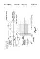
- FIG. 4is a functional block diagram of a linear transmitter 400 using a predistortion system according to one embodiment of the present invention.
- This embodiment of the transmitteris substantially similar to the transmitter described in U.S. Pat. No. 5,732,333 entitled “Linear Transmitter Using Predistortion", which is commonly assigned to the assignee of the present invention and incorporated herein by reference.
- the linear transmitter 400is adapted for use as a paging transmitter in a paging system, although it can be used in any radio frequency (RF) application.
- RFradio frequency
- the transmitter 400in the forward signal processing path, includes a modulator 403, a predistorter 407, a digital quadrature modulator 411, a digital-to-analog converter 412, an analog upconverter 413, the power amplifier 103 and the transmitting antenna 105.
- a feedback loop of the transmitter 400includes a directional coupler 419 (between the power amplifier 103 and the antenna 105), an analog downconverter 423, an analog-to-digital converter 424, a digital quadrature demodulator 425, and a trainer 431.
- the trainer 431is coupled to receive the output signals of the digital modulator 403 and interact with the predistorter 407.
- additional power amplifiersmay be connected in parallel with the power amplifier 103 to increase the gain of the transmitter 400.
- Digital data that is to be broadcast by the transmitter 400is provided to the modulator 403, as represented by an arrow 432.
- the digital datamay be provided by any source.
- the digital data received by the modulator 403is provided from a transmitter controller (not shown) of the paging system.
- the transmitter controllerreceives data over a link channel from a paging terminal and formulates the data for transmission.
- the details of the construction of a transmitter controller, and indeed an entire paging system,can be found in U.S. Pat. No. 5,481,258 to Fawcett et al., U.S. Pat. No. 5,365,569 to Witsaman et al. and U.S. Pat. No. 5,416,808 to Witsaman et al., commonly assigned to the assignee of the present invention and incorporated herein by reference.
- the datais a series of digital symbols, with each symbol representing a predetermined number of bits.
- the number of bits per symbolis dependent upon the particular modulation scheme being transmitted by the transmitter 400.
- Modulation formats in typical conventional paging data systemsinclude, for example, two or four tone frequency shift keying (FSK) modulation, continuous phase FSK (CPFSK), 43K75B8E formal modulation (a type of amplitude modulation developed by Motorola) and quadrature amplitude modulation (QAM).
- QAM formatsinclude, for example, an eight level QAM scheme that would have a three-bit symbol. Similarly, a sixteen level QAM scheme would have four bits per symbol. It will be appreciated that for a three-bit symbol, there are eight possible symbols. Likewise, for a four-bit symbol, there are sixteen possible symbols.
- the modulator 403correlates each particular symbol with predetermined in-phase and quadrature output signals. Thus, for each unique symbol, a different combination of in-phase and quadrature component signals for the base band signal is output by the modulator.
- the modulator 403includes a Texas Instruments TMS320C44 digital signal processor (DSP) microprocessor that is programmed to perform the in-phase and quadrature modulation on the symbols.
- DSPdigital signal processor
- the modulator 403does not "instantaneously" transition from one symbol to another. Such an instantaneous change in in-phase and quadrature output signals would result in high frequency harmonics in the system. Instead, by means of digital filtering, a smooth transition between symbols (and therefore in-phase and quadrature output signals) is achieved.
- One embodiment of this techniquewhich is applicable to an FSK system is disclosed in more detail in U.S. Pat. No. 5,418,818 to Marchetto et al., assigned to the same assignee as the present invention and incorporated herein by reference.
- the predistorter 407is operative to modify the in-phase and quadrature component signals output from the modulator 403 so as to compensate for any distortion that takes place in the power amplifier 103.
- the predistorteruses a predistortion scheme that is dependent not only on the instantaneous power or magnitude envelope of the sample, but also on the power or magnitude envelope of the previous samples. By taking into account the power or magnitude envelope of previous samples, the effect of the trajectory leading to the current sample's power or magnitude envelope is also compensated for in the predistortion of the current sample, improving the linearity of the power amplifier 103. This predistortion scheme is described further below in conjunction with FIGS. 5-13B.
- the output signals of the predistorter 407are then provided to the digital quadrature modulator 411.
- the digital quadrature modulator 411converts the in-phase and quadrature component signals into a single real digital signal.
- the real digital signal from the digital quadrature modulator 411is received by a D-A converter 412 that converts the real digital signal to an analog signal, producing an intermediate frequency output signal.
- the intermediate frequencyis approximately 5.6 MHz in a representative embodiment. Because a single D-A converter is used, the distortion caused by the relative delay and amplitude differences introduced in those conventional systems that use separate D-A for in-phase and quadrature signals is substantially eliminated in the transmitter 400.
- the intermediate frequency output signal from the D-A converter 412is provided to the analog upconverter 413, which converts the intermediate frequency signal to a broadcast frequency signal having a frequency within a frequency band of the paging system.
- the broadcast frequencyis approximately 940 MHz in a representative embodiment.
- the analog upconverter 413can be any suitable conventional upconverter such as, for example, a mixer receiving a local oscillator signal.
- the power amplifier 103receives the broadcast frequency signal from the analog upconverter 413, amplifies the signal, and provides the amplified signal to the transmitting antenna 105 for transmission.
- the power amplifier 103is substantially similar to the power amplifier disclosed in U.S. Pat. No. 5,694,085 entitled "High-Power Amplifier Using Parallel Transistors", assigned to the same assignee as the present invention and incorporated herein by reference.
- any suitable power amplifiercan be used in other embodiments.
- the feedback loopmonitors the amplified signal from the power amplifier 103.
- the coupler 419is a conventional directional coupler positioned relatively close to the antenna 105 and is operative to direct a relatively small portion of the output signal from the power amplifier 103 to the analog downconverter 423.
- the analog downconverter 423operates in an opposite manner to the analog upconverter 413.
- the analog downconverter 423lowers the frequency of the receive signal outputted by power amplifier 103 to an intermediate frequency.
- this intermediate frequencyis substantially the same as the intermediate frequency used in the forward signal processing path.
- Within the analog downconverter 423there is a series of filtering, amplification, and mixing with local oscillator signals processes to generate the intermediate frequency signal, as described in the aforementioned U.S. Pat. No. 5,732,333.
- the intermediate frequency signalis converted from an analog intermediate frequency signal into a digital signal.
- a conventional A-D converter 424such as, for example, an Analog Devices AD9026, which samples the intermediate frequency signal and outputs a digital signal representing the sampled intermediate frequency signal.
- the digital quadrature demodulator 425performs a digital quadrature demodulation of the digital signals and outputs the in-phase component signal and the quadrature component signal.
- the trainer 431receives the output signals of the digital quadrature demodulator 425.
- the trainer 431also periodically receives the output signals from the modulator 403 and the predistorter 407, as described below in conjunction with FIG. 6.
- the trainer 431receives the equivalent of the exact modulated signal that was intended to be sent (the output signals of the modulator 403) and the signal that was actually transmitted (the output signals of the digital quadrature demodulator 425).
- This schemeenables the predistorter 407 to associate the distorted output sample to its corresponding input sample so that the predistorter 407 can more accurately compensate for the distortion caused by the power amplifier 103.
- the trainerprovides one or more "trainer" signals to the predistorter to update the predistorter's response to the in-phase and quadrature signals input to the predistorter as the power amplifier's response changes due to temperature, age, etc.
- the trainermonitors the actual data or voice signals being transmitted to implement the predistortion scheme, as opposed to special sequences (i.e., not normal data or voice signals) as required by some conventional systems.
- special sequencesi.e., not normal data or voice signals
- normal data or voice transmissionsneed not be interrupted to transmit special data sequences to update the predistorter as in these conventional systems.
- the transmitter 400may include digital interpolators 405 and 409, and a digital decimator 429.
- the digital interpolator 405is connected between the modulator 403 and the predistorter 407
- the digital interpolator 409is connected between the predistorter 407 and the digital quadrature modulator 411
- the digital decimator 429is connected between the digital quadrature demodulator 425 and the trainer 431.
- This circuitryprovides further upconversion in the forward signal processing path and corresponding downconversion in the feedback path.
- the transmitter 400includes a synthesizer 435 connected to the analog upconverter 413 and the analog downconverter 423, a phase locked loop (PLL) 437 connected to the digital quadrature modulator 411.
- PLLphase locked loop
- An ovenized reference oscillator 433is connected to both the synthesizer 435 and the PLL 437. This timing circuitry ensures that the modulation, upconversion, downconversion and demodulation are accurately synchronized.
- the output signals of the modulator 403are the in-phase and quadrature component signals sampled at 80,000 samples per second (80 ksps).
- the in-phase and quadrature component signals output by the modulator 403are received by the digital interpolator 405.
- the digital interpolator 405operates to increase the effective sampling rate of the received signals by means of digital interpolation.
- the digital interpolator 405outputs the in-phase and quadrature component signals at a rate of approximately 800 ksps and is implemented with a DSP module having a TMS320C44 DSP microprocessor and associated memory, as described below in conjunction with FIG. 14.
- the signals output by the interpolator 405are received by the predistorter 407.
- the predistorter 407predistorts the received in-phase and quadrature component signals to compensate for the distortion of the power amplifier 103.
- the predistorted 800 ksps component signals from the predistorter 407are received by the digital interpolator 409.
- the digital interpolator 409operates in a fashion similar to the interpolator 405 to increase the effective sampling rate. Specifically, both the in-phase and quadrature component signals are first upconverted in a first step by a factor of two. Thus, after this first conversion, the effective sampling rate of the component signals is approximately 1.6 Msps.
- the signalsare then upconverted by another factor of two, resulting in an effective rate of approximately 3.2 Msps.
- these two 3.2 Msps signalsare passed to a further interpolator which upconverts them by a factor of seven to approximately 22.4 Msps.
- the output signals of the digital interpolator 409are in-phase and quadrature component signals that have been sampled at 22.4 Msps.
- the interpolation stagesinclude digital filtering of the base band signals. The implementation of the digital interpolator 409 is described in more detail in the aforementioned U.S. Pat. No. 5,732,333.
- the digital quadrature modulator 411receives the output signals of the digital interpolator 409 and modulates them as previously described using a digital quadrature modulation scheme.
- the digital quadrature modulator 411uses a digital equivalent of a conventional double balanced modulation scheme in conjunction with a 5.6 MHz carrier signal derived from a 22.4 MHz signal provided by the PLL 437.
- the real digital modulated output signalis then converted to an analog signal by the D-A converter 412.
- the D-A converter 412outputs a 5.6 MHz analog intermediate frequency signal to the analog upconverter 413.
- the analog upconverter 413receives two local oscillator signals provided by the synthesizer 435.
- the two frequencies provided by the synthesizer 435are a 36.9 MHz local oscillator signal and a 897.5 MHz local oscillator signal.
- the analog upconverter 413receives the local oscillator signals for mixing with the 5.6 MHz intermediate frequency signal in a conventional two-stage mixing scheme. In the first stage of the upconversion, the intermediate signal is mixed with the 36.9 MHz local oscillator signal, and the upper side band of the resulting 42.5 MHz signal is amplified and bandpass filtered before being mixed with the 897.5 MHz local oscillator signal.
- the resulting upper side band at 940 MHzis bandpass filtered and provided to the power amplifier 103. It will be appreciated by those skilled in the art of linear RF transmitters that to change the frequency of transmission of the transmitter 400, the local oscillator frequencies generated by the synthesizer 435 can be changed.
- the 940 MHz signalis then amplified by the power amplifier 103 and broadcast through antenna 105 as previously described for transmitter 400.
- the synthesizer 435is a Phillips SA7025 synthesizer chip. As noted above, the synthesizer 435 controls the variable local oscillator signal for precisely determining the transmit frequency of the signal.
- the synthesizer 435uses a reference oscillator 433 that, in a preferred embodiment, is a stable reference at 10 MHz. In this preferred embodiment, this 10 MHz stable reference is obtained from the transmitter controller of a paging base station.
- the 940 MHz receive signal from the coupler 419is provided to the analog downconverter 423, converted to the intermediate frequency of 5.6 MHz, and received by the digital quadrature demodulator 425.
- the digital quadrature demodulator 425operates to generate in-phase and quadrature component signals at 22.4 Msps.
- the digital quadrature demodulatoris implemented using a Xilinx 4003 field programmable gate array (FPGA) that has been configured to perform the digital quadrature demodulation.
- FPGAfield programmable gate array
- the digital decimator 429receives the output signals of the digital quadrature demodulator 425 and performs a decimation by a factor of twenty-eight to produce 800 ksps complex base band signals.
- the downconversionis performed, in a preferred embodiment, by two Harris HSP43220 decimating filter chips programmed to decimate by twenty-eight and to filter the base band signals.
- the 800 ksps complex base band signalsare received by the trainer 431.
- the traineranalyzes the receive signals and the signals from the modulator 403 to control the predistorter 407 to properly compensate for the distortion caused by the power amplifier 103.
- Another important feature of the present inventionis that all of the processing done by each of the components of FIG. 4 is keyed off synchronous clock signals.
- the modulation and demodulationare phase locked to one another with adjustment only needed for the delay through the analog and digital stages, including the power amplifier 103.
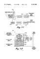
- FIG. 5is a functional block diagram of a predistortion system 500 according to one embodiment of the present invention, with the intervening circuitry omitted for clarity.
- the predistortion system 500includes the predistorter 407, the power amplifier 103 and the trainer 431.
- the predistorter 407 and trainer 431respectively include a memory effect compensator 501 (described further below in conjunction with FIGS. 6-8) and a direct inverse modeller 503 (described further below in conjunction with FIGS. 5A and 5B).
- the predistorter 407receives digital input samples and modifies them with, ideally, the inverse of the transfer characteristic of the power amplifier 103.
- the predistorter 407determines the instantaneous power or magnitude envelope of the current sample, with the predistortion being determined as a function of this instantaneous value.
- the memory effect compensator 501 of the predistorter 407takes into account the power or magnitude envelope of one or more previous samples. More specifically, the inventors of the present invention have observed that modeling the power amplifier transfer characteristic using only the instantaneous power or magnitude does not completely accurately predict the distortion caused by the power amplifier 103.
- the inventors of the present inventionhave observed that the power amplifier's transfer characteristic also depends on past power or magnitude envelopes, which is referred to herein as a "memory effect" of the power amplifier 103.
- the memory effect of the power amplifieris related to the power or magnitude trajectory of the previous power or magnitude envelopes leading to the instantaneous power or magnitude envelope of the current sample. This memory effect is believed to be a heretofore unappreciated factor in the distortion caused by the power amplifier.
- the trainer 431receives the power amplifier output signals after appropriate downconversion and analog-to-digital conversion and determines the inverse of the power amplifier transfer characteristic.
- the trainer 431also receives the digital sample of the modulation signal. Because the timing and sampling is synchronized, the trainer 431 matches (by taking into account the delay through the intervening circuitry) the input digital sample with the corresponding sample of the power amplifier output signal.
- the trainer 431models the inverse of the power amplifier transfer characteristic on a sample-by-sample basis.
- the trainer 431then "qualifies" this "inverse” data so that the trainer only trains on valid data. This qualifying process is described below in conjunction with FIGS. 13-13B.
- the trainer 431updates the predistorter 407 with qualifying inverses of the power amplifier transfer characteristic.
- the trainer 431includes the direct inverse modeller 503.
- the block diagrams of FIGS. 5A and 5Billustrate the concept of direct inverse modeling.
- the inverse of the power amplifier transfer characteristicis modeled as a non-linear "filter" with the input and output leads interchanged. That is, the output signal of the power amplifier is considered the input to the non-linear "filter", whereas the input signal of the power amplifier is considered the output of the non-linear "filter”, as shown in FIG. 5A.
- the complex "gain” as determined from the output lead of the power amplifier to the input lead of the power amplifierrepresents the "inverse" characteristic that the predistorter should multiply with the complex modulation signal sample before amplification by the power amplifier.
- the trainerinstead of building a forward model of the power amplifier transfer characteristic (e.g. FIG. 5A) and then mathematically calculating the inverse, the trainer updates the predistorter with the "output sample-to-input sample" gain and phase of the power amplifier, indexed by the instantaneous power or magnitude of the modulation signal sample.
- the computationally intensive mathematical inversion processis avoided, enabling the trainer to calculate the inverse characteristic of the power amplifier at a relatively high sample rate in real time.
- the trainer 431indexes the inverse characteristic using the modulation signal samples.
- the modulation signal samplesare typically much less noisy than the power amplifier output samples, resulting in a more accurate predistortion by the predistorter 407.
- FIG. 6is a more detailed functional block diagram of the predistortion system 500 depicted in FIG. 5.
- the predistorter 407 of this embodimentis implemented with a predistortion filter 601 and a LUT 603.
- the predistortion filter 601is implemented using a digital filter circuit (see FIG. 7), with the filter coefficients or taps of the digital filter circuit being stored in the LUT 603.
- the predistortion filter 601provides the predistortion functionality as a function of both the instantaneous power or magnitude envelope of the current modulation signal sample and the power or magnitude envelopes of previous modulation signal samples.
- the trainer subsystem 605(i.e., the trainer and circuitry for sampling, downconverting and digitizing the power amplifier output signal) periodically updates the inverse characteristics of the power amplifier 103 by providing a write address and updated filter coefficients to the LUT 603, as shown by the lines 607.
- the trainer subsystem 605periodically receives "batches" of data containing the modulation signal samples, power amplifier input signal samples and power amplifier output signal samples as indicated by the lines 609, 611 and 613, respectively.
- the trainer subsystem 605provides the inverse characteristics of the power amplifier to the LUT 603 as described below in conjunction with FIGS. 12-13B.
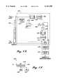
- FIG. 7is a functional block diagram of the predistortion filter 601 according to one embodiment of the present invention.
- the predistortion filter 601includes a complex gain (or static) branch 701, and a parallel weighted branch 703 that implements the functionality of the memory effect compensator 501 (FIG. 5).
- the output signals of these branchesare then summed to produce the filter output signal.
- This filter output signalis the predistorted signal serving as a basis (i.e., before upconversion and D/A conversion) for the input signal received by the power amplifier (see FIG. 4). Because the filter output signal is digital, the filter output signals are also referred to herein as the filter output samples.
- the predistortion filter 601is implemented with a TMS320C44 DSP microprocessor and associated memory (not shown) using techniques well known in the art of digital linear transmitters.
- the predistortion filter 601also includes an address generator 707 that is used to generate the read addresses to access the LUT 603.
- the address generator707is described below in conjunction with FIG. 11.
- the static branch 701multiplies the modulation signal sample by a complex parameter from the LUT 603.
- the address generator 707uses the instantaneous power or magnitude envelope of the current modulation signal sample to generate the address of this complex parameter.
- the complex parameterrepresents part of the "inverse" characteristic to be multiplied with the current modulation signal sample.
- the weighted branch 703includes an envelope filter 705, which generates weighted values as a function of previous power or magnitude envelope samples.
- the envelope filter 705is described further below in conjunction with FIGS. 9 and 10.
- the envelope filter 705generates the weighted values as a function of the current and the previous modulation signal sample, using a first order digital filter to model the memory effects of the power amplifier.
- the scalar weighted valuesare then multiplied by the complex input samples.
- the resulting signalis multiplied by the complex parameters stored in the LUT 603.
- the LUT 603is indexed by the instantaneous power or magnitude of the modulation samples to provide the appropriate complex parameter for the weighted branch 703, which is calculated by the address generator 707.
- the LUT 603may include additional dimensions or tables that are indexed by other pertinent parameters. For example, LUT tables may be addressed by both instantaneous power or magnitude and also by an average of envelope power or magnitude of previous samples. In addition, different tables may be used for different modulation schemes or during ramp up or ramp down of power to the power amplifier. Of course, adding additional tables tends to increase the memory requirements, processing time and power dissipation of the predistortion system. However, increased DSP microprocessor and memory device performance may make these systems easier to implement in the future.
- FIG. 8is a functional block diagram of a predistortion filter 800 having additional indexes compared to the predistortion filter 601 (FIG. 7), according to another embodiment of the present invention.
- the predistortion filter 800has multiple envelope filters 802 1 -802 N , an address generator 803 and a LUT 804.
- the LUT 804has a column associated with each envelope filter, which are indexed by the address generator 803 as a function of the instantaneous power or magnitude envelope of the current modulation signal sample and power or magnitude envelopes of past modulation signal samples.
- the address generator 803is described further below in conjunction with FIG. 11.
- optional LUTs 806 1 -806 Mcan be included to implement a multi-table predistortion filter as described above in conjunction with FIG. 7.
- the predistortion filter 800operates in a substantially similar manner as the predistortion filter 601 (FIG. 7), with the additional envelope filters providing additional weighted branches to account for other memory effects.
- the envelope filters 802 1 -802 Nmay correspond to actual past power or magnitude envelope samples rather than the average of past power or magnitude envelope samples as in the predistortion filter 601 (FIG. 7).
- the envelope filtersmay also correspond to different filtered averages of past sample power or magnitude.
- FIG. 9is a functional block diagram of an envelope filter 900 implemented with a finite impulse response (FIR) digital filter, according to one embodiment of the present invention.
- the envelope filter 900includes a sample power calculator 902, a delay circuit 904 and an adder 906.
- the delay circuit 904 and adder 906form a FIR digital filter.
- the sample power calculator 902provides a signal representing the power of the current modulation signal sample to the delay circuit 904 and the adder 906.
- the delay circuit 906then provides the power of the previous modulation signal sample to the adder 906, which subtracts this previous modulation sample power from the current modulation signal power to generate the output signal of the envelope filter.
- the sample power calculator 902 and the FIR filterare implemented by the TMS320C44 DSP microprocessor and associated memory (not shown) using techniques well known in the art of digital linear transmitters.
- FIG. 9Aillustrates an envelope filter 910 similar to that in FIG. 9 but in which the sample power calculator is replaced by a sample magnitude calculator 912.
- FIG. 10is a functional block diagram of an envelope filter 1000 implemented with an infinite impulse response (IIR) digital filter, according to another embodiment of the present invention.
- the envelope filter 1000includes the sample power calculator 902, the delay circuit 904, the adder 906, a second delay circuit 1002 and a gain block 1004.
- the delay circuit 904, adder 906, delay circuit 1002 and gain block 1004form an IIR digital filter.
- the sample power calculator 902provides a signal representing the power of the current modulation signal sample to the delay circuit 904 and the adder 906.
- the delay circuit 904then provides the power of the previous modulation signal sample to the adder 906.
- the adder 906also receives a scaled version of the previous output sample of the envelope filter from the delay circuit 1002 and the gain block 1004.
- the gain block 1004scales each output sample before the output sample is stored in the delay circuit 1002.
- the adder 906then subtracts this previous modulation sample power from the sum of the current modulation signal power and the previous envelope filter output sample to generate the output signal of the envelope filter.
- the sample power calculator 902 and the IIR filterare implemented by the TMS320C44 DSP microprocessor and associated memory (not shown) using techniques well known in the art of digital linear transmitters.
- FIGURE 10Aillustrates an envelope filter block 1010 similar to that in FIG. 10 but in which the sample power calculator is replaced by a sample magnitude calculator 1012.
- FIG. 11is a functional block diagram of the address generator 707 of the predistortion filter 601 (FIG. 7), according to one embodiment of the present invention.
- the address generator 707has a sample power calculator 1101, multipliers 1103 and 1109, quantizers 1105 and 1111, and an averager 1107.
- the sample power calculator 1101receives the current modulation signal sample and outputs a signal representing the magnitude of the instantaneous power envelope of the current modulation signal sample.
- a sample magnitude calculatormay be used instead of the sample power calculator 1101 in other embodiments in which the predistortion scheme is based on the magnitude of the modulation signal instead of power.
- the aforementioned TMS320C44 DSP microprocessor (not shown) implementing the predistortion filter 601is programmed to calculate the power or magnitude from the digital modulation signal samples.
- the instantaneous power or magnitude sample from the sample power (or magnitude) calculator 1101is received by the multiplier 1103, which then scales the instantaneous power or magnitude sample by a constant in order to match the range of table memory addresses.
- the scaled instantaneous power or magnitude sampleis then quantized by the quantizer 1105. This quantized value serves as the table address for the LUT 603 (FIG. 7), which stores the values describing the complex inverse characteristic for the branches of the predistortion filter.
- the averager 1107calculates the mean of the instantaneous power or magnitude samples of the current and one or more previous power or magnitude samples.
- This simple schemeprovides a relatively good indication of the trajectory of the instantaneous power or magnitude envelope of the current power or magnitude sample without requiring a relatively large amount of processing time, memory and hardware.
- the averagemay be calculated using different schemes. For example, the average may be calculated from a different number of previous power or magnitude samples, or by using a weighted averaging scheme that gives less weight for the oldest power or magnitude samples.
- the multiplier 1109 and quantizer 1111provide the table address for the selection of alternative tables 806 1 -806 M (FIG. 8) as described above for the multiplier 1103 and quantizer 1105.
- the address generatorcan also receive control signals from the transmitter controller (not shown) indicative of the current modulation format (e.g., FSK, QAM, etc.) and whether the transmitter is ramping up or down in power at the start or finish of a transmission.
- the transmitter controllerprovides the modulation signal samples to the modulator 403.
- the address generatorselects the LUT corresponding to the current combination of modulation format and state of the transmitter.
- FIG. 12is a functional block diagram of the trainer 431 (FIG. 5), which includes a solver 1201, an interpolator/extrapolator 1202, and an averager 1204, according to one embodiment of the present invention.
- the solver 1201includes the functionalities of a data validator 1203 and the direct inverse modeler 503.
- the direct inverse modeler 503comprises the model builder 1205, the parameter estimator 1206 and the coordinate mapper 1207.
- the trainer 431, including the solver 1201is implemented with a TMS320C44 DSP microprocessor and associated memory.
- the trainer 431receives and stores the modulation signal samples from the transmitter controller (not shown).
- the trainer 431also receives and stores from the digital decimator 429 (FIG. 4) complex digital signals that are scaled down, downconverted and digitized samples of the power amplifier output signals. These signals are referred to herein as the PA out samples.
- the trainerreceives and stores complex digital signal samples corresponding to the power amplifier input signals.
- the trainer 431generates these power amplifier input signals by duplicating the predistorter functionality to generate the same input signals (prior to interpolation, upconversion and D/A conversion) that were received by the power amplifier. These signals are referred to herein as the PA in samples.
- This embodimentis advantageously used to reduce the interconnection required to the trainer 431.
- the trainer 431may have an input port coupled to the output port of the predistorter to receive the PA in samples directly from the predistorter. The trainer 431 then provides the proper delays and synchronization to match the PA in samples and PA out samples with the originating modulation signal samples.
- the solver 1201then periodically processes a "batch" or "block” of this stored data to generate the complex parameters used to update the LUT of the predistorter.
- the traineruses the instantaneous power or magnitude of the modulation signal samples to generate the write addresses of the predistorter LUT at which the trainer stores the complex inverse characteristics obtained by the direct inverse modeller 503 (i.e., indexing the LUT using the modulation signal samples).
- the write addressesare obtained in the same way as the read addresses as described with respect to FIG. 11.
- the solver 1201it first performs interpolation to increase the number and time resolution of the samples used in the training. In one embodiment, this interpolation is used to achieve, in effect, a 48 megasamples/second sampling rate. This interpolation has been found to improve the linearization of the transmitter output signals.
- the trainer 431then quantizes the samples into "bins" that are equal in number to the number of table addresses in the predistorter LUT.
- the data validator 1203checks that there are enough data samples in a bin and that their distribution is statistically significant (i.e., not too much variation). If the values associated with a bin are qualified by the data validator 1203, then the PA out samples are processed by the direct inverse modeler as described below, otherwise the bin is left empty.
- the model builder 1205transforms the PA out samples to generate training signals (which are vectors) that are orthogonal to each other. These training signals are also referred to as "predictor variables.”
- the parameter estimator 1206uses these orthogonal signals together with the PA in samples to derive new complex parameter values for the bin.
- a least squares methodis employed by the parameter estimator 1206 to compute complex parameters for each bin.
- the coordinate mapper 1207maps the complex parameters calculated by the parameter estimator 1206 into the signal coordinate system used in the predistortion filter 601. The values computed by the coordinate mapper can then be used to update the predistorter LUT.
- each calculated parametercan be averaged or filtered with the corresponding previously trained parameters (or, alternatively, a weighted average of previously trained parameters) to generate the updated parameter. This averaging is used to smooth out changes in the parameter and to get a better parameter estimate. This value can then be used to update the predistorter LUT.
- the interpolator/extrapolator 1202determines the parameters of the empty bins (if any) by interpolation or extrapolation from the other surrounding bins. Then the averager 1204 averages each calculated parameter with the corresponding parameter currently stored in the predistorter LUT. When averaging a calculated parameter with the corresponding current parameter in the predistorter LUT, the trainer reads the contents of the predistorter LUT into the trainer. Similarly, when averaging a calculated parameter with a weighted average of past parameters, the trainer may include a memory array storing the running weighted average. These averaged values are then used to update the predistorter LUT.
- the solver 1201, validator 1203, interpolation/extrapolation 1202 and averaging 1204 functionsare implemented in the TMS320C44 DSP microprocessor and associated memory (not shown) using techniques well known in the art of digital linear transmitters.
- the operation of the trainer 431is described further below in conjunction with FIGS. 13 and 13A.
- parameters stored in the predistorter's LUTwill have a pair of complex values for each address, one for each column of the LUT (e.g., see LUT 603 in FIG. 7).
- One of these valuescorresponds to the complex parameter to be multiplied with the complex gain (static) branch of the modulation signal sample, and the other value corresponds to the complex parameter to be multiplied with the weighted branch of the modulation signal sample.
- FIG. 12Ais a functional block diagram of the trainer 431 (FIG. 5), according to another embodiment of the present invention.
- This embodimentis substantially similar to the embodiment of FIG. 12, except for the inclusion of the validator 1208.
- This embodimentcan be advantageously used to qualify the parameter estimates computed by the coordinate mapper 1207.
- the validator 1208checks each parameter value to determine whether it is reliable. For instance, the validator 1208 could check the magnitude of the complex parameters for each bin comparing it to a predetermined threshold. If the magnitude of a complex parameter does not exceed the threshold, the parameter is considered reliable. Only reliable parameters are used for processing in the interpolator/extrapolator 1202 and the averager 1204.
- FIG. 12Bis a functional block diagram of yet another embodiment of the trainer 431. This embodiment is substantially similar to the embodiment of FIG. 12 except that the averager 1204 is connected between the solver 1201 and the interpolator/extrapolator 1202. Thus, the calculated parameters are averaged with the stored parameters before the interpolation/extrapolation process.
- FIG. 13is a functional block diagram of the solver 1201 (FIG. 12).
- the solver 1201includes the data validator 1203, the parameter estimator 1206, the coordinate mapper 1207 and the model builder 1205.
- the model builder 1205includes the envelope filter 1301, multipliers 1302, 1303 and 1304, adder 1308, norm calculators 1305 and 1309, dividers 1306 and 1310, the conjugate transposer 1307 and the data buffer 1311. These functions are implemented in the TMS320C44 DSP microprocessor and associated memory of the trainer 431 (FIG. 7).
- the solver 1201receives the PA in and PA out samples formatted as column vectors, and the addresses corresponding to these samples in the predistorters LUT derived by the modulation signal samples.
- the PA in and PA out samplesare qualified by the data validator 1203 which allows further processing of these signals in the solver 1201 only if the and PA in and PA out samples are reliable.
- the envelope filter 1301filters the PA in samples and provides an output signal as a function of previous PA out samples to the multiplier 1302.
- the envelope filter 1301is implemented in the same manner as the envelope filter 900 (FIG. 9 or other versions depicted in FIGS. 9A, 10 or 10A) of the predistorter. Consequently, the memory effects of the PA out samples are determined in the same manner as in the predistorter.
- the PA out samplesare scaled in the divider 1306.
- Divider 1306divides the imaginary and real components of the PA out samples by the Euclidean norm of the PA out vector.
- the Euclidean norm of the PA out vectoris computed in the norm calculator 1305.
- the resulting training signal ⁇ 1is input into the data buffer 1311 and the multipliers 1303 and 1304.
- the multiplier 1302multiplies the envelope filter output signal with the PA out samples.
- the signal at the output of multiplier 1302is provided to the transposer 1307 and the adder 1308.
- the transposer 1307computes the conjugate transpose of the output of multiplier 1302 to produce a row vector.
- the multiplier 1303multiplies this row vector with a column vector at the output of divider 1306, which results in the complex value g. This constant is then used in the multiplier 1304 to scale ⁇ 1 .
- the signal at the output of multiplier 1304is subtracted from the output of multiplier 1302 in the adder 1308.
- the resulting column vector v 2is normalized by the norm calculator 1309 and divider 1310 to produce a second training signal ⁇ 2 .
- the training signals ⁇ 1 and ⁇ 2are orthogonal to each other.
- This training techniquecan be used to improve the inverse PA transfer characteristic that is computed in the solver 1201.
- this procedureenables the trainer 431 to gather more precise and useful information out of the PA out signal. Consequently, the LUT is better trained and predistortion performance is significantly improved as compared to the method described in prior U.S. Pat. No. 5,923,732 entitled "Method and Apparatus for Linear Transmission by Direct Inverse Modeling.”
- the orthogonal training signals ⁇ 1 and ⁇ 2 together with the PA in samples and the corresponding predistorted LUT addressare stored in the data buffer 1311.
- the parameter estimator 1206then accesses the data in the data buffer 1311 to calculate the values of the complex parameters for the bin.
- These complex parametersare processed by the coordinate mapper 1207 which maps them into the signal coordinate system used in the predistortion filter 601.
- the parameter values computed by the coordinate mapper 1207are then used as a basis for updating the predistorter LUT.
- the parametersare processed by the averager 1202 and the interpolator/extrapolator 1204 (FIGS. 12 and 12B) to generate the values for updating the predistorter LUT, as described further below in conjunction with FIG. 13A.
- additional envelope filters, multipliers, dividers, adders and norm calculatorsmay be included in the solver 1201 to implement other memory effect modeling algorithms.
- Each additional envelope filteradds an extra orthogonal training signal ⁇ 1 .
- the solver 1201would use similar algorithms as for the two-level memory effect model to process this increased amount of data with, of course, an increase in the processing time for each block of data.
- FIG. 13Ais a flow diagram illustrating the process of determining complex parameters for updating the predistorter LUT, according to one embodiment of the present invention.
- the solver 1201calculates complex "inverse" parameters corresponding to the predistorter LUT addresses, as indicated by a block 1323 in the flow chart of FIG. 13A.
- the solver 1201receives a block of synchronized modulation signal samples, PA in samples, PA out samples and LUT addresses. As described above in conjunction with FIG. 12, these samples are quantized into bins corresponding to LUT addresses. The samples may also be interpolated to increase their numbers as described in conjunction with FIG. 12.
- the solver 1201calculates complex parameters for each bin by computing the orthogonal training signals ⁇ 1 and ⁇ 2 at step 1322 and using them to solve for the parameter estimates. A least squares technique is used for computing the parameter estimates. More specifically, for each bin, the solver 1201 solves the regression equation:
- PA inkdenotes the set of PA in samples for bin k
- CG k and CG2 kare complex coefficients for bin k
- ⁇ 1k and ⁇ 2kare orthogonal training signals for bin k computed as described above in conjunction with FIG. 13.
- the prime (') indicatordenotes the conjugate transpose operator.
- the coordinate mapper 1207transforms CG k and CG2 k to generate values suitable for updating the predistorter LUT. This coordinate transformation is accomplished according to the following equations below: ##EQU1##
- a next step 1326is performed in which the averager 1202 finds a weighted average of these new parameters and the current parameters. Typically, the averaging is done so that the more weight is given to the most recent parameters. These weighted averages are then used to update the predistorter LUT at step 1327.
- FIG. 13Bis a flow diagram illustrating the process of determining complex parameters for updating the predistorter LUT, according to another embodiment of the present invention. This embodiment is substantially similar to the embodiment described in conjunction with FIG. 13A except that the extra validation process is performed after the calculation of the parameters.
- a threshold valueis set in the validator 1208. If the magnitude of the computer parameters exceeds the threshold, the coefficients for the bin are considered unreliable and the bin is emptied.
- the filtering step 1326may be performed before the step 1325. That is, the calculated parameter values may be averaged with the corresponding current (or, alternatively, a running weighted average of past) predistorter LUT parameters before empty bins are interpolated or extrapolated. Accordingly, averaging only takes place with calculated parameters that have passed the validation process.
- FIG. 14is a block diagram of a DSP module 1400 for implementing a predistorter and trainer, according to one embodiment of the present invention.
- the DSP module 1400is substantially similar to the DSP module disclosed in the aforementioned U.S. Pat. No. 5,732,333, but a brief description is included herein for completeness.
- the DSP module 1400includes a microprocessor 1401, a static random access memory (SRAM) 1403 and a nonvolatile memory (NVM) 1405.
- the microprocessor 1401is a DSP microprocessor TMS320C44 available from Texas Instruments, although any suitable microprocessor can be used.
- the microprocessor 1401is connected to the SRAM 1403 and the NVM 1405.
- the NVM 1405is implemented using a flash electrically programmable read only memory (EPROM).
- EPROMelectrically programmable read only memory
- the DSP module 1400can be configured or programmed for a variety of functions, such as, for example, forming part of a modulator, interpolator, trainer or predistorter. Further, the DSP module 1400 can be reprogrammed to change its functionality by replacing the configuration program stored in the nonvolatile memory 1405.
- the predistorterwhen implementing the predistorter with a DSP module 400, can, on powerdown, store the predistortion values in the nonvolatile memory 405. As a result, the predistorter can use these stored values immediately after power up to predistort data to be transmitted. Thus, the predistorter does not require a special initialization process with special training sequences as required in many conventional systems.
- the DSP module in the modulator 403can be programmed to scale the in-phase and quadrature output signals at start-up and powerdown to "ramp" the input signals to the power amplifier using a look up table (LUT) containing a smooth ramping function of multiplier factors, thereby reducing transients in the power supply voltages and spurious output signal from the power amplifier.
- LUTlook up table
- a Gaussian scalingis used. Smooth ramping can be individually applied to individual subcarriers when more than one is transmitted simultaneously.
- intermodulation products and other distortionlocated in the desired broadcast RF channel (referred to as “in-band”) adversely affects the training of the predistorter.
- the in-band distortionis not only generated by the non-linearity of the power amplifier, but also from other low frequency sources that are not necessarily from the power amplifier. Sources of these non-power amplifier distortions may include any combination of dynamic power supply effects including ripple and transient noise.
- bias irregularities on the power amplifier transistors and thermal transientscan introduce low frequency (in-band) effects that are not a reproducible part of the distortion and which is not helpful to model and predistort.
- the present inventionsolves this problem by removing the in-band distortion from the power amplifier output signal that is used by the trainer.
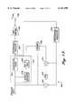
- the transmitter 1000includes a power amplifier 1002, a downconverter/demodulator 1004, an upconverter/modulator 1006, a trainer 1008, a predistorter 1010, a low-pass filter (LPF) 1012, first summer 1016 and second summer 1014, broadcast antenna 1024, and directional coupler 1026.
- a power amplifier 1002a downconverter/demodulator 1004
- an upconverter/modulator 1006a trainer 1008, a predistorter 1010, a low-pass filter (LPF) 1012, first summer 1016 and second summer 1014, broadcast antenna 1024, and directional coupler 1026.
- LPFlow-pass filter
- the modulated inputis provided to the predistorter 1010.
- the predistorteris preferably comprised of an address generator 1018, a look up table 1020, and a non-linear predistortion filter 1022. These elements of the predistorter 1010 are detailed above.
- the modulated inputis a digital complex baseband signal including in-phase (I) and quadrature (Q) components.
- the predistorter 1010is operative to filter the modulated input so as to "predistort" the modulated input.
- the output of the predistorter 1010is provided to the upconverter/modulator 1006.
- the function of the upconverter/modulator 1006is twofold.
- the upconverter/modulator 1006acts to combine the in-phase (I) and quadrature (Q) components of the predistorter output.
- the upconverter/modulator 1006acts to increase the frequency of the signal to the desired broadcast RF channel.
- the upconverter 1006also includes a digital to analog converter for converting the digital signal output by predistorter 1010 into an analog signal for transmission. The output of the upconverter 1006 is then provided to power amplifier 1002 for amplification and broadcast by broadcast antenna 1024.
- Directional coupler 1026monitors the output of the power amplifier 1002 by monitoring the signal transmitted by broadcast antenna 1024.
- the output of the power amplifier 1002is then input into downconverter/demodulator 1004.
- the downconverter/demodulator 1004performs exactly the opposite function as the upconverter/modulator 1006. Namely, the downconverter/demodulator 1004 acts to first decrease the frequency of the received signal from the desired broadcast RF channel. It is important that upconverter/modulator 1006 and downconverter/demodulator 1004 be precisely matched to each other in terms of frequency conversion. In other words, the frequency of the output of the downconverter/demodulator 1004 should be substantially the same as the frequency of the input of the upconverter/modulator 1006.
- the downconverter/demodulator 1004also includes an analog to digital converter for converting the analog received signal into a digital signal. Finally, the downconverter/demodulator 1004 acts to demodulate the digital signal into a digital complex baseband signal having in-phase (I) and quadrature (Q) components.
- the output of the downconverter/demodulator 1004is then provided as an input to the first summer 1016 and the second summer 1014. Another input of the first summer 1016 is the modulated input.
- First summer 1016is operative to subtract the output of downconverter/demodulator 1004 from the modulated input to form an error signal. Because the output of the downconverter/demodulator 1004 (derived from the output of the power amplifier 1002) is subtracted from the modulated input, the error signal is the negative of the distortion caused by the power amplifier 1002.
- LPF 1012has a cutoff frequency of 24 kHz. However, it can be appreciated by those skilled in the art that the cutoff frequency may be adjusted depending upon the bandwidth of the desired broadcast RF channel.
- the function of LPF 1012is to remove that part of the error signal that is outside of the desired broadcast RF channel (referred to as "out-of-band").
- the output of LPF 1012is referred to as the in-band error signal.
- the in-band error signalis the negative of the in-band distortion caused by power amplifier 1002.
- the in-band error signalis added to the output of the downconverter/demodulator 1004 at second summer 1014. This has the effect of subtracting the in-band distortion from the output of the downconverter/demodulator 1004.
- the output of the second summer 1014is referred to as the modified power amplifier output signal.
- the modified power amplifier output signalis then used by the trainer 1008 (as discussed above) to calculate the values stored in look up table 1020 of predistorter 1010. Thus, the modified power amplifier output replaces the power amplifier output shown in FIG. 6.
- the modulated inputis provided directly as an input to trainer 1008.
- the trainerhas a third input that is the input signal to the power amplifier 1002.
- the trainer 1008has three inputs: the modified power amplifier output signal, the modulated input, and the input to the power amplifier. Each of these three inputs are acted upon by the trainer 1008 in accordance with the description above to generate numeric values that provided to look up table 1020 for use by the predistorter 1010.
Landscapes
- Engineering & Computer Science (AREA)
- Power Engineering (AREA)
- Physics & Mathematics (AREA)
- Nonlinear Science (AREA)
- Computer Networks & Wireless Communication (AREA)
- Signal Processing (AREA)
- Amplifiers (AREA)
- Transmitters (AREA)
Abstract
Description
This is a continuation-in-part of 08/850,940 U.S. Pat. No. 5,923,712 entitled "Method and Apparatus for Linear Transmission by Direct Inverse Modeling," to Leyendecker et al., filed on May 5, 1997, assigned to the same assignee herein, and expressly incorporated in its entirety by reference herein, and further, this application is related to U.S. Pat. No. 5,867,065 entitled "Frequency Selective Predistortion in a Linear Transmitter" to Leyendecker et al., filed on May 7, 1997, assigned to the same assignee herein, and expressly incorporated in its entirety by reference herein.
The present invention relates to linear transmitters and, more particularly, to linear transmitters using predistortion.
It is well-known that the power amplification stages of typical radio frequency (RF) broadcast transmitters behave in a nonlinear fashion when operated near peak capacity. One simple solution to this problem is to "back off" the power amplifier and only operate the power amplifier below saturation in its linear region. However, backing off the power amplifier tends to reduce the power conversion efficiency of the power amplifier. Additionally, for a given required transmitter output power, the power amplifier used must be larger (and more expensive) than a power amplifier that can be operated at peak capacity.
Furthermore, although backing off would allow the power output of the power amplifier to behave more linearly, backing off would not alleviate the phase distortion of the power amplifier. For modulation schemes that only depend upon modulation of amplitude (such as AM), phase distortion is of relatively little concern. However, for other types of modulation schemes that rely upon both amplitude and phase modulation, phase distortion is an important concern.
An alternative solution, commonly referred to as predistortion, compensates for the distortion caused by the power amplifier by "predistorting" the signal to be amplified with the "inverse" of the transfer characteristic of the power amplifier. FIG. 1 is a simplified block diagram of an exemplary conventional predistortion subsystem 100 for use in a transmitter. Apredistorter 101 is coupled to receive a modulation signal to be amplified by apower amplifier 103 and broadcast through anantenna 105. Thepredistorter 101 operates on the received modulation signal to predistort the modulation signal with the calculated inverse of the transfer characteristic of thepower amplifier 103. Thus, ideally, the "predistortion" and the power amplifier distortion cancel each other out to achieve a linear amplification of the output signal. In this example, the predistortion subsystem 100 includes a trainer 107 to monitor the power amplifier input and output signals to determine the distortion caused by thepower amplifier 103, which may change over time. The trainer 107 then provides signals to update thepredistorter 101 so thatpredistorter 101 tracks any changes in the transfer characteristic of thepower amplifier 103.
FIG. 2 is a simplified block diagram of the conventional predistorter 101 (FIG. 1). Typical conventional predistortion schemes attempt to model the performance of the power amplifier and calculate the "inverse" of the amplifier transfer characteristic. All of the predistortion schemes known to the inventors of the present invention attempt to model the power amplifier performance as a function of the instantaneous power or magnitude envelope of the input signal to the power amplifier. Accordingly, these conventional predistortion schemes predistort the input signal as a function of the power or magnitude of the signal to be amplified. For example, U.S. Pat. No. 4,291,277 issued to Davis et al. and U.S. Pat. No. 5,049,832 issued to Cavers disclose such a scheme. Thus, in this scheme, thepredistorter 101 includes apower calculator 201 for calculating the instantaneous power or magnitude of the received modulation signal. The calculated instantaneous power or magnitude is then used to access a look-up table (LUT) 203 that stores a corresponding complex value for this particular instantaneous power or magnitude. This complex value approximates the local inverse of the transfer characteristic of the power amplifier for this particular instantaneous power or magnitude of the modulation signal. TheLUT 203 can be periodically updated by the trainer 107 (FIG. 1) so that the complex values reflect any changes in the transfer characteristic of the power amplifier 103 (FIG. 1). TheLUT 203 provides this complex value to amultiplier 205, which multiplies the modulation signal with this complex value to predistort the modulation signal. Thus, when the predistorted modulation signal is subsequently amplified by the power amplifier, the predistortion cancels to some extent the distortion caused by the power amplifier.
Although these conventional predistortion schemes represent an improvement over earlier schemes to reduce power amplifier distortion, the inventors of the present invention have observed that modeling the power amplifier transfer characteristic using only the instantaneous power or magnitude does not completely accurately predict the distortion caused by the power amplifier. Consequently, predistortion schemes based on such models cannot completely correct the distortion caused by the power amplifier.
FIG. 3 is a flow chart illustrative of a conventional process of calculating the complex values that are stored in the LUT 203 (FIG. 2). In astep 301, the trainer 107 (FIG. 1) determines the instantaneous magnitude and phase of the input signal to the power amplifier 103 (FIG. 1) and the instantaneous magnitude and phase of the amplified (and distorted) output signal. The trainer 107 typically stores these values in a LUT (not shown) within the trainer and, thus, can directly model the transfer characteristics of thepower amplifier 103. Instep 302, these characteristics are stored in a first lookup table (LUT). This first trainer LUT is indexed using the actual amplifier output power or magnitude. Then in anext step 303, the trainer 107 calculates the mathematical "inverse" of the transfer characteristic of the power amplifier. This step is generally computationally intensive, thereby undesirably increasing the complexity of the hardware and software of the trainer 107 and consuming processing time and power. In addition, because the trainer LUT is indexed by actual amplifier output power or magnitude, addressing errors may occur because the amplifier output signal is potentially noisy. Then in astep 305, the trainer stores the calculated inverse in thesecond LUT 203 of thepredistorter 101.
In view of the above shortcomings of conventional predistortion schemes, there is a need for a predistortion system that will compensate for power amplifier distortion more accurately than the conventional predistortion systems that are based on instantaneous envelope power or magnitude. There is also a need for a less complex and more accurate scheme to provide the inverse of the power amplifier transfer characteristic.
In accordance with the present invention, a system for linearly transmitting an amplified output signal using predistortion is provided. In one embodiment adapted for use with digital input data, the system uses a straight inverse modeling scheme to more easily and accurately determine the inverse of the distortion caused by a power amplifier of a RF transmitter. In this embodiment, the "inverse" of the power amplifier is directly modeled by considering the power amplifier as a signal processing block with the input and output ports reversed. More specifically, the output signal of the power amplifier is considered the input signal of the "inverse" power amplifier model and, correspondingly, the modulated input signal of the power amplifier is considered the output signal of the "inverse" power amplifier model. As a result, the computationally intensive inversion required by the conventional schemes is avoided, which serves to free up resources and reduce processing time and power consumption. Further, unlike the conventional inverse modeling schemes, the direct inverse modeling scheme of the present invention indexes the LUT using the modulated input signals instead of the potentially noisier output signals, which helps to increase the accuracy of the predistortion. In addition, in one embodiment, the predistorter system stores complex coefficients in the LUT, which are then used as the tap weights of a digital filter implementing the predistorter.
In accordance with other aspects of the present invention, the direct inverse modeling scheme of this invention uses orthogonal signals for training. This has been found to significantly improve predistortion performance as compared to the direct, inverse modeling method described in U.S. Pat. No. 5,923,732 entitled "Method and Apparatus for Linear Transmission by Direct Inverse Modeling."
In accordance with still other aspects of the present invention, the trainer uses a modified version of the power amplifier output signal. The modified power amplifier output signal has the in-band distortion removed from the power amplifier output signal. As a result of this pre-conditioning of the power amplifier output signal, significant reductions in the nonlinear distortion of the power amplifier can be achieved.
The foregoing aspects and many of the attendant advantages of this invention will become more readily appreciated as the same becomes better understood by reference to the following detailed description, when taken in conjunction with the accompanying drawings, wherein:
FIG. 1 is a block diagram of a conventional predistortion system;
FIG. 2 is a block diagram of a conventional predistorter as depicted in FIG. 1;
FIG. 3 is a flow diagram of a conventional process to calculate the complex values of the predistorter depicted in FIG. 2;
FIG. 4 is a block diagram of a transmitter using a predistortion system according to one embodiment of the present invention;
FIG. 5 is a block diagram of a predistortion system according to one embodiment of the present invention;
FIG. 5A and FIG. 5B are block diagrams illustrating direct inverse modeling according to one embodiment of the present invention;
FIG. 6 is a more detailed block diagram of the predistortion system depicted in FIG. 5;
FIG. 7 is a block diagram of a predistortion filter according to one embodiment of the present invention;
FIG. 8 is block diagram of a predistortion filter according to a second embodiment of the present invention;
FIG. 9 is a block diagram of an envelope filter according to one embodiment of the present invention;
FIG. 9A is a block diagram of an envelope filter according to a second embodiment of the present invention;
FIG. 10 is a block diagram of an envelope filter according to a third embodiment of the present invention;
FIG. 10A is a block diagram of an envelope filter according to a fourth embodiment of the present invention;
FIG. 11 is a functional block diagram of a look-up table address generator according to one embodiment of the present invention;
FIGS. 12, 12A and 12B are functional block diagrams of a trainer according to different embodiments of the present invention;
FIG. 13 is a functional block diagram of the solver depicted in the trainer of FIG. 12, according to one embodiment of the present invention;
FIGS. 13A and 13B are flow diagrams illustrating the operation of the solver according to two embodiments of the present invention; and
FIG. 14 is a block diagram of digital signal processing circuit for implementing a predistorter and trainer, according to one embodiment of the present invention; and
FIG. 15 is a block diagram of an alternative embodiment of the present invention.
FIG. 4 is a functional block diagram of a linear transmitter 400 using a predistortion system according to one embodiment of the present invention. This embodiment of the transmitter is substantially similar to the transmitter described in U.S. Pat. No. 5,732,333 entitled "Linear Transmitter Using Predistortion", which is commonly assigned to the assignee of the present invention and incorporated herein by reference. In a preferred embodiment, the linear transmitter 400 is adapted for use as a paging transmitter in a paging system, although it can be used in any radio frequency (RF) application.
The transmitter 400, in the forward signal processing path, includes amodulator 403, apredistorter 407, adigital quadrature modulator 411, a digital-to-analog converter 412, ananalog upconverter 413, thepower amplifier 103 and the transmittingantenna 105. A feedback loop of the transmitter 400 includes a directional coupler 419 (between thepower amplifier 103 and the antenna 105), ananalog downconverter 423, an analog-to-digital converter 424, adigital quadrature demodulator 425, and atrainer 431. Thetrainer 431 is coupled to receive the output signals of thedigital modulator 403 and interact with thepredistorter 407. In other embodiments, additional power amplifiers may be connected in parallel with thepower amplifier 103 to increase the gain of the transmitter 400.
Digital data that is to be broadcast by the transmitter 400 is provided to themodulator 403, as represented by anarrow 432. The digital data may be provided by any source. In the preferred embodiment, the digital data received by themodulator 403 is provided from a transmitter controller (not shown) of the paging system. The transmitter controller receives data over a link channel from a paging terminal and formulates the data for transmission. The details of the construction of a transmitter controller, and indeed an entire paging system, can be found in U.S. Pat. No. 5,481,258 to Fawcett et al., U.S. Pat. No. 5,365,569 to Witsaman et al. and U.S. Pat. No. 5,416,808 to Witsaman et al., commonly assigned to the assignee of the present invention and incorporated herein by reference.
In a preferred embodiment, the data is a series of digital symbols, with each symbol representing a predetermined number of bits. The number of bits per symbol is dependent upon the particular modulation scheme being transmitted by the transmitter 400. Modulation formats in typical conventional paging data systems include, for example, two or four tone frequency shift keying (FSK) modulation, continuous phase FSK (CPFSK), 43K75B8E formal modulation (a type of amplitude modulation developed by Motorola) and quadrature amplitude modulation (QAM). QAM formats include, for example, an eight level QAM scheme that would have a three-bit symbol. Similarly, a sixteen level QAM scheme would have four bits per symbol. It will be appreciated that for a three-bit symbol, there are eight possible symbols. Likewise, for a four-bit symbol, there are sixteen possible symbols.
Themodulator 403 correlates each particular symbol with predetermined in-phase and quadrature output signals. Thus, for each unique symbol, a different combination of in-phase and quadrature component signals for the base band signal is output by the modulator. In a preferred embodiment, themodulator 403 includes a Texas Instruments TMS320C44 digital signal processor (DSP) microprocessor that is programmed to perform the in-phase and quadrature modulation on the symbols.
Additionally, as each symbol is processed, themodulator 403 does not "instantaneously" transition from one symbol to another. Such an instantaneous change in in-phase and quadrature output signals would result in high frequency harmonics in the system. Instead, by means of digital filtering, a smooth transition between symbols (and therefore in-phase and quadrature output signals) is achieved. One embodiment of this technique which is applicable to an FSK system is disclosed in more detail in U.S. Pat. No. 5,418,818 to Marchetto et al., assigned to the same assignee as the present invention and incorporated herein by reference.
Next, the in-phase and quadrature component signals output by themodulator 403 are input into thepredistorter 407. Thepredistorter 407 is operative to modify the in-phase and quadrature component signals output from themodulator 403 so as to compensate for any distortion that takes place in thepower amplifier 103. In accordance with the present invention, the predistorter uses a predistortion scheme that is dependent not only on the instantaneous power or magnitude envelope of the sample, but also on the power or magnitude envelope of the previous samples. By taking into account the power or magnitude envelope of previous samples, the effect of the trajectory leading to the current sample's power or magnitude envelope is also compensated for in the predistortion of the current sample, improving the linearity of thepower amplifier 103. This predistortion scheme is described further below in conjunction with FIGS. 5-13B.
The output signals of thepredistorter 407 are then provided to thedigital quadrature modulator 411. Thedigital quadrature modulator 411 converts the in-phase and quadrature component signals into a single real digital signal. The real digital signal from thedigital quadrature modulator 411 is received by aD-A converter 412 that converts the real digital signal to an analog signal, producing an intermediate frequency output signal. For example, the intermediate frequency is approximately 5.6 MHz in a representative embodiment. Because a single D-A converter is used, the distortion caused by the relative delay and amplitude differences introduced in those conventional systems that use separate D-A for in-phase and quadrature signals is substantially eliminated in the transmitter 400.
The intermediate frequency output signal from theD-A converter 412 is provided to theanalog upconverter 413, which converts the intermediate frequency signal to a broadcast frequency signal having a frequency within a frequency band of the paging system. For example, the broadcast frequency is approximately 940 MHz in a representative embodiment. Theanalog upconverter 413 can be any suitable conventional upconverter such as, for example, a mixer receiving a local oscillator signal.
Thepower amplifier 103 receives the broadcast frequency signal from theanalog upconverter 413, amplifies the signal, and provides the amplified signal to the transmittingantenna 105 for transmission. In this embodiment, thepower amplifier 103 is substantially similar to the power amplifier disclosed in U.S. Pat. No. 5,694,085 entitled "High-Power Amplifier Using Parallel Transistors", assigned to the same assignee as the present invention and incorporated herein by reference. Of course, any suitable power amplifier can be used in other embodiments.
In order to aid in the accurate predistortion of the signal, the feedback loop monitors the amplified signal from thepower amplifier 103. Thecoupler 419 is a conventional directional coupler positioned relatively close to theantenna 105 and is operative to direct a relatively small portion of the output signal from thepower amplifier 103 to theanalog downconverter 423.
Theanalog downconverter 423 operates in an opposite manner to theanalog upconverter 413. In particular, theanalog downconverter 423 lowers the frequency of the receive signal outputted bypower amplifier 103 to an intermediate frequency. In a preferred embodiment, this intermediate frequency is substantially the same as the intermediate frequency used in the forward signal processing path. Within theanalog downconverter 423, there is a series of filtering, amplification, and mixing with local oscillator signals processes to generate the intermediate frequency signal, as described in the aforementioned U.S. Pat. No. 5,732,333.
Next, the intermediate frequency signal is converted from an analog intermediate frequency signal into a digital signal. This is accomplished by using a conventionalA-D converter 424 such as, for example, an Analog Devices AD9026, which samples the intermediate frequency signal and outputs a digital signal representing the sampled intermediate frequency signal. Thedigital quadrature demodulator 425 performs a digital quadrature demodulation of the digital signals and outputs the in-phase component signal and the quadrature component signal.
Thetrainer 431 receives the output signals of thedigital quadrature demodulator 425. Thetrainer 431 also periodically receives the output signals from themodulator 403 and thepredistorter 407, as described below in conjunction with FIG. 6. Thus, ideally, thetrainer 431 receives the equivalent of the exact modulated signal that was intended to be sent (the output signals of the modulator 403) and the signal that was actually transmitted (the output signals of the digital quadrature demodulator 425). This scheme enables thepredistorter 407 to associate the distorted output sample to its corresponding input sample so that thepredistorter 407 can more accurately compensate for the distortion caused by thepower amplifier 103. Typically, the trainer provides one or more "trainer" signals to the predistorter to update the predistorter's response to the in-phase and quadrature signals input to the predistorter as the power amplifier's response changes due to temperature, age, etc.
In addition, the trainer monitors the actual data or voice signals being transmitted to implement the predistortion scheme, as opposed to special sequences (i.e., not normal data or voice signals) as required by some conventional systems. Thus, normal data or voice transmissions need not be interrupted to transmit special data sequences to update the predistorter as in these conventional systems.
In a further refinement, the transmitter 400 may includedigital interpolators digital decimator 429. Thedigital interpolator 405 is connected between the modulator 403 and thepredistorter 407, thedigital interpolator 409 is connected between thepredistorter 407 and thedigital quadrature modulator 411, and thedigital decimator 429 is connected between thedigital quadrature demodulator 425 and thetrainer 431. This circuitry provides further upconversion in the forward signal processing path and corresponding downconversion in the feedback path.
In addition, the transmitter 400 includes asynthesizer 435 connected to theanalog upconverter 413 and theanalog downconverter 423, a phase locked loop (PLL) 437 connected to thedigital quadrature modulator 411. Anovenized reference oscillator 433 is connected to both thesynthesizer 435 and thePLL 437. This timing circuitry ensures that the modulation, upconversion, downconversion and demodulation are accurately synchronized.
In this embodiment, the output signals of themodulator 403 are the in-phase and quadrature component signals sampled at 80,000 samples per second (80 ksps). The in-phase and quadrature component signals output by themodulator 403 are received by thedigital interpolator 405. Thedigital interpolator 405 operates to increase the effective sampling rate of the received signals by means of digital interpolation. In a preferred embodiment, thedigital interpolator 405 outputs the in-phase and quadrature component signals at a rate of approximately 800 ksps and is implemented with a DSP module having a TMS320C44 DSP microprocessor and associated memory, as described below in conjunction with FIG. 14.
The signals output by theinterpolator 405 are received by thepredistorter 407. Thepredistorter 407, as previously described, predistorts the received in-phase and quadrature component signals to compensate for the distortion of thepower amplifier 103. The predistorted 800 ksps component signals from thepredistorter 407 are received by thedigital interpolator 409. Thedigital interpolator 409 operates in a fashion similar to theinterpolator 405 to increase the effective sampling rate. Specifically, both the in-phase and quadrature component signals are first upconverted in a first step by a factor of two. Thus, after this first conversion, the effective sampling rate of the component signals is approximately 1.6 Msps. The signals are then upconverted by another factor of two, resulting in an effective rate of approximately 3.2 Msps. Next, these two 3.2 Msps signals are passed to a further interpolator which upconverts them by a factor of seven to approximately 22.4 Msps. Thus, the output signals of thedigital interpolator 409 are in-phase and quadrature component signals that have been sampled at 22.4 Msps. The interpolation stages include digital filtering of the base band signals. The implementation of thedigital interpolator 409 is described in more detail in the aforementioned U.S. Pat. No. 5,732,333.
Thedigital quadrature modulator 411 receives the output signals of thedigital interpolator 409 and modulates them as previously described using a digital quadrature modulation scheme. In this embodiment, thedigital quadrature modulator 411 uses a digital equivalent of a conventional double balanced modulation scheme in conjunction with a 5.6 MHz carrier signal derived from a 22.4 MHz signal provided by thePLL 437. The real digital modulated output signal is then converted to an analog signal by theD-A converter 412. As a result, theD-A converter 412 outputs a 5.6 MHz analog intermediate frequency signal to theanalog upconverter 413.
Theanalog upconverter 413 receives two local oscillator signals provided by thesynthesizer 435. In a preferred embodiment in which the broadcast frequency is 940 MHz, the two frequencies provided by thesynthesizer 435 are a 36.9 MHz local oscillator signal and a 897.5 MHz local oscillator signal. Theanalog upconverter 413 receives the local oscillator signals for mixing with the 5.6 MHz intermediate frequency signal in a conventional two-stage mixing scheme. In the first stage of the upconversion, the intermediate signal is mixed with the 36.9 MHz local oscillator signal, and the upper side band of the resulting 42.5 MHz signal is amplified and bandpass filtered before being mixed with the 897.5 MHz local oscillator signal. The resulting upper side band at 940 MHz is bandpass filtered and provided to thepower amplifier 103. It will be appreciated by those skilled in the art of linear RF transmitters that to change the frequency of transmission of the transmitter 400, the local oscillator frequencies generated by thesynthesizer 435 can be changed. The 940 MHz signal is then amplified by thepower amplifier 103 and broadcast throughantenna 105 as previously described for transmitter 400.
In a preferred embodiment, thesynthesizer 435 is a Phillips SA7025 synthesizer chip. As noted above, thesynthesizer 435 controls the variable local oscillator signal for precisely determining the transmit frequency of the signal. Thesynthesizer 435 uses areference oscillator 433 that, in a preferred embodiment, is a stable reference at 10 MHz. In this preferred embodiment, this 10 MHz stable reference is obtained from the transmitter controller of a paging base station.
The 940 MHz receive signal from thecoupler 419 is provided to theanalog downconverter 423, converted to the intermediate frequency of 5.6 MHz, and received by thedigital quadrature demodulator 425. Thedigital quadrature demodulator 425 operates to generate in-phase and quadrature component signals at 22.4 Msps. In a preferred embodiment, the digital quadrature demodulator is implemented using a Xilinx 4003 field programmable gate array (FPGA) that has been configured to perform the digital quadrature demodulation.
Thedigital decimator 429 receives the output signals of thedigital quadrature demodulator 425 and performs a decimation by a factor of twenty-eight to produce 800 ksps complex base band signals. The downconversion is performed, in a preferred embodiment, by two Harris HSP43220 decimating filter chips programmed to decimate by twenty-eight and to filter the base band signals.
The 800 ksps complex base band signals are received by thetrainer 431. As previously described, the trainer analyzes the receive signals and the signals from themodulator 403 to control thepredistorter 407 to properly compensate for the distortion caused by thepower amplifier 103.
Another important feature of the present invention is that all of the processing done by each of the components of FIG. 4 is keyed off synchronous clock signals. By utilizing the same clocking in the demodulation scheme of components 424-429 as is used in the modulation scheme of components 403-412 andtrainer 429, it is possible to monitor the transmitted signal quality on each digital sample. The modulation and demodulation are phase locked to one another with adjustment only needed for the delay through the analog and digital stages, including thepower amplifier 103.
FIG. 5 is a functional block diagram of apredistortion system 500 according to one embodiment of the present invention, with the intervening circuitry omitted for clarity. Thepredistortion system 500 includes thepredistorter 407, thepower amplifier 103 and thetrainer 431. In addition, thepredistorter 407 andtrainer 431 respectively include a memory effect compensator 501 (described further below in conjunction with FIGS. 6-8) and a direct inverse modeller 503 (described further below in conjunction with FIGS. 5A and 5B).
As described above in conjunction with FIG. 4, thepredistorter 407 receives digital input samples and modifies them with, ideally, the inverse of the transfer characteristic of thepower amplifier 103. In particular, thepredistorter 407 determines the instantaneous power or magnitude envelope of the current sample, with the predistortion being determined as a function of this instantaneous value. However, unlike other predistortion systems, thememory effect compensator 501 of thepredistorter 407 takes into account the power or magnitude envelope of one or more previous samples. More specifically, the inventors of the present invention have observed that modeling the power amplifier transfer characteristic using only the instantaneous power or magnitude does not completely accurately predict the distortion caused by thepower amplifier 103. Further, the inventors of the present invention have observed that the power amplifier's transfer characteristic also depends on past power or magnitude envelopes, which is referred to herein as a "memory effect" of thepower amplifier 103. The memory effect of the power amplifier is related to the power or magnitude trajectory of the previous power or magnitude envelopes leading to the instantaneous power or magnitude envelope of the current sample. This memory effect is believed to be a heretofore unappreciated factor in the distortion caused by the power amplifier. By determining the predistortion for each sample as a function of both the instantaneous power or magnitude envelope and past power or magnitude envelopes, the accuracy of the predistortion can be improved. Implementations of thepredistorter 407 withmemory effect compensator 501 are described below in conjunction with FIGS. 7 and 8.
As described above, thetrainer 431 receives the power amplifier output signals after appropriate downconversion and analog-to-digital conversion and determines the inverse of the power amplifier transfer characteristic. Thetrainer 431 also receives the digital sample of the modulation signal. Because the timing and sampling is synchronized, thetrainer 431 matches (by taking into account the delay through the intervening circuitry) the input digital sample with the corresponding sample of the power amplifier output signal. Thus, thetrainer 431 models the inverse of the power amplifier transfer characteristic on a sample-by-sample basis. Thetrainer 431 then "qualifies" this "inverse" data so that the trainer only trains on valid data. This qualifying process is described below in conjunction with FIGS. 13-13B. Thetrainer 431 then updates thepredistorter 407 with qualifying inverses of the power amplifier transfer characteristic.
In order to reduce processing time, power dissipation and hardware, thetrainer 431 includes the directinverse modeller 503. The block diagrams of FIGS. 5A and 5B illustrate the concept of direct inverse modeling. The inverse of the power amplifier transfer characteristic is modeled as a non-linear "filter" with the input and output leads interchanged. That is, the output signal of the power amplifier is considered the input to the non-linear "filter", whereas the input signal of the power amplifier is considered the output of the non-linear "filter", as shown in FIG. 5A. The complex "gain" as determined from the output lead of the power amplifier to the input lead of the power amplifier represents the "inverse" characteristic that the predistorter should multiply with the complex modulation signal sample before amplification by the power amplifier.
Consequently, instead of building a forward model of the power amplifier transfer characteristic (e.g. FIG. 5A) and then mathematically calculating the inverse, the trainer updates the predistorter with the "output sample-to-input sample" gain and phase of the power amplifier, indexed by the instantaneous power or magnitude of the modulation signal sample. Thus, the computationally intensive mathematical inversion process is avoided, enabling the trainer to calculate the inverse characteristic of the power amplifier at a relatively high sample rate in real time. In addition, unlike the other predistortion schemes that index the inverse characteristic using the power amplifier output samples, thetrainer 431 indexes the inverse characteristic using the modulation signal samples. The modulation signal samples are typically much less noisy than the power amplifier output samples, resulting in a more accurate predistortion by thepredistorter 407.
FIG. 6 is a more detailed functional block diagram of thepredistortion system 500 depicted in FIG. 5. Thepredistorter 407 of this embodiment is implemented with apredistortion filter 601 and aLUT 603. Thepredistortion filter 601 is implemented using a digital filter circuit (see FIG. 7), with the filter coefficients or taps of the digital filter circuit being stored in theLUT 603. Thepredistortion filter 601 provides the predistortion functionality as a function of both the instantaneous power or magnitude envelope of the current modulation signal sample and the power or magnitude envelopes of previous modulation signal samples. The trainer subsystem 605 (i.e., the trainer and circuitry for sampling, downconverting and digitizing the power amplifier output signal) periodically updates the inverse characteristics of thepower amplifier 103 by providing a write address and updated filter coefficients to theLUT 603, as shown by thelines 607. In addition, the trainer subsystem 605 periodically receives "batches" of data containing the modulation signal samples, power amplifier input signal samples and power amplifier output signal samples as indicated by thelines LUT 603 as described below in conjunction with FIGS. 12-13B.
FIG. 7 is a functional block diagram of thepredistortion filter 601 according to one embodiment of the present invention. Thepredistortion filter 601 includes a complex gain (or static)branch 701, and a parallel weighted branch 703 that implements the functionality of the memory effect compensator 501 (FIG. 5). The output signals of these branches are then summed to produce the filter output signal. This filter output signal is the predistorted signal serving as a basis (i.e., before upconversion and D/A conversion) for the input signal received by the power amplifier (see FIG. 4). Because the filter output signal is digital, the filter output signals are also referred to herein as the filter output samples. In this embodiment, thepredistortion filter 601 is implemented with a TMS320C44 DSP microprocessor and associated memory (not shown) using techniques well known in the art of digital linear transmitters. Thepredistortion filter 601 also includes anaddress generator 707 that is used to generate the read addresses to access theLUT 603. The address generator707 is described below in conjunction with FIG. 11.
Thestatic branch 701 multiplies the modulation signal sample by a complex parameter from theLUT 603. Theaddress generator 707 uses the instantaneous power or magnitude envelope of the current modulation signal sample to generate the address of this complex parameter. The complex parameter represents part of the "inverse" characteristic to be multiplied with the current modulation signal sample.
The weighted branch 703 includes anenvelope filter 705, which generates weighted values as a function of previous power or magnitude envelope samples. Theenvelope filter 705 is described further below in conjunction with FIGS. 9 and 10. In this embodiment, theenvelope filter 705 generates the weighted values as a function of the current and the previous modulation signal sample, using a first order digital filter to model the memory effects of the power amplifier. The scalar weighted values are then multiplied by the complex input samples. The resulting signal is multiplied by the complex parameters stored in theLUT 603. In this embodiment, theLUT 603 is indexed by the instantaneous power or magnitude of the modulation samples to provide the appropriate complex parameter for the weighted branch 703, which is calculated by theaddress generator 707. This first order modeling of the memory effect is relatively simple to implement while achieving accuracy which is significantly better than from complex gain alone. In other embodiments, higher order digital filters may be used to model the memory effects of the power amplifier. In addition, in other embodiments, theLUT 603 may include additional dimensions or tables that are indexed by other pertinent parameters. For example, LUT tables may be addressed by both instantaneous power or magnitude and also by an average of envelope power or magnitude of previous samples. In addition, different tables may be used for different modulation schemes or during ramp up or ramp down of power to the power amplifier. Of course, adding additional tables tends to increase the memory requirements, processing time and power dissipation of the predistortion system. However, increased DSP microprocessor and memory device performance may make these systems easier to implement in the future.
FIG. 8 is a functional block diagram of apredistortion filter 800 having additional indexes compared to the predistortion filter 601 (FIG. 7), according to another embodiment of the present invention. In this embodiment, thepredistortion filter 800 has multiple envelope filters 8021 -802N , an address generator 803 and aLUT 804. TheLUT 804 has a column associated with each envelope filter, which are indexed by the address generator 803 as a function of the instantaneous power or magnitude envelope of the current modulation signal sample and power or magnitude envelopes of past modulation signal samples. The address generator 803 is described further below in conjunction with FIG. 11.
In addition, optional LUTs 8061 -806M can be included to implement a multi-table predistortion filter as described above in conjunction with FIG. 7. Thepredistortion filter 800 operates in a substantially similar manner as the predistortion filter 601 (FIG. 7), with the additional envelope filters providing additional weighted branches to account for other memory effects. For example, the envelope filters 8021 -802N may correspond to actual past power or magnitude envelope samples rather than the average of past power or magnitude envelope samples as in the predistortion filter 601 (FIG. 7). The envelope filters may also correspond to different filtered averages of past sample power or magnitude.
FIG. 9 is a functional block diagram of anenvelope filter 900 implemented with a finite impulse response (FIR) digital filter, according to one embodiment of the present invention. Theenvelope filter 900 includes asample power calculator 902, adelay circuit 904 and anadder 906. Thedelay circuit 904 andadder 906 form a FIR digital filter. In particular, thesample power calculator 902 provides a signal representing the power of the current modulation signal sample to thedelay circuit 904 and theadder 906. Thedelay circuit 906 then provides the power of the previous modulation signal sample to theadder 906, which subtracts this previous modulation sample power from the current modulation signal power to generate the output signal of the envelope filter. Thesample power calculator 902 and the FIR filter are implemented by the TMS320C44 DSP microprocessor and associated memory (not shown) using techniques well known in the art of digital linear transmitters.
FIG. 9A illustrates anenvelope filter 910 similar to that in FIG. 9 but in which the sample power calculator is replaced by asample magnitude calculator 912.
FIG. 10 is a functional block diagram of anenvelope filter 1000 implemented with an infinite impulse response (IIR) digital filter, according to another embodiment of the present invention. Theenvelope filter 1000 includes thesample power calculator 902, thedelay circuit 904, theadder 906, asecond delay circuit 1002 and again block 1004. Thedelay circuit 904,adder 906,delay circuit 1002 and gainblock 1004 form an IIR digital filter. In particular, thesample power calculator 902 provides a signal representing the power of the current modulation signal sample to thedelay circuit 904 and theadder 906. Thedelay circuit 904 then provides the power of the previous modulation signal sample to theadder 906. Theadder 906 also receives a scaled version of the previous output sample of the envelope filter from thedelay circuit 1002 and thegain block 1004. To ensure stability of the IIR digital filter, thegain block 1004 scales each output sample before the output sample is stored in thedelay circuit 1002. Theadder 906 then subtracts this previous modulation sample power from the sum of the current modulation signal power and the previous envelope filter output sample to generate the output signal of the envelope filter. Thesample power calculator 902 and the IIR filter are implemented by the TMS320C44 DSP microprocessor and associated memory (not shown) using techniques well known in the art of digital linear transmitters.
FIGURE 10A illustrates anenvelope filter block 1010 similar to that in FIG. 10 but in which the sample power calculator is replaced by asample magnitude calculator 1012.
FIG. 11 is a functional block diagram of theaddress generator 707 of the predistortion filter 601 (FIG. 7), according to one embodiment of the present invention. Theaddress generator 707 has asample power calculator 1101,multipliers sample power calculator 1101 receives the current modulation signal sample and outputs a signal representing the magnitude of the instantaneous power envelope of the current modulation signal sample. Alternatively, a sample magnitude calculator may be used instead of thesample power calculator 1101 in other embodiments in which the predistortion scheme is based on the magnitude of the modulation signal instead of power. The aforementioned TMS320C44 DSP microprocessor (not shown) implementing thepredistortion filter 601 is programmed to calculate the power or magnitude from the digital modulation signal samples.
The instantaneous power or magnitude sample from the sample power (or magnitude)calculator 1101 is received by themultiplier 1103, which then scales the instantaneous power or magnitude sample by a constant in order to match the range of table memory addresses. The scaled instantaneous power or magnitude sample is then quantized by thequantizer 1105. This quantized value serves as the table address for the LUT 603 (FIG. 7), which stores the values describing the complex inverse characteristic for the branches of the predistortion filter.
In addition, the instantaneous power or magnitude sample from the sample power (or magnitude)calculator 1101 is received by the averager 1107. In this embodiment, the averager 1107 calculates the mean of the instantaneous power or magnitude samples of the current and one or more previous power or magnitude samples. This simple scheme provides a relatively good indication of the trajectory of the instantaneous power or magnitude envelope of the current power or magnitude sample without requiring a relatively large amount of processing time, memory and hardware. Of course, in other embodiments, the average may be calculated using different schemes. For example, the average may be calculated from a different number of previous power or magnitude samples, or by using a weighted averaging scheme that gives less weight for the oldest power or magnitude samples. Then, themultiplier 1109 and quantizer 1111 provide the table address for the selection of alternative tables 8061 -806M (FIG. 8) as described above for themultiplier 1103 andquantizer 1105.
In a further refinement of multi-table embodiments (e.g., see LUTs 8061 -806M in FIG. 8), the address generator can also receive control signals from the transmitter controller (not shown) indicative of the current modulation format (e.g., FSK, QAM, etc.) and whether the transmitter is ramping up or down in power at the start or finish of a transmission. As described in conjunction with FIG. 4, the transmitter controller provides the modulation signal samples to themodulator 403. In light of this disclosure, those skilled in the art of digital transmitters can adapt the transmitter controller to provide these control signals without undue experimentation. In response to these control signals, the address generator then selects the LUT corresponding to the current combination of modulation format and state of the transmitter.
FIG. 12 is a functional block diagram of the trainer 431 (FIG. 5), which includes asolver 1201, an interpolator/extrapolator 1202, and anaverager 1204, according to one embodiment of the present invention. Thesolver 1201 includes the functionalities of adata validator 1203 and the directinverse modeler 503. The directinverse modeler 503 comprises themodel builder 1205, theparameter estimator 1206 and the coordinatemapper 1207. Thetrainer 431, including thesolver 1201 is implemented with a TMS320C44 DSP microprocessor and associated memory.
In operation, thetrainer 431 receives and stores the modulation signal samples from the transmitter controller (not shown). Thetrainer 431 also receives and stores from the digital decimator 429 (FIG. 4) complex digital signals that are scaled down, downconverted and digitized samples of the power amplifier output signals. These signals are referred to herein as the PAout samples.
In addition, the trainer receives and stores complex digital signal samples corresponding to the power amplifier input signals. In a preferred embodiment, thetrainer 431 generates these power amplifier input signals by duplicating the predistorter functionality to generate the same input signals (prior to interpolation, upconversion and D/A conversion) that were received by the power amplifier. These signals are referred to herein as the PAin samples. This embodiment is advantageously used to reduce the interconnection required to thetrainer 431. Of course, in other embodiments, thetrainer 431 may have an input port coupled to the output port of the predistorter to receive the PAin samples directly from the predistorter. Thetrainer 431 then provides the proper delays and synchronization to match the PAin samples and PAout samples with the originating modulation signal samples.
Thesolver 1201 then periodically processes a "batch" or "block" of this stored data to generate the complex parameters used to update the LUT of the predistorter. In particular, the trainer uses the instantaneous power or magnitude of the modulation signal samples to generate the write addresses of the predistorter LUT at which the trainer stores the complex inverse characteristics obtained by the direct inverse modeller 503 (i.e., indexing the LUT using the modulation signal samples). The write addresses are obtained in the same way as the read addresses as described with respect to FIG. 11.
In one embodiment of thesolver 1201, it first performs interpolation to increase the number and time resolution of the samples used in the training. In one embodiment, this interpolation is used to achieve, in effect, a 48 megasamples/second sampling rate. This interpolation has been found to improve the linearization of the transmitter output signals. Thetrainer 431 then quantizes the samples into "bins" that are equal in number to the number of table addresses in the predistorter LUT. In the preferred embodiment, thedata validator 1203 checks that there are enough data samples in a bin and that their distribution is statistically significant (i.e., not too much variation). If the values associated with a bin are qualified by thedata validator 1203, then the PAout samples are processed by the direct inverse modeler as described below, otherwise the bin is left empty.
First, themodel builder 1205 transforms the PAout samples to generate training signals (which are vectors) that are orthogonal to each other. These training signals are also referred to as "predictor variables." Theparameter estimator 1206 uses these orthogonal signals together with the PAin samples to derive new complex parameter values for the bin. In one embodiment of the present invention, a least squares method is employed by theparameter estimator 1206 to compute complex parameters for each bin. The coordinatemapper 1207 then maps the complex parameters calculated by theparameter estimator 1206 into the signal coordinate system used in thepredistortion filter 601. The values computed by the coordinate mapper can then be used to update the predistorter LUT. In a farther refinement, each calculated parameter can be averaged or filtered with the corresponding previously trained parameters (or, alternatively, a weighted average of previously trained parameters) to generate the updated parameter. This averaging is used to smooth out changes in the parameter and to get a better parameter estimate. This value can then be used to update the predistorter LUT.
The interpolator/extrapolator 1202 then determines the parameters of the empty bins (if any) by interpolation or extrapolation from the other surrounding bins. Then theaverager 1204 averages each calculated parameter with the corresponding parameter currently stored in the predistorter LUT. When averaging a calculated parameter with the corresponding current parameter in the predistorter LUT, the trainer reads the contents of the predistorter LUT into the trainer. Similarly, when averaging a calculated parameter with a weighted average of past parameters, the trainer may include a memory array storing the running weighted average. These averaged values are then used to update the predistorter LUT. In this embodiment, thesolver 1201,validator 1203, interpolation/extrapolation 1202 and averaging 1204 functions are implemented in the TMS320C44 DSP microprocessor and associated memory (not shown) using techniques well known in the art of digital linear transmitters. The operation of thetrainer 431 is described further below in conjunction with FIGS. 13 and 13A.
It will be appreciated that parameters stored in the predistorter's LUT will have a pair of complex values for each address, one for each column of the LUT (e.g., seeLUT 603 in FIG. 7). One of these values corresponds to the complex parameter to be multiplied with the complex gain (static) branch of the modulation signal sample, and the other value corresponds to the complex parameter to be multiplied with the weighted branch of the modulation signal sample.
FIG. 12A is a functional block diagram of the trainer 431 (FIG. 5), according to another embodiment of the present invention. This embodiment is substantially similar to the embodiment of FIG. 12, except for the inclusion of thevalidator 1208. This embodiment can be advantageously used to qualify the parameter estimates computed by the coordinatemapper 1207. In the qualification process, thevalidator 1208 checks each parameter value to determine whether it is reliable. For instance, thevalidator 1208 could check the magnitude of the complex parameters for each bin comparing it to a predetermined threshold. If the magnitude of a complex parameter does not exceed the threshold, the parameter is considered reliable. Only reliable parameters are used for processing in the interpolator/extrapolator 1202 and theaverager 1204.
FIG. 12B is a functional block diagram of yet another embodiment of thetrainer 431. This embodiment is substantially similar to the embodiment of FIG. 12 except that theaverager 1204 is connected between thesolver 1201 and the interpolator/extrapolator 1202. Thus, the calculated parameters are averaged with the stored parameters before the interpolation/extrapolation process.
FIG. 13 is a functional block diagram of the solver 1201 (FIG. 12). Thesolver 1201 includes thedata validator 1203, theparameter estimator 1206, the coordinatemapper 1207 and themodel builder 1205. Themodel builder 1205 includes theenvelope filter 1301,multipliers adder 1308,norm calculators dividers conjugate transposer 1307 and thedata buffer 1311. These functions are implemented in the TMS320C44 DSP microprocessor and associated memory of the trainer 431 (FIG. 7). Thesolver 1201 receives the PAin and PAout samples formatted as column vectors, and the addresses corresponding to these samples in the predistorters LUT derived by the modulation signal samples. The PAin and PAout samples are qualified by thedata validator 1203 which allows further processing of these signals in thesolver 1201 only if the and PAin and PAout samples are reliable.
Theenvelope filter 1301 filters the PAin samples and provides an output signal as a function of previous PAout samples to themultiplier 1302. In this embodiment, theenvelope filter 1301 is implemented in the same manner as the envelope filter 900 (FIG. 9 or other versions depicted in FIGS. 9A, 10 or 10A) of the predistorter. Consequently, the memory effects of the PAout samples are determined in the same manner as in the predistorter.
In the upper signal branch ofsolver 1201, the PAout samples are scaled in thedivider 1306.Divider 1306 divides the imaginary and real components of the PAout samples by the Euclidean norm of the PAout vector. The Euclidean norm of the PAout vector is computed in thenorm calculator 1305. The resulting training signal Φ1 is input into thedata buffer 1311 and themultipliers solver 1201, themultiplier 1302 multiplies the envelope filter output signal with the PAout samples. The signal at the output ofmultiplier 1302 is provided to thetransposer 1307 and theadder 1308. Thetransposer 1307 computes the conjugate transpose of the output ofmultiplier 1302 to produce a row vector. Themultiplier 1303 multiplies this row vector with a column vector at the output ofdivider 1306, which results in the complex value g. This constant is then used in themultiplier 1304 to scale Φ1. The signal at the output ofmultiplier 1304 is subtracted from the output ofmultiplier 1302 in theadder 1308. The resulting column vector v2 is normalized by thenorm calculator 1309 anddivider 1310 to produce a second training signal Φ2.
As a result of the computational procedure described above, the training signals Φ1 and Φ2 (also known as predictor variables) are orthogonal to each other. This training technique can be used to improve the inverse PA transfer characteristic that is computed in thesolver 1201. Also, this procedure enables thetrainer 431 to gather more precise and useful information out of the PAout signal. Consequently, the LUT is better trained and predistortion performance is significantly improved as compared to the method described in prior U.S. Pat. No. 5,923,732 entitled "Method and Apparatus for Linear Transmission by Direct Inverse Modeling."
The orthogonal training signals Φ1 and Φ2 together with the PAin samples and the corresponding predistorted LUT address are stored in thedata buffer 1311. Theparameter estimator 1206 then accesses the data in thedata buffer 1311 to calculate the values of the complex parameters for the bin. These complex parameters are processed by the coordinatemapper 1207 which maps them into the signal coordinate system used in thepredistortion filter 601. The parameter values computed by the coordinatemapper 1207 are then used as a basis for updating the predistorter LUT. The parameters are processed by theaverager 1202 and the interpolator/extrapolator 1204 (FIGS. 12 and 12B) to generate the values for updating the predistorter LUT, as described further below in conjunction with FIG. 13A.
In an alternative embodiment, additional envelope filters, multipliers, dividers, adders and norm calculators may be included in thesolver 1201 to implement other memory effect modeling algorithms. Each additional envelope filter adds an extra orthogonal training signal Φ1. Thesolver 1201 would use similar algorithms as for the two-level memory effect model to process this increased amount of data with, of course, an increase in the processing time for each block of data.
FIG. 13A is a flow diagram illustrating the process of determining complex parameters for updating the predistorter LUT, according to one embodiment of the present invention. Referring to FIGS. 12, 13 and 13A, thesolver 1201 calculates complex "inverse" parameters corresponding to the predistorter LUT addresses, as indicated by ablock 1323 in the flow chart of FIG. 13A. In particular, thesolver 1201 receives a block of synchronized modulation signal samples, PAin samples, PAout samples and LUT addresses. As described above in conjunction with FIG. 12, these samples are quantized into bins corresponding to LUT addresses. The samples may also be interpolated to increase their numbers as described in conjunction with FIG. 12.
Thesolver 1201 calculates complex parameters for each bin by computing the orthogonal training signals Φ1 and Φ2 atstep 1322 and using them to solve for the parameter estimates. A least squares technique is used for computing the parameter estimates. More specifically, for each bin, thesolver 1201 solves the regression equation:
PA.sub.ink =CG.sub.k ·Φ.sub.1k +CG2.sub.k ·Φ.sub.2k (1)
where PAink denotes the set of PAin samples for bin k, CGk and CG2k are complex coefficients for bin k, and Φ1k and Φ2k are orthogonal training signals for bin k computed as described above in conjunction with FIG. 13.
The values of CGk and CG2k are calculated by theparameter estimator 1206 according to the following equations:
CG.sub.k =Φ.sub.1k '×PA.sub.ink (2)
CG2.sub.k =Φ.sub.2k '×PA.sub.ink (3)
The prime (') indicator denotes the conjugate transpose operator.
The coordinatemapper 1207 transforms CGk and CG2k to generate values suitable for updating the predistorter LUT. This coordinate transformation is accomplished according to the following equations below: ##EQU1##
In a preferred embodiment, anext step 1326 is performed in which theaverager 1202 finds a weighted average of these new parameters and the current parameters. Typically, the averaging is done so that the more weight is given to the most recent parameters. These weighted averages are then used to update the predistorter LUT atstep 1327.
FIG. 13B is a flow diagram illustrating the process of determining complex parameters for updating the predistorter LUT, according to another embodiment of the present invention. This embodiment is substantially similar to the embodiment described in conjunction with FIG. 13A except that the extra validation process is performed after the calculation of the parameters. In particular, instep 1324, a threshold value is set in thevalidator 1208. If the magnitude of the computer parameters exceeds the threshold, the coefficients for the bin are considered unreliable and the bin is emptied.
In still another embodiment, thefiltering step 1326 may be performed before thestep 1325. That is, the calculated parameter values may be averaged with the corresponding current (or, alternatively, a running weighted average of past) predistorter LUT parameters before empty bins are interpolated or extrapolated. Accordingly, averaging only takes place with calculated parameters that have passed the validation process.
FIG. 14 is a block diagram of aDSP module 1400 for implementing a predistorter and trainer, according to one embodiment of the present invention. TheDSP module 1400 is substantially similar to the DSP module disclosed in the aforementioned U.S. Pat. No. 5,732,333, but a brief description is included herein for completeness. TheDSP module 1400 includes amicroprocessor 1401, a static random access memory (SRAM) 1403 and a nonvolatile memory (NVM) 1405. In a preferred embodiment, themicroprocessor 1401 is a DSP microprocessor TMS320C44 available from Texas Instruments, although any suitable microprocessor can be used. Themicroprocessor 1401 is connected to theSRAM 1403 and theNVM 1405. In this embodiment, theNVM 1405 is implemented using a flash electrically programmable read only memory (EPROM). As a result, theDSP module 1400 can be configured or programmed for a variety of functions, such as, for example, forming part of a modulator, interpolator, trainer or predistorter. Further, theDSP module 1400 can be reprogrammed to change its functionality by replacing the configuration program stored in thenonvolatile memory 1405.
Further, when implementing the predistorter with a DSP module 400, the predistorter can, on powerdown, store the predistortion values in thenonvolatile memory 405. As a result, the predistorter can use these stored values immediately after power up to predistort data to be transmitted. Thus, the predistorter does not require a special initialization process with special training sequences as required in many conventional systems.
Additionally, the DSP module in the modulator 403 (FIG. 4) can be programmed to scale the in-phase and quadrature output signals at start-up and powerdown to "ramp" the input signals to the power amplifier using a look up table (LUT) containing a smooth ramping function of multiplier factors, thereby reducing transients in the power supply voltages and spurious output signal from the power amplifier. In a preferred embodiment, a Gaussian scaling is used. Smooth ramping can be individually applied to individual subcarriers when more than one is transmitted simultaneously.
Further, it has been found that intermodulation products and other distortion (collectively known as "distortion") located in the desired broadcast RF channel (referred to as "in-band") adversely affects the training of the predistorter. The in-band distortion is not only generated by the non-linearity of the power amplifier, but also from other low frequency sources that are not necessarily from the power amplifier. Sources of these non-power amplifier distortions may include any combination of dynamic power supply effects including ripple and transient noise. In addition, bias irregularities on the power amplifier transistors and thermal transients can introduce low frequency (in-band) effects that are not a reproducible part of the distortion and which is not helpful to model and predistort.
Further, the low frequency distortions appear close to the center of the band when upconverted to the power amplifier output frequency. If these distortions are not due to the power amplifier, then modeling of these distortions and applying their inverses to the power amplifier will not necessarily help. Thus, in an alternative embodiment, the present invention solves this problem by removing the in-band distortion from the power amplifier output signal that is used by the trainer.
Specifically, turning now to FIG. 15, a block diagram of an alternative embodiment of the present invention is shown. The block diagram is similar to that shown in the preferred embodiment except for additional components adapted to remove the in-band distortion from the power amplifier output. Thetransmitter 1000 includes apower amplifier 1002, a downconverter/demodulator 1004, an upconverter/modulator 1006, atrainer 1008, apredistorter 1010, a low-pass filter (LPF) 1012,first summer 1016 and second summer 1014,broadcast antenna 1024, anddirectional coupler 1026.
In operation, the modulated input is provided to thepredistorter 1010. The predistorter is preferably comprised of anaddress generator 1018, a look up table 1020, and anon-linear predistortion filter 1022. These elements of thepredistorter 1010 are detailed above. The modulated input is a digital complex baseband signal including in-phase (I) and quadrature (Q) components. Thepredistorter 1010 is operative to filter the modulated input so as to "predistort" the modulated input. The output of thepredistorter 1010 is provided to the upconverter/modulator 1006. The function of the upconverter/modulator 1006 is twofold. First, the upconverter/modulator 1006 acts to combine the in-phase (I) and quadrature (Q) components of the predistorter output. Second, the upconverter/modulator 1006 acts to increase the frequency of the signal to the desired broadcast RF channel. Further, theupconverter 1006 also includes a digital to analog converter for converting the digital signal output bypredistorter 1010 into an analog signal for transmission. The output of theupconverter 1006 is then provided topower amplifier 1002 for amplification and broadcast bybroadcast antenna 1024.
Next, the downconverter/demodulator 1004 also includes an analog to digital converter for converting the analog received signal into a digital signal. Finally, the downconverter/demodulator 1004 acts to demodulate the digital signal into a digital complex baseband signal having in-phase (I) and quadrature (Q) components.
The output of the downconverter/demodulator 1004 is then provided as an input to thefirst summer 1016 and the second summer 1014. Another input of thefirst summer 1016 is the modulated input.First summer 1016 is operative to subtract the output of downconverter/demodulator 1004 from the modulated input to form an error signal. Because the output of the downconverter/demodulator 1004 (derived from the output of the power amplifier 1002) is subtracted from the modulated input, the error signal is the negative of the distortion caused by thepower amplifier 1002.
The error signal is provided toLPF 1012. In the preferred embodiment,LPF 1012 has a cutoff frequency of 24 kHz. However, it can be appreciated by those skilled in the art that the cutoff frequency may be adjusted depending upon the bandwidth of the desired broadcast RF channel. The function ofLPF 1012 is to remove that part of the error signal that is outside of the desired broadcast RF channel (referred to as "out-of-band"). The output ofLPF 1012 is referred to as the in-band error signal. The in-band error signal is the negative of the in-band distortion caused bypower amplifier 1002.
Next, the in-band error signal is added to the output of the downconverter/demodulator 1004 at second summer 1014. This has the effect of subtracting the in-band distortion from the output of the downconverter/demodulator 1004. The output of the second summer 1014 is referred to as the modified power amplifier output signal. The modified power amplifier output signal is then used by the trainer 1008 (as discussed above) to calculate the values stored in look up table 1020 ofpredistorter 1010. Thus, the modified power amplifier output replaces the power amplifier output shown in FIG. 6.
Further, as in the preferred embodiment, the modulated input is provided directly as an input totrainer 1008. Also as in the preferred embodiment, the trainer has a third input that is the input signal to thepower amplifier 1002. Thus, thetrainer 1008 has three inputs: the modified power amplifier output signal, the modulated input, and the input to the power amplifier. Each of these three inputs are acted upon by thetrainer 1008 in accordance with the description above to generate numeric values that provided to look up table 1020 for use by thepredistorter 1010.
The embodiments of the predistortion system described above are illustrative of the principles of the present invention and are not intended to limit the invention to the particular embodiments described. Accordingly, while the preferred embodiment of the invention has been illustrated and described, it will be appreciated that in light of the present disclosure, various changes can be made to the described embodiments without departing from the spirit and scope of the invention.
Claims (19)
1. A method for compensating for distortion caused by a power amplifier in a radio frequency (RF) transmitter, the method comprising:
obtaining an output signal sample that depends on an output signal of the power amplifier,
calculating predictor variables from said output signal sample, said predictor variables being orthogonal to each other;
obtaining an input signal sample that depends on an input signal to the power amplifier;
determining a complex predistortion gain by forming a filter block model, wherein the filter block model receives said predictor variables and outputs the input signal sample, wherein said complex predistortion gain is a function of a complex gain of the filter block model; and
applying said complex predistortion gain to a modulation signal sample to obtain a predistorted signal sample, wherein said complex predistortion gain compensates for distortion caused by the power amplifier when said power amplifier amplifies the input signal, the input signal being dependent on said predistorted signal sample.
2. The method of claim 1 wherein said input signal sample depends on a prior modulation signal sample previously processed by the RF transmitter, said prior modulation signal sample and said modulation signal sample each having an instantaneous power within a predetermined range.
3. The method of claim 2 further comprising forming a table of complex predistortion filter coefficients indexed by predetermined ranges of modulation signal sample instantaneous power.
4. The method of claim 1 wherein said input signal sample depends on a prior modulation signal sample previously processed by the RF transmitter, said prior modulation signal sample and said modulation signal sample each having a magnitude within a predetermined range.
5. The method of claim 4 further comprising forming a table of complex predistortion filter coefficients indexed by predetermined ranges of modulation signal sample magnitude.
6. The method of claim 1 wherein said output signal sample is obtained by sampling, downconverting and digitizing said output signal of the power amplifier.
7. The method of claim 1 wherein said input signal received by the power amplifier is obtained by interpolating, digital-to-analog converting, and upconverting said predistorted signal sample.
8. The method of claim 1 wherein said complex predistortion gain is a weighted average of both the complex gain of the filter block model and a previous complex predistortion gain.
9. A method for compensating for distortion caused by a power amplifier in a radio frequency (RF) transmitter, the method comprising:
obtaining an output signal sample that depends on an output signal of the power amplifier;
removing the in-band distortion from said output signal sample to form a modified output signal sample;
calculating predictor variables from said modified output signal sample, said predictor variables being orthogonal to each other;
obtaining an input signal sample that depends on an input signal to the power amplifier;
determining a complex predistortion gain by forming a filter block model, wherein the filter block model receives said predictor variables and outputs the input signal sample, wherein said complex predistortion gain is a function of a complex gain of the filter block model; and
applying said complex predistortion gain to a modulation signal sample to obtain a predistorted signal sample, wherein said complex predistortion gain compensates for distortion caused by the power amplifier when said power amplifier amplifies the input signal, said input signal being dependent on said predistorted signal sample.
10. The method of claim 9 wherein said input signal sample depends on a prior modulation signal sample previously processed by the RF transmitter, said prior modulation signal sample and said modulation signal sample each having an instantaneous power within a predetermined range.
11. The method of claim 10 further comprising forming a table of complex predistortion filter coefficients indexed by predetermined ranges of modulation signal sample instantaneous power.
12. The method of claim 9 wherein said input signal sample depends on a prior modulation signal sample previously processed by the RF transmitter, said prior modulation signal sample and said modulation signal sample each having a magnitude within a predetermined range.
13. The method of claim 12 further comprising forming a table of complex predistortion filter coefficients indexed by predetermined ranges of modulation signal sample magnitude.
14. The method of claim 9 wherein said output signal sample is obtained by sampling, downconverting and digitizing said output signal of the power amplifier.
15. The method of claim 9 wherein said input signal received by the power amplifier is obtained by interpolating, digital-to-analog converting, and upconverting said predistorted signal sample.
16. The method of claim 9 wherein said complex predistortion gain is a weighted average of both the complex gain of the filter block model and a previous complex predistortion gain.
17. A system for compensating for distortion caused by a power amplifier in a radio frequency (RF) transmitter, the system comprising:
means for obtaining an output signal sample that depends on an output signal of the power amplifier;
means for removing the in-band distortion from said output signal sample to form a modified output signal sample;
means for calculating predictor variables from said modified output signal sample, said predictor variables being orthogonal to each other;
means for obtaining an input signal sample that depends on an input signal to the power amplifier;
means for determining a complex predistortion gain by forming a filter block model, wherein the filter block model receives said predictor variables and outputs the input signal sample, wherein said complex predistortion gain is a function of a complex gain of the filter block model; and
means for applying said complex predistortion gain to a modulation signal sample to obtain a predistorted signal sample, wherein said complex predistortion gain compensates for distortion caused by the power amplifier when said power amplifier amplifies the input signal, the input signal being dependent on said predistorted signal sample.
18. A system for compensating for distortion caused by a power amplifier in a radio frequency (RF) transmitter, the system comprising:
means for obtaining an output signal sample that depends on an output signal of the power amplifier,
means for calculating predictor variables from said output signal sample, said predictor variables being orthogonal to each other;
means for obtaining an input signal sample that depends on an input signal to the power amplifier;
means for determining a complex predistortion gain by forming a filter block model, wherein the filter block model receives said predictor variables and outputs the input signal sample, wherein said complex predistortion gain is a function of a complex gain of the filter block model; and
means for applying said complex predistortion gain to a modulation signal sample to obtain a predistorted signal sample, wherein said complex predistortion gain compensates for distortion caused by the power amplifier when said power amplifier amplifies the input signal, the input signal being dependent on said predistorted signal sample.
19. A radio frequency (RF) transmitter comprising:
a predistorter coupled to receive a digital data signal;
a digital-to-analog converter coupled to the predistorter;
a power amplifier coupled to the digital-to-analog converter;
an analog-to-digital converter coupled to the output of the power amplifier;
a trainer coupled to the analog-to-digital converter and the predistorter and to receive the digital data signal, wherein the trainer is configured to determine a complex predistortion gain as a function of orthogonal predictor variables and to configure the predistorter with the complex predistorter gain.
Priority Applications (1)
| Application Number | Priority Date | Filing Date | Title |
|---|---|---|---|
| US08/965,097US6141390A (en) | 1997-05-05 | 1997-11-06 | Predistortion in a linear transmitter using orthogonal kernels |
Applications Claiming Priority (2)
| Application Number | Priority Date | Filing Date | Title |
|---|---|---|---|
| US08/850,940US5923712A (en) | 1997-05-05 | 1997-05-05 | Method and apparatus for linear transmission by direct inverse modeling |
| US08/965,097US6141390A (en) | 1997-05-05 | 1997-11-06 | Predistortion in a linear transmitter using orthogonal kernels |
Related Parent Applications (1)
| Application Number | Title | Priority Date | Filing Date |
|---|---|---|---|
| US08/850,940Continuation-In-PartUS5923712A (en) | 1997-05-05 | 1997-05-05 | Method and apparatus for linear transmission by direct inverse modeling |
Publications (1)
| Publication Number | Publication Date |
|---|---|
| US6141390Atrue US6141390A (en) | 2000-10-31 |
Family
ID=25309504
Family Applications (2)
| Application Number | Title | Priority Date | Filing Date |
|---|---|---|---|
| US08/850,940Expired - LifetimeUS5923712A (en) | 1997-05-05 | 1997-05-05 | Method and apparatus for linear transmission by direct inverse modeling |
| US08/965,097Expired - LifetimeUS6141390A (en) | 1997-05-05 | 1997-11-06 | Predistortion in a linear transmitter using orthogonal kernels |
Family Applications Before (1)
| Application Number | Title | Priority Date | Filing Date |
|---|---|---|---|
| US08/850,940Expired - LifetimeUS5923712A (en) | 1997-05-05 | 1997-05-05 | Method and apparatus for linear transmission by direct inverse modeling |
Country Status (6)
| Country | Link |
|---|---|
| US (2) | US5923712A (en) |
| EP (1) | EP0980613A1 (en) |
| KR (1) | KR20010012173A (en) |
| AU (1) | AU7264898A (en) |
| CA (1) | CA2289208A1 (en) |
| WO (1) | WO1998051047A1 (en) |
Cited By (196)
| Publication number | Priority date | Publication date | Assignee | Title |
|---|---|---|---|---|
| US6239657B1 (en)* | 1998-03-27 | 2001-05-29 | Rohde & Schwarz Gmbh & Co. Kg | Method and device for measuring the distortion of a high-frequency power amplifier and method and means for automatically equalizing a high-frequency power amplifier |
| US6272326B1 (en)* | 1998-07-13 | 2001-08-07 | Matsushita Electric Industrial Co., Ltd. | Distortion compensation address generator, distortion compensating circuit, and transmitter |
| US6281936B1 (en)* | 1999-05-14 | 2001-08-28 | Harris Corporation | Broadcast transmission system with sampling and correction arrangement for correcting distortion caused by amplifying and signal conditioning components |
| WO2000069065A3 (en)* | 1999-05-11 | 2001-09-07 | Wiseband Comm Ltd | Amplifier with wideband digital predistortion |
| US6307435B1 (en)* | 2000-03-23 | 2001-10-23 | The Aerospace Corporation | High power amplifier linearization method using modified linear-log model predistortion |
| US6314142B1 (en)* | 1996-06-19 | 2001-11-06 | Fraunhofer-Gesellschaft Zur Foerderung Der Angewandten Forschung E.V. | Pre-distortion for a non-linear transmission path in the high frequency range |
| US6320463B1 (en)* | 1999-06-15 | 2001-11-20 | Alcatel | Adaptive digital pre-correction of nonlinearities introduced by power amplifiers |
| US6321072B1 (en)* | 1998-08-31 | 2001-11-20 | Conexant Systems, Inc. | Distortion control feedback loop utilizing a non-linear transfer function generator to compensate for non-linearities in a transmitter circuit |
| US6324383B1 (en)* | 2000-09-29 | 2001-11-27 | Trw Inc. | Radio transmitter distortion reducing techniques |
| WO2001080471A3 (en)* | 2000-04-17 | 2002-01-24 | Dspc Tech Ltd | Transmitter linearization using fast predistortion |
| US20020034260A1 (en)* | 2000-09-15 | 2002-03-21 | Lg Electronics Inc. | Adaptive predistortion transmitter |
| US6377116B1 (en)* | 2000-05-08 | 2002-04-23 | Iowa State University Research Foundation, Inc. | Pre-distorter and corresponding method for deriving same |
| US6396345B2 (en)* | 1999-12-21 | 2002-05-28 | Nortel Networks Limited | Phase and amplitude detector and method of determining errors |
| US20020101936A1 (en)* | 2000-07-21 | 2002-08-01 | Wright Andrew S. | Systems and methods for the reduction of peak to average signal levels of multi-bearer single-carrier and multi-carrier waveforms |
| US6429736B1 (en)* | 1999-04-23 | 2002-08-06 | Securicor Wireless Technology Limited | On-line calibration of linear amplifiers |
| US20020113905A1 (en)* | 2000-12-28 | 2002-08-22 | Lg Electronics Inc. | Linearization compensation system of digital TV relay apparatus and method thereof |
| US6449465B1 (en)* | 1999-12-20 | 2002-09-10 | Motorola, Inc. | Method and apparatus for linear amplification of a radio frequency signal |
| US20020173285A1 (en)* | 2001-03-28 | 2002-11-21 | Davis Michael S. | Pre-amplification software linearizer |
| US20020181611A1 (en)* | 2001-06-01 | 2002-12-05 | Lg Electronics Inc. | Analog quadrature modulator (AQM) error compensating apparatus and method |
| US20020193087A1 (en)* | 2001-06-07 | 2002-12-19 | Jaehyeong Kim | Method and apparatus for modeling and estimating the characteristics of a power amplifier |
| US6498529B1 (en)* | 2001-06-08 | 2002-12-24 | Lucent Technologies Inc. | Method and apparatus for calculating the predistortion function from a power amplifier |
| US6519010B2 (en) | 1998-06-26 | 2003-02-11 | Harris Corporation | Broadcast transmission system with sampling and correction arrangement for correcting distortion caused by amplifying and signal conditioning components |
| US20030035494A1 (en)* | 2001-07-23 | 2003-02-20 | Ruediger Bauder | Digital predistortion technique for WCDMA wireless communication system and method of operation thereof |
| US20030058960A1 (en)* | 2001-09-21 | 2003-03-27 | Lg Electronics Inc. | Predistortion type-linearized power amplification system using digital if technology |
| US20030071721A1 (en)* | 2001-08-04 | 2003-04-17 | Manis Constantine N. | Adaptive radiated emission control |
| WO2003043182A1 (en)* | 2001-11-12 | 2003-05-22 | Telefonaktiebolaget Lm Ericsson | Non-linear modeling method |
| US6591090B1 (en)* | 1998-05-27 | 2003-07-08 | Nokia Mobile Phones Limited | Predistortion control for power reduction |
| GB2385730A (en)* | 2002-02-20 | 2003-08-27 | Motorola Inc | An apparatus and method for power amplifier linearisation |
| WO2002045258A3 (en)* | 2000-12-02 | 2003-08-28 | Roke Manor Research | Method of linearising a signal |
| US6614854B1 (en)* | 1999-05-28 | 2003-09-02 | Carriercomm, Inc. | System and method for adaptive predistortion |
| US20030179042A1 (en)* | 2000-02-01 | 2003-09-25 | Ring Steven Richard | Distortion reduction |
| US20030184374A1 (en)* | 2002-03-26 | 2003-10-02 | Xinping Huang | Type-based baseband predistorter function estimation technique for non-linear circuits |
| US6630862B1 (en)* | 2000-02-24 | 2003-10-07 | Fraunhofer-Gesellschaft zur Förderung der angewandten Forschung e.V. | System for pre-distorting an input signal for a power amplifier using-non-orthogonal coordinates |
| WO2002103891A3 (en)* | 2001-06-15 | 2003-10-16 | Andrew Corp | Control scheme for signal processing arrangement |
| US20030202615A1 (en)* | 2002-04-29 | 2003-10-30 | Boeing Company | Predistorted modulation system for bandwidth efficient satellite links |
| US6646506B1 (en)* | 1999-09-14 | 2003-11-11 | Marconi Communications Gmbh | Method for linearsing high-frequency amplifier |
| US20030227982A1 (en)* | 2002-06-11 | 2003-12-11 | Chen Keming Joseph | Modulation system for modulating data onto a carrier signal with offsets to compensate for doppler effect and allow a frequency synthesizing system to make steps equal to channel bandwidth |
| US20030227981A1 (en)* | 2002-06-10 | 2003-12-11 | Andrew Corporation, A Delaware Corporation | Digital pre-distortion of input signals for reducing spurious emissions in communication networks |
| US20030231716A1 (en)* | 2002-06-13 | 2003-12-18 | Adc Broadband Access Systems, Inc. | Transmit pre-equalization in a modem environment |
| US20040014437A1 (en)* | 2000-04-28 | 2004-01-22 | Heinz Gerhaeuser | Device and method for pre-treating a signal to be transmitted using a non-linear amplifier with an upstream band-pass filter |
| US20040017859A1 (en)* | 2002-07-25 | 2004-01-29 | Sills James A. | Transmitter with limited spectral regrowth and method therefor |
| US20040037368A1 (en)* | 1997-10-09 | 2004-02-26 | Broadcom Corporation | Variable rate modulator |
| US20040038696A1 (en)* | 2002-08-26 | 2004-02-26 | Ntt Docomo, Inc. | Transmitter |
| US6703897B2 (en)* | 2001-12-26 | 2004-03-09 | Nortel Networks Limited | Methods of optimising power amplifier efficiency and closed-loop power amplifier controllers |
| US6731168B2 (en) | 2002-02-06 | 2004-05-04 | Intersil Americas, Inc. | Power amplifier linearizer that compensates for long-time-constant memory effects and method therefor |
| US6741663B1 (en)* | 1998-04-30 | 2004-05-25 | Nokia Corporation | Linearization method for amplifier, and amplifier arrangement |
| US6757525B1 (en)* | 2002-03-29 | 2004-06-29 | Fujitsu Limited | Distortion compensating apparatus |
| WO2003100966A3 (en)* | 2002-05-24 | 2004-07-01 | Andrew Corp | Predistortion control apparatus |
| US20040136470A1 (en)* | 2003-01-15 | 2004-07-15 | Andrew Corporation | Uncorrelated adaptive predistorter |
| US20040155707A1 (en)* | 2003-02-06 | 2004-08-12 | Dong-Hyun Kim | Polynomial predistorter using complex vector multiplication |
| US20040160273A1 (en)* | 2001-06-28 | 2004-08-19 | Simon Fraser University | Self-calibrated power amplifier linearizers |
| US20040178859A1 (en)* | 2003-03-13 | 2004-09-16 | Fontaine Paul H. | Efficient modulation compensation of sigma delta fractional phase locked loop |
| US20040179629A1 (en)* | 2002-12-24 | 2004-09-16 | Yoo-Seung Song | Digital predistorter for a wideband power amplifier and adaptation method |
| US6799021B1 (en)* | 1997-03-17 | 2004-09-28 | Nokia Telecommunications Oy | Method and arrangement for forming an address |
| US6801086B1 (en) | 2002-04-03 | 2004-10-05 | Andrew Corporation | Adaptive digital pre-distortion using amplifier model that incorporates frequency-dependent non-linearities |
| WO2004086607A1 (en)* | 2003-03-25 | 2004-10-07 | Telefonaktiebolaget Lm Ericsson (Publ) | Power amplifier pre-distortion |
| US20040203542A1 (en)* | 2002-06-04 | 2004-10-14 | Jae-Hyun Seo | Pre-distortion apparatus and method for recovering nonlinear distortion of high power amplifier |
| US20040252784A1 (en)* | 2003-06-13 | 2004-12-16 | Walter Honcharenko | Coefficient estimation method and apparatus |
| US20040252783A1 (en)* | 2003-06-12 | 2004-12-16 | Lg Electronics Inc. | Signal transmission apparatus and method |
| WO2004112240A1 (en)* | 2003-06-18 | 2004-12-23 | Telefonaktiebolaget Lm Ericsson (Publ) | Power amplifier pre-distortion |
| US20040264597A1 (en)* | 2003-06-27 | 2004-12-30 | Andrew Corporation, A Delaware Corporation | Digital pre-distortion for the linearization of power amplifiers with asymmetrical characteristics |
| US20050001684A1 (en)* | 2003-07-03 | 2005-01-06 | Braithwaite Richard Neil | Digital predistortion system and method for correcting memory effects within an RF power amplifier |
| US20050008096A1 (en)* | 2003-07-09 | 2005-01-13 | Nec Corporation | Non-linear compensation circuit, transmission apparatus and non-linear compensation method |
| US20050009479A1 (en)* | 2003-01-23 | 2005-01-13 | Braithwaite Richard Neil | Digital transmitter system employing self-generating predistortion parameter lists and adaptive controller |
| US20050017801A1 (en)* | 2003-07-23 | 2005-01-27 | Andrew Corporation | Elimination of peak clipping and improved efficiency for RF power amplifiers with a predistorter |
| US20050024138A1 (en)* | 2003-07-31 | 2005-02-03 | Andrew Corporation | Predistorter for phase modulated signals with low peak to average ratios |
| US6853246B2 (en)* | 2002-04-18 | 2005-02-08 | Agere Systems Inc. | Adaptive predistortion system and a method of adaptively predistorting a signal |
| US20050062897A1 (en)* | 2003-08-01 | 2005-03-24 | Zhichun Lei | Method for pre-processing image data |
| US20050062531A1 (en)* | 2003-09-22 | 2005-03-24 | Schreyer George W. | Digital predistortion for power amplifier |
| US20050073360A1 (en)* | 2003-10-06 | 2005-04-07 | Andrew Corporation | Architecture and implementation methods of digital predistortion circuitry |
| US20050085198A1 (en)* | 2003-10-21 | 2005-04-21 | Kiomars Anvari | Power boosting technique for wireless multi-carrier power amplifier |
| GB2375248B (en)* | 2001-04-30 | 2005-05-11 | Wireless Systems Int Ltd | Analogue and digital signal processing |
| WO2005050827A2 (en) | 2003-11-24 | 2005-06-02 | P-Wave Ltd. | Amplifier linearization using non-linear predistortion |
| US6909756B1 (en)* | 1999-10-13 | 2005-06-21 | Nec Corporation | Transmitter and distortion compensation method to be used therefor |
| US20050143025A1 (en)* | 2002-06-19 | 2005-06-30 | Masayoshi Suzuki | Transmitting apparatus |
| US20050141639A1 (en)* | 2003-12-30 | 2005-06-30 | Kiomars Anvari | Power booster using peak suppression and pre-distortion for terminal radios |
| US20050157814A1 (en)* | 2004-01-21 | 2005-07-21 | Armando Cova | Wideband enhanced digital injection predistortion system and method |
| US20050163250A1 (en)* | 2004-01-27 | 2005-07-28 | Crestcom, Inc. | Distortion-managed digital RF communications transmitter and method therefor |
| US20050163251A1 (en)* | 2004-01-27 | 2005-07-28 | Crestcom, Inc. | Predistortion circuit and method for compensating A/D and other distortion in a digital RF communications transmitter |
| US20050163208A1 (en)* | 2004-01-27 | 2005-07-28 | Crestcom, Inc. | Equalized signal path with predictive subtraction signal and method therefor |
| US20050163252A1 (en)* | 2004-01-27 | 2005-07-28 | Crestcom, Inc. | Transmitter predistortion circuit and method therefor |
| US20050163268A1 (en)* | 2004-01-27 | 2005-07-28 | Crestcom, Inc. | Predistortion circuit and method for compensating nonlinear distortion in a digital RF communications transmitter |
| US20050163249A1 (en)* | 2004-01-27 | 2005-07-28 | Crestcom, Inc. | Predistortion circuit and method for compensating linear distortion in a digital RF communications transmitter |
| US20050185723A1 (en)* | 2004-02-20 | 2005-08-25 | Kiomars Anvari | Peak suppression of multi-carrier signal with different modulation |
| US20050190857A1 (en)* | 2004-03-01 | 2005-09-01 | Braithwaite Richard N. | Digital predistortion system and method for linearizing an RF power amplifier with nonlinear gain characteristics and memory effects |
| US20050195919A1 (en)* | 2004-03-03 | 2005-09-08 | Armando Cova | Digital predistortion system and method for high efficiency transmitters |
| US20050242876A1 (en)* | 2004-04-28 | 2005-11-03 | Obernosterer Frank G E | Parameter estimation method and apparatus |
| US20050253745A1 (en)* | 2004-05-11 | 2005-11-17 | Samsung Electronics Co., Ltd. | Digital predistortion apparatus and method for a wideband power amplifier |
| US20050253652A1 (en)* | 2004-05-11 | 2005-11-17 | Samsung Electronics Co., Ltd. | Digital predistortion apparatus and method in power amplifier |
| US6972622B2 (en) | 2003-05-12 | 2005-12-06 | Andrew Corporation | Optimization of error loops in distributed power amplifiers |
| US20060012427A1 (en)* | 2004-07-14 | 2006-01-19 | Raytheon Company | Estimating power amplifier non-linearity in accordance with memory depth |
| US20060013334A1 (en)* | 2002-11-05 | 2006-01-19 | Sandrine Touchais | Method and device for training an rf amplifier linearization device, and mobile terminal incorporating same |
| US20060012426A1 (en)* | 2004-07-14 | 2006-01-19 | Raytheon Company | Performing remote power amplifier linearization |
| US20060029155A1 (en)* | 2004-08-04 | 2006-02-09 | Fujitsu Limited | Distortion compensating apparatus, compressed data generating method |
| US6999522B2 (en) | 2001-09-28 | 2006-02-14 | Intersil Americas, Inc. | Constrained-envelope digital communications transmitter and method therefor |
| US7053709B1 (en)* | 1999-11-12 | 2006-05-30 | Nokia Corporation | Linearization of an amplifier |
| US7058369B1 (en)* | 2001-11-21 | 2006-06-06 | Pmc-Sierra Inc. | Constant gain digital predistortion controller for linearization of non-linear amplifiers |
| US20060125560A1 (en)* | 2003-07-03 | 2006-06-15 | Aryan Saed | Adaptive predistortion for a transmit system with gain, phase and delay adjustments |
| EP1573993A4 (en)* | 2002-10-31 | 2006-07-05 | Zte Corp | A method and system for broadband predistortion linearizaion |
| WO2006072973A1 (en) | 2005-01-04 | 2006-07-13 | Fujitsu Limited | Dc offset compensation method and device |
| EP1505738A4 (en)* | 2002-06-19 | 2006-08-30 | Fujitsu Ltd | TRANSMITTER |
| US7130595B1 (en)* | 1999-12-22 | 2006-10-31 | Koninklijke Philips Electronics N.V. | Transmitter power amplifier ramping method |
| US7197085B1 (en) | 2002-03-08 | 2007-03-27 | Andrew Corporation | Frequency-dependent magnitude pre-distortion for reducing spurious emissions in communication networks |
| WO2007025993A3 (en)* | 2005-08-30 | 2007-04-19 | Thales Sa | Method and device for controlling peak power and pulse width of a broadband gaussian pulse high-power rf transmitter |
| US20070096811A1 (en)* | 2003-11-26 | 2007-05-03 | Andre Kokkeler | Predistortion control device and method, assembly including a predistortion control device |
| US7248642B1 (en) | 2002-02-05 | 2007-07-24 | Andrew Corporation | Frequency-dependent phase pre-distortion for reducing spurious emissions in communication networks |
| US7266159B2 (en) | 2002-03-08 | 2007-09-04 | Andrew Corporation | Frequency-dependent magnitude pre-distortion on non-baseband input signals for reducing spurious emissions in communication networks |
| US20070230612A1 (en)* | 2006-03-30 | 2007-10-04 | M/A-Com, Inc. | Apparatus, system, and method for amplitude-phase synchronization in polar transmitter |
| US20070249290A1 (en)* | 2006-04-24 | 2007-10-25 | Sony Ericsson Mobile Communications Ab | Adaptive pre-distortion |
| JP2007531414A (en)* | 2004-03-25 | 2007-11-01 | オプティクロン・インコーポレーテッド | Model-based distortion reduction in power amplifiers |
| US7295599B1 (en)* | 2001-12-04 | 2007-11-13 | Ellipsis Digital Systems, Inc. | Digital conversion and compensation system |
| EP1353439A3 (en)* | 2002-04-10 | 2007-11-28 | Matsushita Electric Industrial Co., Ltd. | Nonlinear distortion compensating device |
| US20070290749A1 (en)* | 2006-06-04 | 2007-12-20 | Wangmyong Woo | Systems, Methods, and Apparatuses for Multi-Path Orthogonal Recursive Predistortion |
| US20070298734A1 (en)* | 2006-06-04 | 2007-12-27 | Wangmyong Woo | Systems, Methods, and Apparatuses for Linear Polar Transmitters |
| US20070296495A1 (en)* | 2005-03-09 | 2007-12-27 | Fujitsu Limited | Distortion compensating apparatus |
| US20080096497A1 (en)* | 2003-07-03 | 2008-04-24 | Zarbana Digital Fund Llc | Adaptive predistortion for a transmit system |
| US7382833B1 (en)* | 2001-08-16 | 2008-06-03 | Rockwell Collins, Inc. | System for phase, gain, and DC offset error correction for a quadrature modulator |
| US20080144709A1 (en)* | 2006-12-19 | 2008-06-19 | Crestcom, Inc. | RF transmitter with predistortion and method therefor |
| US20080143437A1 (en)* | 2006-12-15 | 2008-06-19 | M/A-Com, Inc. | Method and apparatus for a nonlinear feedback control system |
| US20080157869A1 (en)* | 2006-12-28 | 2008-07-03 | Rajan Bhandari | Strategic predistortion function selection |
| US7409193B2 (en) | 2003-07-03 | 2008-08-05 | Zarbana Digital Fund Llc | Predistortion circuit for a transmit system |
| US20080240286A1 (en)* | 2007-03-26 | 2008-10-02 | Innofidei, Inc. | Signal transmission system, method and apparatus |
| US20080265996A1 (en)* | 2002-05-01 | 2008-10-30 | Dali Systems Co., Ltd | Digital Hybrid Mode Power Amplifier System |
| US20080278360A1 (en)* | 2007-04-30 | 2008-11-13 | Nokia Corporation | Performance of A/D converter and receiver |
| US7453952B2 (en) | 2003-07-03 | 2008-11-18 | Saed Aryan | Predistortion circuit for a transmit system |
| US20080285640A1 (en)* | 2007-05-15 | 2008-11-20 | Crestcom, Inc. | RF Transmitter With Nonlinear Predistortion and Method Therefor |
| WO2008154077A1 (en)* | 2007-04-23 | 2008-12-18 | Dali Systems, Co., Ltd. | Digital hybrid mode power amplifier system |
| EP2019486A1 (en) | 2007-07-27 | 2009-01-28 | Fujitsu Ltd. | RF transmitters |
| US7486722B2 (en) | 2001-04-18 | 2009-02-03 | Bae Systems Information And Electronic Systems Integration Inc. | Bandwidth efficient cable network modem |
| US20090097590A1 (en)* | 2007-10-10 | 2009-04-16 | Crestcom, Inc. | Distortion-Compensated RF Transmitter and Method Therefor |
| US7529523B1 (en) | 2004-08-23 | 2009-05-05 | Rf Micro Devices, Inc. | N-th order curve fit for power calibration in a mobile terminal |
| US20090124218A1 (en)* | 2007-11-14 | 2009-05-14 | Crestcom, Inc. | RF Transmitter with Heat Compensation and Method Therefor |
| US20090122911A1 (en)* | 2007-11-08 | 2009-05-14 | Eoin Carey | System and Method for Corrected Modulation with Nonlinear Power Amplification |
| US20090141828A1 (en)* | 2006-02-07 | 2009-06-04 | Xinping Huang | Distortion compensation circuit and method |
| US7545880B1 (en) | 2004-06-23 | 2009-06-09 | Rf Micro Devices, Inc. | Multiple polynomial digital predistortion |
| US20090174473A1 (en)* | 2006-06-04 | 2009-07-09 | Wangmyong Woo | Systems, Methods, and Apparatuses for Linear Envelope Elimination and Restoration Transmitters |
| US20090195309A1 (en)* | 2006-06-08 | 2009-08-06 | Kabushiki Kaisha Toshiba | Distortion compensator apparatus, amplifier apparatus, transmitter, and method of compensating distortion |
| US20090202018A1 (en)* | 2008-02-07 | 2009-08-13 | M/A-Com, Inc. | Synchronization techniques for polar transmitters |
| US7593477B2 (en)* | 2002-11-05 | 2009-09-22 | Eads Secure Network | Training sequence for linearizing an RF amplifier |
| US20090251195A1 (en)* | 2008-04-04 | 2009-10-08 | Ahmed Walid K M | Calibration techniques for non-linear devices |
| WO2009125323A1 (en)* | 2008-04-08 | 2009-10-15 | Nxp B.V. | Power amplifying unit and method for controlling a power amplifier unit |
| US7653147B2 (en)* | 2005-08-17 | 2010-01-26 | Intel Corporation | Transmitter control |
| US20100048149A1 (en)* | 2008-08-21 | 2010-02-25 | Tang Clive K | Techniques for Adaptive Predistortion Direct Current Offset Correction in a Transmitter |
| US7689182B1 (en) | 2006-10-12 | 2010-03-30 | Rf Micro Devices, Inc. | Temperature compensated bias for AM/PM improvement |
| US7729668B2 (en) | 2003-04-03 | 2010-06-01 | Andrew Llc | Independence between paths that predistort for memory and memory-less distortion in power amplifiers |
| USRE41380E1 (en)* | 1998-08-28 | 2010-06-15 | Sicom, Inc. | Constrained-envelope digital-communications transmission system and method therefor |
| US20100176885A1 (en)* | 2007-04-23 | 2010-07-15 | Dali System Co. Ltd. | N-Way Doherty Distributed Power Amplifier with Power Tracking |
| US7761067B1 (en)* | 2003-05-15 | 2010-07-20 | Marvell International Ltd. | Iterative filter circuit calibration |
| US20100271957A1 (en)* | 2007-04-23 | 2010-10-28 | Dali Systems Co. Ltd. | Remotely Reconfigurable Power Amplifier System and Method |
| US20100271123A1 (en)* | 2009-04-27 | 2010-10-28 | Qualcomm Incorporated | Adaptive digital predistortion of complex modulated waveform using localized peak feedback from the output of a power amplifier |
| US20100289574A1 (en)* | 2008-11-11 | 2010-11-18 | Axis Network Technology Ltd. | Signal Pre-Distortion Facility for Amplifier Non-Linearity Compensation |
| US20100311360A1 (en)* | 2009-06-08 | 2010-12-09 | Fong-Ching Huang | Transmitter, method for lowering signal distortion, and method for generating predistortion parameters utilized to lower signal distortion |
| US7877060B1 (en) | 2006-02-06 | 2011-01-25 | Rf Micro Devices, Inc. | Fast calibration of AM/PM pre-distortion |
| US7881680B1 (en)* | 2006-10-23 | 2011-02-01 | Marvell International Ltd. | Predictive transmitter calibration |
| US7962108B1 (en) | 2006-03-29 | 2011-06-14 | Rf Micro Devices, Inc. | Adaptive AM/PM compensation |
| FR2954624A1 (en)* | 2009-12-23 | 2011-06-24 | Thales Sa | LINEARIZING DEVICE FOR POWER AMPLIFIER. |
| US20110170630A1 (en)* | 2010-01-13 | 2011-07-14 | Cisco Technology, Inc. | Digital Predistortion Training System |
| US8009762B1 (en) | 2007-04-17 | 2011-08-30 | Rf Micro Devices, Inc. | Method for calibrating a phase distortion compensated polar modulated radio frequency transmitter |
| US20110227643A1 (en)* | 2010-03-17 | 2011-09-22 | Fujitsu Limited | Distortion compensating apparatus, amplifying apparatus, transmitting apparatus, and distortion compensating method |
| US8094400B1 (en) | 2004-10-27 | 2012-01-10 | Marvell International Ltd. | Asymmetry correction in read signal |
| US8120870B1 (en)* | 2004-10-27 | 2012-02-21 | Marvell International Ltd. | Asymmetry correction in read signal |
| US8224265B1 (en)* | 2005-06-13 | 2012-07-17 | Rf Micro Devices, Inc. | Method for optimizing AM/AM and AM/PM predistortion in a mobile terminal |
| US8237500B1 (en)* | 2011-03-22 | 2012-08-07 | Sioma Edward M | Signal correction circuit for reducing errors and distortions and its associated method of operation |
| US8340602B1 (en)* | 2009-10-16 | 2012-12-25 | Qualcomm Incorporated | Power amplifier linearization system and method |
| US8401499B2 (en) | 2007-12-07 | 2013-03-19 | Dali Systems Co. Ltd. | Baseband-derived RF digital predistortion |
| US8489042B1 (en) | 2009-10-08 | 2013-07-16 | Rf Micro Devices, Inc. | Polar feedback linearization |
| US8525592B2 (en) | 2011-03-10 | 2013-09-03 | Fujitsu Limited | Power amplification device, transmitter, and power amplification control method |
| US8649745B2 (en)* | 2011-12-21 | 2014-02-11 | Telefonaktiebolaget L M Ericsson (Publ) | Adaptive predistortion for a non-linear subsystem based on a model as a concatenation of a non-linear model followed by a linear model |
| WO2013186710A3 (en)* | 2012-06-11 | 2014-03-13 | Telefonaktiebolaget Lm Ericsson (Publ) | Modeling digital predistorter |
| US8711976B2 (en) | 2011-05-12 | 2014-04-29 | Andrew Llc | Pre-distortion architecture for compensating non-linear effects |
| US8737526B2 (en) | 2010-06-30 | 2014-05-27 | Qualcomm Incorporated | Predistortion of complex modulated waveform |
| US20140184327A1 (en)* | 2012-12-03 | 2014-07-03 | Huawei Technologies Co., Ltd. | Method for implementing compensation filter and apparatus for signal bandwidth compensation |
| EP2541780A3 (en)* | 2011-06-28 | 2014-08-06 | Harris Corporation | RF communications device with inverse function for coupler therein and related methods |
| US8811532B2 (en) | 2012-03-16 | 2014-08-19 | Telefonaktiebolaget L M Ericsson (Publ) | Architecture and the training method of a PA DPD system with space mapping applied in the predistorter |
| US8842033B1 (en)* | 2013-09-30 | 2014-09-23 | Agilent Technologies, Inc. | Dynamic linearity corrector for digital-to-analog converters |
| US8855234B2 (en) | 2006-12-26 | 2014-10-07 | Dali Systems Co. Ltd. | Method and system for baseband predistortion linearization in multi-channel wideband communications systems |
| EP1728319A4 (en)* | 2004-03-25 | 2014-11-05 | Netlogic Microsystems Inc | Low-complexity nonlinear filters |
| US8933752B2 (en) | 2010-10-21 | 2015-01-13 | Fujitsu Limited | Power amplifier apparatus, distortion compensation coefficient updating method, and transmission apparatus |
| US8964821B2 (en) | 2011-10-14 | 2015-02-24 | Qualcomm Incorporated | Shared feedback for adaptive transmitter pre-distortion |
| US20150155907A1 (en)* | 2007-01-22 | 2015-06-04 | Aviat U.S., Inc. | Compact wide dynamic range transmitter for point to point radio |
| US20150270857A1 (en)* | 2012-12-11 | 2015-09-24 | Huawei Technologies Co., Ltd. | Method and apparatus for eliminating interference among transmission channels of transmitter |
| US20160049966A1 (en)* | 2014-08-15 | 2016-02-18 | Aviacomm Inc. | Rfic architecture for multi-stream remote radio head application |
| US9374044B2 (en) | 2011-12-21 | 2016-06-21 | Telefonaktiebolaget L M Ericsson (Publ) | Architecture of nonlinear RF filter-based transmitter |
| US9479430B2 (en) | 2007-01-22 | 2016-10-25 | Aviat U.S., Inc. | Distributed protection switching architecture for point-to-point microwave radio systems |
| US20160380661A1 (en)* | 2015-06-26 | 2016-12-29 | Intel Corporation | Method of processing signals, data processing system, and transceiver device |
| EP2005579A4 (en)* | 2006-04-10 | 2017-02-22 | Telefonaktiebolaget LM Ericsson (publ) | A method and apparatus for reducing frequency memory effects in rf power amplifiers |
| EP3208938A4 (en)* | 2014-11-19 | 2017-10-18 | Huawei Technologies Co. Ltd. | Pre-distortion processing device and method |
| US9819318B2 (en) | 2011-12-21 | 2017-11-14 | Telefonaktiebolaget L M Ericsson (Publ) | Architecture of a low bandwidth predistortion system for non-linear RF components |
| US10581469B1 (en)* | 2017-04-17 | 2020-03-03 | DeepSig Inc. | Machine learning-based nonlinear pre-distortion system |
| US11018708B2 (en) | 2017-06-02 | 2021-05-25 | Intel IP Corporation | Received signal filtering device and method therefor |
| US11159129B2 (en) | 2002-05-01 | 2021-10-26 | Dali Wireless, Inc. | Power amplifier time-delay invariant predistortion methods and apparatus |
| US20220116062A1 (en)* | 2020-10-09 | 2022-04-14 | Stmicroelectronics S.R.L. | Apparatus and method for linearizing a transmission signal |
| US20220295487A1 (en) | 2010-09-14 | 2022-09-15 | Dali Wireless, Inc. | Remotely reconfigurable distributed antenna system and methods |
| US11563453B1 (en)* | 2021-04-23 | 2023-01-24 | Xilinx, Inc. | Time constant tracking for digital pre-distortion |
| US20240364374A1 (en)* | 2023-04-27 | 2024-10-31 | Texas Instruments Incorporated | Signal profile based data capture for digital pre-distortion correction |
| US12224808B2 (en)* | 2022-12-09 | 2025-02-11 | Rohde & Schwarz Gmbh & Co. Kg | Automatic optimization method of performance parameters of a signal generator circuit |
Families Citing this family (64)
| Publication number | Priority date | Publication date | Assignee | Title |
|---|---|---|---|---|
| NO303660B1 (en)* | 1996-11-07 | 1998-08-10 | Nera Asa | Method and system of quadrature modulation and digital-to-analog conversion |
| US6246865B1 (en)* | 1997-02-04 | 2001-06-12 | Samsung Electronics Co., Ltd. | Device and method for controlling distortion characteristic of predistorter |
| EP0891041B1 (en)* | 1997-07-08 | 2004-03-03 | Siemens Aktiengesellschaft | Transmission device |
| US6600792B2 (en)* | 1998-06-26 | 2003-07-29 | Qualcomm Incorporated | Predistortion technique for high power amplifiers |
| US6356744B1 (en)* | 1999-01-07 | 2002-03-12 | Uniden America Corporation | Power measurement circuit |
| FI107100B (en) | 1999-03-26 | 2001-05-31 | Nokia Networks Oy | Correction of an I / Q modulator phase and amplitude imbalance |
| GB2348755B (en)* | 1999-04-01 | 2001-03-07 | Wireless Systems Int Ltd | Signal processing |
| DE19933545A1 (en)* | 1999-07-16 | 2001-02-08 | Siemens Ag | Arrangement for linearizing an amplifier circuit |
| JP3695571B2 (en)* | 1999-07-21 | 2005-09-14 | 株式会社エヌ・ティ・ティ・ドコモ | CDMA receiver and received signal power measuring method in CDMA mobile communication system |
| JP4086133B2 (en)* | 1999-07-28 | 2008-05-14 | 富士通株式会社 | Wireless device distortion compensation method and distortion compensation device |
| KR100379452B1 (en)* | 1999-07-31 | 2003-04-10 | 엘지전자 주식회사 | Distortion Signal Compensation Method in Digital TV |
| KR100404182B1 (en)* | 1999-08-14 | 2003-11-03 | 엘지전자 주식회사 | Alarm system of Digital TV translator and Method for using the same |
| US7409007B1 (en)* | 1999-09-14 | 2008-08-05 | Lucent Technologies Inc. | Method and apparatus for reducing adjacent channel power in wireless communication systems |
| US6694044B1 (en)* | 1999-09-16 | 2004-02-17 | Hewlett-Packard Development Company, L.P. | Method for motion classification using switching linear dynamic system models |
| US6993462B1 (en) | 1999-09-16 | 2006-01-31 | Hewlett-Packard Development Company, L.P. | Method for motion synthesis and interpolation using switching linear dynamic system models |
| US6683968B1 (en)* | 1999-09-16 | 2004-01-27 | Hewlett-Packard Development Company, L.P. | Method for visual tracking using switching linear dynamic system models |
| US6591146B1 (en)* | 1999-09-16 | 2003-07-08 | Hewlett-Packard Development Company L.C. | Method for learning switching linear dynamic system models from data |
| KR20010060461A (en)* | 1999-12-27 | 2001-07-07 | 서평원 | Auto alarm method and apparatus for digital broadcasting system |
| US6674808B1 (en) | 1999-12-28 | 2004-01-06 | General Dynamics Decision Systems, Inc. | Post-amplifier filter rejection equalization |
| KR20010059728A (en)* | 1999-12-30 | 2001-07-06 | 서평원 | VSB auto corrector |
| KR100487302B1 (en)* | 2000-04-11 | 2005-05-03 | 엘지전자 주식회사 | Apparatus and Method for compensating distortion signagl in Digital TV transmission system |
| GB0011326D0 (en)* | 2000-05-11 | 2000-06-28 | Nortel Networks Corp | A linear amplifier arrangement |
| US6934341B2 (en)* | 2000-08-29 | 2005-08-23 | Telefonaktiebolaget Lm Ericsson (Publ) | Method and apparatus for plurality signal generation |
| KR100460098B1 (en)* | 2000-09-18 | 2004-12-04 | 엘지전자 주식회사 | Board type linear auto correction system |
| US6956617B2 (en)* | 2000-11-17 | 2005-10-18 | Texas Instruments Incorporated | Image scaling and sample rate conversion by interpolation with non-linear positioning vector |
| KR100366289B1 (en)* | 2000-12-23 | 2002-12-31 | 한국전자통신연구원 | Predistorter design and method using stochastic gradient method and indirect learning architecture |
| KR100446500B1 (en)* | 2001-03-19 | 2004-09-04 | 삼성전자주식회사 | Compensating method and circuit of non-linear distortion |
| GB2376613B (en)* | 2001-06-15 | 2005-01-05 | Wireless Systems Int Ltd | Methods and apparatus for signal distortion correction |
| SE520466C2 (en)* | 2001-11-12 | 2003-07-15 | Ericsson Telefon Ab L M | Method and apparatus for a digital linearization connection |
| KR20030054822A (en)* | 2001-12-26 | 2003-07-02 | 엘지전자 주식회사 | Correction apparatus and method of correction board for linearity compensation of transmitting system of Digital television |
| DE10201284C2 (en)* | 2002-01-15 | 2003-11-20 | Infineon Technologies Ag | Frequency converter for converting a digital baseband signal into a real bandpass signal |
| US6985704B2 (en) | 2002-05-01 | 2006-01-10 | Dali Yang | System and method for digital memorized predistortion for wireless communication |
| US7333561B2 (en)* | 2002-06-28 | 2008-02-19 | Motorola, Inc. | Postdistortion amplifier with predistorted postdistortion |
| US7756421B2 (en)* | 2002-10-03 | 2010-07-13 | Ciena Corporation | Electrical domain compensation of non-linear effects in an optical communications system |
| US7191113B2 (en)* | 2002-12-17 | 2007-03-13 | International Business Machines Corporation | Method and system for short-circuit current modeling in CMOS integrated circuits |
| US7471736B2 (en)* | 2003-09-30 | 2008-12-30 | Alcatel-Lucent Usa Inc. | Frequency based modulator compensation |
| US6963243B2 (en)* | 2003-10-22 | 2005-11-08 | Andrew Corporation | Amplifier pre-distortion processing based on composite look-up tables |
| US7412469B2 (en)* | 2003-11-25 | 2008-08-12 | Telefonaktiebolaget L M Ericsson (Publ) | Power amplifier pre-distorter training |
| GB2408860B (en)* | 2003-12-04 | 2006-12-20 | Motorola Inc | Wireless communication unit, linearised transmitter circuit and method of linearising therein |
| EP1585217B1 (en)* | 2004-04-08 | 2007-09-19 | STMicroelectronics N.V. | Process of controlling the power of the output signal of an amplifier system, and associated system |
| KR101014983B1 (en)* | 2004-11-17 | 2011-02-16 | 엘지에릭슨 주식회사 | Feedback Path Gain Control Method of Base Station in Mobile Communication System |
| CN100563225C (en)* | 2005-05-27 | 2009-11-25 | 华为技术有限公司 | Universal device for predistortion processing of baseband digital signals |
| US8014879B2 (en)* | 2005-11-11 | 2011-09-06 | L&L Engineering, Llc | Methods and systems for adaptive control |
| KR100725905B1 (en)* | 2006-02-15 | 2007-06-11 | 한국과학기술원 | Simultaneous Adaptive Compensation Techniques for Amplifier Nonlinearity and Quadrature Modulation Error |
| US8886341B1 (en) | 2006-04-04 | 2014-11-11 | Microsoft Corporation | Adaptive sample-by-sample controller for under-determined systems |
| US7796960B1 (en) | 2006-04-04 | 2010-09-14 | Nortel Networks Limited | Signal transmitter linearization |
| CN101479956B (en) | 2006-04-28 | 2013-07-31 | 大力系统有限公司 | High Efficiency Linearized Power Amplifier for Wireless Communications |
| US20080130785A1 (en)* | 2006-12-04 | 2008-06-05 | Raytheon Company | Frequency and temperature dependent pre-distortion |
| US8019015B2 (en)* | 2007-02-26 | 2011-09-13 | Harris Corporation | Linearization of RF power amplifiers using an adaptive subband predistorter |
| US8150335B2 (en)* | 2007-08-21 | 2012-04-03 | Texas Instruments Incorporated | Apparatus and method for adaptive cartesian transmitter linearization and wireless transmitter employing the same |
| KR100943514B1 (en)* | 2007-12-18 | 2010-02-22 | 한국전자통신연구원 | Apparatus and method for comparing the size of row vector of inverse matrix |
| US7642850B2 (en)* | 2008-04-02 | 2010-01-05 | Harris Corporation | Feedforward linearization of RF power amplifiers |
| WO2010073803A1 (en)* | 2008-12-27 | 2010-07-01 | 住友電気工業株式会社 | Distortion compensating circuit and radio base station |
| US8489047B2 (en)* | 2010-11-02 | 2013-07-16 | Crestcom, Inc. | Transmitter linearized using bias deviation gain adjustment and method therefor |
| US8615208B2 (en) | 2010-11-02 | 2013-12-24 | Crestcom, Inc. | Transmitter linearized in response to signal magnitude derivative parameter and method therefor |
| KR101158514B1 (en) | 2011-07-20 | 2012-06-21 | 주식회사 케이알에프 | Linearization apparatus using look up table for power amplifier of mobile communication system and digital broardcasting system, and method of the same |
| CN103634261B (en)* | 2012-08-21 | 2016-12-21 | 北京同方吉兆科技有限公司 | A kind of digital television transmissions system solves Direct Conversion I, the method for Q data distortion |
| US20160344445A1 (en)* | 2015-05-22 | 2016-11-24 | Qualcomm Incorporated | Coefficient determination for digital subscriber line vectoring |
| US20170302483A1 (en)* | 2015-10-06 | 2017-10-19 | Maxlinear Asia Singapore Private Limited | Receiver Based Envelope Detector |
| US11063620B2 (en)* | 2016-05-31 | 2021-07-13 | Apple Inc. | Digital pre-emphasis quadrature imbalance compensating filter |
| US10153794B2 (en)* | 2016-12-02 | 2018-12-11 | Mediatek, Inc. | Transmitter, communication unit and method for limiting spectral re-growth |
| US11496049B2 (en) | 2020-02-13 | 2022-11-08 | Universite De Lille | Instantaneous power estimation in a continuous time digital signal processing system |
| US10972139B1 (en) | 2020-04-15 | 2021-04-06 | Micron Technology, Inc. | Wireless devices and systems including examples of compensating power amplifier noise with neural networks or recurrent neural networks |
| US11496341B2 (en) | 2020-08-13 | 2022-11-08 | Micron Technology, Inc. | Wireless devices and systems including examples of compensating I/Q imbalance with neural networks or recurrent neural networks |
Citations (9)
| Publication number | Priority date | Publication date | Assignee | Title |
|---|---|---|---|---|
| US4291277A (en)* | 1979-05-16 | 1981-09-22 | Harris Corporation | Adaptive predistortion technique for linearizing a power amplifier for digital data systems |
| US4700151A (en)* | 1985-03-20 | 1987-10-13 | Nec Corporation | Modulation system capable of improving a transmission system |
| US5046832A (en)* | 1990-01-11 | 1991-09-10 | Tektronix, Inc. | Multimode acousto-optic switch and dead zone correction method |
| US5404378A (en)* | 1993-04-20 | 1995-04-04 | Mitsubishi Denki Kabushiki Kaisha | Distortion compensating circuit |
| US5699383A (en)* | 1995-03-06 | 1997-12-16 | Nec Corporation | High-power linear amplification using periodically updated amplitude and phase correction values |
| US5732333A (en)* | 1996-02-14 | 1998-03-24 | Glenayre Electronics, Inc. | Linear transmitter using predistortion |
| US5748678A (en)* | 1995-07-13 | 1998-05-05 | Motorola, Inc. | Radio communications apparatus |
| US5867065A (en)* | 1997-05-07 | 1999-02-02 | Glenayre Electronics, Inc. | Frequency selective predistortion in a linear transmitter |
| US5892397A (en)* | 1996-03-29 | 1999-04-06 | Spectrian | Adaptive compensation of RF amplifier distortion by injecting predistortion signal derived from respectively different functions of input signal amplitude |
Family Cites Families (2)
| Publication number | Priority date | Publication date | Assignee | Title |
|---|---|---|---|---|
| US4462001A (en)* | 1982-02-22 | 1984-07-24 | Canadian Patents & Development Limited | Baseband linearizer for wideband, high power, nonlinear amplifiers |
| US5049832A (en)* | 1990-04-20 | 1991-09-17 | Simon Fraser University | Amplifier linearization by adaptive predistortion |
- 1997
- 1997-05-05USUS08/850,940patent/US5923712A/ennot_activeExpired - Lifetime
- 1997-11-06USUS08/965,097patent/US6141390A/ennot_activeExpired - Lifetime
- 1998
- 1998-04-30AUAU72648/98Apatent/AU7264898A/ennot_activeAbandoned
- 1998-04-30CACA002289208Apatent/CA2289208A1/ennot_activeAbandoned
- 1998-04-30EPEP98919976Apatent/EP0980613A1/ennot_activeWithdrawn
- 1998-04-30WOPCT/US1998/008606patent/WO1998051047A1/ennot_activeApplication Discontinuation
- 1998-04-30KRKR19997010122Apatent/KR20010012173A/ennot_activeWithdrawn
Patent Citations (9)
| Publication number | Priority date | Publication date | Assignee | Title |
|---|---|---|---|---|
| US4291277A (en)* | 1979-05-16 | 1981-09-22 | Harris Corporation | Adaptive predistortion technique for linearizing a power amplifier for digital data systems |
| US4700151A (en)* | 1985-03-20 | 1987-10-13 | Nec Corporation | Modulation system capable of improving a transmission system |
| US5046832A (en)* | 1990-01-11 | 1991-09-10 | Tektronix, Inc. | Multimode acousto-optic switch and dead zone correction method |
| US5404378A (en)* | 1993-04-20 | 1995-04-04 | Mitsubishi Denki Kabushiki Kaisha | Distortion compensating circuit |
| US5699383A (en)* | 1995-03-06 | 1997-12-16 | Nec Corporation | High-power linear amplification using periodically updated amplitude and phase correction values |
| US5748678A (en)* | 1995-07-13 | 1998-05-05 | Motorola, Inc. | Radio communications apparatus |
| US5732333A (en)* | 1996-02-14 | 1998-03-24 | Glenayre Electronics, Inc. | Linear transmitter using predistortion |
| US5892397A (en)* | 1996-03-29 | 1999-04-06 | Spectrian | Adaptive compensation of RF amplifier distortion by injecting predistortion signal derived from respectively different functions of input signal amplitude |
| US5867065A (en)* | 1997-05-07 | 1999-02-02 | Glenayre Electronics, Inc. | Frequency selective predistortion in a linear transmitter |
Cited By (360)
| Publication number | Priority date | Publication date | Assignee | Title |
|---|---|---|---|---|
| US6314142B1 (en)* | 1996-06-19 | 2001-11-06 | Fraunhofer-Gesellschaft Zur Foerderung Der Angewandten Forschung E.V. | Pre-distortion for a non-linear transmission path in the high frequency range |
| US6799021B1 (en)* | 1997-03-17 | 2004-09-28 | Nokia Telecommunications Oy | Method and arrangement for forming an address |
| US6944250B2 (en)* | 1997-10-09 | 2005-09-13 | Broadcom Corporation | Variable rate modulator |
| US20040037368A1 (en)* | 1997-10-09 | 2004-02-26 | Broadcom Corporation | Variable rate modulator |
| US6239657B1 (en)* | 1998-03-27 | 2001-05-29 | Rohde & Schwarz Gmbh & Co. Kg | Method and device for measuring the distortion of a high-frequency power amplifier and method and means for automatically equalizing a high-frequency power amplifier |
| US6741663B1 (en)* | 1998-04-30 | 2004-05-25 | Nokia Corporation | Linearization method for amplifier, and amplifier arrangement |
| US6591090B1 (en)* | 1998-05-27 | 2003-07-08 | Nokia Mobile Phones Limited | Predistortion control for power reduction |
| US6519010B2 (en) | 1998-06-26 | 2003-02-11 | Harris Corporation | Broadcast transmission system with sampling and correction arrangement for correcting distortion caused by amplifying and signal conditioning components |
| US6272326B1 (en)* | 1998-07-13 | 2001-08-07 | Matsushita Electric Industrial Co., Ltd. | Distortion compensation address generator, distortion compensating circuit, and transmitter |
| USRE41380E1 (en)* | 1998-08-28 | 2010-06-15 | Sicom, Inc. | Constrained-envelope digital-communications transmission system and method therefor |
| USRE43963E1 (en) | 1998-08-28 | 2013-02-05 | Intersil Americas Inc. | Constrained-envelope digital-communications transmission system and method therefor |
| US6321072B1 (en)* | 1998-08-31 | 2001-11-20 | Conexant Systems, Inc. | Distortion control feedback loop utilizing a non-linear transfer function generator to compensate for non-linearities in a transmitter circuit |
| US6429736B1 (en)* | 1999-04-23 | 2002-08-06 | Securicor Wireless Technology Limited | On-line calibration of linear amplifiers |
| US6298097B1 (en)* | 1999-05-11 | 2001-10-02 | Wiseband Communications Inc. | Amplifier with wideband digital predistortion |
| WO2000069065A3 (en)* | 1999-05-11 | 2001-09-07 | Wiseband Comm Ltd | Amplifier with wideband digital predistortion |
| US6281936B1 (en)* | 1999-05-14 | 2001-08-28 | Harris Corporation | Broadcast transmission system with sampling and correction arrangement for correcting distortion caused by amplifying and signal conditioning components |
| US6614854B1 (en)* | 1999-05-28 | 2003-09-02 | Carriercomm, Inc. | System and method for adaptive predistortion |
| US6320463B1 (en)* | 1999-06-15 | 2001-11-20 | Alcatel | Adaptive digital pre-correction of nonlinearities introduced by power amplifiers |
| US6646506B1 (en)* | 1999-09-14 | 2003-11-11 | Marconi Communications Gmbh | Method for linearsing high-frequency amplifier |
| US6909756B1 (en)* | 1999-10-13 | 2005-06-21 | Nec Corporation | Transmitter and distortion compensation method to be used therefor |
| US7053709B1 (en)* | 1999-11-12 | 2006-05-30 | Nokia Corporation | Linearization of an amplifier |
| US6449465B1 (en)* | 1999-12-20 | 2002-09-10 | Motorola, Inc. | Method and apparatus for linear amplification of a radio frequency signal |
| US6396345B2 (en)* | 1999-12-21 | 2002-05-28 | Nortel Networks Limited | Phase and amplitude detector and method of determining errors |
| US7130595B1 (en)* | 1999-12-22 | 2006-10-31 | Koninklijke Philips Electronics N.V. | Transmitter power amplifier ramping method |
| US7899424B2 (en) | 1999-12-22 | 2011-03-01 | St-Ericsson Sa | Transmitter power amplifier ramping method |
| US20070190949A1 (en)* | 1999-12-22 | 2007-08-16 | Koninklijke Philips Electronics, N.V. | Transmitter power amplifier ramping method |
| US6750710B2 (en)* | 2000-02-01 | 2004-06-15 | Andrew Corporation | Distortion reduction |
| US20030179042A1 (en)* | 2000-02-01 | 2003-09-25 | Ring Steven Richard | Distortion reduction |
| US6630862B1 (en)* | 2000-02-24 | 2003-10-07 | Fraunhofer-Gesellschaft zur Förderung der angewandten Forschung e.V. | System for pre-distorting an input signal for a power amplifier using-non-orthogonal coordinates |
| US6307435B1 (en)* | 2000-03-23 | 2001-10-23 | The Aerospace Corporation | High power amplifier linearization method using modified linear-log model predistortion |
| US6741662B1 (en)* | 2000-04-17 | 2004-05-25 | Intel Corporation | Transmitter linearization using fast predistortion |
| WO2001080471A3 (en)* | 2000-04-17 | 2002-01-24 | Dspc Tech Ltd | Transmitter linearization using fast predistortion |
| US20040014437A1 (en)* | 2000-04-28 | 2004-01-22 | Heinz Gerhaeuser | Device and method for pre-treating a signal to be transmitted using a non-linear amplifier with an upstream band-pass filter |
| US6999738B2 (en)* | 2000-04-28 | 2006-02-14 | Fraunhofer-Gesellschaft zur Förderung der angewandten Forshung e.V. | Device and method for pre-treating a signal to be transmitted using a non-linear amplifier with an upstream band-pass filter |
| US6377116B1 (en)* | 2000-05-08 | 2002-04-23 | Iowa State University Research Foundation, Inc. | Pre-distorter and corresponding method for deriving same |
| US7453954B2 (en) | 2000-07-21 | 2008-11-18 | Pmc-Sierra, Inc. | Systems and methods for the reduction of peak to average signal levels of multi-bearer single-carrier and multi-carrier waveforms |
| US20020101935A1 (en)* | 2000-07-21 | 2002-08-01 | Wright Andrew S. | Systems and methods for the dynamic range compression of multi-bearer single-carrier and multi-carrier waveforms |
| US20020101936A1 (en)* | 2000-07-21 | 2002-08-01 | Wright Andrew S. | Systems and methods for the reduction of peak to average signal levels of multi-bearer single-carrier and multi-carrier waveforms |
| US7409011B2 (en) | 2000-07-21 | 2008-08-05 | Pmc-Sierra, Inc. | Systems and methods for the dynamic range compression of multi-bearer single-carrier and multi-carrier waveforms |
| US20060198465A1 (en)* | 2000-07-21 | 2006-09-07 | Wright Andrew S | Systems and methods for the dynamic range compression of multi-bearer single-carrier and multi-carrier waveforms |
| US20060198466A1 (en)* | 2000-07-21 | 2006-09-07 | Wright Andrew S | Systems and methods for the reduction of peak to average signal levels of multi-bearer single-carrier and multi-carrier waveforms |
| US7061991B2 (en)* | 2000-07-21 | 2006-06-13 | Pmc - Sierra Inc. | Systems and methods for the reduction of peak to average signal levels of multi-bearer single-carrier and multi-carrier waveforms |
| US7061990B2 (en) | 2000-07-21 | 2006-06-13 | Pmc-Sierra Inc. | Systems and methods for the dynamic range compression of multi-bearer single-carrier and multi-carrier waveforms |
| US20020034260A1 (en)* | 2000-09-15 | 2002-03-21 | Lg Electronics Inc. | Adaptive predistortion transmitter |
| US6324383B1 (en)* | 2000-09-29 | 2001-11-27 | Trw Inc. | Radio transmitter distortion reducing techniques |
| GB2369735B (en)* | 2000-12-02 | 2004-07-14 | Roke Manor Research | Method of linearising a signal |
| WO2002045258A3 (en)* | 2000-12-02 | 2003-08-28 | Roke Manor Research | Method of linearising a signal |
| US20020113905A1 (en)* | 2000-12-28 | 2002-08-22 | Lg Electronics Inc. | Linearization compensation system of digital TV relay apparatus and method thereof |
| US6917389B2 (en)* | 2000-12-28 | 2005-07-12 | Lg Electronics Inc. | Linearization compensation system of digital TV relay apparatus and method thereof |
| US20020173285A1 (en)* | 2001-03-28 | 2002-11-21 | Davis Michael S. | Pre-amplification software linearizer |
| US7486722B2 (en) | 2001-04-18 | 2009-02-03 | Bae Systems Information And Electronic Systems Integration Inc. | Bandwidth efficient cable network modem |
| GB2375248B (en)* | 2001-04-30 | 2005-05-11 | Wireless Systems Int Ltd | Analogue and digital signal processing |
| US20020181611A1 (en)* | 2001-06-01 | 2002-12-05 | Lg Electronics Inc. | Analog quadrature modulator (AQM) error compensating apparatus and method |
| US6903604B2 (en)* | 2001-06-07 | 2005-06-07 | Lucent Technologies Inc. | Method and apparatus for modeling and estimating the characteristics of a power amplifier |
| US20020193087A1 (en)* | 2001-06-07 | 2002-12-19 | Jaehyeong Kim | Method and apparatus for modeling and estimating the characteristics of a power amplifier |
| US6498529B1 (en)* | 2001-06-08 | 2002-12-24 | Lucent Technologies Inc. | Method and apparatus for calculating the predistortion function from a power amplifier |
| WO2002103891A3 (en)* | 2001-06-15 | 2003-10-16 | Andrew Corp | Control scheme for signal processing arrangement |
| US6831512B2 (en)* | 2001-06-28 | 2004-12-14 | Simon Fraser University | Self-calibrated power amplifier linearizers |
| US20040160273A1 (en)* | 2001-06-28 | 2004-08-19 | Simon Fraser University | Self-calibrated power amplifier linearizers |
| US20030035494A1 (en)* | 2001-07-23 | 2003-02-20 | Ruediger Bauder | Digital predistortion technique for WCDMA wireless communication system and method of operation thereof |
| US7203247B2 (en)* | 2001-07-23 | 2007-04-10 | Agere Systems Inc. | Digital predistortion technique for WCDMA wireless communication system and method of operation thereof |
| US20030071721A1 (en)* | 2001-08-04 | 2003-04-17 | Manis Constantine N. | Adaptive radiated emission control |
| WO2003017505A3 (en)* | 2001-08-04 | 2003-10-30 | Enikia Llc | Adaptive radiated emission control |
| US7382833B1 (en)* | 2001-08-16 | 2008-06-03 | Rockwell Collins, Inc. | System for phase, gain, and DC offset error correction for a quadrature modulator |
| US20030058960A1 (en)* | 2001-09-21 | 2003-03-27 | Lg Electronics Inc. | Predistortion type-linearized power amplification system using digital if technology |
| US6999522B2 (en) | 2001-09-28 | 2006-02-14 | Intersil Americas, Inc. | Constrained-envelope digital communications transmitter and method therefor |
| WO2003043182A1 (en)* | 2001-11-12 | 2003-05-22 | Telefonaktiebolaget Lm Ericsson | Non-linear modeling method |
| US20040257157A1 (en)* | 2001-11-12 | 2004-12-23 | Karl-Gosta Sahlman | Non-linear modeling method |
| US7091779B2 (en) | 2001-11-12 | 2006-08-15 | Telefonatiebolaget Lm Ericsson (Publ) | Non-linear modeling method |
| US7340223B1 (en) | 2001-11-21 | 2008-03-04 | Pmc-Sierra, Inc. | Constant gain digital predistortion controller for linearization of non-linear amplifiers |
| US7295815B1 (en)* | 2001-11-21 | 2007-11-13 | Pmc-Sierra, Inc. | Constant gain digital predistortion controller for linearization of non-linear amplifiers |
| US7904033B1 (en) | 2001-11-21 | 2011-03-08 | Pmc-Sierra, Inc. | Constant gain digital predistortion controller for linearization of non-linear amplifiers |
| US7200367B1 (en) | 2001-11-21 | 2007-04-03 | Pmc-Sierra, Inc. | Constant gain digital predistortion controller for linearization of non-linear amplifiers |
| US7177603B1 (en) | 2001-11-21 | 2007-02-13 | Pmc-Sierra, Inc. | Constant gain digital predistortion controller for linearization of non-linear amplifiers |
| US7260365B1 (en) | 2001-11-21 | 2007-08-21 | Pmc-Sierra, Inc. | Constant gain digital predistortion controller for linearization of non-linear amplifiers |
| US7058369B1 (en)* | 2001-11-21 | 2006-06-06 | Pmc-Sierra Inc. | Constant gain digital predistortion controller for linearization of non-linear amplifiers |
| US7295599B1 (en)* | 2001-12-04 | 2007-11-13 | Ellipsis Digital Systems, Inc. | Digital conversion and compensation system |
| US6703897B2 (en)* | 2001-12-26 | 2004-03-09 | Nortel Networks Limited | Methods of optimising power amplifier efficiency and closed-loop power amplifier controllers |
| US7248642B1 (en) | 2002-02-05 | 2007-07-24 | Andrew Corporation | Frequency-dependent phase pre-distortion for reducing spurious emissions in communication networks |
| US6731168B2 (en) | 2002-02-06 | 2004-05-04 | Intersil Americas, Inc. | Power amplifier linearizer that compensates for long-time-constant memory effects and method therefor |
| GB2385730A (en)* | 2002-02-20 | 2003-08-27 | Motorola Inc | An apparatus and method for power amplifier linearisation |
| US7197085B1 (en) | 2002-03-08 | 2007-03-27 | Andrew Corporation | Frequency-dependent magnitude pre-distortion for reducing spurious emissions in communication networks |
| US7266159B2 (en) | 2002-03-08 | 2007-09-04 | Andrew Corporation | Frequency-dependent magnitude pre-distortion on non-baseband input signals for reducing spurious emissions in communication networks |
| US6885241B2 (en) | 2002-03-26 | 2005-04-26 | Her Majesty The Queen In Right Of Canada, As Represented By The Minister Of Industry | Type-based baseband predistorter function estimation technique for non-linear circuits |
| US20030184374A1 (en)* | 2002-03-26 | 2003-10-02 | Xinping Huang | Type-based baseband predistorter function estimation technique for non-linear circuits |
| US6757525B1 (en)* | 2002-03-29 | 2004-06-29 | Fujitsu Limited | Distortion compensating apparatus |
| US6801086B1 (en) | 2002-04-03 | 2004-10-05 | Andrew Corporation | Adaptive digital pre-distortion using amplifier model that incorporates frequency-dependent non-linearities |
| EP1353439A3 (en)* | 2002-04-10 | 2007-11-28 | Matsushita Electric Industrial Co., Ltd. | Nonlinear distortion compensating device |
| US6853246B2 (en)* | 2002-04-18 | 2005-02-08 | Agere Systems Inc. | Adaptive predistortion system and a method of adaptively predistorting a signal |
| US20030202615A1 (en)* | 2002-04-29 | 2003-10-30 | Boeing Company | Predistorted modulation system for bandwidth efficient satellite links |
| US6775330B2 (en)* | 2002-04-29 | 2004-08-10 | The Boeing Company | Predistorted modulation system for bandwidth efficient satellite links |
| US20080265996A1 (en)* | 2002-05-01 | 2008-10-30 | Dali Systems Co., Ltd | Digital Hybrid Mode Power Amplifier System |
| US11159129B2 (en) | 2002-05-01 | 2021-10-26 | Dali Wireless, Inc. | Power amplifier time-delay invariant predistortion methods and apparatus |
| US11418155B2 (en) | 2002-05-01 | 2022-08-16 | Dali Wireless, Inc. | Digital hybrid mode power amplifier system |
| US8811917B2 (en) | 2002-05-01 | 2014-08-19 | Dali Systems Co. Ltd. | Digital hybrid mode power amplifier system |
| US7279972B2 (en) | 2002-05-24 | 2007-10-09 | Andrew Corporation | Predistortion control apparatus |
| WO2003100966A3 (en)* | 2002-05-24 | 2004-07-01 | Andrew Corp | Predistortion control apparatus |
| US20060033567A1 (en)* | 2002-05-24 | 2006-02-16 | Smithson Antony J | Predistortion control apparatus |
| US20040203542A1 (en)* | 2002-06-04 | 2004-10-14 | Jae-Hyun Seo | Pre-distortion apparatus and method for recovering nonlinear distortion of high power amplifier |
| US7068980B2 (en)* | 2002-06-04 | 2006-06-27 | Electronics And Telecommunications Research Institute | Pre-distortion apparatus and method for recovering nonlinear distortion of high power amplifier |
| US20030227981A1 (en)* | 2002-06-10 | 2003-12-11 | Andrew Corporation, A Delaware Corporation | Digital pre-distortion of input signals for reducing spurious emissions in communication networks |
| US7139327B2 (en) | 2002-06-10 | 2006-11-21 | Andrew Corporation | Digital pre-distortion of input signals for reducing spurious emissions in communication networks |
| WO2003105430A3 (en)* | 2002-06-11 | 2004-07-15 | Gen Instrument Corp | A modulator using a frequency synthesiser |
| US7167528B2 (en) | 2002-06-11 | 2007-01-23 | General Instrument Corporation | Modulation system for modulating data onto a carrier signal with offsets to compensate for doppler effect and allow a frequency synthesizing system to make steps equal to channel bandwidth |
| US20030227982A1 (en)* | 2002-06-11 | 2003-12-11 | Chen Keming Joseph | Modulation system for modulating data onto a carrier signal with offsets to compensate for doppler effect and allow a frequency synthesizing system to make steps equal to channel bandwidth |
| US20030231716A1 (en)* | 2002-06-13 | 2003-12-18 | Adc Broadband Access Systems, Inc. | Transmit pre-equalization in a modem environment |
| WO2003107613A1 (en)* | 2002-06-13 | 2003-12-24 | Adc Broadband Access Systems, Inc. | Transmit pre-equalization in a modem environment |
| US6879641B2 (en)* | 2002-06-13 | 2005-04-12 | Bigband Networks Bas, Inc. | Transmit pre-equalization in a modem environment |
| US20050143025A1 (en)* | 2002-06-19 | 2005-06-30 | Masayoshi Suzuki | Transmitting apparatus |
| EP1505738A4 (en)* | 2002-06-19 | 2006-08-30 | Fujitsu Ltd | TRANSMITTER |
| US20040017859A1 (en)* | 2002-07-25 | 2004-01-29 | Sills James A. | Transmitter with limited spectral regrowth and method therefor |
| US7113551B2 (en) | 2002-07-25 | 2006-09-26 | Intersil Corporation | Transmitter with limited spectral regrowth and method therefor |
| US20040038696A1 (en)* | 2002-08-26 | 2004-02-26 | Ntt Docomo, Inc. | Transmitter |
| EP1573993A4 (en)* | 2002-10-31 | 2006-07-05 | Zte Corp | A method and system for broadband predistortion linearizaion |
| US20060240786A1 (en)* | 2002-10-31 | 2006-10-26 | Xiaowei Liu | Method and system for broadband predistortion linearization |
| US7583754B2 (en)* | 2002-10-31 | 2009-09-01 | Zte Corporation | Method and system for broadband predistortion linearization |
| US7680209B2 (en)* | 2002-11-05 | 2010-03-16 | Eads Telecom | Method and device for training an RF amplifier linearization device, and mobile terminal incorporating same |
| US7593477B2 (en)* | 2002-11-05 | 2009-09-22 | Eads Secure Network | Training sequence for linearizing an RF amplifier |
| US20060013334A1 (en)* | 2002-11-05 | 2006-01-19 | Sandrine Touchais | Method and device for training an rf amplifier linearization device, and mobile terminal incorporating same |
| US20040179629A1 (en)* | 2002-12-24 | 2004-09-16 | Yoo-Seung Song | Digital predistorter for a wideband power amplifier and adaptation method |
| US7333559B2 (en)* | 2002-12-24 | 2008-02-19 | Samsung Electronics Co. Ltd. | Digital predistorter for a wideband power amplifier and adaptation method |
| US7403573B2 (en) | 2003-01-15 | 2008-07-22 | Andrew Corporation | Uncorrelated adaptive predistorter |
| US20040136470A1 (en)* | 2003-01-15 | 2004-07-15 | Andrew Corporation | Uncorrelated adaptive predistorter |
| US20050009479A1 (en)* | 2003-01-23 | 2005-01-13 | Braithwaite Richard Neil | Digital transmitter system employing self-generating predistortion parameter lists and adaptive controller |
| US7289773B2 (en)* | 2003-01-23 | 2007-10-30 | Powerwave Technologies, Inc. | Digital transmitter system employing self-generating predistortion parameter lists and adaptive controller |
| US20040155707A1 (en)* | 2003-02-06 | 2004-08-12 | Dong-Hyun Kim | Polynomial predistorter using complex vector multiplication |
| US6956433B2 (en)* | 2003-02-06 | 2005-10-18 | Samsung Electronics Co. Ltd. | Polynomial predistorter using complex vector multiplication |
| US20040178859A1 (en)* | 2003-03-13 | 2004-09-16 | Fontaine Paul H. | Efficient modulation compensation of sigma delta fractional phase locked loop |
| US6806780B2 (en)* | 2003-03-13 | 2004-10-19 | Texas Instruments Incorporated | Efficient modulation compensation of sigma delta fractional phase locked loop |
| US7746955B2 (en) | 2003-03-25 | 2010-06-29 | Telefonaktiebolaget Lm Ericsson (Publ) | Power amplifier pre-distortion |
| US20060133536A1 (en)* | 2003-03-25 | 2006-06-22 | Leonard Rexberg | Power amplifier pre-distortion |
| CN100477500C (en)* | 2003-03-25 | 2009-04-08 | 艾利森电话股份有限公司 | Power amplifier predistorter and base station comprising same |
| WO2004086607A1 (en)* | 2003-03-25 | 2004-10-07 | Telefonaktiebolaget Lm Ericsson (Publ) | Power amplifier pre-distortion |
| US7729668B2 (en) | 2003-04-03 | 2010-06-01 | Andrew Llc | Independence between paths that predistort for memory and memory-less distortion in power amplifiers |
| US6972622B2 (en) | 2003-05-12 | 2005-12-06 | Andrew Corporation | Optimization of error loops in distributed power amplifiers |
| US7761067B1 (en)* | 2003-05-15 | 2010-07-20 | Marvell International Ltd. | Iterative filter circuit calibration |
| US9031527B1 (en) | 2003-05-15 | 2015-05-12 | Marvell International Ltd. | Iterative filter circuit calibration |
| CN100444518C (en)* | 2003-06-12 | 2008-12-17 | Lg-北电株式会社 | Signal transmission device and method |
| US20040252783A1 (en)* | 2003-06-12 | 2004-12-16 | Lg Electronics Inc. | Signal transmission apparatus and method |
| US7340005B2 (en)* | 2003-06-12 | 2008-03-04 | Lg Electronics Inc. | Signal transmission apparatus and method |
| US20040252784A1 (en)* | 2003-06-13 | 2004-12-16 | Walter Honcharenko | Coefficient estimation method and apparatus |
| US7720171B2 (en)* | 2003-06-13 | 2010-05-18 | Alcatel-Lucent Usa Inc. | Coefficient estimation method and apparatus |
| US20070063770A1 (en)* | 2003-06-18 | 2007-03-22 | Leonard Rexberg | Power amplifier pre-distortion |
| US7924942B2 (en) | 2003-06-18 | 2011-04-12 | Telefonaktiebolaget Lm Ericsson (Publ) | Power amplifier pre-distortion |
| WO2004112240A1 (en)* | 2003-06-18 | 2004-12-23 | Telefonaktiebolaget Lm Ericsson (Publ) | Power amplifier pre-distortion |
| US7251293B2 (en) | 2003-06-27 | 2007-07-31 | Andrew Corporation | Digital pre-distortion for the linearization of power amplifiers with asymmetrical characteristics |
| US20040264597A1 (en)* | 2003-06-27 | 2004-12-30 | Andrew Corporation, A Delaware Corporation | Digital pre-distortion for the linearization of power amplifiers with asymmetrical characteristics |
| US20100214018A1 (en)* | 2003-07-03 | 2010-08-26 | Saed Aryan | Adaptive predistortion for a transmit system |
| US20080268795A1 (en)* | 2003-07-03 | 2008-10-30 | Zarbana Digital Fund, Llc | Predistortion circuit for a transmit system |
| US20050001684A1 (en)* | 2003-07-03 | 2005-01-06 | Braithwaite Richard Neil | Digital predistortion system and method for correcting memory effects within an RF power amplifier |
| US7327192B2 (en)* | 2003-07-03 | 2008-02-05 | Zarbana Digital Fund Llc | Adaptive predistortion for a transmit system with gain, phase and delay adjustments |
| US7409193B2 (en) | 2003-07-03 | 2008-08-05 | Zarbana Digital Fund Llc | Predistortion circuit for a transmit system |
| US7149257B2 (en) | 2003-07-03 | 2006-12-12 | Powerwave Technologies, Inc. | Digital predistortion system and method for correcting memory effects within an RF power amplifier |
| US7423484B2 (en) | 2003-07-03 | 2008-09-09 | Zarbana Digital Fund Llc | Adaptive predistortion for a transmit system with gain, phase and delay adjustments |
| US7453952B2 (en) | 2003-07-03 | 2008-11-18 | Saed Aryan | Predistortion circuit for a transmit system |
| US7312656B2 (en) | 2003-07-03 | 2007-12-25 | Zarbana Digital Fund Llc | Adaptive predistortion for a transmit system with gain, phase and delay adjustments |
| US7737778B2 (en) | 2003-07-03 | 2010-06-15 | Aryan Saed | Adaptive predistortion for a transmit system |
| US8248160B2 (en) | 2003-07-03 | 2012-08-21 | Zarbana Digital Fund Llc | Adaptive predistortion for a transmit system |
| US20070080749A1 (en)* | 2003-07-03 | 2007-04-12 | Aryan Saed | Adaptive predistortion for a transmit system with gain, phase and delay adjustments |
| US20080096497A1 (en)* | 2003-07-03 | 2008-04-24 | Zarbana Digital Fund Llc | Adaptive predistortion for a transmit system |
| US20060158255A1 (en)* | 2003-07-03 | 2006-07-20 | Aryan Saed | Adaptive predistortion for a transmit system with gain, phase and delay adjustments |
| US7953378B2 (en) | 2003-07-03 | 2011-05-31 | Zarbana Digital Fund Llc | Predistortion circuit for a transmit system |
| US20060125560A1 (en)* | 2003-07-03 | 2006-06-15 | Aryan Saed | Adaptive predistortion for a transmit system with gain, phase and delay adjustments |
| US20050008096A1 (en)* | 2003-07-09 | 2005-01-13 | Nec Corporation | Non-linear compensation circuit, transmission apparatus and non-linear compensation method |
| US20050017801A1 (en)* | 2003-07-23 | 2005-01-27 | Andrew Corporation | Elimination of peak clipping and improved efficiency for RF power amplifiers with a predistorter |
| US7259630B2 (en) | 2003-07-23 | 2007-08-21 | Andrew Corporation | Elimination of peak clipping and improved efficiency for RF power amplifiers with a predistorter |
| US6963242B2 (en) | 2003-07-31 | 2005-11-08 | Andrew Corporation | Predistorter for phase modulated signals with low peak to average ratios |
| US20050024138A1 (en)* | 2003-07-31 | 2005-02-03 | Andrew Corporation | Predistorter for phase modulated signals with low peak to average ratios |
| US7365800B2 (en)* | 2003-08-01 | 2008-04-29 | Sony Deutschland Gmbh | Method for pre-processing image data |
| US20050062897A1 (en)* | 2003-08-01 | 2005-03-24 | Zhichun Lei | Method for pre-processing image data |
| US20050062531A1 (en)* | 2003-09-22 | 2005-03-24 | Schreyer George W. | Digital predistortion for power amplifier |
| US6882221B2 (en)* | 2003-09-22 | 2005-04-19 | Northrop Grumman Corporation | Digital predistortion for power amplifier |
| US7023273B2 (en) | 2003-10-06 | 2006-04-04 | Andrew Corporation | Architecture and implementation methods of digital predistortion circuitry |
| US20050073360A1 (en)* | 2003-10-06 | 2005-04-07 | Andrew Corporation | Architecture and implementation methods of digital predistortion circuitry |
| US7146138B2 (en)* | 2003-10-21 | 2006-12-05 | Kiomars Anvari | Power boosting technique for wireless multi-carrier power amplifier |
| US20050085198A1 (en)* | 2003-10-21 | 2005-04-21 | Kiomars Anvari | Power boosting technique for wireless multi-carrier power amplifier |
| WO2005050827A2 (en) | 2003-11-24 | 2005-06-02 | P-Wave Ltd. | Amplifier linearization using non-linear predistortion |
| US7321264B2 (en)* | 2003-11-26 | 2008-01-22 | Telefonaktiebolaget Lm Ericsson (Publ) | Method, arrangement and device for controlling predistortion |
| US20070096811A1 (en)* | 2003-11-26 | 2007-05-03 | Andre Kokkeler | Predistortion control device and method, assembly including a predistortion control device |
| US20050141639A1 (en)* | 2003-12-30 | 2005-06-30 | Kiomars Anvari | Power booster using peak suppression and pre-distortion for terminal radios |
| US7382835B2 (en)* | 2003-12-30 | 2008-06-03 | Kiomars Anvari | Power booster using peak suppression and pre-distortion for terminal radios |
| US20050157814A1 (en)* | 2004-01-21 | 2005-07-21 | Armando Cova | Wideband enhanced digital injection predistortion system and method |
| US7366252B2 (en) | 2004-01-21 | 2008-04-29 | Powerwave Technologies, Inc. | Wideband enhanced digital injection predistortion system and method |
| US7469491B2 (en) | 2004-01-27 | 2008-12-30 | Crestcom, Inc. | Transmitter predistortion circuit and method therefor |
| US20050163208A1 (en)* | 2004-01-27 | 2005-07-28 | Crestcom, Inc. | Equalized signal path with predictive subtraction signal and method therefor |
| US20050163252A1 (en)* | 2004-01-27 | 2005-07-28 | Crestcom, Inc. | Transmitter predistortion circuit and method therefor |
| US20050163268A1 (en)* | 2004-01-27 | 2005-07-28 | Crestcom, Inc. | Predistortion circuit and method for compensating nonlinear distortion in a digital RF communications transmitter |
| US20050163249A1 (en)* | 2004-01-27 | 2005-07-28 | Crestcom, Inc. | Predistortion circuit and method for compensating linear distortion in a digital RF communications transmitter |
| US7099399B2 (en) | 2004-01-27 | 2006-08-29 | Crestcom, Inc. | Distortion-managed digital RF communications transmitter and method therefor |
| US7342976B2 (en) | 2004-01-27 | 2008-03-11 | Crestcom, Inc. | Predistortion circuit and method for compensating A/D and other distortion in a digital RF communications transmitter |
| US20050163251A1 (en)* | 2004-01-27 | 2005-07-28 | Crestcom, Inc. | Predistortion circuit and method for compensating A/D and other distortion in a digital RF communications transmitter |
| US20050163250A1 (en)* | 2004-01-27 | 2005-07-28 | Crestcom, Inc. | Distortion-managed digital RF communications transmitter and method therefor |
| US7430248B2 (en) | 2004-01-27 | 2008-09-30 | Crestcom, Inc. | Predistortion circuit and method for compensating nonlinear distortion in a digital RF communications transmitter |
| US20050185723A1 (en)* | 2004-02-20 | 2005-08-25 | Kiomars Anvari | Peak suppression of multi-carrier signal with different modulation |
| US7305041B2 (en)* | 2004-02-20 | 2007-12-04 | Kiomars Anvari | Peak suppression of multi-carrier signal with different modulation |
| US20050190857A1 (en)* | 2004-03-01 | 2005-09-01 | Braithwaite Richard N. | Digital predistortion system and method for linearizing an RF power amplifier with nonlinear gain characteristics and memory effects |
| US7577211B2 (en) | 2004-03-01 | 2009-08-18 | Powerwave Technologies, Inc. | Digital predistortion system and method for linearizing an RF power amplifier with nonlinear gain characteristics and memory effects |
| WO2005091865A3 (en)* | 2004-03-03 | 2007-06-14 | Powerwave Technologies Inc | Digital predistortion system and method for high efficiency trasmitters |
| US7336725B2 (en) | 2004-03-03 | 2008-02-26 | Powerwave Technologies, Inc. | Digital predistortion system and method for high efficiency transmitters |
| US20050195919A1 (en)* | 2004-03-03 | 2005-09-08 | Armando Cova | Digital predistortion system and method for high efficiency transmitters |
| CN101156159B (en)* | 2004-03-03 | 2010-09-01 | 电力波技术公司 | Digital predistortion system and method for high efficiency trasmitters |
| US20100141490A1 (en)* | 2004-03-25 | 2010-06-10 | Optichron, Inc. | Model based distortion reduction for power amplifiers |
| EP1728319A4 (en)* | 2004-03-25 | 2014-11-05 | Netlogic Microsystems Inc | Low-complexity nonlinear filters |
| US20090021304A1 (en)* | 2004-03-25 | 2009-01-22 | Optichron, Inc. | Model based distortion reduction for power amplifiers |
| US8330540B2 (en) | 2004-03-25 | 2012-12-11 | Broadcom Corporation | Model based distortion reduction for power amplifiers |
| US8248159B2 (en) | 2004-03-25 | 2012-08-21 | Netlogic Microsystems, Inc. | Model based distortion reduction for power amplifiers |
| EP1735906A4 (en)* | 2004-03-25 | 2009-07-08 | Optichron Inc | MODEL-BASED CORRECTION REDUCTION FOR POWER AMPLIFIERS |
| JP2007531414A (en)* | 2004-03-25 | 2007-11-01 | オプティクロン・インコーポレーテッド | Model-based distortion reduction in power amplifiers |
| US7688139B2 (en) | 2004-03-25 | 2010-03-30 | Optichron, Inc. | Model based distortion reduction for power amplifiers |
| US20050242876A1 (en)* | 2004-04-28 | 2005-11-03 | Obernosterer Frank G E | Parameter estimation method and apparatus |
| US20050253652A1 (en)* | 2004-05-11 | 2005-11-17 | Samsung Electronics Co., Ltd. | Digital predistortion apparatus and method in power amplifier |
| US20050253745A1 (en)* | 2004-05-11 | 2005-11-17 | Samsung Electronics Co., Ltd. | Digital predistortion apparatus and method for a wideband power amplifier |
| US7561636B2 (en)* | 2004-05-11 | 2009-07-14 | Samsung Electronics Co., Ltd. | Digital predistortion apparatus and method in power amplifier |
| US7551686B1 (en) | 2004-06-23 | 2009-06-23 | Rf Micro Devices, Inc. | Multiple polynomial digital predistortion |
| US7545880B1 (en) | 2004-06-23 | 2009-06-09 | Rf Micro Devices, Inc. | Multiple polynomial digital predistortion |
| US20060012427A1 (en)* | 2004-07-14 | 2006-01-19 | Raytheon Company | Estimating power amplifier non-linearity in accordance with memory depth |
| US20060012426A1 (en)* | 2004-07-14 | 2006-01-19 | Raytheon Company | Performing remote power amplifier linearization |
| US7113037B2 (en)* | 2004-07-14 | 2006-09-26 | Raytheon Company | Performing remote power amplifier linearization |
| US7151405B2 (en)* | 2004-07-14 | 2006-12-19 | Raytheon Company | Estimating power amplifier non-linearity in accordance with memory depth |
| US7418057B2 (en)* | 2004-08-04 | 2008-08-26 | Fujitsu Limited | Distortion compensating apparatus, compressed data generating method |
| US20060029155A1 (en)* | 2004-08-04 | 2006-02-09 | Fujitsu Limited | Distortion compensating apparatus, compressed data generating method |
| US7529523B1 (en) | 2004-08-23 | 2009-05-05 | Rf Micro Devices, Inc. | N-th order curve fit for power calibration in a mobile terminal |
| US8477447B1 (en) | 2004-10-27 | 2013-07-02 | Marvell International Ltd. | Asymmetry correction in read signal |
| US8331054B1 (en) | 2004-10-27 | 2012-12-11 | Marvell International Ltd. | Asymmetry correction in read signal |
| US8120870B1 (en)* | 2004-10-27 | 2012-02-21 | Marvell International Ltd. | Asymmetry correction in read signal |
| US8094400B1 (en) | 2004-10-27 | 2012-01-10 | Marvell International Ltd. | Asymmetry correction in read signal |
| EP1835626B1 (en)* | 2005-01-04 | 2010-12-15 | Fujitsu Ltd. | Dc offset compensation method and device |
| WO2006072973A1 (en) | 2005-01-04 | 2006-07-13 | Fujitsu Limited | Dc offset compensation method and device |
| US20070281655A1 (en)* | 2005-01-04 | 2007-12-06 | Hiroyoshi Ishikawa | DC offset compensation method and DC offset compensation device |
| US8452250B2 (en) | 2005-01-04 | 2013-05-28 | Fujitsu Limited | DC offset compensation method and DC offset compensation device |
| US7430250B2 (en)* | 2005-03-09 | 2008-09-30 | Fujitsu Limited | Distortion compensating apparatus |
| US20070296495A1 (en)* | 2005-03-09 | 2007-12-27 | Fujitsu Limited | Distortion compensating apparatus |
| US8224265B1 (en)* | 2005-06-13 | 2012-07-17 | Rf Micro Devices, Inc. | Method for optimizing AM/AM and AM/PM predistortion in a mobile terminal |
| US7653147B2 (en)* | 2005-08-17 | 2010-01-26 | Intel Corporation | Transmitter control |
| WO2007025993A3 (en)* | 2005-08-30 | 2007-04-19 | Thales Sa | Method and device for controlling peak power and pulse width of a broadband gaussian pulse high-power rf transmitter |
| US20090028251A1 (en)* | 2005-08-30 | 2009-01-29 | Thales | Method and device for controlling peak power and pulse width of a broadband gaussian pulse high-power rf transmitter |
| US8149908B2 (en) | 2005-08-30 | 2012-04-03 | Thales | Method and device for controlling peak power and pulse width of a broadband gaussian pulse high-power RF transmitter |
| US7877060B1 (en) | 2006-02-06 | 2011-01-25 | Rf Micro Devices, Inc. | Fast calibration of AM/PM pre-distortion |
| US20090141828A1 (en)* | 2006-02-07 | 2009-06-04 | Xinping Huang | Distortion compensation circuit and method |
| US7804915B2 (en)* | 2006-02-07 | 2010-09-28 | Her Majesty the Queen in right of Canada, as represented by the Minister of Industry, Through Communications Research Centre Canada | Distortion compensation circuit and method |
| US7962108B1 (en) | 2006-03-29 | 2011-06-14 | Rf Micro Devices, Inc. | Adaptive AM/PM compensation |
| US7596184B2 (en) | 2006-03-30 | 2009-09-29 | Pine Valley Investments, Inc. | Apparatus, system, and method for amplitude-phase synchronization in polar transmitter |
| WO2007117383A1 (en)* | 2006-03-30 | 2007-10-18 | M/A-Com, Inc. | Apparatus, system and method for amplitude-phase synchronization in polar transmitter |
| US20070230612A1 (en)* | 2006-03-30 | 2007-10-04 | M/A-Com, Inc. | Apparatus, system, and method for amplitude-phase synchronization in polar transmitter |
| EP2005579A4 (en)* | 2006-04-10 | 2017-02-22 | Telefonaktiebolaget LM Ericsson (publ) | A method and apparatus for reducing frequency memory effects in rf power amplifiers |
| US20070249290A1 (en)* | 2006-04-24 | 2007-10-25 | Sony Ericsson Mobile Communications Ab | Adaptive pre-distortion |
| WO2007122457A3 (en)* | 2006-04-24 | 2008-06-12 | Sony Ericsson Mobile Comm Ab | Adaptive pre-distortion |
| CN101473530B (en)* | 2006-04-24 | 2011-11-09 | 索尼爱立信移动通讯股份有限公司 | adaptive predistortion |
| US7888997B2 (en) | 2006-06-04 | 2011-02-15 | Samsung Electro-Mechanics | Systems, methods, and apparatuses for linear envelope elimination and restoration transmitters |
| US20090174473A1 (en)* | 2006-06-04 | 2009-07-09 | Wangmyong Woo | Systems, Methods, and Apparatuses for Linear Envelope Elimination and Restoration Transmitters |
| US20070290749A1 (en)* | 2006-06-04 | 2007-12-20 | Wangmyong Woo | Systems, Methods, and Apparatuses for Multi-Path Orthogonal Recursive Predistortion |
| US20070298734A1 (en)* | 2006-06-04 | 2007-12-27 | Wangmyong Woo | Systems, Methods, and Apparatuses for Linear Polar Transmitters |
| US7860466B2 (en)* | 2006-06-04 | 2010-12-28 | Samsung Electro-Mechanics Company, Ltd. | Systems, methods, and apparatuses for linear polar transmitters |
| US7873331B2 (en)* | 2006-06-04 | 2011-01-18 | Samsung Electro-Mechanics Company, Ltd. | Systems, methods, and apparatuses for multi-path orthogonal recursive predistortion |
| US20090195309A1 (en)* | 2006-06-08 | 2009-08-06 | Kabushiki Kaisha Toshiba | Distortion compensator apparatus, amplifier apparatus, transmitter, and method of compensating distortion |
| US8204454B2 (en)* | 2006-06-08 | 2012-06-19 | Kabushiki Kaisha Toshiba | Distortion compensator apparatus, amplifier apparatus, transmitter, and method of compensating distortion |
| US7689182B1 (en) | 2006-10-12 | 2010-03-30 | Rf Micro Devices, Inc. | Temperature compensated bias for AM/PM improvement |
| US7881680B1 (en)* | 2006-10-23 | 2011-02-01 | Marvell International Ltd. | Predictive transmitter calibration |
| US8095089B1 (en)* | 2006-10-23 | 2012-01-10 | Marvell International Ltd. | Predictive transmitter calibration |
| US7889810B2 (en)* | 2006-12-15 | 2011-02-15 | Pine Valley Investments, Inc. | Method and apparatus for a nonlinear feedback control system |
| US20080143437A1 (en)* | 2006-12-15 | 2008-06-19 | M/A-Com, Inc. | Method and apparatus for a nonlinear feedback control system |
| US20080144709A1 (en)* | 2006-12-19 | 2008-06-19 | Crestcom, Inc. | RF transmitter with predistortion and method therefor |
| US7724840B2 (en) | 2006-12-19 | 2010-05-25 | Crestcom, Inc. | RF transmitter with predistortion and method therefor |
| US9913194B2 (en) | 2006-12-26 | 2018-03-06 | Dali Wireless, Inc. | Method and system for baseband predistortion linearization in multi-channel wideband communication systems |
| US11818642B2 (en) | 2006-12-26 | 2023-11-14 | Dali Wireless, Inc. | Distributed antenna system |
| US11129076B2 (en) | 2006-12-26 | 2021-09-21 | Dali Wireless, Inc. | Method and system for baseband predistortion linearization in multi-channel wideband communication systems |
| US8855234B2 (en) | 2006-12-26 | 2014-10-07 | Dali Systems Co. Ltd. | Method and system for baseband predistortion linearization in multi-channel wideband communications systems |
| US9246731B2 (en) | 2006-12-26 | 2016-01-26 | Dali Systems Co. Ltd. | Method and system for baseband predistortion linearization in multi-channel wideband communication systems |
| US20080157869A1 (en)* | 2006-12-28 | 2008-07-03 | Rajan Bhandari | Strategic predistortion function selection |
| US7627293B2 (en)* | 2006-12-28 | 2009-12-01 | Alcatel-Lucent Usa Inc. | Strategic predistortion function selection |
| US20150155907A1 (en)* | 2007-01-22 | 2015-06-04 | Aviat U.S., Inc. | Compact wide dynamic range transmitter for point to point radio |
| US9479430B2 (en) | 2007-01-22 | 2016-10-25 | Aviat U.S., Inc. | Distributed protection switching architecture for point-to-point microwave radio systems |
| US20080240286A1 (en)* | 2007-03-26 | 2008-10-02 | Innofidei, Inc. | Signal transmission system, method and apparatus |
| US8009762B1 (en) | 2007-04-17 | 2011-08-30 | Rf Micro Devices, Inc. | Method for calibrating a phase distortion compensated polar modulated radio frequency transmitter |
| US20100176885A1 (en)* | 2007-04-23 | 2010-07-15 | Dali System Co. Ltd. | N-Way Doherty Distributed Power Amplifier with Power Tracking |
| US9026067B2 (en) | 2007-04-23 | 2015-05-05 | Dali Systems Co. Ltd. | Remotely reconfigurable power amplifier system and method |
| CN101720528B (en)* | 2007-04-23 | 2014-03-19 | 大力系统有限公司 | Digital hybrid mode power amplifier system |
| US10298177B2 (en) | 2007-04-23 | 2019-05-21 | Dali Systems Co. Ltd. | N-way doherty distributed power amplifier with power tracking |
| US9184703B2 (en) | 2007-04-23 | 2015-11-10 | Dali Systems Co. Ltd. | N-way doherty distributed power amplifier with power tracking |
| US8274332B2 (en) | 2007-04-23 | 2012-09-25 | Dali Systems Co. Ltd. | N-way Doherty distributed power amplifier with power tracking |
| US20100271957A1 (en)* | 2007-04-23 | 2010-10-28 | Dali Systems Co. Ltd. | Remotely Reconfigurable Power Amplifier System and Method |
| US8618883B2 (en) | 2007-04-23 | 2013-12-31 | Dali Systems Co. Ltd. | N-way doherty distributed power amplifier with power tracking |
| WO2008154077A1 (en)* | 2007-04-23 | 2008-12-18 | Dali Systems, Co., Ltd. | Digital hybrid mode power amplifier system |
| US20080278360A1 (en)* | 2007-04-30 | 2008-11-13 | Nokia Corporation | Performance of A/D converter and receiver |
| US7663522B2 (en)* | 2007-04-30 | 2010-02-16 | Nokia Corporation | Performance of A/D converter and receiver |
| US20080285640A1 (en)* | 2007-05-15 | 2008-11-20 | Crestcom, Inc. | RF Transmitter With Nonlinear Predistortion and Method Therefor |
| EP2019486A1 (en) | 2007-07-27 | 2009-01-28 | Fujitsu Ltd. | RF transmitters |
| US8934573B2 (en) | 2007-10-10 | 2015-01-13 | Crestcom, Inc. | Distortion-compensated RF transmitter and method therefor |
| US20090097590A1 (en)* | 2007-10-10 | 2009-04-16 | Crestcom, Inc. | Distortion-Compensated RF Transmitter and Method Therefor |
| US8605814B2 (en) | 2007-10-10 | 2013-12-10 | Crestcom, Inc. | Distortion-compensated RF transmitter and method therefor |
| US20090122911A1 (en)* | 2007-11-08 | 2009-05-14 | Eoin Carey | System and Method for Corrected Modulation with Nonlinear Power Amplification |
| US8081710B2 (en) | 2007-11-08 | 2011-12-20 | Pine Valley Investments, Inc. | System and method for corrected modulation with nonlinear power amplification |
| US20090124218A1 (en)* | 2007-11-14 | 2009-05-14 | Crestcom, Inc. | RF Transmitter with Heat Compensation and Method Therefor |
| US7899416B2 (en) | 2007-11-14 | 2011-03-01 | Crestcom, Inc. | RF transmitter with heat compensation and method therefor |
| US8548403B2 (en) | 2007-12-07 | 2013-10-01 | Dali Systems Co., Ltd. | Baseband-derived RF digital predistortion |
| US8401499B2 (en) | 2007-12-07 | 2013-03-19 | Dali Systems Co. Ltd. | Baseband-derived RF digital predistortion |
| US20090202018A1 (en)* | 2008-02-07 | 2009-08-13 | M/A-Com, Inc. | Synchronization techniques for polar transmitters |
| US7983359B2 (en)* | 2008-02-07 | 2011-07-19 | Pine Valley Investments, Inc. | Synchronization techniques for polar transmitters |
| US9768739B2 (en) | 2008-03-31 | 2017-09-19 | Dali Systems Co. Ltd. | Digital hybrid mode power amplifier system |
| US8233852B2 (en) | 2008-04-04 | 2012-07-31 | Pine Valley Investments, Inc. | Calibration techniques for non-linear devices |
| US20090251195A1 (en)* | 2008-04-04 | 2009-10-08 | Ahmed Walid K M | Calibration techniques for non-linear devices |
| WO2009125323A1 (en)* | 2008-04-08 | 2009-10-15 | Nxp B.V. | Power amplifying unit and method for controlling a power amplifier unit |
| US8412132B2 (en)* | 2008-08-21 | 2013-04-02 | Freescale Semiconductor, Inc. | Techniques for adaptive predistortion direct current offset correction in a transmitter |
| US20100048149A1 (en)* | 2008-08-21 | 2010-02-25 | Tang Clive K | Techniques for Adaptive Predistortion Direct Current Offset Correction in a Transmitter |
| US20110109385A1 (en)* | 2008-11-11 | 2011-05-12 | Axis Network Technology Ltd. | Digital Compensation for Parasitic Distortion Resulting from Direct Baseband to RF Modulation |
| US8111101B2 (en) | 2008-11-11 | 2012-02-07 | Philip Brown | Time-alignment of two signals used for digital pre-distortion |
| US9385664B2 (en) | 2008-11-11 | 2016-07-05 | Aceaxis Network Technology Ltd | CDMA/OFDM linearity compliant wireless communication amplifier |
| US8340603B2 (en) | 2008-11-11 | 2012-12-25 | Philip Brown | Digital compensation for parasitic distortion resulting from direct baseband to RF modulation |
| US20110163805A1 (en)* | 2008-11-11 | 2011-07-07 | Axis Network Technology Ltd. | Time - Alignment of Two Signals Used for Digital Pre-Distortion |
| US20100289574A1 (en)* | 2008-11-11 | 2010-11-18 | Axis Network Technology Ltd. | Signal Pre-Distortion Facility for Amplifier Non-Linearity Compensation |
| US8093949B2 (en)* | 2008-11-11 | 2012-01-10 | Philip Brown | Signal pre-distortion facility for amplifier non-linearity compensation |
| US20110109384A1 (en)* | 2008-11-11 | 2011-05-12 | Philip Brown | Wireless Signal Corrective Pre-Distortion using Linearly Interpolated Filter Coefficients Derived from an Amplifier Sample Set that is Representative of Amplifier Nonlinearlity |
| US8736366B2 (en)* | 2008-11-11 | 2014-05-27 | Aceaxis Limited | CDMA/OFDM linearity compliant wireless communication amplifier |
| US8253490B2 (en) | 2008-11-11 | 2012-08-28 | Philip Brown | Wireless signal corrective pre-distortion using linearly interpolated filter coefficients derived from an amplifier sample set that is representative of amplifier nonlinearlity |
| US20100271123A1 (en)* | 2009-04-27 | 2010-10-28 | Qualcomm Incorporated | Adaptive digital predistortion of complex modulated waveform using localized peak feedback from the output of a power amplifier |
| US20100311360A1 (en)* | 2009-06-08 | 2010-12-09 | Fong-Ching Huang | Transmitter, method for lowering signal distortion, and method for generating predistortion parameters utilized to lower signal distortion |
| US8489042B1 (en) | 2009-10-08 | 2013-07-16 | Rf Micro Devices, Inc. | Polar feedback linearization |
| US8340602B1 (en)* | 2009-10-16 | 2012-12-25 | Qualcomm Incorporated | Power amplifier linearization system and method |
| FR2954624A1 (en)* | 2009-12-23 | 2011-06-24 | Thales Sa | LINEARIZING DEVICE FOR POWER AMPLIFIER. |
| US8432220B2 (en) | 2009-12-23 | 2013-04-30 | Thales | Linearization device for a power amplifier |
| EP2341614A1 (en)* | 2009-12-23 | 2011-07-06 | Thales | Linearization device for a power amplifier |
| US8331484B2 (en)* | 2010-01-13 | 2012-12-11 | Cisco Technology, Inc. | Digital Predistortion training system |
| US20110170630A1 (en)* | 2010-01-13 | 2011-07-14 | Cisco Technology, Inc. | Digital Predistortion Training System |
| US8542767B2 (en) | 2010-01-13 | 2013-09-24 | Cisco Technology, Inc. | Digital predistortion training system |
| US20110227643A1 (en)* | 2010-03-17 | 2011-09-22 | Fujitsu Limited | Distortion compensating apparatus, amplifying apparatus, transmitting apparatus, and distortion compensating method |
| US8384477B2 (en)* | 2010-03-17 | 2013-02-26 | Fujitsu Limited | Distortion compensating apparatus, amplifying apparatus, transmitting apparatus, and distortion compensating method |
| US8737526B2 (en) | 2010-06-30 | 2014-05-27 | Qualcomm Incorporated | Predistortion of complex modulated waveform |
| US11805504B2 (en) | 2010-09-14 | 2023-10-31 | Dali Wireless, Inc. | Remotely reconfigurable distributed antenna system and methods |
| US20220295487A1 (en) | 2010-09-14 | 2022-09-15 | Dali Wireless, Inc. | Remotely reconfigurable distributed antenna system and methods |
| US8933752B2 (en) | 2010-10-21 | 2015-01-13 | Fujitsu Limited | Power amplifier apparatus, distortion compensation coefficient updating method, and transmission apparatus |
| US8525592B2 (en) | 2011-03-10 | 2013-09-03 | Fujitsu Limited | Power amplification device, transmitter, and power amplification control method |
| US8237500B1 (en)* | 2011-03-22 | 2012-08-07 | Sioma Edward M | Signal correction circuit for reducing errors and distortions and its associated method of operation |
| US8711976B2 (en) | 2011-05-12 | 2014-04-29 | Andrew Llc | Pre-distortion architecture for compensating non-linear effects |
| EP2541780A3 (en)* | 2011-06-28 | 2014-08-06 | Harris Corporation | RF communications device with inverse function for coupler therein and related methods |
| US8964821B2 (en) | 2011-10-14 | 2015-02-24 | Qualcomm Incorporated | Shared feedback for adaptive transmitter pre-distortion |
| US9374044B2 (en) | 2011-12-21 | 2016-06-21 | Telefonaktiebolaget L M Ericsson (Publ) | Architecture of nonlinear RF filter-based transmitter |
| US8649745B2 (en)* | 2011-12-21 | 2014-02-11 | Telefonaktiebolaget L M Ericsson (Publ) | Adaptive predistortion for a non-linear subsystem based on a model as a concatenation of a non-linear model followed by a linear model |
| US9819318B2 (en) | 2011-12-21 | 2017-11-14 | Telefonaktiebolaget L M Ericsson (Publ) | Architecture of a low bandwidth predistortion system for non-linear RF components |
| US8811532B2 (en) | 2012-03-16 | 2014-08-19 | Telefonaktiebolaget L M Ericsson (Publ) | Architecture and the training method of a PA DPD system with space mapping applied in the predistorter |
| WO2013186710A3 (en)* | 2012-06-11 | 2014-03-13 | Telefonaktiebolaget Lm Ericsson (Publ) | Modeling digital predistorter |
| US8787494B2 (en) | 2012-06-11 | 2014-07-22 | Telefonaktiebolaget L M Ericsson (Publ) | Modeling digital predistorter |
| US20140184327A1 (en)* | 2012-12-03 | 2014-07-03 | Huawei Technologies Co., Ltd. | Method for implementing compensation filter and apparatus for signal bandwidth compensation |
| US9048795B2 (en)* | 2012-12-03 | 2015-06-02 | Huawei Technologies Co., Ltd. | Method for implementing compensation filter and apparatus for signal bandwidth compensation |
| US9548771B2 (en)* | 2012-12-11 | 2017-01-17 | Huawei Technologies Co., Ltd. | Method and apparatus for eliminating interference among transmission channels of transmitter |
| US20150270857A1 (en)* | 2012-12-11 | 2015-09-24 | Huawei Technologies Co., Ltd. | Method and apparatus for eliminating interference among transmission channels of transmitter |
| US8842033B1 (en)* | 2013-09-30 | 2014-09-23 | Agilent Technologies, Inc. | Dynamic linearity corrector for digital-to-analog converters |
| US20160049966A1 (en)* | 2014-08-15 | 2016-02-18 | Aviacomm Inc. | Rfic architecture for multi-stream remote radio head application |
| US10075324B2 (en) | 2014-11-19 | 2018-09-11 | Huawei Technologies Co., Ltd. | Predistortion processing apparatus and method |
| EP3208938A4 (en)* | 2014-11-19 | 2017-10-18 | Huawei Technologies Co. Ltd. | Pre-distortion processing device and method |
| US9667292B2 (en)* | 2015-06-26 | 2017-05-30 | Intel Corporation | Method of processing signals, data processing system, and transceiver device |
| US20160380661A1 (en)* | 2015-06-26 | 2016-12-29 | Intel Corporation | Method of processing signals, data processing system, and transceiver device |
| US10581469B1 (en)* | 2017-04-17 | 2020-03-03 | DeepSig Inc. | Machine learning-based nonlinear pre-distortion system |
| US11018704B1 (en) | 2017-04-17 | 2021-05-25 | DeepSig Inc. | Machine learning-based nonlinear pre-distortion system |
| US11777540B1 (en)* | 2017-04-17 | 2023-10-03 | DeepSig Inc. | Machine learning-based nonlinear pre-distortion system |
| US11018708B2 (en) | 2017-06-02 | 2021-05-25 | Intel IP Corporation | Received signal filtering device and method therefor |
| US20220116062A1 (en)* | 2020-10-09 | 2022-04-14 | Stmicroelectronics S.R.L. | Apparatus and method for linearizing a transmission signal |
| US12057869B2 (en)* | 2020-10-09 | 2024-08-06 | Stmicroelectronics S.R.L. | Apparatus and method for linearizing a transmission signal |
| US11563453B1 (en)* | 2021-04-23 | 2023-01-24 | Xilinx, Inc. | Time constant tracking for digital pre-distortion |
| US12224808B2 (en)* | 2022-12-09 | 2025-02-11 | Rohde & Schwarz Gmbh & Co. Kg | Automatic optimization method of performance parameters of a signal generator circuit |
| US20240364374A1 (en)* | 2023-04-27 | 2024-10-31 | Texas Instruments Incorporated | Signal profile based data capture for digital pre-distortion correction |
Also Published As
| Publication number | Publication date |
|---|---|
| AU7264898A (en) | 1998-11-27 |
| EP0980613A1 (en) | 2000-02-23 |
| KR20010012173A (en) | 2001-02-15 |
| US5923712A (en) | 1999-07-13 |
| CA2289208A1 (en) | 1998-11-12 |
| WO1998051047A1 (en) | 1998-11-12 |
Similar Documents
| Publication | Publication Date | Title |
|---|---|---|
| US6141390A (en) | Predistortion in a linear transmitter using orthogonal kernels | |
| US5867065A (en) | Frequency selective predistortion in a linear transmitter | |
| US5959500A (en) | Model-based adaptive feedforward amplifier linearizer | |
| CA2317901C (en) | Method and apparatus for reducing adjacent channel power in wireless communication systems | |
| CA2200387C (en) | Method of correcting nonlinearities of an amplifier, and radio transmitter employing a method of this type | |
| US6072364A (en) | Adaptive digital predistortion for power amplifiers with real time modeling of memoryless complex gains | |
| EP1749359B1 (en) | Digital predistortion system and method for high efficiency trasmitters | |
| KR100789125B1 (en) | Wideband enhanced digital injection predistortion system and method | |
| KR100338230B1 (en) | Adaptive digital predistortion linearization and feed-forward correction of rf power amplifier | |
| US7542518B2 (en) | Predistortion apparatus and method for compensating for a nonlinear distortion characteristic of a power amplifier using a look-up table | |
| US6288610B1 (en) | Method and apparatus for correcting signals, apparatus for compensating for distortion, apparatus for preparing distortion compensating data, and transmitter | |
| US7349490B2 (en) | Additive digital predistortion system employing parallel path coordinate conversion | |
| US7139327B2 (en) | Digital pre-distortion of input signals for reducing spurious emissions in communication networks | |
| US6956433B2 (en) | Polynomial predistorter using complex vector multiplication | |
| US7251293B2 (en) | Digital pre-distortion for the linearization of power amplifiers with asymmetrical characteristics | |
| US7415252B2 (en) | Arrangement and method for digital predistortion of a complex baseband input signal | |
| JPH0851320A (en) | Baseband predistortion system for adaptive linearization of power amplifier | |
| KR20010112260A (en) | A closed loop calibration for an amplitude reconstruction amplifier | |
| US20060008027A1 (en) | Method for the adaptive pre-distortion of digital raw data values and device for carrying out said method | |
| US20040264596A1 (en) | Digital pre-distortion for the linearization of power amplifiers with asymmetrical characteristics | |
| KR100487209B1 (en) | Predistortion apparatus and method for compensating non-linearility of the power amplifier using look-up table | |
| JP2006295992A (en) | Signal correction method and apparatus, and transmitter |
Legal Events
| Date | Code | Title | Description |
|---|---|---|---|
| AS | Assignment | Owner name:GLENAYRE ELECTRONICS, INC., NORTH CAROLINA Free format text:ASSIGNMENT OF ASSIGNORS INTEREST;ASSIGNOR:COVA, ARMANDO;REEL/FRAME:009141/0251 Effective date:19980408 | |
| STCF | Information on status: patent grant | Free format text:PATENTED CASE | |
| FPAY | Fee payment | Year of fee payment:4 | |
| SULP | Surcharge for late payment | ||
| FPAY | Fee payment | Year of fee payment:8 | |
| AS | Assignment | Owner name:WI-LAN INC., CANADA Free format text:ASSIGNMENT OF ASSIGNORS INTEREST;ASSIGNOR:GLENAYRE ELECTRONICS, INC;REEL/FRAME:026627/0144 Effective date:20110630 | |
| FPAY | Fee payment | Year of fee payment:12 | |
| AS | Assignment | Owner name:QUARTERHILL INC., CANADA Free format text:MERGER AND CHANGE OF NAME;ASSIGNORS:WI-LAN INC.;QUARTERHILL INC.;REEL/FRAME:042902/0973 Effective date:20170601 | |
| AS | Assignment | Owner name:WI-LAN INC., CANADA Free format text:ASSIGNMENT OF ASSIGNORS INTEREST;ASSIGNOR:QUARTERHILL INC.;REEL/FRAME:043167/0149 Effective date:20170601 |